1
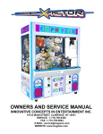
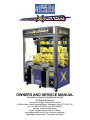
OWNERS AND SERVICE MANUAL
Cromptons Leisure International Limited
All Rights Reserved
Cromptons Leisure International Limited
4 Wilton Road, Haine Industrial Estate, Ramsgate, Kent CT12 5HG. UK
tel: +44 1843 593335 fax: +44 1843 588043
website: www.cromptons.com
e-mail: [email protected] (For Sales)
[email protected] (For all service enquiries)
[email protected]
1 ( For spares enquiries)
TABLE OF CONTENTS
INTRODUCTION…………………………….………....PAGE 3 & 4
GAME FEATURES
INSTALLATION………………………….……………...PAGE 5
TESTING / MAINTENANCE…………………………..PAGE 6
PROGRAMMING OPTIONS…………………………..PAGE 7 - 13
INTRODUCTION
USING THE PROGRAMMING OPTIONS
QUICK TROUBLESHOOTING………………………..PAGE 14 & 15
GAME REPAIR………………………………………....PAGE 16 - 19
OPERATIONAL BACKGROUND
TROUBLESHOOTING PHILOSOPHY
MECHANICAL REPAIR
PARTS LISTINGS……………………………………....PAGE 16
WIRING DIAGRAM...……………………………...…...PAGE 17
No part of this publication may be reproduced in any form without the written permission of Cromptons Leisure International Ltd.
Every effort has been made to ensure that the information contained in this manual is accurate.
Cromptons Leisure International Ltd. reserve the right to make alterations without prior notice.
5-27-03
2
INTRODUCTION
ELECTRONICS HOUSING - The unique housing for
the main electronics makes it extremely fast to
change the Main P.C. Board. Just pull on the spring
loaded retaining pin and pull the Electronics housing
from the game. To put new electronics in the game,
just push the housing in until you rear the retaining
pin snap into place. Removal or installation takes
just seconds!
OVERVIEW
Thank you for your purchase of the new
X-FACTOR™ crane from Cromptons. You will be
very satisfied with your new crane because of all the
great features we have packed into it.
We have spent a great deal of time designing new
features into the unit that not only increase revenues
but make servicing far easier than on previous
cranes.
INSTANT REPLAY AND FREE GAME FEATURES These unique features add to the play value of the
machine. The instant replay will allow the player to
re-deploy the claw in the exact same position as the
last drop provided there is a credit available in the
machine. A great feature for the "just missed it" attempt. The "Free Game" option adds a random opportunity for the player affording additional excitement.
GREAT FEATURES
REVOLUTIONARY CLAW DESIGN - We have designed the claw assembly for incredibly linear operation. The grab strength at full claw tip extension is
very similar to that when fully retracted. We use a
triple solenoid system with great reliability and durability. This system will also allow the claw to function
in the unlikely event that one of the solenoids were
to fail. This is possible because all 3 solenoids are
connected together rather than working independently. This method also allows the claw to work
much more consistently. The solenoids also have a
unique design that improves linear functionality. The
built in heat sinks keep the temperature of the solenoids more consistent which in turn also results in a
more consistent grab. The claws are ideally shaped
for the best balance of grab and slip. The shape has
been fine tuned for auto-percentaging of the machine & requires no adjustment.
CABINET CONSTRUCTION - The materials and
construction methods used in the manufacture of
this cabinet make it the strongest and most durable
in the industry. Thick powder coated steel outer
cabinet construction and internal bracing make the
cabinet extremely stiff and able to withstand repeated moves from location to location.
DISPLAY CABINET - the unique display cabinet allows for additional product display without encroaching into the play area. This design also allows us to
keep the cabinet width narrower. This is advantageous since the display cabinet can be slid into the
main cabinet if necessary to go through narrow
doorways - something the competition does not offer. The shelving units are fully adjustable and there
are attractive stainless steel retaining rods to hold
the prizes in place. The display cabinet is fully mirrored rear and sides to add a touch of class.
DOOR DESIGN - The front door of the game opens
easily and simply by turning the lock handle just 90
degrees. The control panels are mounted to the door
via "intelligent" wiring, keeping them out of the way
during service. The door is counterbalanced by nitrogen shock absorbers to raise the door fully out of the
way. This works much better that doors that open
outward in locations where space is an issue. Further we lift the door rather than use sliding doors because an unimpeded view of the playfield is much
more desirable, and sliding doors offer much less
security than the lift up design incorporated.
GRAPHICS PACKAGE - The cabinet colors and
graphics have been carefully chosen to create an
eye catching, yet classy expensive looking design.
3
INTRODUCTION
REMOTE PROGRAMMING UNIT - This crane uses
a remote programming unit that enables the customer to comfortably program the unit without having
to bend into awkward positions or read cryptic displays. The small hand-held unit uses a remote connecting cable and utilizes plain text graphics that are
easy and straight forward to read and understand.
Navigating through the menus is simple and quick.
All of the programming options are updated in real
time so you can test your changes as you play the
machine. There is no need to go in and out of programming mode to see if your changes worked correctly. This is a great time saving feature that makes
it easy for the machine servicer to do a better and
more accurate set up job.
FULLY INDEPENDENT OPERATION - The crane
has been designed so that both sides operate totally
independently. All electronics, power supplies and
mechanicals are separated into 2 distinct sides. This
means one side of the crane could fail, yet the other
side will continue to operate.
EASY SET-UP - When programming, the game has
been designed to work as efficiently and as broadly
as possible to minimize adjustments in the field. In
fact, under most circumstances the game will dispense small and large prizes with equal accuracy
using the same settings at the same time. For the
first time you can confidently load anything you want
mixed together at the same time onto the playfield.
NOTE: We strongly recommend using the autopercentaging feature whenever possible. This will
yield the most accurate payout percentages and the
most consistent payouts which will keep your customers happy and generate additional repeat play.
(It is not advisable to mix different sized prizes together when operating in manual mode).
LIGHTING - The playfield and top sign lighting is
achieved through the use of high output, long life florescent lamps. The lamps used have very long life
(Typical in excess of 20,000 hours) and are very reliable, quick and easy to replace.
INDEPENDENT DOOR ACCESS - The crane allows
the Front playfield door, the electronics access /
storage door, and the coin doors to all be accessed
separately. This means you can have different people service different areas of the game without having access to any other area prohibited.
4
INSTALLATION
SAFETY PRECAUTIONS
6. Insert the shelves into the desired slots in the
sides of the display unit.
IMPORTANT: FAILURE TO FOLLOW THESE DIRECTIONS CLOSELY COULD CAUSE SERIOUS
DAMAGE TO YOUR CRANE.
7. Reinstall the mirror strips onto the machine.
8. Install the stainless steel prize retention rods
above the shelving. NOTE: The rods should
be installed 2 holes up from the shelf itself.
WARNING: WHEN INSTALLING THIS CRANE, A
13 AMP GROUNDED SOCKET MUST BE USED.
FAILURE TO DO SO COULD RESULT IN SERIOUS INJURY TO YOURSELF OR OTHERS. FAILURE TO USE A GROUNDED SOCKET COULD
ALSO CAUSE IMPROPER CRANE OPERATION,
OR DAMAGE TO THE ELECTRONICS.
9. Plug the game in.
The machine is now ready for start up
START UP
USING AN IMPROPERLY GROUNDED GAME
COULD VOID YOUR WARRANTY.
Turn the power on to the machine and note the operation.
CRANE SET-UP
When powered up, the claws should drop into the
prize chute and retract.
BEFORE PLUGGING THE GAME IN, OR TURNING
IT ON, BE SURE THE GAME HAS BEEN SET TO
THE PROPER VOLTAGE. YOUR CRANE
SHOULD COME PRE-SET FROM THE FACTORY
AT THE CORRECT VOLTAGE, HOWEVER IT IS A
GOOD IDEA TO CHECK THE A.C. SUPPLY VOLTAGE BEFORE PLUGGING THE GAME IN.
You should notice the claws snapping shut during
the initial power up.
You should be able to hear game sounds at this
time.
PROGRAMMING
ASSEMBLY INSTRUCTIONS
Please see the following section of the manual for
detailed instructions on how to program your crane.
1. Carefully remove the crane from its packaging.
2. Using the supplied keys, unlock the front
door of the cabinet.
3. Cut all tie wraps holding the wagon assembly
and crane in place.
4. Unwrap the glass shelving for the display
unit.
5. Install the shelving by removing the (2) plastic mirror strips on either side of display unit.
The mirror strips are held in place with Velcro.
5
TESTING / MAINTENANCE
TESTING
CLEANING
After the initial setup, it is time to test your game for
proper operation.
Regular cleaning of this game will keep it looking
new, and greatly enhance its appeal.
1. Locate the game in its permanent location.
Clean the windows of your X-FACTOR™ with a
standard window cleaner.
2. Be sure the game has been properly plugged
in.
Clean the cabinet sides with a good cleaner and a
soft rag. A mild soapy solution can be used. You
may use a furniture polish when finished to protect
the game and make it look more attractive,
3. Verify that the game is set up for the proper
voltage, and turn the power to the game on.
4. The game will run through a test mode at
every startup. See test mode explanation in
the programming section for details.
NOTE: DO NOT USE ALCOHOL, THINNERS OF
ANY KIND, OR PINBALL PLAY FIELD CLEANERS
ON ANY OF THE CABINET SURFACES
ESPECIALLY THE DECALS.
5. Insert coins into the machine at least ten
times into the coin mech to assure proper operation.
6. Check the credit and prize counters for
proper operation.
7. Check game volume during busy time at location to set it at the proper level.
6
PROGRAMMING
THE MULTI-PROGRAMMER HAS THE FOLLOWING PUSHBUTTONS:
6
1
5
2
4
3
1
Select upward and downward arrow. They are used to move up and down through the
various menus and settings.
2
Pushbutton is used to close a menu, or to perform certain actions, e.g. setting meters to
zero.
3
With this pushbutton, you can obtain more information about each setting.
4
In some menus, it is possible to directly test the various set values by pressing this button, e.g. we select pick up power; press test and the grabber closes using the power that
you have set.
5
Pushbutton is used to open a menu.
6
With these buttons you can change the settings.
7
PROGRAMMING
VERSION INFO MENU
PROGRAMMING THE GAME
Turn on the power to the game.
Machine Type - “X-Factor”
Machine SW Revision - XX.XX (major/minor ver-
Open the front door and locate the main board housings in the center of the game. Insert one end of the
cable provided in the jack on the main board housing and the other to the hand held “MultiProgrammer”.
sion codes)
Machine SW Date - In YYYY-MM-DD format
Multi-Programmer Version - XX.XX
Multi-Programmer SW Date - In YYYY-MM-DD
format
The display on the “Multi-Programmer” should appear as shown in the photo below. Note that the
lower case “c” is displayed. This indicates that the
“Multi-Programmer” is connected & functioning normally.
STATUS SNAPSHOT MENU
Regulator target payout % - Target payout %
Cash box payout % - Current % of money out per
money in
Total payout % - Total % of money out per
money in
Grab power now - Live data
ACCOUNTING MENU
Daily meters - To Daily Meters menu
Total meters - To Total Meters menu
DAILY METERS MENU
Number of plays - The current count of games
played
MAIN MENU
Prizes won count (wins) - The current count of
the prizes won
Backlight - Turn on or off
Prizes won value - The current value of the prizes
Version Info - To Version Info menu
Cash box money value in - The current value of
won
the money in the cash box
Current payout % - 100 * (current prizes won
value) / (current money in value)
Clear daily meters COMMAND to reset these soft
counters, when emptying cashbox
Status Snapshot - To Status Snapshot menu
Accounting - To Accounting menu
Setup - To Setup menu
Test Play - To Test Play menu
TOTAL METERS
Diagnostics - To Diagnostics menu
Number of plays - The total count
Prizes won count (wins) - The total count
Prizes won value - The total value
Total money value in - The total value
Total payout % - The total payout
Clear total meters - COMMAND to reset these
Data Transfers - To Data Transfers menu
Reset MP Device - COMMAND to Reset the programmer
soft counters, after major setup
8
PROGRAMMING
CHANGE BASE COIN
SETUP MENU
TO BASE COIN VALUE MENU
Attract Settings - To Attract Settings menu
Credit Settings - To Credit Settings menu
Payout Settings - To Payout Settings menu
Game Settings - To Game Settings menu
Motor Settings - To Motor Settings menu
Grab Settings - To Grab Settings menu
Reload Factory Defaults - COMMAND to reset
VALUE OF CHANNEL 1 COIN PULSE
This setting determines the money value per channel. (per coin) The range for this option is 1 - 60. The
default setting is “2”.
all Settings values to their defaults
VALUE OF CHANNEL 2 COIN PULSE
This setting determines the money value per channel. (per coin) The range for this option is 0 - 60. The
default setting is “0”.
ATTRACT SETTINGS MENU
ATTRACT TIMER
This setting determines the duration of time between
attract modes in minutes. The range for this option is
1 - 45. The default setting is 3.
VALUE OF CHANNEL 3 COIN PULSE
This setting determines the money value per channel. (per coin) The range for this option is 0 - 60. The
default setting is “0”.
ATTRACT SOUND VOLUME
This setting determines the sound volume of the
game. Setting a “0” turns the sound to minimum.
Setting a “1” turns the sound to maximum. The default setting is 1.
VALUE OF CHANNEL 4 COIN PULSE
This setting determines the money value per channel. (per coin) The range for this option is 0 - 60. The
default setting is “0”.
ATTRACT TYPE
VALUE OF CHANNEL 5 COIN PULSE
This setting determines what type of attract mode (if
any) is used. Setting a “0” turns the attract mode off.
Setting a “1” makes sound only. Setting a “2” allows
movement only. Setting a “3” allows both sound &
movement. The default setting is 3.
This setting determines the money value per channel. (per coin) The range for this option is 0 - 60. The
default setting is “0”.
VALUE OF CHANNEL 6 COIN PULSE
CREDIT SETTINGS MENU
This setting determines the money value per channel. (per coin) The range for this option is 0 - 60. The
default setting is “0”.
COST PER GAME (CREDIT)
This setting is used to determine the value of 1
credit. (Coin)
LAST MONEY PUT IN
DIAGNOSTIC
BASE COIN VALUE
This setting determines the amount by which other
money settings are incremented. The range for this
option is 1 - 20. The default setting is “1”.
CREDITS LIMIT
This setting determines the number of credits allowed. The range for this option is 0 - 99. The de-
9
PROGRAMMING
fault setting is “0”. When the limit has been set, no
more coins will be accepted for credit.
RESTART REGULATOR
This COMMAND is used to restart the payout regulator. This is designed for a new prize or in the event
of large fluctuations in the vending price or purchase
price. Always restart the game after adjusting the
machine.
FREE GAME 1-in-X
This setting determines the amount of time, in seconds, at which a free game may be won. The range
for this setting is 1 - 20. The default setting is “4”.
GAME SETTINGS MENU
BASE COIN VALUE MENU
GAME TIMER
BASE COIN
This setting is used to set the duration of the game
in seconds. The range for this setting is 15 - 60. The
default setting is “20”.
This setting is used to set the amount by which other
money settings are incremented. The range for this
setting is 1 - 20. The default setting is “1”.
MOTOR SETTINGS MENU
PAYOUT SETTINGS MENU
(Regulator)
FORWARD / BACK MOTOR SPEED
This setting allows for the adjustment of the forward / backward speed of the crane. The range for
this setting is 10 - 20 with 10 being slow and 20 being fast. The default setting is “20”.
MONEY VALUE OF EACH PRIZE
This setting is used to set the value of each prize determined by the value of the BASE COIN VALUE.
The range for this setting is 1 - 200. The default setting is “20”.
SIDEWARD MOTOR SPEED
This setting allows for the adjustment of the left /
right speed of the wagon. The range for this setting
is 10 - 20 with 10 being slow and 20 being fast. The
default setting is “20”.
REGULATOR TARGET PAYOUT
This setting determines the value set by the operator
for payout percentage. The range for this setting is
20 - 50%. The default setting is 33%.
DOWN MOTOR SPEED
This setting allows for the adjustment of the down
speed of the claw. The range for this setting is 10 20 with 10 being slow and 20 being fast. The default
setting is “20”.
TOTAL PAYOUT PERCENTAGE
(INFORMATION)
DAILY PAYOUT PERCENTAGE
(INFORMATION)
UP MOTOR SPEED
FAIL LIMIT PERCENTAGE
This setting allows for the adjustment of the up
speed of the claw. The range for this setting is 10 20 with 10 being slow and 20 being fast. The default
setting is “20”.
This setting is used to set the limit for out of range
payouts. If the payout percentage is over the set
limit, the game will no longer accept coins. The
range for this setting is 0 - 50%. The default setting
is 0%.
10
PROGRAMMING
GRAB SETTINGS MENU (Claw)
RANDOM BOOST TIME
INDICATE POWER
This setting determines the time for a random pickup
boost. A setting of “0” will disable this feature while a
setting of “1” will enable it. The default setting is “1”.
This display shows the real time “Grab” power when
the game is being played or not.
STOP AND DROP
PICKUP POWER
This setting is used for allowing the claw to descend
to a predetermined distance before releasing a
prize. This setting is extremely useful for fragile
prizes. Settings for this feature are: “0” = No and a
“1” = Yes. The default setting is “0”
This setting determines the initial pickup strength of
the claw. The range for this setting is 45 - 99. The
default setting is ”70”.
RETAIN POWER
TEST GRAB SEQUENCE
This setting determines the pickup power to go to,
after the pickup timer has elapsed. The range for
this setting is 20 - 99. The default setting is “50”.
Use this COMMAND to test the entire grab / drop /
lift cycle using the game’s current settings.
DIG TIME
TEST PLAY MENU
This setting determines the amount of time for the
claw to dig in when down. The range for this setting
is 0 - 24 seconds in 1/8 second increments. The default setting is “4”.
TEST FREE GAME
COMMAND - one free game with no meters.
BONUS UNTIL WIN
PICKUP TIME
COMMAND - no free game to be played, but will allow for full grab power until next win.
This setting is used to determine the amount of time
the claw will be at pickup power after dig. The range
for this setting is 0 - 24 seconds in 1/8 second increments. The default setting is “8”.
FREE PLAY MODE
COMMAND - play free games with no meters.
HOLD AT TOP TIME
This setting is used to determine the amount of time
the claw will be held at the top. The range for this
setting is 0 - 80 seconds in 1/8 seconds increments.
The default setting is “0”.
NORMAL PLAY MODE
COMMAND - no free games, restore game to normal play.
PICKUP RETAIN TIME
DIAGNOSTICS MENU
This setting is used to determine the step length of
smooth transition from Pickup to Retain power. The
range for this setting is 1 - 99 seconds in increments
of .005 seconds. The default setting is 2.
TESTS
TO TESTS MENU
ERRORS
TO ERRORS MENU
11
PROGRAMMING
GET DEFAULT SETTINGS
TESTS MENU
Resets the programmer’s current settings to default
values, even if it is not connected to the crane.
When connected to the crane, it also sends a
“restore defaults” command to the crane and then
queries its resulting settings, and uses those as its
current settings. This means that if the crane uses
different defaults than the programmer, the crane’s
values “win”.
LAST MONEY PUT IN
Allows monitoring of the last money put in and test
the coin in lines.
TEST VERTICAL GRAB MOTOR
MOTOR SENSORS
CLEAR DAILY METERS
This test will indicate which stop sensors are on.
Zeroes the displayed daily meters on the programmer. When connected to the crane it also sends it a
zero command for these account values.
TEST FORWARD MOTOR
TEST SIDEWARD MOTOR
CLEAR TOTAL METERS
OTHER SENSORS
Shows a field of letters corresponding to active sensors.
- NOT IMPLEMENTED -
Zeroes the displayed total meters on the programmer. When connected to the crane it also sends it a
zero command for these account values.
TEST GRABBER
PUT GAME SETTINGS
When connected to the crane, this command takes
the programmer’s current settings (but not account
info) and puts them into the crane. It then reads
back the same values from the crane, and if the
crane replies with any different values, those values
become part of the programmer’s current settings.
TEST LAMPS
ERRORS MENU
NUMBER OF METER ERRORS
SELECT SETTINGS BANK
NUMBER OF MOTION ERRORS
The programmer has 4 banks where it can save
copies of setting information. This lets you select
which is the active setting save bank.
NUMBER OF GRABBER ERRORS
CLEAR ERROR COUNTS
SAVE SETTINGS TO SETTINGS BANK
COMMAND - Clears the diagnostic error counts.
Takes the programmer’s current settings and saves
it into the active setting save bank. This overwrites
any previous save data in that bank.
DATA TRANSFERS MENU
GET GAME DATA
LOAD SETTINGS FROM SETTINGS
BANK
Loads the crane’s current settings AND account info
into the programmer. Once this is done, the programmer’s current settings are in sync with the
crane until manually changed.
Takes the settings from the active settings save
12
PROGRAMMING
bank and copies it into the programmer’s current
settings. If a bank has never been saved to, it holds
the default values. The new current values are not
sent to the crane, however; you must do this explicitly as a separate step via the “Put game settings”
command.
SELECT METERS BANK
The programmer has 8 banks where it can save
copies of account information. They are totally separate from the settings save banks. This lets you select which is the active account save bank.
SAVE METERS TO METERS BANK
Takes the programmer’s current accounts and saves
it into the active account save bank. This overwrites
any previous save data in that bank. You would do
this after loading the crane’s account data via the
“Get game data” command.
LOAD METERS FROM METERS BANK
Takes the accounts from the active account save
bank and copies it into the programmer’s current
settings. If a bank has never been saved to, it holds
zeroes. If connected to a crane, the crane’s account
data may overwrite the programmer’s current account info at a later time. This command exists to
help you record account data from multiple cranes
and then review it later, away from the cranes. What
you should do is this (1) connect to a crane; (2) get
its game data; (3) save its accounts to a bank; (4)
repeat steps 1-3 for other cranes, using other save
banks; (5) away from the cranes, load the meters on
at a time to current to review and write down.
13
QUICK TROUBLESHOOTING
PROBLEM
NO GAME POWER
PROBABLE CAUSE
ON-OFF SWITCH ON THE GAME IS TURNED OFF
BLOWN A.C. POWER FUSE
GAME NOT PLUGGED OR CORD DAMAGED
BAD TRANSFORMER
TRANSFORMER HARNESS NOT CONNECTED
BAD POWER MODULE
SOLUTION
TURN POWER ON
REPLACE WITH PROPER FUSE
CHECK POWER CORD
CHECK FOR PROPER VOLTAGES
CHECK HARNESS
REPLACE POWER MODULE
GAME WILL NOT TAKE MONEY BAD COIN SWITCH
OR GIVE CREDITS CORRECTLY COIN DISCOUNTING SET WRONG
COINS PER CREDIT SETTING INCORRECT
BAD COIN MECHANISM
LOOSE OR DAMAGED HARNESSING
BAD MAIN P.C. BOARD
CHECK W/METER AND REPLACE
CHECK PROGRAMMABLE SETTING
CHECK PROGRAMMABLE SETTING
ADJUST OR REPLACE
CHECK W/METER—REPAIR
REPAIR OR REPLACE MAIN BOARD
DISPLAYS DO NOT WORK
BLOWN FUSE
BAD DISPLAY P.C. BOARD
BAD MAIN P.C. BOARD
LOOSE OR DAMAGED DISPLAY HARNESSING
REPLACE WITH PROPER FUSE
REPAIR OR REPLACE P.C. BOARD
REPAIR OR REPLACE P.C. BOARD
CHECK W / METER AND REPAIR
CRANE OR WAGON DOES NOT
MOVE
BAD MOTOR
LOOSE OR DAMAGED HARNESSING
BAD SWITCH ON BUTTON OR JOYSTICK
BAD HARNESSING TO BUTTONS OR JOYSTICK
BLOWN FUSE TO MOTORS ON MAIN P.C.B.
REPLACE MOTOR
CHECK W / METER—REPAIR
REPLACE SWITCH
CHECK W / METER—REPAIR
REPLACE WITH PROPER FUSE
CRANE KEEPS TRYING TO
MOVE IN TO THE HOME
POSITION
BAD LIMIT SWITCH (S)
LIMIT SWITCH NOT ALIGNED WITH ACTUATOR
REPLACE SWITCH (S)
ALIGN SWITCH AND ACTUATOR
CLAW WILL NOT CLOSE
BLOWN FUSE TO CLAW ON MAIN P.C. BOARD
BAD COIL
LOOSE OR DAMAGED HARNESSING
CLAW HAS MECHANICALLY JAMMED
REPLACE WITH PROPER FUSE
REPLACE COIL
CHECK W / METER AND REPAIR
FIND JAM AND REPAIR
CLAW STAYS CLOSED
BAD DRIVE TRANSISTOR ON MAIN P.C.B.
CLAW HAS MECHANICALLY LOCKED
REPLACE TRANSISTOR
FIND JAM AND REPAIR
SKILL LEVELING IS NOT
FUNCTIONING
PROGRAMMING IS NOT CORRECTLY SET
BAD PRIZE SENSOR
LOOSE OR DAMAGED SENSOR HARNESS
SET OPTIONS “9”, “16” AND “17”
REPLACE PRIZE SENSOR
CHECK W / METER AND REPAIR
CLAW GOES DOWN AND THEN
UP BUT DOES NOT CLOSE
DOWN SWITCH BAD
LOOSE OR DAMAGED HARNESS TO DOWN
SWITCH
REPLACE DOWN SWITCH
CHECK W / METER AND REPLACE
CLAW COMES UP AND ABOUT
10 SEC. PASSES BEFORE
CRANE MOVES TO THE HOME
POSITION
UP SWITCH BAD
LOOSE OR DAMAGED HARNESS TO UP SWITCH
BROKEN “UP” SPRINGS
REPLACE UP SWITCH
CHECK W / METER AND REPLACE
REPLACE SPRINGS
CRANE OR WAGON WHEELS
SLIP
MISSING OR DAMAGED O-RING DRIVE BELTS
LOOSE SET SCREWS IN WHEELS
LOOSE SET SCREWS IN DRIVE COUPLER
RAILS NEED TO BE SCUFFED
REPLACE O-RING BELTS
TIGHTEN SET SCREWS
TIGHTEN SET SCREWS
SCUFF TOP OF RAILS WITH
SANDPAPER
14
QUICK TROUBLESHOOTING
- NOTE: If the Wagon does not move smoothly through a full travel from left to right, check to see that the
wheel spacing is correct. If the spacing is correct, then check the 2 cabinet rails for burrs that may cause the
wheels to bind.
- NOTE: If the Crane does not move smoothly through a full travel from front to back, check to see that the
wheel spacing is correct. If the spacing is correct, then check the 2 separator rails for burrs that may cause
the wheels to bind.
- NOTE: If the Micro track for the left / right movement is binding during its travel, check to see if the top mirror
bracket’s edge, also the shelf the micro track rides on, has been de-burred.
- NOTE: If the front door is having trouble closing fully, check to see that all harnessing is out of the way for
the door to close. Next, check to see that the door is aligned properly.
- NOTE: If the door will not lock properly or locks with difficulty, check to see that the lock rotates smoothly.
Next, check that the lock rods are not binding on the lock cam or the lock rod guides. Next, check that all friction points have been lubricated with molly grease. Finally, if need be, adjust the lock rod guides such that the
door closes and locks smoothly.
- NOTE: If at the beginning of the self test mode, the claw does not drop, one or more of the following may
apply. The prize sensor is not working or is blocked. The string or string lever is mechanically binding. The up
or down switch is sticking or misaligned from its actuator.
- NOTE: If claw stays closed, it is likely that the diode has blown and the transistor controlling the claw has
also blown. Shut off the game immediately and have a qualified technician install a new coil assembly and
transistor on main board.
- NOTE: If claw is jerky while being lowered, it is likely that the up spring is missing or has not been slightly
elongated properly. Another possibility is that the string has mechanically bound on the spool. To fix the string
binding, you will need to use the “Multi-Programmer”. Plug the programmer into the game Enter the Main
Menu, Diagnostics Menu & then the Tests Menu. Using the Tests Menu, lower the claw all the way until it
starts to wind up backwards. Reverse the motor direction to raise the claw mechanism and properly rewind
the string on the spool. Exit the programming mode and the string should be free of mechanical binding.
- NOTE: If the claw stays open, first check for bad fuses on the main board. Next check that there are no
wires dislodged from the connectors in the harness between the wagon and crane, the harness between the
wagon and the main board, the crane assembly and the wagon assembly. If the problem still exists, and no
fuses are blown or wires dislodged, it is likely that the transistor controlling voltage to the claw has blown on
the main board. Have the coil assembly and transistor on the main board replaced by a qualified technician.
- NOTE: If the crane / wagon, in the home position, tries to move left or back, check to see that the actuators
are both present. Next, check to see that the sensors are present. Next, check to see that the sensors and
actuators are aligned. Then check to see that the sensor wires are not dislodged from the connectors. Finally,
replace the sensor, it is likely to be bad.
15
PARTS LISTINGS
MECHANICAL PARTS
5011
SPRING
BC1013
LOCK CAM
BC3028
SIDE GLASS
CG1054
WAGON ROLLER SHAFT
CG1055
WAGON MOTOR END PLATE
CG1055X
WAGON ASSEMBLY
CG1056
WAGON END PLATE
CG1057
WAGON SEPARATOR RAIL
CG1058
WAGON DRIVESHAFT
CG1059
WAGON DRIVESHAFT COUPLER
CG1060
TRACK GUIDE MOUNT
CG1061
CRANE MOTOR HOUSING
CG1061X
CRANE ASSEMBLY
CG1062
CRANE MOTOR HOUSING CAP
CG1063
CRANE STRING LEVER
CG1064
COIL STOP BLOCK COVER
CG1066
CRANE UP SPRING
CG1068
BUSHING
CG1069
TRACK MOUNT RAIL
CG1069X
TRACK MOUNT RAIL ASSEMBLY
CG1071
BRACKET
CG1077
STRING ROLLER
CG1078J
CLAW (SILVER PAINT)
CG1078JX
CLAW ASSEMBLY
CG2012
SENSOR (FWD)
CG2013
SENSOR (L & R)
CG3008A
MICRO TRACK 62 LINK
CG3008B
MICROTRACK END LINK SET
CG3019
CAGE RETAINER CAP
CG3019X
THUMB SCREW ASSEMBLY
CG3030
WHEEL (LARGE)
CG3032
STRING SPOOL SIDE
CG3034
COIL STOP BLOCK
CG3035
COIL CAP
CG4003
O RING
CG4004
STRING
CG5014
LOCK - T-HANDLE
CG5015
LOCK - BARREL
CX1051
SHOCK (HYDRAULIC)
CX1052
CASTER (SWIVEL)
CX1053
CASTER (SWIVEL - LOCKING)
CX1072-P100 SOLENOID MOUNTING PLATE
CX1073-P100 PLATE BOX BOTTOM
CX1075
CRANE CONNECTING PIN
CX1076-P800 HEAT SINK PLATE
CX3026
MIRROR (REAR WALL)
CX3027
GLASS (FRONT)
CX3036
FINGER PIN
CX3037
CLAW SPIDER
GRAPHICS & DECALS
BC7017
CX7005
CX7006
CX7008
CX7012
CX7026
CX7027A
CX7028
CX7029A
CX7052
CX7056
CX7057
CX7061
CX9001
DECAL (CHROME MYLAR STRIP)
DECAL (BUTTON INSTANT REPLAY)
DECAL (BUTTON ARROW)
DECAL (SIDE “X”)
DECAL (CONTROL PANEL OVERLAY)
DECAL (LEFT MARQUEE X FACTOR)
DECAL (REAR MARQUEE X FACTOR)
DECAL (RIGHT MARQUEE X FACTOR)
DECAL (FRONT MARQUEE X FACTOR)
DECAL (MIRROR GRID X FACTOR)
DECAL (PRIZE DOOR X FACTOR)
DECAL (CROMPTONS LOGO)
DECAL (CLAW CROMPTONS LOGO)
SERVICE MANUAL
ELECTRICAL / ELECTRONIC
PARTS
2133CW
8284
8312
8395
CG2002CEX
CG2008
CX2009
FP2007
HD20224
HD2364
SM2008
ROPE LIGHT
BALLAST WH6-120L
BULB PL-L 40W
BULB #192 WEDGE
TRANSFORMER
MOTOR
SOLENOID
SPEAKER (4” ROUND)
COUNTER 5V
FAN 120V
TRANSFORMER
RECOMMENDED SPARES
CG4003
CG4004
8312
8395
CG2008
CX2009
16
O RING
STRING
BULB PL-L 40W
BULB #192 WEDGE
MOTOR
SOLENOID
WIRING DIAGRAM
17