1
®
ELECTROMECHANICAL AND
ELECTRONIC ICE CUBER
SERVICE MANUAL
1525 East Lake Road, Erie, PA 16511-1088
814/453-6761
FAX 814/455-6336
©2004 KDIndustries, Inc., Erie, PA U.S.A.
Printed in U.S.A.
3/04
LIT-09503
A Tradition of Excellence In Ice Equipment.
Table of Contents
Page No.
Table of Contents
1B
Key to Electronic Model Numbers
2B
Key to Electro-Mechanical Model Numbers
3B
Installation Specifications- Electronic
4B
Operational Components- Electronic
6B
Sequence of Operation- Electronic
11B
Electrical Circuits
13B
Functional Tests
25B
Trouble, Cause and Remedy
26B
Service and Troubleshooting
33B
Installation and Adjustments
43B
Preventative Maintenance
47B
Operational Components- Electro-Mechanical
49B
Installation Specifications- Electro-Mechanical
53B
Kold-Draft® Service & Parts Manual
-1B-
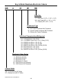
Key to Model Numbers-Electronic Cubers
GB
4
01
W
HK
Cube Size
C = Full Cube (1-1/4” x 1-1/4” x 1-1/4”)
HK = Half Cube (5/8” x 1-1/4” x 1-1/4”)
K = Cubelet (5/8” x 5/8” x 1-1/4”)
Condenser Type
A = Air Cooled Condenser-Self Contained
W = Liquid Cooled Condenser-Self Contained
R = Remote Air Cooled Condenser
Electrical Characteristics/Refrigerant
01 = 115 Volt-60 Hz.-1 Ph. (R-12)
02 = 115-208/230 Volt-60 Hz.-1 Ph. (3-Wire) (R-12)
03 = 208/230 Volt-60 Hz.-1 Ph. (R-12)
04 = 208/230 Volt-60 Hz.-1 Ph. (R-502)
05 = 208/230 Volt-60 Hz.-3 Ph. (3-Wire) (R-502)
06 = 200 Volt-60 Hz.-1 Ph. (R-12)
07 = 230 Volt-50 Hz.-1 Ph. (R-12)
08 = 380/230 Volt-50 Hz.-3 Ph. (5-Wire) (R-502)
Electronic Cuber Series
3 = 300 Series (3/4 HP)
4 = 400 Series (3/4 HP)
5 = 500 Series (1 HP)
6 = 600 Series (1-1/2 HP)
10 = 1000 Series (2 HP Nominal)
12 = 1200 Series (2 HP Nominal)
Cabinet Width
GB = Horizontal Unit (42” Wide)
GT = Slimline Unit (28-1/2” Wide)
Kold-Draft Service & Parts Manual
2-B
Key to Model Numbers-Electro-Mechanical Cubers
GB
1
A
N
4
HK
E
Electronic
Cube Size
C = Full Cube (1-1/4” x 1-1/4” x 1-1/4”)
HK = Half Cube (5/8” x 1-1/4” x 1-1/4”)
KK = Half Cube (5/8” x 1-1/4” x 1-1/4”)
K = Cubelet (5/8” x 5/8” x 1-1/4”)
Ice Production Per 24 Hours (Nominal)
64 = 75 lbs. w/40 lb. Storage Bin Included
1 = 110 lbs. w/65 lb. Storage Bin Included
2 = 200 lbs.
6 = 600 lbs.
10 = 1000 lbs.
3 = 300 lbs.
7 = 700 lbs.
11 = 1000 lbs.
4 = 400 lbs.
8 = 800 lbs.
12 = 1200 lbs.
5 = 500 lbs.
9 = 900 lbs.
16 = 1600 lbs.
20 = 2000 lbs.
Code Letter
NSF = National Sanitation Foundation Listed
D = 115/230 Volt-60 Hz.,-3-wire, NSF Listed
5 = 500 Series (1 HP)
Condenser Type
A = Air Cooled Condenser-Self Contained
W = Liquid Cooled Condenser-Self Contained
R = Remote Air Cooled Condenser-Precharged
X = Remote Air Cooled Condenser
Compressor Horsepower Rating
0 = No Condensing Unit
1 = 1 HP
2 = 11,000 BTU
3 = 1/3 HP
4 = 14,000 BTU
5 = 1/2 HP
Machine Type
GB = Horizontal Unit, Mounts on a Bin (42” Wide)
GT = Slimline Unit, Mounts on a Bin (28-1/2” Wide)
GY = Self Contained Compact Unit (30” Wide)
GS = Self Contained Compact Unit (24” Wide)
IS = Self Contained Dispenser (31-1/4” Wide)
Kold-Draft Service & Parts Manual
3-B
6 = 1/5 HP
7 = 3/4 HP
8 = 3/4 HP
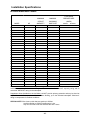
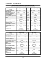
Installation Specifications
60 Hertz Electronic Cubers
FUSE/HACR
MINIMUM
MINIMUM
CIRCUIT
INCOMING
BREAKER SIZE
(AMPS)
MODEL
HP
AMPACITY
WIRE SIZE
NORMAL
GT301A
3/4
22.7
10
25
35
GT301W
3/4
17
12
20
25
GT401A/GB401A
3/4
25
10
25
40/35
GT401W/GB401W
3/4
18
12
20
25
GT401R/GB401R
3/4
20.9
10
25
35
GT402A/GB402A
3/4
16
12
20
20
GT402W/GB402W
3/4
15
14
15
20
GT402R/GB402R
3/4
16.9
12
20
25
GB503A
1
14.4
14
15
20
GT503W/GB503W
1
13.3
14
15
20
GT503R/GB503R
1
12.2
14
15
20
GB603A
11,000 BTU
20
12
20
30
GT603W/GB603W
11,000 BTU
15
14
15
20
GT603R/GB603W
11,000 BTU
18.9
12
20
30
GB903/1003W
14,000 BTU
17
12
20
25
GB903/1003R
14,000 BTU
19.3
12
20
30
GB1204W
27,600 BTU
28.2
10
30
45
MAXIMUM
GB1204R
27,600 BTU
28.2
10
30
45
GB1205W
22,500 BTU
17.8
12
20
30
GB1205R
22,500 BTU
17.9
12
20
30
IS401A
3/4
30
10
30
40
IS401W
3/4
23
10
25
30
IS503W
1
15
14
15
20
GY3A
1/3
15
14
15
15
GY3W
1/3
15
14
15
15
GT7A
3/4
22.7
10
25
35
GT7W
3/4
17
12
20
25
NOTE: Maximum Branch Circuit Fuse or HACR type Circuit Breaker size is dependent on the size of the
conductors supplying the Ice Maker. They must be no less than the minimum ampacity rating and no
more than "Maximum" rating on the nameplate.
Supplement fuses (installed on the Ice Maker) do NOT provide primary protection and may be sized as
required for continuous operation without nuisance blowing, up to the indicated nameplate "Maximum"
rating to compensate for ambient conditions.
SPECIAL NOTE: Wire sizes on this chart are good up to 80 feet.
Anything 80 feet to 150 feet increase wire 1 size.
Any runs 150 feet to 250 feet increase the wire 2 sizes.
Kold-Draft® Service & Parts Manual
-4B-
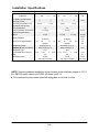
Installation Specifications
Specifications
Water Levels, Pressures, Cycles and Charges
(higher than average temperatures increase pressures and cycle times)
GB1200
GB903/GB1000
GB600/GT600
Model
Cube Size
Full Water Level Distance
below top of tank
C
HK
K
2-5/8" 2-3/4" 3-1/2"
C
HK
K
2-5/8" 2-3/4" 3-1/2"
C
HK
2-5/8" 2-3/4" 3-1/2"
Suction Pressure after Defrost
55-60 psig
20 psig
20 psig
Suction Pressure before
Defrost
10-15 psig
0-2 psig
0-2 psig
Defrost Pressure
70 psig max. 100-110 55 psig max.
with CPR valve
psig with CPR valve
Cycle Times (approximate)
19 min. 17 min. 11 min. 27 min. 22 min. 15 min.
40-60
psig
40-60 psig
21 min. 17 min. 12 min.
Refrigerant Charge
Remotes (R) see note below
3 lbs.
3 lbs.
3 lbs.
Refrigerant Type
R-502
R-12
R-12
Approximate lbs. of ice per
batch
Compressor Size
Model
Cube Size
Full Water Level Distance
below top of tank
15 lbs. 14 lbs.
15 lbs. 14 lbs.
7-1/2
lbs.
7 lbs.
4 lbs.
14,000 BTU
TXV controlled
11,000 BTU
TXV controlled
GB500/GT500/IS500
GB400/GT400/IS400
GT300
C
HK
K
2-5/8" 2-3/4" 3-1/2"
Suction Pressure before
Defrost
Defrost Pressure
C
HK
K
2"
11-13 psig
0
3 psig
0
40-60 psig
40-60 psig
40 psig
3 lbs.
Refrigerant Type
R-12
R-12
7 lbs.
4 lbs.
9,800 BTU
TXV controlled
7-1/2
lbs.
7 lbs.
K
3"
20-25 psig
3 lbs.
Compressor Size
HK
15-20 psig
26 min. 20 min. 13 min. 28 min. 25 min. 14 min.
7-1/2
lbs.
C
2-5/8" 2-3/4" 3-1/2"
Refrigerant Charge
Remotes (R) see note below
Approximate lbs. of ice per
batch
8 lbs.
GB1205: 22,500 BTU
TXV controlled
GB1204: 27,600 BTU
TXV controlled
Suction Pressure after Defrost
Cycle Times (approximate)
8 lbs.
K
28 min. 21 min. 15 min.
13 oz. GT301A
10 oz. GT301W
R-12
4 lbs.
6,800 BTU
TXV controlled
3-3/4
lbs.
3-1/2 lbs. 2 lbs.
6,800 BTU
cap. tube controlled
NOTE: Remote condenser application cubers require a total minimum charge of 10-1/2
lbs. GB1200 series cubers use R-502, all others use R-12.
{ For maximum fuse size check electrical rating plate on left rear of cuber.
Kold-Draft® Service & Parts Manual
-5B-
Operational Components
Kold-Draft® Electronic Cuber Construction
Skins
The skins consist of the top, left end, back, right end panels and front inspection panel.
Condensing Units
Varies with each model. For compressor size and charge, refer to the Water Levels,
Pressures, Cycles and Charges Chart on the previous page.
Evaporator
The GB series Full Cube (C) evaporator is made up of 108 cells, 1-1/4" each way.The
Cubelet (K) evaporator is made up of 216 cells, 1-1/4" x 1-5/8" x 5/8" deep. The Half
Cube (HK) evaporator is made up of 216 cells, 5/8" x 1-1/4" x 1-1/4" deep. The material
is copper and the entire assembly is tinned, preventing corrosion and making its use
acceptable to any sanitary board. A seal is not required between the evaporator and
water plate, normally there is an approximately 1/32" clearance between them. Refer to
Water Plate-Evaporator Alignment for adjustments.
Note: GT300 evaporators contain 1/2 the number of cells of a GB evaporator.
Refrigerant Control
1. Thermostatic expansion valves are used on all GB and IS models and GT400,
GT500 and GT600 models. For replacement of the valve, consult the Parts
Price List for type of expansion valve. It has been regulated properly on test
before being shipped, to give minimum superheat and maximum flooding of the
evaporator and should not require adjustment.
Sometimes after shipping or storage, the expansion valve sticks and allows
more refrigerant to pass than necessary, increasing the low side pressure
and temperature, thus excessive frostback and a long cycle. If this condition
does not correct itself during the second cycle, it will be necessary to adjust the
superheat on the expansion valve, closing the valve clockwise 1/8 to 1/4 turn to
increase superheat, reducing the suction pressure and preventing frostback. If
valve hunts (varies suction pressure up and down) more than 2 to 3 lbs. when
suction pressure is below 13 lbs., it indicates that the valve should be opened
more.
2. The GT300 series are capillary systems and do not have an expansion valve.
Water Plate
The water plate is made of approved plastics and is used to distribute the water
through jet holes into the freezing cells of the evaporator, and also to return water
through two drain holes in each cell in the water plate. On the front of the water plate is
a control stream, that should be set at the base of the dam once the water fill is
complete. Backing the screw out increase the flow. At the end of a cycle when cubes
are virtually frozen there is an increasing water pressure in the system causing the
stream to rise and go over the dam dumping dreg water.
Circulation Tank
The circulation tank is secured to the bottom of the water plate. It serves as a reservoir
to hold enough water to make one batch of ice.
Kold-Draft® Service & Parts Manual
-6B-
Operational Components
Circulation Strainer
The circulation strainer has a large screen inserted in the tank outlet to prevent dirt or
particles of precipitated mineral from clogging the jet holes or the control stream. It also
protects the pump impeller. If the screen becomes clogged with precipitated minerals, it
is advisable to clean the whole circulation system with ice machine cleaner.
Water Pump
The water pump is a centrifugal type, direct with sealed bearings that require no
lubrication. The inlet tube is at the bottom of the water circulation tank, and the outlet at
the top of the pump is connected to the header of the water plate.
Water Level Probe Assembly (GBR-03170)
This probe is connected to the main water circulation tank by means of flexible tubing.
The height of water in the probe assembly indicates the height of water in the
circulation tank. Thermistor probes determine water valve on/off levels. Refer to the
Water Levels, Pressures, Cycles and Charges chart for the correct setting per model
for the upper probe. The bottom probe is positioned so that 15-30 seconds after the
water flows over the dam on the control stream box on the water plate, the water level
is below the glass tip and harvest is initiated.
Pump and Defrost Switch
A spring loaded switch is mounted in the control box. It controls the defrost circuit and
water pump, and is operated by an adjustable screw in the lift plate attached to the
water plate. As the water plate closes after defrost, the adjustable screw lifts up and
makes contact with the pump switch to cut one connection to the defrost circuit and
start the circulation water pump.
Water Inlet Valve
The water inlet valve is mounted int front left of the freezing compartment and controls
the rate of flow of water into the water tank when the cuber is filling. It is a constant flow
type requiring a minimum 15 psi. An external "Y" type strainer is used with the valve.
For pressures over 100 psi or if there is water hammering, a pressure regulator should
be used.
Actuator Motor and Cam Assembly
The assembly is located just to the right and front of the evaporator. The actuator motor
drives the cam shaft directly and is reversible. A cam on each end of the shaft forces
the water plate down, separating the water plate from the ice in the evaporator. The two
springs on the cams pull the water plate up at the end of the defrost cycle, and hold the
water plate against the bottom of the cams during the freeze cycle. To prevent the
water plate from opening after current has stopped flowing to the actuator motor, a drift
stop spring with a plastic end (GBR-00965) presses against the actuator motor shaft,
on the front of the motor. If the drift stop is not aligned with the motor shaft it can be
removed easily and bent into shape.
Evaporator Probe (GBR-03176)
Resistance values of the probe change due to temperature changes on the evaporator.
These changes are transmitted to the printed circuit card and allows one probe to
perform three functions; 'cold water control', 'actuator control' and 'overheated
evaporator cut out'.
1.
COLD WATER CONTROL opens the hot gas valve during the fill cycle when the
evaporator cools to 45} F. (red L.E.D. shines bright on P.C. card). The hot gas
Kold-Draft® Service & Parts Manual
-7B-
Operational Components
will shut-off when the water fill is complete or when the evaporator warms to 50 }
F. (red L.E.D. off or dimly lit).
2. ACTUATOR CONTROL resets cold when the evaporator reaches 26} F.
(orange L.E.D. shines bright) and will send power through the actuator toggle
switch to the actuator motor at harvest. It also sends power to the actuator
motor when the evaporator warms to 40} F. after harvest, to return the water
plate (orange L.E.D. off).
3. OVERHEAT TEMPERATURE FUNCTION shuts the cuber down when the
evaporator temperature reaches 140} F., should the hot gas valve stick open. It
will re-energize the cuber when the evaporator cools to 120} F.
Bin Probe (GBR-03177)
The bin probe is mounted to a flexible probe holder on the ice chute or through a
bracket in the bin. Its resistance values change with temperature fluctuations at the
probe tip due to the proximity of ice. These changes are transmitted to the Bin Control
on the P.C. card and turn the ice maker on or off.
To Set Bin Control
1. Do not attempt to set the Bin Control while the unit is filling with water. The P.C.
card has a circuit to fill the water tank befor eshutting off on "Full Bin Condition".
2. Once the water fill is complete, hold ice to the tip of the probe. The ice maker
should shut off in 15-30 seconds. if longer, adjust the bin potentiometer on the
P.C. card slowly counter-clockwise until the unit shuts off.
3. After the ice maker stops, remove the cubes from the probe tip. the ice maker
should start within one minute, if the ambient air is above 50} F.
The bin probe is a standard length, but when stacking units check the chart below to
determine whether a stacked cuber will require a bin probe extension (GBR-03240) in
addition to the bin probe (GBR-03177) to reach into the bin.
GBR-03177 Probe
& GBR-03240 Extension
GBR-03177 Probe
& GBR-03240 Extension
GBR-03177 Probe
& GBR-03240 Extension
GBR-03177 Probe
& GBR-03240 Extension
GBR-03177 Probe
& GBR-03240 Extension
GBR-03177 Probe
& GBR-03240 Extension
GBR-03177 Probe
GBR-03177 Probe
GBR-03177 Probe
T-100 Crusher
Any Kold-Draft® Bin
Any Kold-Draft® Bin
Kold-Draft® Service & Parts Manual
-8B-
Operational Components
Printed Circuit Card
GBR-03135-02 type P.C. cards have been used since August, 1980. Refer to
Engineering Bulletin #10-80 for pre-August, 1980 details, but note that all of the older
P.C. cards should have been updated with retrofit kits offered by the factory after
August, 1980.
GBR-03135-02-E P.C. cards replaced the GBR-03135-02 from October, 1982 through
December, 1990.
Since January, 1991, we have been providing 102 1165 01 as a replacement for both
GBR-03135-02 and GBR-03135-02-E P.C. cards. To replace a GBR-03135-02 card, a
GBR-03122 wiring adapter kit is required.
TB2 (upper left of P.C. Card)
1. B: Pins 1 and 2, location of
bin probe which turns the
cuber on and off according to
ice demand.
2. E: Pins 3 and 4, location to
connect evaporator probe
which
relays
evaporator
temperature to P.C. card,
allowing card to set to the
cold or warm side, the cold
water control, actuator control
and thermal over temperature
protector.
3. WL: Pins 5, 6, 7 and 8,
location to connect water level probes, which turn the water inlet valve on and
off (W). It initiates harvest when water falls below the lower probe (L) when
actuator control is set cold.
Adjustable Potentiometers and L.E.D.'s (located beneath TB2)
1. Bin Potentiometer: Adjustment to turn unit off on
contact of bin probe with ice in 15-30 seconds,
provided the water fill is satisfied.
2. Actuator Potentiometer: Adjust to raise water plate
15-30 seconds after ice harvest.
3. Cold Water Potentiometer: Adjustment to open hot
gas valve should evaporator cool to 45} F. during
water fill cycle.
Kold-Draft® Service & Parts Manual
-9B-
Operational Components
4. Cold Water L.E.D. (red): Illuminates when the evaporator is colder than 45} F.
Off when CW control is set at 50} F. or above.
5. Actuator L.E.D. (orange): Illuminates when the evaporator temperature is colder
than 26} F. Off when actuator control is set warm at 40} F. or above.
Bin Relay (lower right corner of P.C. Card)
On P.C. cards made since January, 1984, this relay is replaceable, should it ever fail.
Output Sockets and Relays 2, 3 & 4 (upper right corner of P.C. Card)
The connections for output supply from the P.C. card to the small motors and valves
when sequenced by the relays.
Transformer (upper center of P.C. Card)
The same P.C. card is used on all Electronic cubers. The transformer has 2 leads
(brown and white) attached to a plug which mates to a plug from the front wire channel.
On 115 volt ice makers, the plugs mate white-to-white (brown open on transformer
plug). On 208/230 and 115/230 (3 wire) volt ice makers, the plug mate brown-to-brown
(white open on transformer plug).
Kold-Draft® Service & Parts Manual
-10B-
Sequence of Operation
With the Electronic cuber mounted to a bin, the water turned on, the electricity
connected and the wash switch in the 'ON' position, we can follow through one
complete cycle.
The bin, actuator and cold water controls are set to the warm side (L.E.D.'s 'OFF'-dimly
lit). The water plate is in the 'UP' position. The pump and defrost switch is held up by
the lift bolt on the water plate energizing the pump. The water inlet valve is open and
the evaporator is cooling. The water level in the main water tank is rising and the
corresponding water level is indicated in the water level probe assembly. Water is
being pumped from the bottom of the circulation tank into the header at the left end of
the water plate, through the lateral tubes under each row of cells, through the squirt
holes in the center of each cell. The water stream hits the top of each cell then
cascades down the 4 sides of each cell and returns to the main water tank through
drain holes on each side of the squirt hole. When enough water to make one batch is in
the main water tank and the water level probe assembly, water will touch the upper
thermistor probe and the water inlet valve shuts off. The control stream at the front left
corner of the water plate should be flowing at the base of the dam. The screw at the
inlet of the control stream may be adjusted to obtain a proper setting.
When the evaporator temperature reaches 45} F. the evaporator thermistor probe
signals the P.C. card to set the cold water control 'cold' (red L.E.D. 'ON'-comes on
bright).
The evaporator continues to cool, at 32 } F. minute layers of ice form on the top and the
4 sides of each cell. As this process continues, the water level will decrease in the main
water tank and the water level probe assembly.
NOTE: When the circulating water reaches a temperature of 32} F., it MAY be
supercooled and it MAY partially crystallize in the water tank. If this occurs, the flow of
water in the control stream nozzle will stop or fluctuate considerably and most of the
circulation will stop for about 30 seconds. This is STRICTLY A NORMAL OPERATION
AND THE CONTROL STREAM SHOULD NOT BE ADJUSTED AT THIS TIME.
When the evaporator temperature reaches 26} F., the evaporator thermistor probe
signals the P.C. card to set the actuator control 'cold' (orange L.E.D. 'ON'-comes on
bright).
The water continues to freeze until each cell is almost completely full of ice. As the ice
comes closer to the jet stream in the center of each cell, the head pressure in the water
plate increases, causing the control stream to rise and flow over the dam in the control
stream box. This water will be dissipated to the drain pan, lowering the level in the
water level probe assembly. Within 15-30 seconds the water will leave the bottom
thermistor probe and expose it to air.
The harvest cycle is initiated, every circuit in the system is simultaneously engaged.
The hot gas valve opens sending hot gas to warm the evaporator. The water inlet valve
opens and the water rinses the water plate. The actuator circuit is energized through
the actuator control, through the actuator toggle switch to the actuator motor, causing
the actuator motor to turn counter-clockwise and separate the water plate from the
evaporator. When the water plate opens approximately one inch the pump and defrost
switch drops, turning the water pump off. The pump switch now completes a second
Kold-Draft® Service & Parts Manual
-11B-
Sequence of Operation
circuit to the defrost valve to keep it open during the harvest cycle. The actuator motor
shaft continues to turn a 1/2 turn revolution until the trip lever on the actuator motor
snaps the actuator toggle to the right and breaks the actuator circuit stopping the
actuator motor in the down position.
As the evaporator warms, the cubes on the left edge of the evaporator slide out of the
evaporator and rest on the water plate. There is a small fin connecting the bottom of
the cubes together so that they will come down in unison and clearing the water plate,
slide into the bin where they will break apart.
After the ice is out of the evaporator, the evaporator and the evaporator thermistor
probe warm up rapidly. When the evaporator probe senses a temperature between
40}-45} F., its resistance change signals the P.C. card and the actuator control sets
'warm' (orange L.E.D. 'OFF'-dimly lit)and completes the circuit from the defrost circuit to
the reversing side of the actuator toggle switch and actuator motor.
NOTE: The actuator control does not start the defrost cycle; it only ends it after the ice
falls out. The motor revolves clockwise raising the water plate. When the water plate is
almost closed, the lift bolt on the water plate pushes up the pump and defrost switch
lever starting the pump and breaking one circuit to the hot gas valve. The water plate
continues to the full 'UP' position when the actuator toggle arm will snap the actuator
toggle to the left causing the actuator motor to stop. When the evaporator temperature
reaches 50} F., the cold water control will switch to the warm side shutting off the hot
gas valve (red L.E.D. 'OFF'-dimly lit). When the water level is high enough to touch the
upper thermistor probe, it breaks the circuit to the water plate.
NOTE: Should some ice cubes be left on the water plate, keeping it partially open
when the water plate comes up, the actuator motor will continue to operate and the
springs will stretch to allow the cams to take their vertical position and snap the
actuator toggle switch. Since the lift plate cannot push up the defrost switch, the circuit
is complete through this switch to the stop 'up' side of the actuator toggle switch. When
the actuator toggle arm snaps the actuator toggle switch to the stop 'up', the actuator
motor will immediately reverse itself and open the plate allowing the captive ice to fall
off. When the plate is in the open position, the actuator toggle arm will again reverse
the actuator toggle switch and the actuator motor and cause the plate to close. This will
continue until the water plate is clear and the lift plate can push up the defrost switch,
breaking the circuit through this switch to the stop 'up' side of the actuator toggle
switch, so that the motor will stop with the cams up when the actuator toggle arm
pushes the actuator toggle to the stop 'up' position.
The ice maker has now completed its full cycle and started another freezing cycle. This
will be regularly repeated until the bin is full and the bin control shuts off the ice maker
automatically. When some ice is removed from the bin, the ice maker will start up and
refill the bin.
Kold-Draft® Service & Parts Manual
-12B-
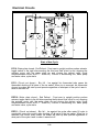
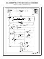
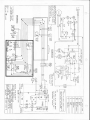
Electrical Circuits
The schematic wiring diagrams, provided on these pages, show the flow of electric
current at several steps in the operation of the ice maker. The dark lines show current
flow on all wiring diagrams. Following the diagrams is a description of the operation
specifically related to the circuits that are used at each step. These circuits apply to all
electronic and electromechanical ice makers built since 1964 and to those ice makers
in the field which have been revised to the 1964 wiring.
'EC' refer to Thermostatically controlled ice makers
'EEC' refer to Electronically controlled ice makers
Water Fill
EC1: Water fill (circulating water above 45} F.) - Current to condensing unit, water
pump and water valve. Water filling circulation tank and control tank. Water pump
circulating water through water header, distribution laterals and jet holes to individual
evaporator cells. Evaporator is cooling water (approximately 2 minutes).
EEC1: Water fill (circulating water above 45} F.) - Current to condensing unit, water
pump and water valve. Water filling circulation tank and water level probe assembly.
Water pump circulating water through water header, distribution laterals and jet holes
to individual evaporator cells. Evaporator is cooling water (approximately 2 minutes).
Kold-Draft® Service & Parts Manual
-13B-
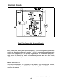
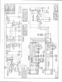
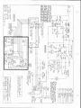
Electrical Circuits
Water Fill
EC2: Water fill (ice maker with cold water thermostat-circulating water below 40} F.) Current to condensing unit, water pump, water valve and through blue circuit through
cold water thermostat, pink circuit to defrost valve. When the incoming water is cold
and the compressor can cool the water below 40} F. during the 'Fill Cycle', the cold
water thermostat will switch to the cool side connecting the pink and blue circuits giving
power to the defrost valve allowing hot gas from the compressor to go through the
evaporator warming up the circulating water. GS models have no cold water
thermostat.
EC2a: Water fill (ice maker with cold water thermostat-circulating water warms up to
50} F.) - If the water warms up to 50 } F. before the water fill is complete and the weight
control switch drops, the cold water thermostat will switch to the warm side shutting the
defrost valve and the compressor will start to cool the water again.
EEC2: Water fill control (circulating water below 40 to 45} F.) - Current to condensing
unit, water pump, water valve and through blue circuit through cold water thermostat,
pink circuit to defrost valve. When the incoming water is cold and the compressor can
cool the water below 40} F. during the 'Fill Cycle', the cold water thermostat will switch
to the cool side connecting the pink and blue circuits giving power to the defrost valve
allowing hot gas from the compressor to go through the evaporator warming up the
circulating water.
EEC2a: Water fill control (circulating water warms up to 50 to 55} F.) - If the water
warms up to 50} F. before the water fill is complete and water touches the top
thermistor water level probe, the cold water control will switch to the warm side shutting
the defrost valve, and the compressor will start to cool the water again. A red L.E.D. is
mounted on the printed circuit card below the cold water control potentiometer as a
service aid. It is on (bright) when the cold water control is in the cold position.
Kold-Draft® Service & Parts Manual
-14B-
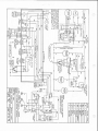
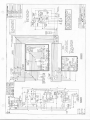
Electrical Circuits
Start of Freeze Cycle
EC3: Tanks full, weight switch drops (freeze cycle evaporator above 20 } F.) - Sufficient
water is in the circulation tank and control tank so that the weight of the water in the
control tank pulls the weight control switch down shutting the water valve. If the cold
water thermostat is still on the cool side and the circulating water is still being warmed
as the weight control switch drops, this switch cuts off power to the blue circuit and
through the cold water thermostat to the defrost valve shutting the defrost valve. Water
level should settle in the control tank at a preset distance below the top of the main
circulation tank. (Refer to the Water Levels, Pressures, Cycles and Charges chart.)
Current to condensing unit and water pump. Water freezing in cells. Springs hold water
plate edges against bottom of cams. Cams and hinge leaves hold water plate
approximately 1/32" from evaporator to adequate fin between the cubes.
EEC3: Tank and water level probe assembly full-freeze cycle evaporator above 26} F. Sufficient water is in the circulation tank and water level probe assembly so that water
touches the top thermistor probe and the water valve shuts off.
Kold-Draft® Service & Parts Manual
-15B-
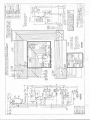
Electrical Circuits
Freeze Cycle
EC4: Freeze cycle with evaporator below 20} F. - During the freeze cycle, the
evaporator and the actuator thermostat get cold enough (approximately 20 } F.) to reset
the actuator control ready for the next defrost cycle. The particular time when this
happens is unimportant since the water control stays off and prevents defrost until the
cubes are full and the water is used up, and there is no change in the current flow at
this step. During this period the water is being used up in the formation of ice and the
water level drops slowly in the circulation tank and the water level probe tube.
EEC4: Freeze cycle with evaporator below 26} F. - During the freeze cycle, the
evaporator and the thermistor probe get cold enough (approximately 26} F.) to reset
the actuator control ready for the next defrost cycle. The particular time when this
happens is unimportant since the water control stays off and prevents defrost until the
cubes are full and the water is used up, and there is no change in the current flow at
this step. During this period the water is being used up in the formation of ice and the
water level drops slowly in the circulation tank and the water level probe tube. An orange
L.E.D. is mounted on the printed circuit card below the actuator control potentiometer as
a service aid. It is on (bright) when the actuator control is in the cold position.
Kold-Draft® Service & Parts Manual
-16B-
Electrical Circuits
End of Freeze Cycle- Start of Defrost
EC5: Start of defrost - Cubes are full and some have almost frozen over jet holes
forcing some of the remaining water faster through the control stream over the control
stream dam, lowering the water level rapidly in the control tank until it is light enough
for the weight control switch to snap up. Current flows to condensing unit, water pump,
through the weight control switch and the blue circuit to the water valve, also from blue
through the actuator thermostat, first connection is complete to the red defrost circuit.
From red, current flows through the actuator toggle switch giving 115 volts on the gray
actuator motor circuit; current through the capacitor which changes phase and boosts
the voltage to 200 volts on the yellow actuator motor circuit giving counter-clockwise
rotation. Current from the blue circuit flows through the cold water thermostat to the
pink circuit and defrost valve. Cams start rotating counter-clockwise pressing on the
cam brackets on the water plate to release it from the ice (approximately 15 seconds).
The open defrost valve allows hot refrigerant gas from the compressor to go through
the evaporator coil to start releasing the cubes.
EEC5: Start of defrost - Cubes are full and some have almost frozen over jet holes
forcing some of the remaining water faster through the control stream over the control
stream dam, lowering the water level rapidly in the water level probe assembly until the
bottom thermistor probe is exposed to air and trips the water level control on in 5-20
seconds. Current flows to condensing unit, water pump, through the weight level
control and the blue circuit to the water valve, also from blue through the actuator
control, first connection is complete to the red defrost circuit. From red, current flows
through the actuator toggle switch giving 115 volts on the gray actuator motor circuit;
current through the capacitor which changes phase and boosts the voltage to 200 volts
on the yellow actuator motor circuit giving counter-clockwise rotation. Current from the
blue circuit flows through the cold water control to the pink circuit and defrost valve.
Cams start rotating counter-clockwise pressing on the cam brackets on the water plate
to release it from the (approximately 15 seconds).The open defrost valve allows hot
refrigerant gas from the compressor to go through the evaporator coil to start releasing
the cubes.
Kold-Draft® Service & Parts Manual
-17B-
Electrical Circuits
Defrost
EC6: Water plate lowering - The pump and defrost switch lever drops, stopping the
pump and completing the second connection to the red defrost circuit. The actuator
motor and cams continue to rotate counter-clockwise lowering the water plate. The
open water valve allows water to begin rinsing off the water plate. Current to the
condensing unit, actuator motor, water valve and defrost solenoid (approximately 20
seconds).
EEC6: Same as EC6
Kold-Draft® Service & Parts Manual
-18B-
Electrical Circuits
Defrost
EC7: Defrost - Water plate is wide open and actuator toggle rod on the actuator motor
coupling pushes the actuator toggle switch to the left, stopping the motor with the water
plate in the 'down' position and completing the third connection to the red defrost
circuit. Current to the condensing unit, water valve and defrost solenoid. Excess water
concentrated with minerals, drains from the water tank. Freshes water washes water
plate and tank. Hot refrigerant gas continues flowing through the evaporator releasing
the ice slowly. Edge of the evaporator and actuator thermostat bulb remain cool (32 to
35} F.) as long as ice remains in the evaporator (approximately 2 to 4 minutes
depending on ambient and hot gas temperature). Ice releases on the left side first and
rests on the water plate, then the ice falls out substantially all at one time as the fin
between cubes tends to hold them together until they drop into the bin. After ice falls
out, the side of the evaporator warms up rapidly to 45} F. (approximately 30 seconds).
The actuator toggle pushed left also completes yellow/orange circuit but with no power
in the orange circuit, the actuator motor gets no power during the defrost period.
EEC7: Defrost - Water plate is wide open and actuator toggle lever on the actuator
motor rear shaft pushes the actuator toggle switch to the right, stopping the motor with
the water plate in the 'down' position and completing the third connection to the red
defrost circuit. Current to the condensing unit, water valve and defrost solenoid. Excess
water concentrated with minerals, drains from the water tank. Freshes water washes
water plate and tank. Hot refrigerant gas continues flowing through the evaporator
releasing the ice slowly. Edge of the evaporator and evaporator probe remain cool (32
to 35} F.) as long as ice remains in the evaporator (approximately 2 to 4 minutes
depending on ambient and hot gas temperature). Ice releases on the left side first and
rests on the water plate, then the ice falls out substantially all at one time as the fin
between cubes tends to hold them together until they drop into the bin. After ice falls
out, the side of the evaporator warms up rapidly to 45} F. (15-30 seconds). The
actuator toggle pushed right also completes yellow/orange circuit but with no power in
the orange circuit, the actuator motor gets no power during the defrost period.
Kold-Draft® Service & Parts Manual
-19B-
Electrical Circuits
End of Defrost-Water Plate Starts Closing
EC8: Water plate starts closing - Warm actuator thermostat bulb on the side of the
evaporator switches actuator thermostat from cold position disconnecting the first
circuit to red; the current from black/green to the red circuit continues through the
actuator toggle and pump toggle switches. The actuator thermostat switching to the
warm position completes the red/orange circuit and through the actuator toggle gives
115 volts to the yellow winding on the actuator motor. The capacitor changes the phase
and boosts the voltage to 200 volts to the gray winding of the motor to give clockwise
rotation. Cams rotating clockwise pull up the springs and water plate. Current to
condensing unit, defrost water valve and actuator motor (approximately 20 seconds).
The cold water thermostat bulb on the edge of the evaporator will warm up at about this
time or during closing and switch the cold water thermostat to the warm side connecting
the red to the pink circuit; since red is energized, the defrost valve stays open.
EEC8: Water plate starts closing - Warm evaporator probe on the side of the
evaporator switches actuator control from cold position disconnecting the first circuit to
red; the current from black/green to the red circuit continues through the actuator
toggle and pump toggle switches. The actuator control switching to the warm position
completes the red/orange circuit and through the actuator toggle gives 115 volts to the
yellow winding on the actuator motor. The capacitor changes the phase and boosts the
voltage to 200 volts to the gray winding of the motor to give clockwise rotation. Cams
rotating clockwise pull up the springs and water plate. Current to condensing unit,
defrost water valve and actuator motor (approximately 20 seconds). The cold water
control will warm up at about this time or during closing and switch to the 'warm' side
turning off the red L.E.D. Models with GBB-03135-02-E P.C. cards will turn off the hot
gas valve at this time, regardless of the water plate position. Refer to model wiring
diagrams for circuit details.
Kold-Draft® Service & Parts Manual
-20B-
Electrical Circuits
End of Defrost-Water Plate Finishes Closing
EC9: Water plate almost closed - Lift plate pushes up the pump and defrost toggle
switch, starting pump and disconnecting the second circuit to red, but current from
black/green to red continues through actuator toggle switch. Current to all operating
parts of the cuber. Water starting to fill the tank. Hot gas from the defrost valve keeps
the evaporator warm to melt any small piece of ice that may be left on the water plate
as it closes. Cams continue rotating to upright position (approximately 5 seconds).
EEC9: Same as EC9
Kold-Draft® Service & Parts Manual
-21B-
Electrical Circuits
Start of New Cycle
EC10: Water plate closed - End Defrost - Front cam in upright position pushes actuator
toggle switch to the right disconnecting the third and final circuit to red, stopping the
actuator motor with the water plate up and closing the defrost valve (cycle
completed-same circuit as EC1 - Water fill). Current to condensing unit, water pump
and water valve, cycle starts.
EC11: (Circuit not shown) - Bin full - Ice against bin thermostat tube opens bin
thermostat shutting off all parts of the ice maker. When ice is removed, bin thermostat
closes; ice maker will start up and operate regardless of what part of the cycle it was in
when it was shut off.
EEC10: Water plate closed - End Defrost - Front cam in upright position pushes
actuator toggle switch to the left disconnecting the third and final circuit to red, stopping
the actuator motor with the water plate up and closing the defrost valve (cycle
completed-same circuit as EC1 - Water fill). Current to condensing unit, water pump
and water valve, cycle starts.
EEC11: (Circuit not shown) - Bin full - Ice against bin probe after water fill cycle is
completed, opens bin control relay shutting off all parts of the ice maker. When ice is
removed, bin control relay closes; ice maker will start up and operate regardless of
what part of the cycle it was in when it was shut off.
Kold-Draft® Service & Parts Manual
-22B-
Electrical circuits
Abnormal Opening of Water Plate
EC12: Abnormal opening of water plate - Sometimes a cube may stick to the water
plate while it is closing (EC8) and by stretching the springs, prevents the water plate
from closing enough to push the pump and defrost toggle switch up as it normally does
(EC9). The circuit through the pump and defrost toggle switch will remain complete to
the defrost 'red' circuit to the lowering (counter-clockwise) side of the actuator toggle
switch so that, when the front cam pushes the actuator toggle switch to the right, the
actuator motor will immediately reverse and, with cams rotating counter-clockwise, the
water plate will re-open. Current to condensing unit, water valve and through the pump
and defrost toggle switch to the actuator motor. Any other obstruction between the
water plate and the evaporator can cause the same effect as a cube on the water plate .
If the collar on the pump and defrost switch lift rod is set incorrectly so the switch will
not go all the way up, abnormal opening will occur. Further, if the water level is set
much too high and/or spring is unhooked, allowing the water plate to sag during the
water fill so that the defrost switch goes down, the circuit will be completed to the
actuator motor and the plate will open. Likewise, abnormal opening can be created
during the water fill or the beginning of the freeze cycle if the water plate is pulled down
by hand, stretching the springs until the pump and defrost switch goes down,
completing the circuit to the actuator motor. This is done to rinse the ice machine after
using ice machine cleaner. Opening by hand is also used to observe the jet streams by
allowing the cams to go down to horizontal, then pushing up on the pump toggle rod.
Further opening by hand allows a quick partial check of the weight control switch as the
water drains from the control tank and the switch snaps up with a small amount of water
left in the tank (during this check the the control tank tube, it must be a full 11" long to
prevent binding between the control tank and the control stream box on the water
plate).
EEC12: Same as EC12
Kold-Draft® Service & Parts Manual
-23B-
Electrical Circuits
Water Plate Closing After Abnormal Opening
EC13: Water plate closing after abnormal opening - Since the evaporator and actuator
control are warm during abnormal opening, a circuit is complete through the actuator
control to the orange circuit of the actuator toggle switch. As soon as the water plate is
wide open and the actuator toggle rod on the motor coupling pushes the actuator
toggle switch to the left, the motor will immediately reverse and with cams turning
clockwise, close the water plate.
EEC13: Same as EC13
If the obstruction remains, EC12 and EC13 will repeat. If the obstruction is removed,
such as the cube falling out, EC13 will be followed by EC9 and EC10 and normal
operation will resume.
Kold-Draft® Service & Parts Manual
-24B-
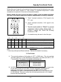
Speedy Functional Tests
Without the use of special tools or testers, these tests can quickly determine any major
faults with the control module P.C. card, probes, or functional components. A small
screwdriver is required to fit the slots on the potentiometers.
Before starting the test, be sure that there is power to the ice maker and check
the fuses in the control module box and the supplemental line fuses (if installed).
A
"Open" terminals simulate a 'Cold' signal to the
P.C. card.
B
"Short" terminals simulate a 'Hot' signal to the
P.C.card.
C
Turn the wash switch to "Wash" to prevent
compressor short cycling during tests. To
perform a speedy test, induce the following
conditions on TB2.
D
A screwdriver may be used to short the pins.
B
E
W
L
H**
Open
Open
Open
Open
Open
Cuber stops, Orange and Red L.E.D.'s ON bright
Short
Open
Open
Open
Open
Cuber runs, Orange and Red L.E.D.'s ON bright
Short
Short
Open
Open
Open
Cuber stops, Orange and Red L.E.D.'s OFF (may glow dimly)
Short
Open
Open
Short
Open
Harvest begins (allow plate to open fully), both L.E.D.'s ON bright
Open
Short
Open
Open
Open
Press relay #1 plunger*, water plate closes, both L.E.D.'s OFF or
dim
* If Relay #1 plunger is not accessible, CAREFULLY jumper the CONTACTS (B to
B/G)
** Used only with optional Status Indicator. See text for details if necessary.
To Test Probes
A
The nominal resistance of all probes at +32 o F is 5650 ohms. The only practical
accurate method is to test resistance of the probe in ice water (as near to +32o
F as possible). The ranges of acceptable resistances are :
Probe
Acceptable Range
Bin (GBR-03177)
5400-5900 OHMS
Evaporator (GBR-03176)
5530-5770 OHMS
Water Level (GBR-03170)
4650-6650 OHMS
B To ROUGHLY test probes using the P.C. card, connect each probe in turn to the
'E' pins with all other pins left open. Turn the cold water potentiometer to
mid-range (12 O'clock). A warm probe will turn BOTH L.E.D.'s 'OFF'.
Submerging the probe in ice water will turn the RED L.E.D. 'ON'. Reaction time
is 5-20 seconds. Be sure to return the cold water potentiometer to its original
position after the probe tests.
Kold-Draft® Service & Parts Manual
-25B-
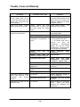
Trouble, Cause & Remedy
Note: Common to Electronic and thermostatically controlled cubers (regular type)
Electronic only (bold type)
Thermostatically controlled cuber only (italicized type)
TROUBLE
Cuber will not start
CAUSE/SYMPTOM
REMEDY
Line fuse blown
Check circuit for short
ground. Replace fuse.
Bin full of ice
Open circuit in cord or feed
wires.
No money in meter if meter is
used.
Room too cold (below 45 deg.
F.)
Overheated evaporator.
Blown fuse on PC card.
Bin probe disconnected or
loose.
Bin potentiometer in full
counter-clockwise position.
Defective bin probe
Shorted evaporator probe.
Bin relay coil
Condensing fan operating but
not the compressor.
Defective PC card.
Compressor stuck or defective.
Defective capacitors or relay.
Defective overload switch.
Open wash switch.
Compressor operating but not
the condenser fan.
Condenser fan operating, but
the condensing unit is operating
intermittently during the freeze
cycle. Determine if the unit
returns to normal operation at
the end of the defrost cycle.
Open high or low pressure
cut-out.
Circuit not complete.
Fan motor defective.
Dirty condenser coil.
Low Voltage
Refrigerant overcharge
Fuse blown one leg of 3-wire
electronic system.
Repair or replace.
Warm room. Consult factory
for cold room application.
Check defrost circuit.
Replace fuse.
Install bin probe properly.
Adjust clockwise (colder)
Check probe resistance.
Check probe resistance.
A good coil has 100 ohms
resistance.
Replace
if
defective. Check wiring.
Test PC card.
Jar with mallet. Replace if
defective.
Replace capacitor or relay.
Repace overload switch or if
internal, replace compressor.
Switch to “Ice” position or
replace if defective.
Check charge and condenser.
Check wiring.
Replace motor.
Clean coil.
Correct to proper voltage, not
less than 5% below that stated
on nameplate.
Reduce the charge
Replace fuse.
Kold-Draft® Service & Parts Manual
-26B-
or
Trouble, Cause & Remedy
TROUBLE
Compressor cuts out.
CAUSE/SYMPTOM
REMEDY
Defective run capacitor.
Open high or low pressure
cutout.
Water plate opens and closes
constantly. Water plate closes
all the way when cams are up,
but defrost valve stays open
and pump does not run.
Maladjusted pump & defrost
switch.
Water plate does not close all
the way.
Water plate opens before water
probe assembly tube or weight
control tank is full.
Spring missing or springs
weak, allowing water plate to
lower slightly, as water fills
tank, until the pump switch
drops and the plate opens
under power.
Adjust lift bolt on water plate
to push switch lever up,
closing the hot gas valve
and starting the pump when
the water plate is up.
Adjust the lift rod collar to push
the pump switch up, closing the
hot gas valve and starting the
pump when the waterplate is
up
Remove
any
obstruction.
Adjust hinge for proper water
plate gap. Confirm that water
plate brackets are tight against
cams. Ckeck springs.
Replace springs.
Drift stop not adjusted. Cams
drift counter-clockwise until the
water plate lowers enough to
drop the pump switch.
Remove drift stop from the
front of the actuator motor.
Bend the spring for more
tension on the motor shaft.
Slow water fill.
Improve water supply. Clean
strainer.
Adjust cold water control on
PC card. Test evaporator
probe and PC card.
Adjust or replace actuator
thermostat.
Orange and Red
bright on PC card.
L.E.D.s
Actuator thermostat out
adjustment or defective.
Water plate will not completely
close.
Run capacitor should draw 1 to
3 amps. GB2 & GB4, 4 amps.
Check refrigeration system
pressure.
of
Obstruction
between
the
evaporator and water plate.
Lift bolt, for pump toggle on
water plate, is too high,
holding the water plate away
from the cams.
Collar on lift rod too low,
holding the water plate away
from the cams.
Kold-Draft® Service & Parts Manual
-27B-
Remove obstruction.
Check
clearance between the water
plate and evaporator.
Adjust lift bolt so the water
plate comes up against the
cams while the lift bolt holds
the pump switch up.
Adjust collar so the water plate
comes up against the cams
while the lift rod holds the
pump switch up.
Trouble, Cause & Remedy
TROUBLE
Water plate
cubes drop.
closes
before
CAUSE/SYMPTOM
REMEDY
Actuator pot on PC card
adjusted too cold.
Adjust to warmer position
(ccw).
Waterplate should
remain down 10 to 30
seconds after ice drops.
Test probe resistance.
Test PC card
Adjust to a warmer position
(ccw). Water plate should
remain down 10 to 30 seconds
after ice drops.
Straighten fins.
Adjust the actuator control
slightly clockwise. Test the
evap. probe and PC card.
Check wiring.
Replace
actuator toggle switch.
Faulty evaporator probe.
Faulty PC card.
Actuator thermostat adjusted
too cold.
Water plate stays wide open
after defrost and all ice is out of
the evaporator
Bent evaporator fins.
Orange L.E.D. stays lit on PC
card.
Orange L.E.D. is off, but no
voltage
to
the
yellow
actuator motor lead.
No voltage to #3 (orange lead)
of actuator thermostat.
Water plate open, but
evaporator will not defrost.
Voltage to #3 (orange lead) of
actuator thermostat, but no
voltage to yellow actuator
motor lead.
Refrigerant charge low.
Inadequate hot gas volume.
Defective hot gas valve.
Red L.E.D. is on.
Red L.E.D. is off.
Cold water thermostat
making contact.
Water pump does not operate.
not
Fuse blown in transformer box
or in control module box.
Pump bearings defective.
Pump windings burned out or
off on thermal overload.
Circuit incomplete between
water pump and pump-defrost
switch.
Actuator thermostat adjusted
too warm or bulb has lost
charge.
Wiring loose or defective
actuator toggle switch.
Check for leaks and recharge.
Check for tube obstruction or
cold condenser.
Replace valve or coil.
Check voltage at defrost
valve coil. If not 115 V. test
PC card.
Check evaporator probe and
PC card.
Tap cold water thermostat or
short across pink and red
leads. If defrost valve opens,
change thermostat.
Replace fuse
Replace pump motor.
Allow to cool, or replace motor.
Check for 115 V., plus or minus
10%
Check circuit and switch.
Kold-Draft® Service & Parts Manual
-28B-
Trouble, Cause & Remedy
TROUBLE
CAUSE/SYMPTOM
REMEDY
Water pump motor running but
not pumping water.
Impeller loose.
Clogged strainer in tank outlet.
Impeller broken.
Water pump pressure too low
Replace impeller.
Clean or replace strainer.
Replace impeller.
Check bearings.
Check
voltage. Replace pump.
Clean or replace strainer.
Fix leak or replace water plate.
Most cubes not fully formed.
Holes in left side cubes.
Clogged strainer in tank outlet.
Leak in water circulation
system
Waterplate not aligned with
evaporator.
Some holes in waterplate
clogged.
Superheat too low.
Holes in right side cubes.
Superheat too high.
Holes in all cubes sometimes
but solid cubes most of the
time.
Power shut off while water is
filling tank or temporary power
loss near the end of the freeze
cycle.
Bin control turns cuber off
during water fill.
A few cloudy cubes, others OK
Bin thermostat turns cuber off
during water fill.
Holes in cubes all of the time.
Control stream does not go
over the dam at the end of the
freeze cycle.
Water level too low.
Lower water level probe too
high.
Kold-Draft® Service & Parts Manual
-29B-
Correct alignment.
Open holes with 1/16” drill.
Flush laterals.
Close TXV in 1/8 turn
increments until corrected.
Open TXV in 1/8 turn
increments until corrected.
Correct power source.
Interlock between water fill
control and bin control not
operating. Check PC card.
This condition can happen
occasionally on any cuber, but
the frequency can be reduced
by
adjusting the bin
thermostat
warmer
(counter-clockwise).
The
machine will then turn off more
quickly when ice contacts the
bulb.
Test by applying ice
cubes to the bulb tube. The
machine should restart within
five minutes.
Measure from the top edge of
the water tank down to the
water level in the water level
control tube. Sight carefully
across the water in the control
tube. See “Chart of Water
Levels, etc.” Increase water
level if required.
Adjust water level probe to
remain immersed in water in
control tube at least 10
seconds after the control
stream starts going over the
dam.
Trouble, Cause and Remedy
TROUBLE
Holes in cubes all of the time.
Control stream does not go
over the dam at the end of the
freeze cycle. (Continued from
previous page.)
Holes in all cubes. Control
stream does go over the dam.
Cuber will not harvest. Water
plate will not come down.
CAUSE/SYMPTOM
REMEDY
Leak in water system
Control
stream too high
allowing water to splash over
the dam during the freeze
cycle.
Control stream obstructed.
Actuator motor problem.
Warm air infiltration from
compressor compartment or
room.
Orange L.E.D. does not
come on.
Orange L.E.D. does not
come on, but probe is good.
Inoperative lower probe.
Cubes do not harvest in a slab.
Some cubes hang up in the
evaporator
and
become
distorted.
Slab does not break up into
individual cubes.
Control tank will not snap up
Actuator thermostat out of
adjustment.
Defective
actuator
toggle
switch.
Power supply has failed.
Fin too thin.
Deformed evaporator cells.
Fin too thick.
Water dripping steadily off the
circulation tank indicates a leak
which should be located and
repaired. Make sure all lateral
plugs are in place.
Lower control stream. Turn
adjusting screw clockwise.
Loosen adjusting screw to flush
out foreign matter.
Check motor and circuit.
A. Secure all skin panels.
B. Skin gaskets must seal.
C. All panels must seal to
prevent
air
from
the
compressor
compartment
getting into the ice making
compartment. Check top cover
over the partition especially.
Check
evaporator
probe
resistance.
Test PC card.
Check water level probe
connections.
Test probe
resistance. Test PC card.
Adjust switch differential.
Adjust
slightly
counter
clockwise.
Replace switch.
Restore power.
Adjust waterplate hinges to
1/32” fin thickness.
Straighten cells with smooth
jaw pliers.
Adjust hinges up or evaporator
down.
Leave 1/32” space
between the waterplate and
evaporator.
Kold-Draft® Service & Parts Manual
-30B-
Trouble, Cause and Remedy
TROUBLE
Unusually long cycles.
CAUSE/SYMPTOM
REMEDY
Voltage
below
required
potential at the cuber.
Check power source for full
voltage. Run minimum 12 GA.
wire directly to the cuber to
prevent line loss.
Clean condenser.
All skin panels must be tightly
sealed.
Dirty condenser.
Hot
air
leaks
between
condensing unit compartment
and freezing compartment.
Expansion valve too far open.
Expansion valve too far closed
with large holes in right side
cubes.
Water level too high.
Refrigerant low.
Compressor defective.
Control stream too low.
Fan not operating.
Some cubes do not form in the
right side corners of the
evaporator.
Spray holes at the ends of the
laterals are frozen shut and will
not thaw because of very low
incoming water temperature.
Ice freezes to water plate
causing shear pins to break.
Water fill level too high.
Incorrect clearance between
the water plate and evaporator.
Misadjusted control stream.
Control stream will not go over
dam at the end of the freeze
cycle.
Water
plates
out
of
synchronization
on
GB4,
GB903, GB1003 or GB1205
cubers.
Kold-Draft® Service & Parts Manual
-31B-
Close TXV in 1/8 turn
increments so that there is no
frost back to the compressor
and pressures are according to
the “Chart of Water Levels,
etc.”
Open TXV in 1/8 turn
increments. Recheck to see
that there is no frostback to the
compressor at the end of the
freeze cycle.
Adjust water level according to
“Chart of Water Levels, etc.”
Check for and repair leak. Add
refrigerant as required.
Replace compressor.
Adjust control stream.
Check fan wires, replace motor
if necessary.
Thaw out by shutting off unit
and adjust the cold water
control warmer (CCW). Adjust
expansion valve 1/8 turn
closed.
Adjust fill level per “Chart of
Water Levels, etc.”
Adjust water plate and/or
evaporator as required.
Adjust control stream.
Cracked water plate causing
pressure loss.
Repair or
replace water plate.
See GB900/GB1000 section.
Trouble, Cause and Remedy
TROUBLE
Water valve stays closed.
Water valve stays open after
water covers the upper probe
tip. Will not shut off.
Water valve stays open more
than 5 seconds after water
covers the upper probe tip.
CAUSE/SYMPTOM
REMEDY
Water level probe connector
loose or dirty.
Clean connector and install
properly. Low probe lead to
right.
Use NC123 or any
electrical contact cleaner.
Check probe resistance.
Defective
water
probe
assembly.
Circuits okay, 115 volts to
water valve. Coil open. Flow
control jammed or cockeyed.
Defective PC card.
Water level probe connector
loose or dirty.
Defective
water
probe
assembly.
Defective PC card.
Water pressure below 15
P.S.I.
Defective water valve.
Upper probe covered with
scale.
Replace coil,
clear valve
passages or replace valve.
Test PC card.
Clean connector and install
properly. Low probe lead to
right.
Use NC123 or any
electrical contact cleaner.
Check probe resistance.
Test PC card.
Increase water pressure to
ice machine.
Replace water valve.
Clean cuber with ice machine
cleaner.
If
necessary,
remove and clean probe
carefully.
Kold-Draft® Service & Parts Manual
-32B-
Service and Troubleshooting
GB900/GB1000/GB1200/GB4
These ice makers differ from other Kold-Draft® ice makers in that two ice making
sections are refrigerated by one condensing unit. GB900/GB1000/GB1200 series are
electronic versions of the GB4.
The upper ice making section, also known as the "master," contains the controls
necessary to operate both sections simultaneously, while the lower or "slave" section
contains only those switches required to operate the actuator motor and water pump,
and to provide synchronization between the two water plates.
The GB4 uses an electrical synchronization system to ensure that both water plates are
fully closed before the freeze cycle begins, and to prevent repeated false harvesting
caused by "out of time" actuator motors.
There are two key parts in the synchronization system. A modified rotor in the top
actuator motor to slow the motor by 5 seconds, and a resistor between the upper and
lower actuator toggle switches to stall the lower motor in the closed position at the end
of harvest.
Synchronization is achieved by the lower actuator motor running slightly faster than the
upper motor, stalling upon direction reversal in the full upright (12 O'clock) position,
thus allowing the upper motor to catch up and synchronize. Upon upper motor direction
reversal, both motors continue to the end of the travel limit in the other direction and
repeat the same synchronization procedure. With ice in the evaporators, both plates go
down and stop together in the full down position automatically synchronized. When dry
cycling the cuber without ice, the lower actuator motor trips the lower actuator toggle
switch and raises ahead of the upper actuator motor. Synchronization occurs when the
lower actuator motor stalls after raising to the 12 O'clock position and waits for the
upper actuator motor to catch up.
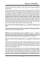
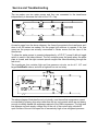
This diagram shows the synchronization
circuit. The dotted
lines indicate an
interim sub-circuit which was used from
9-81 until 1-83. To update any GB4, cut
the yellow/white in the upper channel,
tape the ends and install a modified rotor
kit (GBR-03110-01) in the upper actuator
motor. Cubers made before 9-81 do not
have the yellow/white wire in the upper
channel (unless they have been field
modified) and only the modified rotor is
required for updating.
Kold-Draft® Service & Parts Manual
-33B-
Service and Troubleshooting
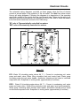
The ice maker use two water pumps and they are connected to the transformer
independently to decrease the load on the 115 v. tap.
As can be seen from the above diagram, the 4-amp fuse protects the transformer as it
does in all GB series ice makers, but the pumps will continue to operate if the fuse
opens as the pumps are actually connnected in Series across the line taps of the
transformer.
To allow the water pumps to operate independently, a D.P.D.T. pump & defrost toggle
switch is used in the lower channel. The left contacts power the pump when the water
plate is closed, and the right contacts permit caught-cube false harvesting through the
red circuit.
The transformer box contains high and low pressure cut-outs, as do all 1 H.P. and
larger Kold-Draft® cubers, and also a high and low cut-out relay.
The above diagram illustrates the cut-out circuitry, and shows that compressor current
is controlled by a heavy-duty relay rather than the cut-out contacts which are not heavy
enough to reliably handle the amperage required of the GB4 compressor. The high and
low pressure cut-outs supply voltage only to the coil of the control relay, which will
open if either of the cut-outs open due to excessively high or low refrigerant pressure.
Kold-Draft® Service & Parts Manual
-34B-
Service and Troubleshooting
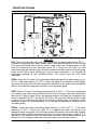
The ice maker contains two evaporators and therefore two expansion valves, but only
only one hot gas defrost valve.
As can be seen by the simplified refrigeration diagram above, the hot gas defrost
tubing from each evaporator is joined at the hot gas valve, and provides a refrigeration
circuit (during the freeze cycle) between the evaporators. As the evaporator inlet
pressures are never exactly equal, refrigerant can flow from one evaporator inlet to the
other through the hot gas tubing, causing frost on the tubing. To the service man not
familiar with the GB4, this can be a startling phenomenon (hot gas lines are not
supposed to be cold). but is perfectly normal and has little or no effect on the operation
of the cuber. To minimize frost on the hot gas tubing (which turns to water during the
defrost cycle) a ball check valve was added 8-82 to the hot gas line feeding the upper
evaporator. During harvest, the check valve opens fully and allows unrestricted hot gas
to both evaporators. During the freeze cycle the upper evaporator expansion valve,
which is set at a slightly lower superheat than the lower expansion valve, will cause the
check valve to close and block refrigerant flow through the hot gas tubing.
Theoretically, both expansion valves can be set at the same superheat, as the
gravity-operated ball check valve requires approximately 1/4 p.s.i. to unseat. Hot gas
line frost will not occur as long as the inlet pressure in the upper evaporator is equal to
or greater than the inlet pressure in the lower evaporator.
Kold-Draft® Service & Parts Manual
-35B-
Service and Troubleshooting
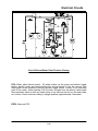
GB1204/GB1205
The GB1200 series cubers are derived from the GB903/GB1003 series ice makers, and
therefore share the same synchronization circuits, water pump control wiring and
refrigeration circuit.
The compressor used in the GB1205 series is 208/230 volt-60 hz.-3 phase. The
GB1204 series uses a 208/230 volt-60 hz.-1 phase, and therefore uses a line contactor
for compressor operation. The following diagram illustrates the contactor circuit, and
also shows the transformer connection to provide single phase 115 volt power for the
water pumps and solenoid valves.
Although the refrigeration circuit is identical to the GB4/GB903/GB1003, the
compressors in the GB1200 series use R-502 refrigerant along with R-502 expansion
valves.
Kold-Draft® Service & Parts Manual
-36B-
Service and Troubleshooting
Actuator Motor Electrical Tests
The following tests are for troubleshooting the actuator motor and related circuits:
Use an AC voltmeter set for proper range. Voltages in the tables are measured across
the motor reversing capacitor (between the colored motor lead wires).
> If there is no ice in the evaporator(s) and the water plate(s) is (are) not fully closed
with the pump(s) running AND the actuator switch(es) tripped UP, the actuator motor(s)
should be running. If not, be sure that there is power to the motor(s) and that it (they)
is (are) not off due to high temperature (NEW STYLE). Always refer to the proper
wiring diagram when troubleshooting.
> In dual evaporator models if only one motor appears to be running as it should, be
sure that you understand the synchronization circuit (see text).
> For OLD STYLE motors in 208-230/60 or 220-240/50 CLASSIC cubers, the voltage
between the white motor lead (connected to the voltage reduction capacitor) and the
colored lead (gray or yellow) being powered by the actuator switch must be 90 to 130
volts. This varies with line voltage, and if not within these limits the motor(s) may not
provide adequate performance. Be sure that the proper capacitor is installed (see
text).
> Motor winding resistance's at 75o F out of the circuit are as follows:
All OLD STYLE motors, white to gray or yellow, approximately 450 ohms.
NEW STYLE 115 volt motors, white to black or yellow, approximately 95 ohms.
NEW STYLE 230 volt motors, white to red or yellow, approximately 400 ohms.
Actuator Motor Style
OLD STYLE, ALL
NEW STYLE, 115 VOLT
NEW STYLE, 230 VOLT
Voltages for test table below
"A"
"B"
180-240
90-130
180-240
LINE
290-370
LINE
Voltage Reading
Capacitor
Motor
Remedy
"A" from table
Good
Good
"B" from table
"B" from table in one actuator switch
position, 0 v. in the other position
"A" from table in one actuator switch
position, 0 v. in the other position
0 v. in both positions EXCEPT DUAL
EVAP. SLAVE DURING NORMAL STALL.
Be sure there is power to the motor ("B"
from table) by leaving one probe on either
capacitor lead and placing the other probe
on the white motor lead. If power is OK:
Open
Open
AND>
Good
Tap gearcase to align bearings; check
cam shaft for binding; check drift stop
tightness. Change motor if all OK.
Change capacitor.
Change both motor and capacitor.
Shorted
OR>
Good
One Motor
Winding open
One Motor Change motor.
Winding open
Both Motor Disconnect motor from circuit and
Windings open test winding resistance's (see text). If
normal, change the capacitor, and if
erratic change the motor.
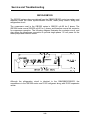
Testing C/R-C Network GB-3244 (electronic cubers only)
CAUTION: To protect your meter, short all terminals together before testing.
1- Set ohm meter on R x 1000 (1k) scale.
2- W to G- Connect test leads. Reverse test leads and the meter should deflect. A good component will
cause the meter to drop to about 200k ohms and then climb back to infinity.
3- G to Y- Connect test leads and then reverse. The meter should drop to about 150k ohms and then
climb back to infinity.
4- If the meter goes to the approx. ohm readings listed above and stays there, the capacitor is shorted
and
should be replaced.
5- If the meter doesn’t deflect at all, the capacitor is open and should be replaced.
Kold-Draft® Service & Parts Manual
-37B-
Service and Troubleshooting
Pump Intake Hose - Collapsing
1. If hose is too long or has been twisted, the tubing will collapse. These two
conditions can be corrected very easily by checking the length so that the
tubing is approximately 3-3/8" long, or by twisting the tubing to make certain it is
straight.
2. Dirty water tank outlet screen - In this instance, the tubing will collapse and
remain collapsed until the screen is cleaned. This could cause cloudy cubes,
because not enough water is being circulated.
3. Occasionally at the beginning of a cycle, if the water is super-cooled and
crystalization occurs in the water, the crystals would plug up the screen and
cause a collapse of the hose. This condition would last for less than a minute
until the crystals thaw and the ice maker would begin functioning properly. This
condition is not serious and would not damage any of the ice maker
components. The condition cures itself and is of short duration.
4. The hose may also collapse due to aging. The hose should be replace and a
spring (GBR-00212-01) installed.
Water Plate Problems
1. Improper setting of the fin thickness- Under tolerance fin thickness may cause
icing of injection and return holes, on the water plate surface. Refer to the
alignment page.
2. If the injection holes on the water plate become blocked, some of the freezing
cells will be devoid of ice at time of harvest. The blockage can be removed by
using a 1/16” drill bit to clean the injection holes. Note- Freezing cells void of
ice may collapse due to expansion of ice in surrounding cells.
3. If the injection holes are cleaned and water is still not flowing, then the laterals
have become clogged. To clean the laterals, remove the rubber plugs at the
end of the water plate. Run a small brush through the laterals and flush out all
debris. Place new plugs in the holes using an allen wrench or similar blunt end
tool. This stretches the plug so it will be tight when the tool is removed.
4. A crack in the lateral strips on the underside of the water plate may prevent the
control stream from rising up over the dam at the end of the freeze cycle. This
will extend the cycle and cause water to freeze into the surface of the water
plate. If the laterals are cracked, the water plate should be replaced.
5. Water plate silicone treatment- In certain areas, where water is unusually pure,
with practically no dissolved solids, the water plate must have fairly frequent
applications of silicone to prevent excessive ice adherence. Application of
silicone treatment is recommended every three months, or whenever the cuber
is serviced, where water conditions cause ice to stick to the water plate.
Kold-Draft® Service & Parts Manual
-38B-
Service and Troubleshooting
To Apply Silicone Treatment
Defrost the unit by lifting up on the control tank or pulling down on the water plate.
Place unit in the wash mode, allow the tank to refill to melt off any accumulated ice.
Open the water plate to dump out the tank.
Turn off the power with the water plate down. Wipe the water off the evaporator and
water plate surface.
Apply Kold-Draft water plate spray to the surface of the water plate except for the last
half-inch on the right side. This will keep water from running over the edge and into the
ice bin during defrost. Return unit to normal operation.
Note- Use Kold-Draft silicone water plate spray. Others may contain substances
detrimental to the water plate surface.
Removal of Water Plate and Tank
1. Turn off the water and allow the water plate to close. Turn off the power.
2. Remove the control stream drain hose.
3. Electronic cubers:
Remove the water level probe assembly by sliding it to the right, beyond the
control stream box and lifting it off. Disconnect the tube from the water tank.
Electro-mechanical cubers:
Remove the water control tank from the wire hanger. Disconnect the tube
from the water tank.
4. Remove the pump mounting screw holding the water plate brace. Remove the
inlet and outlet hoses from the pump.
5. Separate the hinge brackets from the water plate.
a. Cubers with plastic hinge brackets, pry the brackets away from the plate.
b. Cubers with metal brackets (prior to 1977), remove the four lower screws and
lock washers holding the water plate to the pump bracket and rear hinge.
Remove the nuts and lock washers holding the top of the water plate to the
pump bracket and rear hinge (5/16” socket).
6. Run the cam down to the nine o’clock position, by hand or with power. Unhook
the springs from the water plate.
Kold-Draft® Service & Parts Manual
-39B-
Service and Troubleshooting
7. Electronic cubers:
Remove the screws that mount the control module box. Pull the module
forward to disconnect the front cam. Rotate the module up for clearance.
Electro-mechanical cubers:
Remove the cotter pin from the pump toggle switch and remove the lift rod
and collar assembly.
8. Slide the water plate and tank to the right, without turning, and slide it forward
out of the machine.
Water Plate Assembly to Water Tank
1. Remove the spring bosses, water plate brace, water deflector, teflon brackets
and the four screws holding the water tank to the water plate.
Electronic cubers: Remove the pump and defrost actuation plastic bolt from
the water plate and assemble it to the new plate.
2. Attach the water tank to the water plate with four screws. Assemble the teflon
brackets, water deflector, water plate brace and spring bosses. Bosses should
be tight but care should be taken not to strip out the plastic threads.
Electro-mechanical cubers: Install the hinge screws and plates.
Reinstallation of Water Plate and Tank Assembly
1. With the open end of the water plate to the right, slide it back into the cuber and
to the left of its normal position.
Electro-mechanical cubers: Install the lift rod, cotter pin and collar assembly
with the small end of the crook to the right of the pump toggle switch.
2. Hook up the springs to the water plate. Rear spring first.
3. Plastic hinge brackets are hooked on and snapped in place.
For metal hinge brackets, holes must be drilled and tapped per drawing. Run
the top screws through the hinges, assemble the lock washers and nuts loosely.
Run the bottom screws through the hinges and into the plate, then tighten the
nuts and screws. It may be easier to reach the rear screws if the if the cams are
run up to the twelve o’clock position. See the following illustrations.
Kold-Draft® Service & Parts Manual
-40B-
Service and Troubleshooting
4. Secure the pump mounting screw holding the water plate brace. Install the inlet
and outlet hoses to the pump. Note: When installing the pump to tank hose, it
is usually easier to put it on the tank first, with one finger inside the hose, then
slip it onto the pump connection. Avoid any twist or kink. The hoses will slide
on easier if wet.
Kold-Draft® Service & Parts Manual
-41B-
Service and Troubleshooting
5.
Secure the water control assembly.
Electronic cubers: Mount the water level probe assembly and relocate the
control stream drain tube. Locate and secure the control module box to the
mounting bracket. Check adjustment of the lift bolt.
Electro-mechanical cubers: Reconnect the control stream drain tube and water
control tank.
6. Water plate must be properly aligned with the evaporator. Refer to the
alignment information provided. Adjust hinge plates and/or shim evaporator and
cam shaft bearing brackets to meet alignment specifications.
Kold-Draft® Service & Parts Manual
-42B-
Installation and Adjustments
Bin Probe Placement-Electronic Cubers
Bin Probe Placement-Electro-mechanical Cubers
Kold-Draft® Service & Parts Manual
-43B-
Installation and Adjustments
Air Cooled Condensers
1. Maintain adequate ventilation around the cuber. It is also important to prevent
re-circulation of the hot condenser air from the side to the back. This would
occur particularly if the condenser end were placed in a corner of a room. If this
must be the location, then an external air block should be built to prevent the
hot outlet air from returning to the inlet of the condenser.
2. Cleaning an air cooled condenser - The air cooled condenser should be
cleaned weekly with a stiff brush and a vacuum cleaner to remove dust and dirt
for efficient operation of the ice maker. To determine that tge condenser is
clean, a light which is held to one side of the condenser will be clearly visible
from the other side.
Water Cooled Condensers
1. Are factory set for 115 pounds pressure on all but GB1200 series (R-502) which
is set at 230-235 pounds head pressure. To reduce water consumption, head
pressure can be increased but ice capacity will be slightly reduced.
2. If head pressure is excessive and water usage is higher than normal, the
condenser must be cleaned.
3. Cleaning a water cooled condenser - Halstead Mitchell condensers have end
plates which may be removed for mechanical cleaning if necessary.
Water cooled condensers without end plates can be cleaned by flushing with a
condenser cleaning solution. Acid re-circulating pumps and solution are
available at refrigeration supply houses.
Kold-Draft® Service & Parts Manual
-44B-
Installation and Adjustments
Control Stream
When the cubes are fully frozen, they freeze over the drain holes in the water plate
surface. This increases the water pressure in the circulation system causing the
control stream to rise and then go over the dam. This water is drained off (15-30
seconds) until the level drops below the tip of the low probe. This causes the probe’s
resistance to change which is the signal to the card to initiate the harvest cycle.
Adjustment of the Control Stream
After the circulating water is cold, note the control stream and compare with the
following diagram. Adjust the stream to flow as in the illustration. (Note- As the water
cools it may actually sub-cool and form ice crystals in the water tank. This may last a
minute or two, temporarily stopping water plate circulation and the control stream. Do
not adjust the control stream at this time.)
If the control stream adjusting screw is changed at the end of the freeze cycle, to make
the stream go over the dam, recheck it at the early part of the next freeze cycle. Make
sure no water is flowing over the dam until all the cubes are ready for harvest.
Cube Quality
1. If the cubes are full with only small dimples (1/8”-3/16” deep), the amount of
water taken in at the start of the cycle is correct.
2. If the water level drops below the low probe and initiates the harvest cycle
before the control stream goes over the dam, then there was insufficient water
taken in at the beginning of the cycle, or there is a leak in the system. Cubes
with large holes are an indication of this problem. Adjust the high water level
probe up to increase the water intake on the next cycle or eliminate the leak.
Note: The leak may be internal such as a cracked lateral under the water plate.
Kold-Draft® Service & Parts Manual
-45B-
Installation and Adjustments
3. If the control stream goes over the dam for more than one minute before the
water clears the low probe and cubes are found to have large holes, then the
control stream is set too high. Set the control stream slightly lower at the start of
the next freeze cycle. If ice is frozen to the water plate, adjust the lower water
level probe up slightly so the harvest is initiated within 15-30 seconds of the
control stream rising over the dam.
4. Holes, in the cubes on only one side of the evaporator, indicate a refrigerant flow
problem.
Expansion valve models:
Holes in the left side cubes indicate the expansion valve is open too
much. Adjust the valve closed at 1/8 turn increments.
Holes in the right side cubes indicate the expansion valve is closed too
much. Adjust the valve open at 1/8 turn increments.
Capillary tube models:
Holes in the left side cubes indicate overcharge.
Holes in the right side cubes indicate undercharge.
Water Level Probe Assembly (GBR-03170)
This assembly is connected to the main water circulation tank by means of flexible
tubing. The level of water in the probe assembly indicates the level of the water in the
circulation tank. Thermister probes determine water valve on-off levels. Refer to the
chart of water levels for the correct position for the upper probe. The bottom probe is
positioned so that 15-30 seconds after the water flows over the dam, harvest is
initiated. Initially the tip of the probe should be set at approximately 1/2” to 3/4” from
the bottom of the tube.
Kold-Draft® Service & Parts Manual
-46B-
Preventative Maintenance
Cleaning: Usually at 3 to 6 months intervals, depending on water conditions.
Inspections: During cleaning - at least twice a year.
Service: All such equipment will require service at some time. Service requirements
will be minimized with faithful preventative maintenance including good housekeeping
at the installation site. A CALL FOR SERVICE AS SOON AS A POSSIBLE PROBLEM
IS NOTICED MAY AVOID EXTENSIVE REPAIRS.
Ice Cuber Cleaning Instructions
Use rubber gloves and eye protection. An apron is recommended.
GB & GT400, 500 and 600 series: Mix one bag of Kold-Draft® ice machine cleaner
(55R-01000) in (2) quarts, or GS, GY or GT300: Mix 1/2 bag of Kold-Draft® ice
machine cleaner (55R-01000) in (1) quart of clean, warm water (180} F. MAX.) for
each evaporator/water plate assembly to be cleaned.
2. If the cuber is operating, wait until a harvest cycle occurs then trip the ‘WASH' switch
to 'WASH' as soon as the water plate begins to close.
3. Empty all ice from the storage bin and shut off other ice makers on the same bin.
4. After the water fill is completed, remove the cap from the water level control and pour
about half of the mixed cleaner into the control tank or tube tube. Caution: In
electronic cubers, do not remove the water level probe assembly completely, or
lower the control tube far enough to overflow. Replace the cap, then pour the
remaining cleaner into the control stream box.
5. Allow the cleaner to circulate for approximately 15 minutes, then pull the right side of
the water plate down until the pump stops and hold it until the pump will not re-start
when released.
6. The water plate will open and dump the cleaner then close immediately, and the
water system will refill. Repeat this dumping and refilling three (3) times to rinse out
all of the cleaning solution.
7. Mix a sanitizing solution of two (2) oz. 5-1/4% sodium hypochlorite (household bleach
or equivalent) and one (1) quart clean water.
8. As in step #4, pour about half of the sanitizing solution into the water level control
tank or tube and the remaining sanitizer into the control stream box.
9. Allow the sanitizing solution to circulate AT LEAST 15 MINUTES, then dump and
rinse two (2) times as described above. If necessary, reset the water level probes to
the proper levels.
10.While the cleaning and sanitizing solutions are circulating, clean, rinse and sanitize
all accessible parts of the ice-making compartment of the cuber with clean cloths.
Use a cleaning solution of 8 tablespoons (1/2 cup) baking soda per gallon of warm
water, and a sanitizing solution of no less than 1 teaspoonful (5 ml.) 5-1/4% sodium
hypochlorite per quart of clean water.
11.After cleaning has been completed, trip the 'WASH' switch to 'ON' and check to be
sure that the cuber is operating properly, particularly the water level probes. Then
re-assemble and secure all cabinet enclosure panels.
1.
Kold-Draft® Service & Parts Manual
-47B-
Preventative Maintenance
Ice Bin Cleaning Instructions
The bin should be cleaned periodically. If bin drain has any horizontal run, remove ice
from left side of bin and flush with two (2) quarts of hot water monthly. (Long drain lines
should be flushed weekly.)
Clean exterior of bin frequently.
2. To clean the interior, follow the instructions provided with bin.
3. Empty the storage area and disconnect the electrical power supply to the ice
maker(s).
4. Remove the ice maker inspection panel, top, left and right end panels, and drain pan.
Sliding bin doors may be removed by lifting them up, then pulling out from the bottom.
5. When cleaning the ice maker, follow the ice maker cleaning instructions and clean
the bin last.
6. Replace all enclosure panels and drain pan before re-connecting the electrical
supply.
1.
Winter Conditioning
Ice cubers that are idle in the winter months require preparation to prevent damage
from freezing. The following procedure should insure the safety of the cuber so that it
can be started easily the following year.
Shut off and detach the water supply to the ice cuber.
2. If the cuber is a combination water and air or a straight water-cooled condenser, the
cuber must be running while air is introduced through the condenser water inlet
connection to blow the water out of the condenser coils.
3. The cuber should then be run into defrost to drain the water tank and air should be
introduced into the water inlet to blow out the water solenoid.
1.
Note: If the condens ing unit is not warm enough to open the condenser water va lve on
a combination air/water cooled machine, then the air cooled condenser must be
blocked to raise the pressure, or the machine should be run long enough to open the
condenser water valve. Extreme care must be used to ensure all the water is
blown out.
Kold-Draft® Service & Parts Manual
-48B-
Operational Components
Construction of Electro-Mechanical Cubers
These cubers are similar in construction to the electronic models except they are
thermostatically controlled.
Refrigerant Control
A thermostatic expansion valve is used on GB, IS, GT (except GT3) and GT8 models.
GT3, GY and GS models are capillary tube systems.
Control Tank and Switch
A control tank is mounted on a weight switch and is connected to the main water
circulation tank by a flexible tube. The water level in the control tank is the same as the
water level in the main circulation tank. When the proper amount of water is taken in,
at the beginning of the cycle, the weight of the control tank will pull down on the switch
lever to end the fill cycle.
Actuator Motor and Cam Assembly
The actuator motor drives the front cam, cam shaft and rear cam to open and close the
water plate, which is attached to the cams by extension springs. At the beginning of
the harvest cycle, the cams start to turn counter-clockwise separating the water plate
from the evaporator. As they continue to turn, the water plate is opened fully allowing
for harvest of the ice cubes (cams at the seven o’clock position). At the end of the
harvest cycle, the cams rotate clockwise returning the waterplate to the closed position
(cams at the twelve o’clock position). A drift stop s pring is used to prevent the actuator
motor from drifting back, after the water plate is closed and power is cut off. The spring
has a plastic contact point that rests against the motor shaft. New style replacement
actuator motors have an internal brake.
Actuator Thermostat
This thermostatic switch has its control bulb tube in a well on the front side of the
evaporator. This switch must be in the cold position in order for the actuator motor to
lower the water plate at the beginning of the harvest cycle. At the end of the harvest
cycle, the switch will change to the warm position. This will cause the water plate to
close and start the next cycle. The switch should be adjusted so that the water plate
starts to close approximately 10 to 30 seconds after the ice drops out of the evaporator.
Cold Water Thermostat
This thermostatic switch also has its control bulb tube in a well on the front side of the
evaporator. The function of this switch is to prevent a false harvest cycle during the
water fill due to low water flow (low water presure, clogged supply line, etc.) or cold
inlet water. These conditions could cause the actuator thermostat to change to the cold
position before the weight control tank drops.
Kold-Draft® Service & Parts Manual
-49B-
Operational Components
When the circulating water drops to 40 degrees F. the cold water thermostat opens the
hot gas valve, warming the evaporator and the water therby preventing the actuator
thermostat from switching cold before the water fill is completed. The hot gas valve will
close when the evaporator warms up or the control tank drops.
Bin Thermostat
This thermostatic switch has its control bulb tube near the ice drop zone. The function
of this switch is to turn off the entire cuber when the storage bin is full of ice. Hold ice
against the bin stat cap tube and adjust it so the cuber shuts off in one to two minutes.
Do not try to adjust the bin thermostat during the water fill portion of the cycle. If the
unit shuts off while filling, it may not have sufficient water to form full cubes on the next
cycle. However, subsequent cycles will be normal.
Kold-Draft® Service & Parts Manual
-50B-
Operational Components
Weight Control Switch Setting and Adjustment
Water level- After the water fill, when the control tank has dropped turning off the inlet
water valve, the water level between the circulation tank and the control tank will
equalize. Measure from the top edge of the main circulation tank down to the water
level in the control tank. Sight the water level carefully to see that it is as listed for your
model in the “Chart of water levels, etc.” The external screw, at the bottom of the
weight control switch, adjusts the water level. Counter-clockwise increases, clockwise
decreases the water level of subsequent fill cycles. Adjust only in 1/8 turn increments.
The following procedure can be used to adjust the differential and trip-up point, after
the trip-down level is properly set with the range screw. Tu rn off the inlet water and put
the unit into defrost by pulling down on the water plate or, if it is near the end of the
freeze cycle, raise the control tank. Make sure most of the water drains out of the
circulation tank. Repeat this process holding down on the control tank until the
circulation is empty. Allow the water plate to close. Put a one ounce check weight on
the control tank. $1.50 in coins, no pennies or nickles, is close to one ounce. While
turning the differential screw slowly clockwise, push down and release the control tank
until it stays down because of the check weight. Then slowly turn the differential sc rew
counter-clockwise until the control tank snaps up. Remove the check weight and turn
on the water. The control tank will now snap up normally at the end of the cycle when
the water level is about halfway between the insert disc and the bottom of the tank.
The water level, after the cubes are frozen, will normally be near or below the top of the
control tank insert for “C” and “HK” machines. Refer to the “Chart of Water Levels,
etc.” If the level is above this point, when the control stream rises, and if the control
stream flows over the dam for more than one minute, it is an indication that the water
level can be lowered to shorten the cycle time. Turn the weight switch screw 1/8 turn
clockwise.
See the following illustrations for clarification and component identification.
Kold-Draft® Service & Parts Manual
-51B-
Operational Components
Water Level Control Components
Kold-Draft® Service & Parts Manual
-52B-
Installation Specifications
Water Levels, Pressures, Cycles and Charges
(higher than average temperatures increase pressures and cycle times)
Model
Cube Size
Full Water Level Distance
below top of tank
GB4
C
GB2
HK
K
KK
2-5/8" 2-3/4"
3-1/2"
Insert
Loop
Tank Insert or Extension Loop
Approximate Trip-up Level
Above Tank Bottom
GB1, GT1, IS1, MD1
HK
C
HK
2-5/8"
2-3/4"
Insert
K
3-1/2"
Insert
Loop
1/2”
1/2”
1/2”
Suction Pressure after Defrost
20 psig
20 psig
15-20 psig
Suction Pressure before
Defrost
0-2 psig
0-2 psig
0 psig
40-60 psig
40-60
psig
40-60 psig
Defrost Pressure
Cycle Times (approximate)
32
28
Minutes
Refrigerant Charge
Remotes (R) see note below
Refrigerant Type
Approximate lbs. of ice per
batch
19
23
21 min.
lbs.
R-12
7
lbs.
14,000 BTU
TXV Controlled
11,000
BTU
TXV
14
8
9-1/2
HK
2-5/8"
2-3/4"
Tank Insert or Extension Loop
Suction Pressure before
Defrost
3-7
KK
2-1/2"
4
4-3/4
lbs.
1 HP.
TXV Controlled
C
HK
2-5/8"
Loop
Suction Pressure after Defrost
7
GB7, GT8, IS7
K
Insert
Approximate Trip-up Level
Above Tank Bottom
18
R12
7-1/2
GB5, IS5, MD5,
C
15
3 lbs.
R-12
15
Model
Full Water Level Distance
below top of tank
26
Minutes
3 lbs.
Compressor Size
Cube Size
28
KK
K
2-3/4"
3-1/2"
Insert
Loop
1/2”
1/2”
30 psig
15-20 psig
5-9
3-7
KK
5-9
psig
3 psig
40-60 psig
40-60 psig
Defrost Pressure
Cycle Times (approximate)
44
40
27
Minutes
Refrigerant Charge
Remotes (R) see note below
Refrigerant Type
Approximate lbs. of ice per
batch
32
40
33
3 lbs.
Compressor Size
7
23
3 lbs.
R-12
7-1/2
20
Minutes
R12
4
4-3/4
7-1/2
7
4
lbs.
lbs.
1/2 HP.
TXV Controlled
3/4 HP.
TXV Controlled
Kold-Draft® Service & Parts Manual
-53B-
4-3/4
Installation Specifications
GT7
Model
Cube Size
C
HK
Full Water Level Distance
below top of tank
Tank Insert or Extension Loop
GY3
K
KK
C
HK
GS6
K
KK
1-5/8”
2"
3"
2"
3"
Insert
Loop
Insert
Loop
Approximate Trip-up Level
Above Tank Bottom
Suction Pressure after Defrost
Suction Pressure before
Defrost
1/2”
1/2”
11-13 psig
27 psig
0 psig
3-6 psig
25 psig
4-7 psig
Cycle Times (approximate)
Refrigerant Charge
Remotes (R) see note below
Refrigerant Type
Approximate lbs. of ice per
batch
Compressor Size
30
40-60 psig
26
15
Minutes
18
Air Cooled 13 oz.
Water Cooled 10 oz.
3-3/4
R-12
3-1/2
lbs.
2
2-3/8
3/4 HP.
Cap Tube Controlled
61
58
32
Minutes
38
Air Cooled 15-1/2 oz.
Water Cooled 10 oz.
3-1/4
R12
3-1/2
lbs.
2
4-8 psig
40-60
psig
Defrost Pressure
40-60 psig
HK
2-3/8
1/3 HP.
Cap Tube Controlled
48
Min.
10 oz.
2-1/3
lbs.
1/5 HP.
Cap Tube
NOTE: Remote condenser application cubers require a total minimum charge of 10-1/2
lbs. GB1200 series cubers use R-502, all others use R-12.
{ For maximum fuse size check electrical rating plate on left rear of cuber.
Kold-Draft® Service & Parts Manual
-54B-
KOLD-DRAFT ELECTRO-MECHANICAL ICE CUBER
GENERIC SCHEMATIC WIRING DIAGRAM
KOLD-DRAFT ELECTRONIC ICE CUBER
GENERIC SCHEMATIC WIRING DIAGRAM
KOLD-DRAFT ELECTRO-MECHANICAL ICE CUBER
GENERIC SCHEMATIC WIRING DIAGRAM
KOLD-DRAFT ELECTRONIC ICE CUBER
GENERIC SCHEMATIC WIRING DIAGRAM