1
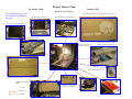
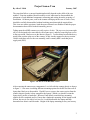
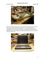
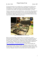
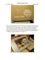
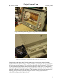
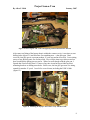
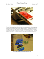
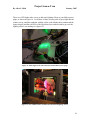
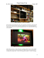
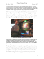
Project Scan-a-Tron
By Allen C. Haid
January, 2007
The “Scan-a-Tron” case mod project is the realization of an idea I had over a year ago.
The original concept was to build a computer into an old HP ScanJet 6100C that I bought
from a work auction for just a couple of bucks. I had the scanner taken apart within a day
of bringing it home, but soon realized that it wasn’t going to be deep enough to
accommodate modern CPU coolers and especially graphic cards or even a normal-sized
PSU. So I put the scanner back together and let it sit in my workshop, collecting dust.
Fast forward about eight months and I was now looking at an old HP Pavilion ze4145
laptop that was available to me since I had just given my wife a new replacement laptop
for her birthday. This three-year old laptop wasn’t much use for anything more than
browsing the Internet, so I figured this was my answer to the size issues of the original
Scan-a-Tron concept. I could work around the space limitations after all.
Figure 1 Like a new father, Allen is proud of Scan-a-Tron
Scan-a-Tron was scheduled to be a holiday 2006 project, meaning I would have the parts
on hand and do most of the build during the last week of December. This week has
become my annual mod week, and as long as I prepare for the work ahead of me, I can
usually get the job completed before New Year’s Eve is history - sort of a last hurrah to
the current year.
The first step in modding is to come up with a concept, and then try to visualize how it
can all come together before you make the first cut. Drawings help with this task, and I
had to diagram a few important steps along with taking some critical measurements. For
one thing, I decided that Scan-a-Tron would be mounted in my work bench shelving unit
(see figure 1). It was a tight fit, as I had only 0.5 inches total clearance on the sides.
The Build Process Diagram on the next page provides the basic layout of the mod.
1
Project Scan-a-Tron
By Allen C. Haid
January, 2007
Build Process Diagram
It’s a simple process, if you
can visualize everything at
one time!
Custom laser-etched window made by Hyperkore Computers
My donor laptop, an HP ze4145
The motherboard stays with the chassis
No need for the old laptop display
The scanner PSU is history
My donor scanner, the
HP ScanJet 6100C
Cold cathodes on both sides, with
the hardware mounted underneath
Cold cathodes inside the cavity
A USB 2.0 hub for external devices
Measuring the old scanner glass that’s being replaced
An HP USB 2.0 Cardbus
adapter
LEDs to be cut apart for the
perimeter of the window
Legend
Item removed
Item added
A 60mm fan will suffice for cooling
2
Project Scan-a-Tron
By Allen C. Haid
January, 2007
The steps that follow a concept formulation basically depend on the skills of the case
modder. First time modders should carefully review what must be disassembled, the
placement of each additional component, measuring and writing down the sequence of
installation. All donor parts, such as the scanner and laptop in the case of Scan-a-Tron,
should be carefully disassembled without breaking parts that might be required later.
This is an area where experience leads the more seasoned case modder to find the proper
documentation that will aid in the disassembly process.
Taking apart the old HP scanner was really a piece of cake. The top cover just came right
off (it was designed to be removable by the scanner user), and after removing four screws
in the top section, I had access to the interior (figure 2). I realized that I needed the heavy
metal frame section at the rear of the scanner, as this was the support for the top section.
I didn’t need those rails for the scan assembly, and I certainly didn’t need that power
supply unit (PSU).
Figure 2 The interior of the HP 6100C scanner
After removing the unnecessary components, I was left with the scanner chassis as shown
in figure 3. I was now visualizing different mounting options for the HP Pavilion ze4145
laptop that I had yet to disassemble. Would I have to remove the center section from the
scanner chassis to make it deep enough for the laptop? Which way should I orient the
laptop itself, profile or landscape? Because I had already considered my mounting
options for the completed project, I knew that a landscape mounting for the laptop would
be best, but now it was time to see how far I could disassemble the laptop and thus
determine how thin it could be made. Height of the laptop mounting was my real enemy.
3
Project Scan-a-Tron
By Allen C. Haid
January, 2007
Figure 3 The scanner chassis after removing the unnecessary components
Being a somewhat experienced case modder, I looked for documentation on the laptop. I
went to the HP website and found a service manual. This is the exact type of
documentation you need for laptop disassembly. I want to thank my friend Jim for
suggesting that I look for this type of document – it probably saved me from breaking
components when I tore the laptop apart. Speaking of the laptop, in figure 4 you can see
what I was starting with.
Figure 4 The donor laptop, an HP Pavilion ze4145 (2003 era)
4
Project Scan-a-Tron
By Allen C. Haid
January, 2007
The laptop disassembly went according to plan – meaning the steps in the HP service
documentation! I knew I wasn’t going to use the laptop display. I already had a 17”
LCD mounted to my workbench, and Scan-a-Tron would be connected to that when I
was finished. But I certainly wasn’t going to break the laptop display, or even the
keyboard. I gave them to my friend Jim for his use. You never know when you’ll need a
certain part that can’t be easily purchased, so he now has a few extra parts that I didn’t
need for this case mod project. In figure 5, you can see the laptop disassembled to just
the motherboard / chassis components. These can be easily mounted within the scanner
chassis while maintaining sufficient height clearance.
Figure 5 The HP laptop chassis, aka "the guts"
Before I go too much further, I should mention a very important step, one that I
performed early in the modding process. If there are new parts or components that will
be required, the time to order them is when you are trying to visualize the completed
project. I knew I would require a few computer parts, such as a USB 2.0 hub and a USB
2.0 Cardbus adapter, but the big item was to be a laser-etched window to replace the
scanner’s glass platen. I went with the boys at Hyperkore computers
(http://www.hyperkore.com/etching/standard.html), as I have enjoyed dealing with
Tommy and the other guys on previous orders. I submitted my custom “Big Al’s” logo
design and asked Tommy to help me with the lettering layout. Tommy came up with a
few ideas and in a few weeks I had my new custom laser-etched window (figure 6). This
is the type of thing that can make a case mod really stand out from the competition!
5
Project Scan-a-Tron
By Allen C. Haid
January, 2007
Figure 6 My custom laser-etched window from Hyperkore Computers
The new laser-etched window was sized to fit in the same mounting frame where the old
HP glass platen was previously (figure 7). The window itself had to be ground along one
edge to fit under the lip of the mounting frame, but this was no big deal with a Dremel
tool. Illumination options for the scanner cavity would need to address my lighting
options for this laser-etched window, and I decided to go with some LEDs mounted along
two edges of the window (figure 8), and some cold cathode tubes mounted underneath
the laptop chassis within the scanner cavity (figure 9).
Figure 7 Using the original mounting frame for the new laser-etched window
6
Project Scan-a-Tron
By Allen C. Haid
January, 2007
Figure 8 Mounting LEDs along opposite edges of the laser-etched window
Figure 9 Mounting 12" cold cathode tubes within the scanner cavity
Getting back to the laptop itself, I had to make sure it was up to the task of running
reliably within the scanner chassis. Cooling would be a very import concern, so I started
by first removing the heatpipe CPU cooler from the AMD mobile Athlon XP CPU (figure
10) and cleaning up the thermal material before applying a fresh coat. You might have
noticed the fan I installed (figure 9); this single fan, when combined with the CPU cooler,
would be sufficient to cool this old laptop. This statement comes from my experience in
building gaming machines and addressing the extreme cooling requirements of
videocards running at their highest levels.
7
Project Scan-a-Tron
By Allen C. Haid
January, 2007
Figure 10 Removing the CPU cooler and applying fresh thermal interface material
After some test fitting of the laptop chassis within the scanner cavity, it was time to start
drilling holes (figure 11) and also time for something new – a hot glue gun. I had
received a hot glue gun as a present perhaps 15 years ago and never used it. It was sitting
on top of my shelving unit, out of arms reach. Now was the time to get it down and see
how wonderful the gluing process can be. When I was all though with the glue gun, I
figured that I had saved at least 2-3 hours of my time in not having to fabricate more
mounting brackets or drilling more holes. Believe me, the hot glue gun won’t be sitting
around for another 15 years! I used it for several items, including the USB 2.0 hub
(figure 12).
Figure 11 Mounting the laptop to the scanner cavity with three bolts
8
Project Scan-a-Tron
By Allen C. Haid
January, 2007
Figure 12 Mounting a USB 2.0 hub with the hot glue gun
The final stages of the Scan-a-Tron case mod were focused on getting all the components
to work together and also to get the case lighting worked out. There are lots of ways to
add light to your cases, and I wanted to use both cold cathodes and LEDs. As it turned
out, I found a new type of lighting device (figure 13) – Molex Lights (LEDs). These are
made by Sunbeamtech, a company known for some unique items among case modders.
Figure 13 Molex Lights are inserted into Molex power plugs
9
Project Scan-a-Tron
By Allen C. Haid
January, 2007
These new LED lights make it easy to add some lighting effects to your Molex power
plugs, as shown in figure 14. I used three of these to bring a bit of green light into the
scanner cavity, and that combined with the yellow cold cathode tubes (underneath the
laptop chassis) and the red LEDs of the Hyperkore laser-etched window gave me the
lighting effect I was looking for (figure 15).
Figure 14 Molex lights work well when inserted into Molex power plugs
Figure 15 The combined effect of LEDs and cold cathode lighting devices
10
Project Scan-a-Tron
By Allen C. Haid
January, 2007
At this point, I was almost finished. Scan-a-Tron was operational, and could be used “asis”, but I needed some place to put it. My original concept was to install this assembly
into my work bench shelving unit (figure 16), and so I elected to undertake the task of
cutting out a shelf, chiseling out part of another shelf (figure 17), and then painting the
modded section (figure 18) of the shelving unit with black sheen spray paint to bring
attention to Scan-a-Tron. The cutting part was very difficult because there isn’t much
room to allow for the saw blade. I also had to stand on my work bench and squat down,
never fun if you suffer from lower back issues like I do.
Figure 16 The work bench shelving unit before modification
Figure 17 Using a hammer and chisel to notch out the cable access hole
11
Project Scan-a-Tron
By Allen C. Haid
January, 2007
Figure 18 Painting the "modded" shelving unit
Final assembly meant feeding the video, power, and other miscellaneous cables through
the access hole and into Scan-a-Tron before installing the top section and hanging the
scanner chassis onto two screws placed appropriately into 2 X 4 studs behind the storage
room insulation.
Figure 19 Scan-a-Tron mounted into the shelving unit
And so there you have it. Scan-a-Tron isn’t a gaming machine, but it is a fine machine
for browsing the Internet and downloading driver updates for my other projects while
working in my storage room. It runs well, being quiet and stable. Overall, I’m happy!
12
Project Scan-a-Tron
By Allen C. Haid
January, 2007
13