1
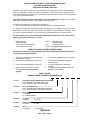
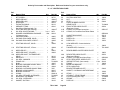
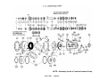
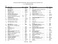
GARDNER DENVER® TUL-C-600 Rev A January, 2005 CENTRIFUGAL PUMPS 4” x 5” and 5” x 6” PARTS LIST OPERATING AND SERVICE MANUAL ECN 1024021 MAINTAIN PUMP RELIABILITY AND PERFORMANCE WITH GENUINE GARDNER DENVER PARTS AND SUPPORT SERVICES Gardner Denver® genuine pump parts are manufactured to design tolerances and are developed for optimum dependability. Design and material innovations are the result of years of experience with hundreds of different pump applications. Reliability in materials and quality assurance is incorporated in our genuine replacement parts. Your authorized Gardner Denver Sales Office offers all the backup you’ll need. The Fort Worth Manufacturing Facility maintains a large inventory of genuine parts. Gardner Denver supports your needs with these services: 1. Trained parts specialists to assist you in selecting the correct replacement parts. 2. Repair and maintenance kits designed with the necessary parts to simplify servicing your pump. Authorized service technicians are factory trained and skilled in pump maintenance and repair. They are ready to respond and assist you by providing fast, expert maintenance and repair services. For the location of your local authorized Gardner Denver distributor, refer to the yellow pages of your phone directory or contact: Gardner Denver Pump Products 4747 South 83rd East Avenue Tulsa, Oklahoma 74145 Phone: (918) 664-1151 (800) 637-8099 Fax: (918) 664-6225 Email: [email protected] INSTRUCTIONS FOR ORDERING REPAIR PARTS All orders for parts should be placed with the nearest authorized distributor and should include the following information: The name and address of your company The pump model and serial number (see nameplate on the unit.) Part number and description of the part. Part number and description of the part. Specify exactly the number of parts required (do not order by sets or groups). The name and telephone number of contact person. Your purchase order or requisition number. Complete shipping address (where the parts are to be shipped. MODEL MATRIX ORDER BY MODEL NUMBER FROM NAMEPLATE 1 COLUMN 1 - DISCHARGE OPEINIGN SIZE 4 inch – Requires 5 inch suction opening size 5 inch – Requires 6 inch suction opening size COLUMN 2 - SUCTION OPEINING SIZE 5 inch – Required with 4 inch discharge opening size 6 inch - Required with 5 inch discharge opening size COLUMN 3 - IMPELLER C – Clockwise CC – Counterclockwise COLUMN 4 - PACKING S – Square O – Oil Seal WEAR PLATES R – Rubber S – Steel SHAFT K – Key Drive S – Spline Drive COLUMN 5 - COLUMN 6 - FOREWORD TUL-C-600 Page i 2 3 4 5 6 Gardner Denver® pumps are the result of advanced engineering and skilled manufacturing. To be assured of receiving maximum service from this pump the owner must exercise care in its operation and maintenance. This book is written to give the operator and maintenance personnel essential information for day-to-day operation, maintenance and adjustment. Careful adherence to these instructions will result in economical operation and minimal downtime. Gardner Denver Design Features Give Long Life & Easy Maintenance. A light weight, compact, 4”x5” Pump and a medium weight 5”x6” Pump are extremely rugged and require minimal mounting space. A heavy steel frame and mounting bracket for horizontal or vertical positioning. Every frame is predrilled to accept a direct drive SAE hydraulic motor, in conjunction with an internal splined shaft to eliminate down time due to misalignment. A key driven shaft is also available. Segmented construction allows the customer to purchase only those parts necessary for repair. Sacrificial front and rear wear plates are provided with every new pump. Rubber coated palates are normally provided, although steel plates are available for exotic mediums such as Zylene and Toluene. Change of rotation may be easily accomplished by simply removing, turning, and repositioning the volute and changing the impeller to match the desired direction of rotation. The open impellers allow the free movement of large particles and extremely heavy, abrasive laden slurries. Available in either a clockwise or counterclockwise rotation, the impeller is secured to the shaft by a superior designed locking system. We offer two packing choices. Solid lip seals provide efficient service and with a minimal amount of attention. Split compression type packing is available for more severe service conditions and can easily be replaced without dismantling the pump. Bearing are double row inboard for radial thrusts, and a single row outboard for axial thrusts. DANGER Danger is used to indicate the presence of a hazard, which will cause severe personal injury, death or substantial property damage if the warning is ignored. WARNING Warning is used to indicate the presence of a hazard, which can cause severe personal injury, death or substantial property damage if the warning is ignored. CAUTION Caution is used to indicate the presence of a hazard, which will or can minor personal injury or property damage if the warning is ignored. NOTICE Notice is used to notify people of installation, operation or maintenance information which is important but not hazard related. TUL-C-600 Page ii cause SAFETY PRECAUTIONS Safety is everybody’s business and is based on your use of good common sense. All situations or circumstances cannot always be predicted and covered by established rules. Therefore, use your past experience, watch out for safety hazards and be cautious. Some general safety precautions are given below: DANGER Failure to observe these notices could result in injury to or death of personnel. Keep fingers and clothing away from unit inlet and discharge ports, revolving belts, sheaves, drive couplings, etc. Do not use the air discharge from this unit for breathing – not suitable for human consumption. Do not loosen or remove the oil filler plug, drain plugs, covers or break any connections, etc., in the unit or oil system until the unit is shut down and all pressure has been relieved. Electric shock can and may be fatal. The unit must be grounded in accordance with the National Electrical Code. Open main disconnect switch, tag and lockout before working on the control. Disconnect the unit from its power source, tag and lockout before working on the unit – the machine may be automatically controlled and may start at any time. WARNING Failure to observe these notices could result in damage to equipment. Stop the unit if any repairs or adjustments on or around the unit are required. Do not exceed the rated maximum speed shown on the nameplate. Do not operate unit if safety devises are not operating properly. Check periodically. Never bypass safety devices. TABLE OF CONTENTS TUL-C-600 Page iii Maintain Pump Reliability and Performance with Genuine Gardner Denver Parts and Support Services ............................................................................................................... i Instructions For Ordering Repair Parts...................................................................................... i Model Matrix .............................................................................................................................. ii Forward...................................................................................................................................... iv Safety Precautions .................................................................................................................... v Section 1, Pump Danger Notices .............................................................................................. 1 Section 2, Centrifugal Pump Fundamentals.............................................................................. 5 Section 3, Maintenance ............................................................................................................. 18 Section 4, Parts List................................................................................................................... 37 TUL-C-600 Page iv INDEX Centrifugal Pump-4”x5” Exloded View........................................ 37 Parts Listing … ..................................... 38 Centrifugal Pump-5”x6” Exploded View ….. ............................... 39 Parts Listing.......................................... 40 Centrifugal Pump Fundamentals Section 2................................................. 5 Covers and Guards Danger Notice Maintain Pump Reliability and Performance With Genuine Gardner Denver Parts and Support Services ................................I Maintenance Section 3 ..........................................................18 Mechanical Oil Seals, Packing Pump ..............12 Model Matrix........................................................I Moving and Lifting Equipment Danger Notice ....................................................2 kk DANGER NOTICES Covers and Guards ................................ 2 Equipment Moving and Lifting ................ 2 Flammable, Hot, Cold or Corrosive Fluid Pumping ................................ 4 Pressurized Pump Systems……………..3 Equipment Moving and Lifting Danger Notice......................................... 2 Figure 2-1 – Identical Pump Handling Liquids of Different Specific Gravities ................................................. 5 Figure 2-10 – Hydraulic Motor Mounting Specifications – 5”x6” ........................... 17 Figure 2-11 – Performance Curve – 5”x6”.... 17 Figure 2-2 – Static Head Pump Locations………………………………….6 Figure 2-3 – Net Positive Suction Head (NPSH) and Cavitation ........................... 8 Figure 2-4 – Parallel and Series Operation .... 9 Figure 2-5 – Standard Torque Chart ............ 13 Figure 2-6 – Installation Dimensions – 4”x5”...................................................... 14 Figure 2-7 – Hydraulic Motor Mounting Specifications – 4”x5” ........................... 15 Figure 2-8 – Performance Curve – 4”x5”...... 15 Figure 2-9 – Installation Dimensions – 5”x6”...................................................... 16 Flammable, Hot, Cold or Corrosive Fluid Pumping Danger Notice ......................... 4 Forward .......................................................... ii Friction Head .................................................. 6 Lifting and Moving Equipment Danger Notice......................................... 2 TUL-C-600 Net Positive Suction Head (NPSH) ....................7 Packing Pump with Mechanical Oil Seals........12 Parallel and Series Operation ...........................9 Parts List – Section 4 .......................................37 Pressure Head ...................................................7 Pressurized Pump Systems Danger Notice ............................................3 Pump Danger Notices Section 1 ....................................................1 Removal of Rotating Assembly Only................23 Repair Parts – Ordering Instructions...................i Rotating Assembly Only, Removal...................23 Safety Precautions ............................................. ii Square Braided Packing ..................................11 Packing and Adjustment ..........................11 Standard Torque Chart ....................................13 Static Discharge Head .......................................6 Static Suction Head............................................6 Stuffing Box Packed with Mechanical Oil Seal.....................................................29 Suction Head......................................................6 Suction Lift..........................................................6 Technical Data – 4”x5” ...............................14, 15 Technical Data – 5”x6” ...............................16, 17 Total Dynamic Discharge Head .........................7 Total Dynamic Suction Head..............................7 Total Dynamic Suction Lift .................................7 Total Head..........................................................7 Trouble Shooting ..............................................10 Velocity head......................................................6 Page v SECTION 1 DANGER NOTICES DANGER Read and understand the following DANGER NOTICES before moving or operating the pump or any pump package unit equipment. Pumps are machines capable of producing high fluid pressures and flow rates and are designed to be used with proper care and caution by trained, experienced operators. TO AVOID PERSONAL INJURY, DEATH AND/OR EQUIPMENT DAMAGE, READ AND THOROUGHLY UNDERSTAND THE FOLLOWING DANGER NOTICES PLUS THE ENTIRE OPERATING AND SERVICE MANUAL BEFORE ATTEMPTING TO MOVE OR OPERATE THE PUMP. Contact a Gardner Denver service representative, if you are unable to comply with any of the danger notices or procedures described in these documents. Closely examine the pump performance data upon pump delivery to become thoroughly familiar with the operating limits for this pump model. The pump must never be operated at speeds, pressures or horsepower exceeding the maximum values or at speeds below the minimum. Failure to observe the operating limits could result in personal injury, death, and/or equipment damage and will void the warranty. Alterations to the pump, or application of the pump outside the limits, must not be made without Gardner Denver written approval, together with a new set of performance data, as dangerous operating conditions could result. THE DANGER NOTICE AND DATA PLATED PROVIDED ON THE EQUIPEMNT MUST NOT BE REMOVED, PAINTED OVER, HIDDEN OR DEFACED. They must be replaced if they become damaged or unreadable. Provisions should be made to have the following written danger notices plus the pump operating and service manual readily available to operators and maintenance personnel. In addition, copies of all pump system accessory component (e.g. hydraulic motor, engine, and electric motor, etc.) Read and follow all the precautions and instructions contained in these manuals. If any of these documents are lost or become illegible they must be replaced immediately. The danger notices plus the operating and service manuals should be reread periodically by both operators and maintenance personnel to refresh their memories in safe procedures and practices. Keep in mind that full operator attention and alertness are required when operating high pressure pumping equipment. Operators should not begin or continue operations when tired, distracted or under the influence of alcohol or any type of prescription or nonprescription drugs. The timely replacement of expendable parts and any other worn or damaged parts can prevent equipment damage and possible injury. The original parts used in Gardner Denver pumps are designed and tested to exacting standards to provide high quality performance and durability. Your best insurance in maintaining these characteristics is to use genuine Gardner Denver replacement parts. A broad range of danger notices are covered on these pages, however, they cannot substitute for training, experience and common sense in the safe operation of high pressure pumping equipment. TUL-C-600 Page 1 COVERS AND GURARDS DANGER All moving parts on the entire pump package, including but not limited to engine or motors, drive shafts, belts, chains, pulleys, gears, etc., must be equipped with guards or covers, which must also be securely fastened in proper position at all times when the equipment is operating. Covers and guards are intend to not only protect against personal injury or death, but to also protect the equipment from damage from foreign objects. EQUIPMENT MOVING AND LIFTING DANGER Heavy equipment including pumps, pump package units and components should only be moved or lifted by trained, experienced operators, who are physically and mentally prepared to devote full attention and alertness to the moving and lifting operations. An operator should be fully aware of the use, capabilities and condition of both the equipment being moved, and the equipment being used to move it. DANGER Failure to follow safe and proper pump, pump package or component lifting or moving procedures can lead to personal injury, death and/or equipment damage from shifting, falling or other unexpected or uncontrolled equipment movements. Make sure the hoist, lift truck, ropes, slings, spreader, or other lifting equipment you are using is in good condition and has a rated lifting capacity equal to or greater than the weight being lifted. Lifting devices must be checked frequently for condition and continued conformance to rated load capacity. They should then be tagged with the inspected capacity together with the date of inspection. Fully assembled pumps and pump package units are heavy and should only be moved using the specified lifting lugs or attachments. Many individual components have lifting eyes or lugs which must not be used to lift assemblies, as they are designed to bear the weight of the component only. Before lifting the individual component check to insure the lifting attachment is firmly secured to the component with undamaged, properly torqued fasteners, sound welds, or other secure attachments. Examine the lifting eyes, lugs, slots, holes or other projections to insure they are not cracked, otherwise damaged or badly worn. The repair of existing or addition of new welded lifting eyes, lugs or other projections should only be performed by experienced, qualified welders. Package units should be lifted with spreaders connected to the lifting attachments normally built into the package unit support skid. Packages too large to lift fully assembled should be separated into small loads. For these smaller loads the lifting devices should be fastened to the lifting attachments normally built into the individual motor, engine, pump or transmission/torque converter, or their separate support skids. When lifting subassembled components, for example a suction stabilizer attached to suction piping or a discharge pulsation dampener attached to a strainer cross and piping, use special lifting slings designed to safely support the combined weight of the components. If a crane or hoist is being used to lift large components or assemblies, one or more persons should assist the operator from the ground with guide lines attached to the equipment being moved to properly position it and prevent uncontrolled movement. TUL-C-600 Page 2 When you start to lift a pump, package unit, subassemblies or individual components, and you observe the equipment is tilting or appears unbalanced, lower the equipment and adjust the lifting device to eliminate these improper lifting conditions before proceeding to move the equipment. It is poor practice and dangerous to allow the equipment to pass over or close to your body or limbs. Be prepared to move quickly out of danger if equipment starts to fall, slip or move unexpectedly toward you. PRESSURIZED PUMP SYSTEMS DANGER Fluids under high pressure can possess sufficient energy to cause personal injury, death and/or equipment damage either through direct contact with escaping fluid streams or by contact with loose objects the pressurized fluid propels. Operating a pump against a blocked or restricted discharge line can produce excessive pressures in the entire discharge system, which can damage or burst discharge system components. Continually monitor suction and discharge hose assemblies when the pump is operating for leakage, kinking, abrasion, corrosion or any other signs of wear or damage. Worn or damaged hose assemblies should be replaced immediately. At least every six months examine hose assemblies internally for cut or blulged tube, obstructions and cleanliness. For segment style fittings, be sure that the hose butts up against the nipple shoulder, the band and retaining ring are properly set and tight and the segments are properly spaced. Check for proper gap between nut and socket or hex and socket. Nuts should swivel freely. Check the layline of the hose to be sure that the assembly is not twisted. Cap the ends of the hose with plastic covers to keep them clean until they are tested or reinstalled on the pump unit. Following this visual examination, the hose assembly should be hydro statically tested on the test stands having adequate guards to protect the operator, per the hose manufacturer’s proof test procedure. Component inspections should be performed more frequently than every six months if corrosive, flammable or hot (over 110F) fluids are being pumped. Proper packing selection is important for safe pump operation. Contact a Gardner Denver service representative for assistance in selecting the proper packing before beginning operation. DANGER Don not attempt to service, repair, adjust the packing or otherwise work on the pump while the unit is operating. Shut off the pump drive motor or engine and relieve the fluid pressure in the pump suction and discharge systems before any work or investigation is performed on the pump or pump systems. Whenever the pump is operating, continually monitor the entire suction, discharge and pump lubricating systems for leaks. Thoroughly investigate the cause for leakage and do not operate the pump until the cause of the leak has been corrected. Replace any parts which are found to be damaged or defective. When a gasketed joint is disassembled for any reason, discard the used gasket and replace it with a new genuine Gardner Denver gasket before reassembling the joint. TUL-C-600 Page 3 In summary, high pressure fluid streams can possess sufficient energy to cause personal injury, death and/or equipment damage. These results can occur either through direct contact with the fluid stream or by contact with loose objects the fluid stream has propelled, if the pump system is improperly used, or if the fluid is misdirected or allowed to escape from defective or improperly maintained equipment. FLAMMABLE, HOT, COLD OR CORROSIVE FLUID PUMPING DANGER Extreme caution must be exercised by trained and experienced operators when flammable, hot cold or corrosive fluids are being pumped, in order to avoid personal injury, death and/or equipment damage due to explosion, fire, burn, extreme cold or chemical attack Never operate a pump which is pumping hydrocarbons or other flammable, hot, cold, or corrosive fluids when any part of the pump, suction system or discharge system is leaking. Stop the pump immediately if any leakage, other than a few drops per minute of packing weepage, is observed. Keep all flame, sparks, or hot objects away from any part of the pump, suctions system or discharge system. Shield the pump, suction system an discharge system to prevent any flammable, hot, cold or corrosive fluid leakage from dripping or spraying on any components, flame sparks, hot objects or people. Inspect the packing, gaskets and seals for fluid leakage frequently and replace worn or leaking parts. Selection of the proper gaskets, seals and packing is even more critical when flammable, hot, cold or corrosive fluids are being pumped than when other, inherently less dangerous fluids are used. Contact a Gardner Denver service representative for assistance in selecting the proper gaskets, seals and packing before beginning operation. Since some packing seepage is inevitable, a catch pan is required and must be connected to a drain line which conducts container located in a protected area. The entire drain system and container must be constructed of materials resistant to attack from the pumped fluid or from explosion or fire of the pumped fluid. Before beginning pumping operations or starting the pump power source (whether an engine or electric or electric motor) check the atmosphere all around the pumping site for the presence of flammable or explosive vapors are detected. Hot surfaces, sparks, electric current or engine exhaust could ignite flammable or explosive vapors. Each engine used as a power source on pumping units where flammable or explosive vapors could form should be equipped with an air inlet shut-off. If flammable or explosive vapors are present in the pumping site atmosphere, an engine could continue to run on these vapors, even after the engine fuel line is shut-off, if an air inlet shut-off is not used. In addition, on pumping units used where flammable or explosive vapors could from, all electric motors used as power sources must be of explosion proof construction and all electrical components and wiring must meet the current National Electrical Code for explosive atmospheres. For these smaller loads the lifting devices should be fastened to the lifting attachments normally built into the individual motor, engine, pump or transmission / torque converter, or their separate support skids. These precautions must be taken to avoid possible personal injury, death and/or equipment damage from, fire or burns. SECTION 2 TUL-C-600 Page 4 CENTRIFUGAL PUMP FUNDAMENTALS The pressure at any point in a liquid can be thought of as being caused by a vertical column of liquid which, due to it’s weight, exerts a pressure directly related to the height of the column which is called the “static head” and expressed in terms of liquid feet. The static head corresponding to any specific pressure is dependent upon the weight of the liquid according to the following formula: Pressure in PSI x 2.31 Head in Feet = Specific Gravity A centrifugal pump imparts velocity to a liquid, this velocity energy is transformed into pressure energy as the liquid leaves the pump. Therefore, the head developed is approximately equal to the velocity energy at the periphery of the impeller. This relationship can be shown by the following formula: H = V2 2g Where H = Total Head Developed in Feed V = Velocity At Periphery of Impeller in Feet Per Second G = 52.2 ft/sec2 We can predict the approximate head of any centrifugal pump by calculating the peripheral velocity of the impeller and substituting the above formula. The following formula may be used to calculate peripheral velocity: RPM x D V = 229 Where D = Impeller diameter in inches This demonstrates why we must always think in terms of feet of liquid rather than pressure when working with centrifugal pumps. A given impeller diameter and speed will raise a liquid to a certain height regardless of the weight of the liquid as shown in FIGURE 2-1. Figure 2-1 – Identical Pump Handling Liquids of Different Specific Gravities Light Crude, Specific Gravity = 0.60 Discharge = 100’x0.60 = 26 PSI Pressure 2.31 Water, Specific Gravity – 1.0 13# Cement, Specific Gravity = 1.5 Discharge = 100’x1.0 = 43 PSI Discharge = 100’x1.5 = 65PSI Pressure 2.31 Pressure 2.31 All of the forms of energy involved in a liquid flow system can be expressed in terms of feet of liquid. The total of these various heads determines the total system head or the work which a pump must perform in the system. The various forms of head are defined as follows. Refer to FIGURE 2-2. TUL-C-600 Page 5 SUCTION LIFT exists when the source of supply is below the center line of the pump. Thus the STATIC SUCTION LIFT is the vertical distance in feet from the centerline of the pump to the free level of the liquid to be pumped. STATIC HEAD exists when the source of supply is above the centerline of the pump. Thus the STATIC SUCTION HEAD is the vertical distance in feet from the centerline of the puMp to the free level of the liquid to be pumped. STATIC DISCHARGE HEAD is the vertical distance in feet between the pump centerline and the point of free discharge or the surface of the discharge liquid. FRICTION HEAD (hf) is the head required to overcome the resistance to flow in the pipe and fitting. It is dependent upon the size and type of pipe, flow rate, and nature of the liquid. VELOCITY HEAD (hv) is the energy of a liquid as a result of its motion at some velocity V. It is the equivalent head in feet through which the water would have to fall to acquire he same velocity, or in other words, the head necessary to accelerate the water. Velocity head can be calculated from the following formula. Hv = Where g= V= V2 2g 32.2 ft./Sec. liquid velocity in feet per second The velocity head is usually insignificant and can be ignored in most high head systems. However, it can be a large factory and must be considered in low head systems. Suction Lift Showing Static Heads in a Pumping System Were the Pump is Located Above the Suction Tank (Static Suction Head) Suction Head Showing Static Heads in a Pumping System Where the Pump is Located Below the Suction Tank (Static Suction Head) Figure 2-2 – Static Head Pump Locations PRESSURE HEAD must be considered when a pumping system either begins or terminates in a tank which is under some pressure other that atmospheric. The pressure in such a tank must first be converted to feet of liquid. A vacuum in the suction take or a positive pressure in the TUL-C-600 Page 6 discharge tank must be added to the system head. Whereas a positive pressure in the suction tank or vacuum in the discharge tank would be subtracted. The following formula is for converting inches of mercury vacuum into feet of liquid. Vacuum, Ft of liquid = Vacuum, in Hg x 1.13 Specific Gravity The above forms of head, namely static, friction, velocity, and pressure, are combined to make up the total system head at any particular flow rate. Following are definitions of theses combined or “Dynamic” head terms as they apply to the pump. TOTAL DYNAMIC SUCTION LIFT (hs) is the static suction lift plus the velocity head at the pump suction flange plus the total friction head in the suction line. The total dynamic suction lift, as determined on pump test, is the reading of a gage on the suction flange, converted to feet of liquid and corrected to the pump centerline, minus the velocity head at the point gage attachment. TOTAL DYNAMIC SUCTION HEAD (hs) is the static suction head minus the velocity head at the pump discharge flange plus the total friction head in the discharge line. The total dynamic discharge head, as determined on pump test, is the reading of a gage at the discharge flange, converted to feet of liquid and corrected to the pump centerline, plus the velocity head at the point of gage attachment. TOTAL DYNAMIC DISCHARGE HEAD (hd) is the static discharge head plus the velocity head at the pump discharge flange plus the total friction head in the discharge line. The total dynamic discharge head, as determined on pump test, is the reading of a gage at the discharge flange, converted to feet of liquid and corrected to the pump centerline, plus the velocity head at the point of gage attachment. TOTAL HEAD (H) pr TOTAL DYNAMIC HEAD (TDH) is the total dynamic discharge head minus the total dynamic suction head or plus the total dynamic suction lift. NET POSITIVE SUCTIO HEAD (NPSH) NPSH may be defined as the total suction head in feet absolute, determined at the suction nozzle and corrected to datum, less the vapor pressure of the liquid in feet absolute. Simply stated, is an analysis of energy conditions on the suction side of a pump which will determine if a liquid will vaporize at the lowest pressure point in a pump. The majority of centrifugal pump problems are a direct result of less than required NPSH. We will attempt to list several things that can be done on the average hook up to improve or eliminated these problems. While you will not be expected to calculate available NPSH it is important to understand this characteristic of centrifugal pumps so as to avoid problems when laying and hooking up suction hose and lines. Although most factors of available NPSH are controllable, friction loss is usually easier than th other. Keep suction lines as short and straight as possible. The maximum volume for a 4” suction hose is 8 BPM under ideal conditions. This can change with long lines, high lift and many other conditions which would indicate a lower rate. The higher the flow rate, the higher the friction loss which can result in air or vapor separation. This is always complicated further by elbows, tees and other sharp turns. Especially those located near the pump suction where they can set up uneven flow patterns or vapor separation which causes uneven filling of the impeller vanes. This can affect the hydraulic balance of the impeller, leading to possible cavitation, excessive shaft deflection breakage and premature bearing and impeller retaining bolt failures. One of the most frequently encountered problems when there is insufficient NPSH available is cavitation. This term is used to describe the phenomenon which occurs in pumps when the pressure of the liquid being pumped is reduced to a value equal to or below its vapor pressure TUL-C-600 Page 7 and small bubbles move along the impeller blades to higher pressure area, where they rapidly collapse and implode. This is usually heard as a growling or rumbling sound, much like the noise you would hear if you were pumping gravel. The forces are sometimes high enough to cause small fatigue failures on the impeller vane surfaces. This of course is progressive under long period of this condition and the pitting and fatigue failure are refereed to as “cavitation erosion” which can sometimes be severe enough to cause vibration, shaft and bearing failure. The only way to prevent the undesirable effect of cavitation is to insure that the NPSH available to the system is greater than the NPSH required by the pump. Refer to figure 2-3 PB vp P LS LH h1 = = = = = = Barometric pressure, in feet absolute. Vapor pressure of the liquid at maximum pumping temperature in feet absolute. Pressure on surface of liquid in closed suction tank, in feet absolute. Maximum static suction lift in feet. Minimum static suction head in feet. Friction loss in feet in suction pipe at required capacity. Figure 2-3 - Net Positive Suction Head (NPSH) and Cavitation PARALLEL & SERIES OPERATIONS TUL-C-600 Page 8 Sometimes it is necessary to operate two or more pumps in conjunction with one another. The operation will be either parallel or series depending on the arrangement. Refer to FIGURE 2-4. In a parallel operation, the discharge head is equal to that of one pump, and the volume is equal to the total of the two. In this case, care should be exercised with the suction manifold to insure that one pump does not starve. Also the discharge capabilities of each pump should be fairly close to avoid one pump moving fluid back through the second pump. The results of a series operation is the opposite of parallel systems. The volume is limited to the capacity of one pump but the head is equal to the sum of the two. This occurs because performance curves denote the differential head across the pump so the second pump will add its head to the head supplied to its suctin by the first pump. If this is attewmpte4d, it is imperative to know the maximum working case pressure of the pump to avoid bursting the second pump. In oil field service, this type of hook up is seldom if ever used, never with slurry, In industrial service, it is done on a limited basis pumping fluids. Due to the high incidence of seal failure in the second pump, this type if operation should be discouraged. EXAMPLE Two pumps, each having the capacity of 20 BPM @ 100 ft. of head, are to be operated together. The output for parallel and series operations is as follows: Parallel Operations: Volume = 20 BPM + 20 BPM = 40 BPM Head = 100 ft. Series Operation: Volume = Head = 20 BPM 100 + 100 = 200 ft. Although the theoretical head for series operation is 200 ft., the actual head will be somewhat lower. This is due to the friction loss in the manifold between pumps and will vary with volumes and manifold. TROUBLE SHOOTING SHART Complaint 1. Pump will not “pick up prime”. TUL-C-600 Page 9 a. Pump too high above source of liquid. b. Seals or packing taking in air around shaft. c. Too much head space between impeller and front wear plate. d. Pump speed too slow. e. Restriction or blockage in suction. f. Worn parts, impeller, wear plates or volute. g. Impeller loose on shaft or key broken. 2. Low discharge pressure. a. Worn parts, impeller, wear plates, or volute. b. Restriction in suction. c. Pump speed too slow. d. Too much head space between impeller and front wear plate. 3. Pump noisy or vabrates. a. Cavitation b. Worn bearings. c. Out of balance. d. Loose mounting bolts. e. Misaligned coupling. f. Speed too high. g. Broke impeller vane. 4. Pump leaks around bolts at volute. a. Wear plates not sealing at volute. 5. Slurry pumps Slurry pumps will sometimes hold a normal discharge pressure and on hydraulically driven pumps the hydraulic pressure will be normal when pumping water. As the slurry weight increases the pumps and hydraulic pressures become erratic, the pump suddenly stops pumping and hydraulic pressure will usually drop to 25% of normal. The condition can almost always be traced to defective shaft seals in pump or seals that have been installed improperly with all the seal lips facing impeller. Next to the last seal in any mechanical seal arrangement must always face opposite the impeller to prevent air pick up around shaft. To determine if the problem are the seals or a hydraulic problem, stall the pump (hydraulically driven unit only) and observe hydraulic pressure. If it is normal (usually 2600-2800 psi), the problem are the seals in the pump and not the hydraulic system. SQUARE BRAIDED PACKING This section covering square braided packing is being included as an alternate method of packing as most pumps are equipped with mechanical seals at time of construction. One TUL-C-600 Page 10 advantage of the square braided packing is that in an emergency, extra packing can usually be added very quickly. If a mechanical seal fails, it can sometimes be a major operation to replace these seals. The disadvantage of square braided packing is that it requires more maintenance, and it can burn out in minutes if not properly adjusted For cooling and lubrication, it should leak a small amount except as noted in number 7, page 8. Tests show that the life is approximately 400% less than for mechanical seals. Asbestos packing is no longer available. Tests indicate the following listed packing may be substituted with little or no problems so long as proper adjustment is maintained. Garlock #98 Temperature to: 650 F (345 C) Parker #5700 800 F (426 C) Teflon from most manufacturers 550 F (288 C) None of the three packing materials listed above need external lubrication except during installation and break-in. PACKING AND ADJUSTMENT PROCEDURE FOR SQUARE BRAIDED PACKING 1. Remove old packing from the stuffing box. 2. Inspect shaft and stuffing box for cleanliness and wear. Replace worn parts and clean stuffing box as required. 3. Cut rings to proper length if they have not been provided pre-cut, by use of spare shaft or packing cutter. Always cut ends on a bias to prevent leakage. 4. Lubricate I.D. of each ring prior to installation with some type of break-in lubricant such as chassis lube. Lubricate the I.D. only. 5. Install each ring individually and seat firmly to the bottom of stuffing box or previously installed ring. Rotate the joint or open end of each successive ring 90 apart, i.e., 12:00, 3:00, 6:00, 9:00 o’clock when using four rings or more. This is done to minimize leakage paths through the body of packing set. 6. After the last ring has been installed, tighten the packing follower only hand tight. 7. Open suction and discharge valves, start pump and allow packing to leak for 10-15 minutes without adjusting the packing follower. During this period pump should be run at approximately ½ speed. This procedure is very important as it allows the packing to take a “set” and conform to the contour of the shaft and stuffing box. 8. After run in period has been completed, start adjusting packing follower in very minor increments allowing 5-10 minutes between adjustments until leakage has reached a very low level. When pumping water it is always advisable to let packing leak a small amount. This provides cooling and lubrication. In preparing for pumping latex or other fluids where no leakage can be tolerated, the same procedure should be followed and packing should be tightened slowly to just the point where no leakage occurs. CAUTION TUL-C-600 Page 11 The previously listed packing is designed to run without lubrication except for break-in period. It should never be tightened any more than is necessary to stop excessive leakage as this increases temperature and accelerated shaft wear. CAUTION A lantern gland is installed in square braided packing which requires lubrication. Some types of packing require NO lubrication (except as noted in Number 4, this page). If nonlubricated packing is used, the lantern gland should be removed and replaced with ne extra packing ring. Refer to Figures on page 29. PACKING PUMP WITH MECHANICAL OIL SEALS 1. Remove old packing or oil seals from stuffing box. 2. Inspect stuffing box for cleanliness and wear. Clean as required. 3. Install first two oil seals with lips facing the impeller. 4. The next seal is installed with the lip facing rear of pump and away from impeller. This seal prevents air pick up around shaft. 5. The last seal is installed with lip facing impeller as first seals were installed. Some pumps require a small spacer behind th elast seal. If a print of pump is not available, it may be assumed that a spacer will be needed if last seal is not flush with rear of stuffing box. 6. Install packing fland or suffing box nut and tighten at this time. 7. Make sure that the oiler is operating properly. 8. Start pump and circulate water for five minutes, check for leaks andmake sure oiler cycles whild pump is running. 9. No further adjsutments will be necessary for the life of the seals. STANDARD TORQUE CHART TUL-C-600 Page 12 GENERAL TIGHTENING TORQUE FOR BOLTS, NUTS AND TAPERLOCK STUDS The following charts give the standard torque values for bolts, nuts and studs of SAE Grade 5 or better quality. Exceptions are given in other sections of the Service Manual where needed. Use these torques for bolts and nuts with standard threads (conversions are approximate). THREAD DIAMETER STANDARD TORQUE iches millimeters lb. ft. Nm 1/4 12 + 4 6.35 9+3 5/16 18 + 5 25 + 7 7.94 32 + 5 45 + 7 3/8 9.53 50 + 10 70 + 15 7/16 11.11 75 + 10 100 + 15 1/2 12.70 110 + 15 150 + 20 9/16 14.29 150 + 20 200 + 25 5/8 15.88 265 + 35 360 + 50 3/4 19.05 420 + 60 570 + 80 7/8 22.23 640 + 80 875 + 100 1 25.40 800 + 100 1000 + 150 1-1/8 28.58 1000 + 120 1350 + 175 1-1/4 31.75 1200 + 150 1600 + 200 1-3/8 34.93 1500 + 200 2000 + 275 1-1/2 38.10 TUL-C-600 Page 13 4” x 5” – TECHNICAL DATA Note: Assembly shown is Counterclockwise Pump TUL-C-600 Page 14 4” X 5” TECHNICAL DATA TUL-C-600 Page 15 5” x 6” TECHNICAL DATA Note: Assembly shown is Counterclockwise Pump TUL-C-600 Page 16 5” x 6” TECHNICAL DATA TUL-C-600 Page 17 SECTION 3 MAINTENANCE The 4” x 5” and the 5” x 6” pumps are similar except for the physical size and the packing arrangement in the stuffing box. Therefore only one set of photos and instructions will be used for maintenance and overhaul of these two pumps. If the entire pump assembly as shown in FIGURE 3-1 is removed from the pumping unit, start disassembly by removing the entire row of nuts around the suction adaptor. TUL-C-600 Page 18 After the nuts are removed, pull the suction adaptor and front wear plate out as an assembly. See FIGURE 3-3. FIGURE 3-4 shows the suction adaptor and front wear plate removed from the volute. TUL-C-600 Page 19 Remove the two nuts as shown in FIGURE 3-5 to separate the front wear plate from the suction adaptor. After the two nuts are removed, separate the front wear plate from the suction adaptor. See FIGURE 3-6. Remove the setscrew, impller retaining bolt and lock as shown in FIGURE 3-7. Remove the impeller assembly. See FIGURE 3-8. TUL-C-600 Page 20 Remove two nuts from the rear of the wear plate, pry evenly on the heads of the wear plate studs. This will ppush the wear plate out of the housing which will give access to the stuffing ox. Remove the lubricator fitting from the stuffing box and then slide the box off over the shaft and out of the pump housing. See FIGURE 3-9. TUL-C-600 Page 21 In the volute and suction adaptor are to be left on the pumping unit and only the rotating assembly is to be removed for service, remove the complete row of bolts as indicated in FIGURE 3-10. Before removing the rotating assembly, put indexing marks on the pump frame and volute with paint or center punch so that the parts can be returned to the original position when the pump is assembled. See FIGURE 3-11. TUL-C-600 Page 22 REMOVAL OF ROTATING ASSEMBLY ONLY start disassmbly here. If only rotating assembly will be removed, Remove pump frame bolts, oiler line, base bolts and motor retaining bolts as shown in FIGURE 3-12. On units with extended shaft and mechanical drive, remove couplings or U joints at this time. If the pump is driven by hydraulic motor, remove the bolts that secure the motor to the pump frame and pull the motor out of the splines. Remove the oiler line to the stuffing box. Remove the base plate bolts. Remove the row of bolts that secures the pump frame to the volute. Pull the rotating assembly out of the volute and start disassembly as indicated on page 24. TUL-C-600 Page 23 Remove the set screw, bolt and lock assembly from the impeller and shaft. See FIGURE 3-13. The impleller may now be removed with two heavy screwdrivers on a thin pry bar. See FIGURE 3-14. TUL-C-600 Page 24 Remove the two nuts from the rear of the wear plate and separate the plate from the from. See FIGURE 3-15. Remove the lubricator fitting from the stuffing box as shown in FIGURE 3-16. TUL-C-600 Page 25 Remove the stuffing box from the frame as shown in FIGURE 3-17. Remove the four bolts and nuts from the front bearing retainer bars. See FIGURE 3-18. Use a pipe wrench to remove the cap from the locking assembly. Remove the lock and spring. See FIGURE 3-19. TUL-C-600 Page 26 Pull the shaft and bearing assembly from the housing as shown in FIGURE 3-20. When the shaft and bearing assebly is removed, this will allow the bearing shims to fall free. Save these shims as they will be needed during reassembly to get he proper head spaceon the impeller. See FIGURE 3-21. If the bearing are to be replace, pry the locking washer tang out of the slot in the bearing retainer nut as shown in FIGURE 3-22. TUL-C-600 Page 27 The nut may now be removed with a blunt punch or chisel. See FIGURE 3-23. After the nut and lock are remove, the bearings and spacer may be pressed off the rear of the shaft. Inspect for wear or damage as shown in FIGURE 3-24. If the shaft is damaged, rough or has grooves worn more than .010” (.254 mm) deep in the area shown, the shaft should be replaced. TUL-C-600 Page 28 STUFFING GOX PACKED WITH MECHANICAL OIL SEALS (Qty. of 3 or 4) – See FIGURE 325 for identification and placement of parts. When non-lubricated packing is required, the lantern gland should be removed and replaced with one extra packing ring. To reassemble, insert the shaft, front bearing retainer, bearings, spacer, lock and nut as an assembly, into the pump frame. Replace the shims that were removed during disassembly under the front bearing snap ring and hold in place with the front bearing retainer. See FIGURE 3-26. TUL-C-600 Page 29 FIGURE 3-27 shows the shaft, bearings and bearing cap in place. Install the stuffing box and align the lubricating hole with grease fittings in the pump frame as shown in FIGURE 3-28. Install bearing retainer bars and bolts as shown in FIGURE 3-29. TUL-C-600 Page 30 Reassemble the locking assembly and tighten the cap. See FIGURE 3-30. FIGURE 3-31 and FIGURE 3-32 show front and rear wear plates. TUL-C-600 Page 31 Install the plate and tighten the two (2) retaining nuts only hand tight at this time. This allows the wear plate to center when the rotating assembly is inserted into the volute. See FIGURE 3-33. Install the key, impeller, lock and cap screw at this time. Torque to values shown below. Install set screw. Refer to FIGURE 3-34. LB. FT. NM 100 + 15 4x5 75 + 10 200 + 25 5x6 150 + 20 Refer to FIGURE 3-25. If the volute and suction adaptor have been removed from the unit, assemble the front wear plate to the suction adaptor as shown above. Tighten the two retaining nuts only hand tight. This allows the wear plate to center when inserted into the volute. If only the rotating assembly has been removed, turn to page 34. Install the front wear plate and suction adaptor. Tighten all nuts that secure the adaptor to the volute. Tighten the two wear plate attaching nuts last. Refer to FIGURE 3-36. TUL-C-600 Page 32 In the volute and suctions adaptor have been removed from the unit, assemble as shown in FIGURE 3-37. If only the rotating assembly and front wear plate have been removed, firtst install the front wear plate and tighten the two attaching nuts. Then assemble as shown in FIGURE 3-37. After the pump rotating assembly is installed, tighten all the attaching nuts at this time. The remaining two (2) rear wear plate nuts must always be tightened last so that the wear plate will be centered. See FIGURE 3-38. TUL-C-600 Page 33 If the entire pump has been removed from the unit, headspace between the impeller and front wear plate can be set at this time. See FIGURE 3-39. Use a shim or s0ome flat object 1/16” thick (1.588mm), insert between the impeller and the front wear plate. Add or delete shims as shown in FIGURE 3-40 until this distance of 1/16” is maintained with the front bearing retainer in place and both retaining bars tight. If the volute and suction adaptor are on the unit, loosen the front bearing retainer cross bars and push the shaft forward until the impeller engages the front wear plate. Pull or pry the shaft and impeller back 1/16” (1.588mm), add necessary shims to maintain this distance. Install and tighten the cross bars. Check the shaft for free rotation at this time. TUL-C-600 Page 34 FIGURE 3-41 shows the front view of the steel wear plates and O-rings for the 4” x 5” and 5” x 6” pumps. FIGURE 3-42 shows the front view of the steel wear plates and O-rings for the 4” x 5” and 5” x 6” pumps. TUL-C-600 Page 35 FIGURE 3-43 shows additional parts needed for extended shaft models of the 4 x 5 and 5 x 6 pumps. TUL-C-600 Page 36 Note: Assembly Shown is Counterclockwise Pump SECTION 4 PARTS LIST TUL-C-600 Page 37 Order by Part number and Description. Reference Number for your convenience only. 4” x 5” CENTRIFUGAL PUMP Ref. No. 1 2 3 4 5 6 7 7A 8 9A Name of Part Qty. Part No. 1 1 1 1 1 1 28775 19846-T 19843-T 26019 20123 45010 1 3 or 4 1 Set 19842-T 6679 26018 9 10 10A SET SCREW ............................................. IMPELLER BOLT....................................... IMPELLER LOCK ...................................... SNAP RING ............................................... THROAT BUSHING................................... GREASE FITTING..................................... Not Offered (Replaced with 7A) STUFFING BOX (Split Packing)................ OIL SEAL SOLID PACKING...................... SQUARE COMPRESSION PACKAGE ..... (5 pieces per set) LANTERN GLAND..................................... PACKING FOLLOWER, SOLID ................ PACKING FOLLOWER, 2 PIECE ............. 11 STUFFING BOX NUT, SOLID ................... 1 11A STUFFING BOX NUT, 2 Piece.................. 1 12 13 13A IMPELLER KEY......................................... IMPELLER SHAFT, SPLINED................... IMPELLER SHAFT, EXTENDED KEY DRIVE ........................................................ DRIVE KEY................................................ OIL SEAL, INBOARD ................................ FRAME CAP .............................................. SHIM .......................................................... BEARING, INBOARD DOUBLE ROW ...... BEARING SPACER................................... BEARING, OUTBOARD SINGLE ROW .... BEARING LOCK WASHER ....................... BEARING LOCK NUT ............................... O-RING ...................................................... OIL SEAL RETAINER, OUTBOARD ......... SNAP RING, OUTBOARD......................... OIL SEAL, OUTBOARD ............................ GASKET, SUCTION .................................. 1 1 14 15 16 17 18 19 20 21 22 23 24 25 26 27 1 1 1 1 1 1 1 2 1 1 1 1 1 1 1 1 1 1 19850 19845 198452P 19848 198482P 45002 19839 29132 45348 15004 Tul19854 19847 45307 19844 7607 26015 26014 25AH18 Tul19852 26017 12456 35193 TUL-C-600 Ref. No. 28 29 30 31 Name of Part Qty. Part No. 1 24 14 19838 39741 23244 1 1 Tul19849 32554 31B 31C SUCTION ADAPTOR ................................ NUT............................................................ STUD ......................................................... FRONT RUBBER COATED WEAR PLATE............................................ FRONT STEEL WEAR PLATE.................. (Requires O-rings) O-RING, for front steel wear plate ............. O-RING, for Front/Rear Steel Wear Plates 1 2 25BC157 32 33 34 35 GASKET DISCHARGE.............................. VOLUTE..................................................... PIPE PLUG ................................................ PIPE PLUG ................................................ 1 1 1 7 25BC206 35216 19830 15651 15653 36 37 CCW IMPELLER, Counterclockwise (shown) ...................................................... CW IMPELLER, Clockwise........................ 1 1 19836 TUL19835 38 REAR RUBBER COATED WEAR PLATE 38A 1 1 19853 32553 44 REAR STEEL WEAR PLATE .................... (Requires O-Rings) O-RING, (For Rear Steel Wear Plate ........ STUD, REAR STEEL WEAR PLATE ........ GREASE FITTING, (One vented).............. FRAME ...................................................... MOUNTING BRACKET ............................. STUD, MOUNTING BRACKET/FRAME/VOLUTE..................... GASKET, HYDRAULIC MOTOR/FRAME 45 46 47 48 49 STRAP ....................................................... HEX BOLT, STRAP/FRAME ..................... LATCH (Stuffing Box Cap)......................... SPRING ..................................................... PIPE CAP…………………………………… 31A 38B 39 40 41 42 43 Page 38 1 2 1 Set 1 1 25BC583 23245 38140 19809 29141 4 23242 1 2 4 1 1 1 15286 19855 655ED080 Tul19498 23868 23015 NOTE: Assembly shown is Counterclockwise Pump TUL-C-600 Page 39 Order by Part number and Description. Reference Number for your convenience only. 5” x 6” CENTRIFUGAL PUMP Ref. No. 1 2 3 4 5 6 7 7A 8 8A Name of Part Qty. Part No. 1 1 1 1 1 28775 18829-T 18838-T 23144 Tul20122 45010 1 3 or 4 1 Set 18835-T 11551 23541 1 1 1 9 10 10A SET SCREW ............................................. IMPELLER BOLT....................................... IMPELLER LOCK ...................................... SNAP RING ............................................... THROAT BUSHING................................... GREASE FITTING..................................... Not Offered (Replaced with 7A)................. STUFFING BOX (Split Packing)................ OIL SEAL SOLID PACKING...................... SQUARE COMPRESSION PACKAGE ..... (5 pieces per set) LANTERN GLAND..................................... PACKING FOLLOWER, SOLID ................ PACKING FOLLOWER, 2 PIECE ............. 11 11A STUFFING BOX NUT, SOLID ................... STUFFING BOX NUT, 2 Piece.................. 1 1 12 13 13A IMPELLER KEY......................................... IMPELLER SHAFT, SPLINED................... IMPELLER SHAFT, EXTENDED KEY DRIVE ........................................................ DRIVE KEY................................................ OIL SEAL, INBOARD ................................ FRAME CAP .............................................. SHIM .......................................................... BEARING, INBOARD DOUBLE ROW ...... BEARING SPACER................................... BEARING, OUTBOARD SINGLE ROW .... BEARING LOCK WASHER ....................... BEARING LOCK NUT ............................... O-RING ...................................................... OIL SEAL RETAINER, OUTBOARD ......... SNAP RING, OUTBOARD......................... OIL SEAL, OUTBOARD ............................ GASKET, SUCTION .................................. SUCTION ADAPTOR ................................ NUT............................................................ 1 1 18828 Tul18830 188302P 18837 188372P 25161 18826 1 1 1 1 2 1 1 1 1 1 1 1 1 1 1 1 4 18825 45116 20098 18821 18832 45309 18831 5609 23136 89702 25AH26 18833 23145 16117 35264 Tul18820 39741 14 15 16 17 18 19 20 21 22 23 24 25 26 27 28 29 TUL-C-600 Ref. No. 30 31 Name of Part Qty. Part No. 16 23260 2 23244 1 1 18822 34018 32B 32C NUT............................................................ STUD, FRONT WEAR PLATE/SUCTION ADAPTOR.................................................. FRONT RUBBER COATED WEAR PLATE............................................ FRONT STEEL WEAR PLATE.................. (Requires O-Rings) O-RING, for front steel wear plate ............. O-RING, for front/rear steel Wear Plates... 1 2 25BC205 25BC423 33 34 35 36 STUD SUCTION ADAPTOR/VOLUTE...... GASKET DISCHARGE.............................. VOLUTE..................................................... PIPE PLUG ................................................ 8 1 1 1 Tul21904 Tul35194 18814 15651 37 38 PIPE PLUG ................................................ CCW IMPELLER, Counterclockwise (shown) CW IMPELLER, Clockwise REAR RUBBER COATED Wear Plate...... REAR STEEL WEAR PLATE (Requires O-Rings).................................... O-RING, (For Rear Steel Wear Plate) ....... STUD, REAR STEEL WEAR PLATE FRAME ...................................................... FRAME ...................................................... MOUNTING BRACKET ............................. STUD, MOUNTING BRACKET/FRAME/VOLUTE..................... GASKET, HYDRAULIC Motor/Frame........ STUD, VOLUTE/FRAME ........................... LOCKNUT.................................................. STRAP ....................................................... BOLT, STRAP/FRAME.............................. GREASE FITTING, (One vented).............. LATCH (For Stuffing Box Cap) .................. SPRING ..................................................... PIPE CAP .................................................. 4 15653 1 1 1 1 18824 18823 18836 34017 1 25BC347 2 1 1 23245 18810 Tul29358 3 1 5 4 2 4 1 Set 1 1 1 Tul23248 23494 23246 32 32A 39 40 40A 40B 41 42 43 44 45 46 47 48 49 50 51 52 53 Page 40 441807000 18855 45115 38140 Tul19498 23868 23015 Gardner Denver Product Pumps 4747 South 83rd East Avenue Tulsa, Oklahoma 74145 (800) 637-8099 (918) 664-1151 Fax (918) 6646225 Email: [email protected] Website: www.gardnerdenver.com