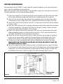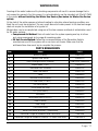
1
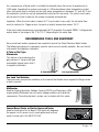
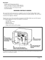
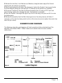
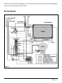
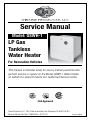
Service Manual
Model: GSWH-1
LP Gas
Tankless
Water Heater
For Recreation Vehicles
This manual is intended solely for use by trained personnel who
perform service or repairs on the Model GSWH-1 Water Heater
on behalf of a Girard Products LLC Authorized Service Center.
CSA Approved
Girard Products LLC, 1361 Calle Avanazado, San Clemente CA 92673 U.S.A
Service Manual Part No. 1GWH9405 • 9/7/2010
Patent Pending
TABLE OF CONTENTS
Service Manual - Model GSWH-1
Title
Page
1. Product Identification ............................................................................................. 3
2. Description and Features.........................................................................................4
3. Normal Operation ...................................................................................................5
4. Recommended Tools and Equipment........................................................................6
5. Removing Controls Housing ....................................................................................7
6. Schematics and Diagrams
a. Ladder Diagram..............................................................................................8
b. Wiring Diagram ..............................................................................................9
7. Circuit Board Operation .........................................................................................10
8. Exploded View ......................................................................................................12
9. Troubleshooting Guide ..........................................................................................12
10. Circuit Board Troubleshooting ................................................................................13
11. General Failures and Possible Causes and Remedies...............................................14
12. Routine Maintenance ............................................................................................16
13. Winterization ........................................................................................................17
14. Spare Parts List ....................................................................................................17
15. Flat Rate Schedule ...............................................................................................18
16. Limited Warranty (2 years) ....................................................................................19
17. Service Procedures ..............................................................................................20
Page
2
PRODUCT IDENTIFICATION
Water Heater Part Number:
Door Part Number:
Serial Number Location:
1GWH / 1GWHAF (w/ Winter Use Device)
1GWHD
On Rating Label affixed on the inside right of the Controls Housing.
Figure 1
Specifications
The main performance specifications of the Model GSWH-1 are:
BTU/HR
27,000 – 34,000
Fuel
Propane (LP Gas)
Inlet Pressure
10.5” WCI Min to 14” WCI Max
Manifold Pressure
8” – 10” WCI
Power Input
12VDC < 3 amp
Water Operating Pressure
125 PSI Max
Max Water Temperature
125 º F
Dimension
Width: 12.5” - Height: 12.5” - Depth 15.5”
Shipping Weight
22 lbs
Page
3
DESCRIPTION AND FEATURES
The Girard Products GSWH-1 LP Gas Tankless Water Heater is designed to meet ANSI Z21.10.32004 and CSA 4.3-2004 and is certified by the Canadian Standards Association (CSA) to meet
these standards for use in recreation vehicles.
The design of this product differs from the traditional storage tank water heater units found in
RVs. More specifically:
• The Girard Tankless Hot Water System uses a finned copper heat exchanger and nine high efficiency blade burners
• The Motor Aided Induced Draft enhances combustion for increased efficiency and improved wind resistance
• A Dual BTU Gas Valve optimizes the output temperature range based on the temperature of the input cold water and water flow
When properly installed in a Recreation Vehicle the Girard Tankless Water Heater is connected to:
• The RV’s cold water system with its water input from a pressurized (45 psi) source such as a shore connection or a water storage tank with water pump.
• The RV’s hot water system (i.e. faucets and shower)
• The RV’s LP Gas system capable of supplying the rated BTU requirement.
• The RV’s 12VDC Electrical power distribution panel on a 10 amp fused circuit
Please refer to the Owners Manual supplied with the unit for further information. The Owners
Manual will allow you to verify if the unit is properly installed and the connections are within the
following recommended parameters:
• The pressure of the water supply is between 40 and 60 psi for normal operation
• The LP Gas system is operating within the inlet pressure limits indicated on the rating label (10.5” and 14” WC)
• The DC Voltage applied is greater than 11.5 and less that 14 VDC
Figure 2
Page
4
NORMAL OPERATION
A tankless water heater, also referred to as an “on demand” water heater, rapidly heats water as
it flows around and through the heat exchanger. The output water temperature depends on the
temperature of the input water and the flow established at the faucet by the user; the faster the
flow, the cooler the water; the slower the flow, the hotter the water.
The gas control valve of the GSWH-1 and the GSWHAF-1 features a dual BTU solenoid that can
operate in ‘High’ mode (34,000 BTUs) or ‘Low’ mode (27,000 BTUs) depending on the input
temperature of the cold water. Colder water (65°F or less) causes the burner to operate in
‘High’. Warmer water (70°F or more) causes the burner to operate in ‘Low’. NOTE: When the
input water temperature is between 65°-70°F the unit may operate in ‘High’ or ‘Low’ depending
upon precise thermostat settings. A thermostat setting may vary +/- 5°F.
Prior to normal operation the user must ensure that all air has been purged from the water lines,
the Water Heater Power Switch is in the ‘ON’ position and the REMOTE Mode Switch (see below)
is set in the desired position (AUTO or LO). The 12VDC power is normally left ON while the RV is
in use with no use of LP gas. In many cases the switch may be set to ‘On’ the entire camping
season. This will not harm the unit in any way.
To start the water heater the user should fully open the hot water faucet, wait for hot water to
flow and decrease the flow (which results in hotter water) to obtain the temperature desired.
Note: although the Girard tankless water heater is instantaneous, the water in the system (pipes)
must be purged before the user will feel hot water at the faucet. Thus, the further the water
heater is located from the faucet/shower the longer it will take for the user to feel hot water. The
ideal location for any water heater is in the center of the coach.
During normal operation the hot water faucet behaves somewhat like a typical mixing valve: it
(faucet) increases the water temperature when turned clockwise (reducing the water flow) and
decreases the water temperature when turned counterclockwise (opening and increasing the
water flow).
The user may mix the hot water with cold water, but normally this is not recommended: The
increased total flow (Hot plus Cold) will reduce the inlet pressure; which in turn, reduces the flow
of water through the heat exchanger of the water heater: this will cause the hot water output
temperature to increase defeating the effect of the cold water. In some cases adding cold water
may result in limiting. (See last paragraph, this section)
When the Mode switch is set to AUTO, a thermostat will cause the burner to switch automatically
from High to Low when the inlet water temperature goes above 70 ºF and from Low to High
when it goes below 65 ºF. Note: A thermostat setting may vary +/- 5°F.
If the output temperature exceeds 123 ºF an Emergency Cut-Off (ECO) thermostat will shut
down the unit to prevent scalding; this operation is both normal and desirable and is commonly
referred to as “limiting”.
Page
5
As a convenience, a Mode switch is installed to manually force the burner to operate only in
LOW mode. Operating the system exclusively in LOW mode allows better temperature control
when inlet water flow is minimal and the inlet water temperature is between 70° and 65 ºF and
the automatic control has not yet automatically switched to Low mode. The switch must manually be reset to Auto in order for the system to operate automatically.
Important: When the inlet water is below 50 ºF (input water is very cold), the hot water flow
must be reduced to .75gpm or less .to reach an output temperature above 100 ºF.
If the input water temperature is approximately 60ºF or greater, the model GSWH-1 will generate
output water in the range of 95 °F to 120 °F depending on the water flow.
RECOMMENDED TOOLS AND EQUIPMENT
No unusual tools and/or equipment are needed to service the Girard Tankless Water Heater.
The following equipment is commonly used for service and is readily available. Be sure that all
instruments are regularly calibrated.
U-Tube or Dial Type
Manometer
This device is for measuring the
gas pressure. If using a dial type
manometer please insure that it
is regularly calibrated.
U-Tube Manometer
Dial Type Manometer
Gas Leak Test Solution
There are many inexpensive solutions on the market that bubble when applied to fittings where
a leak is present.
Multimeter
Used for testing Continuity, Voltage, Current (AC/DC) and Resistance. With
a good quality Multimeter you can verify voltage problems and defective
components. The entire electronic system can be tested with this meter.
Fenwal Board Tester or Similar Approved Tester
Used for testing the Circuit Board. This tester will diagnose
the power circuit, sense circuit, spark igniter and lock-out
mode. Fenwal part # 05-080224-009)
ON
VALVE
CHECK
CURCUIT BOARD TESTER
OFF
IGNITER
OFF
REMOTE
FLAME
Page
6
Hand Tools:
• Phillips and flat head screw drivers
• 9/16”, 3/4” and 13/16” S.A.E. open wrenches
• 7mm and 5.5mm nut drivers and/or wrenches.
• Needle nose pliers, wire crimp and cutter.
• Leak Test Solution.
REMOVING CONTROLS’ HOUSING
No unusual tools and/or equipment are needed to service the Girard Tankless Water Heater.
The following equipment is commonly used for service and is readily available. Be sure that all
instruments are regularly calibrated.
To gain easy access to the serviceable components of the Water Heater you must first remove
the Controls’ Housing that shields and supports the following:
• Circuit Board
• Dual BTU Gas Control
• Main Gas Line
• Ground connections
• Power switch with the LED indicator
Figure 3
1. Loosen the Power Strain Reliever nut at the back of the unit to allow the wiring harness to be
pulled into the housing as needed.
Page
7
2. Remove the Hex Nuts, Lock Washers and Washers, along the lower edge of the Control
Housing and set aside for re-assembly.
3. Reach inside along the left side of the housing but behind the Controls’ Housing and locate
the small Wing Nut along the side wall (item 2). Remove and set aside for re-assembly.
4. Disconnect the Burner Tube from the Burner Assembly (item 3) using a 9/16” open end
wrench being careful not to damage the tube. Set aside for re-assembly.
5. Lean the Controls’ Housing to the right to slip it out of the wing nut’s post and lift it to clear
the bottom posts.
6. Remove the assembly from the Main Housing as far as the wiring harness will allow. If
necessary cut the wire ties being careful not to cut the wires (be sure to replace them (wire ties)
when the job is done).
SCHEMATICS AND DIAGRAMS
The following schematics and diagrams will help to provide a better understanding of the
operation of the Model GSWH-1 Water Heater and to trouble shoot the most common
malfunctions.
Figure 4
Page
8
Please refer to the electrical diagram for a functional understanding of the electrical components
and of the Circuit Board control functions.
Wiring Diagram
Figure 5
Page
9
CIRCUIT BOARD OPERATION
When the user opens a Hot Water faucet, water starts flowing through the unit and activates the
Flow Switch which in turn activates the Relay; this applies 12VDC power to the ECO (Emergency
Cut-Off Thermostat) and to the “Heat Demand” Connection (5) of the Circuit Board (see below).
Change to: ….ECO (Emergency Cut-Off Thermostat) and to the ‘TH’ Connection (2) of the Circuit
Board.
Power is then applied to the Sail Switch that is open when there is no air flow from the blower.
The ECO is normally closed. The Circuit Board starts the blower and verifies that the Sail Switch
closes: when this occurs the Circuit Board will sense the 12VDC at the Circuit Board indicating
that there is sufficient air flow for combustion. The circuit is now complete.
Try For Ignition (TFI)
The Circuit Board is now ready to try for ignition and applies power to the gas valve through
connection (4) and without delay generates a spark of five (5) seconds duration at the igniter. If
the Circuit Board does not sense flame at the spark igniter, the gas valve is de-energized and
an internal post purge of 15 seconds will occur before a second try is attempted. Two additional
tries will be attempted and if no flame is detected in the process the Circuit Board goes into
LOCKOUT mode and will make no further attempt to light. Once the system has entered lockout
mode, it must be reset. To reset the water heater, turn OFF power to the water heater OR close
the faucet (removing the demand for hot water for a period of five (5) seconds.
Figure 6
P a g e 10
Whenever the Circuit Board senses flame during the ignition trials, sparking stops and the Gas
Valve remains energized. The Water Flow Switch, the Sail Switch and the Burner flame are
constantly monitored to assure that the system continues to operate properly.
When the Hot Water faucet is closed and the Flow Switch opens, the demand for heat ends and
the Gas Valve is de-energized immediately; after the post purge and cool off period of 90 +/seconds the blower is turned off.
Flame Failure
If the established flame signal is lost while the burner is operating, the control will sense this
and respond within 0.8 seconds. The gas valve will stay energized and the Ignition Spark will
be energized in an attempt to relight the burner (trial for ignition). If the burner does not light,
the control will make two more attempts to relight and then go into lockout (See Try for Ignitionpage 10). If flame is established.
Combustion Airflow Problems
If the airflow signal is lost, or the ECO opens during heat mode, the gas valve is immediately
de-energized and the blower stays on. If the switch closes again, a normal ignition sequence
will resume. If not and this condition persists for more than five minutes, the control will enter
lockout (See Try for Ignition - page 10) with the blower off.
Water Heater LED Diagnostics
If the water heater stops operating normally, check the LED indicator on the user panel located
behind the water heater door. If the LED is lit or blinking, consult the list below to help diagnose
the fault detected by the Circuit Board:
• Steady On –
• 1 Flash –
• 2 Flashes –
• 3 Flashes –
• 4 Flashes –
• 5 Flashes –
Internal Control Fault
Air Fault
Flame Detection Error
Lockout
N/A; Reserved for future diagnostics
Low voltage
The pattern will be repeated at intervals of 3 seconds.
P a g e 11
TROUBLE SHOOTING GUIDE
This section includes the most common symptoms that may be found in a model GSWH-1 that
is not operating normally. Please refer to the following drawing to locate the components in the
unit:
Limit Switch
Exhaust Collector
Blower Motor Assembly Support
Sail Switch
Circuit Board (Fenwal)
Heat Exchanger
Housing
Diagnostic LED
Exhaust Tube
Relay
Wire
Connections
Hot Water
Flow
Switch
Cold Water
Gas Burner
Auto-Lo Thermostat
Figure 7
Gas Control Valve
Power Switch
Anti-Freeze Thermostat
Burner Manifold
Control Panel Housing
Door Flange
Door
EXPLODED VIEW OF MODEL GSWH-1 AND MAJOR COMPONENTS IDENTIFICATION
NOTICE:
Before starting the troubleshooting steps suggested below verify that:
• There is power connected to the water heater
• The power switch is in the ON position
• The wiring is not damaged in any way
• All connectors are plugged in (no dangling connectors)
• Water flowing through the unit when you open a hot water faucet
• The Sail Switch is moving freely (forward and backward)
• The gas is connected and the gas tank is not empty
P a g e 12
CIRCUIT BOARD TROUBLESHOOTING
The Circuit Board is the electronic controller for the Water Heater. It is very reliable but it is often
diagnosed improperly and replaced. Note: in all cases the replacement of the Circuit Board is the
last item. We provide here a list of symptoms and their possible causes to help you to determine
if the problem is due to a malfunction of the board or other components.
1. Dead
a. Fuse/Circuit Breaker Bad
b. Converter/battery bad
c. Mis-wired – Check ‘On/Off’ Switch for Incoming Power
d. No voltage @ POWER or BLOWER connections - Check for Broken Wire
e. Bad circuit board: CONFIRM with Approved Board Tester such as Fenwal
part # 05-080224-009) – Replace
2. Flow Valve Activated - No Blower Output
a. Mis-wired or Failed Sail Switch - Check Wiring
b. Check Relay
c. Check ECO
d. Check Wiring to Board
e. Defective or Stuck Flow Switch: Tap with Wrench; If Problem not Solved, Replace Flow Switch
f. Bad circuit board: CONFIRM with Approved Board Tester such as Fenwal
part # 05-080224-009) - Replace
3. Sail Switch Input Okay - No Trial for Ignition
a. Mis-wired – Confirm Wiring and Connections
b. Check Sail Switch for Continuity
c. Bad circuit board: CONFIRM with Approved Board Tester such as
Fenwal part # 05-080224-009) - Replace
4. Gas present but no Spark
a. Misaligned Electrode – Ensure Gap Between Electrode Tip and Burner Blade is 1/8” and into Path of Flame
b. Check for Continuity on Electrode High Voltage Cable
c. Check for Coil on Circuit Board
d. Bad circuit board: CONFIRM with Approved Board Tester such as
Fenwal part # 05-080224-009) - Replace
5. Spark present but no Gas
a. Check Gas Supply
b. Check Valve Connections
c. Check for Proper Voltage - Minimum of 10.5 VDC
d. Check Edge Connectors for oxidation - Clean and Replace
e.Check Resistance (ohms) Draw on Coils - Should be 30 - 50 ohms
P a g e 13
6. Flame okay during trial for ignition (TFI), no flame sense (after TFI)
a. Check Electrode and High Voltage Wire for Continuity
b. Poor ground at burner
c. Bad circuit board (check flame current); CONFIRM with Approved Board Tester such as Fenwal part # 05-080224-009) - Replace
GENERAL FAILURES AND POSSIBLE CAUSES AND REMEDIES
1. No Blower, no Spark and no Gas
a. No or Low Voltage: Correct Power Supply - Minimum 10.5 VDC
b. Defective ON/OFF switch: Check for Power Coming into Switch; If no Power, Replace Switch
c. Defective or Stuck Flow Switch: Tap with Wrench; if Problem not Solved, Replace Flow Switch
d. Check Relay
e. Check ECO
f. Dirty Edge Connector on Circuit Board: Clean Edge Connector
g. Defective circuit board CONFIRM with Approved Board Tester such as Fenwal part # 05-
080224-009) - Replace
2. No Spark and No Gas (Blower Operating)
a. Low voltage: Correct Power Supply - Minimum 10.5 VDC
b. Check for Flow of Water
c. Check Relay
d. Check ECO
e. Check for Flow of Power OUT of Sail Switch to Circuit Board
f. Dirty edge connector on circuit board: Clean edge connector
g. Defective circuit board: Confirm with Approved Board Tester such as Fenwal part # 05-
080224-009) - Replace
3. Water Heater Lockout - Spark present but no gas
a. Check Gas Pressure: Set inlet pressure at a Minimum 11˝ W.C. with Two or More Gas Appliances Running.
b. No or Low Voltage: Correct power supply - 10.5 VDC Minimum
c. Loose Wire Connections on Gas Valve. Confirm Connections
d. Test Resistance of Coils - Confirm 30 - 50 ohms
e. Defective gas valve: Replace Coils or Gas Valve
f. Dirty connector on Circuit Board: Clean Edge Connector
g. Defective circuit board: CONFIRM with Approved Board Tester such as Fenwal
part # 05-080224-009) - Replace
P a g e 14
4. Water Heater Lockout – Gas present but no Spark
a. High Tension Lead Wire Loose: Secure Wire Connection on Circuit Board
b. Poor Ground Connection at Burner: Secure Ground Connection to Main Burner
c. Improper Electrode Gapping: Re-position Spark Gap Between Electrode Tip and Burner Blade to 1/8˝ and into Path of Flame
d. Dirty Electrode: Clean Electrode
e. Wires Loose in Electrode Porcelain: Replace Electrode
f. Cracked Porcelain on Electrode: Replace Electrode
g. Defective circuit board. CONFIRM with Approved Board Tester such as Fenwal part # 05-
080224-009) - Replace
5. Water Heater Lockout – Gas and Spark Present
a. Check Gas Pressure: Set inlet pressure at a Minimum 11˝ W.C. with Two or More Gas Appliances Running.
b. No or Low Voltage: Correct power supply - 10.5 VDC Minimum
c. Poor Electrical Ground: Secure Electrical Ground
d. Dirty Electrode: Clean Electrode
e. Partial Obstruction in Main Burner: Check for Complete Ignition of Burner Blades through Sight Hole. Remove any Obstructions.
f. Partially Obstructed Burner Manifold: Clean Burner Orifices; Replace if Necessary
g. Dirty Connector on Circuit Board: Clean Edge Connector
h. Defective circuit board. CONFIRM with Approved Board Tester such as Fenwal part # 05-
080224-009) - Replace
6. Erratic or Uneven Burner Flame
a. Check Gas Pressure: Set inlet pressure at a Minimum 11˝ W.C. with Two or More Gas Appliances Running
b. Partial Obstruction in Main Burner: Check for Complete Ignition of Burner Blades through Sight Hole. Remove any Obstructions
c. Obstructed Exhaust Tube Grill. Inspect and Remove any Obstruction
d. Partially Obstructed Burner Manifold: Clean Burner Orifices; Replace if Necessary
7. Excessive or Insufficient Water Temperatures; Water Not Hot or Water Cold
a. Air is present in water lines: Purge Air from Water Lines
b. Thermostat not Seated Against Sensing Tab: Reseat Thermostat and Add Thermal Paste to Insure Good Contact
c. Defective Thermostat: Replace Thermostat
d. In Case of Excessive Temperature, Verify that the Maximum Flow is not Limited by a Flow Restrictor
P a g e 15
ROUTINE MAINTENANCE
We recommend that the GSWH-1 water heater be inspected regularly by the user and at least
once a year by a qualified service technician.
Before an inspection make sure that the LP Gas and Water supply are connected and turned on.
A routine inspection must include the following items:
1.Inspect the integrity of the sealing (caulking or tape) between the side wall and the door of the water heater and make sure that the unit is solidly mounted to the vehicle.
2.Verify that the air inlet openings (louvers) are completely open and clear of any debris including mud, leaves, twigs, insects etc. Remove all obstructions to allow full air flow.
3.Inspect the Exhaust tube and make sure that it is also unobstructed and that the Exhaust screen is clean.
4.Open the cover and verify that no debris or extraneous combustible materials are present anywhere (especially in the area of the burner and the gas controls); remove any item present and wipe clean the bottom of the housing.
5.Inspect the interior surface of the housing for any cracks or corroded areas that could allow penetration of gases into the interior of the vehicle. Check especially around the Hot Water, Cold Water, Gas and electrical connections.
6.Check that all wire connections are firmly in place and there are no signs of chafing or cracks on the wire insulation. Note that the spark ignition cable between the Circuit Board and the igniter is securely in place and not shorted to any metal component.
7.At least once a year activate the Relief Valve by lifting the lever on top of the valve.
MAKE SURE THAT THE WATER HEATER HAS NOT BEEN ON RECENTLY AND THE HOT WATER OUTLET IS COLD.
8.Turn on the power to the water heater and open a hot water faucet to inspect the flame of the burner. The flame should be of the normal bluish appearance that indicates proper combustion. This can be accomplished by observing the flames through the sight hole
and looking at the burner under the edge of the heat exchanger (See Figure 9.).
Flame
Sight
Hole
Figure 9
Flame at top
of burner
P a g e 16
WINTERIZATION
Freezing of the water heater and its plumbing components will result in severe damage that is
not covered by warranty. For this reason it is not advisable to use the standard unit (Part# 1GWH)
in the winter without installing the Winter Use Device (See below for Winter Use Device
option).
At the start of the winter season or before traveling to a location where freezing conditions are
likely the unit must be winterized. The very small amount of water present in the heat exchanger
does not require the installation of a bypass kit.
Winterization can be accomplished using one of the two common methods of winterization used
for RV water systems:
• Compressed Air Method: Drain all water from the system opening one tap at a time and using compressed air to purge all remaining water.
• RV Anti-freeze Method: Follow the recommendations of the Recreation Vehicle manufacturer and fill the system with a non toxic anti-freeze. Make sure that the antifreeze flows from each tap to complete the process.
PARTS BREAKDOWN
Item
Name
Part #
1
Burner Assembly
1GWH1000
2
Igniter/Flame sensor
1GWH6310
3
Heat Exchanger/Exhaust Assembly
1GWH2000/1GWH3000
4
Blower Motor 12 VDC
1GWH6200
5
Cold Water Inlet Assembly
1GWH5100
6
Water Flow Switch
1GWH7100
7
Relay
1GWH6800
8
Hot Water Outlet Assembly
1GWH5300
9
P/T Relief Valve (1/2"NPT)
1GWH7200
10
Gas Valve Control
1GWH6100
11
Circuit Board and cover
1GWH7300
12
ECO (Limit Switch)
1GWH6500
13
Sail Switch
1GWH6600
14
Power/Mode Switch (ON/OFF)
1GWH6700
15
Door Assembly
1GWH4400
16
Door Flange
1GWH4300
17
Flue Exhaust tube
1GWH4700
18
Winter Use Device for GSWH-1 (Aftermarket)
1GWH9404
19
Conversion Flange for Atwood 6 Gallon Polar White
1GWHDA6
20
Conversion Flange for Atwood or Suburban 10 Gallon Polar White
1GWHDAS10
Figure 10
P a g e 17
FLAT RATE SCHEDULE
Effective 01/01/2010
TIME ALLOWANCE
(in hours calculated at 1/10th hour - 6 minutes)
General Trouble Shooting Diagnostic Testing:
18 minutes (.30 hour)
Replacement of Component:
Complete Water Heater
Door Frame (Flange)
Flue Tube
Exhaust Bracket
Control/Gas Housing Plate
Circuit Board Gas Control Valve w/inlet fitting
LP Gas tube (from valve to burner)
Burner
P/T Relief Valve
Hot Water Outlet Manifold Assembly
Flow Switch
Cold Water Inlet Manifold Assembly
ECO
Sail Switch
Relay
Power (On/Off) Switch
Mode Switch (Hi/Low Burner)
Diagnostic LED
Winter Use Control Unit
Winter Use Thermostat
Hours
1.00
.50
.10
.20
.50
.40
.40
.10
.40
.40
.20
.40
.30
.10
.20
.30
.10
.10
.10
.30
.10
Minutes
60
30
6
12
30
24
24
6
24
24
12
24
18
6
12
18
6
6
6
18
6
Figure 11
• For any component replacement that does not appear on the above list, contact Girard Products LLC for authorization and instructions.
• To process a warranty claim the Service Center must be an authorized Girard Products, LLC Service Center.
• Authorized Service Centers must obtain prior approval for work that exceeds the flat rate time allowances.
• Operational failure caused by improper installation or the use of non GSWH-1 components will result in the warranty claim being denied.
P a g e 18
GIRARD PRODUCTS, LLC GSWH-1 WATER HEATER
TWO YEAR LIMITED WARRANTY
Girard Products, LLC warrants to the original owner (purchaser) that this product will be free of defects
in material or workmanship for a period of two years from the original date of purchase whether or not
actual usage begins on that date. Girard Products liability hereunder is limited to the replacement of the
part(s), repair of the part(s), or replacement of the product or part(s) with a reconditioned or new product/
part(s) at the discretion of the Girard Products. This warranty is void if the product has been damaged by
accident, unreasonable use, misuse, neglect, tampering or other causes not arising from defects in material
workmanship. This limited warranty extends to the original owner of the product only, is not transferable
and is subject to the following conditions:
1. For a period of two years from the date of purchase, Girard Products will replace any parts that are found
defective and will pay a warranty service allowance directly to the recommended Girard Products Water
Heater Service Center at rates mutually agreed upon between Girard Products and its recommended
service centers. As an owner, you are required to provide proof of purchase date through a Bill of Sale or
other appropriate record.
2. Replacement parts will be shipped FOB the shipping point within the Continental United States, Alaska
and Canada to the recommended service center performing such repairs. All freight, shipping and
delivery costs shall be the responsibility of the owner.
3. Service calls to customer’s location are not considered part of these charges and are, therefore, the
responsibility of the owner.
4. Before having warranty repairs made, confirm that the service center is a recommended service center
for Girard Products, LLC Water Heaters. DO NOT PAY THE SERVICE CENTER FOR WARRANTY REPAIRS
WITHOUT PRIOR APPROVAL FROM GIRARD PRODUCTS, LLC; SUCH PAYMENTS WILL NOT BE
REIMBURSED.
5. The defective parts (or water heater) become the property of Girard Products, LLC and may need to be
returned to Girard Products Technical Support Department. Girard Products reserves the right to examine
the alleged defective part or water heater. All returned parts and/or product must be individually tagged with
the water heater’s model, serial number, date of installation and detailed explanation of defect.
6. This warranty does not cover the following items classified as normal maintenance:
• Adjustment of gas pressure
• Cleaning or adjustment of flue
• Adjustment of pressure-temperature relief valve
• Cleaning, replacement, and adjustment of burner orifice
7. This warranty applies only if the unit is installed according to the installation instructions provided and
complies with local and state codes.
8. The warranty period on replacement parts (or water heater) is the unused portion of the original warranty
period or ninety (90) days, whichever is greater.
9. This limited warranty does not apply to damage caused by accident, abuse, misuse
(including damage caused by service performed by anyone who is not a Girard Products LLC
recommended installer), misapplication, alterations, modifications, water damage or freezing.
10. THIS WARRANTY AND THE REMEDIES SET FORTH ABOVE ARE EXCLUSIVE AND IN LIEU
OF ALL OTHER WARRANTIES, REMEDIES AND CONDITIONS, WHETHER ORAL OR WRITTEN,
EXPRESS OR IMPLIED. GIRARD PRODUCTS LLC SPECIFICALLY DISCLAIMS ANY AND ALL IMPLIED
WARRANTIES, INCLUDING WITHOUT LIMITATION, WARRANTIES OF MERCHANTABILITY AND
FITNESS FOR A PARTICULAR PURPOSE. IF GIRARD PRODUCTS LLC CANNOT LAWFULLY DISCLAIM
IMPLIED WARRANTIES UNDER THE LIMITED WARRANTY, ALL SUCH WARRANTIES, INCLUDING
WARRANTIES OF MERCHANTABILITY AND FITNESS FOR A PARTICULAR PURPOSE ARE LIMITED IN
DURATION TO THE DURATION OF THIS WARRANTY.
P a g e 19
NO RESELLER, AGENT, OR EMPLOYEE IS AUTHORIZED TO MAKE ANY MODIFICATION, EXTENSION
OR ADDITION TO THIS WARRANTY. GIRARD PRODUCTS LLC IS NOT RESPONSIBLE FOR DIRECT,
SPECIAL, INCIDENTAL OR CONSEQUENTIAL DAMAGES RESULTING FROM ANY BREACH OF
WARRANTY OR CONDITION, OR UNDER ANY OTHER LEGAL THEORY, INCLUDING BUT NOT LIMITED
TO LOST PROFITS, DOWNTIME, INCONVENIENCE, GOODWILL, EXPENSES FOR TRAVEL, LODGING,
DAMAGE TO OR REPLACEMENT OF EQUIPMENT AND PROPERTY.
11. Some states and provinces do not allow the exclusion or limitation of incidental or consequential
damages or exclusion or limitations on the duration of implied warranties or conditions, so the above
limitations or exclusions may not apply to you. This warranty gives you specific legal rights, and you may
also have other rights that vary by state or province.
12. Replacement parts purchased outside of the original water heater warranty carry a 90 day limited
warranty.
13. Girard Products provides no warranty for products installed or warranty claims originating outside the
continental United States, Alaska, Hawaii and Canada.
Service
Your Girard Tankless Water Heater is manufactured to the highest standards and is designed to provide
years of trouble free use but in the event you require service please follow the steps outlined below.
Remember as an owner, you are required to provide proof of purchase date through a Bill of Sale or other
appropriate record.
1.If your RV has its original water heater and is still under the RV manufacturer’s warranty, follow the steps suggested by your dealer or the manufacturer of your RV.
2. Contact Girard Products Water Heater Service Center or call the Girard Products Technical Support Department at 949-259-4024 or visit our website at www.greenrvproducts.com for a local recommended service center.
3.Call the service center, describe your problem and make an appointment, if necessary. SERVICE CALLS TO CUSTOMER LOCATION ARE THE RESPONSIBILITY OF THE OWNER. DO NOT PAY THE SERVICE CENTER FOR WARRANTY REPAIRS WITHOUT PRIOR APPROVAL FROM GIRARD PRODUCTS, LLC; SUCH PAYMENTS WILL NOT BE REIMBURSED. Be sure to provide purchase documentation regarding your Girard Water Heater.
This Girard Products Water Heater is designed for use in recreation vehicles for the purpose of
heating water as stated in the “rating plate” attached to the water heater. Any other use, unless
authorized in writing by the Girard Products Engineering Department, voids this warranty.
GIRARD PRODUCTS, LLC
1361 CALLE AVANZADO, SAN CLEMENTE, CA 92673
949-259-4024 • www.greenrvproducts.com
WARRANTY/GSWH-1 (7/20/2010)
P a g e 20