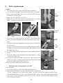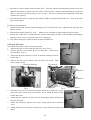
1
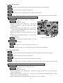
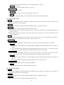
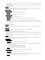
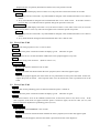
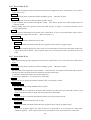
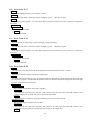
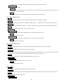
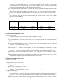
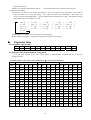
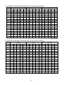
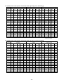
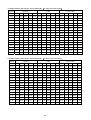
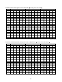
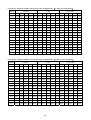
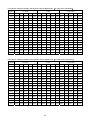
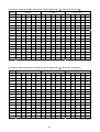
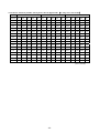
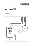
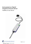
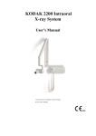
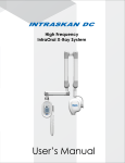
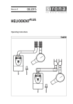
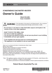
MODEL 303
DENTAL X-RAY
Service Manual
Ver.1
R
○
Index
1.Adjustments required after parts replacement ......................................... 4
2.Error Code............................................................................................................................. 4
2.1
2.2
2.3
2.4
2.5
2.6
2.7
2.8
2.9
2.10
2.11
2.12
2.13
2.14
2.15
2.16
2.17
2.18
2.19
2.20
2.21
Error Code: E.00 ........................................................................................................................4
Error Code: E.01 ........................................................................................................................4
Error Code: E.02 ........................................................................................................................5
Error Code: E.03 ........................................................................................................................5
Error Code: E.05 ........................................................................................................................6
Error Code: E.06 ........................................................................................................................6
Error Code: E.07 ........................................................................................................................7
Error Code: E.08 ........................................................................................................................8
Error Code: E.09 ........................................................................................................................8
Error Code: E.10 ......................................................................................................................9
Error Code: E.11.......................................................................................................................9
Error Code: E.12 ......................................................................................................................9
Error Code: E.14 ......................................................................................................................9
Error Code: E.15 ....................................................................................................................10
Error Code: E.16 ....................................................................................................................10
Error Code: E.17 .................................................................................................................... 11
Error Code: E.19 .................................................................................................................... 11
Error Code: E.20 .................................................................................................................... 11
Error Code: E.22 ....................................................................................................................12
Error Code: E.23 ....................................................................................................................12
Others ......................................................................................................................................12
3. Setting Mode.................................................................................................................. 13
3.1
3.2
3.3
3.4
3.5
3.6
3.7
3.8
3.9
Film type, digital mode and priority selection.....................................................................13
Tube current adjustment value ...............................................................................................14
Tube voltage adjustment value................................................................................................14
Buzzer ........................................................................................................................................15
Manual setting of preheating power .......................................................................................15
Automatic adjustment of preheating power ..........................................................................15
Lock mode .................................................................................................................................16
Standard density value for each tooth ....................................................................................16
Overview mode .........................................................................................................................16
-2-
4. Exposure time ............................................................................................................... 17
4.1 Assignable exposure time.........................................................................................................17
4.2 Exposure time in the automatic setting mode........................................................................17
4.2.1 Film number and exposure time in film mode(for short cone/4 mA/60 kV) ..............17
4.2.2 Film number and exposure time in film mode(for long cone/4 mA/60 kV) ................18
4.2.3 Film number and exposure time (for short cone/7 mA/60 kV) ...................................18
4.2.4 Film number and exposure time (for long cone/7 mA/60 kV).....................................19
4.2.5 Film number and exposure time (for short cone/4 mA/70 kV) ...................................19
4.2.6 Film number and exposure time (for long cone/4 mA/70 kV).....................................20
4.2.7 Film number and exposure time (for short cone/7 mA/70 kV) ...................................20
4.2.8 Film number and exposure time (for long cone/7 mA/70 kV).....................................21
4.2.9 Sensor sensitivity number and exposure time (for short cone/4mA/60kV)...................21
4.2.10 Sensor sensitivity number and exposure time (for long cone/4mA/60kV) ..................22
4.2.11 Sensor sensitivity number and exposure time (for short cone/7mA/60 kV) ................22
4.2.12 Sensor sensitivity number and exposure time (for long cone/7mA/60kV) ..................23
4.2.13 Sensor sensitivity number and exposure time (for short cone/4mA/70 kV) ...............23
4.2.14 Sensor sensitivity number and exposure time (for long cone/4mA/70kV) ..................24
4.2.15 Sensor sensitivity number and exposure time (for short cone/7mA/70 kV)................24
4.2.16 Sensor sensitivity number and exposure time (for long cone/7mA/70 kV) .............. 25T
5. Parts replacement ........................................................................................................26
5.1
5.2
Head...........................................................................................................................................26
Power PC board........................................................................................................................27
-3-
1. Adjustment required after parts are replaced
Following two kind of adjustments are necessary if head or PC board is replaced.
Replaced part
Adjustment
Change the CP value as indicated on the head
yoke.
[Refer to section 3.3.]
Automatic adjustment of preheating power
[Refer to section 3.6.]
Head
Timer PC
board
Power PC
board
Filter PC
board
Necessary
Necessary
Not
Necessary
Not
Necessary
Necessary
Necessary
Necessary
Not
Necessary
2.Error Code
2.1
Error Code: E.00
Meaning
The exposure switch was released during x-radiation.
To release
Press either button for teeth selection.
Measures
Explain that the operator must continue pressing the exposure switch until the exposure light goes out (and
alarm stops sounding).
If not resolved
Possible cause
Contact fault occurred in the exposure switch or contact failure occurred due to disconnection in a curl cord
of a hand switch in the middle of exposure.
Verification
Replace the exposure switch or the hand switch from the timer PC board and check continuity of the
cables. (Pay special attention to the cord bush and connectors.)
Solution
Replace the exposure switch or the hand switch if any failure is found.
2.2
Error Code: E.01
Meaning
The exposure switch was pressed within three seconds after power-on.
The exposure switch was pressed within ten seconds after previous exposure.
To release
Release the exposure switch to restore the original state.
Solution
Explain that the operator must wait to press the exposure switch during three seconds after power-on (until the
ready light is on) and that exposure is allowed only after an interval 50 times the length of the last exposure
time.
If not resolved
Possible cause
Contact fault occurred in the exposure switch or contact failure occurred due to disconnection in a curl cord
of a hand switch in the middle of exposure.
Verification
Replace the exposure switch or the hand switch from the PC board and check continuity of the cables.
(Pay special attention to the cord bush and connectors.)
Solution
Replace the exposure switch or the hand switch if any failure is found.
-4-
2.3
Error Code: E.02
Meaning
The exposure switch was pressed when the line voltage was less than 90% of the rated voltage.
To release
Release the exposure switch to restore the original state.
Verification
Measure the voltage between L and N of the power supply terminal block.
Solution
Increase the line voltage using a step-up transformer if the supply voltage is less than 90% of the rated voltage.
If not resolved (or if line voltage is within ±10% of rated voltage.)
Possible cause 1
The monitoring voltage for power supply is misadjusted.
VR01 -PROBE
Verification (See photo 1)
①Turn off the main power switch.
②Set the multi-meter at AC voltage range. Measure the
voltage (a) between L and N of the power supply
terminal block.
③Set the multi-meter at DC voltage range. Connect the
+ probe to the TP24 (PWR-MON) and – probe to TP19
(S.G.) on the power PC board.
④Turn on the main power switch and measure the voltage
(b).
⑤Check that the calculation result of b - (a x 0.03) falls
Never touch
+PROBE
this VR.
within ±0.05 V.
Photo 1. Power PC board
Solution (See photo 1)
Adjust VR01 on the power PC board to make b = (a x 0.03).
Possible cause 2
The memory is out of order.
Verification
Check C.XX setting at overview mode. (Refer to section 3.9.)
Solution
If C.7F is displayed, memory is out of order and timer PC board should be replaced.
2.4
Error Code: E.03
Meaning
The exposure switch was pressed when the supply voltage was more than 110% of the rated voltage.
To release
Release the exposure switch to restore the original state.
Verification
Measure the voltage between L and N of the power supply terminal block.
Solution
Decrease the voltage using a step-down transformer if the supply voltage is more than 110% of the rated
voltage.
If not resolved (or if the line voltage is within the range of ±10% of rated voltage.)
Possible cause 1
The standard supply voltage is set to an abnormal value.
Verification (See photo 1)
①Turn off the main power switch.
②Set the multi-meter at AC voltage range. Measure the voltage (a) between L and N of the power
supply terminal block.
③Set the multi-meter at DC voltage range. Connect the + probe to the TP24 (PWR-MON) and – probe
to TP19 (S.G.) on the power PC board.
④Turn on the main power switch and check the indication (b) of the voltmeter.
-5-
⑤Check that the calculation result of b - (a x 0.03) falls within ±0.05 V.
Solution (See photo 1)
Adjust VR01 on the PC board to make b = (a x 0.03).
Possible cause 2
The memory is out of order.
Verification
Check C.XX setting at overview mode. (Refer to section 3.9.)
Solution
If C.7F is displayed, memory is out of order and timer PC board should be replaced.
2.5
Error Code: E.05
Meaning
Tube current immediately before termination of exposure was less than 3 mA (when 4 mA is selected) or less
than 5.25 mA (when 7 mA is selected).
To release
Turn off the main power switch and confirm all displays go off. Then turn on again.
Verification
Make an exposure for 0.05 seconds and check the tube current.
①After exposure, do not release the exposure switch. Press the mA button twice while holding down the
exposure switch.
②Keep holding down the exposure switch and check that the T5 light is on and the indication of the
seven-segment LED.
Solution
If seven-segment LED displays not more than 2.9 mA (when 4 mA is set) or not more than 5.2 mA (when 7
mA is set), increase the setting value for h.XX. (Refer to section 3.5.)
If not resolved
Possible cause 1
If seven segment LED displays not more than 1 mA, the power PC board or the head is out of order.
Solution
1. Both the power PC board and x-ray head should be changed, if the manufactured date is Oct. 2005 or
earlier.
2. X-ray head should be changed if the manufactured date is Nov. 2005 or later. If the tube current is
not more than 1 mA after the head is replaced, change the power PC board, too.
Possible cause 2
If seven segment LED displays more than 1 mA, but not more than 2.9 mA (when 4 mA is set) or not more
than 5.2 mA (when 7 mA is set), tube current might be low at transient period of exposure.
Solution
1. Both the power PC board and x-ray head should be changed, if the manufactured date is Oct. 2005 or
earlier.
2. X-ray head should be changed if the manufactured date is Nov. 2005 or later.
Possible cause 3
The tube current adjusting value is not properly adjusted.
Solution
Increase the setting value for EP.X. (Refer to section 3.2.)
2.6
Error Code: E.06
Meaning
Tube current immediately before termination of exposure was more than 5 mA (when 4 mA is selected) or
more than 8.75 mA (when 7 mA is selected).
To release
Turn off the main power switch and confirm all displays go off. Then turn on again.
Verification
Make an exposure for 0.05 seconds and check the tube current.
-6-
①After exposure, do not release the exposure switch. Press the mA button twice while holding down the
exposure switch.
②Keep holding down the exposure switch and check that the T5 light is on and the indication of the
seven-segment LED.
Solution
If seven-segment LED displays not less than 5.1 mA (when 4 mA is set) or not less than 8.8 mA (when 7 mA
is set), decrease the setting value for h.XX. (Refer to section 3.5.)
If not resolved
Possible cause 1
The tube current adjusting value is not properly adjusted.
Solution
Decrease the setting value for EP.X. (Refer to section 3.2.)
Possible cause 2
The power PC board or the head is out of order.
Verification
Replace the head and check whether the same symptom (Error code E.06) appears again.
Solution
If the same symptom appears, the cause of the error is presumed to lie in the power PC board. In this
case, replace the power PC board. If the exposure turns out to be normal, the cause is presumed to lie in
the x-ray head.
2.7
Error Code: E.07
Meaning
Tube current during the exposure dropped to 2 mA or less (when 4 mA is set) or 3.5 mA or less (when 7 mA is
set).
To release
Turn off the main power switch and confirm all displays go off. Then turn on again.
Verification
Make an exposure for 0.05 seconds and check the tube current.
①After exposure, do not release the exposure switch. Press the mA button twice while holding down the
exposure switch.
②Keep holding down the exposure switch and check that the T5 light is on and the indication of the
seven-segment LED.
Solution
If seven-segment LED displays not more than 1.9 mA (when 4 mA is set) or 3.4 mA (when 7 mA is set),
increase the setting value for h.XX. (Refer to section 3.5.)
If not resolved
Possible cause 1
The arm cable (power line for filament of x-ray tube) is broken.
Verification
Disconnect the arm cable from the head (10P connector) and the power PC board (8P connector) and
check continuity of the cable.
1. between #4 (head side) and #4 (power PC board side)
2. between #8 (head side) and #7 (power PC board side)
3. between #9 (head side) and #8 (power PC board side)
Solution
Replace the arm in question (horizontal or balance arm) if any failure is found.
Possible cause 2
The arm cable (tube current feedback line) is broken.
Verification
Disconnect the arm cable from the head (10P connector) and the power PC board (8P connector) and
check continuity of #1 (head side) and #2 (power PC board side).
Solution
-7-
Replace the arm in question (horizontal or balance arm) if any failure is found.
Possible cause 3
If seven segment LED displays not more than 1 mA, the power PC board or the head is out of order.
Solution
1. Both the power PC board and x-ray head should be changed, if the manufactured date is Oct. 2005 or
earlier.
2. X-ray head should be changed if the manufactured date is Nov. 2005 or later. If the tube current is
not more than 1 mA after the head is replaced, change the power PC board, too.
Possible cause 4
If seven segment LED displays more than 1 mA, but not more than 1.9 mA (when 4 mA is set) or not more
than 3.4 mA (when 7 mA is set), tube current might be low at transient period of exposure.
Solution
1. Both the power PC board and x-ray head should be changed, if the manufactured date is Oct. 2005 or
earlier.
2. X-ray head should be changed if the manufactured date is Nov. 2005 or later.
2.8
Error Code: E.08
Meaning
Tube current during exposure rose to 15 mA or above.
To release
Turn off the main power switch and confirm all displays go off. Then turn on again.
Verification
Make exposures for 0.1 seconds and check whether the same symptom appears every time.
Solution
Decrease the setting value for h.XX. (Refer to section 3.5.)
If not resolved
Possible cause
The power PC board or the head is out of order.
Verification
Replace the head and check whether the same symptom (Error code E.08) appears again.
Solution
If the same symptom appears, the cause of the error is presumed to lie in the power PC board. In this case,
replace the power PC board. If the exposure turns out to be normal, the cause is presumed to lie in the
head.
2.9
Error Code: E.09
Meaning
The set value for the preheating power is abnormal when the power is turned on.
To release
Turn off the main power switch and confirm all displays go off. Then turn on again.
Solution
Set the h.XX value to “h.10” at all conditions (60 kV/4 mA, 70 kV/4 mA, 60 kV/7 mA, 70 kV/7 mA). If the
same symptom (E.09) does not appear when the power is turned on again, set the CP value (see 3.3) and
perform automatic adjustment of preheating power (see 3.6).
If not resolved
Possible cause
The timer PC board (EEPROM) is out of order.
Verification
Replace the timer PC board and check whether the same symptom (Error code E.09) appears again.
Solution
If the error code disappears, the timer PC board is presumed to be the cause. Replace it.
-8-
2.10
Error Code: E.10
Meaning
The exposure switch is already on, when the power switch is turned on.
To release
Turn off the main power switch and confirm all displays go off. Then turn on again.
Verification
Power on after disconnecting CN2 on the timer PC board and check whether the same symptom (E.10)
appears. If the hand switch is used, disconnect CN3 as well.
Solution
If the same symptom (Error code E.10) appears even after the connector is disconnected, the cause of the error
is presumed to lie in the timer PC board. In this case, replace the timer PC board. If the E.10 does not appear,
the cause is presumed to lie in the contact fault in the exposure switch. In this case, replace the exposure
switch. If a hand switch is used, connect either of the connectors and check it.
2.11
Error Code: E.11
Meaning
Tube current of 2 mA or more is detected during preheating.
To release
Turn off the main power switch and confirm all displays go off. Then turn on again.
Solution
There is a failure in the power PC board. Replace the PC board.
2.12
Error Code: E.12
Meaning
Tube current of 1 mA or more is detected when main power switch is turned on.
To release
Turn off the main power switch and confirm all displays go off. Then turn on again.
Solution
There is a failure in the power PC board. Replace the PC board.
2.13
Error Code: E.14
Meaning
Tube voltage immediately before termination of exposure was less than 50 kV (when 60 kV is set) or less than
60 kV (when 70 kV is set).
To release
Turn off the main power switch and confirm all displays go off. Then turn on again.
Verification
Make an exposure for 0.05 seconds and check the tube voltage.
①After exposure, do not release the exposure switch. Press the kV button twice while holding down the
exposure switch.
②Keep holding down the exposure switch and check that the T5 light is on and the indication of the
seven-segment LED.
Solution
If seven-segment LED displays not more than 50 kV (when 60 kV is set) or not more than 60 kV (when 70 kV
is set), increase the setting value for CP.X. (Refer to section 3.3.)
If not resolved
Possible cause
The power PC board or the head is out of order.
Verification
Replace the head and check whether the same symptom (Error code E.14) appears again.
Solution
If the same symptom appears, the cause of the error is presumed to lie in the power PC board and it
should be replaced. If the exposure turns out to be normal, the cause is presumed to lie in the head.
-9-
2.14
Error Code: E.15
Meaning
Tube voltage immediately before termination of exposure was higher than 70 kV (when 60 kV is set) or 80 kV
(when 70 kV is set).
To release
Turn off the main power switch and confirm all displays go off. Then turn on again.
Verification
Make an exposure for 0.05 seconds and check the tube voltage.
①After exposure, do not release the exposure switch. Press the kV button twice while holding down the
exposure switch.
②Keep holding down the exposure switch and check that the T5 light is on and the indication of the
seven-segment LED.
Solution
If seven-segment LED displays not less than 70 kV (when 60 kV is set) or not less than 80 kV (when 70 kV is
set), decrease the setting value for CP.X. (Refer to section 3.3.)
If not resolved
Possible cause
The power PC board or the head is out of order.
Verification
Replace the head and check whether the same symptom (Error code E.15) appears again.
Solution
If the same symptom appears, the cause of the error is presumed to lie in the power PC board. In this case,
replace the power PC board. If the exposure turns out to be normal, the cause is presumed to lie in the
head.
2.15
Error Code: E.16
Meaning
Tube voltage during exposure dropped to less than 40 kV (when 60 kV is set) or less than 50 kV (when 70 kV
is set).
To release
Turn off the main power switch and confirm all displays go off. Then turn on again.
Verification
The arm cable (main output line) may be broken. Disconnect the arm cable from the head (10P connector)
and the power PC board (2P connector) and check continuity of the cable.
1. between #10 (head side) and #1 (power PC board side)
2. between #5 (head side) and #2 (power PC board side)
Solution
Replace the arm in question (horizontal or balance arm) if any failure is found.
If not resolved
Possible cause 1
The arm cable (tube voltage feedback line) is broken.
Verification
Disconnect the arm cable from the head (10P connector) and the power PC board (8P connector) and
check continuity between #7 (head side) and #6 (power PC board side).
Solution
Replace the arm in question (horizontal or balance arm) if any failure is found.
Possible cause 2
The power PC board or the head is out of order.
Verification
Replace the head and check whether the same symptom (Error code E.16) appears again.
Solution
If the same symptom appears, the cause of the error is presumed to lie in the power PC board and it
should be replaced. If the exposure turns out to be normal, the cause is presumed to lie in the head.
- 10 -
2.16
Error Code: E.17
Meaning
Tube voltage during exposure rose to 80 kV or above.
To release
Turn off the main power switch and confirm all displays go off. Then turn on again.
Solution
If the same symptom appears, it is more likely that the power PC board is the cause. In this case, replace the
PC board.
If not resolved
Possible cause
The head is out of order.
Solution
Replace the head.
2.17
Error Code: E.19
Meaning
An over current ran the primary circuit of the high voltage transformer.
To release
Turn off the main power switch and confirm all displays go off. Then turn on again.
Solution
If the same symptom appears, it is more likely that the power PC board is the cause. In this case, replace the
PC board.
If not resolved
Possible cause
The head is out of order.
Solution
Replace the head.
2.18
Error Code: E.20
Meaning
The exposure switch was pressed when the temperature inside the head was 60℃ or higher.
To release
Release the exposure switch to restore the original state.
Solution
It is highly likely that exposures were conducted irrespective of the duties, and the temperature inside the head
rose to 60℃ or higher. Explain that the operator must wait until the temperature drops (until the ready light
becomes on) before the next exposure.
If not resolved
Possible cause 1
The arm cable (temperature sensor line) is broken.
Verification
Disconnect the arm cable from the head (10P connector) and the power PC board (8P connector) and
check continuity of #6 (head side) and #5 (power PC board side).
Solution
Replace the arm in question (horizontal or balance arm) if any failure is found.
Possible cause 2
The arm cable (signal common line) is broken.
Verification
Disconnect the arm cable from the head (10P connector) and the power PC board (8P connector) and
check the continuity between #2 (head side) and #3 (power PC board side).
Solution
- 11 -
Replace the arm in question (horizontal or balance arm) if any failure is found.
Possible cause 3
The head is out of order.
Verification
Disconnect the head connector (10P) from the arm cable and check continuity between #2 and #6
terminals in the head connector.
Solution
Replace the head if no continuity between #2 and #6 terminals is confirmed.
2.19
Error Code: E.22
Meaning
Communication between the power PC board and the timer PC board was not normal.
To release
Turn off the main power switch and confirm all displays go off. Then turn on the main power switch again.
Verification
The communication line may be broken. Check continuity of the #2 wire of the communication cable.(4P)
Solution
Replace the communication cable if any failure is found.
If not resolved
Possible cause 1
Something is wrong with the communication circuit on the timer PC board.
Solution
Replace the timer PC board.
Possible cause 2
Something is wrong with the communication circuit on the power PC board.
Solution
Replace the power PC board.
2.20
Error Code: E.23
Meaning
A button other than the exposure switch is already on when the main power switch is turned on.
To release
Release the button in question to restore the original state
Verification
It is likely that the power was turned on while another button was held down. Dismount the timer PC board
from the front cover of the sub controller and then turn on the main power switch.
Solution
Do not tighten screws too much when mounting the timer PC board.
If not resolved
Possible cause
The button on the timer PC board is out of order.
Solution
Replace the timer PC board.
2.21
Others
Symptom
Nothing was displayed on the display on the sub controller.
Verification
Check whether a fuse has been blown (F01[10A] on the filter PC board and F3[1A] on the power PC board).
Solution
Replace the fuse if it has been blown..
If not resolved
Possible cause 1
- 12 -
The communication cable (power line) is broken. * If the fuse blows again when fuse is replaced, no break
exists in the communication cable.
Verification
Check continuity of the #1 and #4 wires of the communication cable.
Solution
Replace the communication cable if any failure is found.
Possible cause 2
The power supply circuit on the timer PC board is out of order.
Solution
Replace the timer PC board.
Possible cause 3
The control power supply circuit on the power PC board is out of order.
Solution
Replace the power PC board.
Symptom
Exposure can not be made although the ready light is on.
Verification
Remove the exposure switch and the hand switch from the PC board and check continuity of the cables. (Pay
special attention to the cord bush and connectors.)
Solution
Replace the exposure switch or the hand switch if any failure is found.
If not resolved
Possible cause 1
The communication cable (exposure signal line) is broken.
Verification
Check continuity of the #3 wire of the communication cable.
Solution
Replace the communication cable.
Possible cause 2
The exposure switch circuit on the timer PC board is out of order.
Solution
Replace the timer PC board.
Possible cause 3
The exposure switch circuit on the power PC board is out of order.
Solution
Replace the power PC board.
3.Setting Mode
3.1 Film type, digital mode and priority light
(1) To enter to this mode
Hold down both of the tube current button and the tube voltage button for approximately three seconds.
(2) The status when you enter this mode
①The teeth and exposure lights are off. For patient, cone, film/digital mode, tube voltage, and tube current,
the lights for prioritized settings are on. The ready light blinks.
②On the seven-segment LED, the film speed number or the sensor sensitivity number, which was set in the
prioritized film type/digital mode, is displayed.
(3) Operation and display
①Each time you press the patient, cone, or film type button, the light of your choice is turned on. Pressing
the digital mode button turns off the film light and turns on the digital light. Thus, turn on the lights for the
settings you want to prioritize at the time of power-on.
②To change the film speed number registered in the film type, press the film type selection button to display
- 13 -
the film type you want and the press the △ or ▽ button to display the film number you want on the
seven-segment LED. If you want to change the film number of another film type, select the film type using
the film type selection button and then follow the same process as above.
③To change the exposure conditions (tube voltage or tube current) registered in the digital mode, press the
digital mode button to select the digital mode. To change the tube voltage or tube current, press the tube
voltage or tube current button and turn on the light you want. To change the sensor sensitivity number,
press the △ or ▽ button to display the sensor sensitivity number you want on the seven-segment LED.
④When you complete the change, turn on the lights for the film type/digital mode you want to prioritize at the
time of power-on. Press the T1 button for approximately one second and then an alarm sounds and the
settings are stored in EEPROM.
⑤Prioritized settings at factory are listed in table 1.
Film type
Table 1: Factory settings for priority
Patient type
Cone
Tube current
Tube voltage
a
Adult
Short
7 mA
60 kV
Film speed number
(film type a)
Film speed number
(film type b)
Sensor sensitivity
number
Digital tube
current
Digital tube
voltage
F.09
F.05
d.06
4 mA
60 kV
* F.09 is an exposure condition for speed D (Kodak ultra-speed film) and F.05 is for speed F (Kodak insight
film).
3.2 Tube current adjustment value
(1) To enter this mode
Hold down the patient/cone/film buttons for approximately three seconds.
(2) The status when you enter the mode
①The ready light blinks. The lights for teeth, patient, cone, tube voltage, exposure, film, and digital mode are
off.
②For the tube current light, 4 mA is on.
③The seven-segment LED displays “EP.X”. X represents the tube current adjustment value for 4 mA held
at the time. The standard setting is “EP.8”.
(3) Operation and display
①Press the △ or ▽ button to increase/decrease the tube current adjustment value displayed on the
seven-segment LED. Select the value you want and press the patient selection button for approximately
one second. An alarm sounds and the value is stored as a new tube current adjustment value for 4 mA.
②Press the tube current selection button and the light for 4 mA is turned off and 7 mA is turned on. Follow
the same process as above to store a new tube current adjustment value for 7 mA.
③When the change of tube current adjustment value is completed, the standard digital value for tube current
is automatically changed in conjunction with the adjustment value stored.
3.3 Tube voltage adjustment value
(1) To enter this mode
Hold down the patient/cone/film buttons for approximately three seconds.
(2) The status when you enter the mode
①The ready light blinks. The lights for teeth, patient, cone, tube current, exposure, film, and digital mode
are off.
②For the tube voltage light, 60 kV is on.
③The seven-segment LED displays “CP.X”. X represents the tube voltage adjustment value for 60 kV held
at the time. The standard setting is “CP.8”.
(3) Operation and display
①Press the △ or ▽ button to increase/decrease the tube voltage adjustment value displayed on the
seven-segment LED. Select the value you want and press the patient selection button for approximately
one second. An alarm sounds and the value is stored as a new tube current adjustment value for 60 kV.
②Press the tube voltage selection button and the light of 60 kV is turned off and 70 kV is turned on. Follow
- 14 -
the same process as above to store a new tube voltage adjustment value for 70 kV.
③When the change of tube voltage adjustment value is completed, the standard digital value for tube voltage
is automatically changed in conjunction with the adjustment value stored.
3.4 Setting the alarm
(1) To enter this mode
Hold down the T1 and T2 buttons for approximately three seconds.
(2) The status when you enter the mode
①The ready light blinks. The lights for teeth, patient, cone, tube voltage, tube current, exposure, film, and
digital mode are off.
②The seven-segment LED displays “bu.X”. X represents the alarm status number held at the time.
(3)Operation and display
①Press the △ or ▽ button to increase/decrease the alarm status number displayed on the seven-segment
LED. Select the value you want and press the patient selection button for approximately one second. An
alarm sounds and the value is stored as a new alarm status number. “bu” represents buzzer and the
following numbers have the meanings as described below:
0: A standard alarm may sound only during exposure, when an error occurs, when changing film
type/digital mode, when changing cone type, and in the setting mode.
1: A short alarm sounds when any of the △▽, teeth, patient, cone, tube voltage, tube current,
exposure, film, and digital buttons are pressed (small sound volume: DUTY 10%). The sound
volume of exposure decreases.
2: A short alarm sounds when any of the △▽, teeth, patient, cone, tube voltage, tube current,
exposure, film, and digital buttons are pressed (standard sound volume: DUTY 50%).
②Select the value you want and press the patient selection button for approximately one second. An alarm
sounds and the value is stored as a new alarm setting value. Factory default is “bu.2”.
3.5 Manual setting of preheating power
(1) To enter this mode
Hold down the Film and T4 buttons for approximately three seconds.
(2) The status when you enter the mode
①The ready light blinks. The lights for teeth, patient, cone, exposure, film, and digital mode are off.
②For the tube voltage light, 60 kV is on.
③The seven-segment LED displays “h.XX”. XX represents the preheating setting value for 60 kV/4 mA
held at the time (00 to 1F). The standard setting is “h.10”.
(3) Operation and display
①Press the △ or ▽ button to increase/decrease the preheating power setting value displayed on the
seven-segment LED. Select the value you want and press the patient selection button for approximately
one second. An alarm sounds and the value is stored as a new preheating power setting value for 60 kV/4
mA.
②Pressing the tube voltage selection button switches the tube voltage light to 70 kV and the tube current
selection button to 7 mA. Follow the same process as above, and the preheating power setting value for
60kV/7mA, 70kV/4mA and 70kV/7mA can be stored.
3.6 Automatic adjustment of preheating power
(1) To enter the mode
Hold down the T1, T4, and T5 buttons for approximately three seconds.
(2) The status when you enter the mode
①The ready light is on. The lights for teeth, patient, cone, exposure, film, and digital mode are off.
②For the tube voltage light, 60 kV is on. For the tube current light, 4 mA blinks for approximately three
seconds and then comes on.
③”h.XX” blinks on the seven-segment LED simultaneously with the ② and then “0.01” is displayed.
(3) Operation and display
①Press the exposure switch to make an x-radiation for 0.01 seconds. If the tube current at initial rise falls
- 15 -
within the prescribed range, XX specified in (2)- ③ is stored as the preheating power setting value for 60
kV/4 mA, and you will be directed to the adjustment of 60 kV/7 mA. If it falls outside the range, a new “h”
value is displayed, and exposure at 60 kV/4 mA shall be conducted again. If the exposure at “h.1F”, or the
highest value, is conducted but falls outside the range, “1F” is stored, and you will also be directed to the
adjustment of 60 kV/7 mA. The interval before the next exposure is 10 seconds. During this period, the
ready light goes off and the “h” value as the condition for the next exposure, the tube current light, and the
tube voltage light blink.
②When the adjustment of 60 kV/7 mA is completed, move to 70 kV/4 mA and then to 70 kV/7 mA.
③When the adjustment of 70 kV/7 mA is completed, an alarm sounds and “Fin” is displayed on the
seven-segment LED. At this moment, the four “h” values are written to EEPROM. Therefore, if you power
off before “Fin” is displayed or move to another setting mode, the “h” value will not be updated.
3.7 Setting the automatic lock
(1) To enter this mode
Hold down the T3 and T4 buttons for approximately three seconds.
(2) The status when you enter the mode
①The ready light blinks. The lights for teeth, patient, cone, tube voltage, tube current, exposure, film, and
digital mode are off.
②The seven-segment LED displays “AL.X”. X represents the automatic lock status number held at the time
(0 or 1).
(3)Operation and display
①Press the △ or ▽ button and the seven segment LED displays “AL.0” and “AL.1” in turn. “AL”
represents “automatic lock,” and the following numbers have the meanings as described below:
0: If it sits idle for approximately eight minutes while the power is on, it automatically enters the
energy-saving mode.
1: If it sits idle for approximately eight minutes while the power is on, it automatically enters the lock
mode.
②Select the value you want and press the patient selection button for approximately one second. An alarm
sounds and the automatic lock setting is stored. Factory default is “AL.0”.
3.8 Setting the standard density value for each tooth
(1)To enter the mode
Hold down the T1 and T5 buttons for approximately three seconds.
(2)The status when you enter the mode
①The ready light blinks. The lights for patient, cone, tube voltage, tube current, exposure, film, and digital
mode are off.
②T1 of the teeth light is on.
③The seven-segment LED displays “b.XX”. XX represents the standard value for T1 density held at the
time.
(3) Operation and display
①Press the △ or ▽ button to increase/decrease the standard density value displayed on the seven-segment
LED.
②Select the value you want and then press another teeth button. Then, the standard density value of the
teeth is displayed on the seven-segment LED. Change the value to the one you want as well. The change
will be temporarily held until you exit this setting mode.
③Press the patient selection button for approximately one second after completing the change of all standard
density values. An alarm sounds and the values are stored.
3.9
Viewing the setting
(1) To enter this mode
Hold down the T5 buttons and the cone button for approximately three seconds.
(2) The status when you enter the mode
①The ready light blinks. The lights for teeth, patient, cone, tube voltage, tube current, exposure, film, and
- 16 -
digital mode are off.
②The seven-segment LED displays “PX.X”.
X.X represents the version number of the program.
(3) Operation and display
①Each time you press the △ button, the display on the seven-segment LED will change in the order as
below and allow you to check the settings. For “t.XX”, the tube current light blinks. For “d.XX” and
“Pt.X”, the tube voltage light blinks. The same applies to the teeth light for “b.XX”, and both tube voltage
light and the tube current light for “h.XX”
PX.X
u.XX
bu.X
AL.X
b.XX
→
→
→
→
C.XX
EP.X
h.XX
b.XX
→
→
→
→
t.XX
EP.X
h.XX
b.XX
→
→
→
→
t.XX
CP.X
h.XX
b.XX
→
→
→
→
u.XX
CP.X
h.XX
b.XX
→
→
→
→
②Pressing the ▽ button reverses the direction of the display.
③This mode only allows viewing the settings and does not allow any changes.
4. Exposure time
4.1 Assignable exposure time
0.01
0.32
0.02
0.40
0.03
0.50
0.04
0.63
0.05
0.80
0.06
1.00
0.08
1.25
0.10
1.60
0.13
2.00
0.16
2.50
0.20
3.20
0.25
4.2 Exposure time in the automatic setting mode
“*” in the table denotes that a tube current setting is automatically switched and set at the most
appropriate time.
4.2.1 Film number and exposure time in film mode(for short cone/4 mA/60 kV)
Children
Adult
Large Adult
patient
Teeth
T1
T2
T3
T4
T5
T1
T2
T3
T4
T5
T1
T2
T3
T4
T5
F.00
0.02
0.02
0.03
0.03
0.05
0.03
0.04
0.05
0.05
0.08
0.04
0.05
0.06
0.06
0.10
F.01
0.03
0.03
0.04
0.04
0.06
0.04
0.05
0.06
0.06
0.10
0.05
0.06
0.08
0.08
0.13
F.02
0.03
0.04
0.04
0.05
0.08
0.05
0.06
0.08
0.08
0.13
0.06
0.08
0.10
0.10
0.16
F.03
0.04
0.05
0.05
0.06
0.10
0.06
0.08
0.10
0.10
0.16
0.08
0.10
0.10
0.13
0.20
F.04
0.05
0.06
0.08
0.08
0.13
0.08
0.10
0.13
0.13
0.20
0.10
0.13
0.16
0.16
0.25
F.05
0.06
0.08
0.08
0.10
0.16
0.10
0.13
0.16
0.16
0.25
0.13
0.16
0.20
0.20
0.32
F.06
0.08
0.10
0.10
0.13
0.20
0.13
0.16
0.20
0.20
0.32
0.16
0.20
0.25
0.25
0.40
F.07
0.10
0.10
0.13
0.16
0.25
0.16
0.20
0.25
0.25
0.40
0.20
0.25
0.25
0.32
0.50
F.08
0.13
0.13
0.16
0.20
0.32
0.20
0.25
0.32
0.32
0.50
0.25
0.32
0.32
0.40
0.63
F.09
0.16
0.16
0.20
0.25
0.32
0.25
0.32
0.32
0.40
0.63
0.32
0.40
0.40
0.50
0.80
F.10
0.20
0.20
0.25
0.32
0.40
0.32
0.40
0.40
0.50
0.80
0.40
0.50
0.50
0.63
1.00
F.11
0.25
0.25
0.32
0.40
0.50
0.40
0.50
0.50
0.63
1.00
0.50
0.63
0.63
0.80
1.25
F.12
0.32
0.32
0.40
0.50
0.63
0.50
0.63
0.63
0.80
1.25
0.63
0.80
0.80
1.00
1.60
F.13
0.40
0.40
0.50
0.63
0.80
0.63
0.80
0.80
1.00
1.60
0.80
1.00
1.00
1.25
2.00
F.14
0.50
0.50
0.63
0.80
1.00
0.80
1.00
1.00
1.25
2.00
1.00
1.25
1.25
1.60
2.50
F.15
0.63
0.63
0.80
1.00
1.25
1.00
1.25
1.25
1.60
2.50
1.25
1.25
1.60
2.00
2.50
(Unit: seconds)
- 17 -
4.2.2 Film number and exposure time in film mode(for long cone/4 mA/60 kV)
Children
Adult
Patient
Large Adult
Teeth
T1
T2
T3
T4
T5
T1
T2
T3
T4
T5
T1
T2
T3
T4
T5
F.00
0.05
0.06
0.08
0.08
0.13
0.08
0.10
0.13
0.16
0.20
0.10
0.13
0.16
0.20
0.25
F.01
0.06
0.08
0.10
0.10
0.16
0.10
0.13
0.16
0.20
0.25
0.13
0.16
0.20
0.25
0.32
F.02
0.08
0.10
0.13
0.13
0.20
0.13
0.16
0.20
0.25
0.32
0.16
0.20
0.25
0.32
0.40
F.03
0.10
0.13
0.16
0.16
0.25
0.16
0.20
0.25
0.25
0.40
0.20
0.25
0.32
0.32
0.50
F.04
0.13
0.16
0.20
0.20
0.32
0.20
0.25
0.32
0.40
0.50
0.25
0.32
0.40
0.50
0.63
F.05
0.16
0.20
0.25
0.25
0.40
0.25
0.32
0.40
0.50
0.63
0.32
0.40
0.50
0.63
0.80
F.06
0.20
0.25
0.32
0.32
0.50
0.32
0.40
0.50
0.63
0.80
0.40
0.50
0.63
0.63
1.00
F.07
0.25
0.32
0.40
0.40
0.63
0.40
0.50
0.63
0.63
1.00
0.50
0.63
0.80
0.80
1.25
F.08
0.32
0.40
0.50
0.50
0.80
0.50
0.63
0.80
0.80
1.25
0.63
0.80
1.00
1.00
1.60
F.09
0.40
0.50
0.63
0.63
1.00
0.63
0.80
1.00
1.00
1.60
0.80
1.00
1.25
1.25
2.00
F.10
0.50
0.63
0.80
0.80
1.25
0.80
1.00
1.25
1.25
2.00
1.00
1.25
1.60
1.60
2.50
F.11
0.63
0.80
1.00
1.00
1.60
1.00
1.25
1.60
1.60
2.50
1.25
1.60
2.00
2.00
3.20
F.12
0.80
1.00
1.25
1.25
2.00
1.25
1.60
2.00
2.00
3.20
1.60
2.00
2.50
2.50
*
F.13
1.00
1.25
1.25
1.60
2.50
1.60
2.00
2.50
2.50
*
2.00
2.50
3.20
3.20
*
F.14
1.25
1.60
1.60
2.00
3.20
2.00
2.50
3.20
3.20
*
2.50
3.20
*
*
*
F.15
1.60
2.00
2.00
2.50
*
2.50
3.20
*
*
*
3.20
*
*
*
*
(Unit: seconds)
4.2.3 Film number and exposure time in film mode(for short cone/7 mA/60 kV)
Children
Adult
Patient
Large Adult
Teeth
T1
T2
T3
T4
T5
T1
T2
T3
T4
T5
T1
T2
T3
T4
T5
F.00
0.01
0.01
0.02
0.02
0.03
0.02
0.02
0.03
0.03
0.05
0.02
0.03
0.03
0.04
0.06
F.01
0.01
0.02
0.02
0.02
0.03
0.02
0.03
0.03
0.04
0.06
0.03
0.04
0.04
0.05
0.08
F.02
0.02
0.02
0.03
0.03
0.04
0.03
0.04
0.04
0.05
0.08
0.04
0.04
0.05
0.06
0.08
F.03
0.02
0.03
0.03
0.04
0.05
0.04
0.04
0.05
0.06
0.08
0.05
0.05
0.06
0.08
0.10
F.04
0.03
0.03
0.04
0.05
0.06
0.05
0.06
0.06
0.08
0.10
0.06
0.06
0.08
0.10
0.13
F.05
0.04
0.04
0.05
0.06
0.08
0.06
0.08
0.08
0.10
0.13
0.08
0.08
0.10
0.13
0.16
F.06
0.04
0.05
0.06
0.08
0.10
0.08
0.08
0.10
0.13
0.16
0.10
0.10
0.13
0.16
0.20
F.07
0.05
0.06
0.08
0.08
0.13
0.08
0.10
0.13
0.16
0.20
0.10
0.13
0.16
0.20
0.25
F.08
0.06
0.08
0.10
0.10
0.16
0.10
0.13
0.16
0.20
0.25
0.13
0.16
0.20
0.25
0.32
F.09
0.08
0.10
0.13
0.13
0.20
0.13
0.16
0.20
0.25
0.32
0.16
0.20
0.25
0.32
0.40
F.10
0.10
0.13
0.16
0.16
0.25
0.16
0.20
0.25
0.32
0.40
0.20
0.25
0.32
0.40
0.50
F.11
0.13
0.16
0.20
0.20
0.32
0.20
0.25
0.32
0.40
0.50
0.25
0.32
0.40
0.50
0.63
F.12
0.16
0.20
0.25
0.25
0.40
0.25
0.32
0.40
0.50
0.63
0.32
0.40
0.50
0.63
0.80
F.13
0.20
0.25
0.32
0.32
0.50
0.32
0.40
0.50
0.63
0.80
0.40
0.50
0.63
0.63
1.00
F.14
0.25
0.32
0.40
0.40
0.63
0.40
0.50
0.63
0.63
1.00
0.50
0.63
0.80
0.80
1.25
F.15
0.32
0.40
0.50
0.50
0.80
0.50
0.63
0.80
0.80
1.25
0.63
0.80
1.00
1.00
1.60
(Unit: seconds)
- 18 -
4.2.4 Film number and exposure time in film mode(for long cone/7 mA/60 kV)
Children
Adult
Patient
Large Adult
Teeth
T1
T2
T3
T4
T5
T1
T2
T3
T4
T5
T1
T2
T3
T4
T5
F.00
0.03
0.04
0.04
0.05
0.08
0.05
0.06
0.08
0.08
0.13
0.06
0.08
0.10
0.10
0.16
F.01
0.04
0.05
0.06
0.06
0.10
0.06
0.08
0.10
0.10
0.16
0.08
0.10
0.13
0.13
0.20
F.02
0.05
0.06
0.06
0.08
0.10
0.08
0.10
0.10
0.13
0.20
0.10
0.13
0.13
0.16
0.25
F.03
0.06
0.08
0.08
0.10
0.13
0.10
0.13
0.13
0.16
0.25
0.13
0.16
0.16
0.20
0.32
F.04
0.08
0.10
0.10
0.13
0.20
0.13
0.16
0.20
0.20
0.32
0.16
0.20
0.25
0.25
0.40
F.05
0.10
0.10
0.13
0.16
0.25
0.16
0.20
0.25
0.25
0.40
0.20
0.25
0.32
0.32
0.50
F.06
0.13
0.13
0.16
0.20
0.25
0.20
0.25
0.25
0.32
0.50
0.25
0.32
0.32
0.40
0.63
F.07
0.16
0.16
0.20
0.25
0.32
0.25
0.32
0.32
0.40
0.63
0.32
0.40
0.40
0.50
0.80
F.08
0.20
0.20
0.25
0.32
0.40
0.32
0.40
0.40
0.50
0.80
0.40
0.50
0.50
0.63
1.00
F.09
0.25
0.25
0.32
0.40
0.50
0.40
0.50
0.50
0.63
1.00
0.50
0.63
0.63
0.80
1.25
F.10
0.25
0.32
0.40
0.50
0.63
0.50
0.63
0.63
0.80
1.25
0.63
0.63
0.80
1.00
1.60
F.11
0.32
0.40
0.50
0.63
0.80
0.63
0.80
0.80
1.00
1.60
0.80
0.80
1.00
1.25
1.60
F.12
0.40
0.50
0.63
0.80
1.00
0.80
0.80
1.00
1.25
1.60
1.00
1.00
1.25
1.60
2.00
F.13
0.50
0.63
0.80
1.00
1.25
1.00
1.00
1.25
1.60
2.00
1.25
1.25
1.60
2.00
2.50
F.14
0.63
0.80
1.00
1.25
1.60
1.25
1.25
1.60
2.00
2.50
1.60
1.60
2.00
2.50
3.20
F.15
0.80
1.00
1.25
1.60
2.00
1.60
1.60
2.00
2.50
3.20
2.00
2.00
2.50
3.20
3.20
(Unit: seconds)
4.2.5 Film number and exposure time in film mode(for short cone/4 mA/70 kV)
Patient
Children
Adult
Large Adult
Teeth
T1
T2
T3
T4
T5
T1
T2
T3
T4
T5
T1
T2
T3
T4
T5
F.00
0.01
0.02
0.02
0.02
0.03
0.02
0.03
0.03
0.04
0.06
0.03
0.04
0.04
0.05
0.08
F.01
0.02
0.02
0.03
0.03
0.04
0.03
0.04
0.04
0.05
0.08
0.04
0.05
0.05
0.06
0.10
F.02
0.02
0.03
0.03
0.04
0.05
0.04
0.04
0.05
0.06
0.08
0.05
0.06
0.06
0.08
0.10
F.03
0.03
0.03
0.04
0.04
0.06
0.05
0.05
0.06
0.08
0.10
0.06
0.06
0.08
0.10
0.13
F.04
0.03
0.04
0.05
0.06
0.08
0.06
0.06
0.08
0.10
0.13
0.08
0.08
0.10
0.13
0.16
F.05
0.04
0.05
0.06
0.08
0.10
0.08
0.08
0.10
0.13
0.16
0.10
0.10
0.13
0.16
0.20
F.06
0.05
0.06
0.08
0.08
0.13
0.10
0.10
0.13
0.16
0.20
0.10
0.13
0.16
0.20
0.25
F.07
0.06
0.08
0.10
0.10
0.16
0.10
0.13
0.16
0.20
0.25
0.13
0.16
0.20
0.25
0.32
F.08
0.08
0.10
0.13
0.13
0.20
0.13
0.16
0.20
0.25
0.32
0.16
0.20
0.25
0.32
0.40
F.09
0.10
0.13
0.16
0.16
0.25
0.16
0.20
0.25
0.32
0.40
0.20
0.25
0.32
0.40
0.50
F.10
0.13
0.16
0.20
0.20
0.32
0.20
0.25
0.32
0.40
0.50
0.25
0.32
0.40
0.50
0.63
F.11
0.16
0.20
0.25
0.25
0.40
0.25
0.32
0.40
0.50
0.63
0.32
0.40
0.50
0.63
0.80
F.12
0.20
0.25
0.32
0.32
0.50
0.32
0.40
0.50
0.63
0.80
0.40
0.50
0.63
0.63
1.00
F.13
0.25
0.32
0.40
0.40
0.63
0.40
0.50
0.63
0.63
1.00
0.50
0.63
0.80
0.80
1.25
F.14
0.32
0.40
0.50
0.50
0.80
0.50
0.63
0.80
0.80
1.25
0.63
0.80
1.00
1.00
1.60
F.15
0.40
0.50
0.63
0.63
1.00
0.63
0.80
1.00
1.00
1.60
0.80
1.00
1.25
1.25
2.00
(Unit: seconds)
- 19 -
4.2.6 Film number and exposure time in film mode(for long cone/4 mA/70 kV)
Patient
Children
Adult
Large Adult
Teeth
T1
T2
T3
T4
T5
T1
T2
T3
T4
T5
T1
T2
T3
T4
T5
F.00
0.04
0.05
0.06
0.06
0.10
0.06
0.08
0.10
0.10
0.16
0.08
0.10
0.13
0.13
0.20
F.01
0.05
0.06
0.08
0.08
0.13
0.08
0.10
0.13
0.13
0.20
0.10
0.13
0.16
0.16
0.25
F.02
0.06
0.08
0.08
0.10
0.13
0.10
0.13
0.13
0.16
0.25
0.13
0.16
0.16
0.20
0.32
F.03
0.08
0.08
0.10
0.13
0.16
0.13
0.16
0.16
0.20
0.32
0.16
0.20
0.20
0.25
0.40
F.04
0.10
0.10
0.13
0.16
0.25
0.16
0.20
0.25
0.25
0.40
0.20
0.25
0.25
0.32
0.50
F.05
0.13
0.13
0.16
0.20
0.32
0.20
0.25
0.32
0.32
0.50
0.25
0.32
0.32
0.40
0.63
F.06
0.16
0.16
0.20
0.25
0.32
0.25
0.32
0.32
0.40
0.63
0.32
0.40
0.40
0.50
0.80
F.07
0.20
0.20
0.25
0.32
0.40
0.32
0.40
0.40
0.50
0.80
0.40
0.50
0.50
0.63
1.00
F.08
0.25
0.25
0.32
0.40
0.50
0.40
0.50
0.50
0.63
1.00
0.50
0.63
0.63
0.80
1.25
F.09
0.32
0.32
0.40
0.50
0.63
0.50
0.63
0.63
0.80
1.25
0.63
0.80
0.80
1.00
1.60
F.10
0.32
0.40
0.50
0.63
0.80
0.63
0.63
0.80
1.00
1.60
0.80
0.80
1.00
1.25
1.60
F.11
0.40
0.50
0.63
0.80
1.00
0.80
0.80
1.00
1.25
1.60
1.00
1.00
1.25
1.60
2.00
F.12
0.50
0.63
0.80
1.00
1.25
1.00
1.00
1.25
1.60
2.00
1.25
1.25
1.60
2.00
2.50
F.13
0.63
0.80
1.00
1.25
1.60
1.25
1.25
1.60
2.00
2.50
1.60
1.60
2.00
2.50
3.20
F.14
0.80
1.00
1.25
1.60
2.00
1.60
1.60
2.00
2.50
3.20
2.00
2.00
2.50
3.20
*
F.15
1.00
1.25
1.60
2.00
2.50
2.00
2.00
2.50
3.20
*
2.50
2.50
3.20
*
*
(Unit: seconds)
4.2.7 Film number and exposure time in film mode(for short cone/7 mA/70 kV)
Patient
Children
Adult
Large Adult
Teeth
T1
T2
T3
T4
T5
T1
T2
T3
T4
T5
T1
T2
T3
T4
T5
F.00
*
0.01
0.01
0.01
0.02
0.01
0.02
0.02
0.02
0.03
0.02
0.02
0.02
0.03
0.04
F.01
0.01
0.01
0.01
0.02
0.02
0.02
0.02
0.02
0.03
0.04
0.02
0.03
0.03
0.04
0.05
F.02
0.01
0.02
0.02
0.02
0.03
0.02
0.03
0.03
0.03
0.05
0.03
0.03
0.04
0.04
0.06
F.03
0.02
0.02
0.02
0.03
0.04
0.03
0.03
0.04
0.04
0.06
0.03
0.04
0.05
0.05
0.08
F.04
0.02
0.02
0.03
0.03
0.05
0.03
0.04
0.05
0.06
0.08
0.04
0.05
0.06
0.06
0.10
F.05
0.03
0.03
0.04
0.04
0.06
0.04
0.05
0.06
0.06
0.10
0.05
0.06
0.08
0.08
0.13
F.06
0.03
0.04
0.04
0.05
0.08
0.05
0.06
0.08
0.08
0.13
0.06
0.08
0.10
0.10
0.16
F.07
0.04
0.05
0.06
0.06
0.10
0.06
0.08
0.10
0.10
0.16
0.08
0.10
0.13
0.13
0.20
F.08
0.05
0.06
0.08
0.08
0.13
0.08
0.10
0.13
0.13
0.20
0.10
0.13
0.16
0.16
0.25
F.09
0.06
0.08
0.08
0.10
0.16
0.10
0.13
0.16
0.16
0.25
0.13
0.16
0.20
0.20
0.32
F.10
0.08
0.10
0.10
0.13
0.20
0.13
0.16
0.20
0.20
0.32
0.16
0.20
0.25
0.25
0.40
F.11
0.10
0.10
0.13
0.16
0.25
0.16
0.20
0.25
0.25
0.40
0.20
0.25
0.25
0.32
0.50
F.12
0.13
0.13
0.16
0.20
0.32
0.20
0.25
0.25
0.32
0.50
0.25
0.32
0.32
0.40
0.63
F.13
0.16
0.16
0.20
0.25
0.32
0.25
0.32
0.32
0.40
0.63
0.32
0.40
0.40
0.50
0.80
F.14
0.20
0.20
0.25
0.32
0.40
0.32
0.40
0.40
0.50
0.80
0.40
0.50
0.50
0.63
1.00
F.15
0.25
0.25
0.32
0.40
0.50
0.40
0.50
0.50
0.63
1.00
0.50
0.63
0.63
0.80
1.25
(Unit: seconds)
-20-
4.2.8 Film number and exposure time in film mode(for long cone/7 mA/70 kV)
Patient
Children
Adult
Large Adult
Teeth
T1
T2
T3
T4
T5
T1
T2
T3
T4
T5
T1
T2
T3
T4
T5
F.00
0.02
0.03
0.03
0.04
0.05
0.04
0.04
0.05
0.06
0.08
0.05
0.05
0.06
0.08
0.10
F.01
0.03
0.03
0.04
0.05
0.06
0.05
0.06
0.06
0.08
0.10
0.06
0.06
0.08
0.10
0.13
F.02
0.03
0.04
0.05
0.06
0.08
0.06
0.06
0.08
0.10
0.13
0.08
0.08
0.10
0.13
0.16
F.03
0.04
0.05
0.06
0.06
0.10
0.06
0.08
0.10
0.13
0.16
0.08
0.10
0.13
0.13
0.20
F.04
0.05
0.06
0.08
0.08
0.13
0.08
0.10
0.13
0.16
0.20
0.10
0.13
0.16
0.20
0.25
F.05
0.06
0.08
0.10
0.10
0.16
0.10
0.13
0.16
0.20
0.25
0.13
0.16
0.20
0.25
0.32
F.06
0.08
0.10
0.13
0.13
0.20
0.13
0.16
0.20
0.25
0.32
0.16
0.20
0.25
0.32
0.40
F.07
0.10
0.13
0.16
0.16
0.25
0.16
0.20
0.25
0.32
0.40
0.20
0.25
0.32
0.32
0.50
F.08
0.13
0.16
0.20
0.20
0.32
0.20
0.25
0.32
0.40
0.50
0.25
0.32
0.40
0.50
0.63
F.09
0.16
0.20
0.25
0.25
0.40
0.25
0.32
0.40
0.50
0.63
0.32
0.40
0.50
0.50
0.80
F.10
0.20
0.25
0.32
0.32
0.50
0.32
0.40
0.50
0.50
0.80
0.40
0.50
0.63
0.63
1.00
F.11
0.25
0.32
0.40
0.40
0.63
0.40
0.50
0.63
0.63
1.00
0.50
0.63
0.80
0.80
1.25
F.12
0.32
0.40
0.50
0.50
0.80
0.50
0.63
0.80
0.80
1.25
0.63
0.80
1.00
1.00
1.60
F.13
0.40
0.50
0.63
0.63
1.00
0.63
0.80
1.00
1.00
1.60
0.80
1.00
1.25
1.25
2.00
F.14
0.50
0.63
0.80
0.80
1.25
0.80
1.00
1.25
1.25
2.00
1.00
1.25
1.60
1.60
2.50
F.15
0.63
0.80
1.00
1.00
1.60
1.00
1.25
1.60
1.60
2.50
1.25
1.60
2.00
2.00
3.20
(Unit: seconds)
4.2.9 Sensor sensitivity number and exposure time in digital mode(for short cone/4 mA/60 kV)
Patient
Children
Adult
Large Adult
Teeth
T1
T2
T3
T4
T5
T1
T2
T3
T4
T5
T1
T2
T3
T4
T5
d.00
0.01
0.01
0.01
0.02
0.02
0.02
0.02
0.02
0.03
0.04
0.02
0.02
0.03
0.03
0.05
d.01
0.01
0.02
0.02
0.02
0.03
0.02
0.03
0.03
0.03
0.05
0.03
0.03
0.04
0.04
0.06
d.02
0.02
0.02
0.02
0.03
0.04
0.03
0.03
0.04
0.04
0.06
0.03
0.04
0.05
0.05
0.08
d.03
0.02
0.02
0.03
0.03
0.05
0.03
0.04
0.05
0.05
0.08
0.04
0.05
0.06
0.06
0.10
d.04
0.02
0.03
0.04
0.04
0.06
0.04
0.05
0.06
0.06
0.10
0.05
0.06
0.08
0.08
0.13
d.05
0.03
0.04
0.04
0.05
0.08
0.05
0.06
0.08
0.08
0.13
0.06
0.08
0.10
0.10
0.16
d.06
0.04
0.05
0.05
0.06
0.10
0.06
0.08
0.10
0.10
0.16
0.08
0.10
0.10
0.13
0.20
d.07
0.05
0.06
0.06
0.08
0.10
0.08
0.10
0.10
0.13
0.20
0.10
0.13
0.13
0.16
0.25
d.08
0.06
0.08
0.08
0.10
0.13
0.10
0.13
0.13
0.16
0.25
0.13
0.16
0.16
0.20
0.32
d.09
0.08
0.08
0.10
0.13
0.16
0.13
0.16
0.16
0.20
0.32
0.16
0.20
0.20
0.25
0.40
d.10
0.10
0.10
0.13
0.16
0.20
0.16
0.20
0.20
0.25
0.40
0.20
0.25
0.25
0.32
0.50
d.11
0.13
0.13
0.16
0.20
0.25
0.20
0.25
0.25
0.32
0.50
0.25
0.32
0.32
0.40
0.63
d.12
0.13
0.16
0.20
0.25
0.32
0.25
0.32
0.32
0.40
0.63
0.32
0.40
0.40
0.50
0.80
d.13
0.20
0.20
0.25
0.32
0.40
0.32
0.40
0.40
0.50
0.80
0.40
0.50
0.50
0.63
1.00
d.14
0.25
0.25
0.32
0.40
0.50
0.40
0.50
0.50
0.63
1.00
0.50
0.63
0.63
0.80
1.25
d.15
0.25
0.32
0.40
0.50
0.63
0.50
0.63
0.63
0.80
1.25
0.63
0.63
0.80
1.00
1.25
(Unit: seconds)
-21-
4.2.10 Sensor sensitivity number and exposure time in digital mode(for long cone/4 mA/60 kV)
Patient
Children
Adult
Large Adult
Teeth
T1
T2
T3
T4
T5
T1
T2
T3
T4
T5
T1
T2
T3
T4
T5
d.00
0.03
0.03
0.04
0.04
0.06
0.04
0.05
0.06
0.08
0.10
0.06
0.06
0.08
0.10
0.13
d.01
0.03
0.04
0.05
0.06
0.08
0.06
0.06
0.08
0.10
0.13
0.08
0.08
0.10
0.13
0.16
d.02
0.04
0.05
0.06
0.06
0.10
0.06
0.08
0.10
0.10
0.16
0.08
0.10
0.13
0.13
0.20
d.03
0.05
0.06
0.08
0.08
0.13
0.08
0.10
0.13
0.13
0.20
0.10
0.13
0.16
0.16
0.25
d.04
0.06
0.08
0.10
0.10
0.16
0.10
0.13
0.16
0.20
0.25
0.13
0.16
0.20
0.25
0.32
d.05
0.08
0.10
0.13
0.13
0.20
0.13
0.16
0.20
0.25
0.32
0.16
0.20
0.25
0.32
0.40
d.06
0.10
0.13
0.16
0.16
0.25
0.16
0.20
0.25
0.25
0.40
0.20
0.25
0.32
0.32
0.50
d.07
0.13
0.16
0.20
0.20
0.32
0.20
0.25
0.32
0.32
0.50
0.25
0.32
0.40
0.40
0.63
d.08
0.16
0.20
0.25
0.25
0.40
0.25
0.32
0.40
0.40
0.63
0.32
0.40
0.50
0.50
0.80
d.09
0.20
0.25
0.32
0.32
0.50
0.32
0.40
0.50
0.50
0.80
0.40
0.50
0.63
0.63
1.00
d.10
0.25
0.32
0.40
0.40
0.63
0.40
0.50
0.63
0.63
1.00
0.50
0.63
0.80
0.80
1.25
d.11
0.32
0.40
0.50
0.50
0.80
0.50
0.63
0.80
0.80
1.25
0.63
0.80
1.00
1.00
1.60
d.12
0.40
0.50
0.63
0.63
1.00
0.63
0.80
1.00
1.00
1.60
0.80
1.00
1.25
1.25
2.00
d.13
0.50
0.63
0.63
0.80
1.25
0.80
1.00
1.25
1.25
2.00
1.00
1.25
1.60
1.60
2.50
d.14
0.63
0.80
0.80
1.00
1.60
1.00
1.25
1.60
1.60
2.50
1.25
1.60
2.00
2.00
3.20
d.15
0.80
1.00
1.00
1.25
2.00
1.25
1.60
2.00
2.00
3.20
1.60
2.00
2.50
2.50
*
(Unit: seconds)
4.2.11 Sensor sensitivity number and exposure time in digital mode(for short cone/7 mA/60 kV)
Patient
Children
Adult
Large Adult
Teeth
T1
T2
T3
T4
T5
T1
T2
T3
T4
T5
T1
T2
T3
T4
T5
d.00
*
*
*
0.01
0.01
0.01
0.01
0.01
0.02
0.02
0.01
0.01
0.02
0.02
0.03
d.01
*
*
0.01
0.01
0.02
0.01
0.01
0.02
0.02
0.03
0.02
0.02
0.02
0.02
0.04
d.02
*
0.01
0.01
0.01
0.02
0.01
0.02
0.02
0.02
0.04
0.02
0.02
0.03
0.03
0.04
d.03
0.01
0.01
0.02
0.02
0.03
0.02
0.02
0.03
0.03
0.04
0.02
0.03
0.03
0.04
0.05
d.04
0.01
0.02
0.02
0.02
0.03
0.02
0.03
0.03
0.04
0.06
0.03
0.03
0.04
0.05
0.08
d.05
0.02
0.02
0.03
0.03
0.04
0.03
0.04
0.04
0.05
0.08
0.04
0.04
0.05
0.06
0.08
d.06
0.02
0.03
0.03
0.04
0.05
0.04
0.04
0.05
0.06
0.08
0.05
0.05
0.06
0.08
0.10
d.07
0.03
0.03
0.04
0.04
0.06
0.04
0.05
0.06
0.08
0.10
0.06
0.06
0.08
0.10
0.13
d.08
0.03
0.04
0.05
0.06
0.08
0.06
0.06
0.08
0.10
0.13
0.08
0.08
0.10
0.13
0.16
d.09
0.04
0.05
0.06
0.08
0.10
0.08
0.08
0.10
0.13
0.16
0.08
0.10
0.13
0.16
0.20
d.10
0.05
0.06
0.08
0.08
0.13
0.08
0.10
0.13
0.16
0.20
0.10
0.13
0.16
0.20
0.25
d.11
0.06
0.08
0.10
0.10
0.16
0.10
0.13
0.16
0.20
0.25
0.13
0.16
0.20
0.25
0.32
d.12
0.08
0.10
0.13
0.13
0.20
0.13
0.16
0.20
0.25
0.32
0.16
0.20
0.25
0.32
0.40
d.13
0.10
0.13
0.16
0.16
0.25
0.16
0.20
0.25
0.32
0.40
0.20
0.25
0.32
0.32
0.50
d.14
0.13
0.16
0.20
0.20
0.32
0.20
0.25
0.32
0.32
0.50
0.25
0.32
0.40
0.40
0.63
d.15
0.16
0.20
0.25
0.25
0.40
0.25
0.32
0.40
0.40
0.63
0.32
0.40
0.50
0.50
0.80
(Unit: seconds)
-22-
4.2.12 Sensor sensitivity number and exposure time in digital mode(for long cone/7 mA/60 kV)
Patient
Children
Adult
Large Adult
Teeth
T1
T2
T3
T4
T5
T1
T2
T3
T4
T5
T1
T2
T3
T4
T5
d.00
0.02
0.02
0.02
0.03
0.04
0.03
0.03
0.04
0.04
0.06
0.03
0.04
0.05
0.05
0.08
d.01
0.02
0.02
0.03
0.03
0.05
0.03
0.04
0.05
0.05
0.08
0.04
0.05
0.06
0.06
0.10
d.02
0.02
0.03
0.03
0.04
0.06
0.04
0.05
0.06
0.06
0.10
0.05
0.06
0.08
0.08
0.13
d.03
0.03
0.04
0.04
0.05
0.08
0.05
0.06
0.08
0.08
0.13
0.06
0.08
0.08
0.10
0.16
d.04
0.04
0.05
0.05
0.06
0.10
0.06
0.08
0.10
0.10
0.16
0.08
0.10
0.10
0.13
0.20
d.05
0.05
0.06
0.06
0.08
0.10
0.08
0.10
0.10
0.13
0.20
0.10
0.13
0.13
0.16
0.25
d.06
0.06
0.08
0.08
0.10
0.13
0.10
0.13
0.13
0.16
0.25
0.13
0.16
0.16
0.20
0.32
d.07
0.08
0.08
0.10
0.13
0.16
0.13
0.16
0.16
0.20
0.32
0.16
0.20
0.20
0.25
0.40
d.08
0.10
0.10
0.13
0.16
0.20
0.16
0.20
0.20
0.25
0.40
0.20
0.25
0.25
0.32
0.50
d.09
0.10
0.13
0.16
0.20
0.25
0.20
0.25
0.25
0.32
0.50
0.25
0.32
0.32
0.40
0.63
d.10
0.13
0.16
0.20
0.25
0.32
0.25
0.32
0.32
0.40
0.63
0.32
0.32
0.40
0.50
0.80
d.11
0.16
0.20
0.25
0.32
0.40
0.32
0.32
0.40
0.50
0.80
0.40
0.40
0.50
0.63
0.80
d.12
0.20
0.25
0.32
0.40
0.50
0.40
0.40
0.50
0.63
0.80
0.50
0.50
0.63
0.80
1.00
d.13
0.25
0.32
0.40
0.50
0.63
0.50
0.50
0.63
0.80
1.00
0.63
0.63
0.80
1.00
1.25
d.14
0.32
0.40
0.50
0.63
0.80
0.63
0.63
0.80
1.00
1.25
0.80
0.80
1.00
1.25
1.60
d.15
0.40
0.50
0.63
0.80
1.00
0.80
0.80
1.00
1.25
1.60
1.00
1.00
1.25
1.60
2.00
(Unit: seconds)
4.2.13 Sensor sensitivity number and exposure time in digital mode(for short cone/4 mA/70 kV)
Patient
Children
Adult
Large Adult
Teeth
T1
T2
T3
T4
T5
T1
T2
T3
T4
T5
T1
T2
T3
T4
T5
d.00
*
*
0.01
0.01
0.02
0.01
0.01
0.02
0.02
0.03
0.01
0.02
0.02
0.02
0.04
d.01
0.01
0.01
0.01
0.01
0.02
0.02
0.02
0.02
0.02
0.04
0.02
0.02
0.03
0.03
0.05
d.02
0.01
0.01
0.02
0.02
0.03
0.02
0.02
0.03
0.03
0.04
0.02
0.03
0.03
0.04
0.06
d.03
0.01
0.02
0.02
0.02
0.03
0.02
0.03
0.03
0.04
0.05
0.03
0.03
0.04
0.05
0.06
d.04
0.02
0.02
0.03
0.03
0.04
0.03
0.03
0.04
0.05
0.08
0.04
0.04
0.05
0.06
0.08
d.05
0.02
0.03
0.03
0.04
0.05
0.04
0.04
0.05
0.06
0.08
0.05
0.06
0.06
0.08
0.10
d.06
0.03
0.03
0.04
0.04
0.06
0.05
0.05
0.06
0.08
0.10
0.06
0.06
0.08
0.10
0.13
d.07
0.03
0.04
0.05
0.06
0.08
0.06
0.06
0.08
0.10
0.13
0.06
0.08
0.10
0.13
0.16
d.08
0.04
0.05
0.06
0.08
0.10
0.08
0.08
0.10
0.13
0.16
0.08
0.10
0.13
0.16
0.20
d.09
0.05
0.06
0.08
0.08
0.13
0.08
0.10
0.13
0.16
0.20
0.10
0.13
0.16
0.20
0.25
d.10
0.06
0.08
0.10
0.10
0.16
0.10
0.13
0.16
0.20
0.25
0.13
0.16
0.20
0.25
0.32
d.11
0.08
0.10
0.13
0.13
0.20
0.13
0.16
0.20
0.25
0.32
0.16
0.20
0.25
0.32
0.40
d.12
0.10
0.13
0.16
0.16
0.25
0.16
0.20
0.25
0.32
0.40
0.20
0.25
0.32
0.32
0.50
d.13
0.13
0.16
0.20
0.20
0.32
0.20
0.25
0.32
0.32
0.50
0.25
0.32
0.40
0.40
0.63
d.14
0.16
0.20
0.25
0.25
0.40
0.25
0.32
0.40
0.40
0.63
0.32
0.40
0.50
0.50
0.80
d.15
0.20
0.25
0.32
0.32
0.50
0.32
0.40
0.50
0.50
0.80
0.40
0.50
0.63
0.63
1.00
(Unit: seconds)
-23-
4.2.14 Sensor sensitivity number and exposure time in digital mode(for long cone/4 mA/70 kV)
Patient
Children
Adult
Large Adult
Teeth
T1
T2
T3
T4
T5
T1
T2
T3
T4
T5
T1
T2
T3
T4
T5
d.00
0.02
0.02
0.03
0.03
0.05
0.03
0.04
0.05
0.05
0.08
0.04
0.05
0.06
0.06
0.10
d.01
0.02
0.03
0.04
0.04
0.06
0.04
0.05
0.06
0.06
0.10
0.05
0.06
0.08
0.08
0.13
d.02
0.03
0.04
0.04
0.05
0.08
0.05
0.06
0.08
0.08
0.13
0.06
0.08
0.08
0.10
0.16
d.03
0.04
0.04
0.05
0.06
0.08
0.06
0.08
0.08
0.10
0.16
0.08
0.10
0.10
0.13
0.20
d.04
0.05
0.06
0.06
0.08
0.10
0.08
0.10
0.10
0.13
0.20
0.10
0.13
0.13
0.16
0.25
d.05
0.06
0.08
0.08
0.10
0.13
0.10
0.13
0.13
0.16
0.25
0.13
0.16
0.16
0.20
0.32
d.06
0.08
0.08
0.10
0.13
0.16
0.13
0.16
0.16
0.20
0.32
0.16
0.20
0.20
0.25
0.40
d.07
0.10
0.10
0.13
0.16
0.20
0.16
0.20
0.20
0.25
0.40
0.20
0.25
0.25
0.32
0.50
d.08
0.13
0.13
0.16
0.20
0.25
0.20
0.25
0.25
0.32
0.50
0.25
0.32
0.32
0.40
0.63
d.09
0.13
0.16
0.20
0.25
0.32
0.25
0.32
0.32
0.40
0.63
0.32
0.32
0.40
0.50
0.80
d.10
0.16
0.20
0.25
0.32
0.40
0.32
0.32
0.40
0.50
0.80
0.40
0.40
0.50
0.63
0.80
d.11
0.20
0.25
0.32
0.40
0.50
0.40
0.40
0.50
0.63
0.80
0.50
0.50
0.63
0.80
1.00
d.12
0.25
0.32
0.40
0.50
0.63
0.50
0.50
0.63
0.80
1.00
0.63
0.63
0.80
1.00
1.25
d.13
0.32
0.40
0.50
0.63
0.80
0.63
0.63
0.80
1.00
1.25
0.80
0.80
1.00
1.25
1.60
d.14
0.40
0.50
0.63
0.80
1.00
0.80
0.80
1.00
1.25
1.60
1.00
1.00
1.25
1.60
2.00
d.15
0.50
0.63
0.80
1.00
1.25
1.00
1.00
1.25
1.60
2.00
1.25
1.25
1.60
2.00
2.50
(Unit: seconds)
4.2.15 Sensor sensitivity number and exposure time in digital mode(for short cone/7 mA/70 kV)
Patient
Children
Adult
Large Adult
Teeth
T1
T2
T3
T4
T5
T1
T2
T3
T4
T5
T1
T2
T3
T4
T5
d.00
*
*
*
*
0.01
*
*
0.01
0.01
0.02
*
0.01
0.01
0.01
0.02
d.01
*
*
*
*
0.01
*
0.01
0.01
0.01
0.02
0.01
0.01
0.02
0.02
0.03
d.02
*
*
0.01
0.01
0.02
0.01
0.01
0.02
0.02
0.03
0.01
0.02
0.02
0.02
0.03
d.03
*
0.01
0.01
0.01
0.02
0.01
0.02
0.02
0.02
0.03
0.02
0.02
0.02
0.03
0.04
d.04
0.01
0.01
0.01
0.02
0.02
0.02
0.02
0.02
0.03
0.04
0.02
0.02
0.03
0.03
0.05
d.05
0.01
0.02
0.02
0.02
0.03
0.02
0.03
0.03
0.03
0.05
0.03
0.03
0.04
0.04
0.06
d.06
0.02
0.02
0.02
0.03
0.04
0.03
0.03
0.04
0.04
0.06
0.03
0.04
0.05
0.05
0.08
d.07
0.02
0.02
0.03
0.03
0.05
0.03
0.04
0.05
0.05
0.08
0.04
0.05
0.06
0.06
0.10
d.08
0.02
0.03
0.04
0.04
0.06
0.04
0.05
0.06
0.06
0.10
0.05
0.06
0.08
0.08
0.13
d.09
0.03
0.04
0.04
0.05
0.08
0.05
0.06
0.08
0.08
0.13
0.06
0.08
0.10
0.10
0.16
d.10
0.04
0.05
0.05
0.06
0.10
0.06
0.08
0.10
0.10
0.16
0.08
0.10
0.10
0.13
0.20
d.11
0.05
0.06
0.06
0.08
0.10
0.08
0.10
0.10
0.13
0.20
0.10
0.13
0.13
0.16
0.25
d.12
0.06
0.08
0.08
0.10
0.13
0.10
0.13
0.13
0.16
0.25
0.13
0.16
0.16
0.20
0.32
d.13
0.08
0.08
0.10
0.13
0.16
0.13
0.16
0.16
0.20
0.32
0.16
0.20
0.20
0.25
0.40
d.14
0.10
0.10
0.13
0.16
0.20
0.16
0.20
0.20
0.25
0.40
0.20
0.25
0.25
0.32
0.50
d.15
0.13
0.13
0.16
0.20
0.25
0.20
0.25
0.25
0.32
0.50
0.25
0.32
0.32
0.40
0.63
(Unit: seconds)
-24-
4.2.16 Sensor sensitivity number and exposure time in digital mode(for long cone/7 mA/70 kV)
Patient
Children
Adult
Large Adult
Teeth
T1
T2
T3
T4
T5
T1
T2
T3
T4
T5
T1
T2
T3
T4
T5
d.00
0.01
0.01
0.02
0.02
0.03
0.02
0.02
0.03
0.03
0.04
0.02
0.03
0.03
0.04
0.06
d.01
0.01
0.02
0.02
0.02
0.03
0.02
0.03
0.03
0.04
0.06
0.03
0.03
0.04
0.05
0.08
d.02
0.02
0.02
0.02
0.03
0.04
0.03
0.03
0.04
0.05
0.06
0.04
0.04
0.05
0.06
0.08
d.03
0.02
0.03
0.03
0.03
0.05
0.03
0.04
0.05
0.06
0.08
0.04
0.05
0.06
0.08
0.10
d.04
0.03
0.03
0.04
0.04
0.06
0.04
0.05
0.06
0.08
0.10
0.06
0.06
0.08
0.10
0.13
d.05
0.03
0.04
0.05
0.06
0.08
0.06
0.06
0.08
0.10
0.13
0.08
0.08
0.10
0.13
0.16
d.06
0.04
0.05
0.06
0.06
0.10
0.06
0.08
0.10
0.13
0.16
0.08
0.10
0.13
0.13
0.20
d.07
0.05
0.06
0.08
0.08
0.13
0.08
0.10
0.13
0.13
0.20
0.10
0.13
0.16
0.16
0.25
d.08
0.06
0.08
0.10
0.10
0.16
0.10
0.13
0.16
0.20
0.25
0.13
0.16
0.20
0.25
0.32
d.09
0.08
0.10
0.13
0.13
0.20
0.13
0.16
0.20
0.25
0.32
0.16
0.20
0.25
0.25
0.40
d.10
0.10
0.13
0.16
0.16
0.25
0.16
0.20
0.25
0.25
0.40
0.20
0.25
0.32
0.32
0.50
d.11
0.13
0.16
0.20
0.20
0.32
0.20
0.25
0.32
0.32
0.50
0.25
0.32
0.40
0.40
0.63
d.12
0.16
0.20
0.25
0.25
0.40
0.25
0.32
0.40
0.40
0.63
0.32
0.40
0.50
0.50
0.80
d.13
0.20
0.25
0.32
0.32
0.50
0.32
0.40
0.50
0.50
0.80
0.40
0.50
0.63
0.63
1.00
d.14
0.25
0.32
0.40
0.40
0.63
0.40
0.50
0.63
0.63
1.00
0.50
0.63
0.80
0.80
1.25
d.15
0.32
0.40
0.50
0.50
0.80
0.50
0.63
0.80
0.80
1.25
0.63
0.80
1.00
1.00
1.60
(Unit: seconds)
-25-
5. Parts replacement
5.1 Head
1. Turn off the main power switch on the front panel of PHOT-X II.
2. Close the balance arm and secure it with a strong string. The balance
Arm
Holding
String
arm is spring loaded and it can pop out and cause injury when the
x-ray head is removed. (Fig. 1)
3. Remove the screw and yoke cover. (Fig. 2)
4. Remove the two M5 screws which secure the ground wires and nylon
clamp.
Arm
Collar
Disconnect the 10P connector in the yoke. (Fig. 3)
Fig. 1
Adhesive
tape
Fig. 2
Fig. 3
5. Remove the screw which secures the arm collar.
Slide the arm collar
Head
Key
upward and temporarily hold it in position with adhesive tape. (Fig. 1
and 4)
6. Take out the head key (U shaped key) and remove the x-ray head from
CP
value
label
the arm. (Fig. 4)
7. Remove the yoke cover from the new x-ray head and insert the shaft of
the balance arm into the yoke of the new head.
Do not forget to insert
the stopper ring. (Fig. 5)
Fig. 4
8. Insert the head key into the retaining groove while holding the head in
position.
9. Remove the adhesive tape and slide the arm collar downward.
Secure
it with the arm collar screw.
10. Connect the 10P connector and secure the arm cable with the nylon
clamp in the yoke.
Stopper
Ring
Secure the green ground wires from the arm and
head to the ground terminal with an M5 screw.
11. Remove the string which holds the arm closed.
Adjustment after exchanging the x-ray head
A. CP value setting
1. Turn on the main power switch on the front panel of PHOT-X II.
Fig. 5
2. Hold down the P (Patient), C (Cone), and K.V. switches together until
“CP.-XX” is displayed in the exposure time window. Press the exposure time adjusting switches (πorθ)
and adjust the CP number so that it is the same value as 60kV, which is written on the label inside the head
yoke. (Fig. 4)
Press the P (Patient) switch to save its value.
until you hear two (2) beeps.
-26-
Be sure to hold down the P (Patient) switch
3. Press the kV switch, and the LED will show 70 kV. Press the exposure time adjusting switches (πorθ) and
adjust the CP number so that it is the same value as 70kV, which is written on the label inside the head yoke.
(Fig. 4)
Press the P (Patient) switch to save its value.
Be sure to hold down the P (Patient) switch until
you hear two (2) beeps.
4. Turn off the main power switch and wait until the LEDs on the subcontroller turn off.
Turn on the main
power switch again.
B. Tube current adjustment
1. Hold down the tooth selection switches together (T1, T4, and T5) until “h.xx” appears in the exposure time
display window.
2. Wait until the display changes to “0.01.”
Make an x-ray exposure by depressing the exposure switch.
3. Repeat step 2 until “Fin” is displayed in the exposure time display window (you will make approximately
eight (8) to ten (10) x-ray exposures until “Fin” is displayed.
4. Turn off the main power switch on the front panel of PHOT-X II.
5.2 Power PC board
Turn off the main power at the circuit breaker panel.
1. Remove the top two screws and open the front cover. (Fig. 1)
2.
Remove the two screws which secure the shield box.
Then remove
the shield box. (Fig. 2)
3.
Disconnect the four connectors (2P, 3P, 4P and 8P) from the power PC
board. (Fig. 3)
4.
Remove the four screws which secure the power PC board. Then
remove the PC board.
Screw for shield box
Fig. 1
3P connector
2P
connector
8P
connector
Fig. 2
5.
Shield box
4P connector
Fig. 3
Power PC Board
Place the new power PC board in position and secure it with four screws.
One of the four screws has no flat washer, and it should be placed in the
bottom left corner.
6.
Attach the four connectors to the power PC board again, being careful not to
bend the PC board.
7.
Attach the shield box with the two screws, being careful not to pinch the
wires.
8.
Attach the front cover and secure with the two screws which were removed in
step 2.
-27-
Fig. 4
Adjustment after exchanging the power PC board (mA adjustment)
1. Turn on the main switch at the circuit breaker panel and the main switch on the x-ray front panel.
2. Hold down the tooth selection switches together (T1, T4, and T5) until “h.xx” appears in the exposure time
display window.
3. Wait until the display changes to “0.01.”
Make an x-ray exposure by depressing the exposure switch.
4. Repeat step 3 until “Fin” is displayed in the exposure time display window (you will make approximately
eight (8) to ten (10) x-ray exposures until “Fin” is displayed.
5. Turn off the main power switch on the front panel of PHOT-X II.
-28-