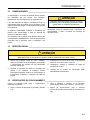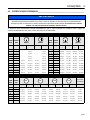
1
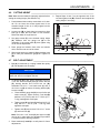
4131584-PT-Rev B
Dealer Manual
Manual do distribuidor
Greens King 500A Series
InCommand™
63281 – 18” 11 Blade Reel / Rolo de 11 lâminas de 457 mm
63287 – 18” 15 Blade Reel / Rolo de 15 lâminas de 457 mm
63282 – 22” 11 Blade Reel / Rolo de 11 lâminas de 559 mm
63288 – 22” 15 Blade Reel / Rolo de 15 lâminas de 559 mm
63285 – 26” 7 Blade Reel, Tee & Collar / Rolo de 7 lâminas de 660 mm, Tee e Colar
WARNING
WARNING: If incorrectly used this machine can cause severe
injury. Those who use and maintain this machine should be
trained in its proper use, warned of its dangers and should
read the entire manual before attempting to set up, operate,
adjust or service the machine.
AVISO
AVISO: Utilizada incorretamente, esta máquina pode
provocar ferimentos graves. Aqueles que utilizarem esta
máquina e fizerem a manutenção da mesma tęm de ter
formação para a sua utilização correta, tęm de ser informados
acerca dos perigos e devem ler todo o manual antes de tentar
configurar, trabalhar ou fazer a manutenção da máquina.
PT
Portugal
RJL 100 August 2014
When Performance Matters.™
CONTENTS
1
CONTENTS
1
SAFETY
1.1How to Operate Safely ............................................. 3
1.2 Important Safety Notes ........................................ 6
2
CONTROLS
2.1 Icons .................................................................... 7
2.2 Controls ............................................................... 7
3
SET UP
3.1 General ................................................................ 9
3.2 Initial inspection ................................................... 9
3.3
3.4
4
4.1
4.2
4.3
4.4
4.5
4.6
operating checks ................................................. 9
Operator Presence Control ................................ 10
ADJUSTMENTS
General.............................................................. 11
Reel-To-Bedknife ............................................... 11
Bedknife ............................................................. 12
Brake ................................................................. 12
Cutting Height .................................................... 13
Handle ............................................................... 13
Proposition 65 Warning
Engine exhaust from this product
contains chemicals known to the State
of California to cause cancer, birth
defects, and other reproductive harm
© Jacobsen, A Textron Company/Textron Innovations Inc.
“All rights reserved, including the right to reproduce this book or portions thereof in any form”.
All information in this publication is based on information available at time of approval for printing. Jacobsen reserves
the right to make changes at any time without notice and without incurring any obligation.
LITHO IN U.S.A 9-2014
2
SAFETY
1
1
SAFETY
1.1 HOW TO OPERATE SAFELY
! WARNING
EQUIPMENT OPERATED INCORRECTLY OR WITHOUT TRAINING CAN BE DANGEROUS.
Know the location and correct operation of controls. Operators without experience must receive instruction from
another person that knows the correct operation of the equipment before you operate the mower.
Only use parts, accessories and attachments approved by Jacobsen.
SAFE OPERATION
a
a
Read the Operator’s Manual and other training
material. If the operator or technician can not read
this manual, the owner is responsible to describe
this material to the operators and technicians.
Manuals in additional languages may be available
on the Jacobsen or RansomesJacobsen website.
Read all of the instructions for this mower carefully.
Know the controls and the correct operation of the
equipment.
b
Children or persons who do not understand these
instructions must not use the mower. The local
regulations can limit the age of the operator.
c
Never use a mower near persons, including
children or animals.
d
Remember that the operator or owner is
responsible for accidents or hazards that occur to
other persons or their property.
e
Never carry passengers.
f
Never allow persons to operate or service the
mower or its attachments without correct
instructions.
g
d
Inspect the mower before you operate the mower.
Check the tire pressure, engine oil level, the
radiator coolant level and the air cleaner indicator.
Fuel is flammable. Use caution when you add the
fuel to the mower.
e
Operate the mower in daylight or in good artificial
light. Use caution when you operate the mower
during bad weather. Never operate the mower with
lightning in the area.
f
Inspect the area to select the accessories and
attachments that are needed to correctly and safely
do the job. Only use parts, accessories and
attachments approved by Jacobsen.
g
Be careful of holes in the terrain and other hazards
that are not visible.
h
Inspect the area where the equipment is operated.
Remove all objects you can find before you
operate. Be careful of obstructions above the
ground (low tree limbs, electrical wires) and also
underground obstacles (sprinklers, pipes, tree
roots). Enter a new area carefully. Look for
possible hazards.
i
Inspect the cutting system before you start the
mower. Make sure the blades are free to rotate.
When you rotate one blade, other blades can
rotate.
Do not operate equipment while tired, sick or after
you use alcohol or drugs.
PREPARATION
OPERATION
a
When you operate the mower, wear correct
clothing, slip resistant work shoes or boots, work
gloves, hard hat, safety glasses and hearing
protection. Long hair, loose clothing or jewelry can
be caught in moving parts.
a
Never operate the engine without enough
ventilation or in an enclosed area. The carbon
monoxide in the exhaust fumes can increase to
dangerous levels.
b
Do not operate the equipment with the Interlock
System disconnected or the system does not
operate correctly. Do not disconnect or prevent the
operation of any switch.
b
Never carry passengers. Keep other persons or
animals away from the mower.
c
Disengage all drives and engage the parking brake
before you start the engine. Only start the engine
with the operator in the seat. Never start the engine
with persons near the mower.
c
Never operate equipment that is not in correct
order or without decals, guards, shields, deflectors
or other protective devices fastened.
3
1
SAFETY
d
Keep your legs, arms and body inside the operator
compartment while the mower is in operation.
Keep your hands and feet away from the cutting
units.
–
Stop the engine and remove the key.
p
e
Do not use on the slopes greater than the safe
slope limit for the equipment.
When you hit an object or mower starts to cause
the vibration that is not normal, inspect the mower
for damage and make repairs.
q
f
To guard against over turning or loss of control:
Decrease the throttle setting before you stop the
engine.
–
Operate the mower across the face (horizontally),
but not up and down on the face of slopes
(vertically).
r
Do not use this equipment for uses that the mower
was not made for.
SAFE HANDLING OF FUELS
–
Do not start or stop suddenly on slopes.
a
–
Decrease the speed when you operate on slopes
or when you must turn. Use caution when you
change direction. Turf condition can change the
mower stability.
The fuel and the fuel vapors are flammable. Use
caution when you add the fuel to the mower. The
fuel vapors can cause an explosion.
b
Never use the containers that are not approved to
keep or transfer fuel.
c
Never keep the mower or fuel containers near an
open flame or any device that can cause the
ignition of fuel or fuel vapors.
–
Use caution when you operate the mower near
drop-offs, ditches or embankments.
–
Be careful of holes in the terrain and other hazards
that are not visible.
d
g
Always operate at speeds that allow you to have
complete control of the machine. Make sure of your
footing keep a tight grip the handle and walk.
Never run when you operate the mower.
Never fill the fuel containers inside a vehicle or on
a truck or trailer with a plastic liner. Always put the
fuel container on the ground away from your
vehicle before you fill the container.
e
Refuel the mower before you start the engine.
When the engine is in operation or while the engine
is hot, never remove the fuel cap or add fuel to the
mower.
h
Use caution when you go near corners, trees or
other objects that can prevent a clear view.
i
Equipment must meet the current regulations to be
driven on the public roads.
f
Refuel outdoors only and do not smoke when you
add fuel. Extinguish all types of ignition.
j
Before you move across or operate on the paths or
roads, turn off the PTO switch, lift the mowers and
travel at decreased speed. Look for traffic.
g
The fuel nozzle must touch the rim of the fuel tank
when you add fuel to the mower. Do not use a
device to lock the fuel nozzle in the open position.
k
Stop the blades when the mower is on any surface
that is not grass.
h
Do not over fill the fuel tank. Leave at least 1 inch
(25 mm) below the filler neck.
l
Do not release the cut grass in the direction of
persons or allow persons near the mower while in
operation.
i
Always tighten the fuel tank cap and container cap
after you add fuel.
m
Do not operate the mower with damaged guards or
without safety devices in position.
j
If the fuel spills on your clothing, change your
clothing immediately.
n
Do not change the engine governor setting or overspeed the engine. Never change or tamper with
adjusters that are closed with a seal for the engine
speed control.
o
MAINTENANCE AND STORAGE
a
Before you leave the operator compartment, for
any reason:
Before you clean, adjust or repair this equipment,
stop the engine and disconnect the spark plug
wire. Keep the wire away from the plug to prevent
the engine to start.
b
–
Disengage all the drives and lower attachments to
the ground.
Make sure the mower is parked on a solid and level
surface.
c
–
Engage the parking brake.
Never work on a mower that is lifted only by the
jack. Always use the jack stands.
4
SAFETY
1
d
Never allow persons to service the mower or its
attachments without correct instructions.
WHEN YOU PUT THE MOWER ON A
TRAILER
e
When the mower is parked, put into storage or left
without an operator, lower the cutting device unless
a positive mechanical lock is used.
a
Be careful when you load or unload the mower on
a trailer. Trailer must be wider than the mower and
can carry the weight of the mower.
f
When you put the mower on a trailer or put the
mower in storage, close the fuel valve. Do not keep
fuel near flames or drain the fuel inside a building.
b
Use a full-width ramp to load or unload the mower
on a trailer.
g
Disconnect the battery before you service the
mower. Always disconnect the negative battery
cable before the positive battery cable. Always
connect the positive battery cable before the
negative battery cable.
c
Use straps, chains, cables or ropes to fasten the
mower to the trailer. Both front and rear straps
must be sent down and toward sides of trailer.
d
Make sure that all latches are correctly fastened.
h
Charge the battery in an area with good airflow.
The battery can release hydrogen gas that is
explosive. To prevent an explosion, keep any
device that can cause sparks or flames away from
the battery.
i
Disconnect the battery charger from the power
supply before you connect or disconnect the
battery charger to the battery. Wear protective
clothing and use insulated tools when you service
the battery.
j
Be careful and wear gloves when you check or
service the cutting unit blades. Replace any
damaged blades, do not try to correct a damaged
blade.
k
Keep your hands and feet away from parts that
move. Do not adjust the mower with the engine in
operation, unless the adjustment needs the engine
in operation.
l
Carefully release the pressure from components
with stored energy.
m
Keep the mower and the engine clean.
n
Allow the engine to become cool before storage
and always remove the ignition key.
o
Keep all nuts, bolts and screws tight to make sure
the equipment is in safe condition.
p
Replace worn or damaged parts for safety.
Replace damaged or worn decals. Only use parts,
accessories and attachments approved by
Jacobsen.
q
To decrease the fire hazard, remove materials that
burn from the engine, muffler, battery tray and fuel
tank area.
r
Disconnect the battery and controller connectors
before you weld on this mower.
5
1
1.2
SAFETY
IMPORTANT SAFETY NOTES________________________________________________
This safety alert symbol is used to alert you to potential hazards.
DANGER - Indicates an imminently hazardous situation which, if not avoided, WILL result in death or serious injury.
WARNING - Indicates a potentially hazardous situation which, if not avoided, COULD result in death or serious
injury.
CAUTION - Indicates a potentially hazardous situation which, if not avoided, MAY result in minor or moderate injury
and property damage. It may also be used to alert against unsafe practices.
NOTICE - Indicates a potentially hazardous situation which, if not avoided, MAY result in property damage. It may
also be used to alert against unsafe practices.
For pictorial clarity, some illustrations in this manual may show shields, guards or plates open or removed. Under no
circumstances should this equipment be operated without these devices securely fastened in place.
! WARNING
The Operator Presence Control (OPC) on this machine will shut off the reel
and traction drive if the operator releases the OPC bail.
To protect the operator and others from injury, never operate equipment with
the OPC system disconnected or malfunctioning.
! WARNING
1. Before leaving the operator’s position for any reason:
a. Disengage all drives.
b. Engage parking brake.
c. Stop engine.
2. Keep hands, feet, and clothing away from moving parts. Wait for all
movement to stop before you clean, adjust or service the machine.
3. Keep the area of operation clear of all bystanders and pets.
4. Chock or block the wheels if the machine is left on an incline.
5. Never operate mowing equipment without the discharge deflector
securely fastened in place.
By following all instructions in this manual, you will prolong the life of your machine and maintain its maximum
efficiency. Adjustments and maintenance should always be performed by a qualified technician.
If additional information or service is needed, contact your Authorized Jacobsen Dealer who is kept informed of the
latest methods to service this equipment and can provide prompt and efficient service.
6
CONTROLS
2
2.1
2
CONTROLS
ICONS ___________________________________________________________________
Fast
O.P.C. Unlock
Engine Off
O.P.C. Lock
Engine Run
Throttle
Slow
Parking Brake
Engaged Disengaged
Fuel
Gasoline
Choke
! WARNING
Never attempt to operate the machine unless you have read the Technical Manual and the
engine manual and know how to operate all controls correctly.
Familiarize yourself with the icons shown above and what they represent. Learn the
location and purpose of all the controls before operating this mower.
2.2
CONTROLS_______________________________________________________________
A. Parking Brake – Used whenever the mower is left
unattended or as a service brake while transporting.
B. Paddle Throttle – Controls the speed of the engine
when OPC Bail is engaged. Push (+) side of lever to
increase engine speed. Push (-) side of lever to
decrease engine speed.
C. O.P.C. Bail – Engaging bail increases engine speed
which engages the centrifugal clutch. Release bail
to return engine to idle. The bail must be
disengaged to start the engine.
D. Engine Switch – The engine switch enables and
disables the ignition system. The engine switch
must be in the ON position for the engine to run.
Turning the engine switch to the OFF position stops
the engine.
B
J
C
P
A
N
D
Figure 2A
D
OFF
ON
Figure 2B
7
2
CONTROLS
E. Choke Lever - The choke lever opens and closes
the choke valve in the carburetor. The CLOSED
position enriches the fuel mixture for starting a cold
engine. The OPEN position provides the correct fuel
mixture for operation after starting, and for restarting
a warm engine.
F.
Fuel Valve Lever - The fuel valve opens and closes
the connection between the fuel tank and the
carburetor. The fuel valve lever must be in the ON
position for the engine to run. When the engine is
not in use, leave the fuel valve lever in the OFF
position to prevent carburetor flooding and to reduce
the possibility of fuel leakage.
OFF
ON
E
F
Figure 2C
NOTICE
G
Before tipping mower back for adjustments, the fuel
lever must be moved to the OFF position to prevent
fuel from leaking into the crankcase.
G. Traction Clutch Lever - Point lever forward (G2) to
disengage traction drive and allow drum to “freewheel”. Point lever to the back (G1) to engage.
H. Reel Clutch Lever - Point lever up (H1) to engage
the reel drive mechanism. Point lever down (H2) to
disengage the reel.
! WARNING
To prevent bodily injury or property damage, never
engage the reel or traction clutch levers while the
engine is running or the O.P.C. bail is engaged.
! DANGER
Keep hands and feet away from the cutting unit to
prevent serious cuts.
J. E-Stop - Used to stop the engine. Push switch
down to disable engine ignition, pull up for normal
operation.
8
G1
G2
H1
H2
H
Figure 2D
SET UP
3
3.1
SET UP
GENERAL ________________________________________________________________
The set-up and testing of the unit should always be
performed by a trained technician, familiar with the
operation of the equipment.
Read each instruction completely and make sure you
understand it before proceeding with the assembly. Stay
alert for potential hazards and obey all safety
precautions.
The RIGHT, LEFT, FRONT and REAR of the machine are
referenced from the operator’s seat, facing forward.
3.2
3
Accessories not included with this product must be
ordered separately. See instructions provided with
accessory for installation and parts.
! CAUTION
Do not attempt to operate the machine unless you are
familiar with this type of equipment and know how to
operate all controls correctly.
This machine is shipped assembled. After unpacking,
perform the initial inspection, operating checks, and test
the Operator Presence Control (OPC).
INITIAL INSPECTION _______________________________________________________
! CAUTION
The initial inspection should be performed only when the engine is off and all fluids are cold.
Disengage all drives, engage parking brake, and stop engine.
1. Perform a visual inspection of the entire unit, look for
signs of wear, loose hardware, and components that
may have been damaged during transport.
2. Inspect paint and decals for damage or scratches.
Decals provide important operating and safety
information. Replace all missing or hard to read
decals.
3.3
3. Check that the engine oil level is at the full level
mark with the engine cold.
4. Visually check for fuel or oil leaks.
5. Inspect lube points for proper lubrication.
OPERATING CHECKS ______________________________________________________
After the initial inspection, test the machine for proper
operation.
2. Start the machine and check that controls operate
as described. See Section 3.2.
1. Test the Operator Presence Control. (Section 4.4)
3. After operation, stop and inspect again for fuel or oil
leaks.
9
3
3.4
SET UP
OPERATOR PRESENCE CONTROL (O.P.C.)____________________________________
1. The O.P.C. system is intended to protect the operator
and others from injury by stopping the reel and drive
mechanism as soon as the operator releases the
O.P.C. bail. The unit is also equipped with an engine
stop (E-Stop) switch that will stop the engine from the
operator’s position.
! WARNING
Never operate equipment with the O.P.C. system
disconnected or malfunctioning. Do not
disconnect or bypass any switch.
2. To test the system:
a. Place mower on the kickstand.
b. Disengage the reel clutch lever (E).
10
3. Start the engine.
a. Slide bail to the left adn engage OPC Bail.
b. Engine speed will increase, the drive mechanism
will engage and the wheels will begin to turn.
c.
Release the O.P.C. bail. The bail must
disengage, engine speed return to idle and drive
mechanism must stop.
d. Push E-Stop switch down. Engine must stop
immediately.
4. If the drive mechanism engages before the O.P.C.
bail is engaged or the drive mechanism continue to
turn after the O.P.C. bail is released; stop the engine
immediately and have the system repaired.
ADJUSTMENTS
4
4
ADJUSTMENTS
4.1
GENERAL ________________________________________________________________
! WARNING
Before you adjust, clean, or repair this equipment,
always disengage all drives, engage parking brake,
and stop engine to prevent serious injury.
Whenever performing maintenance other than
carburetor adjustments, remove the spark plug wire,
and place the wire away from the plug to prevent
accidental starting and bodily injury.
1. Adjustments and maintenance should always be
performed by a qualified technician. If proper
adjustment cannot be made, contact an authorized
Jacobsen dealer.
2. Replace, do
components.
not
adjust,
worn
or
damaged
3. Long hair, jewelry, or loose fitting clothing may get
tangled in moving parts.
! CAUTION
Be careful to prevent entrapment of the hands and
fingers between moving and fixed components of the
machine.
4. Do not change governor settings or overspeed the
engine.
4.2 REEL-TO-BEDKNIFE _______________________________________________________
6. Grass conditions will also affect the adjustment.
(Pre-adjustment Check)
1. Check the reel bearings for end play or radial play. If
there is any abnormal movement of the reel, up and
down or side to side, adjust or replace components
as needed.
! CAUTION
To prevent personal injury and damage to the cutting
edges, handle the reel with extreme care.
2. Inspect the reel blades and bedknife to ensure good
sharp edges without bends or nicks.
a. The cutting edges of the reel blades and bedknife must be sharp, free of burrs and show no
signs of rounding off.
b. The bedknife and bedknife backing must be
securely tightened. The bedknife must be
straight and sharp.
c. A flat surface of at least 1/32 in. (0.8 mm)
minimum must be maintained on the front face of
the bedknife. Use a standard flat file to dress the
bedknife.
a. Dry, sparse conditions will require a wider gap to
prevent heat buildup and damage to the reel and
bedknife.
b. High quality grass with a good moisture content
requires a closer gap (near zero).
°
°
1/32 in.
(0.8 mm)
Figure 4A
3. If wear or damage is beyond the point where the
reel or bedknife can be corrected by the lapping
process, they must be reground.
4. Proper reel-to-bedknife adjustment is critical. A gap
of 0.001 to 0.003 in. (0.025 to 0.076 mm) must be
maintained across the entire length of the reel and
bedknife.
5. The reel must be parallel to the bedknife. An
improperly adjusted reel will lose its sharp edges
prematurely and may result in serious damage to
the reel and bedknife.
11
4
4.3
ADJUSTMENTS
BEDKNIFE ADJUSTER _____________________________________________________
1. Adjuster (A) is used to increase or decrease the
spring load on the bedknife. Adjuster (B) is used to
move the bedknife to the reel or away from the reel.
A
B
2. Once the spring is totally collapsed as a result of
many adjustments, the bedknife cannot be moved.
Back-off adjuster (A) before adjusting (B).
3. For most applications, compress the spring to 1 in.
(25 mm).
Figure 4B
4.4
BEDKNIFE _______________________________________________________________
1. Read Section 5.2 before making the adjustment.
2. Start adjustment at the leading edge of the reel,
followed by the trailing end. The leading end of the
reel blade is the end that passes over the bedknife
first during normal rotation.
Rotation
Leading Edge
Figure 4C
3. Turn adjuster (B) clockwise to bring the bedknife
closer to the reel or counterclockwise to back the
bedknife away from the reel.
a. Slide a feeler gauge or shim stock 0.001 - 0.003
in., (0.025 - 0.075 mm) between the reel blade
and the bedknife. Do not turn the reel.
b. Adjust the trailing end of the reel in the same
manner, then recheck the adjustment at the
leading end.
c.
When the reel and bedknife are properly
adjusted, the reel will spin freely, and will cut a
piece of newspaper along the full length of the
reel when the paper is held at 90° to the
bedknife.
! CAUTION
To prevent personal injury and damage to the cutting
edges, handle the reel with extreme care.
4.5
BRAKE __________________________________________________________________
A properly adjusted brake requires 10 lb. pull at top of
brake lever to engage and must have 1.50 in. (38 mm)
center to center when released.
1. Minor adjustments are made at the handle. Loosen
nut (H), turn nut (J) to adjust the brake cable, then
tighten nut (H).
2. If adjustments cannot be made at the handle,
remove the transport wheel, and make the
adjustment at the brake band.
3. Loosen screw (K) and pull cable to obtain desired
brake tension. Tighten screw (K). Readjust (H) and
(J).
1.50 in.
(38 mm)
H
J
K
Brake Band
Figure 4D
12
ADJUSTMENTS
4.6
4
CUTTING HEIGHT _________________________________________________________
Note: Make sure the bedknife is properly adjusted before
setting the cutting height. (See Section 5.4)
1. Push kickstand down and tip mower back on it’s handle. Do not leave the mower tipped back for an
extended length of time or oil may migrate into the
combustion chamber.
6. Repeat Steps 4 and 5 on the opposite end of the
reel then tighten nuts (M). Recheck and readjust the
cutting height if necessary.
L
2. Loosen nuts (M) on both sides just enough to allow
knob (L) to raise the front roller or Turf Groomer.
Raise both sides an equal amount.
M
3. Set gauge screw (P) to the desired cutting height
(O). Measure from the gauge bar (N) to the
underside of the screw head (P) then tighten wing
nut to lock the adjustment.
4. Place gauge bar between front roller and traction
roller, near the outer end of the rollers.
N
4.7
Q
P
O
5. Slide screw head over bedknife (Q) and adjust knob
(L) so roller just contacts the gauge bar. Tighten nut
(M).
Figure 4E
BELT ADJUSTMENT _______________________________________________________
1. Belt (A) is tensioned by a spring loaded idler pulley
(F). No adjustment is necessary.
E
D
NOTICE
To prevent permanent damage to the belt, do not
twist, fold, bend or overtighten the belt.
F
2. To adjust belt (B) or (C), loosely assemble 5/16-18 x
3-1/4” hex head screw (K) through tension bracket
(P), bearing bracket and 5/16-18 hex nut (N).
Assemble 5/16-18 x 1” hex head screw (L) and 5/
16-18 hex nut (N) to bottom of bearing bracket (G).
Loosen nuts (E).
a.
B
C
Place bedknife gauge bar (H) on top of roller and
under screw (L). Tighten screw (L) until belt (B)
deflects 1/10” (2.5 mm) with 12.2 ~ 15.2 lb (5.5 ~
7.4 kg) load applied at mid span.
b. Tighten screw (K) until belt (C) deflects 9/64” (3.5
mm) with 3.5 ~ 6.3 lb (1.59 ~ 2.86 kg) load
applied at mid span.
c.
A
Tighten nuts (E) and remove 5/16-18 x 1” screw
(L) and lower nut (N).
N
K
G
F
M
L
H
Note: 5/16-18 x 3-1/4” screw (K) and upper nut (N)
can be left in place after the adjustment procedure
is complete without affecting operation.
3. Place hardware (L and N) in a safe place for future
adjustments.
Figure 4F
13
4
4.8
ADJUSTMENTS
HANDLE _________________________________________________________________
1. To adjust the angle of the handle bar (Y), loosen
screw (W) on both sides of the mower and adjust the
handle bar to the desired position.
2. After adjusting handle bar, adjust bracket (X) so that
the handle bar just rests on the bottom of the slot in
bracket. Tighten screw (W).
Y
X
W
Figure 4G
14
ADJUSTMENTS
4.9
4
TORQUE SPECIFICATION ___________________________________________________
NOTICE
All torque values included in these charts are approximate and are for reference only. Use of these torque values is
at your sole risk. Jacobsen is not responsible for any loss, claim, or damage arising from the use of these charts.
Extreme caution should always be used when using any torque value.
Jacobsen uses Grade 5 Plated bolts as standard, unless otherwise noted. For tightening plated bolts, use the value
given for lubricated.
AMERICAN NATIONAL STANDARD FASTENERS
SIZE
UNITS
GRADE 5
Lubricated
GRADE 8
Dry
Lubricated
SIZE
UNITS
GRADE 5
Dry
Lubri-
GRADE 8
Dry
Lubri-
cated
Dry
cated
#6-32
in-lb (Nm)
–
20 (2.3)
–
–
7/16-14
ft-lb (Nm)
37 (50.1)
50 (67.8)
53 (71.8)
70 (94.9)
#8-32
in-lb (Nm)
–
24 (2.7)
–
30 (3.4)
7/16-20
ft-lb (Nm)
42 (56.9)
55 (74.6)
59 (80.0)
78 (105)
#10-24
in-lb (Nm)
–
35 (4.0)
–
45 (5.1)
1/2-13
ft-lb (Nm)
57 (77.2)
75 (101)
80 (108)
107 (145)
#10-32
in-lb (Nm)
–
40 (4.5)
–
50 (5.7)
1/2-20
ft-lb (Nm)
64 (86.7)
85 (115)
90 (122)
120 (162)
#12-24
in-lb (Nm)
–
50 (5.7)
–
65 (7.3)
9/16-12
ft-lb (Nm)
82 (111)
109 (148)
115 (156)
154 (209)
1/4-20
in-lb (Nm)
75 (8.4)
100 (11.3)
107 (12.1)
143 (16.1)
9/16-18
ft-lb (Nm)
92 (124)
122 (165)
129 (174)
172 (233)
1/4-28
in-lb (Nm)
85 (9.6)
115 (13.0)
120 (13.5)
163 (18.4)
5/8-11
ft-lb (Nm)
113 (153)
151 (204)
159 (215)
211 (286)
5/16-18
in-lb (Nm)
157 (17.7)
210 (23.7)
220 (24.8)
305 (34.4)
5/8-18
ft-lb (Nm)
128 (173)
170 (230)
180 (244)
240 (325)
5/16-24
in-lb (Nm)
173 (19.5)
230 (26.0)
245 (27.6)
325 (36.7)
3/4-10
ft-lb (Nm)
200 (271)
266 (360)
282 (382)
376 (509)
3/8-16
ft-lb (Nm)
23 (31.1)
31 (42.0)
32 (43.3)
44 (59.6)
3/4-16
ft-lb (Nm)
223 (302)
298 404
315 (427)
420 (569)
3/8-24
ft-lb (Nm)
26 (35.2)
35 (47.4)
37 (50.1)
50 (67.8)
7/8-14
ft-lb (Nm)
355 (481)
473 (641)
500 (678)
668 (905)
METRIC FASTENERS
4.6
SIZE
8.8
10.9
Non Critical
Fasteners
into
Aluminum
12.9
UNITS
Lubricated
Dry
Lubricated
Dry
Lubricated
Dry
Lubricated
Dry
–
–
3.83 (34)
5.11 (45)
M4
Nm (in-lb)
–
–
–
–
2.0 (18)
M5
Nm (in-lb)
1.80 (16)
2.40 (21)
4.63 (41)
6.18 (54)
6.63 (59)
8.84 (78)
7.75 (68)
10.3 (910
4.0 (35)
M6
Nm (in-lb)
3.05 (27)
4.07 (36)
7.87 (69)
10.5 (93)
11.3 (102)
15.0 (133)
13.2 (117)
17.6 (156)
6.8 (60)
M8
Nm (in-lb)
7.41 (65)
9.98 (88)
19.1 (69)
25.5 (226)
27.3 (241)
36.5 (323)
32.0 (283)
42.6 (377)
17.0 (150)
M10
Nm (ft-lb)
14.7 (11)
19.6 (14)
37.8 (29)
50.5 (37)
54.1 (40)
72.2 (53)
63.3 (46)
84.4 (62)
33.9 (25)
M12
Nm (ft-lb)
25.6 (19)
34.1 (25)
66.0 (48)
88.0 (65)
94.5 (70)
125 (92)
110 (81)
147 (108)
61.0 (45)
M14
Nm (ft-lb)
40.8 (30)
54.3 (40)
105 (77)
140 (103)
150 (110)
200 (147)
175 (129)
234 (172)
94.9 (70)
15
5
5
16
NOTES
NOTES
Pre-Delivery Checklist
Product No. 63281, Greens King™518A Serial No. ____________________
Product No. 63282, Greens King™522A Serial No. ____________________
Product No. 63285, Greens King™526A Serial No. ____________________
Mower —————————————————
Cutting Units ———————————————
Check:
Check:
o
o
o
o
o
o
o
o
o
o
o
Brake adjustment
Handle bar angle & spring adjustment
Transport wheel installation & retaining clip function
Traction clutch operation
Reel clutch operation
Engine clutch operation & adjustment
Operation of kickstand
All decals in place and legible
Bedknife screws tight
Reel - should be no free end play
All hardware properly tightened
Adjust the following:
o
o
o
Reel to bedknife, .001” to .003” (.025 - .08 mm) clearance.
Bedknife backing adjuster spring tension
Adjust cutting height to customers’ requirements
OPC
Miscellaneous ——————————————
Belt Adjustments
Check:
Tire pressure 6 -8 psi (41 - 55 kPa) (with 62293 Option)
o
o
o
o
Engine —————————————————
Check:
o
o
o
o
o
Engine oil level
Air cleaner element and connections
For loose or missing hardware
All lubrication points
Paint finish; touch up where necessary
Decals in place and legible
o __________________________________________________
o __________________________________________________
Electrical System ————————————
o
Engine switch working correctly
Should you encounter any areas that required repair during set-up, please explain below and fax (704-504-4908) a copy of
the checklist and problem description to us.
Problem Description
_____________________________________________________________________________________________
_____________________________________________________________________________________________
_____________________________________________________________________________________________
Dealer ______________________________________________
Inspected ______________________________
Customer ___________________________________________
Date _________________________________
ÍNDICE
1
ÍNDICE
1
1.1
1.2
SEGURANÇA
Como utilizar com segurança ........................... 3
Instruções importantes de segurança .............. 6
2
2.1
2.2
COMANDOS
Ícones ............................................................... 7
Comandos ........................................................ 7
3
3.1
3.2
3.3
3.4
CONFIGURAÇÃO
Generalidades .................................................. 9
Inspeção inicial ................................................. 9
Verificações do funcionamento ........................ 9
Controlo de presença do operador (CPO) ...... 10
4
4.1
4.2
4.3
4.4
4.5
4.6
4.7
4.8
4.9
AFINAÇÕES
Generalidades ................................................ 11
Rolo de lâminas para lâmina fixa ................... 11
Regulador da lâmina fixa ................................ 12
Lâmina fixa ..................................................... 12
Travão ............................................................ 12
Altura de corte ................................................ 13
Afinação da correia ........................................ 13
Guiador ........................................................... 14
Especificação de binário ................................ 15
5
NOTAS
Aviso da Proposta 65
Este produto contém ou emite produtos
químicos reconhecidos pelo Estado da
Califórnia como a causa de cancro e
malformações congénitas ou de outros
perigos a nível da gestação.
© Jacobsen, A Textron Company/Textron Innovations Inc.
“Todos os direitos reservados, incluindo o direito de reproduzir este material ou porções de qualquer forma.”
Toda a informação nesta publicação é baseada na informação disponível na altura da aprovação para impressão. A
Jacobsen reserva-se o direito de fazer alterações a qualquer altura sem aviso e sem qualquer obrigação.
LITOGRAFADO NOS EUA 9-2014
pt-2
SEGURANÇA
1
1
SEGURANÇA
1.1 COMO UTILIZAR COM SEGURANÇA ______________________________________
! AVISO
EQUIPAMENTO UTILIZADO INCORRETAMENTE OU SEM FORMAÇÃO PODE SER PERIGOSO.
Conheça a localização e a operação correta dos comandos. Os operadores sem experiência devem receber
instruções de outra pessoa que conheça a operação correta do equipamento antes de utilizarem a máquina de
cortar relva.
Utilize apenas peças, acessórios e equipamentos complementares aprovados pela Jacobsen.
UTILIZAÇÃO SEGURA
a
Leia o Manual de utilização e outro material de
formação. Se o operador ou o técnico não
puderem ler este manual, o proprietário é
responsável por descrever este material aos
operadores e técnicos. Há manuais que podem
estar disponíveis noutros idiomas no sítio Web da
Jacobsen ou Ransomes Jacobsen.
a
Leia atentamente todas as instruções relativas a
esta máquina de cortar relva. Conheça os
comandos e a operação correta do equipamento.
b
As crianças ou pessoas que não compreendem
estas instruções não devem utilizar a máquina de
cortar relva. Os regulamentos locais podem limitar
a idade do operador.
c
Nunca utilize uma máquina de cortar relva perto de
pessoas, incluindo crianças ou animais.
d
Lembre-se de que o operador ou proprietário é o
responsável por acidentes ou situações de perigo
que ocorrem para outras pessoas ou na sua
propriedade.
e
Nunca transporte passageiros.
f
Nunca permita que pessoas operem ou façam a
manutenção da máquina de cortar relva sem as
instruções corretas.
g
Não opere o equipamento enquanto estiver
cansado, doente ou depois de usar álcool ou
drogas.
d
Inspecione a máquina de cortar relva antes de
operar a mesma. Verifique a pressão dos pneus, o
nível do óleo do motor, o nível do líquido de
arrefecimento do radiador e o indicador do filtro de
ar. O combustível é inflamável. Tenha cuidado ao
adicionar o combustível à máquina de cortar relva.
e
Conduza a máquina de cortar relva à luz do dia ou
com boa iluminação artificial. Tenha cuidado ao
operar a máquina de cortar relva com mau tempo.
Nunca opere a máquina de cortar relva com
relâmpagos na área.
f
Inspecione a área para selecionar os acessórios e
equipamento suplementar que são necessários
para realizar o trabalho corretamente e com
segurança. Utilize apenas peças, acessórios e
equipamentos complementares aprovados pela
Jacobsen.
g
Tenha cuidado com os buracos no terreno e com
outros perigos que não são visíveis.
h
Inspecione a área em que o equipamento é
operado. Retire todos os objetos que conseguir
encontrar antes de operar. Tenha cuidado com os
obstáculos acima do solo (ramos de árvores a
pouca altura, cabos elétricos) e também com os
obstáculos no subsolo (aspersores, tubos, raízes
de árvores). Entre cuidadosamente numa zona
nova. Observe se há possíveis perigos.
i
Inspecione o sistema de corte antes de ligar a
máquina de cortar relva. Certifique-se de que as
lâminas estão livres para rodar. Ao rodar uma
lâmina, há outras lâminas que podem rodar.
PREPARAÇÃO
a
Ao operar a máquina de cortar relva, use vestuário
adequado, calçado ou botas de trabalho
antiderrapantes, luvas de trabalho, capacete,
óculos de segurança e proteção auditiva. Peças
em movimento podem apanhar cabelo comprido,
vestuário largo e adereços.
b
Não opere o equipamento com o Sistema de
bloqueio desligado ou se o sistema não estiver a
funcionar corretamente. Não desligue ou evite a
operação de qualquer interruptor.
c
Nunca trabalhe com equipamento que não se
encontre em perfeito estado de funcionamento ou
que esteja sem sinalética, resguardos, painéis,
defletores ou outros dispositivos de proteção
instalados. Ao cortar a relva com um convés de
descarga lateral, NÃO opere a unidade de corte
sem a calha de descarga instalada.
FUNCIONAMENTO
a
Nunca opere o motor sem que haja ventilação
suficiente ou numa área fechada. O monóxido de
carbono nos gases de escape pode atingir níveis
perigosos.
b
Nunca transporte passageiros. Mantenha outras
pessoas ou animais afastados da máquina de
cortar relva.
c
Desengate todos os acionamentos e puxe o travão
de estacionamento antes de ligar o motor. Só ligue
o motor com o operador no banco. Nunca ligue o
motor com pessoas perto da máquina de cortar
relva.
d
Mantenha as pernas, os braços e o corpo no
interior da cabina enquanto a máquina de cortar
relva estiver em operação. Mantenha as mãos e os
pés afastados das unidades de corte.
pt-3
1
SEGURANÇA
e
Não utilize a máquina em taludes de inclinação
superior ao limite de segurança em taludes para o
equipamento.
f
Para precaver-se contra capotamento ou perda de
controlo:
–
Em taludes e declives, conduza a máquina de
cortar relva para cima e para baixo (verticalmente),
mas não na horizontal.
–
Não arranque nem pare bruscamente em taludes.
–
Reduza a velocidade ao operar em taludes ou
quando tiver de virar. Cuidado ao mudar de
direção. O estado da relva pode afetar a
estabilidade da máquina de cortar relva.
q
Diminua a regulação da borboleta antes de parar o
motor.
r
Não utilize este equipamento para fins a que a
máquina de cortar relva não se destina.
ROPS
a
O sistema ROPS é um dispositivo de segurança.
Mantenha o ROPS na posição vertical e
bloqueada. Utilize sempre o cinto de segurança ao
operar a máquina de cortar relva. Certifique-se de
que o cinto de segurança pode ser libertado
rapidamente em caso de emergência.
b
Só opere a máquina de cortar relva com o ROPS
na posição rebatida em superfícies planas e
niveladas quando necessário. Não opere a
máquina de cortar relva com o ROPS na posição
rebatida em taludes, perto de extremidades
afiadas e perto de água. Não há proteção contra
capotamento com o ROPS na posição rebatida.
c
Calcule a distância antes de conduzir por baixo de
objetos. Não entre em contacto com ramos de
árvores, cabos elétricos ou outros objetos com o
ROPS.
–
Tenha cuidado ao operar a máquina de cortar relva
perto de desníveis bruscos, valas ou aterros.
–
Tenha cuidado com os buracos no terreno e com
outros perigos que não são visíveis.
g
Ao conduzir em inversão de marcha, olhe para trás
e para baixo para certificar-se de que o caminho
está livre. Não opere as unidades de corte ao
conduzir em inversão de marcha.
h
Tenha cuidado ao aproximar-se de cantos, árvores
ou outros objetos que podem impedir uma
visibilidade clara.
d
Não utilize o cinto de segurança com o ROPS na
posição rebatida.
e
i
O equipamento deve cumprir os regulamentos
atuais para ser conduzido na via pública.
Inspecione o sistema ROPS para verificar se há
danos. Mantenha as peças do ROPS instaladas.
f
j
Antes de deslocar ou operar a máquina em
caminhos ou estradas, desligue o interruptor PTO,
levante as unidades de corte e circule a velocidade
reduzida. Observe se há trânsito.
Não solde, fure, altere nem dobre o ROPS.
Substitua um ROPS danificado. Não tente corrigir
um ROPS danificado.
g
Não retire o ROPS da máquina de cortar relva.
Pare as lâminas quando a máquina de cortar relva
estiver em qualquer superfície que não seja
relvada.
h
A Jacobsen deve aprovar todas as alterações ao
ROPS.
MANUSEAMENTO SEGURO DE COMBUSTÍVEIS
k
l
Não liberte a relva cortada na direção das pessoas
nem permita a presença de pessoas perto da
máquina de cortar relva enquanto esta estiver em
funcionamento.
m
Não utilize a máquina de cortar relva com
resguardos danificados ou sem os dispositivos de
segurança em posição.
n
Não altere a afinação do regulador do motor nem
aplique velocidade excessiva ao motor. Nunca
mude nem manipule adaptadores que estejam
fechados com um selo para controlar a velocidade
do motor.
o
Antes de sair da cabina por qualquer motivo:
–
Desengate todos os acionamentos e desça os
equipamentos suplementares até ao solo.
–
Engate o travão de estacionamento.
–
Desligue o motor e retire a chave da ignição.
p
Quando bater num objeto ou se a máquina de
cortar relva começar a vibrar anormalmente,
inspecione a máquina de cortar relva para verificar
se há danos e fazer reparações.
pt-4
a
O combustível e os vapores do combustível são
inflamáveis. Tenha cuidado ao adicionar o
combustível à máquina de cortar relva. Os vapores
do combustível podem provocar uma explosão.
b
Nunca utilize os recipientes não aprovados para
guardar ou transferir combustível.
c
Nunca guarde a máquina de cortar relva ou os
recipientes de combustível perto de chamas ou
qualquer dispositivo que possa provocar a ignição
do combustível ou vapores do combustível.
d
Não encha os recipientes de combustível num
veículo, camião ou reboque com revestimento
plástico. Coloque sempre o recipiente de
combustível no solo afastado do seu veículo antes
de encher o recipiente.
e
Reabasteça a máquina de cortar relva antes de
arrancar o motor. Quando o motor estiver em
operação ou enquanto o motor estiver quente,
nunca retire o tampão do depósito nem adicione
combustível à máquina de cortar relva.
f
Reabasteça sempre ao ar livre e não fume quando
estiver a adicionar combustível. Extinga todos os
tipos de ignição.
SEGURANÇA
1
g
O bocal de combustível deve tocar na jante do
depósito de combustível ao adicionar combustível
à máquina de cortar relva. Não utilize um
dispositivo para bloquear o bocal de combustível
na posição aberta.
k
Mantenha as mãos e os pés longe de peças que
se movem. Não regule a máquina de cortar relva
com o motor em funcionamento, a não ser que a
regulação exija que o motor esteja em
funcionamento.
h
Não encha demasiado o depósito de combustível.
Deixe pelo menos 25 mm abaixo do bocal de
enchimento.
l
Liberte
cuidadosamente
a
pressão
componentes com energia armazenada.
i
Aperte sempre a tampa do depósito de
combustível e a tampa do recipiente depois de
adicionar combustível.
m
Para evitar lesões provocadas por óleo quente a
alta pressão, nunca use as mãos para verificar
fugas de óleo. Utilize papel ou cartão para
encontrar fugas.
j
Se derramar combustível no vestuário, mude de
roupa imediatamente.
n
A pressão do líquido hidráulico pode ter força
suficiente para penetrar na pele. Se ocorrer
penetração do líquido hidráulico na sua pele, um
médico deverá remover cirurgicamente o líquido
hidráulico no espaço de algumas horas ou poderá
ocorrer gangrena.
o
Ao fazer a manutenção do sistema hidráulico,
certifique-se de que os encaixes hidráulicos, tubos
e mangueiras estão apertados com o binário
correto. Certifique-se de que o sistema hidráulico
se encontra em bom estado antes de arrancar o
motor.
p
Mantenha limpos a máquina de cortar relva e o
motor.
q
Deixe o motor arrefecer antes do armazenamento
e retire sempre a chave da ignição.
r
Mantenha todas as porcas, pernos e parafusos
apertados para garantir que o equipamento se
encontra em condições seguras.
s
Substitua peças gastas ou danificadas por motivos
de segurança. Substitua sinalética gasta ou
danificada. Utilize apenas peças, acessórios e
equipamentos complementares aprovados pela
Jacobsen.
t
Para reduzir o perigo de incêndio, retire os
materiais que queimam da área do motor,
silenciador, tabuleiro das baterias e depósito de
combustível.
u
Desligue os conectores da bateria e do controlador
antes de soldar nesta máquina de cortar relva.
MANUTENÇÃO E ARMAZENAMENTO
a
Antes de limpar, regular ou reparar este
equipamento, coloque o interruptor PTO na
posição OFF, desça a unidade de corte até ao
solo, engate o travão de estacionamento, pare o
motor e retire a chave da ignição.
b
Certifique-se de que a máquina de cortar relva
está estacionada numa superfície sólida e plana.
c
Nunca realize trabalhos numa máquina de cortar
relva que esteja levantada apenas pelo macaco.
Utilize sempre os suportes para o macaco.
d
Nunca permita que pessoas operem ou façam a
manutenção da máquina de cortar relva ou dos
respetivos equipamentos suplementares sem as
instruções corretas.
e
Quando a máquina de cortar relva é estacionada,
armazenada ou deixada sem um operador, desça
o dispositivo de corte, a não ser que seja utilizado
um bloqueio mecânico positivo.
f
Ao colocar a máquina de cortar relva num reboque
ou ao armazenar a máquina de cortar relva, feche
a válvula de combustível. Não guarde combustível
perto de chamas nem drene o combustível dentro
de um edifício.
g
Desligue a bateria antes de fazer a manutenção da
máquina de cortar relva. Desligue sempre o cabo
negativo da bateria antes de desligar o cabo
positivo da bateria. Ligue sempre o cabo positivo
da bateria antes de ligar o cabo negativo da
bateria.
h
Carregue a bateria numa área com boa circulação
do ar. A bateria pode libertar hidrogénio que é um
gás explosivo. Para evitar explosão, mantenha
chamas afastadas da bateria.
i
Desligue o carregador da bateria da alimentação
antes de ligar ou desligar o carregador da bateria à
bateria.
Use vestuário de proteção e utilize
ferramentas isoladas ao fazer a manutenção da
bateria.
Tenha cuidado e use luvas ao verificar ou fazer a
manutenção das lâminas da unidade de corte.
Substitua as lâminas danificadas. Não tente
consertar uma lâmina danificada.
j
dos
AO COLOCAR UMA MÁQUINA DE CORTAR RELVA NUM
REBOQUE
a
Tenha cuidado ao carregar ou descarregar a
máquina de cortar relva de um reboque. O
reboque deve ser mais largo do que a máquina de
cortar relva e poder transportar o peso da máquina
de cortar relva.
b
Utilize uma rampa de largura completa para
carregar ou descarregar a máquina de cortar relva
de um reboque.
c
Utilize faixas, correntes, cabos ou cordas para fixar
a máquina de cortar relva ao reboque. As faixas
dianteiras e traseiras devem passar por baixo e
pelos lados do reboque.
d
Certifique-se de que todas as linguetas estão
corretamente apertadas.
pt-5
1
1.2
SEGURANÇA
INSTRUÇÕES IMPORTANTES DE SEGURANÇA ________________________________
Este símbolo de segurança chama a atenção para possíveis perigos.
PERIGO:
Indica uma condição perigosa que CAUSARÁ morte ou lesão, a não ser que seja evitada.
AVISO:
Indica uma condição perigosa que PODE causar morte ou lesão, a não ser que seja evitada.
ATENÇÃO:
Indica uma condição perigosa que pode causar lesão ou danos materiais, a não ser que seja evitada. A sinalética pode
indicar também procedimentos de trabalho que não são seguros.
IMPORTANTE:
Só conduza a máquina à velocidade de estrada sempre que estiver numa via pública. Não deve selecionar velocidade
de estrada em zonas com relva, estradas acidentadas ou caminhos com cascalho.
Algumas ilustrações neste manual podem mostrar blindagens, proteções ou placas retiradas para limpeza. Este
equipamento não deve ser utilizado sem estes dispositivos corretamente colocados no lugar adequado.
AVISO
O sistema de bloqueio desta máquina de cortar relva evita o arranque da máquina, a não ser que a.) O travão de
estacionamento esteja engatado. b.) O interruptor de corte se encontre na posição OFF (DESLIGADO) e c.) O
pedal de tração esteja em ponto morto. d) O operador esteja sentado no banco. O sistema para o motor quando o
operador sai do banco a.) sem engatar o travão de estacionamento ou b.) o interruptor de corte não está na posição
OFF. NUNCA opere a máquina de cortar relva, exceto se o sistema de bloqueio estiver a funcionar.
AVISO
1. Se, por qualquer razão, tiver de sair do posto de condução:
a.
b.
c.
d.
e.
Coloque o pedal de tração na posição neutra.
Desengate todos os acionamentos.
Desça todos os dispositivos até ao chão.
Engate o travão de estacionamento.
Desligue o motor e retire a chave da ignição.
2. Mantenha as mãos, os pés e o vestuário longe de peças móveis. Espere que todos os movimentos parem
antes de limpar, afinar ou fazer a manutenção da máquina.
3. Mantenha a área de trabalho livre de todas as pessoas e animais.
4. Nunca transporte passageiros.
5. Nunca utilize o equipamento sem fixar corretamente um defletor de relva em posição.
Se seguir todas as instruções deste manual, prolongará a vida da sua máquina e manterá o seu rendimento máximo.
Operações de afinação e de manutenção só devem ser executadas por um técnico qualificado.
Se precisar de informação ou assistência adicional, deverá entrar em contacto com o seu vendedor autorizado de
Jacobsen, que está informado sobre os métodos de assistência mais recentes a este equipamento e pode prestar
assistência rápida e eficaz. A utilização de peças e acessórios que não sejam originais ou autorizadas pela
Jacobsen anularão a garantia.
pt-6
COMANDOS
2
2.1
2
COMANDOS
ÍCONES __________________________________________________________________
Travão de estacionamento
Engatado Desengatado
Desbloqueio do CPO
Motor desligado
Bloqueio do CPO
Motor em funcionamento
Acelerador (borboleta)
Rápido
Lento
Combustível
Gasolina
Estrangulamento
! AVISO
Nunca tente utilizar a máquina antes de ter lido o Manual técnico e o Manual do motor e de
saber como controlar corretamente todos os comandos.
Comece por familiarizar-se com os ícones apresentados acima e com o que estes
representam. Aprenda a localização e a finalidade de todos os comandos e indicadores
antes de trabalhar com este corta-relva.
2.2
COMANDOS ______________________________________________________________
A. Travão de estacionamento – Usar sempre que o
corta-relva seja deixado sem vigilância ou como
travão de serviço durante o transporte.
B
B. Acelerador das pás – Controla a velocidade do
motor quando a alavanca do CPO está engatada.
Empurre o lado (+) da alavanca para aumentar a
velocidade do motor. Empurre o lado (-) da
alavanca para diminuir a velocidade do motor.
C. Alavanca do CPO – Ao engatar a alavanca
aumentará a velocidade do motor que, por sua vez,
engata a embraiagem centrífuga. Liberte a alavanca
para libertar o motor. A alavanca deve ser
desengatada para ligar o motor.
D. Interruptor do motor – O interruptor do motor ativa
e desativa o sistema de ignição. O interruptor do
motor tem de se encontrar na posição ON (Ligado)
para o motor poder arrancar. Girar o interruptor do
motor para a posição OFF (Desligado) permite
parar o motor.
J
C
P
A
N
D
Figura 2A
D
OFF
ON
Figura 2B
pt-7
2
COMANDOS
E. Alavanca de estrangulamento – Esta alavanca
abre e fecha a válvula de estrangulamento do
carburador. Na posição CLOSED (Fechada), a
mistura de combustível é enriquecida para o
arranque do motor frio. A posição OPEN (Aberta)
assegura a mistura correta de combustível para o
motor trabalhar depois de arrancar e para voltar a
arrancar a quente.
Alavanca da válvula de combustível – A válvula
de combustível abre a ligação entre o depósito de
combustível e o carburador. A alavanca da válvula
de combustível tem de se encontrar na posição ON
(Ligado) para que o motor trabalhe. Quando o
motor estiver parado, deixe a alavanca da válvula
de combustível na posição OFF (Desligado) para
evitar que o carburador encharque e também para
reduzir o risco de fuga de combustível.
F.
ON
OFF
E
F
Figura 2C
G
G1
IMPORTANTE
Antes de virar o corta-relva para trás para afinações,
a alavanca do combustível deve ser movida para a
posição OFF (Desligado) para evitar fugas de
combustível no cárter.
G. Alavanca da embraiagem da tração – Empurre a
alavanca para a frente (G2) para desengatar o
acionamento da tração e para o tambor ficar em
"roda livre". Empurre a alavanca para trás (G1) para
engatar.
H. Alavanca da embraiagem do rolo de lâminas –
Puxe a alavanca para cima (H1) para engatar o
mecanismo de acionamento do rolo de lâminas.
Empurre a alavanca para baixo (H2) para
desengatar o rolo de lâminas.
! AVISO
Para evitar lesões corporais ou danos materiais,
nunca engate as alavancas do rolo de lâminas ou da
embraiagem da tração enquanto o motor estiver a
trabalhar ou se a alavanca do CPO estiver engatada.
! PERIGO
Para evitar cortes graves, mantenha as mãos e os
pés afastados da unidade de corte.
J. E-Stop – Utilizado para parar o motor. Carregue no
interruptor para parar o motor, puxe para cima para
a utilização normal do motor.
pt-8
G2
H1
H2
H
Figura 2D
CONFIGURAÇÃO
3
3.1
3
CONFIGURAÇÃO
GENERALIDADES _________________________________________________________
A configuração e os testes da unidade devem sempre
ser realizados por um técnico com formação,
familiarizado com o funcionamento do equipamento.
Leia cada instrução na íntegra e certifique-se de que a
compreende antes de continuar com a montagem. Fique
atento a potenciais perigos e cumpra todas a precauções
de segurança.
A DIREITA, ESQUERDA, FRENTE e TRASEIRA da
máquina são referenciadas a partir do assento do
operador virado para a frente.
! ATENÇÃO
Não tente operar a máquina a menos que esteja
familiarizado com este tipo de equipamento e saiba
operar todos os comandos corretamente.
Esta máquina é enviada montada. Depois de
desembalar, efetue a inspeção inicial, verificações de
funcionamento, e teste o Controlo de presença do
operador (CPO).
Os acessórios não incluídos neste produto devem ser
encomendados separadamente. Consulte as instruções
fornecidas com o acessório sobre a instalação e as
peças.
3.2
INSPEÇÃO INICIAL ________________________________________________________
! ATENÇÃO
A inspeção inicial deve ser realizada apenas quando o motor está desligado e todos os fluidos frios.
Desengate todos os acionamentos, engate o travão de estacionamento e pare o motor.
1. Efetue uma inspeção visual de toda a unidade,
verifique se existem sinais de desgaste, peças soltas
e componentes que possam ter sido danificados
durante o transporte.
2. Verifique a existência de danos ou arranhões na
pintura e na sinalética. A sinalética fornece
informação importante relativa ao funcionamento e
à segurança. Substitua a sinalética em falta ou
ilegível.
3.3
3. Verifique se o nível do óleo do motor se encontra na
marca de nível cheio com o motor frio.
4. Visualmente, verifique a existência de fugas de
combustível ou óleo.
5. Verifique se os pontos de lubrificação estão
adequadamente lubrificados.
VERIFICAÇÕES DO FUNCIONAMENTO ________________________________________
Depois da inspeção inicial, teste o funcionamento
adequado da máquina.
2. Ligue a máquina e verifique se os controlos
funcionam de acordo com o descrito. (Secção 3.2)
1. Teste o Controlo de presença do operador. (Secção
4.4)
3. Depois do funcionamento, pare e verifique
novamente a existência de fugas de combustível ou
óleo.
pt-9
3
CONFIGURAÇÃO
3.4
CONTROLO DE PRESENÇA DO OPERADOR (CPO) _____________________________
1. O sistema CPO tem a função de proteger o operador
e outras pessoas de lesões provocadas pela
paragem do rolo de lâminas e mecanismo do
acionamento assim que o operador liberta a
alavanca do CPO. A unidade também está equipada
com um interruptor para paragem do motor (E-Stop)
que parará o motor a partir da posição do operador.
3. Ligue o motor.
a. Deslize a alavanca para a esquerda e engate a
alavanca do CPO.
b. A velocidade do motor aumenta, o mecanismo
do acionamento engata e as rodas começam a
girar.
c.
! AVISO
Nunca utilize o equipamento com o sistema CPO
desligado ou avariado. Não desligue nem faça ponte
sobre qualquer interruptor.
2. Para testar o sistema:
a. Coloque o corta-relva no descanso.
b. Desengate a alavanca da embraiagem do rolo
de lâminas (E).
pt-10
Liberte a alavanca do CPO. A alavanca deve
desengatar, a velocidade do motor volta a
libertar-se e o mecanismo do acionamento deve
parar.
d. Carregue no interruptor E-Stop. O motor deve
parar imediatamente.
4. Se o mecanismo do acionamento engatar antes da
alavanca do CPO estar engatada, ou o mecanismo
do acionamento continuar a girar depois da
alavanca ter sido libertada; pare o motor
imediatamente e proceda à reparação do sistema.
AFINAÇÕES
4
4
AFINAÇÕES
4.1
GENERALIDADES _________________________________________________________
! AVISO
Antes de afinar, limpar ou reparar este equipamento,
desengate sempre todos os acionamentos, engate o
travão de estacionamento e desligue o motor para
evitar lesões graves.
Sempre que realizar ações de manutenção além das
afinações do carburador, desligue o cabo da vela de
ignição e coloque-o longe da vela para evitar um
arranque acidental e lesões corporais.
1. As afinações e os trabalhos de manutenção devem
ser sempre realizados por técnicos qualificados. Se
não for possível afinar corretamente, entre em
contacto com
Jacobsen.
um
distribuidor
autorizado
da
2. Componentes gastos ou danificados devem ser
substituídos e não afinados.
3. Cabelo comprido, joias ou vestuário largo podem
ser apanhados pelas peças móveis.
! ATENÇÃO
Tenha cuidado para evitar que mãos e dedos fiquem
presos entre os componentes móveis e fixos da
máquina..
4. Não altere os parâmetros do regulador de
velocidade nem exceda o limite do regime do motor.
4.2 ROLO DE LÂMINAS PARA LÂMINA FIXA ______________________________________
5. O rolo de lâminas deve estar paralelo à lâmina fixa.
(Verificação de pré-afinação)
1. Verifique os rolamentos do rolo de lâminas em
relação à folga na extremidade ou à folga radial. Se
o rolo de lâminas tiver um movimento anormal, quer
na vertical, quer lateralmente, afine ou substitua as
peças conforme necessário.
! ATENÇÃO
Para evitar lesões pessoais e danos nas
extremidades de corte, manuseie o rolo de lâminas
com cuidado extremo.
2. Inspecione as lâminas do rolo e a lâmina fixa para
certificar-se de que estão afiadas e não há
empenamentos ou danos.
a. As extremidades de corte das lâminas do rolo e
da lâmina fixa devem estar afiadas, livres de
rebarbas e não apresentar sinais de
abaulamento.
b. A lâmina fixa e o apoio da lâmina fixa devem
estar bem apertados. A lâmina fixa deve estar
retilínea e afiada.
c. Uma superfície plana de pelo menos 0,8 mm no
mínimo deve ser mantida na face frontal da
lâmina fixa. Utilize uma lima chata padrão para
aparelhar a lâmina fixa.
Um rolo de lâminas mal afinado perderá
prematuramente o afiamento e poderá provocar
sérios danos no rolo de lâminas e na lâmina fixa.
6. As condições da relva também afetarão a afinação.
a. A relva seca e escassa exigirá um espaço maior
para evitar a acumulação de calor e danos no
rolo de lâminas e na lâmina fixa.
b. A relva de alta qualidade com um bom teor de
humidade requer um intervalo menor (de quase
zero).
°
°
0,8 mm
(1/32 pol.)
Figura 4A
3. Caso o desgaste ou os danos do rolo de lâminas ou
da lâmina fixa já não possam ser corrigidos por
polimento, deve recorrer-se ao afiamento.
4. A afinação adequada entre o rolo de lâminas e a
lâmina fixa é um aspecto crítico. Deve ser mantido
um intervalo de 0,025 a 0,076 mm em todo o
comprimento do rolo de lâminas e da lâmina fixa.
pt-11
4
4.3
AFINAÇÕES
REGULADOR DA LÂMINA FIXA______________________________________________
1. O regulador (A) é usado para aumentar ou reduzir a
carga da mola sobre a lâmina fixa. O regulador (B) é
usado para aproximar ou afastar a lâmina fixa do rolo
de lâminas.
A
B
2. Depois da mola estar totalmente encolhida em
resultado de muitas regulações, a lâmina fixa deixa
de poder mover-se. Afaste o regulador (A) antes de
regular (B).
3. Para a maior parte das utilizações, comprima a
mola para 25 mm.
4.4
Figura 4B
LÂMINA FIXA ____________________________________________________________
1. Leia o Section 6.2 antes de proceder à regulação.
2. Inicie a regulação na extremidade inicial do rolo de
lâminas e, em seguida, na extremidade final. A
extremidade inicial das lâminas do rolo é a que
passa primeiro sobre a lâmina fixa durante a
rotação normal do rolo de lâminas.
Rotação
Extremidade principal
Figura 4C
! ATENÇÃO
3. Rode o regulador (B) para a direita para colocar a
lâmina fixa mais próxima do rolo de lâminas ou para
a esquerda para afastar a lâmina fixa do rolo de
lâminas.
a. Deslize um calibre de lâminas ou uma cunha de
0,025 – 0,075 mm entre a lâmina do rolo e a
lâmina fixa. Não rode o rolo de lâminas.
b. Regule a extremidade final do rolo de lâminas da
mesma forma e volte a verificar a regulação da
extremidade inicial.
c.
Quando
o
rolo
de
lâminas
estiver
adequadamente regulado com a lâmina fixa, o
rolo de lâminas girará livremente e poderá cortar
um pedaço de folha de jornal, ao longo da
extensão completa do rolo de lâminas, ao
colocar o papel a 90º em relação à lâmina fixa.
Para evitar lesões pessoais e danos nas
extremidades de corte, manuseie o rolo de lâminas
com cuidado extremo.
4.5
TRAVÃO _________________________________________________________________
Se o travão estiver corretamente afinado, será
necessária uma força de aproximadamente 4,5 kg para
puxar a extremidade da alavanca do travão para o
engatar e deve existir uma distância de 38 mm entre
centros quando solto.
1. Afinações pequenas são feitas no guiador. Solte a
porca (H) e rode-a (J) para afinar o cabo do travão
e, em seguida, aperte a porca (H).
2. Se não for possível fazer afinações no guiador,
desmonte a roda de transporte e proceda à
afinação na cinta do travão.
3. Solte o parafuso (K) e puxe o cabo para obter a
tensão pretendida para o travão. Aperte o parafuso
(K). Reajuste (H) e (J).
38 mm
(1,50 pol.)
H
J
K
Cinta do travão
Figura 4D
pt-12
AFINAÇÕES
4.6
4
ALTURA DE CORTE________________________________________________________
Nota: Certifique-se de que a lâmina fixa está
corretamente regulada antes de regular a altura de corte.
(Ver a Secção 6.4)
1. Empurre o descanso para baixo e incline o cortarelva para trás, para o guiador. Não deixe o cortarelva tombado para trás durante muito tempo porque
o óleo pode passar para a câmara de combustão.
6. Repita os passos 4 e 5 na outra extremidade do
rolo de lâminas e, em seguida, aperte as porcas
(M). Volte a verificar e a regular a altura de corte, se
necessário.
L
2. Solte as porcas (M) em ambos os lados, mas
apenas o suficiente para que o manípulo (L)
permita a subida do rolo dianteiro ou do tratador de
relva. Suba a mesma distância em ambos os lados.
M
3. Regule o parafuso padrão (P) para a altura de corte
desejada (O). Meça a distância entre a barra
padrão (N) e a parte de baixo da cabeça do
parafuso (P) e, em seguida, aperte a porca de
orelhas para fixar a regulação.
4. Coloque a barra padrão entre o rolo dianteiro e o
rolo de tração, perto da extremidade exterior dos
rolos.
N
Q
P
O
5. Deslize a cabeça do parafuso por cima da lâmina
fixa (Q) e regule o manípulo (L) de forma a que o
rolo toque apenas na barra padrão. Aperte a porca
(M).
4.7
Figura 4E
AFINAÇÃO DA CORREIA ___________________________________________________
1. A correia (A) é mantida sob tensão por um rolete
superior acionado por mola (F). Não é necessária
qualquer afinação.
3. Coloque as peças (L e N) em local seguro para
afinações futuras.
E
IMPORTANTE
D
Para evitar danos permanentes na correia, não torça,
não dobre nem estique em excesso a correia.
2. Para afinar as correias (B) ou (C), monte
separadamente o parafuso de cabeça hexagonal de
5/16-18 x 3-1/4” (K) através do suporte tensor (P), o
suporte e a porca hexagonal de 5/16-18 (N). Monte
o parafuso de cabeça hexagonal 5/16-18 x 1” (L) e
a porca hexagonal 5/16-18 (N) no fundo do suporte
de apoio (G). Solte as porcas (E).
a.
A
B
Coloque a barra padrão da lâmina fixa (H) na
parte de cima do rolo e por baixo do parafuso
(L). Aperte o parafuso (L) até que a correia (B)
sofra uma deflexão de 2,5 mm quando sujeita a
uma força de 5,5 a 7,4 kg na zona do meio vão.
b. Aperte o parafuso (K) até que a correia (C) sofra
uma deflexão de 3,5 mm quando sujeita a uma
força de 1,59 a 2,86 kg na zona do meio vão.
c.
F
Aperte as porcas (E) e retire o parafuso 5/16-18
x 1” (L) e a porca inferior (N).
C
N
K
G
F
M
L
H
Nota: O parafuso 5/16-18 x 3-1/4” (K) e a porca
superior (N) podem ficar no lugar depois de
concluída a afinação porque não afetam o
funcionamento.
Figura 4F
pt-13
4
4.8
AFINAÇÕES
GUIADOR ________________________________________________________________
1. Para regular o ângulo do guiador (Y), solte o
parafuso (W) em ambos os lados do corta-relva e
regule o guiador para a posição pretendida.
2. Depois de regular o guiador, ajuste o suporte (X)
para que o guiador fique apenas apoiado no fundo
da ranhura do suporte. Aperte o parafuso (W).
Y
X
W
Figura 4G
pt-14
AFINAÇÕES
4.9
4
ESPECIFICAÇÃO DE BINÁRIO _______________________________________________
IMPORTANTE
Todos os valores de binário incluídos nestas tabelas são aproximados e servem apenas como referência. A
aplicação destes valores de binário é por conta e risco do utilizador. A Jacobsen não se responsabiliza por
quaisquer perdas, reclamações ou danos resultantes da aplicação destas tabelas. O utilizador deve utilizar
sempre com extrema precaução qualquer valor de binário.
A Jacobsen utiliza normalmente cavilhas anodizadas de grau 5, salvo indicação em contrário. Para o aperto de
cavilhas anodizadas deve ser usado o valor indicado para as lubrificadas.
FIXADORES PADRÃO NACIONAIS AMERICANOS
TAMA
NHO
UNIDA
DES
GRAU 5
Lubrificado
TAMA
NHO
GRAU 8
Seco
Lubrificado
UNIDA
DES
Seco
GRAU 5
Lubrificad
GRAU 8
Seco
Lubrificad
o
Seco
o
#6-32
in-lb (Nm)
–
20 (2.3)
–
–
7/16-14
ft-lb (Nm)
37 (50.1)
50 (67.8)
53 (71.8)
70 (94.9)
#8-32
in-lb (Nm)
–
24 (2.7)
–
30 (3.4)
7/16-20
ft-lb (Nm)
42 (56.9)
55 (74.6)
59 (80.0)
78 (105)
#10-24
in-lb (Nm)
–
35 (4.0)
–
45 (5.1)
1/2-13
ft-lb (Nm)
57 (77.2)
75 (101)
80 (108)
107 (145)
#10-32
in-lb (Nm)
–
40 (4.5)
–
50 (5.7)
1/2-20
ft-lb (Nm)
64 (86.7)
85 (115)
90 (122)
120 (162)
#12-24
in-lb (Nm)
–
50 (5.7)
–
65 (7.3)
9/16-12
ft-lb (Nm)
82 (111)
109 (148)
115 (156)
154 (209)
1/4-20
in-lb (Nm)
75 (8.4)
100 (11.3)
107 (12.1)
143 (16.1)
9/16-18
ft-lb (Nm)
92 (124)
122 (165)
129 (174)
172 (233)
1/4-28
in-lb (Nm)
85 (9.6)
115 (13.0)
120 (13.5)
163 (18.4)
5/8-11
ft-lb (Nm)
113 (153)
151 (204)
159 (215)
211 (286)
5/16-18
in-lb (Nm)
157 (17.7)
210 (23.7)
220 (24.8)
305 (34.4)
5/8-18
ft-lb (Nm)
128 (173)
170 (230)
180 (244)
240 (325)
5/16-24
in-lb (Nm)
173 (19.5)
230 (26.0)
245 (27.6)
325 (36.7)
3/4-10
ft-lb (Nm)
200 (271)
266 (360)
282 (382)
376 (509)
3/8-16
ft-lb (Nm)
23 (31.1)
31 (42.0)
32 (43.3)
44 (59.6)
3/4-16
ft-lb (Nm)
223 (302)
298 404
315 (427)
420 (569)
3/8-24
ft-lb (Nm)
26 (35.2)
35 (47.4)
37 (50.1)
50 (67.8)
7/8-14
ft-lb (Nm)
355 (481)
473 (641)
500 (678)
668 (905)
FIXADORES MÉTRICOS
TAMA
NHO
4.6
UNIDA
DES
8.8
10.9
Fixadores
não críticos
no alumínio
12.9
Lubrificado
Seco
Lubrificado
Seco
Lubrificado
Seco
Lubrificado
Seco
–
–
3.83 (34)
5.11 (45)
M4
Nm (in-lb)
–
–
–
–
2.0 (18)
M5
Nm (in-lb)
1.80 (16)
2.40 (21)
4.63 (41)
6.18 (54)
6.63 (59)
8.84 (78)
7.75 (68)
10.3 (910
4.0 (35)
M6
Nm (in-lb)
3.05 (27)
4.07 (36)
7.87 (69)
10.5 (93)
11.3 (102)
15.0 (133)
13.2 (117)
17.6 (156)
6.8 (60)
M8
Nm (in-lb)
7.41 (65)
9.98 (88)
19.1 (69)
25.5 (226)
27.3 (241)
36.5 (323)
32.0 (283)
42.6 (377)
17.0 (150)
M10
Nm (ft-lb)
14.7 (11)
19.6 (14)
37.8 (29)
50.5 (37)
54.1 (40)
72.2 (53)
63.3 (46)
84.4 (62)
33.9 (25)
M12
Nm (ft-lb)
25.6 (19)
34.1 (25)
66.0 (48)
88.0 (65)
94.5 (70)
125 (92)
110 (81)
147 (108)
61.0 (45)
M14
Nm (ft-lb)
40.8 (30)
54.3 (40)
105 (77)
140 (103)
150 (110)
200 (147)
175 (129)
234 (172)
94.9 (70)
pt-15
5
5
pt-16
NOTAS
NOTAS
Verificação antes da entrega
N.º do produto 63281, Greens King™518A
N.º de série ____________________
N.º do produto 63287, Greens King™518A
N.º de série ____________________
N.º do produto 63282, Greens King™522A
N.º de série ____________________
N.º do produto 63287, Greens King™522A
N.º de série ____________________
N.º do produto 63285, Greens King™526A
N.º de série ____________________
Corta-relva ———————————————
Unidades de corte—————————————
Verificação:
Verificação:
o
o
o
Afinação do travão
o
o
o
o
o
o
o
o
Operação da embraiagem da tração
Regulação do ângulo da haste do guiador e da mola
Instalação da roda de transporte e funcionamento do grampo
de retenção
Operação da embraiagem do rolo de lâminas
Operação e afinação da embraiagem do motor
Funcionamento do descanso
Toda a sinalética no lugar e legível
Parafusos da lâmina fixa apertados
Rolo de lâminas - não deve existir folga final
Todo o equipamento devidamente apertado
Regular o seguinte:
o
o
o
Folga entre o rolo de lâminas e a lâmina fixa de 0,025 0,08 mm.
Tensão da mola de ajuste do apoio da lâmina fixa
Regular a altura de corte segundo as necessidades dos
clientes
CPO
Afinação da correia
Pressão dos pneus 6 -8 psi (0,41 - 0,55 BAR) (com opção
62293)
Motor ——————————————————
Verificação:
o
o
o
o
o
Nível do óleo do motor
Elemento e ligações do filtro de ar
Diversos —————————————————
Verificação:
o
o
o
o
Existência de peças soltas ou em falta
Todos os pontos de lubrificação
Acabamento da pintura; retoque se necessário
Sinalética no lugar e legível
o __________________________________________________
o __________________________________________________
Sistema elétrico —————————————
o
Interruptor do motor a funcionar corretamente
No caso de encontrar alguma zona que necessite de reparação durante a instalação, por favor indique abaixo e envie por
fax (704-504-4908) uma cópia da lista de verificações e a descrição do problema.
Descrição do problema
_____________________________________________________________________________________________
_____________________________________________________________________________________________
_____________________________________________________________________________________________
Distribuidor_______________________________________
Inspecionado ______________________________
Cliente ________________________________________
Data _________________________________
Europa e resto do mundo, exceto América do Norte e do Sul
Ransomes Jacobsen Limited
West Road, Ransomes Europark, Ipswich, IP3 9TT, Inglaterra
Registo de empresa inglesa n.º 1070731
www.ransomesjacobsen.com
América do Norte e do Sul
Jacobsen, A Textron Company
11108 Quality Drive, Charlotte,
NC 28273, EUA
www.Jacobsen.com