1
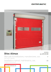
Ditec Alimax
0DT850
rev. 2015-05-08
Manual de instalação, manutenção e uso.
PT
(Instruções originais)
Installation manual, maintenance, use.
(Original instructions)
www.ditecentrematic.com
EN
ÍNDICE DOS ASSUNTOS
Cap.
Assunto ....................................................................................................................................... Pág.
1.
2.
3.
4.
ADVERTÊNCIAS GERAIS PARA A SEGURANÇA .............................................................................. 2
CARACTERÍSTICAS TÉCNICAS ........................................................................................................ 3
INSTALAÇÃO MECÂNICA ................................................................................................................. 4
LIGAÇÕES ELÉTRICAS 5QEX
4.1 Ligações quadro elétrico / automação ....................................................................................... 5
4.2 Fotocélulas de segurança .......................................................................................................... 5
QUADRO ELETRÓNICO
5.1 Alimentação e proteção .............................................................................................................. 6
5.2 Ligações motor e encoder .......................................................................................................... 7
5.3 Ligações entradas ...................................................................................................................... 8
5.4 Gopav ligação e sincronização ................................................................................................... 9
REGULAÇÕES E ARRANQUE
6.1 Botoeira .................................................................................................................................... 10
6.2 Regulação dos fins de curso ................................................................................................... 10
6.3 Regulação fim da posição de fecho ......................................................................................... 11
6.4 Regulação fim da posição de abertura .................................................................................... 11
6.5 Programação do tempo de fecho ............................................................................................ 12
ANOMALIAS E SOLUÇÕES
7.1 Funções..................................................................................................................................... 12
7.2 Panorâmica das mensagens ................................................................................................... 13
7.3 Erros relativos ao sistema interno F.9xx ................................................................................. 16
7.3.1 Mensagens de informação ................................................................................................... 16
MANUAL DE USO E LIMPEZA PARA AMBIENTES ALIMENTARES ............................................. 20
AMSES ............................................................................................................................................ 21
9.1 Ligação função interbloqueio e airlock .................................................................................... 21
5.
6.
7.
8.
9.
1. AVISOS GERAIS PARA A SEGURANÇA
O presente manual de instalação é para o uso exclusivo de pessoal profissionalmente especializado.
A instalação, as ligações elétricas e as regulações devem ser efetuadas no respeito da Boa Técnica e de acordo com
as normas vigentes.
Ler atentamente as instruções antes de iniciar a instalação do produto. Uma instalação errada pode ser fonte de perigo.
Os materiais da embalagem (plástico, isopor, etc.) não devem ser abandonados no ambiente e não devem ser deixados ao
alcance de crianças porque são fontes potenciais de perigo.
Antes de iniciar a instalação, verificar a integridade do produto. Não instalar o produto em ambiente e atmosfera explosivos:
presença de gases ou fumos inflamáveis constituem um grave perigo para a segurança. Antes de instalar a porta, efetuar
todas as reformas de estrutura relativas à realização dos suportes de segurança e à proteção ou isolamento de todas as
zonas de esmagamento, cisalhamento, deslocamento e de perigo em geral.
Verificar que a estrutura existente tenha os requisitos necessários de resistência e estabilidade. Os dispositivos de segurança
(fotocélulas, partes sensíveis, parada de emergência, etc.) devem ser instalados levando em consideração: as normas e as
diretrizes em vigor, os critérios da Boa Técnica, o ambiente de instalação, a lógica de funcionamento do sistemas e as forças
desenvolvidas pela porta ou portão motorizados.
Os dispositivos de segurança devem proteger eventuais zonas de esmagamento, cisalhamento, deslocamento e de perigo
em geral, da porta. Aplicar as sinalizações previstas pelas normas vigentes para marcar as zonas perigosas.
Cada instalação deve manter visível a indicação dos dados identificativos da porta.
Antes de ligar a alimentação elétrica verificar que os dados da placa sejam correspondentes àqueles da rede de
distribuição elétrica. Prever na rede de alimentação um interruptor/disjuntor unipolar com distância de abertura dos
contatos igual ou superior a 3 mm. Verificar que a montante da instalação elétrica haja um interruptor diferencial e uma
proteção de excesso de corrente adequados. Ligar a porta a uma instalação de aterramento eficaz executada conforme
previsto pelas normas de segurança em vigor. O fabricante da porta se exime de qualquer responsabilidade caso sejam
instalados componentes incompatíveis para fins da segurança e do bom funcionamento ou caso sejam efetuadas alterações
de qualquer natureza sem a autorização específica do fabricante. Para a eventual reparação ou substituição dos produtos
deverão ser utilizados exclusivamente peças de reposição originais Entrematic Group AB. O instalador deve fornecer todas
as informações relativas ao funcionamento automático, manual e de emergência da porta ou portão motorizados, e entregar
ao utilizador da instalação as instruções de uso.
Acessório opcional
Top W
Todos os direitos são reservados
Os dados indicados foram redigidos e verificados com o máximo cuidado. Contudo, não podemos assumir qualquer
responsabilidade por eventuais erros, omissões ou aproximações devidas a exigências técnicas ou gráficas.
0DT850 2015-05-08
-2-
PT
6
2
4
8
9
7
17
1
5
19
10
11
26
3
25
24
23
22
21
15
20
18
13
16
14
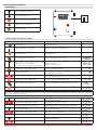
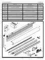
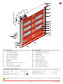
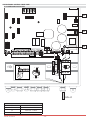
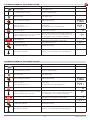
Ref.
1
2
3
4
5
6
7
8
9
10
11
12
13
12
Descrição
Porta lateral esquerda
Porta lateral direita
Abertura de reintrodução do painel esquerdo
Abertura de reintrodução do painel direito
Tampa Cabeçote esquerdo
Tampa Cabeçote direito
Motorredutor com encoder
Eixo de Enrolamento
Tampa do contentor
Acionamento manual com barra e cobertura
Caixa de ligação
Transmissor faixa de segurança (Top W)
Borda inferior com lastro de areia
Ref.
14
15
16
17
18
19
20
21
22
23
24
25
26
Descrição
Placa de fixação no pavimento esquerda
Placa de fixação no pavimento direita
Coluna direita
Coluna esquerda
Tampa coluna esquerda
Tampa coluna direita
Quadro eletrónico
Fotocélula de segurança (Top W)
Painel em poliéster
Tubo reforço painel
Janelas em PVC transparente
Espessuras de compensação
Placas de reforço painel
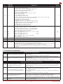
2. CARACTERÍSTICAS TÉCNICAS
Tensão de alimentação ......................... 230 V, 50/60 Hz
Absorção de linha ................................................... 16 A
Alimentação comandos auxiliares ................... 24V
Potência motor ................................................. 0,75 KW
Grau de proteção quadro de comando ...................IP 54
Temperatura de utilização .............................- 5 + 50 °C
Máxima humidade relativa ............................. 80 ÷ 90%
Dimensionar corretamente a seção dos condutores de linha consultando a absorção indicada e considerando o
comprimento e a colocação dos cabos.
-3-
0DT850 2015-05-08
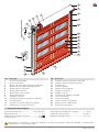
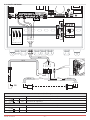
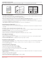
3. INSTALAÇÃO MECÂNICA
Ver os desenhos relativos à instalação mecânica nas páginas 24 - 25 (folha central a destacar)
3.1 Verificações do vão de passagem (fig.1)
ƒ Verificar as dimensões do vão e a correspondência com as medidas totais da porta fornecida, considerando as eventuais
tolerâncias necessárias no caso de instalação em luz.
ƒ Verificar que eventuais obstáculos existentes não dificultem a montagem da estrutura.
ƒ Verificar que os suportes de apoio sejam nivelados e eventualmente restaurá-los mediante calços adequados.
ƒ Verificar a consistência da estrutura do vão: deve ser garantida uma ancoragem segura mediante suportes ou buchas.
No caso de pouca ou duvidosa consistência é necessário realizar uma estrutura metálica autoportante adequada.
ƒ Os materiais e os equipamentos utilizados para a fixação da porta à estrutura devem ter características adequadas às
normas higiénicas do local de instalação.
Ao final da instalação da porta, realize a limpeza e higienize toda a zona circundante.
3.2 Posicionamento das colunas verticais (fig.2)
ƒ Mensurar o vão L e detectar a posição do eixo L/2.
ƒ Utilizando o eixo (L/2), centralizar a dimensão de passagem horizontal PL, em cujas extremidades deverá ser marcada no
pavimento a posição exata dos montantes verticais.
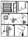
3.3 Fixação das colunas e posicionamento dos bloqueios dos cabeçotes (fig.3 - 4 - 5)
ƒ Fixar as bases na correspondência das marcas ou a coluna na parede (cortando a coluna em função da altura de instalação)
por meio das buchas específicas, de dimensão M8.
ƒ Nivelar os montantes verticais e fixá-los utilizando os grampos móveis de fixação provisórios.
ƒ Verificar a posição ortogonal da montagem mensurando as diagonais.
ƒ Marcar a fixação dos cabeçotes laterais e preparar a fixação através das buchas específicas de dimensão M8.
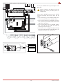
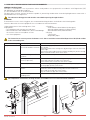
3.4 Montagem dos cabeçotes (fig. 6)
ƒ Montar os cabeçotes laterais ao eixo de enrolamento.
ƒ Direcionar a flange de fixação como indicado na figura (6A), de maneira tal que a montagem do dispositivo de desbloqueio
manual fique correta.
ƒ Fazer sair os cabos do motor e do encoder (A) no centro dos cabeçotes.
ƒ Fixar o cabeçote esquerdo por meio dos três parafusos (B) e o cabeçote direito por meio do parafuso (C).
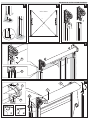
3.5 Instalação do eixo de enrolamento (fig.7)
ƒ Levantar com cuidado o eixo com uso de empilhadeira ou outro meio de elevação, certificando-se que não possa cair
durante a fase de elevação e protegendo a cortina de eventuais danos.
ƒ Inserir os cabeçotes nos montantes verticais, inserindo os cabos das fotocélulas (D) nos alojamentos específicos, para
evitar que se danifique.
ƒ Fixar os cabeçotes laterais de maneira bem firme (E).
3.6 Dispositivo de acionamento manual, opcional (fig.8)
ƒ Inserir e fixar o dispositivo (F) por meio dos 4 parafusos que foram fornecidos.
ƒ Ligar o microinterruptor de segurança como indicado na pág. 8.
ƒ Testar o funcionamento correto acionando a manobra manual por meio da haste fornecida.
ƒ Inserir a borda inferior do painel nos trilhos das colunas (fig.9).
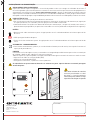
3.7 Posicionamento das coberturas (fig.10)
ƒ Instalar a cobertura do eixo de enrolamento inserido nos dois pinos posteriores (G) dos cabeçotes e fixado pelos dois pinos
dianteiros (H) e pelos parafusos específicos (I).
ƒ Alojar o cabo de ligação das fotocélulas (L) no alojamento específico.
ƒ Posicionar as tampas laterais dos cabeçotes.
ƒ Quando estiver presente o dispositivo de acionamento manual, inserir a tampa de borracha específica (M).
ƒ Fixar as tampas laterais dos montantes (opcional).
0DT850 2015-05-08
-4-
PT
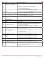
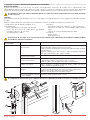
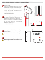
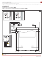
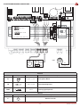
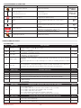
4. LIGAÇÕES ELÉTRICAS
4.1 Ligações do quadro elétrico / motor / seguranças
ǩ1DȌJXUDIRUDPPRVWUDGRVHVTXHPDWLFDPHQWHRVFDERVIRUQHFLGRVHVXDSRVL©¥RQDSRUWDFDGDȌD©¥R«PDUFDGDFRP
um código colocado sobre uma etiqueta adesiva.
4.2 Fotocélulas de segurança
ǩ([HFXWDUDVOLJD©·HVSUHVHQWHVQDSRUWDFRQIRUPHLQGLFDGRQDfig.11).
ǩ([HFXWDUDVOLJD©·HVQRTXDGURHOHWUµQLFRFRQIRUPHLQGLFDGRQRHVTXHPDHO«WULFRpar. 5.3).
11
SB
M
E
8553B
8568
M
F
M
E
8562
8638
OFF
ON
8553A
Tx
8553B
Rx
Dimensionar corretamente a seção dos condutores de linha consultando a absorção indicada e considerando o
comprimento e a colocação dos cabos.
-5-
0DT850 2015-05-08
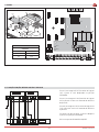
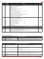
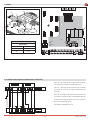
5. QUADRO ELETRÓNICO
5.1 ALIMENTAÇÃO E PROTEÇÃO
F1
F2
Si3 Si4
Si1 Si212V
F3
T1 T2 T3
PE
24 V
4
7
6
9 11 13 15 17 19 21 23 25 27 29 31
8 10 12 14 16 18 20 22 24 26 28 30 32
41 43 45 51 54
N N
L
42 44 46 53 53
ØV
Azul
Preto
N
Azul
2
5
Preto
3
Amarelo-Verde
1
X1
L1 L1
111
112
113
211
PE
212
L
N
311
312
L
N
313
L
N
230V AC
FUSÍVEIS
IDENTIFICAÇÃO
Valores
F1
T 250mA - L 250V
F2
T 500mA - L 250V
F3
T 3.15A - 230V
0DT850 2015-05-08
-6-
PT
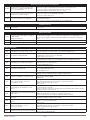
5.2 LIGAÇÕES MOTOR E ENCODER
Si3 Si4
Si1 Si212V
T1 T2 T3
PE
24 V
1
3
2
5
4
7
6
9 11 13 15 17 19 21 23 25 27 29 31
8 10 12 14 16 18 20 22 24 26 28 30 32
X1
L1 L1
41 43 45 51 54
N N
42 44 46 52 53
ØV
111
112
41 43 45
113
Porta aberta
211
NO C NC
42 44 46
212
Porta fechada
311
312
Prêto U/L1
Prêto V/L2
Prêto W/L3
Amarelo/Verde
Prêto
Branco
NO C NC
Branco
Amarelo
Verde
Marrom
Painel
Contactos livres máx. 230 V - 3 A
L
N
313
LAMP
E
M
113
LK
N
SAÍDAS
REF
Saída
Valor
M
UWV
M
3~
Descrição
230 V~ / 10 A
Motor trifásico
LK
230 V = 0,2 A
Solenoide travão de estacionamento
LAMP
230 V
Intermitente (opcional)
ENTRADAS
REF
Saída
Descrição
E
E
Encoder absoluto
-7-
0DT850 2015-05-08
5.3 LIGAÇÕES ENTRADAS
Si4
Si1 Si212V
T1 T2 T3
PE
24 V
1
3
2
5
4
7
6
9 11 13 15 17 19 21 23 25 27 29 31
8 10 12 14 16 18 20 22 24 26 28 30 32
X1
L1 L1
41 43 45 51 54
N N
L
42 44 46 52 53
N
ØV
111
112
113
211
1
212
7
5
2
6
8
311
L
N
313
Branco
Vermelho
Marrom
Preto
Azul
Fecha
Abre
Paragem
312
Comandos externos
8562
Azul
Preto
Azul
Marrom
Preto
Branco
Vermelho
8638
8568
Azul
Preto
8553A
4 3
Azul
Marrom
Azul
Marrom
Preto
8553B
11 28
SB
12 11 28
Tx
Rx
SEGURANÇAS 1-2 (NC) Paragem externa
Contato
Descrição
3
4
N.C
Micro-contato de segurança desbloqueio acionamento manual
11
12
N.C
Fotocélula de segurança
COMANDOS
Contato
Descrição
5
6
N.O
Comando de abertura
7
8
N.O
Comando de fecho
0DT850 2015-05-08
-8-
PT
5.4 GOPAV LIGAÇÃO E SINCRONIZAÇÃO
Si4
Si1 Si212V
T1 T2
8.2 kΩ
24 V
1
3
2
5
4
7
6
9 11 13 15 17 19 21 23 25 27 29 31
8 10 12 14 16 18 20 22 24 26 28 30 32
41 43 45 51 54
42 44 46 52 53
Ligar o dispositivo GOPAVT removendo a placa
lateral (B).
Atenção: remover a bateria da unidade
móvel antes de proceder com a
configuração.
ØV
Alimentar a unidade fixa GOPAVR e
normalmente ficarão intermitentes os leds W e
o contato OUT1 será aberto:
ƒ inserir a bateria da unidade móvel GOPAVT no
alojamento específico, todos os leds presentes
QDXQLGDGHPµYHOȌFDU¥RLQWHUPLWHQWHV
ƒ premir a tecla (A) da unidade fixa GOPAVR: o
led W da unidade fixa e o led OC da unidade
móvel ficará intermitente
ƒ premir a tecla (A) da unidade móvel GOPAVT,
os leds da unidade móvel e da unidade fixa
GHVOLJDU¥R
ƒ verificar a configuração correta ativando a
faixa sensível e verificando o acendimento do
led W na unidade fixa GOPAVR e do led IN.
A
IN1
GOPAVR
OUT1
SC
OC
W
0 1
B
GOPAVT
IN2
IN1
SC
OC
A
-9-
0DT850 2015-05-08
6. REGULAÇÕES E ARRANQUE
6.1 BOTOEIRA
Ativa a manobra de abertura.
Ativa a manobra de fecho.
ON
S1
Ativa e desactiva a função de STOP.
Desbloqueio de emergência
Interruptor geral
OFF
ON
6.2 REGULAÇÃO DOS FINS DE CURSO
COMANDO
OFF
FUNÇÃO
Interruptor geral
Tirar alimentação
Colocar o dip-switch S1 em ON
Habilitação programação parâmetros
Interruptor geral
Dar alimentação
Premir o botão de Emergência
Habilitação introdução parâmetros
DISPLAY
ON
S1
ON
3
Botão "Abre" ou "Fecha" Busca dos
Localizar o P.210:
parâmetros a sere configurados
calibração do fim de curso
Nota: nem todos os parâmetros são visíveis
Premir botão "Stop" impulso breve
Premir o botão "Abre"
Premir botão "Stop" impulso longo
3
Visualiza conteúdo parâmetro
Aumentar o valor configurado
Os pontos estão intermitentes
Salva o novo valor configurado
Premir até quando os botões intermitentes desligarem
Premir botão "Stop" impulso breve
Retorno à visualização dos parâmetros
Retirar o botão de Emergência
Acesso à modalidade de calibração do fim de curso
Premir botão "Stop" impulso breve
Regulação do fim de curso em fecho habilitada
Verificar o sentido de rotação do motor ("abre"/"fecha"). Caso esteja errado, entrar no parâmetro
rotação trocando o valor de a Comando de fecho com "homem presente" até a
posição de porta fechada
Premir botão "Stop" impulso longo
Salva a posição de "porta fechada"
O sistema arranca automaticamente
Regulação do fim de curso em abertura habilitada
Premir o botão "Abre"
Comando de abertura com "homem presente" até a
posição de porta aberta
Premir botão "Stop" impulso longo
Salva a posição de "porta aberta"
O sistema arranca automaticamente
Regulação fim de curso intermediário habilitada
Premir o botão "Fecha"
Comando de fecho com "homem presente" até a
posição intermediária
Premir botão "Stop" impulso longo
Salva a posição intermediária
- 10 -
3 e modificar o sentido de
Premir o botão "Fecha"
0DT850 2015-05-08
3
>$O
( (9
( (9
( (9
( (R
( (R
( (R
( (,
( (,
( (,
PT
6.3 REGULAÇÃO FIM DA POSIÇÃO DE FECHO
COMANDO
OFF
FUNÇÃO
DISPLAY
Interruptor geral
Tirar alimentação
Colocar o dip-switch S1 em ON
Habilitação programação parâmetros
Interruptor geral
Dar alimentação
Premir o botão de Emergência
Habilitação introdução parâmetros
3
dos Localizar o P.221:
calibração fim da posição de fecho
3
ON
S1
ON
Botão "Abre" ou "Fecha" Busca
parâmetros a sere configurados
Premir botão "Stop" impulso breve
Visualiza conteúdo parâmetro
O corretor + para o fecho mais para cima e o corretor –
Botão "Abre" (lado +) ou "Fecha (lado -) para mais para baixo
configurar a correção de quota
Ex.: – 3, o corretor deslocará o ponto de fecho para o
pavimento
Salva o novo valor configurado
Premir botão "Stop" impulso longo
Premir até quando os botões intermitentes desligarem
Premir botão "Stop" impulso breve
Retorno à visualização dos parâmetros
Retirar o botão de Emergência
Acesso à modalidade de funcionamento normal
Abrir e fechar a porta
Verificar o ponto de abertura correto
*
3
6.4 REGULAÇÃO FIM DA POSIÇÃO DE ABERTURA
COMANDO
OFF
FUNÇÃO
DISPLAY
Interruptor geral
Tirar alimentação
Colocar o dip-switch S1 em ON
Habilitação programação parâmetros
Interruptor geral
Dar alimentação
Premir o botão de Emergência
Habilitação introdução parâmetros
3
Localizar o P.231: calibração fim da posição de fecho
3
ON
S1
ON
Botão "Abre" ou "Fecha" Busca
parâmetros a sere configurados
Premir botão "Stop" impulso breve
dos
Visualiza conteúdo parâmetro
O corretor + para a abertura mais para cima e o
Botão "Abre" (lado +) ou "Fecha (lado -) para corretor – mais para baixo
configurar a correção de quota
Ex.: + 3, o corretor deslocará o ponto de fecho para o
pavimento
Salva o novo valor configurado
Premir botão "Stop" impulso longo
Premir até quando os botões intermitentes desligarem
Premir botão "Stop" impulso breve
Retorno à visualização dos parâmetros
Retirar o botão de Emergência
Acesso à modalidade de funcionamento normal
Abrir e fechar a porta
Verificar o ponto de abertura correto
- 11 -
*
3
0DT850 2015-05-08
6.5 PROGRAMAÇÃO DO TEMPO DE FECHO
COMANDO
Premir o botão de Emergência
Botão "Abre" ou "Fecha" Busca
parâmetros a sere configurados
Premir botão "Stop" impulso breve
Premir o botão "Abre"
Premir o botão "Fecha"
Premir botão "Stop" impulso longo
Premir botão "Stop" impulso breve
Retirar o botão de Emergência
FUNÇÃO
DISPLAY
Habilitação introdução parâmetros
dos Localizar o P.010:
Configuração do tempo de fecho
3
3
Visualiza o conteúdo do parâmetro (valor
predeterminado)
Aumenta o tempo de fecho
Caso o valor seja modificado, os pontos decimais
ficarão intermitentes.
Diminui o tempo de fecho
Caso o valor seja modificado, os pontos decimais
ficarão intermitentes.
Salva o novo valor configurado
Premir até quando os botões intermitentes desligarem
Permite anular a configuração dos parâmetros.
Será restabelecido o valor predeterminado
*
*
Acesso à modalidade de funcionamento normal
7. ANOMALIAS E SOLUÇÕES
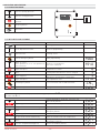
7.1 FUNÇÕES
P.
Intervalo (unidade)
Funções da porta
Visualização do número de ciclos da porta
Visualização: 1234567 → 1234. ź-premir .567
Visualização:
67 → 67
Tempo de manutenção da posição aberta (posição de fim de curso superior – Eo)
0 = dispositivo de fecho automático desativado.
Tempo de manutenção da posição aberta (paragem intermediária - E1)
0: fecho automático desativado
Tempo de aviso antes da abertura
O movimento de abertura fica mais lento após o recebimento do comando de OPEN com
um período de tempo especificado neste parâmetro.
Prestar atenção na unidade. Caso desejar configurar um aviso de 4 segundos, modificar
o parâmetro P.020 para 400.
Tempo de aviso antes do fecho
O movimento de fecho fica mais lento após o recebimento do comando de CLOSE ou
ao se encerrar o tempo do fecho automático (fecho forçado) com um período de tempo
especificado neste parâmetro.
Default
000
(ciclos)
010
(s) 0….200
011
(s) 0….200
020
(ms) 0….1000
025
(s) 0….20
P
100
101
102
Intervalo (unidade)
Dados nominais do motor
(Hz) 30…200
Frequência nominal do motor (ver a etiqueta, nota: Y/Δ)
(A) 0…9,9
Corrente nominal do motor (ver a etiqueta, nota: Y/Δ)
( % ) 40…100
Fator de potência cosM (ver a etiqueta: cos M: 0.63 →63)
Tensão nominal do motor (ver a etiqueta, nota: Y/Δ). As curvas das características do
(V) 100…500
motor é calculada automaticamente com base na frequência e na tensão nominais.
Campo rotacional do motor
0...1
0: Rotação direita
1: Rotação esquerda
Default
-1
-1
-1
Intervalo (unidade)
Indicação das posições do fim de curso com as paragens eletrónicas
Seleção da posição da calibração na modalidade "homem presente" ("teach in"):
0: no → Nenhuma/Anula
1: Eu → Interruptor de fim de curso inferior e superior (parada intermediária: ver P244)
2: Eo → Interruptor de fim de curso superior (parada intermediária: ver P244)
3: uo → Interruptor de fim de curso inferior e superior
4: E1 → Interruptor de fim de curso intermediário (P244 é ignorado)
5: al → (all) Interruptor de fim de curso inferior, superior e intermediário (P244)
Default
Correção das posições do fim de curso com as paragens eletrónicas
Valor de correção para os fins de curso inferiores (configurado em 0 somente com uma
nova calibração).
Valor de correção para os fins de curso superiores (configurado em 0 somente com uma
nova calibração).
Default
103
130
P
210
P
0….5
Intervalo (unidade)
221
(Ink) ± 125
231
(Ink) ± 60
0DT850 2015-05-08
- 12 -
4
10
0
0
-1
1
O
O
O
PT
P
910
920
Intervalo
(unidade)
0…15
Eb1
Eb2
Eb3
Eb4
Ebcl
Eb
925
930
940
{s} 0….120,0
{V}
980
0….2
Diagnóstico
Default
Seleção da modalidade de visualização (solicitada através do botão de PARAGEM ou
durante o movimento do motor)
0: Sequência do controller (modalidade automática)
1: {Hz} Frequência do campo rotatório atual
2: {A} Corrente do motor atual (> 1A)
3: {V} Corrente do motor atual
4: {A} Corrente da ligação atual (corrente efetiva)
5: {V} Tensão de ligação
6: {°C} Temperatura final em °C
7: {°C} Temperatura final em °F
8: Último tempo de funcionamento mensurado (1/10 a 99,9 seg, 1/1 de 100 seg)
Aplicável somente para os fins de curso eletrónicos
9: [Ink] progresso da posição atual
10: [Ink] posição de referência atual
11: [dig] valor do canal 1 do codificador absoluto atual
12: [dig] valor do canal 2 do codificador absoluto atual
13: [dig] tensão de referência atual (2,5 V)
14: Temperatura na estrutura em (°C)
15: Temperatura na estrutura em (°F)
Visualização das mensagens de erro/avarias
Abrir premindo novamente a tecla de paragem
Ativar/Desativar através da tecla de abertura/fecho
Fechar premindo novamente a tecla de paragem.
Terminar a operação anulando "EB-"
ǩ(EǵPHQVDJHQVGHHUURPDLVUHFHQWHRX (U
ǩ(EǵPHQVDJHQVGHHUUR
(U
ǩ(EǵPHQVDJHQVGHHUUR
(U
ǩ(EǵPHQVDJHQVGHHUUR
(U
ǩ(EFOǵHOLPLQDUWRGRVRVHUURVQDPHPµULD
ǩ(Eǵ$QXODU
(Visualizar noEr: nenhum erro).
Visualização da versão do software.
Tempo de funcionamento do motor durante o último movimento da porta
Visualização da tensão de alimentação da linha
Modalidade de manutenção
0: Automático (abertura e fecho na posição de manutenção)
1: Homem presente fechado (modalidade manual fechada/modalidade automática aberta)
2: Homem presente (modalidade manual para posição aberta e fechada)
(PHUJ¬QFLDKRPHPSUHVHQWHDEHUWRHIHFKDGRWRGRVRVHUURVHDVSURWH©·HVV¥R
ignoradas)
O
Eb 1
0
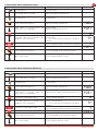
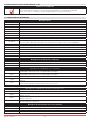
7.2 PANORÂMICA DAS MENSAGENS
F.000
F.005
F.020
F.030
F.031
F.043
Posições erradas do fim de curso
- Valor do parâmetro muito baixo para a paragem de emergência do fim de
Posição errada na parte superior da
curso superior.
porta.
- Intervalo (faixa) do fim de curso superior muito baixo.
- Valor do parâmetro muito baixo para a paragem de emergência do fim de
curso inferior.
Posição errada na parte inferior da
- Intervalo (faixa) do fim de curso inferior muito baixo.
porta.
- Travão mecânico defeituoso ou configurado de maneira errada.
Imprecisões relativas aos movimentos da porta
- O tempo de funcionamento atual do motor excedeu o valor máximo
Excedimento do tempo de
configurado. A porta pode funcionar de maneira anormal ou ficar travada.
funcionamento (durante a abertura,
- Um dos fins de curso não começou a funcionar com a ativação dos fins de
o fecho ou a utilização "homem
curso mecânicos.
presente")
- A porta ou o motor está bloqueado
- Desempenho insuficiente para o binário necessário
- Velocidade insuficiente
Erros de tração (não foi alcançada a
posição predeterminada para a porta) - Fixação insuficiente ao eixo do detector de valores absolutos ou do detector
incremental
- Sistema de posicionamento errado em uso (P.205).
- Quando se utiliza um detector incremental: Os canais A e B foram trocados
- A direção de rotação do motor foi alterada na fase de calibração
A direção de rotação registrada é
- Abaixamento excesso durante o arranque, ativação dos travões
diversa daquela prevista.
antecipadamente ou binário insuficiente. Se necessário, regular a tensão.
Erro no fim de curso dianteiro da barra - O fim de curso dianteiro da barra luminosa se encontra na posição de fim de
luminosa
curso central e superior.
- 13 -
0DT850 2015-05-08
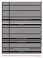
F.050
F.051
F.052
F.090
F.201
F.211
F.212
Mensagem de erro do detector incremental
- A paragem de referência é ativada todas as vezes (defeituosa).
A posição da paragem de referência
- A paragem de referência é ativada muito longe da referência selecionada.
não está incluída no intervalo aceitável
- A paragem de referência é ativada perto da correia do fim de curso.
durante a sincronização cíclica.
- O P270 e o P280 estão na paragem de referência.
- A paragem de referência foi posicionada perto da correia do fim de curso.
A posição da paragem de referência
- A paragem de referência foi posicionada além de 15% EO.
não está incluída no intervalo aceitável.
- A paragem de referência é defeituosa.
- Durante a sincronização após a ativação, a paragem de referência não é
A paragem de referência não é
reconhecida até 20% EO.
reconhecida.
- A paragem de referência não é reconhecida na posição de fim de curso.
Os parâmetros foram atribuídos ao
comando.
Erros da corrente de segurança
A paragem de emergência foi interrompida na entrada da "paragem de
Botão "Paragem de emergência"
emergência interna" sem que tenha sido selecionada a modalidade de
interno ativado ou Watchdog
parametrização Interna ou Controlos EEPROM defeituosos. Premir a tecla de
(monitoragem do computador).
paragem para obter maios informações sobre a causa
Paragem de emergência externa 1 ativo. A paragem de emergência foi interrompida na entrada 1. (terminais 1 e 2)
Paragem de emergência externa 2
A paragem de emergência foi interrompida na entrada 2. (terminais 3 e 4)
ativo.
Erros da corrente de segurança
Foi encontrado um curto-circuito na
F.360
entrada da proteção.
Erro de redundância com curtoF.362
circuito.
F.363
Interrupção na entrada da proteção
F.364
Teste detector de obstáculos falho
F.365
Erro de redundância com interrupção
F.369
F.374
F.385
F.400
F.410
F.420
F.430
F.435
F.440
F.510
Parâmetro não configurado
Os parâmetros de base (P.205 e de P.100 a P.103) dos comandos TST FUE
ainda não foram configurados.
Foi encontrado um curto-circuito nas proteções com contato normalmente
fechado.
Um dos canais de elaboração para a detecção do curto-circuito reage de
maneira diferente do outro canal. → Placa controller defeituosa
Cabo de conexão defeituoso ou não conectado
Resistência de terminação errada ou ausente
Ponte J600 não configurado corretamente
Na solicitação do teste, o detector de obstáculos não foi ativado como previsto.
A hora da solicitação do teste e aquela da execução do mesmo não coincidem
Um dos canais de elaboração para a detecção da interrupção reage de
maneira diferente do outro canal.
→ Placa controller defeituosa
Parâmetros do detector de obstáculos
Detector interno de obstáculos conectado mas desativado
interno não configurados corretamente
Interruptor de pré-fim de curso do detector de obstáculos configurado de
maneira errada ou defeituoso
Teste borda sensível falho
Módulo de elaboração defeituoso
Detector de obstáculos defeituoso
Quando o detector de obstáculos é ativado, o interruptor de pré-fim de curso
Erro no interruptor de pré-fim de curso
para a desativação ou a inversão do detector de obstáculos permanece ativo
do detector de obstáculos
até na posição de fim de curso superior.
ǩ5X¯GRH[FHVVLYRQDWHQV¥RGHDOLPHQWD©¥R
Foi detectado um restabelecimento do
ǩ:DWFKGRJLQWHUQRDWLYR
hardware do controller
ǩ(UUR5$0
ǩ)RUDPFRQȌJXUDGRVGDGRVHUUDGRVGRPRWRU3Ǟ3
ǩ$XPHQWRGHWHQV¥RQ¥RUHJXODGRFRQȌJXUDGRRH[FHVVRGHDOLPHQWD©¥R
Excesso de corrente (corrente do
(P140 ou P145)
motor ou circuito intermediário).
ǩ'LPHQVLRQDPHQWRGRPRWRUGDSRUWDQ¥RFRUUHWR
ǩ$ODYDQFDSRUWD
ǩ,QWHUUXSWRUWUDY¥RFRPLQWHUIHU¬QFLDVGHIHLWXRVRDXVHQWH
Sobretensão do circuito intermediário ǩ$WHQV¥RGHDOLPHQWD©¥RHVW£PXLWRHOHYDGD
ǩ2PRWRUGHYROYHPXLWDHQHUJLDQDPRGDOLGDGHJHUDGRU«LPSRVV¯YHOUHGX]LU
Limite 1.
suficientemente a energia de movimento da porta
ǩ&DUJDQDVIDVHVȌQDLVRXQRLQWHUUXSWRUGRWUDY¥RPXLWRHOHYDGD
A temperatura da unidade de
ǩ7HPSHUDWXUDDPELHQWHPXLWREDL[DSDUDRIXQFLRQDPHQWRGRFRQWUROOHU
resfriamento superou o limite do
ǩ)UHTX¬QFLDGHFORFNGDIDVHȌQDOPXLWRHOHYDGD3DU¤PHWUR3
intervalo de funcionamento 1.
Erro: aumento da temperatura interna ǩ&DUJDQRFRQYHUVRUGHIUHTX¬QFLDFLUFXLWRPXLWRHOHYDGD
acima de 75 °C.
ǩ&HQWUDOGRFRQWUROOHUQ¥RVXȌFLHQWHPHQWHUHVIULDGD
ǩ([FHVVRGHDOLPHQWD©¥RQ¥RUHJXODGR
Sobretensão do circuito intermediário
ǩ'LPHQVLRQDPHQWRGRPRWRUGDSRUWDQ¥RFRUUHWR
Limite 1.
ǩ$ODYDQFDSRUWD
ǩ)RUDPFRQȌJXUDGRVGDGRVHUUDGRVGRPRWRU3Ǟ3
ǩ$XPHQWRGHWHQV¥RQ¥RUHJXODGRFRQȌJXUDGRRH[FHVVRGHDOLPHQWD©¥R
Excesso de corrente do motor/circuito
(P140 ou P145)
intermediário Limite 2.
ǩ'LPHQVLRQDPHQWRGRPRWRUGDSRUWDQ¥RFRUUHWR
ǩ$ODYDQFDSRUWD
0DT850 2015-05-08
- 14 -
F.511
F.515
F.519
F.520
F.521
F.524
F.530
F.535
F.540
F.700
F.720
F.750
F.751
F.752
F.760
F.761
F.762
PT
Problema com injeção de corrente para ǩ&RQWURODURVSDU¤PHWURVGH3D3
frear
ǩ7HQWDUUHGX]LU3H3
ǩ&RQȌJXUD©¥RFXUYDPRWRUHUUDGDFRUUHQWHQRPLQDOGRPRWRU3
A função de proteção do motor
ǩ([FHVVRGHDOLPHQWD©¥RPXLWRHOHYDGD3RX3
encontrou um excesso de corrente
ǩ0RWRUGLPHQVLRQDGRQ¥RFRUUHWDPHQWH
ǩ&XUWRFLUFXLWRRXHUURGHDWHUUDPHQWRQRVWHUPLQDLVGRPRWRU
ǩ&RQȌJXUD©¥RFRUUHQWHQRPLQDOGRPRWRUHUUDGD3
O chip do acionador IGBT detectou um ǩ([FHVVRGHDOLPHQWD©¥RPXLWRHOHYDGD3RX3
ǩ0RWRUGLPHQVLRQDGRQ¥RFRUUHWDPHQWH
excesso de corrente
ǩ)XQFLRQDPHQWRGHIHLWXRVRGRPRWRU
ǩ,QWHUUXS©¥RPRPHQW¤QHDGRFLUFXLWRGHSDUDGDGHHPHUJ¬QFLD
ǩ,QWHUUXSWRUWUDY¥RFRPLQWHUIHU¬QFLDVGHIHLWXRVRDXVHQWH
Sobretensão do circuito intermediário ǩ$WHQV¥RGHDOLPHQWD©¥RHVW£PXLWRHOHYDGD
ǩ2PRWRUGHYROYHPXLWDHQHUJLDQDPRGDOLGDGHJHUDGRU«LPSRVV¯YHOUHGX]LU
Limite 2.
suficientemente a energia de movimento da porta
ǩ$OLPHQWD©¥RGHHQWUDGDPXLWREDL[DJHUDOPHQWHQDFRQGL©¥RGHFDUJD
Sobretensão do circuito intermediário
ǩ&DUJDQDVIDVHVȌQDLVRXQRLQWHUUXSWRUGRWUDY¥RPXLWRHOHYDGD
ǩ6REUHFDUJDVHPFXUWRFLUFXLWR
Ext. Alimentação externa a 24 V não
ǩ(PFDVRGHFXUWRFLUFXLWRHPXPDWHQV¥RGH9RFRQWUROOHUQ¥RDFHOHUDH
presente ou muito baixa.
se acende uma lâmpada de luminescência V306.
ǩ&DUJDQDVIDVHVȌQDLVRXQRLQWHUUXSWRUGRWUDY¥RPXLWRHOHYDGD
A temperatura da unidade de
ǩ7HPSHUDWXUDDPELHQWHPXLWREDL[DSDUDRIXQFLRQDPHQWRGRFRQWUROOHU
resfriamento superou o limite do
ǩ)UHTX¬QFLDGHFORFNGDIDVHȌQDOPXLWRHOHYDGD3DU¤PHWUR3
intervalo de funcionamento 1.
Erro: aumento crítico da temperatura
ǩ7HPSHUDWXUDLQWHUQDPXLWRHOHYDGD
interna acima de 80 °C.
ǩ([FHVVRGHDOLPHQWD©¥RQ¥RUHJXODGR
Sobretensão do circuito intermediário
ǩ'LPHQVLRQDPHQWRGRPRWRUGDSRUWDQ¥RFRUUHWR
Limite 2.
ǩ$ODYDQFDSRUWD
Para interruptores de fins de curso eletrónicos:
ǩ$SµVVROLFLWDUDDWLYD©¥RGRVSDU¤PHWURVSUHGHWHUPLQDGRVSDU¤PHWURV
P.990), não foram configurados os parâmetros do sistema de
posicionamento correspondente.
Detecção da posição errada
ǩ$FDOLEUD©¥RQ¥RIRLFRPSOHWDGDRX«HUUDGD'HYHVHUUHSHWLGD
ǩ4XDQGRIRUDWLYDGDDSDUDGDLQWHUPHGL£ULDHVWHFRPDQGR«LPSURY£YHO
ǩ6LQFURQL]D©¥RQ¥RFRQFOX¯GDRXLQWHUUXSWRUGHUHIHU¬QFLDGHIHLWXRVR
ǩ$SRVL©¥RGHSDUDJHPLQWHUPHGL£ULD«LQIHULRUDRYDORULQFUHPHQWDOP¯QLPR
(25).
ǩ6LQFURQL]D©¥RQ¥RFRQFOX¯GD
ǩ2LQWHUUXSWRUGHUHIHU¬QFLDVHOHFLRQDGRQ¥RIRLDOFDQ©DGRRXHVW£IRUDGR
Erro de sincronização na detecção da
limite de tolerância
posição com codificador
ǩ2FRGLȌFDGRULQFUHPHQWDOQ¥RHVWDFRQWDQGRRXDSRUWDHVW£EORTXHDGDDW«
com erro de atraso F.030)
ǩ)RUDPLQYHUWLGDVDVHQWUDGDVLQFUHPHQWDLV,1H,1DW«HUURGHURWD©¥R
F.031)
Erro Transmissão de protocolo
ǩ+DUGZDUHGHIHLWXRVRRXSUHVHQ©DGHUX¯GRHO«WULFRQRDPELHQWH
Sincronização FU <-> codificador
ǩ+DUGZDUHGHIHLWXRVRRXSUHVHQ©DGHUX¯GRHO«WULFRQRDPELHQWH
absoluto
ǩ(OHWUµQLFDGRSURFHVVDGRUGRFRGLȌFDGRUDEVROXWRGHIHLWXRVR
ǩ&DERLQWHUIDFHGHIHLWXRVRLQWHUURPSLGR
Tempo
ǩ(OHWUµQLFDGRSURFHVVDGRUGRFRGLȌFDGRUDEVROXWRGHIHLWXRVR
de transmissão do protocolo vencido
ǩ+DUGZDUHGHIHLWXRVRRXSUHVHQ©DGHUX¯GRHO«WULFRQRDPELHQWH
ǩ$FLRQDPHQWRGRFRGLȌFDGRUGHSRVL©¥RGHIHLWXRVR
Posição fora do intervalo
ǩ(OHWUµQLFDGRSURFHVVDGRUGRFRGLȌFDGRUDEVROXWRGHIHLWXRVR
ǩ+DUGZDUHGHIHLWXRVRRXSUHVHQ©DGHUX¯GRHO«WULFRQRDPELHQWH
A distância entre o canal 1 e o canal
ǩ$FLRQDPHQWRGRFRGLȌFDGRUGHSRVL©¥RGHIHLWXRVR
2 não está incluída no intervalo
ǩ+DUGZDUHGHIHLWXRVRRXSUHVHQ©DGHUX¯GRHO«WULFRQRDPELHQWH
permitido.
ǩ2LQWHUUXSWRUGRȌPGHFXUVRVXSHULRU(RRXRLQWHUUXSWRUGRȌPGHFXUVR
intermediário E1 superou o intervalo de valores válido
Posições erradas dos fins de curso
ǩ&RQWUROOHUDLQGDQ¥RLQLFLDOL]DGR
eletrónicos
ǩ9DORUHVGHSRVL©¥RGXUDQWHDFDOLEUD©¥RQ¥RFRUUHWRVRXYDORUHVQ¥RPDLV
prováveis
- 15 -
0DT850 2015-05-08
7.3 ERROS RELATIVOS AO SISTEMA INTERNO F.9XX
Parâmetro não configurado
Esta categoria prevê eventuais erros internos que não podem ser resolvidos pelo utilizador.
Caso esses erros se verifiquem, contatar imediatamente o serviço de assistência.
7.3.1 MENSAGENS DE INFORMAÇÃO
STOP
_Eu_
{Eu{
ZUF°
-Eo{Eo{
°AUF
-E1{E1{
FAIL
CALI/EICH
{NA{
NOTF
'Hd'
ParA
SYNC
'Au'
'Hc'
FUS
E.i.E.u.
E.i.E.o.
E.i.E.1.
S.y.E.u.
S.y.E.o.
S.y.E.1.
S.y.op
S.y.Cl
S.y.c{
Hd.cL
Hd.on
Hd.Eu
Hd.Eo
Hd.Ao
I.080
I.100
I.150
I.160
0DT850 2015-05-08
Mensagens gerais
Estado de parada/restabelecimento Aguardar a instrução sucessiva.
Posição do fim de curso inferior Eu
Posição do fim de curso inferior bloqueada → levantamento impossível (ex.: porta bloqueada)
Fecho em curso
Posição do fim de curso superior Eo.
Posição do fim de curso superior bloqueada → fecho impossível (ex.: detector de obstáculos)
Abertura em curso.
Posição de fim de curso central E1 (posição de paragem intermediária)
Posição do fim de curso central bloqueada → fecho impossível (ex.: detector de obstáculos)
Erro → é possível somente o curso com homem presente, possivelmente com abertura automática
Calibração → configuração das posições do fim de curso quando está ativa a modalidade "homem
presente" (para codificador absoluto) → procedimento de arranque com a tecla de PARAGEM.
Paragem de emergência → Não é possível nenhum curso, corrente de segurança hardware interrompida.
Paragem de emergência → Curso com homem presente sem medidas de segurança, etc.
Manual → Modalidade "homem presente".
Parametrização
Sincronização (codificador incremental/fim de curso → pos. desconhecida).
Automático → indica a passagem do estado "manual" para o "automático".
Semi-automático → indica a passagem do estado "manual" para o "semi-automático".
Visualização inicial após o arranque. (Arranque e auto-teste)
Mensagens de estado durante a calibração
Calibração da posição do fim de curso inferior solicitada (na modalidade "homem presente").
Calibração da posição do fim de curso superior solicitada (na modalidade "homem presente").
Calibração da posição intermediária E1 (na modalidade "homem presente").
Mensagens de estado durante a sincronização
Sincronização da posição de fim de curso inferior solicitada
(modalidade "homem presente" ou aguardando o arranque)
Sincronização da posição de fim de curso superior solicitada
(modalidade "homem presente" ou aguardando o arranque)
Sincronização da posição intermediária E1 (na modalidade "homem presente").
Abertura automática do contato mecânico, após a sincronização automática da posição do fim de curso
superior
Fecho automático com monitoramento das disposições de segurança para o contato mecânico, após a
sincronização automática da posição de fim de curso inferior.
O fecho automático está bloqueado, com base na condição A
Mensagens de estado durante a utilização "homem presente"
Utilização "homem presente" durante o fecho (botão em membrana: FECHA).
Utilização "homem presente" durante a abertura (botão em membrana: ABRE).
Posição do fim de curso inferior ao intervalo. Não será mais permitido o uso "homem presente"
durante o fecho.
Posição do fim de curso superior ao intervalo. Não será mais permitido o uso "homem presente"
durante a abertura.
Não incluído no intervalo permitido para a posição Eo (não será mais permitido o uso "homem
presente" durante a abertura).
Mensagens de informação durante o uso automático
Manutenção solicitada em breve/contado de manutenção quase zerado.
A velocidade de alcance da posição de fim de curso superior é muito elevada.
A velocidade de alcance da posição de fim de curso inferior é muito elevada.
Porta FECHADA ainda ativa
- 16 -
I.170
I.199
I.200
I.201
I.202
I.203
I.205
I.210
I.211
I.310
I.500
I.501
I.502
I.505
I.506
I.507
I.510
I.515
I.555
noEr
Er-Prog
Abertura forçada em curso.
Ciclo da porta improvável (reinicialização → parâmetros).
Posição de referência correta ou reconhecida (após a calibração).
Posição de referência reinicializada.
Posição de referência faltando.
Posição de referência errada.
Sincronização.
Interruptor de pré-fim de curso superior improvável.
Interruptor de pré-fim de curso inferior improvável.
Uso do comando de abertura na Porta 2 em curso (AIRLOCK)
Correção do interruptor de fim de curso superior em curso
Interruptor de fim de curso superior correto
Faixa do interruptor de fim de curso superior correta
Correção do interruptor de fim de curso inferior em curso
Interruptor de pré-fim de curso inferior correto
Faixa do interruptor de fim de curso inferior correta
Correção do interruptor de fins de curso eletrónicos:
O controller está dispondo a modalidade automática de "teach-in" dos interruptores de fim de curso
Correção dos interruptores de fim de curso em curso
PT
Mensagens de informação durante a atribuição dos parâmetros
Erro de memória Um erro não será salvo.
Erro de memória Impossível encontrar a mensagem correspondente ao erro.
Mensagem de programação quando é executado o parâmetro original ou a configuração
predeterminada.
E.000
E.050
E.090
E.101
E.102
E.103
E.104
E.105
E.106
E.107
E.108
E.109
E.110
E.132
Entradas gerais
Botão em membrana de abertura.
Botão em membrana de paragem.
Botão em membrana de fecho.
Entrada 1 / terminal 6
Entrada 2 / terminal 8
Entrada 3 / terminal 10
Entrada 4 / terminal 12
Entrada 5 / terminal 14
Entrada 6 / terminal 16
Entrada 7 / terminal 18
Entrada 8 / terminal 20
Entrada 9 / terminal 22
Entrada 10 / terminal 24
Verificar se o valor de PA32 é igual a 0.
E.201
E.211
E.212
Intervalo de segurança/emergência
Botão de paragem de emergência interno ativo.
Paragem de emergência externa 1 ativo.
Paragem de emergência externa 2 ativo.
E.360
E.363
E.370
E.373
E.379
Aspectos gerais do detector
Ativação do detector de obstáculos interna.
Erro na detecção de obstáculos interna.
Ativação do detector de obstáculos externa.
Erro na detecção de obstáculos externa.
Detector de obstáculos externo ativo, mas ainda não inserido.
E.501
E.502
Módulo de plug-in processador circuito de indução
Detector canal 1
Detector canal 2
Entradas internas
E.900
Sinal de erro do módulo drive.
- 17 -
0DT850 2015-05-08
INDICAÇÕES DE USO
Classe de serviço: 5 (mínimo 5 anos de uso com 600 ciclos por dia)
Uso: MUITO INTENSO (para entradas de tipo industrial e comercial com uso intenso)
ǩ$FODVVHGHVHUYL©RRVWHPSRVGHXVRHRQ¼PHURGHFLFORVFRQVHFXWLYRVW¬PYDORULQGLFDWLYR6¥RGHWHFWDGRVHVWDWLVWLFDPHQWH
em condições médias de uso e não podem ser certos para cada caso separadamente. Referem-se ao período no qual o
produto funciona sem a necessidade de manutenção extraordinária.
ǩ&DGDHQWUDGDDXWRP£WLFDDSUHVHQWDHOHPHQWRVYDUL£YHLVWDLVFRPRDWULWRVEDODQFHDPHQWRVHFRQGL©·HVDPELHQWDLVTXH
podem modificar de maneira substancial tanto a duração como a qualidade de funcionamento da entrada automática ou
de parte de seus componentes (entre os quais os automatismos). É tarefa do instalador utilizar coeficientes de segurança
apropriados para cada instalação específica.
DECLARAÇÃO DE CONFORMIDADE
Nós, abaixo assinados:
Entrematic Group AB
Lodjursgatan 10
SE-261 44 Landskrona
Suécia
declaramos sob nossa responsabilidade que o equipamento com nome/descrição:
ALIMAX
Porta rápida de enrolamento não compensado
com níveis de desempenho como indicados na Declaração de Desempenho e na etiqueta do produto, e com motorização
eléctrica como indicado no manual de instalação fornecido com ela, está em conformidade com as seguintes directivas:
2006/42/CE
2004/108/CE
Diretiva Máquinas MD)
Diretiva relativa à Compatibilidade Eletromagnética (EMCD)
Normas Europeias harmonizadas aplicadas:
EN 13241-1 EN 61000-6-2 EN 61000-6-3 EN 60335-1 EN 60204-1
Outros normas ou especificações técnicas aplicadas:
EN 60335-2-103
O seguinte organismo notificado (para o endereço completo contate Entrematic Group AB) emitiu Certificado de exame do
Tipo referente ao equipamento em objeto.
CSI Spa Reg. - N° 0497
Certificado N°: 0005\DC\POR\13
O processo de produção garante a conformidade do equipamento ao fascículo técnico.
O processo de produção é verificado regularmente por uma terceira parte.
Responsável do fascículo técnico:
Marco Pietro Zini
E-mail: [email protected]
Entrematic Group AB
Lodjursgatan 10
SE-261 44 Landskrona
Suécia
Local
Landskrona
0DT850 2015-05-08
Data
2013-07-01
Assinatura
Marco Pietro
o Zinii
- 18 -
Função
Presidente Entrance Automation
PT
INSTRUÇÕES DE USO E MANUTENÇÃO
AVISOS GERAIS PARA A SEGURANÇA
O presente manual é parte integrante e essencial do produto e deve ser entregue ao utilizador do mesmo. É
necessário guardar o presente documento e transmiti-lo aos outros usuários que fizerem uso do equipamento. O
automatismo em referência é uma “porta com movimento vertical”, deverá ser destinado ao uso para o qual foi
expressamente concebido. Os demais usos devem ser considerados inadequados e, então, perigoso. A Entrematic
Group AB se exime de qualquer responsabilidade por danos decorrentes de uso inadequado, errado ou irracional.
PRECAUÇÕES DE USO
ǩ1¥RHQWUDUQRUDLRGHDF©¥RGDSRUWDGXUDQWHRPRYLPHQWR
ǩ(PFDVRGHDYDULDRXGHPDOIXQFLRQDPHQWRGHVOLJDUDFKDYHJHUDO$VRSHUD©·HVGHPDQXWHQ©¥RUHJXOD©¥R
ou reparação devem ser realizadas somente por pessoal treinado e autorizado.
ǩ&DGDDXWRPDWLVPR«IRUQHFLGRFRPǤ0DQXDOGHLQVWDOD©¥RHPDQXWHQ©¥RǥQRTXDOHVW£FRQWLGRHQWUHRXWURVR
plano de manutenção periódica, em particular recomenda-se a verificação de todos os dispositivos de segurança.
BOTÕES
ǩ$EHUWXUDWRWDODEUHWRWDOPHQWHDSRUWD$UHJXOD©¥RGRFXUVR«UHDOL]DGDPHGLDQWHPLFURLQWHUUXSWRUGHȌP
de curso.
ǩ6723SDUDJHPLPHGLDWDGDSRUWD
OPCIONAL DS - MANOBRA MANUAL
ǩ3DUDOHYDQWDUPDQXDOPHQWHRSDLQHOQRFDVRGHIDOWDGHDOLPHQWD©¥RRXGHDYDULDID]HURSDLQHOOHYDQWDUDW«
DSRVL©¥RGHSRUWDDEHUWD
LIMPEZA
Para manter o nível de higiene correto, recomenda-se a lavagem da porta diariamente para evitar a acumulação
de sujidade e depósito das substâncias em processamento.
Todas as superfícies expostas podem ser limpas utilizando os detergentes normais existentes no comércio como:
- Hipoclorito de sódio em solução diluída (25%)
- Amónia em solução diluída (25%)
- Detergentes tensioativos, espumosos e não espumosos
As substâncias em processamento deverão ser cobertas na parte superior durante a eventual passagem
através da porta.
1mRGHL[DUDKDVWHGHPDQREUD
PDQXDO SHQGXUDGD QR DQHO
G X U D Q W H R I X Q F L R Q D P H Q W R
QRUPDOGDSRUWD8WLOL]DURVFOLSV
HVSHFt¿FRVGH¿[DomRQDSDUHGH
ON
OFF
DESTACAR E ENTREGAR AO UTILIZADOR
ǩ)HFKRID]IHFKDUWRWDOPHQWHDSRUWD$UHJXOD©¥RGRFXUVR«UHDOL]DGDPHGLDQWHPLFURLQWHUUXSWRUGHȌPGH
curso.
Fecha
Abre
Instalador:
Entrematic Group AB
Lodjursgatan 10
SE-261 44, Landskrona
Suécia
www.ditecentrematic.com
- 19 -
0DT850 2015-05-08
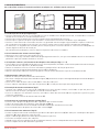
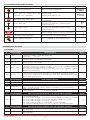
8. MANUAL DE USO E LIMPEZA PARA AMBIENTES ALIMENTARES
INDICAÇÕES GERAIS
A porta se destina ao uso em locais nos quais são preparados alimentos de acordo com o regulamento (CE)
NUM. 852/2004 sobre a higiene dos alimentos. Não é prevista a utilização como porta externa. A porta não é dotada de
isolamento térmico de modo a impedir a formação de condensação entre locais com forte diferença de temperatura.
As substâncias que estão sendo trabalhadas devem ser cobertas na parte superior durante a eventual passagem
através da porta.
LIMPEZA
Para a manutenção do nível de higiene correcto, recomenda-se a lavagem da porta com as frequências indicadas na tabela
a seguir.
Realize a limpeza da porta com dispositivos normalmente em uso em ambientes industriais alimentícios.
1. Temperatura máx da água de lavagem: 70 °C
3. Produtos:
2. Equipamentos:
- detergentes industriais espumosos e não espumosos
- utilize equipamentos com água sem pressão
- hipoclorito de sódio em solução diluída (água sanitária
- evite o uso de escovas de cerdas duras, que podem
25%)
estragar a superfície da estrutura
- amónio em solução diluída (amoníaco 25%)
- use equipamentos limpos
4. Secagem:
- panos limpos
- papel descartável
A advertência de usar água ou ar sem pressão foi feita a fim de evitar a difusão descontrolada de sujidade/resíduos
de comida no ambiente circundante
Frequência
recomendada
Partes / componentes
Modos
Diário
Superfícies externas na visão Após a lavagem, realize 4-5 manobras de abertura/fecho da porta
da estrutura.
para centrifugar a água presente na estrutura.
Limpe o interior da tampa do contentor passando um pano na borda
interna inferior.
Remova a borda inferior das colunas e seque com panos limpos as
placas de fecho do bolso por ambos os lados.
Zona de deslizamento da Limpe com a porta aberta
estrutura nas colunas.
Zona interna sob as tampas da Remova as tampas (1) para limpar e secar.
coluna (se presentes).
Limpe as abraçadeiras com uma escova, se houver.
Limpe os cabos com um pano sobre todo o comprimento.
Quadro electrónico.
Semanal
Após a lavagem e secagem externa do quadro, seque com panos
limpos a borda externa de fecho (2).
Interno dos cabeçotes sob as Remova as tampas (3) para limpar e secar.
Limpe a caixa de derivação com uma escova de cerdas macias
tampas.
Seque o interior dos cabeçotes com panos limpos.
Seque a caixa de derivação com panos limpos.
Interior da tampa do contentor Remova a tampa (4) para limpar e secar.
e rolo enrolador.
Os componentes desmontados para a limpeza devem ser remontados de modo a restaurar as condições iniciais.
4
2
3
1
0DT850 2015-05-08
- 20 -
PT
9. AMSES
+
01
X9
-
02
X9
88
1
2
90
X900
92
89
91
94
93
96
98
95
97
99
S
i3
i2
S
S
i4
V
12
1
3
5
K4
7
9
6
K5
K6
K7
8
11
13
10
15
12
17
14
19
16
21
18
23
20
25
22
27
24
29
26
31
Si3 Si4
K4 SINAL DE PORTA ACTIVA
+
Contacto
88 90 92
X901
Si1 Si212V
89 91 93
X902
94 96 98
95 97 99
-
88
N.A
90
C
92
N.F
T1
1
3
2
5
4
7
6
9 11 13 15 17 19 21 23 25 27 29 31
8 10 12 14 16 18 20 22 24 26 28 30 32
41 43 45 51 54
42 44 46 52 53
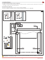
9.1 LIGAÇÃO FUNÇÃO INTERBLOQUEIO E AIRLOCK
Interligação
17
91 89
18
Porta A, mensagem E107 (terminal de ligação
18): a porta A está bloqueada na posição
FECHADA.
Airlock
24
20
96
94
PORTA A
Porta A, mensagem 3108 (terminal de ligação
20): a porta A recebe um comendo de abertura
da porta B.
Porta A, mensagem I130 (terminal de ligação 94
/ 96): a porta A envia um comando de abertura
à porta B.
W
Terminais de ligação 89/91: a porta A bloqueia
a porta B na posição FECHADA.
18
91 89
24
96
94
20
W: Interruptor de BLOQUEIO ON/OFF
PORTA B
- 21 -
0DT850 2015-05-08
0DT850 2015-05-08
- 22 -
LISTA DE COMPONENTES
PACKING LIST
Referência
Reference
Descrição
Description
Quantidade
Quantity
A
Placa de fixação (direita / esquerda)
Fixing plate (right / left)
2
B
Coluna (direita / esquerda)
Column (right / left)
2
C
Cabeçotes laterais
Lateral plate of the transom (right / left)
2
D
Main Shaft
Transom with rolled curtain
1
E
Acionamento manual (opcional)
Manual driving device (optional)
1
F
Haste de acionamento manual (opcional)
Manual driving rod (optional)
1
G
Tampa coluna (direita / esquerda)
Cover column (right / left)
2
H
Tampa cabeçotes laterais (direita / esquerda)
Cover Lateral plate of the transom (right / left)
2
I
Cobertura acionamento manual (opcional)
Cover manual device (optional)
1
L
Quadro eletrónico
Control unit
1
M
Caixa de acessórios
Hardware box
1
D
M
G
L
E
A
F
C
C
G
B
H
B
H
G
- 23 -
I
0DT850 2015-05-08
DESENHOS DA INSTALAÇÃO MECÂNICA
1
LT = PL + 335
100
100
2
372
100
355
L
1500
PH
L/2
max. 200
=
PL
=
Photocell
150
PL
150
143
6
6A
C
B
A
8
F
9
MECHANICAL INSTALLATION DRAWINGS
4
3
5
X=Y± 10mm
X
Y
50
7
E
D
L
G
I
I
M
H
G
H
10
CRITÉRIOS DE MONTAGEM ESPECÍFICOS PARA A HIGIENE DE AMBIENTES ALIMENTARES
SPECIFIC ASSEMBLY CRITERIA FOR THE HYGIENE OF FOOD ENVIRONMENTS
PT
Lacre as zonas destacadas, fechando o máximo
possível as bordas.
A remoção dos componentes não é prevista a não ser
por quebras que prevejam a completa substituição.
Em caso de substituição, realize a restauração da
impermeabilização dos componentes.
Pa ra a s o p e ra çõ e s d e i m p e r m e a b i l i z a çã o ,
recomendam-se selantes poliuretânicos como:
- SARATOGA FLEXEDIL 66
- MAPEI MAPEFLEX PU45
- BOSTIK EDILIZIA EXPRESS
EN
Seal the areas highlighted, bringing the edges as close
together as possible.
The removal of parts is not required, except for
problems which require complete replacement.
In case of replacement, the components should be
resealed.
For the sealing operations, we recommend
polyurethane sealants such as:
- SARATOGA FLEXEDIL 66
- MAPEI MAPEFLEX PU45
- BOSTIK EDILIZIA EXPRESS
PT
R3
3°
Instale o quadro electrónico inclinado com um ângulo
mínimo de 3°, para evitar o acúmulo de água na
superfície superior
Não monte prensa-cabos adicionais além daqueles
já instalados
Do not assemble any further cable glands apart from
those already installed.
0DT850 2015-05-08
- 26 -
Min.
10 cm
ON
OFF
EN
Install the electronic panel tilted at a minimum angle
of 3° to avoid water collecting on the upper surface
EN
- 27 -
0DT850 2015-05-08
CONTENTS
Chap.
1.
2.
3.
4.
Topic ........................................................................................................................................... Page
GENERAL SAFETY PRECAUTIONS ................................................................................................ 28
TECHNICAL CHARACTERISTICS ................................................................................................... 29
MECHANICAL INSTALLATION ....................................................................................................... 30
ELECTRIC CONNECTIONS
4.1 Connecting the control panel / motor / security ...................................................................... 31
4.2 Safety photocells ...................................................................................................................... 31
ELECTRONIC CONTROL PANEL 5QEX
5.1 Power and protection ............................................................................................................... 32
5.2 Motor and encoder connections ............................................................................................... 33
5.3 Input connections ..................................................................................................................... 34
5.4 Gopav connection and synchronization .................................................................................... 35
ADJUSTING AND STARTING
6.1 Pushbutton panel .................................................................................................................... 36
6.2 Limit-switch adjustment ......................................................................................................... 36
6.3 Fine adjustment of the closing position .................................................................................. 37
6.4 Fine adjustment of the opening position ................................................................................. 37
6.5 Programming closing time ...................................................................................................... 38
FAULTS AND SOLUTIONS
7.1 Functions ................................................................................................................................. 38
7.2 Overview of messages ............................................................................................................. 39
7.3 F.9xx internal system-dependent errors ................................................................................. 42
7.3.1 Information messages .......................................................................................................... 42
USER AND CLEANING MANUAL FOR FOOD ENVIRONMENTS...................................................... 46
AMSES ............................................................................................................................................ 47
9.1 Connection interlock and airlock function ............................................................................... 47
5.
6.
7.
8.
9.
1. GENERAL SAFETY PRECAUTIONS
This installation manual is intended for professionally competent personnel only.
The installation, the electrical connections and the settings must be completed in conformity with good workmanship
and with the laws in force.
Read the instructions carefully before beginning to install the product. Incorrect installation may be a source of danger.
Packaging materials (plastics, polystyrene, etc) must not be allowed to litter the environment and must be kept out of the
reach of children for whom they may be a source of danger.
Before beginning the installation check that the product is in perfect condition.
Do not install the product in explosive areas and atmospheres: the presence of flammable gas or fumes represents a serious
threat to safety.
Before installing the door, make all the structural modifications necessary in order to create safety clearance and to guard
or isolate all the compression, shearing, trapping and general danger areas.
Check that the existing structure has the necessary strength and stability.
The safety devices must protect against compression, shearing, trapping and general danger areas of the motorized door.
Display the signs required by law to identify danger areas.
Each installation must bear a visible indication of the data identifying the motorised door.
Before connecting to the mains check that the rating is correct for the destination power requirements.
A multipolar isolation switch with minimum contact gaps of 3 mm must be included in the mains supply.
Check that upstream of the electrical installation there is an adequate differential switch and a suitable circuit breaker.
Ensure that the motorised door has an earth terminal in compliance with the safety standards in force.
The manufacturer of the door declines all responsibility in cases where components which are incompatible with the safe
and correct operation of the product or whenever modifications of any nature are made that have not been specifically
authorised by the manufacturer.
For repairs or replacements of products only Entrematic Group AB original spare parts must be used.
The fitter must supply all information concerning the automatic, manual and emergency operation of the motorised door or
gate, and provide the user with the operating instructions.
Optional accessory
Top W
All rights reserved
$OOGDWDDQGVSHFL¿FDWLRQVKDYHEHHQGUDZQXSDQGFKHFNHGZLWKWKHJUHDWHVWFDUH7KHPDQXIDFWXUHUFDQQRWKRZHYHUWDNH
DQ\UHVSRQVLELOLW\IRUHYHQWXDOHUURUVRPLVVLRQVRULQFRPSOHWHGDWDGXHWRWHFKQLFDORULOOXVWUDWLYHIDFWRUV
0DT850 2015-05-08
- 28 -
EN
6
2
4
8
9
7
17
1
5
19
10
11
26
3
25
24
23
22
21
15
20
18
13
16
14
Ref.
1
2
3
4
5
6
7
8
9
10
11
12
13
12
Description
Lateral head plate(left)
Lateral head plate(right)
Slot for curtain reset (left)
Slot for curtain reset (right)
Left cover lateral plate
Right cover lateral plate
Gearmotor with encoder
Rolling shaft
Head cover
Manual driving device with rod and cover
Connection box
Safety edge transmitter (Top W)
Bottom edge with sand ballast
Ref.
14
15
16
17
18
19
20
21
22
23
24
25
26
Description
Fixing plate to the floor (left)
Fixing plate to the floor (right)
Column (left)
Column (right)
Column cover (left)
Column cover (right)
Electronic board
Safety photocell (Top W)
Polyester curtain
Curtain reinforcement pipe
transparent PVC window
Vertical reinforcing strip
Curtain reinforcement plates
2. TECHNICAL CHARACTERISTICS
Power supply voltage .......................... 230 V, 50/60 Hz
Power input ........................................................... 16 A
Auxiliary control power voltage ....................... 24V
Motor rating ..................................................... 0.75 KW
Control board protection class ............................. IP 54
Operating temperature ................................. - 5 + 50°C
Maximum relative humidity ........................... 80 ÷ 90%
The main supply must be selected referring to the indicated current absorption and also considering length and laying
of cables.
- 29 -
0DT850 2015-05-08
3. MECHANICAL INSTALLATION
See the relevant drawings of the mechanical installation at page. 24 - 25 (central sheet to be removed).
3.1 Checking the doorway (fig.1)
ƒ Check the size of the doorway and its correspondence with the dimensions of the door supplied, taking into account any
necessary clearances in the case of installation inside doorway.
ƒ Check that no existing structures obstruct the assembly of the door.
ƒ Ensure the existing surfaces are level and, if necessary, adapt them using appropriate shims.
ƒ Check the solidity of the opening: secure anchorage must be ensured by means of brackets or anchor plugs. In the case
of insufficient or dubious solidity, it is necessary to create an adequate self-supporting metal structure.
ƒ The materials and equipment used for fastening the door to the structure must have characteristics that are appropriate
for the hygiene standards of the installation site.
Upon completion of door installation, clean and sanitise the entire surrounding area.
3.2 Positioning vertical columns (fig.2)
ƒ Measure the doorway L and trace the middle axel: L/2.
ƒ Using the axis (L/2), centre the size of horizontal passageway PL, and mark the exact position of the uprights on the floor
at its ends.
3.3 Fixing the columns and positioning of the side plates (fig. 3 - 4 -5)
ƒ Fix the base plates on the marks or the column to the wall (cutting the column according to installation height) using
anchor bolts, size M8.
ƒ Plumb the vertical posts and secure them provisionally with clamping system.
ƒ Check the squareness of alignment by measuring the diagonals.
ƒ Mark the attachment of the side plates and prepare the fixing with anchor bolts, size M8.
3.4 Assembly of the heads (fig.6)
ƒ Fit the side plates to the winding shaft.
ƒ Align the mounting flange as shown in (fig. 6A), so that the mounting of the manual release remains properly aligned.
ƒ Pull out the cables (A) centrally.
ƒ Fix the left side using the three screws (B) and the right using a single screw (C).
3.5 Installation of winder shaft (fig.7)
ƒ Carefully lift the shaft by forklift or other suitable lifting system, making sure it does not fall during the handling and
protecting the fabric from damage.
ƒ Insert the end plates on the vertical uprights, sliding the cables of the photocells (D) in their seats, to avoid damage.
ƒ Fix the side plates (E) firmly.
3.6 Manual driving device, optional (fig.8)
ƒ Insert and secure the device (F) using the 4 screws.
ƒ Connect the safety micro-switch as shown on page 8.
ƒ Test the correct operation using the manual rod provided.
ƒ Insert the bottom edge of the curtain in the runners of the columns (fig.9).
3.7 Positioning the covering (fig.10)
ƒ Install the top cover of the winding shaft using the two pins on the rear (G) of the heads and secure using the two front pins
(H) and screws (I).
ƒ Route the cable into the photocell seat (L).
ƒ Position the side covers of the head plates.
ƒ In the case of a manual drive installation, insert the rubber cap (M).
ƒ Attach the side covers to the uprights (optional).
0DT850 2015-05-08
- 30 -
EN
4. ELECTRIC CONNECTIONS
4.1 Connecting the control panel / motor / security
ƒ Figure 11 shows the layout of the cables supplied, and their position in the door; each cable is identified by a special code
on an adhesive label.
4.2 Safety photocells
ƒ Wire the device as per the diagram (fig.11).
ƒ Make the connections in the control panel, as shown in the diagrams (par. 5.3)
11
SB
M
E
8553B
8568
M
F
M
E
8562
8638
OFF
ON
8553A
Tx
8553B
Rx
The main supply must be selected referring to the indicated current absorption and also considering length and laying
of cables.
- 31 -
0DT850 2015-05-08
5. ELECTRONIC CONTROL PANEL 5QEX
5.1 POWER AND PROTECTION
F1
F2
Si3 Si4
Si1 Si212V
F3
T1 T2 T3
PE
24 V
4
7
6
9 11 13 15 17 19 21 23 25 27 29 31
41 43 45 51 54
8 10 12 14 16 18 20 22 24 26 28 30 32
N N
42 44 46 53 53
ØV
L
Blue
Black
N
Blue
2
5
Black
3
Yellow-Green
1
X1
L1 L1
111
112
113
211
PE
212
L
N
311
312
L
N
313
L
N
230V AC
FUSES
ID
Value
F1
T 250 mA - L 250 V
F2
T 500 mA - L 250 V
F3
T 3.15 A - 230 V
0DT850 2015-05-08
- 32 -
EN
5.2 MOTOR AND ENCODER CONNECTIONS
Si3 Si4
Si1 Si212V
T1 T2 T3
PE
24 V
1
3
2
5
4
7
6
9 11 13 15 17 19 21 23 25 27 29 31
8 10 12 14 16 18 20 22 24 26 28 30 32
X1
L1 L1
41 43 45 51 54
N N
42 44 46 52 53
ØV
111
112
41 43 45
113
Door open
211
NO C NC
42 44 46
212
Door closed
311
NO C NC
White
Yellow
Green
Brown
Shielded
Free contacts max. 230V - 3A
Black U/L1
Black V/L2
Black W/L3
Yellow/Green
Black
White
312
L
N
313
LAMP
E
M
113
LK
N
INPUTS
REF
Output
Value
M
UWV
M
3~
Description
230 V~ / 10 A
Three-phase Motor
LK
230 V = 0,2 A
Solenoid parking brake
LAMP
230 V
Flashing light (optional)
INPUTS
REF
Output
Description
E
E
Absolute encoder
- 33 -
0DT850 2015-05-08
5.3 INPUT CONNECTIONS
Si4
Si1 Si212V
T1 T2 T3
PE
24 V
1
3
2
5
4
7
6
9 11 13 15 17 19 21 23 25 27 29 31
8 10 12 14 16 18 20 22 24 26 28 30 32
X1
L1 L1
41 43 45 51 54
N N
L
42 44 46 52 53
N
ØV
111
112
113
211
1
212
7
5
2
6
8
311
312
L
N
White
Red
Brown
Black
Blue
Close
Open
Stop
313
External commands
8562
Blue
Black
Blue
Brown
Black
White
Red
8638
8568
Blue
Black
Blue
Brown
8553A
4 3
Blue
Brown
Black
8553B
11 28
SB
12 11 28
Tx
Rx
SAFETY 1-2 (NC) External stop
Connection
Description
3
4
N.C
Micro-contact safety manual release
11
12
N.C
Safety photocells
COMMAND
Connection
Description
5
6
N.O
Opening command
7
8
N.O
Closing command
0DT850 2015-05-08
- 34 -
EN
5.4 GOPAV CONNECTION AND SYNCHRONIZATION
Si4
Si1 Si212V
T1 T2
8.2 kΩ
24 V
1
3
2
5
4
7
6
9 11 13 15 17 19 21 23 25 27 29 31
8 10 12 14 16 18 20 22 24 26 28 30 32
41 43 45 51 54
42 44 46 52 53
Access the GOPAVT device by removing the side
plate (B).
Caution: Remove the battery from the
mobile unit, before proceeding with the
configuration.
ØV
Power up the GOPAVR stationary unit , LED W
will flash normally and contact OUT1 will be
open;
ƒ insert the battery of the GOPAVT mobile unit
in the seat, all LEDs on the handset flash;
ƒ press the (A) button on GOPAVR stationary
unit: stationary unit LED W will be illuminated
and LED OC will flash;
ƒ press the (A) button on the GOPAVT mobile
unit , the LEDs of the mobile unit and the
stationary unit will turn off;
ƒ Check the correct configuration by activating
the safety edge and checking LED W on the
GOPAVR stationary unit, and LED IN.
A
IN1
GOPAVR
OUT1
SC
OC
W
0 1
B
GOPAVT
IN2
IN1
SC
OC
A
- 35 -
0DT850 2015-05-08
6. ADJUSTING AND STARTING
6.1 PUSHBUTTON PANEL
Starts the opening operation.
Starts the closing operation.
ON
S1
Activates and deactivates the STOP
operation.
Emergency button
Main switch
OFF
ON
6.2 LIMIT-SWITCH ADJUSTMENT
COMMAND
OFF
FUNCTION
Main switch OFF
Main supply = 0FF
Set the dip-switch S1 to ON
Parameter programming
Main switch ON
Activating control
Push the Emergency button
Enable programming
DISPLAY
ON
S1
ON
“Open” or “Close”
Parameter searching P.210:
Search parameters to set. The parameters
limit-switch calibration
aren’t all in view.
“Stop” short press
“Open”
“Stop” long press
View parameter content
Increase the original value
Decimal points flash when the value is changed
Save the new value
Hold until the decimal points stop flashing
“Stop” short press
Back to parameter view
Pull Emergency button
Access to the limit-switch calibration mode
“Stop” short press
Closing limit-switch adjustment activated
3
3
3
>$O
( (9
Check the direction of the motor (“open”/”close”). If wrong go to parameter 3 and modify the direction of motor rotation, changing
the value from to “Close”
Closing command for "dead-man" operation, until
"door closed" position
“Stop” long press
Saves the “door closed” position
The system will launch automatically
Enable opening limit switch adjustment
“Open”
Opening command for "dead-man" operation, until
"door open" position
“Stop” long press
Save the “door closed” position
The system will launch automatically
Enable intermediate limit switch adjustment
“Close”
Closing command for "dead-man" operation, until
"intermediate" position
Press the "Stop" button (long press)
Save the intermediate position
0DT850 2015-05-08
- 36 -
(
(
(
(
(
(
(
(
(9
(9
(R
(R
(R
(,
(,
(,
EN
6.3 FINE ADJUSTMENT OF THE CLOSING POSITION
COMMAND
OFF
FUNCTION
DISPLAY
Main switch OFF
Main supply = 0FF
Set the dip-switch S1 to ON
Parameter programming
Main switch ON
Main supply = ON
Push the Emergency button
Enable programming
3
“Open” or “Close”
Search parameters to set
Search P.221:
fine adjustment of the closing position
3
“Stop” short press
View parameter content
ON
S1
ON
A greater value stops closure in a higher position; a
“Open” (towards positive) or “Close” (towards
lower value stops closure in a lower position. E.g. At -3,
negative) to adjust value correction
the closing point is closer towards the ground.
“Stop” long press
Saves the new value
Hold until the decimal points stop flashing
“Stop” short press
Back to parameter view
Pull Emergency button
Standard functioning
Open and close the door
Verify the correct positioning of the opening point
*
3
6.4 FINE ADJUSTMENT OF THE OPENING POSITION
COMMAND
OFF
FUNCTION
DISPLAY
Main switch OFF
Main supply = 0FF
Set the dip-switch S1 to ON
Parameter programming
Main switch ON
Main supply = ON
Push the Emergency button
Enable programming
3
“Open” or “Close”
Search parameters to set
Search P.231:
fine adjustment of the opening position
3
“Stop” short press
View parameter content
ON
S1
ON
A greater value stops closure in a higher position; a
“Open” (towards positive) or “Close” (towards
lower value stops closure in a lower position. E.g. At -3,
negative) to adjust value correction
the closing point is closer towards the ground.
“Stop” long press
Save the new value
Hold until the decimal points stop flashing
“Stop” short press
Back to parameter view
Pull Emergency button
Standard functioning
Open and close the door
Verify the correct positioning of the opening point
- 37 -
*
3
0DT850 2015-05-08
6.5 PROGRAMMING CLOSING TIME
COMMAND
FUNCTION
DISPLAY
Push the Emergency button
Enable programming
3
“Open” or “Close”
Search parameters to set
Search P.010:
Set the closing time
3
“Stop” short press
View parameter (default value)
“Open”
“Close”
“Stop” long press
“Stop” short press
Pull Emergency button
Increase the closing time
The decimal points will flash if the current value is
changed.
Decrease the closing time
The decimal points will flash if the current value is
changed.
Save the new value
Hold until the decimal points stop flashing
Cancels the “set parameters” mode.
The default value will again be displayed.
*
*
Standard functioning
7. FAULTS AND SOLUTIONS
7.1 FUNCTIONS
P.
(Unit) range
000
(Cycles)
010
(s) 0….200
011
(s) 0….200
020
(ms) 0….1000
025
(s) 0….20
P
100
101
102
(Unit) range
(Hz) 30…200
(A) 0…9.9
(% ) 40…100
103
(V) 100…500
130
0...1
P
210
P
(Unit) range
0….5
(Unit) range
221
(Ink) ± 125
231
(Ink) ± 60
0DT850 2015-05-08
Door functions
Door cycle counter display
Display: 1234567 → 1234. ź -press .567
Display:
67 → 67
Open hold time (End position Upper – Eo)
0 = automatic closing deactivated.
Open hold time (intermediate stop – E1)
0: Automatic closing deactivated
Pre-warning time before open
Following receipt of an OPEN command, opening is delayed by the time specified in this
parameter.
Attention! If you want to set a pre-warning to 4 seconds, then modify parameter P.020 to
400
Pre-warning time before close.
The closing move is delayed following receipt of a CLOSE command or after expiration
of the auto close time (forced close) by the time specified in this parameter.
Default
Nominal motor data
Motor rated frequency (see nameplate, note: Y/Δ)
Motor rated current (see nameplate, note: Y/Δ)
Power factor cosM (see nameplate: cos M: 0.63 →63)
Motor rated voltage (see nameplate, note: Y/Δ). The motor characteristics curve is
automatically calculated based on the rated frequency and nominal voltage.
Motor rotational field
0: Right rotating
1: Left rotating
Default
-1
-1
-1
Indicating the end positions with electronic limit switches
Selecting the position calibrated in dead-man mode (“teach in”):
0: no → None/Cancel
1: Eu → Upper and Lower limit switch (intermediate stop: see P244)
2: Eo → Upper limit switch (intermediate stop: see P244)
3: uo → Upper and Lower limit switch
4: E1 → Intermediate stop limit switch (P244 is ignored)
5: al → (all) Lower, Upper and Intermediate Stop limit switch (P244)
Default
Correcting end positions with electronic limit switches
Correction value for Lower end position
(set to 0 after new calibration).
Correction value for Upper end position
(set to 0 after new calibration).
Default
- 38 -
4
10
0
0
-1
1
O
O
O
EN
P
910
920
(Unit)
range
0…15
Eb1
Eb2
Eb3
Eb4
Ebcl
Eb
925
930
940
{s} 0….120,0
{V}
980
0….2
Diagnostics
Default
Selecting display mode (request using STOP button or during motor movement)
0: Controller sequence (automatic mode)
1: {Hz} Current rotary field frequency
2: {A} Motor current (> 1A)
3: {V} Motor current
4: {A} Link current (effective current)
5: {V} Link voltage
6: {°C} End temperature in °C
7: {°F} End temperature in °F
8: Last measured run time (1/10 t/m 99.9s, 1/1 from 100s)
For electronic limit switches only:
9: [Inc] current position progress
10: [Inc] current reference position
11: [dig] current channel 1 value of absolute encoder
12: [dig] current channel 2 value of absolute encoder
13: [dig] current reference voltage (2.5V)
14: Temperature in housing in (°C)
15: Temperature in housing in (°F)
Display error memory/faults
Open by pressing Stop key again
Activate/ deactivate by pressing Open/Close key
Quit by pressing Stop key.
Close the operation cancelling “EB-“
ǩ(EǵHUURUPHVVDJHVPRVWUHFHQWRU (U
ǩ(EǵHUURUPHVVDJHV
(U
ǩ(EǵHUURUPHVVDJHV
(U
ǩ(EǵHUURUPHVVDJHV
(U
ǩ(EFOǵFOHDUHQWLUHHUURUPHPRU\
ǩ(Eǵ&DQFHO
(Display noEr: no error).
Software version display
Motor run-time during last door movement
Line supply voltage display
Service mode
0: Automatic (open and close in hold function)
1: Dead-man close (manual mode close / automatic mode open)
2: Dead man (manual mode for open and close)
3: Emergency (dead-man open and close; all errors and security functions are ignored)
O
Eb 1
0
7.2 OVERVIEW OF MESSAGES
F.000
Door position too high
F.005
Door position too low
F.020
F.030
F.031
F.043
Incorrect end positions
Value for upper emergency limit switch too low Upper limit switch range (limit
switch band) too low. Mechanical brake defective or improperly set.
Value for lower emergency limit switch too low. Lower limit switch range
(limit switch band) too low. Mechanical brake defective or improperly set.
Inaccuracies related to door movements
- Current motor operating time has exceeded the set maximum operating
time; the door may not run smoothly or may be blocked.
Operating time exceeded (during
opening, closing or dead-man -mode) - One of the end stops has not been activated when mechanical end stops are
used.
- The door or motor is blocked
- Output too low for the required torque
- Speed too low
Dragging errors (the position set for
- Attachment to the shaft of the absolute value detector or the increase
the door has not been reached)
detector is not secure
- Incorrect position system in use (P.205).
- When increase detector is used: Channel A and B have been swapped
The registered turning direction
- Motor rotation direction was changed during calibration
does not match the expected turning
- Too much "sagging" at start-up, brakes start too early or the torque is
direction
insufficient; adjust the voltage if required
Fault with the front end stop of the
- The front end stop for the light bar is in the centre and upper end position.
light bar
- 39 -
0DT850 2015-05-08
F.050
F.051
F.052
F.090
Error message from the increase detector
- Reference stop is activated each time (defective).
Position of the reference stop is not
- Reference stop is activated too far from the selected reference.
within the acceptable range during
- Reference stop is activated by the belt of the end stop.
cyclic synchronisation.
- P270 and P280 are both on the reference stop.
- Reference stop is located by the belt of the end stop.
Position of the reference stop is not
- Reference stop is located outside 15% EO.
within the acceptable range.
- Reference stop is defective.
- During the synchronisation after activation, the reference stop is not found
Reference stop is not recognized.
to be within 20% EO.
- The reference stop is not found to be in the end position.
Parameter not set
Parameters have not been allocated to The basic parameters (P.205, P.100 to P.103) of the TST FUE control have not
the control.
yet been set.
F.201
Internal E stop "push button” tripped
or Watchdog
(computer monitor).
F.211
F.212
External E-stop 1 tripped.
External E-stop 2 tripped.
Safety chain faults
E-stop chain was interrupted at input of “internal E-stop” without parametersetting mode having been selected. Internal parameter or EEPROM checks
defective, pressing the STOP key provides additional information about the
cause.
The E-stop chain was interrupted at input 1. (terminals 1 and 2)
The E-stop chain was interrupted at input 2. (terminals 3 and 4)
Safety chain faults
F.360
Short circuit detected on guard input
F.362
F.363
F.364
F.365
F.369
F.374
F.385
F.400
F.410
F.420
F.430
F.435
F.440
F.510
F.511
Short circuit detected on guards with normally closed contact
One of the processing channels for short circuit detection does not react
Redundancy error with short circuit
identically with the second channel.→ Control board defective
Connection cable defective or not connected
Interruption on guard input
Termination resistor incorrect or missing
Jumper J600 incorrectly set
Safety edge was not activated as expected when requesting a test.
Safety edge testing failed
The time between request for testing and actual testing did not match
One of the processing channels for interruption detection does not react
Redundancy error with interruption
identically to the second channel.
→ Control board defective
Internal safety edge incorrectly set up An internal safety edge is connected but deactivated
Pre-limit switch for safety edge incorrectly set or defective
Safety bar testing failed
Processing module defective
Safety edge defective
Pre-limit switch for turning off the safety edge or reversing after safety edge
Fault in pre-limit switch for safety edge
tripping remains tripped even in the upper end position.
ǩ([FHVVLYHQRLVHRQVXSSO\YROWDJH
Controller hardware reset detected
ǩ,QWHUQDOZDWFKGRJWULSSHG
ǩ5$0(UURU
ǩ:URQJPRWRUGDWDVHW3Ǟ3
ǩ1RQDGMXVWHGYROWDJHLQFUHDVHERRVWVHW3RU3
Over-current (motor current or
ǩ0RWRUQRWSURSHUO\VL]HGIRUGRRU
intermediate circuit)
ǩ'RRUVWLFNV
ǩ%UDNHFKRSSHULQWHUIHUHQFHGHIHFWLYHPLVVLQJ
ǩ)HHGYROWDJHIDUWRRKLJK
Overvoltage in intermediate circuit
ǩ0RWRUIHHGVEDFNWRRPXFKHQHUJ\LQJHQHUDWRUPRGHGRRUPRWLRQHQHUJ\
Limit 1
cannot be sufficiently reduced
ǩ([FHVVLYHORDGRQȌQDOVWDJHVRUEUDNHFKRSSHU
Temperature cooler outside of working
ǩ$PELHQWWHPSHUDWXUHWRRORZIRUFRQWUROOHURSHUDWLRQ
range Limit 1
ǩ&ORFNIUHTXHQF\RIȌQDOVWDJHWRRKLJK3DUDPHWHU3
Fault: Temperature in housing rises
ǩ([FHVVLYHORDGRQIUHTXHQF\FRQYHUWHUFLUFXLW
over 75°C
ǩ&RQWUROOHUFDELQHWLQVXIȌFLHQWO\FRROHG
ǩ%RRVWQRWDGMXVWHG
Overcurrent in intermediate circuit
ǩ0RWRULQFRUUHFWO\VL]HGIRUGRRU
Limit 1
ǩ'RRUVWLFNV
ǩ:URQJPRWRUGDWDVHW3Ǟ3
ǩ1RQDGMXVWHGYROWDJHLQFUHDVHERRVWVHW3RU3
Motor / intermediate circuit
ǩ0RWRUQRWSURSHUO\VL]HGIRUGRRU
overcurrent Limit 2
ǩ'RRUVWLFNV
ǩ&KHFNSDUDPHWHU3WR3
Pb with injection of current for braking
ǩ7U\WRUHGXFH3DQG3
0DT850 2015-05-08
- 40 -
F.515
F.519
F.520
F.521
F.524
F.530
F.535
F.540
F.700
F.720
F.750
F.751
F.752
F.760
F.761
F.762
EN
ǩ,QFRUUHFWPRWRUFXUYHPRWRUUDWHGFXUUHQWVHW3
ǩ7RRPXFKERRVW3RU3
ǩ0RWRULQFRUUHFWO\VL]HG
ǩ6KRUWFLUFXLWRUJURXQGIDXOWRQPRWRUWHUPLQDOV
ǩ0RWRUUDWHGFXUUHQWVHWWLQJLVLQFRUUHFW3
ǩ7RRPXFKERRVW3RU3
IGBT driver chip detected overcurrent
ǩ0RWRULQFRUUHFWO\VL]HG
ǩ0RWRUZLQGLQJGHIHFWLYH
ǩ0RPHQWDU\EUHDNLQJRIWKH(6WRSFLUFXLW
ǩ%UDNHFKRSSHULQWHUIHUHQFHGHIHFWLYHPLVVLQJ
ǩ)HHGYROWDJHIDUWRRKLJK
Overvoltage in intermediate circuit
ǩ0RWRUIHHGVEDFNWRRPXFKHQHUJ\LQJHQHUDWRUPRGHGRRUPRWLRQHQHUJ\
Limit 2
cannot be sufficiently reduced
ǩ,QSXWYROWDJHVXSSO\WRRORZXVXDOO\DWORDG
Overvoltage in intermediate circuit
ǩ/RDGWRRJUHDWȌQDOVWDJHRUEUDNHFKRSSHUIDXOW
ǩ2YHUORDGEXWQRVKRUWFLUFXLW
Ext. 24 V supply missing or too low
ǩ:KHQb9LVVKRUWHGWKHFRQWUROOHUYROWDJHGRHVQRWUDPSXSDQGJORZODPS
V306 comes on.
ǩ([FHVVLYHORDGRQȌQDOVWDJHVRUEUDNHFKRSSHU
Temperature cooler outside of working
ǩ$PELHQWWHPSHUDWXUHWRRORZIRUFRQWUROOHURSHUDWLRQ
range Limit 1
ǩ&ORFNIUHTXHQF\RIȌQDOVWDJHWRRKLJK3DUDPHWHU3
Fault: Temperature in housing rises
ǩ,QWHUQDOWHPSHUDWXUHWRRKLJK
over critical 80°C
ǩ%RRVWQRWDGMXVWHG
Overcurrent in intermediate circuit
ǩ0RWRULQFRUUHFWO\VL]HGIRUGRRU
Limit 2
ǩ'RRUVWLFNV
For electronic limit switches:
ǩ$IWHULQYRNLQJDFWLYDWLRQRIWKHIDFWRU\SDUDPHWHUV3DUDPHWHU3WKH
corresponding positioning system was not set up.
Position sensing defective
ǩ&DOLEUDWLRQQRWFRPSOHWHGRULVLQFRUUHFWDQGPXVWEHUHSHDWHG
ǩ:KHQDFWLYDWLQJWKHLQWHUPHGLDWHVWRSWKLVFRPPDQGLVLPSODXVLEOH
ǩ6\QFKURQL]DWLRQQRWȌQLVKHGRUUHIHUHQFHVZLWFKGHIHFWLYH
ǩ,QWHUPHGLDWHVWRSSRVLWLRQLVORZHUWKDQWKHPLQLPXPLQFUHPHQWDOYDOXH
(25).
ǩ6\QFKURQL]DWLRQZDVQRWȌQLVKHG
Synchronization error in position
ǩ7KHVHOHFWHGUHIHUHQFHVZLWFKZDVQRWUHDFKHGRULVRXWVLGHLWVWROHUDQFH
sensing with encoder
ǩ7KHLQFUHPHQWDOHQFRGHULVQRWFRXQWLQJRUWKHGRRULVEORFNHGDOVR)
lag error)
ǩ,QFUHPHQWDOLQSXWV,1DQG,1DUHUHYHUVHGDOVR)URWDWLRQHUURU
Protocol
ǩ'HIHFWLYHKDUGZDUHRUHOHFWULFDOO\QRLV\HQYLURQPHQW
Transmission error
Synchronization FU <-> absolute
ǩ'HIHFWLYHKDUGZDUHRUHOHFWULFDOO\QRLV\HQYLURQPHQW
encoder
ǩ$EVROXWHHQFRGHUSURFHVVRUHOHFWURQLFVGHIHFWLYH
ǩ,QWHUIDFHFDEOHGHIHFWLYHLQWHUUXSWHG
Timeout with
ǩ$EVROXWHHQFRGHUSURFHVVRUHOHFWURQLFVGHIHFWLYH
protocol transmission
ǩ'HIHFWLYHKDUGZDUHRUHOHFWULFDOO\QRLV\HQYLURQPHQW
ǩ3RVLWLRQHQFRGHUGULYHGHIHFWLYH
Position outside of window
ǩ$EVROXWHHQFRGHUSURFHVVLQJHOHFWURQLFVGHIHFWLYH
ǩ'HIHFWLYHKDUGZDUHRUHOHFWULFDOO\QRLV\HQYLURQPHQW
Distance Channel 1 <-> Channel 2
ǩ3RVLWLRQHQFRGHUGULYHGHIHFWLYH
outside allowed window
ǩ'HIHFWLYHKDUGZDUHRUHOHFWULFDOO\QRLV\HQYLURQPHQW
ǩ8SSHUOLPLWVZLWFK(RRULQWHUPHGLDWHOLPLWVZLWFK(KDVH[FHHGHGWKHYDOLG
limit range
Electronic limit switch positions
ǩ&RQWUROOHUQRW\HWLQLWLDOL]HG
incorrect
ǩ3RVLWLRQYDOXHVGXULQJFDOLEUDWLRQQRWFRUUHFWRUYDOXHVDUHQRORQJHU
plausible
Motor protection function detected
overcurrent
- 41 -
0DT850 2015-05-08
7.3 F.9XX INTERNAL SYSTEM-DEPENDENT ERRORS
Parameter not set
Internal errors that can still be resolved by the user are involved with this type of error.
When such an error occurs, contact customer service immediately.
7.3.1 INFORMATION MESSAGES
STOP
_Eu_
{Eu{
ZUF°
-Eo{Eo{
°AUF
-E1{E1{
FAIL
CALI/EICH
{NA{
NOTF
'Hd'
ParA
SYNC
'Au'
'Hc'
FUS
E.i.E.u.
E.i.E.o.
E.i.E.1.
General messages
Stop / Reset status, wait for next incoming command.
Lower end position Eu
Lower end position locked → no raising possible (e.g., lock-door)
Closing active
Upper End position Eo.
Upper end position locked → no closing possible (e.g., safety edge).
Opening active.
Middle end position E1 (intermediate stop position)
Middle end position locked → no closing possible (e.g., safety edge)
Fault → only dead-man travel is possible, possibly automatic opening
Calibration → setting the end positions in dead-man travel
(for absolute encoder) → start procedure using STOP key.
E-Stop → No travel possible, hardware safety chain interrupted.
E-travel → Dead-man travel without safety precautions, etc.
Manual → Dead-man mode.
Setting parameters
Synchronization (incremental encoder/limit switch → pos. unknown).
Automatic → indicates change from “Manual” to “Automatic” status
Semi-automatic → indicates change from “Manual” to “Semi-automatic”.
Initial display after power up. (Power Up and self-test)
Status messages during calibration
Calibration of the Lower end position requested (in dead-man mode).
Calibration of the Upper end position requested (in dead-man mode).
Calibration of the E1 intermediate position (in dead-man mode).
S.y.c{
Status messages during synchronisation
Synchronization of Lower end position requested
(dead-man mode or waiting for start)
Synchronisation of Upper end position requested
(dead-man mode or waiting for start)
Synchronisation of intermediate stop position E1 (in dead-man mode)
Automatic open until mechanical stop, then automatic synchronization of Upper end position
Automatic close taking into account safety devices until mechanical stop, then automatic
synchronization of Lower end position
Automatic close is locked due to request A
Hd.cL
Hd.on
Hd.Eu
Hd.Eo
Hd.Ao
Status messages during dead-man mode
Dead-man use when closing (membrane button: CLOSE).
Dead-man use when opening (membrane button: OPEN).
End position below range; dead-man use when closing no longer possible.
End position above range; dead-man use when opening no longer possible.
Outside the allowed Eo position (dead-man use not possible when opening).
I.080
I.100
I.150
I.160
Information messages during automatic use
Maintenance required soon / service counter nearly expired.
Speed when reaching upper end position too high.
Speed when reaching lower end position too high.
Door CLOSED still active
S.y.E.u.
S.y.E.o.
S.y.E.1.
S.y.op
S.y.Cl
0DT850 2015-05-08
- 42 -
EN
I.170
I.199
I.200
I.201
I.202
I.203
I.205
I.210
I.211
I.310
I.500
I.501
I.502
I.505
I.506
I.507
I.510
I.515
I.555
Forced opening in progress.
Door cycle not plausible (re-initialize → Parameters)
Reference position corrected or recognized (after calibration).
Reference position re-initialized.
Reference position missing.
Reference position incorrect.
Synchronization.
Upper pre-limit switch not plausible.
Lower pre-limit switch not plausible.
Open command on Door 2 being issued (AIRLOCK)
Correction of upper limit switch running
Upper pre-limit switch corrected
Upper limit switch band corrected
Correction of lower limit switch running.
Lower pre-limit switch corrected
Lower limit switch band corrected
Limit switch correction finished
Controller is preparing automatic teach-in of the limit switches
Limit switches being corrected
noEr
Er-Prog
Information messages during parameter allocation
Memory error: an error will not be saved.
Memory error: could not find the corresponding message for the error.
Programming message when the original parameter or default setting was being executed.
E.000
E.050
E.090
E.101
E.102
E.103
E.104
E.105
E.106
E.107
E.108
E.109
E.110
E.132
General inputs
Open membrane button.
Stop membrane button.
Close membrane button.
Input 1 / terminal 6
Input 2 / terminal 8
Input 3 / terminal 10
Input 4 / terminal 12
Input 5 / terminal 14
Input 6 / terminal 16
Input 7 / terminal 18
Input 8 / terminal 20
Input 9 / terminal 22
Input 10 / terminal 24
Check whether PA32 has a value of 0.
E.201
E.211
E.212
Safety range emergency range
Internal Emergency OFF button activated.
External Emergency stop 1 activated.
External Emergency stop 2 activated.
E.360
E.363
E.370
E.373
E.379
General aspects of detector
Activation of internal safety edge.
Fault in internal safety edge
Activation of external safety edge.
Fault in external safety edge.
External safety edge activated but not yet connected.
E.501
E.502
Detector channel 1
Detector channel 2
E.900
Internal inputs
Error signal of the drive module.
Induction loop processor plug-in module
- 43 -
0DT850 2015-05-08
APPLICATIONS
Use: 5 (minimum 5 years of working life with 600 cycles a day)
Applications: HEAVY DUTY (for industrial and commercial access with heavy-duty use).
ǩ Service class, running times, and the number of consecutive cycles are to be taken as purely indicative having been
statistically determined under average operating conditions, and cannot therefore be applied to specific cases. This refers
to the period when the product functions without the need for any extraordinary maintenance.
ǩ Independent variables such as friction, balancing and environmental factors may substantially alter the lifespan or
performance characteristics of the automatic access or parts thereof (including the automation systems). It is the
responsibility of the installer to adopt suitable safety measures for each single installation.
DECLARATION OF CONFORMITY
We:
Entrematic Group AB
Lodjursgatan 10
SE-261 44 Landskrona
Sweden
declare under our sole responsibility that the type of equipment with name / description:
ALIMAX
Roll-up rapid door without counterbalance
with performance levels as declared in the accompanying Declaration of Performance and the product label, and electrical
drive unit as identified in the log book provided , is in compliance with the following directives:
2006/42/EC
2004/108/EC
Machinery Directive (MD)
ElectroMagnetic Compatibility Directive (EMCD)
Harmonized European standards which have been applied:
EN 13241-1 EN 61000-6-2 EN 61000-6-3 EN 60335-1 EN 60204-1
Other standards or technical specifications, which have been applied:
EN 60335-2-103
EC type examination or certificate issued by a notified or competent body (for full address, please contact Entrematic Group
AB) concerning the equipment:
CSI Spa Reg. - N° 0497
Certificate Nr.: 0005\DC\POR\13
The manufacturing process ensures the compliance of the equipment with the technical file. The manufacturing process is
regularly accessed by a 3rd party.
Compilation of technical file:
Marco Pietro Zini
Entrematic Group AB
Lodjursgatan 10
SE-261 44 Landskrona
Sweden
Place
Landskrona
0DT850 2015-05-08
Email: [email protected]
Date
2013-07-01
Signature
Marco Pietro Zini
- 44 -
Position
President Entrance Automation
EN
USE INSTRUCTIONS
GENERAL SAFETY PRECAUTIONS
This user handbook is an integral and essential part of the product and must be delivered to the user. Keep
this document and pass it on to any future users.
This automation is a “vertical-roll door”; it must be used for the specific purpose for which it was designed.
Any other use is to be considered inappropriate and therefore dangerous. Entrematic Group AB declines all
responsibility for damage caused by improper, incorrect or unreasonable use.
USAGE PRECAUTIONS
ƒ Do not enter the door action area while the door is moving.
ƒ In the event of a fault or malfunction, turn off the main switch. The operations of maintenance, adjustment
and repair must be carried out by skilled and authorised staff.
ƒ Each automation has its own “Installation and Maintenance handbook”, detailing the periodic maintenance
plan. Please take care to check all the safety devices.
BUTTONS
ƒ Full opening: the door opens completely. The stroke can be fixed via the end stop microswitch.
ƒ STOP: the door stops immediately.
OPTIONAL DS - MANUAL OPERATION
ƒ To manually raise the curtain in the event of a power failure or fault, raise the curtain to the “open door”
position, as shown.
'R QRW OHDYH WKH PDQXDO URG
KDQJLQJDWWKHULQJGXULQJQRUPDO
RSHUDWLRQ RI WKH GRRU 8VH WKH
SURSHUFOLSVIRUZDOOPRXQWLQJ
ON
OFF
DETACH AND DELIVER TO THE CUSTOMER
ƒ Closing: the door closes completely. The stroke can be fixed via the end stop microswitch.
Close
Open
Installer:
Entrematic Group AB
Lodjursgatan 10
SE-261 44, Landskrona
Sweden
www.ditecentrematic.com
- 45 -
0DT850 2015-05-08
8. USER AND CLEANING MANUAL FOR FOOD ENVIRONMENTS
GENERAL INSTRUCTIONS
The door is intended for use in premises where food products are prepared in accordance with Regulation (CE)
NO. 852/2004 on food-product hygiene.
It is not intended for use as an exterior door.
The door does not have thermal insulation capable of preventing condensation from developing between rooms with a
marked difference in temperature.
The substances being processed must be covered when passing through the door.
CLEANING
To maintain the correct level of hygiene, we recommend washing the door as detailed in the following table.
Clean the door with the usual equipment in use in industrial food environments.
1. Max temperature of the washing water: 70°C
2. Equipment:
- use equipment with non-pressurised water
- do not use brushes with hard bristles, which could damage
the surface of the structure/door section
- use clean equipment
3. Products:
- foam and non-foam industrial detergents
- diluted sodium hypochlorite (bleach 25%)
- diluted ammonium (ammonia 25%)
4. Drying:
- clean cloths
- disposable paper
The instruction to use non-pressurised water or air aims to avoid the uncontrolled dispersion of dirt/food residue
in the surrounding area.
Recommended frequency Parts/components
Daily
Methods
Visible exterior surfaces of After washing, open/close the door 4-5 times to swill the water on
the curtain and the structure. the curtain.
Clean the inside of the casing cover by passing a cloth over the lower
inner edge.
Pull out the lower edge from the columns and dry the pocket closing
plates from both sides with clean cloths.
Curtain sliding area in the Clean with the door open
columns.
Inner area under the column Remove the covers (1) for cleaning and drying.
covers (if present).
Clean with a brush the cable ties if present.
Clean cables with a cloth over the entire length.
Electronic panel.
Weekly
After washing and drying the exterior of the panel, dry the outer
closing edge (2) with clean cloths.
Inside heads under the Remove the covers (3) for cleaning and drying.
covers.
Clean the connector block using a brush with soft bristles
Dry inside the heads with clean cloths.
Dry the connector box with clean cloths.
Inside casing cover and Remove the cover (4) for cleaning and drying.
winding roller.
The components removed for cleaning must be reassembled so as to restore the initial conditions.
4
2
3
1
0DT850 2015-05-08
- 46 -
EN
9. AMSES
+
01
X9
-
02
X9
88
1
2
90
X900
92
89
91
94
93
96
98
95
97
99
S
i3
i2
S
S
i4
V
12
1
3
5
K4
7
9
6
K5
K6
K7
8
11
13
10
15
12
17
14
19
16
21
18
23
20
25
22
27
24
29
26
31
Si3 Si4
K4 ACTIVE DOOR SIGNAL
+
Connection
88 90 92
X901
Si1 Si212V
89 91 93
X902
94 96 98
95 97 99
-
88
N.O
90
C
92
N.C
T1
1
3
2
5
4
7
6
9 11 13 15 17 19 21 23 25 27 29 31
8 10 12 14 16 18 20 22 24 26 28 30 32
41 43 45 51 54
42 44 46 52 53
9.1 CONNECTION INTERLOCK AND AIRLOCK FUNCTION
interlock
17
91 89
Door A, message E107 (connection terminal
18): Door A is locked in CLOSED position.
Airlock
18
24
20
96
94
Door A, message E108 (connection terminal
20): Door A receives an open command from
Door B.
Door A
Door A, message I130 (connection terminal 94 /
96): Door A sends an open command to door B.
W
Connection terminals 89/91: Door A locks Door
B in the CLOSED position.
W: AIRLOCK ON/OFF switch
18
91 89
24
96
94
20
Door B
- 47 -
0DT850 2015-05-08
0DT850 - 2015-05-08
Entrematic Group AB
Lodjursgatan 10
SE-261 44, Landskrona
Sweden
www.ditecentrematic.com