1
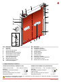
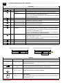
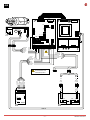
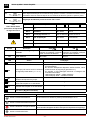
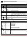
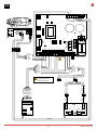
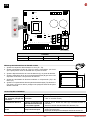
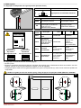
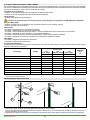
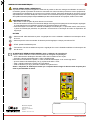
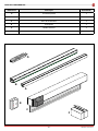
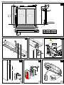
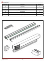
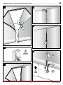
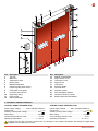
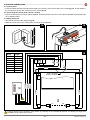
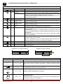
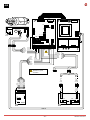
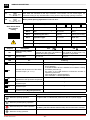
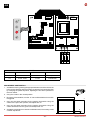
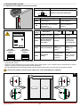
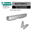
Ditec Sector Reset
0DT848
rev. 2015-05-27
Manual de instalação, manutenção, uso.
PT
Installation manual, maintenance, use.
EN
(Instruções originais)
(Original instructions)
www.ditecentrematic.com
ÍNDICE DOS ASSUNTOS
Cap.Assunto .................................................................................................................................. Pág.
1.
CARACTERÍSTICAS TÉCNICAS ................................................................................................ 2
2.
AVISOS GERAIS PARA A SEGURANÇA .................................................................................... 3
3. INSTALAÇÃO MECÂNICA
3.1 Verificações do vão de passagem........................................................................................... 4
3.2 Fixação das colunas verticais.................................................................................................. 4
3.3 Montagem da travessa............................................................................................................ 4
3.4 Montagem dos contrapesos..................................................................................................... 4
3.5 Instalação das fotocélulas........................................................................................................ 4
3.6 Montagem da alavanca de desbloqueio de emergência......................................................... 4
3.7 Instalação do dispositivo de segurança SLEC (Encoder linear).............................................. 4
3.8 Posicionamento da tela............................................................................................................ 4
4. ELÉCTRICAS CABLAGENS
4.1 Quadro eléctrico....................................................................................................................... 5
4.2 Ligações do quadro elétrico / motor / seguranças................................................................... 5
4.3 Fotocélulas de segurança........................................................................................................ 5
5.
QUADRO ELECTRÓNICO
5.1 49E - ligações.......................................................................................................................... 6
5.2 47E (inverter) - ligações......................................................................................................... 10
6.
REGULAÇÕES E ARRANQUE
6.1 Regulação do dispositivo de segurança SLEC (Encoder linear)........................................... 14
6.2 Regulação do esticamento da estrutura................................................................................ 14
7.
LOCALIZAÇÃO DE AVARIAS ................................................................................................... 15
8.
PLANO DE MANUTENÇÃO ...................................................................................................... 16
1. AVISOS GERAIS PARA A SEGURANÇA
O presente manual de instalação é para o uso exclusivo de pessoal profissionalmente especializado.
A instalação, as ligações elétricas e as regulações devem ser efetuadas com o respeito da Boa Técnica e de acordo
com as normas vigentes.
Ler atentamente as instruções antes de iniciar a instalação do produto. Uma instalação errada pode ser fonte de perigo.
Os materiais da embalagem (plástico, isopor, etc.) não devem ser abandonados no ambiente e não devem ser deixados
ao alcance de crianças porque são fontes potenciais de perigo.
Antes de iniciar a instalação verificar a integridade do produto. Não instalar o produto em ambiente e atmosfera explosivos:
presença de gases ou fumos inflamáveis constituem um grave perigo para a segurança. Antes de instalar a porta, efectuar
todas as reformas de estrutura relativas à realização dos suportes de segurança e à proteção ou isolamento de todas as
zonas de esmagamento, cisalhamento, deslocamento e de perigo em geral.
Verificar que a estrutura existente tenha os requisitos necessários de resistência e estabilidade. Os dispositivos de segurança
(fotocélulas, partes sensíveis, parada de emergência, etc.) devem ser instalados levando em consideração: as normas e
as diretrizes em vigor, os critérios da Boa Técnica, o ambiente de instalação, a lógica de funcionamento do sistemas e as
forças desenvolvidas pela porta ou portão motorizados.
Os dispositivos de segurança devem proteger eventuais zonas de esmagamento, cisalhamento, deslocamento e de perigo
em geral, da porta. Aplicar as sinalizações previstas pelas normas vigentes para marcar as zonas perigosas.
Cada instalação deve manter visível a indicação dos dados identificativos da porta.
Antes de ligar a alimentação elétrica verificar que os dados da placa sejam correspondentes àqueles da rede de distribuição
elétrica. Na rede de alimentação prever um interruptor/disjuntor unipolar com distância de abertura dos contatos igual
ou superior a 3 mm. Verificar que a montante da instalação elétrica haja um interruptor diferencial e uma proteção de
excesso de corrente adequados. Ligar a porta a uma instalação de aterramento eficaz executada conforme previsto
pelas normas de segurança em vigor. O fabricante da porta se exime de qualquer responsabilidade se forem instalados
componentes incompatíveis para os fins de segurança e do bom funcionamento ou se forem feitas alterações de qualquer
espécie, sem a permissão específica do próprio fabricante. Para a eventual reparação ou substituição dos produtos deverão
ser utilizados exclusivamente peças de reposição originais Entrematic Group AB. O instalador deve fornecer todas as
informações relativas ao funcionamento automático, manual e de emergência da porta ou portão motorizados, e entregar
ao utilizador da instalação as instruções de uso.
Acessório opcional
C
Safety Confort
T
Safety Top
Todos os direitos são reservados
Os dados indicados foram redigidos e controlados com o máximo cuidado. Contudo, não podemos assumir qualquer
responsabilidade por eventuais erros, omissões ou aproximações devidas a exigências técnicas ou gráficas.
0DT848 2015-05-27
-2-
PT
12
1
2
4
3
13
16
17
15
14
5
18
19
8
10
23
9
11
6
22
21
20
7
Rif.
1
2
3
4
5
6
7
8
9
10
11
12
Descrição
Contentor
Motor K10
Corrente de transmissão
Eixo de enrolamento
Alavanca manual de desbloqueio
Guia de polizeno secção superior
Guia de polizeno secção inferior
Suporte de fixação da guia
SLEC (Encoder linear)
Mola de suporte da guia
Parafuso de fixação da guia
Correia de contrapeso
Rif.
13
14
15
16
17
18
19
20
21
22
23
Descrição
Contrapeso modular
Tampa da coluna direita
Tampa da coluna esquerda
Coluna direita
Coluna esquerda
Quadro eléctrico
Fotocélula 5FB
Estrutura em poliéster
Envidraçado em PVC transparente
Tiras verticais de reforço
Borda inferior com lastro de areia
2. CARACTERÍSTICAS TÉCNICAS
QUADRO ELECTRÓNICO TRIFÁSICO (49E)
QUADRO ELECTRÓNICO 47E (INVERSEUR)
Tensão de alimentação.......... 400 V trifásico 50/60 Hz
Absorção.................................................................. 5 A
Alimentação comandos auxiliares....................24V
Potência motor................................................. 0,9 KW
Grau de proteção quadro de comando............... IP 55
Temperatura nominal.................................. - 5 + 50 °C
Tensão de alimentação.... 230 V monofásica 50/60 Hz
Absorção................................................................ 12 A
Alimentação comandos auxiliares....................24V
Potência motor................................................. 0,9 KW
Grau de proteção quadro de comando............... IP 55
Temperatura nominal.................................. - 5 + 50 °C
Dimensionar correctamente a secção dos conductores de linha referindo-se à absorção indicada e considerando
comprimento e montagem dos cabos.
-3-
0DT848 2015-05-27
3. INSTALAÇÃO MECÂNICA
Ver os desenhos relativos à instalação mecânica nas páginas 22 - 23 (folha central a destacar)
3.1 Verificações do vão de passagem (fig.1).
• Verificar as dimensões do vão e a correspondência com as medidas totais da porta fornecida, considerando as eventuais
tolerâncias necessárias no caso de instalação em luz.
• Verificar que eventuais obstáculos existentes não dificultem a montagem da estrutura.
• Verificar que os suportes de apoio sejam nivelados e eventualmente restaurá-los mediante calços adequados.
• Verificar a consistência da estrutura do vão: deve ser garantida uma ancoragem segura mediante suportes ou buchas.
No caso de pouca ou duvidosa consistência é necessário realizar uma estrutura metálica autoportante adequada.
3.2 Fixação das colunas verticais (fig.2).
• Medir a dimensão total da travessa (LT).
• Marcar no piso a exacta posição dos montantes verticais.
• Remover as tampas dos montantes verticais e fixar as bases em correspondência das marcas, por meio de apropriadas
buchas de tamanho M8.
• Colocar a prumo os montantes verticais e fixá-los em correspondência dos pontos indicados (A) com estribos externos
ou (B) para fixação a partir do interior da coluna. Tamanho das buchas M8.
• Verificar a ortogonalidade da montagem medindo as diagonais.
Não perfurar o montante vertical direito em correspondência da área de deslizamento contrapeso (C).
3.3 Montagem da travessa
• Remover as porcas M8 que são pré-montadas nas extremidades da travessa.
• Levantar com cuidado a travessa através do carrinho elevador ou outros equipamentos de levantamento, certificando-se
de que não caia durante a fase de levantamento, protegendo a estrutura contra eventuais danos (fig.3).
• Apoiar a travessa nos montantes verticais, reinserir as porcas de fixação e apertá-las (fig.4).
• Em caso de portas com PL > 4000 fixar a travessa na placa lateral (fig.4) e centralmente (para evitar uma flexão antiestética da carpintaria).
3.4 Montagem dos contrapesos
• Desenrolar completamente a correia (deixando apenas 1 giro a mais) enrolada no tambor de enrolamento, fazendo passar
a correia na polia intermediária (fig.5).
• Fixar a correia com a apropriada chapa (fig.6). Regular o comprimento da correia de modo que a barra roscada permaneça
a aprox. 200 mm do chão (com a porta completamente aberta).
• Realizar a regulação fim do balanceamento através dos 4 elementos inferiores do contrapeso.
3.5 Instalação das fotocélulas
• Ligar as fotocélulas como indicadas na (fig.16).
3.6 Montagem da alavanca de desbloqueio de emergência
• A alavanca de desbloqueio de emergência deve ser montada na estrutura ou na parede; a uma altura mínima de 1,8 m
do chão (fig.8).
• Em caso de montagem na estrutura, utilizar as medidas indicadas na (fig.9) e alojar o cabo de accionamento nos espaços
e ligá-los com o travão do moto-redutor (fig.10).
• Verificar o correcto funcionamento do dispositivo; agindo na alavanca, a estrutura deve poder se levantar.
3.7 Instalação do dispositivo de segurança SLEC (Encoder linear)
• O dispositivo SLEC deve ser fixado na guia de deslizamento da porta flexível no lado esquerdo, conforme indicado na
(fig.11) e ligar como indicados no Capítulo 5.
3.8 Posicionamento da tela
• Aproximar a paarte superior das guias (D), fazendo alavanca externamente (fig.12).
• Inserir cada elemento de retenção da estrutura (E) na relativa guia, se necessário para facilitar a operação, remover o
primeiro parafuso amortecido (F).
• Desenrolar a tela de modo que a borda inferior se encontre meio metro abaixo da abertura de retorno da tela (fig.13).
0DT848 2015-05-27
-4-
PT
4. ELÉCTRICAS CABLAGENS
4.1 Quadro eléctrico
• Introduzir no contentor os cabos com as placas de bornes pré-cabladas e conectá-las às placas (fig.14). Colocar os cabos
na calha e conectar os conectores pré-dispostos no motor (fig.15).
4.2 Ligações do quadro eléctrico / motor / seguranças
• Na figura 16 estão mostrados esquematicamente os cabos fornecidos e sua posição na porta; cada fiação é marcada
com um código colocado sobre uma etiqueta adesiva.
4.3 Fotocélulas de segurança
• Executar as ligações presentes na porta conforme indicado na (fig.16).
• Executar as ligações no quadro electrónico conforme indicado nos esquemas.
14
Cablagem
Comprimento
A931C
8000
A933A
8000
7825A
8000
8265A
5100
8265B
5100
8457
8000
8132
5000-800
8132A
6500-800
15
16
FC
M
F
M
F
F
M
M
F
8457
M
M
L 800
F
M
L 5000 / L6500
F
8132 ≤ PL4500
8132A > PL4500
8265B
8265A
7825A
8457
A933A
A931C
SLEC
T
Tx
Tx
Rx
Rx
Dimensionar correctamente a secção dos conductores de linha referindo-se à absorção indicada e considerando
comprimento e montagem dos cabos.
-5-
0DT848 2015-05-27
49E
5.1 QUADRO ELECTRÓNICO 49E - Ligações
Entrada
Função
Comando
Descrição
1
2
N.O
Fecho automatico
O fecho permanente do contacto activa o fecho automático.
1
3
N.O
Abertura
Com DIP1=ON o fecho do contacto activa a manobra de abertura.
Passo-a-passo
Com DIP1=OFF o fecho do contacto activa uma manobra de abertura
ou fecho em sequência: abre-stop-fecha-abre.
N.B.: se o fecho automático é desactivado, o stop não é permanente mas é da
duração configurada por TC.
1
4
N.O
Fecho
O fecho do contacto activa a manobra de fecho.
1
6
N.C
Dispositivo de
segurança de inversão
A abertura do contacto de segurança provoca a inversão do movimento
(reabertura) durante a fase de fecho.
41
8
N.C
Dispositivo de
segurança de inversão
A abertura do contacto de segurança provoca a inversão do movimento
(reabertura) durante a fase de fecho.
1
9
N.C
Stop
A abertura do contacto de segurança provoca a paragem do movimento.
1
9
N.O
Comando não
impulsivo
A abertura permanente do contacto de segurança activa o funcionamento
com comando não impulsivo. Nesta condição, os comandos de abertura
(1-3/1-20) e de fecho (1-4) funcionam somente se mantidos premidos.
Ao libertá-los, a automatismo pára.
Os eventuais dispositivos de segurança presentes, o comando passoa-passo e o fecho automático estão desactivados.
1
20
N.O
Abertura parcial
O fecho do contacto activa uma manobra de abertura parcial da duração
configurada mediante o trimmer RP.
Com o automatismo parado, o comando de abertura parcial efectua a
manobra contrária à anterior à paragem.
0
11
N.C
Fim de curso fecha
A abertura do contacto do fim de curso pára o movimento de fecho.
0
12
N.C
Fim de curso abre
A abertura do contacto do fim de curso pára o movimento de abertura.
0
17
N.O Fim de curso fotocélula
By-pass fotocélula
Funcionamento com comando não impulsivo
Funcionamento com comando impulsivo
17 14 12 11 0 0 0 1 1 2 3 4 6 8 9 20 41
17 14 12 11 0 0 0 1 1 2 3 4 6 8 9 20 41
Saídas
Saída
Valor
Descrição
1
0
+
–
24 V = / 0,5 A
Alimentação acessórios.
Saída para a alimentação dos acessórios externos, incluídas as lâmpadas de
estado do automatismo.
0
14
24 V = / 50 W
(2 A)
Lampejante (LAMPH).
Activa-se durante as manobras de abertura e de fechamento.
24 V = / 0,5 A
Saída activa durante o movimento da porta.
400 V~ / 4 A
Motor trifásico.
Obs.: se a rotação do motor não corresponder ao correcto sentido de marcha,
inverter as fases U - W
- LK +
UWV
M
3~
0DT848 2015-05-27
-6-
PT
49E
EL07L
SE
00000000000
www.ditec.it
M
FU
LS
LK
EL07PW1
00000000000
F4
COM
PRG
U W V
LK
C
EO
SO
RP TC
ON
ON
1 2 3 4 5 6
- LK +
11
12
17
IN
SA
POWER
NIO
17 14 12 11 0 0 0 1 1 2 3 4 6 8 9 20 41
A933A
Vermelho
Branco
Marrom
Laranja
Preto
Azul
8457
L3
L2
L1
Marrom
Branco
Laranja
Azul
Vermelho
Preto
Branco
Rosa
Vermelho
Marrom
Azul
Cinza
Amarelo
Verde
7825A
1-9 Fechar:
Funcionamento com
comando impulsivo
8132
8132
ON
0 1
1 2 3 4
SLEC
8265B
R1
T
Azul
Preto
Marrom
Preto
Azul
Azul
Marrom
0 1 9 41 FC FA OUT
PWR SA
0 6 1
Preto
Laranja
Azul
0 1
Vermelho
Azul
Amarelo
Verde
Rosa
Branco
Marrom
Cinza
LS
M
1
3
9
4
LDV
LDR
20
8265A
B
J7
A
5FB
Tx
Rx
0 6 1
T
A931C
-7-
0DT848 2015-05-27
regulações e sinalizações
49E
Trimmer
TC
RP
Descrição
0s
30 s
0s
30 s
Para
Ditec Sector Reset
posicionar os Dip-switch
da seguinte forma:
Regulação tempo fecho automático. De 0 a 30 s.
N.B.: depois da activação do comando de stop, quando o contacto 1-9 fecha novamente, o fecho
automático activa-se somente depois de um comando de abertura, parcial ou passo-a-passo.
Regulação da abertura parcial do motor. De 0 a 30 s.
Dip-switch
DIP 3
Pré-lampejo fixo de 3 s
Desabilitado em Activado tanto ao abrir
fase de abertura quanto ao fechar
DIP 4
Tipo de aplicação
Não utilizar
Porta flexível
DIP 5
Freio dinâmico
Desactivado
Não utilizar
DIP 6
Dupla velocidade
Desactivado
Não utilizar
DIP 1
ON
1 2 3 4 5 6
Pontes
DIP 2
Descrição
Funcionamento do comando
1-3
Renovação tempo fecho
automático
Descrição
OFF
ON
Passo-Passo
Desactivado
Não utilizar
100 %
OFF
ON
SO
Funcionamento segurança de
inversão
Com o automatismo parado, e os Com o automatismo parado, e os
contactos 41-8 abertos, é possível contactos 41-8 abertos, qualquer
activar a manobra de abertura.
manobra está impedida.
EO
Freio eléctrico
Não utilizar.
LED
Aceso
Normal
A lampejar
POWER
Presença de alimentação 24 V=.
SA
- Indica a função de STOP activada através do quadro de botões
PT4 (se presente).
- No caso de utilização de dispositivo SOFA1-SOFA2, indica
Indica que pelo menos um dos contactos
a falha do teste de segurança (prensador 41).
de segurança está aberto. ( 6 - 8 - 9 )
- Ao acender, o LED relampeja indicando a contagem das
manobras efectuadas:
cada relampejo rápido = 10000 manobras
cada relampejo lento = 100000 manobras
IN
Liga-se com cada comando e com cada
variação de Dip-switch e jumper.
/
11
Indica que o contacto de fim-de-curso de
fecho está ocupado. 0-11 está aberto.
/
12
Indica que o contacto do fim-de-curso de
abertura está ocupado. 0-12 está aberto.
/
17
Indica que o contacto do fim de curso 0-17
está aberto. (By-pass fotocélula)
/
/
Botão
LED
ON
Activa a manobra de abertura.
O led verde aceso sinaliza a presença de alimentação 24 V=.
Activa a manobra de abertura parcial.
Activa e desactiva a função de STOP.
O led vermelho aceso sinaliza a activação do STOP.
O led vermelho lampejante sinaliza a activação dos dispositivos de segurança.
Activa a manobra de fecho.
0DT848 2015-05-27
-8-
PT
49E
EL07L
SE
00000000000
www.ditec.it
EL07PW1
00000000000
FU
F4
ON
COM
U W V
PRG
1
3
9
4
LDV
LDR
20
EO
SO
RP TC
ON
ON
1 2 3 4 5 6
- LK +
11
12
17
IN
SA
POWER
NIO
17 14 12 11 0 0 0 1 1 2 3 4 6 8 9 20 41
L3
L2
F1
L1
F2
F3
FUSÍVEIS
ID
Valores
Dimensão
Circuito
F1 - F2 - F3
8A - 500V
10.3 x 38
Linha Trifásica
F4
3.15A - 230V
5 x 20
Transformador
Regulação dispositivo de fim de curso
1. Accionar a porta, apertando os respectivos botões, e verificar o sentido
correcto de movimento e se necessário, inverter o sentido do movimento
modificando a sequência das fases, agindo nos fios de linha a montante
da chave geral.
C
B
A
2. Levar a estrutura para a posição de fecho.
3. Colocar a tela na posição de porta fechada e, por meio de uma chave
de fendas, rodar a came “C” até interceptar o relativo microswitch.
A
4. Agir da mesma maneira com o fim de curso de abertura: colocar a tela
na posição de porta aberta e regular a came “A”.
5. Agir da mesma maneira com o fim de curso de abertura: colocar a tela
a 300 mm do chão e regular a came “B”.
6. Verificar a calibragem com funcionamento efectivo da automação, se
necessário efectuar uma calibragem “fim”.
-9-
C
B
300
0DT848 2015-05-27
5.2 QUADRO ELECTRÓNICO 47E (INVERTER) - Ligações
47E
Entrada
Comando
Função
Descrição
1
2
N.O
Fecho automático
O fecho permanente do contacto activa o fecho automático.
1
3
N.O
Abertura
O fecho do contacto activa a manobra de abertura.
1
4
N.O
Fecho
O fecho do contacto activa a manobra de fecho.
41
40
N.C
A abertura do contacto de segurança provoca a inversão do movimento
(reabertura) durante a fase de fecho.
1
8
N.C
Dispositivo de
segurança de
inversão
Dispositivo de
segurança de
inversão
1
9
N.C
Stop
A abertura do contacto de segurança provoca a paragem do movimento.
1
9
N.O
Comando não
impulsivo
1
20
N.O
Abertura parcial
1
11
N.C
Fim de curso fecha
A abertura permanente do contacto de segurança activa o funcionamento
com comando não impulsivo. Nesta condição, os comandos de abertura
(1-3/1-20) e de fecho (1-4) funcionam somente se mantidos premidos. Ao
libertá-los, o automatismo pára. Os eventuais dispositivos de segurança
presentes, o comando passo-a-passo e o fecho automático estão
desactivados.
O fecho do contacto activa uma manobra de abertura parcial da duração
configurada mediante o trimmer RP.
A abertura do contacto do fim de curso pára o movimento de fechamento.
1
12
N.C Fim de curso em
desaceleração
1
13
N.C
Fim de curso abre
A abertura do contacto de segurança provoca a inversão do movimento
(reabertura) durante a fase de fecho.
A abertura do contacto do limite de curso activa a desaceleração na
abertura.
A abertura do contacto do fim de curso pára o movimento de abertura.
Saídas
Saída
+
-
1
0
LAMP
Valor
Descrição
24 V = / 0,5 A
Alimentação acessórios.
Saída para a alimentação dos acessórios externos, incluídas as lâmpadas de
estado do automatismo.
230 V~ / 50 W
Lampejante (LAMPH).
Activa-se durante as manobras de abertura e de fecho.
RF
100Ω 32w
Activação da resistência de travagem RF.
A resistência é activada durante cada manobra.
CNT
-F
+F
24 V = / 0,5 A
Freio eléctrico motor.
A saída está activa durante toda a duração do movimento tanto ao abrir como
ao fechar.
230 V~ / 6 A
Motor trifásico.
UWV
M
3~
0DT848 2015-05-27
- 10 -
PT
47E
CNT
17
LS
M
+F -F U V W
16
LK
1
GND
LK
C
U24
13
J2
OFF
J1
10
9
8
7
6
5
4
3
2
1 DL
41 40 20 9
8
4
3
2
1
1
0 LAMP
Branco
Vermelho
Azul
Preto
Marrom
Laranja
8457
F2
T3
T2
1 11 12 13
A933A
F1
T4
14
T1
11
N
T5
1 2 3 4
15
L
T6
12
ON
230 V 50/60 Hz
230 V ~
Rosa
Branco
Verde
Cinza
Amarelo
Azul
Marrom
Vermelho
Preto
Azul
Vermelho
Laranja
Branco
Marrom
7825A
1-9 Fechar:
Funcionamento com
comando impulsivo
8132
8132
ON
0 1
1 2 3 4
8265B
R1
T
Azul
Preto
Marrom
Preto
Azul
0 1 9 41 FC FA OUT
PWR SA
0 6 1
Preto
Laranja
Azul
0 1
Vermelho
Azul
Amarelo
Verde
Rosa
Branco
Marrom
Cinza
LS
M
Azul
Marrom
B
8265A
A
5FB
Tx
Rx
0 8 1
SLEC
A931C
- 11 -
T
0DT848 2015-05-27
regulações e sinalizações
47E
Trimmer
Descrição
T1
0s
30 s
Regulação do tempo de fecho automático. De 0 a 30 s.
T2
0s
10 s
Regulação da abertura parcial. De 0 a 10 s.
0
MAX
0
MAX
0
MAX
0
MAX
T3
T4
T5
T6
Regulação da velocidade na abertura.
Regulação da velocidade no fecho.
Regulação da desaceleração na abertura.
Regulação da desaceleração no fecho.
Dip-switch
Descrição
OFF
ON
DIP 1
Habilita a regulação mediante
compensador
Desactivado
Activado
DIP 2
Pré-sinal intermitente na abertura
Desactivado
Activado
DIP 3
Uso futuro
Não utilizar
Não utilizar
DIP 4
Uso futuro
Não utilizar
Não utilizar
Freio
Não recortar
Travão 24 V
J2
LED
Input
DL1
(2)
DL2
LED
Input
Fecho automático
DL10
(12)
F.C desaceleração
(3)
Abre
DL11
(11)
F.C Fecha
DL3
(4)
Fecha
DL12
Pisca
DL4
(9)
Stop
DL13
Funcionamento OK
DL5
(20)
Abre parcialmente
DL14
Falha
DL6
(40)
Segurança costa
DL15
Autoteste
Stop
DL16
Travão
DL17
Contador de ciclos
DL7
Aceso
DL8
(8)
Segurança no fecho
DL9
(13)
F.C Abre
Botão
Aceso
LED
ON
Activa a manobra de abertura.
O led verde aceso sinaliza a presença de alimentação 24 V=.
Activa a manobra de abertura parcial.
Activa e desactiva a função de STOP.
O led vermelho aceso sinaliza a activação do STOP.
O led vermelho lampejante sinaliza a activação dos dispositivos de segurança.
Activa a manobra de fecho.
0DT848 2015-05-27
- 12 -
PT
47E
CNT
17
+F -F U V W
16
ON
1
GND
U24
13
J2
OFF
J1
10
F2
T4
14
T3
T2
T1
11
F1
T5
1 2 3 4
15
N
T6
12
ON
L
9
8
1 11 12 13
7
6
5
4
3
2
1 DL
41 40 20 9
8
4
3
2
1
1
0 LAMP
230 V 50/60 Hz
FUSÍVEIS
ID
Valores
Dimensão
Circuito
F1 - F2
12A - 500V
10.3 x 38
Linha Monofásica
Regulação dispositivo de fim de curso
C
1. Ajustar as rampas de desaceleração no zero (T5 - T6).
B
A
2. Ajustar o dispositivo de fim de curso (C) sobre o motoredutor, por forma
que a porta pare a cerca de 200/300 mm do ponto de fecho.
3. Ajustar o dispositivo de fim de curso de abertura (A), no ponto de abertura.
A
4. Ajustar o dispositivo de fim de curso de desaceleração (B) por forma a se
empenhar a cerca de ¾ do percurso de abertura.
B
5. Ajustar as velocidades de abertura mediante o compensador (T3) e de
fecho (T4).
6. Ajustar os compensadores das rampas de desaceleração (T5) abertura e
(T6) fecho, de forma a obter a paragem nas posições efectivas de porta
aberta e fechada.
¾
C
300
LOCALIZAÇÃO DE AVARIAS
COMANDO
PROBLEMA
VERIFICAÇÃO
Um comando qualquer, A estrutura e o motor não • Falha do teste do quadro electrónico (led 13 verde desligado
em qualquer posição da se mexem
e led 14 vermelho aceso)
estrutura
Comando de abertura
O motor se funciona com • Verificar que a tensão de rede siga constante durante a
dificuldade ou não alcança
manobra
a velocidade regulada
• Abaixar o trimmer da velocidade em abertura (T3)
Durante a manobra de O motor não efectua a • Regulação do fim-de-curso de fecho (C) a aproximadamente
fecho
rampa de deceleração
300mm do pavimento
• Regulação da rampa de deceleração através de trimmer T6
Obs.: para o diagnóstico geral ver também a pág. 15
- 13 -
0DT848 2015-05-27
6. REGULAÇÕES
6.1 Regulação do dispositivo de segurança SLEC (Encoder linear)
Trimmer
R1
MAX
LED
SA
ON
1 2 3 4
Para 47E
posicionar os
Dip-switch
da seguinte forma:
ON
1 2 3 4
MIN
Regulação de sensibilidade Obstáculo
Aceso / Lampejante
PWR
Para 49E
posicionar os
Dip-switch
da seguinte forma:
Descrição
Desligado
Alimentação presente
Alimentação ausente
• Inicialização
• Intervenção por obstáculo
• Teste em curso
• Falha do teste / Alarme
Operação normal
ausência de obstáculo.
Dip switch
Descrição
DIP 1
Função contra o
vento
DIP 2
Detecção de
obstáculo depois
Desabilitada
do fim de curso
de fecho FC
DIP 3
Escala de
sensibilidade
ALTA
(portas rápidas
em fecho)
BAIXA
(portas lentas
em fecho)
DIP 4
Polaridade de
fim de curso
0 = Comum fim de
curso (quadros
electrónicos
48-49-51)
1 = Comum fim de
curso (quadros
electrónicos
47E)
OFF
Desabilitada
ON
Habilitada
Habilitada
(apenas com
quadros
electrónicos
com INVERTER)
6.2 Regulação do esticamento da estrutura (fig.17)
• Fechar a porta.
• Regular o esticamento da estrutura agindo na posição dos suportes guia. O deslocamento deve ser simétrico nos dois
suportes. Verificar a correcta geometria da montagem no fim da regulação.
• A regulação óptima verifica-se com guias de polizeno em apoio nos suportes de aço, mas com as molas em equilíbrio de
compressão.
Lubrificar as guias por meio de vaselina spray, código de peças de reposição 5VSGP (Wurth art. 0893060)
17
0DT848 2015-05-27
- 14 -
PT
7. LOCALIZAÇÃO DE AVARIAS
PERIGO
Antes de realizar qualquer operação e trabalho no interior de equipamentos electrónicos, certificar-se
de que a linha eléctrica de alimentação seja removida
atenção
As seguintes instruções são dirigidas exclusivamente a pessoal qualificado e autorizado. Leis e normas
específicas devem sempre ser respeitadas, mesmo quando não expressamente indicado.
Para reparações ou substituições, utilizar sempre peças de reposição originais Entrematic Group AB.
COMANDO
PROBLEMA
VERIFICAÇÃO
Um comando qualquer, A estrutura e o motor não • Alimentação de rede ou fusíveis F1, F2, F3
em qualquer posição da se mexem
• STOP activado (led “Stop” no quadro de botões aceso fixo)
estrutura
• Motor ligado aos bornes errados e/ou Dip-switch na posição
errada (ver a pág. 8)
• Fim-de-curso de apertura (A) e de fecho (C) simultaneamente
activos (leds 11 e 12 acesos)
• Motor em protecção térmica (leds 11 e 12 acesos)
• Um dos dispositivos de potência com avaria (quadro electrónico,
motor, cabo de ligação do motor)
O motor gira com sentido • Inverter a posição de duas fases da linha de alimentação
de rotação inverso
Comando de abertura O motor não se mexe
com estrutura fechada
• Comando de abertura não ligado correctamente ou com avaria
(o led IN não acende com a activação do comando)
• Segurança activada (led do botão Stop lampejante e led SA
aceso fixo) com ponte SO fechada
• Fim-de-curso de abertura (A) activo (led 12 aceso)
• Comando de fecho sempre activado ou em curto-circuito (led
IN sempre aceso)
Comando de fecho com O motor não se mexe
estrutura aberta
• Comando de fecho não ligado correctamente ou com avaria
(o led IN não acende com a activação do comando)
• Segurança activada (led do botão Stop lampejante e led SA
aceso fixo)
• Fim-de-curso de fecho (C) activo (led 11 aceso)
• Comando de abertura sempre activado ou em curto-circuito
(led IN sempre aceso)
• Falha do autoteste das seguranças (led Stop quadro de botões
desligado e led SA lampejante)
Activação do Stop durante O motor não pára
uma manobra
• Comando de stop não funcionando ou não ligado correctamente
(led Stop no quadro de botões não acende e led SA não
lampeja)
O motor pára com retardo • Travão do motor desgastado ou com avaria
A c t i v a ç ã o d e u m a O movimento da porta não • Dispositivo de segurança com avaria ou não ligado
segurança durante o inverte
correctamente (led Stop no quadro de botões não lampeja e
fecho
led SA não acende)
O movimento da porta não • Entrada 17 fechada (led 17 desligado)
é invertido, ou é invertido • Came B incorrectamente ajustado (LED 17 desligado ou aceso
apenas por uma parte do
na posição errada)
curso
Fecho automático activo A p o r t a n ã o f e c h a • Habilitação do fecho automático não executada correctamente
com estrutura aberta
automaticamente depois
(ligação 1-2)
do tempo regulado com • Comando de abertura sempre activado ou em curto-circuito
TC
(led IN sempre aceso)
• Falha do autoteste das seguranças (led Stop quadro de botões
desligado e led SA lampejante)
Durante uma manobra
A estrutura não pára no • Contacto de fim-de-curso em curto-circuito (led 11 ou led 12 sempre
fim-de-curso
desligados)
• Avaria mecânica do fim-de-curso (led 11 ou led 12 sempre
desligados)
• Desgaste ou avaria do travão (led 11 ou led 12 acesos)
Obs.: para o diagnóstico específico do quadro a inversor 47E veja também na pág. 13
- 15 -
0DT848 2015-05-27
8. PLANO DE MANUTENÇÃO A CADA 6 MESES
Em conformidade com as normas nacionais em vigor e a documentação de produto, controlos regulares devem ser realizadas
por técnicos qualificados e formados por Entrematic Group AB. A frequência das operações de manutenção deve respeitar
às normas nacionais em vigor e a documentação de produto.
Dispositivos de segurança
• Verificar o correcto funcionamento do dispositivo SLEC (Encoder linear)
• Verificar o correcto funcionamento das fotocélulas de segurança
Guias laterais
• Verificar o desgaste das guias laterais
Lubrificar as guias por meio de vaselina spray, código de peças de reposição 5VSGP (Wurth art. 0893060)
Fixação / Montagem
• Apertar os parafusos de acoplamento dos montantes verticais com a travessa superior
• Verificar a fixação da porta ao vão
Motorização
• Controlar a fixação do motor aos relativos suportes
• Controlar o esticamento da corrente de transmissão
• Controlar o funcionamento dos fins-de-curso e o correcto alinhamento dos excêntricos de accionamento.
• Controlar o desgaste do disco do travão, se necessário substitui-lo
• Controlar o funcionamento da alavanca de desbloqueio manual travão (quando previstas)
• Controlar o desgaste da correia do contrapeso. Se necessário, substituir a correia
Main Shaft
• Controlar a fixação dos suportes de rolamentos
• Lubrificar os suportes dos rolamentos
8.1 Plano de manutenção
A tabela seguinte mostra os intervalos recomendados, em meses de funcionamento, para a substituição dos componentes
durante a manutenção preventiva.
Descrição
Conjunto do fim-de-curso
Fim-de-curso (micro-contacto)
Disco travão
Guia do disco travão
Guia de polizeno superior
Guia de polizeno inferior
Correia de contrapeso
Mola de compensação das guias
Grupo Lens e espaçador SLEC
Código
6K10GF
5M
21572
21571
28106
V8144BP48
6KTFCS
28125
6GLSLEC
<10
Low Traffic
Meses
36
48
36
36
36
48
36
36
36
Ciclos / hora
<30
Medium Traffic
Meses
24
36
24
24
24
36
24
24
24
>30
High Traffic
Meses
12
24
12
12
12
24
12
12
12
Ambiente
sujo
(1)
12
24
12
12
12
24
12
12
12
(1)Ambiente sujo ou empoeirado, temperatura de funcionamento de aproximadamente 0°C ou maior de 35°C, pressão do vento de até
20% do limite máximo previsto.
REINTRODUÇÃO DA ESTRUTURA
E
F
D
• Aproximar a parte superior das guias (D) fazendo alavanca externamente.
• Inserir cada elemento de retenção da estrutura (E) na relativa guia, se necessário para facilitar a operação, remover o
primeiro parafuso amortecido (F).
• Desenrolar a estrutura de modo que a borda inferior se encontre meio metro abaixo da abertura de retorno da estrutura.
0DT848 2015-05-27
- 16 -
PT
MANUAL DE USO MANUTENÇÃO
AVISOS GERAIS PARA A SEGURANÇA
O presente manual é parte integrante e essencial do produto e deve ser entregue ao utilizador do mesmo. É
necessário guardar o presente documento e transmitilo aos outros usuários que fizerem uso do equipamento.
A automação em referência é uma “porta com movimento vertical”, deverá ser destinada ao uso para o qual foi
expressamente concebida. Qualquer outro uso deve ser considerado impróprio e portanto perigoso. Entrematic
Group AB se exime de qualquer responsabilidade por danos decorrentes de uso impróprio, errado ou sem razão.
PRECAUÇÕES DE USO
• Não entrar no raio de ação da porta durante o movimento.
• Em caso de avaria ou de mau funcionamento desligar a chave geral. As operações de manutenção, regulagem
ou reparação devem ser efetuadas somente por pessoal treinado e autorizado.
• Cada automação é fornecida com “Manual de instalação e manutenção”, no qual está contido, entre outros,
o plano de manutenção periódica, em particular recomenda-se a verificação de todos os dispositivos de
segurança.
BOTÕES
• Abertura total: abre totalmente a porta. A regulação do curso é efetuada mediante microinterruptor de fim
de curso.
• Abertura parcial: Activa a manobra de abertura parcial regulação a tempo para trimmer RP.
DESTAQUE E ENTREGAR A o UTILIZADOR
• STOP: parada imediata da porta.
• Fechamento: faz fechar totalmente a porta. A regulação do curso é efetuada mediante microinterruptor de
fim de curso.
ALAVANCA DE DESBLOQUEIO MANUAL (para a reabertura de emergência).
Atenção: utilizar a alavanca manual somente após ter desligado a aparelhagem.
• Com a alavanca de desbloqueio liberada o freio está normalmente em função.
• Puxando a alavanca de desbloqueio o freio é desbloqueado.
Para levantar manualmente o painel, no caso de falta de alimentação ou de avaria agir assim:
• puxar a alavanca de desbloqueio (ver fig. 2) liberando assim o freio;
• fazer o painel levantar até à posição de porta aberta;
• soltar a alavanca (ver fig. 3) de modo a reativar a função do freio:
Soltar a maçaneta de desbloqueio antes que o suporte lateral chegue à abertura total da porta para
evitar a possibilidade de danos.
Instalador:
Entrematic Group AB
Lodjursgatan 10
SE-261 44, Landskrona
Sweden
www.ditecentrematic.com
- 17 -
0DT848 2015-05-27
8. PLANO DE MANUTENÇÃO A CADA 6 MESES
Em conformidade com as normas nacionais em vigor e a documentação de produto, controlos regulares devem ser realizadas
por técnicos qualificados e formados por Entrematic Group AB. A frequência das operações de manutenção deve respeitar
às normas nacionais em vigor e a documentação de produto.
Dispositivos de segurança
• Verificar o correcto funcionamento do dispositivo SLEC (Encoder linear)
• Verificar o correcto funcionamento das fotocélulas de segurança
Guias laterais
• Verificar o desgaste das guias laterais
Lubrificar as guias por meio de vaselina spray, código de peças de reposição 5VSGP (Wurth art. 0893060)
Fixação / Montagem
• Apertar os parafusos de acoplamento dos montantes verticais com a travessa superior
• Verificar a fixação da porta ao vão
Motorização
• Controlar a fixação do motor aos relativos suportes
• Controlar o esticamento da corrente de transmissão
• Controlar o funcionamento dos fins-de-curso e o correcto alinhamento dos excêntricos de accionamento.
• Controlar o desgaste do disco do travão, se necessário substitui-lo
• Controlar o funcionamento da alavanca de desbloqueio manual travão (quando previstas)
• Controlar o desgaste da correia do contrapeso. Se necessário, substituir a correia
Main Shaft
• Controlar a fixação dos suportes de rolamentos
• Lubrificar os suportes dos rolamentos
8.1 Plano de manutenção
A tabela seguinte mostra os intervalos recomendados, em meses de funcionamento, para a substituição dos componentes
durante a manutenção preventiva.
Descrição
Conjunto do fim-de-curso
Fim-de-curso (micro-contacto)
Disco travão
Guia do disco travão
Guia de polizeno superior
Guia de polizeno inferior
Correia de contrapeso
Mola de compensação das guias
Grupo Lens e espaçador SLEC
Código
6K10GF
5M
21572
21571
28106
V8144BP48
6KTFCS
28125
6GLSLEC
<10
Low Traffic
Meses
36
48
36
36
36
48
36
36
36
Ciclos / hora
<30
Medium Traffic
Meses
24
36
24
24
24
36
24
24
24
>30
High Traffic
Meses
12
24
12
12
12
24
12
12
12
Ambiente
sujo
(1)
12
24
12
12
12
24
12
12
12
(1)Ambiente sujo ou empoeirado, temperatura de funcionamento de aproximadamente 0°C ou maior de 35°C, pressão do vento de até
20% do limite máximo previsto.
Data
0DT848 2015-05-27
Contador de ciclos Assinatura
Data
- 18 -
Contador de ciclos Assinatura
PT
INDICAÇÕES DE USO
Classe de serviço: 5 (mínimo 5 anos de uso com 600 ciclos por dia)
Uso: MUITO INTENSO (para entradas de tipo industrial e comercial uso muito intenso)
• A classe de serviço, os tempos de uso e o número de ciclos consecutivos têm valor indicativo. São detectados estatisticamente
em condições médias de uso e não podem ser certos para cada caso separadamente. Referem-se ao período no qual o
produto funciona sem a necessidade de manutenção extraordinária.
• Cada entrada automática apresenta elementos variáveis tais como: atritos, balanceamentos e condições ambientais
que podem modificar de maneira substancial tanto a duração como a qualidade de funcionamento da entrada
automática ou de parte de seus componentes (entre os quais os automatismos). É tarefa do instalador utilizar
coeficientes de segurança apropriados para cada instalação específica.
Declaração de Conformidad
Nós, abaixo assinados:
Entrematic Group AB
Lodjursgatan 10
SE-261 44 Landskrona
Suécia
declaramos sob nossa responsabilidade que o equipamento com nome/descrição:
SECTOR RESET
Porta rápida de enrolamento compensado
com níveis de desempenho como indicados na Declaração de Desempenho e na etiqueta do produto, e com motorização
eléctrica como indicado no manual de instalação fornecido com ela, está em conformidade com as seguintes directivas:
2006/42/EC
2004/108/EC
Machinery Directive (MD)
ElectroMagnetic Compatibility Directive (EMCD)
Padrões Europeus harmonizados aplicados
EN 13241-1
EN 61000-6-2
EN 61000-6-3
EN 60335-1
EN 60204-1
Outros normas ou especificações técnicas aplicadas:
EN 60335-2-103
O seguinte organismo notificado (para o endereço completo contacte Entrematic Group AB) emitiu Certificado de exame
do Tipo referente ao equipamento em objecto:
CSI Spa Reg. - N° 0497
Certificado Nº.: DE/3627/10
O processo de produção garante a conformidade do equipamento ao fascículo técnico.
O processo de produção é verificado regularmente por uma terceira parte.
Responsável do fascículo técnico:
Marco Pietro Zini
E-Mail: [email protected]
Entrematic Group AB
Lodjursgatan 10
SE-261 44 Landskrona
Suécia
Local
Landskrona
Data
2013-07-01
Assinatura
Marco Pietro Zini
- 19 -
Função
Presidente Entrance Automation
0DT848 2015-05-27
INSTRUÇÕES PARA RESTAURAÇÃO DA TELA COM SAÍDA DE EMERGÊNCIA
1
4
5
1
2
6
STOP
A
3
C
1m
0DT848 2015-05-27
- 20 -
B
PT
LISTA DE COMPONENTES
Referência
Descrição
Quantidade
A
Coluna Esquerda
1
B
Coluna Direita
1
C
Eixo de enrolamento
1
D
Contrapeso
1
E
Quadro eléctrico
1
F
Caixa de acessórios
1
D
B
A
E
C
F
- 21 -
0DT848 2015-05-27
DESENHOS DA INSTALAÇÃO MECÂNICA
200 300
400
R
200
1800
PH
HT
H
1
475
15
50
standard (Top)
115
PL
25
LT
185
25
190
300
140
L
PL
PH
min
900
1700
max
6000
5000
515
3
PL ≥ 4000
4
Ø 8 mm
8
9
Ø 8 x 20
Ø 4,5
13
≥ 1,8 m
6
39
27
Ø 4,5
10
MECHANICAL INSTALLATION DRAWINGS
2
A
B
C
X
C
C
H
A
Y
1/2H
LT
6
5
7
200
12
11
13
E
X
F
D
~ 0,5 m
EN Packing List
Reference
Description
Quantity
A
Left column
1
B
Right column
1
C
Transom with rolled curtain
1
D
Counterweight
1
E
Control unit
1
F
Hardware box
1
D
B
A
E
C
0DT848 2015-05-27
F
- 24 -
EN
EMERGENCY EXIT – RESTORE CURTAIN INSTRUCTION
1
4
5
1
2
6
STOP
A
3
C
1m
- 25 -
B
0DT848 2015-05-27
CONTENTS
Chap.Topic ...................................................................................................................................... Page
1. GENERAL SAFETY PRECAUTIONS ........................................................................................ 26
2.
TECHNICAL CHARACTERISTICS ............................................................................................ 27
3. MECHANICAL INSTALLATION
3.1 Checking the opening............................................................................................................ 28
3.2 Fitting the uprights................................................................................................................. 28
3.3 Assembling the crosspiece.................................................................................................... 28
3.4 Assembling the counterweights............................................................................................. 28
3.5 Installing the photocells.......................................................................................................... 28
3.6 Assembling the emergency release lever.............................................................................. 28
3.7 Installation of the Safety Linear Encoder (SLEC).................................................................. 28
3.8 Positioning the curtain............................................................................................................ 28
4.
Electric connections
4.1 Control panel.......................................................................................................................... 29
4.2 Connecting the control panel / automation............................................................................ 29
4.3 Safety photocells.................................................................................................................... 29
5.
ELECTRONIC CONTROL PANEL
5.1 49E - connections.................................................................................................................. 30
5.2 47E (inverter) - connections................................................................................................... 34
6.
Adjusting and starting
6.1 Adjustment of the Safety Linear Encoder (SLEC).................................................................. 38
6.2 Tensioning adjustment of the curtain..................................................................................... 38
7.TROUBLESHOOTING ............................................................................................................... 39
8.MAINTENANCE ......................................................................................................................... 40
1. GENERAL SAFETY PRECAUTIONS
This installation manual is intended for professionally competent personnel only.
The installation, the electrical connections and the settings must be completed in conformity with good workmanship
and with the laws in force.
Read the instructions carefully before beginning to install the product. Incorrect installation may be a source of danger.
Packaging materials (plastics, polystyrene, etc) must not be allowed to litter the environment and must be kept out of the
reach of children for whom they may be a source of danger.
Before beginning the installation check that the product is in perfect condition.
Do not install the product in explosive areas and atmospheres: the presence of flammable gas or fumes represents a serious
threat to safety.
Before installing the door, make all the structural modifications necessary in order to create safety clerance and to guard
or isolate all the compression, shearing, trapping and general danger areas.
Check that the existing structure has the necessary strength and stability.
The safety devices must protect against compression, shearing, trapping and general danger areas of the motorized door.
Display the signs required by law to identify danger areas.
Each installation must bear a visible indication of the data identifying the motorised door.
Before connecting to the mains check that the rating is correct for the destination power requirements.
A multipolar isolation switch with minimum contact gaps of 3 mm must be included in the mains supply.
Check that upstream of the electrical installation there is an adequate differential switch and a suitable circuit breaker.
Ensure that the motorised door has an earth terminal in acwireance with the safety adjustements in force.
The manufacturer of the door declines all responsability in cases where components which are incompatible with the safe
and correct operation of the product only original spare parts must be used or whenever modifications of any nature are
made that have not been specifically authorised by the manufacturer.
For repairs or replacements of products only Entrematic Group AB original spare parts must be used.
The fitter must supply all information corcerning the automatic, the manual and emergency operation of the motorised door
or gate, and must provide the user the device with the operating instructions.
Optional accessory
T
Safety Top
All right reserved
All data and specifications have been drawn up and checked with the greatest care. The manufacturer cannot however take
any responsibility for eventual errors, omissions or incomplete data due to technical or illustrative purposes.
0DT848 2015-05-27
- 26 -
EN
12
1
2
4
3
13
16
17
15
14
5
18
19
8
10
23
9
11
6
22
21
20
7
Ref.
1
2
3
4
5
6
7
8
9
10
11
12
Description
Transom
Motor K10
Transmission chain
Rolling shaft
Manual release lever
Polyzene guide upper section
Polyzene guide lower section
Fixing plate of the guide
Linear Encoder (SLEC)
Supporting spring
Fixing screw
Belt counterweight
Ref.
13
14
15
16
17
18
19
20
21
22
23
Description
Modular counterweight
Right column cover
Left column cover
Right column
Left column
Electronic board
Photocell 5FB
Polyester curtain
PVC transparent window
Vertical re reinforcing strips
Bottom edge with sand ballast
2. TECHNICAL CHARACTERISTICS
CONTROL PANEL TRIPHASE (49E)
CONTROL PANEL INVERTER (47E)
Power supply voltage .............400 V triphase 50/60 Hz
Power input ............................................................. 5 A
Auxiliary control power voltage.........................24V
Motor rating...................................................... 0,9 KW
Control board protection class............................. IP 55
Operating temperature............................... - 5 + 50 °C
Power supply voltage ......... 230 V monofase 50/60 Hz
Power input ........................................................... 12 A
Auxiliary control power voltage.........................24V
Motor rating...................................................... 0,9 KW
Control board protection class............................. IP 55
Operating temperature............................... - 5 + 50 °C
Correctly size the line conductor cross-section by referring to the indicated absorption and taking the length and
installation of the cables into account.
- 27 -
0DT848 2015-05-27
3. MECHANICAL INSTALLATION
See the relevant drawings of the mechanical installation at page. 22 - 23 (central sheet to be removed).
3.1 Checking the opening (fig.1).
• Check the dimensions of the opening, and their correspondence to the overall dimensions of the door supplied, taking into
consideration any necessary tolerances in the case of installation in an archway.
• Check that no existing structures obstruct the assembly of the door.
• Ensure the resting surfaces are level and, if necessary, adapt them using appropriate shims.
• Check the solidity of the opening: secure anchorage must be ensured by means of brackets or anchor plugs. In the case
of insufficient or dubious solidity, it is necessary to create an adequate self-supporting metal structure.
3.2 Fitting the uprights (fig.2).
• Measure the overall dimensions of the crosspiece (LT).
• Mark the exact position of the uprights on the floor.
• Remove the covers of the uprights and fix the bases according to the marks using special M8 size plugs.
• Plumb the uprights and fix them at the indicated points (A) with external brackets or (B) for fixing from inside column. M8
size plugs.
• Check that the installation is perfectly perpendicular by measuring the diagonals.
Do not drill holes in the right-hand upright near the counterweight sliding area (C).
3.3 Assembling the crosspiece
• Remove the M8 bolts preassembled on the ends of the crosspiece.
• Carefully lift the crosspiece using a forklift truck or other lifting equipment. Make sure that it cannot fall while being lifted
and protect the door section from being damaged (fig.3).
• Place the crosspiece on the uprights, reinsert the fixing bolts and tighten them (fig.4).
• For doors with PL > 4000 fix the crosspiece on the side plate (fig.4) and the centre (to avoid unsightly bending of the
frame).
3.4 Assembling the counterweights
• Completely unroll the belt leaving 1 spare turn wound around the winding drum and passing the belt around the transmission
pulley (fig.5).
• Fix the belt in place using the special plaque (fig.6). Adjust the length of the belt so that the threaded bar remains
approximately 200 mm off the ground (when the door is wide open).
• Finely adjust the balance using the 4 lower counterweight elements.
3.5 Installing the photocells
• Connect the photocells as shown in (fig.16).
3.6 Assembling the emergency release lever
• The emergency release lever must be assembled on the structure itself or on the wall at a minimum height of 1.8 m off
the ground (fig.8).
• If it is assembled on the structure, use the measurements indicated in (fig.9) and place the drive cable in the spaces and
connect it to the gearmotor brake (fig.10).
• Check that the device is operating correctly; when the lever is operated, the door section should be free to rise.
3.7 Installation of the Safety Linear Encoder (SLEC)
• The SLEC must be fixed to the sliding guide of the flexible door on the left side as shown in (fig.11) and connected as
shown at the paragraph 5.
3.8 Positioning the curtain
• Close the upper part of the plastic guides (D) by pushing on the outer side (fig.12)
• Insert each tooth side edge (E) of the curtain in the relevant guide, if necessary to make easier the operation remove the
higher screw (F).
• Roll down the curtain so the bottom edge is 0.5m beneath the curtain inlet slot (fig.13).
0DT848 2015-05-27
- 28 -
EN
4. Electric connections
4.1 Control panel
• Insert the cables with pre-wired terminal boards in the housing, and connect them to the cards (fig.14). Fit the cables in
the conduit and connect the connectors on the motor (fig.15).
4.2 Connecting the control panel / motor / security
• Figure 16 shows the layout of the cables supplied, and their position in the door; each cable is identified by a special code
on an adhesive label.
4.3 Safety photocells
• Wire the device as per the diagram (fig.16).
• Make the connections in the control panel, as shown in the diagrams
14
15
16
Wiring
Length
A931C
8000
A933A
8000
7825A
8000
8265A
5100
8265B
5100
8457
8000
8132
5000-800
M
8132A
6500-800
F
FC
M
F
M
F
F
M
M
F
8457
M
L 800
F
8132 ≤ PL4500
8132A > PL4500
8265B
8265A
7825A
8457
A933A
A931C
SLEC
M
L 5000 / L6500
T
Tx
Tx
Rx
Rx
Correctly size the line conductor cross-section by referring to the indicated absorption and taking the length and
installation of the cables into account.
- 29 -
0DT848 2015-05-27
49E
5.1 49E ELECTRONIC CONTROL PANEL - Connections
INPUTS
Command
Function
Description
1
2
N.O Automatic closing
Permanently closing the contact enables automatic closing.
1
3
N.O Opening
With DIP1=ON the closure of the contact activates an opening operation.
Step-by-step
With DIP1=OFF the closure of the contact activates an opening or closing
operation in the following sequence: open-stop-close-open.
Note: if automatic closing is enabled, the stop is not permanent but at a
time that is set by the TC.
1
4
N.O Closing
The closing manoeuvre starts when the contact is closed.
1
6
N.C Reversal safety
device
Opening the safety contact triggers a reversal of the movement (reopening)
during a closing operation.
41
8
N.C Reversal safety
device
Opening the safety contact triggers a reversal of the movement (reopening)
during a closing operation.
1
9
N.C Stop
Opening the safety contact stops the current operation.
1
9
N.O Non-pulse command Permanently opening the safety contact enables the operation by nonpulse command.
In this state, the opening (1-3/1-20) and closing (1-4) controls function only
if held in the pressed position, and the automation stops when the controls
are released.
All safety switches, the step-by-step control and the automatic closing
function are disabled.
1
20
N.O Partial opening
The closing of the contact activates a partial opening operation of the
duration set with the RP trimmer.
Once the automation stops, the partial opening control performs the
opposite operation to the one performed before stoppage.
0
11
N.C Closure limit switch
The opening of the limit switch contact stops the closure operation.
0
12
N.C Opening limit switch
The opening of the limit switch contact stops the opening operation.
0
17
N.O limit switch photocell By-pass photocell
Operation by non-pulse command
Operation by pulse command
17 14 12 11 0 0 0 1 1 2 3 4 6 8 9 20 41
17 14 12 11 0 0 0 1 1 2 3 4 6 8 9 20 41
OUTPUTS
Output
Value
Description
1
0
+
–
24 V = / 0,5 A
Accessories power supply.
Power supply output for external accessories, including automation status
lamp.
0
14
24 V = / 50 W
(2 A)
Flashing light (LAMPH).
Activated during opening and closing operations.
24 V = / 0,5 A
Output activated during the door running.
400 V~ / 4 A
Three-phase motor.
Note: if the direction of rotation of the motor is incorrect for the desired direction
of movement, swap the U - W phases.
- LK +
UWV
M
3~
0DT848 2015-05-27
- 30 -
EN
49E
EL07L
SE
00000000000
www.ditec.it
M
FU
LS
LK
EL07PW1
00000000000
F4
COM
PRG
U W V
LK
C
EO
SO
RP TC
ON
ON
1 2 3 4 5 6
- LK +
11
12
17
IN
SA
POWER
NIO
17 14 12 11 0 0 0 1 1 2 3 4 6 8 9 20 41
A933A
Red
White
Brown
Orange
Black
Blue
8457
L3
L2
L1
Brown
White
Orange
Blue
Red
Black
White
Pink
Red
Brown
Blue
Gray
Yellow
Green
7825A
1-9 To close:
Operation by pulse
command
8132
8132
0 6 1
Black
Blue
Black
Orange
Blue
0 1
R1
ON
0 1
1 2 3 4
PWR SA
T
Blue
Black
Brown
0 1 9 41 FC FA OUT
SLEC
8265B
Blue
Brown
Red
Blue
Yellow
Green
Pink
White
Brown
Gray
LS
M
8265A
B
1
3
9
4
LDV
LDR
20
J7
A
5FB
Tx
Rx
0 6 1
T
A931C
- 31 -
0DT848 2015-05-27
SIGNALS AND SETTING
49E
Trimmer
TC
RP
Description
0s
30 s
0s
30 s
Setting automatic closing time. From 0 to 30 s.
Note: after the activation of the stop command, once contact 1-9 has closed again, the
automatic closing is only activated after a total, partial or step-by-step opening command.
Motor partial opening adjustment. From 0 to 30 s.
Dip - switch
Ditec Sector Reset
Dip-switches
setting
ON
1 2 3 4 5 6
Jumpers
Description
OFF
ON
DIP 1
Control 1-3 function.
Step-by-Step
Opening
DIP 2
Restore automatic closing
time.
Do not use
100 %
DIP 3
Preflashing set at 3 s.
Disabled during
opening
Enabled for both
opening and closing
DIP 4
Application type.
Do not use
Rapid door
DIP 5
Dynamic brake.
Disabled
Do not use
DIP 6
Double speed
Disabled
Do not use
Description
OFF
ON
SO
Reversal safety switch
function.
With the automation blocked, if the With the automation blocked, if
contacts 41-8 are open, it is possible to the contacts 41-8 are open, any
activate the opening operation.
operation is impossible.
EO
Electric brake.
Do not use
LED
POWER
Normal.
On
Flashing
24 V= power supply.
/
- Indicates the STOP operation activated by pushbutton panel
PT4 (if present).
- If the AUTOTEST device is installed, this indicates a safety
test failure (terminal 41).
- On power on, the LED flashes to indicate the number of
operations performed:
each rapid flash = 10000 operations
each slow flash = 100000 operations
SA
Indicates that at least one of the safety
contacts is open. ( 6 - 8 - 9 )
IN
Activated at every command and
adjustment to the dip-switch and jumper.
/
11
Indicates that the 0-11 limit switch
contact is open.
/
12
Indicates that the 0-12 limit switch
contact is open.
/
17
Indicates that the 0-17 limit switch
contact is open. (By-pass photocell)
/
Button
LED
ON
Starts the opening operation.
The green LED on indicates the presence of the 24 V=power supply.
Starts the partial opening operation.
Starts and stops the STOP operation.
the red LED on indicates that the STOP has been activated.
the flashing red LED indicates that the safety devices have been activated.
Starts the closing operation.
0DT848 2015-05-27
- 32 -
EN
49E
EL07L
SE
00000000000
www.ditec.it
EL07PW1
00000000000
FU
F4
ON
COM
U W V
PRG
1
3
9
4
LDV
LDR
20
EO
SO
RP TC
ON
ON
1 2 3 4 5 6
- LK +
11
12
17
IN
SA
POWER
NIO
17 14 12 11 0 0 0 1 1 2 3 4 6 8 9 20 41
L3
L2
F1
L1
F2
F3
FUSES
ID
Value
Dimension
Circuit
F1 - F2 - F3
8A - 500V
10.3 x 38
Three phase line
F4
3.15A - 230V
5 x 20
Transformer
ADJUSTment limit switch
1. Activate the door by pressing the appropriate buttons, and check it moves
in the correct direction and If necessary, reverse the movement direction
by modifying the phase sequence, adjusting the line wires upstream of
the main switch.
C
B
A
2. Carry the curtain in the closed position.
3. By means of a screwdriver, turn the “C” cam until the relative micro-switch
is triggered.
A
4. Carry out the same procedure for the opening limit switch: bring the
curtain to the open door position, and adjust cam “A”.
5. Carry out the same procedure for the opening limit switch: bring the
curtain at 300mm from the ground, and adjust cam “B”.
6. Activate the automation to check the calibration and, if necessary, make
a further adjustment.
- 33 -
C
B
300
0DT848 2015-05-27
5.2 47E (INVERTER) ELECTRONIC CONTROL PANEL - Connections
47E
INPUTS
Command
Function
Description
1
2
N.O
Automatic closing
Permanently closing the contact enables automatic closing.
1
3
N.O
Opening
The closure of the contact activates an opening operation.
1
4
N.O
Closing
The closing manoeuvre starts when the contact is closed.
41
40
N.C
Reversal safety
device
Opening the safety contact triggers a reversal of the movement (reopening)
during a closing operation.
1
8
N.C
Reversal safety
device
Opening the safety contact triggers a reversal of the movement (reopening)
during a closing operation.
1
9
N.C
Stop
Opening the safety contact stops the current operation.
1
9
N.O
Non-pulse
command
Permanently opening the safety contact enables the operation by nonpulse command
In this state, the opening (1-3/1-20) and closing (1-4) controls function only
if held in the pressed position, and the automation stops when the controls
are released.
All safety switches, the step-by-step control and the automatic closing
function are disabled.
1
20
N.O
Partial opening
The closing of the contact activates a partial opening operation of the
duration set with the RP trimmer.
1
11
N.C
Closure limit switch
The opening of the limit switch contact stops the closure operation.
1
12
N.C
Limit switch
slowdown
The opening of the limit switch contact activates the slowdown in opening.
1
13
N.C
Opening limit switch
The opening of the limit switch contact stops the opening operation.
OUTPUTS
Output
+
-
1
0
LAMP
Value
Description
24 V = / 0,5 A
Accessories power supply.
Power supply output for external accessories, including automation status
lamp.
230 V~ / 50 W
Flashing light (LAMP).
Activated during opening and closing operations.
RF
100Ω 32w
Enabling RF brake resistance.
Resistance is enabled during all operations.
CNT
-F
+F
24 V = / 0,5 A
Electric motor brake.
The output is active for the duration of both the opening and closing operation.
230 V~ / 6 A
Three-phase motor.
UWV
M
3~
0DT848 2015-05-27
- 34 -
EN
47E
CNT
17
LS
M
+F -F U V W
16
LK
1
GND
LK
C
U24
13
J2
OFF
J1
10
T3
T2
9
1 11 12 13
A933A
8
7
6
5
4
3
2
1 DL
41 40 20 9
8
4
3
2
1
1
0 LAMP
White
Red
Blue
Black
Brown
Orange
8457
F2
T4
14
T1
11
F1
T5
1 2 3 4
15
N
T6
12
ON
L
230 V 50/60 Hz
230 V ~
Pink
White
Green
Gray
Yellow
Blue
Brown
Red
Black
Blue
Red
Orange
White
Brown
7825A
1-9 To close:
Operation by pulse
command
8132
8132
0 6 1
Black
Blue
Black
Orange
Blue
0 1
R1
ON
0 1
1 2 3 4
PWR SA
T
8265B
0 1 9 41 FC FA OUT
Blue
Black
Brown
Red
Blue
Yellow
Green
Pink
White
Brown
Gray
LS
M
Blue
Brown
B
8265A
A
5FB
Tx
Rx
0 8 1
SLEC
A931C
- 35 -
T
0DT848 2015-05-27
SIGNALS AND SETTING
47E
Trimmer
Description
T1
0s
30 s
Setting automatic closing time. From 0 to 30 s.
T2
0s
10 s
Partial opening adjustment. From 0 to 10 s.
0
MAX
0
MAX
0
MAX
0
MAX
T3
T4
T5
T6
Dip - switch
Adjust opening speed.
Adjust closing speed.
Adjust deceleration in opening.
Adjust deceleration in closing. It define the exact closing point.
Description
OFF
ON
DIP 1
Enable adjustment through
trimmer
Disabled.
Enabled.
DIP 2
Preflashing opening
Disabled.
Enabled.
DIP 3
Future Use
Do not use.
Do not use.
DIP 4
Future Use
Do not use.
Do not use.
Brake power supply
Do not cut.
24 V Brake
J2
LED
Input
DL1
(2)
DL2
LED
Input
Automatic closing
DL10
(12)
Slowing down limit switch
(3)
Opening
DL11
(11)
Closing limit switch
DL3
(4)
Closing
DL12
Flashing lamp
DL4
(9)
Stop
DL13
Run OK
DL5
(20)
Partial opening
DL14
Fault
DL6
(40)
Safety edge
DL15
Autotest
Stop push button
DL16
Brake
DL17
Cycles counter
DL7
ON
DL8
(8)
Closing Safety
DL9
(13)
Opening limit switch
Button
ON
LED
ON
Starts the opening operation.
The green LED on indicates the presence of the 24 V=power supply.
Starts the partial opening operation.
Starts and stops the STOP operation.
the red LED on indicates that the STOP has been activated.
the flashing red LED indicates that the safety devices have been activated.
Starts the closing operation.
0DT848 2015-05-27
- 36 -
EN
47E
CNT
17
+F -F U V W
16
ON
1
GND
U24
13
J2
OFF
J1
10
F2
T4
14
T3
T2
T1
11
F1
T5
1 2 3 4
15
N
T6
12
ON
L
9
1 11 12 13
8
7
6
5
4
3
2
1 DL
41 40 20 9
8
4
3
2
1
1
0 LAMP
230 V 50/60 Hz
FUSES
ID
Value
Dimension
Circuit
F1 - F2
12A - 500V
10.3 x 38
monophase line
ADJUSTment limit switch
C
B
Adjusting the limit switch
A
1. Set the deceleration ramps to zero. (T5 - T6)
2. Calibrate the limit switch (C) on the gearmotor so the door stops approximately
200-300mm from the closure point.
A
3. Calibrate the opening limit switch (A) at the opening point.
B
4. Calibrate slowdown limit switch (B) in such a way that it engages at
approximately ¾ of the opening stroke.
¾
5. Calibrate the opening speeds using trimmer (T3) and closure (T4).
6. Calibrate the opening (T5) and closure (T6) trimmers of the deceleration
ramps in such a way as to cause stopping in the actual door open and door
closed positions.
C
300
TROUBLESHOOTING
COMMAND
TROUBLE
VERIFY
Every command, in every The curtain and the motors • Control unit test was failed
curtain position
don’t move
(led 13 green OFF, led 14 red ON)
Opening Command
Themotormoveserratically • Check that the mains voltage is constant during the operation
or does not reached the set • Lower the opening speed trimmer (T3)
speed
During the closing
movement
The motors doesn’t made • Adjustment of the closing limit switch (C) at 300 mm from
deceleration ramp
the floor
• Adjustment of the deceleration ramp by means the trimmer T6
NB for general diagnostics see also at page. 39
- 37 -
0DT848 2015-05-27
6. Adjusting and starting
6.1 Adjustment of the Safety Linear Encoder (SLEC)
Trimmer
R1
MAX
LED
SA
ON
1 2 3 4
ON
1 2 3 4
Obstacles sensitivity adjustment
Off
Power supply on
Power supply off
• Initialisation
• Intervention due to obstacle
• Test running
• Test failed / Alarm
Normal operating no
obstacle
Dip switch
For 47E
Dip-switches
setting:
MIN
On / Flashing
PWR
For 49E
Dip-switches
setting:
Description
Description
OFF
ON
DIP 1
Windproof function Disabled
Enabled
DIP 2
Obstacle detection
after FC closing
limit switch
Disabled
Enabled (only
control panels
with INVERTER)
DIP 3
Scale of sensitivity
HIGH
(doors close
quickly)
LOW
(doors close
slowly)
DIP 4
Limit switch
polarity
0 = Limit switch
common
(control panels
48-49-51)
1= Limit
switch common
(control panels
47E)
6.2 Tensioning adjustment of the curtain (fig.17)
• Close the door curtain.
• Adjust the curtain adjustment moving the position of the guide support. The movement must be symmetrical on the two
supports. Verify the good geometry after the final adjustment.
• The right adjustment has the polizene guides rest to the steel angle supports, but with the springs kept in balance.
Lubricate the guides by vaseline spray, spare parts code 5VSGP (Wurth art. 0893060)
17
0DT848 2015-05-27
- 38 -
EN
7. TROUBLESHOOTING
DANGER
When working with electrical or electronic controls, make sure that the power source has been locked
out and tagged according to approved local electrical codes.
WARNING
The following instructions are intended only for qualified personnel, authorized to operate under the
owners responsibility. Safety rules and local codes must be applied also when our instructions are not
specifying it in each single operation.
For repair or replacement only Entrematic Group AB original spare parts must be used.
COMMAND
TROUBLE
VERIFY
Any command, in all the The curtain and motor do • Mains power failure or fuses F1, F2, F3
curtain position
not move
• The stop is activated (led “Stop” of the keyboard ON)
• The motor is connected to wrong terminals and/or Dip-switch
is in wrong position (see page 8)
• The opening (A) and closing (C) limit switches are activated
(led 11 and 12 ON)
• Motor with thermal switch activated (led 11 and 12 ON)
• One of the power devices is faulty (control unit, motor, motor
cabling, etc.)
The motor turns in the • Reverse the two phases of the mains power supply
opposite direction
Opening command at The motor does not move • The opening command is not correctly connected or it is faulty
closed curtain
(led IN does not switch ON).
• Safety device activated (led “Stop” flashing on the keyboard
and led SA fixed ON) with bridge SO closed.
• The opening limit switch (A) is activated
• Closure command always activated (led IN always ON).
Closure command at The motor does not move • The closing command is not correctly connected or is faulty
opened curtain
(led IN does not switch ON).
• Safety device activated (led “Stop” flashing on the keyboard
and led SA fixed ON).
• The closing limit switch (C) is activated (led 11 fixed in ON).
• Opening command always activated (led IN always ON).
• Self-test of the safety device failed (led Stop on the keyboard
OFF and led SA flashing)
Activation of the stop The motor does not stop • The stop command is faulty or is not correctly connected (led
during a door cycle
stop on the keyboard never in ON and led SA not flashing)
The motor stops with • The motor brake worn-out or faulty
delay
Activation of one safety The motor movement is • The safety device is faulty or is not correctly connected (led
device during closing
not reversed
Stop on the keyboard OFF and led SA never flashing)
The door movement does • Input 17 closed to 0 (led 17 OFF)
not reverse, or reverses •Cam B incorrectly adjusted (led 17 off, or on in the wrong
for only a part of its stroke.
position)
Door open with automatic The door does not close • The automatic closure enable signal has not been carried out
closure activated
automatically after closing
properly (connection 1-2)
time TC
• Opening command always activated (led IN always ON).
• Self-test of the safety device failed (led Stop on the keyboard
OFF and led SA flashing)
During operation
The curtain doesn't stop • The limit switch contact is short-circuited (led 11 or led 12
at the limitswitch
always OFF)
• A mechanical fault in the limit switch (led 11 or led 12 always OFF)
• The motor brake worn-out or faulty or brake (led 11 or led 12
always OFF)
NB for inverter control unit 47E see also at page 37.
- 39 -
0DT848 2015-05-27
8. MAINTENANCE TO BE CARRIED OUT EVERY 6 MONTHS
Regular inspections should be made according to national regulations and product documentation by a Entrematic Group AB
trained and qualified technician. The number of service occasions should be in accordance with national requirements and
with the product documentation.
Safety Devices
• Check the correct operation of the safety device Linear Encoder (SLEC)
• Check the correct operation of the safety photocells
Side guides
• Check the guides wearing and the relevant curtain sliding
Lubricate the guides by vaseline spray, spare parts code 5VSGP (Wurth art. 0893060)
Installation / Fitting
• Tighten the fitting screws of the uprights with the crosspiece
• Check the anchoring of the door to the door frame
Motor
• Check the fixing of the motor to the relevant support
• Check the tensioning of the transmission chain
• Check the limit switches functioning and the good alignment with the cams.
• Check the brake disc wearing. If necessary replace the disc
• Check the properly manual release lever brake functioning (when applicable)
• Check the wear and tear of the counterweight belt. Replace the belt if necessary.
Main Shaft
• Check the good bearing supports fixing
• Lubricate the support of the bearings by suitable grease inlet
8.1 Maintenance Plan
The table below shows the recommended interval - in months - when to replace parts during preventive maintenance.
Part
Limit switch group
Limit switch
Brake disc
Brake disc guide
Upper polizene guide
Lower polizene guide
Belt counterweight
Guide compensation spring
Lens group and spacer for SLEC
Part number
6K10GF
5M
21572
21571
28106
V8144BP48
6KTFCS
28125
6GLSLEC
<10
Low Traffic
Months
36
48
36
36
36
48
36
36
36
Cycles / hour
<30
Medium Traffic
Months
24
36
24
24
24
36
24
24
24
>30
High Traffic
Months
12
24
12
12
12
24
12
12
12
Abusive
Environment
(1)
12
24
12
12
12
24
12
12
12
(1) Dirty or dusty environment, operating temperature near to 0°C or over 35°C, wind pressure within 20% of maximum limit.
reinsert the curtain
E
F
D
• Close the upper part of the plastic guides (D) by pushing on the outer side.
• Insert each tooth side edge (E) of the curtain in the relevant guide, if necessary to make easier the operation remove the
higher screw (F).
• Roll down the curtain so the bottom edge is 0.5m beneath the curtain inlet slot.
0DT848 2015-05-27
- 40 -
EN
USE INSTRUCTIONS
GENERAL SAFETY PRECAUTIONS
This user handbook is an integral and essential part of the product and must be delivered to the users. Keep
this document and pass it on to any future users.
This automation is a “vertical-roll door”; it must be used for the specific purpose for which it was designed. Any
other use is to be considered inappropriate and so dangerous. Entrematic Group AB declines all responsibility
for damage caused by improper, incorrect or unreasonable use.
USE PRECAUTIONS
• Do not enter the door action area while the door is moving.
• In the event of a fault or malfunctioning, turn off the main switch. The operations of maintenance, adjustment
and repair must be carried out by skilled and authorised staff.
• Each automation has its own “Installation and Maintenance handbook”, reporting the periodical maintenance
plan. Please take care to check all the safety devices.
BUTTONS
• Full opening: the door opens completely. The stroke can be fixed via the end stop microswitch.
• Partial opening: the door opens partially, to a point time-regulated by the RP trimmer.
DETACH AND DELIVER TO THE CUSTOMER
• STOP: the door stops immediately.
• Closing: the door closes completely. The stroke can be fixed via the end stop microswitch.
MANUAL RELEASE LEVER (for emergency reopening).
Warning: before using the manual lever, turn the equipment off, putting the main switch on “0”.
• When the lever is released, the brake is regularly working.
• Pulling the lever, the brake is unclamped.
To raise manually the panel, in case of power lacking or damage, act as follows:
• pull the release lever (fig. 2), releasing the brake;
• raise the panel on open door position;
• leave the lever back (fig. 3), in order to run the brake again.
Stop the opening of the panel before the safety edge hits the crosspiece.
Installer:
Entrematic Group AB
Lodjursgatan 10
SE-261 44, Landskrona
Sweden
www.ditecentrematic.com
- 41 -
0DT848 2015-05-27
8. MAINTENANCE TO BE CARRIED OUT EVERY 6 MONTHS
Regular inspections should be made according to national regulations and product documentation by a Entrematic Group AB
trained and qualified technician. The number of service occasions should be in accordance with national requirements and
with the product documentation.
Safety Devices
• Check the correct operation of the safety device Linear Encoder (SLEC)
• Check the correct operation of the safety photocells
Side guides
• Check the guides wearing and the relevant curtain sliding
Lubricate the guides by vaseline spray, spare parts code 5VSGP (Wurth art. 0893060)
Installation / Fitting
• Tighten the fitting screws of the uprights with the crosspiece
• Check the anchoring of the door to the door frame
Motor
• Check the fixing of the motor to the relevant support
• Check the tensioning of the transmission chain
• Check the limit switches functioning and the good alignment with the cams.
• Check the brake disc wearing. If necessary replace the disc
• Check the properly manual release lever brake functioning (when applicable)
• Check the wear and tear of the counterweight belt. Replace the belt if necessary.
Main Shaft
• Check the good bearing supports fixing
• Lubricate the support of the bearings by suitable grease inlet
8.1 Maintenance Plan
The table below shows the recommended interval - in months - when to replace parts during preventive maintenance.
Part
Limit switch group
Limit switch
Brake disc
Brake disc guide
Upper polizene guide
Lower polizene guide
Belt counterweight
Guide compensation spring
Lens group and spacer for SLEC
Part number
6K10GF
5M
21572
21571
28106
V8144BP48
6KTFCS
28125
6GLSLEC
<10
Low Traffic
Months
36
48
36
36
36
48
36
36
36
Cycles / hour
<30
Medium Traffic
Months
24
36
24
24
24
36
24
24
24
>30
High Traffic
Months
12
24
12
12
12
24
12
12
12
Abusive
Environment
(1)
12
24
12
12
12
24
12
12
12
(1) Dirty or dusty environment, operating temperature near to 0°C or over 35°C, wind pressure within 20% of maximum limit.
Date
0DT848 2015-05-27
Counter
Signature
Date
- 42 -
Counter
Signature
EN
APPLICATIONS
Use: 5 (minimum 5 years of working life with 600 cycles a day)
Applications: HEAVY DUTY (for industrial and commercial access with heavy duty use).
• Service class, running times, and the number of consecutive cycles are to be taken as merely indicative having been
statistically determined under average operating conditions, and cannot therefore be applied to each individual case.
Reference is to the period when the product functions without the need for any extraordinary maintenance.
•Independent variables such as friction, balancing and environmental factors may substantially alter the lifespan or
performance characteristics of the automatic access or parts thereof (including the automatic systems). It is the responsibility
of the installer to adopt suitable safety measures for each single installation.
DECLARATION OF CONFORMITY
We:
Entrematic Group AB
Lodjursgatan 10
SE-261 44 Landskrona
Sweden
declare under our sole responsibility that the type of equipment with name / description:
SECTOR RESET
Roll-up high speed door with counter weight
With performance levels as declared in the accompanying Declaration of Performance and the product label, and electrical
drive unit as identified in the log book provided with it, is in compliance with the following directives:
2006/42/EC 2004/108/EC Machinery Directive (MD)
ElectroMagnetic Compatibility Directive (EMCD)
Harmonized European standards which have been applied:
EN 13241-1
EN 61000-6-2
EN 61000-6-3
EN 60335-1
EN 60204-1
Other standards or technical specifications, which have been applied:
EN 60335-2-103
EC type examination or certificate issued by a notified or competent body (for full address, please contact Entrematic Group
AB) concerning the equipment:
CSI Spa Reg. - N° 0497Certificate Nr.: DE/3627/10
The manufacturing process ensures the compliance of the equipment with the technical file. The manufacturing process is
regularly accessed by 3rd party.
Compilation of technical file:
Marco Pietro Zini
Entrematic Group AB
Lodjursgatan 10
SE-261 44 Landskrona
Sweden
E-mail: [email protected]
PlaceDate
Landskrona
2013-07-01
Signature
Marco Pietro Zini
- 43 -
Position
President Entrance Automation
0DT848 2015-05-27
0DT848 - 2015-05-27
Entrematic Group AB
Lodjursgatan 10
SE-261 44, Landskrona
Sweden
www.ditecentrematic.com