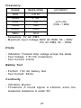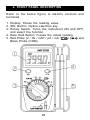
1
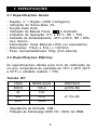
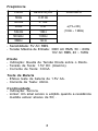
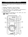
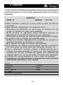
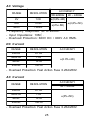
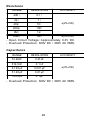
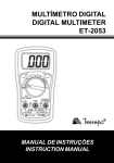
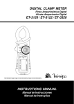
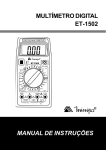
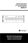
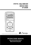
MULTÍMETRO DIGITAL DE BOLSO
POCKET SIZE DIGITAL MULTIMETER
ET-1700
MANUAL DE INSTRUÇÕES
INSTRUCTION MANUAL
ÍNDICE
1.
INTRODUÇÃO .................................................................. 02
2.
INFORMAÇÕES DE SEGURANÇA .................................. 02
3.
ESPECIFICAÇÕES ............................................................ 05
3.1 Especificações Gerais ................................................... 05
3.2 Especificações Elétricas ............................................... 05
4.
DESCRIÇÃO DO PAINEL FRONTAL ............................... 09
5.
OPERAÇÃO ...................................................................... 10
5.1 Medidas de Tensão AC / DC ......................................... 11
5.2 Medidas de Corrente AC / DC ....................................... 11
5.3 Medidas de Resistência ................................................ 12
5.4 Medidas de Capacitância .............................................. 12
5.5 Medidas de Freqüência ................................................. 13
5.6 Teste de Diodo .............................................................. 13
5.7 Teste de Continuidade ................................................... 14
5.8 Teste de Bateria ............................................................. 14
6.
MANUTENÇÃO ................................................................ 15
6.1 Troca de Bateria ............................................................ 15
6.2 Troca de Fusível ............................................................ 16
7.
ACESSÓRIOS ................................................................... 16
8.
GARANTIA ........................................................................ 17
1
1. INTRODUÇÃO
É um instrumento de teste portátil, compacto e operado
por bateria. Possui as seguintes características de
medida para aplicações principalmente domésticas e
de hobistas.
- Tensão DC e AC
- Corrente DC e AC
- Resistência
- Teste de Diodo e Continuidade
- Teste de Bateria de 1.5V AA
- Data Hold
- Freqüência
- Capacitância
2. INFORMAÇÕES DE SEGURANÇA
Este manual contém informações e advertências que
devem ser seguidas para uma operação segura do
instrumento e para mantê-lo em condições seguras de
operação.
No caso de qualquer dúvida com relação ao
comprometimento da proteção proporcionada pelo
instrumento, inutilize o multímetro imediatamente.
A proteção pode estar comprometida se, por exemplo,
o instrumento:
- Apresentar danos visíveis.
- Apresentar falha na execução de medidas.
- For armazenado por muito tempo em condições
desfavoráveis.
- For submetido a vibrações de transporte severas.
2
Termos deste Manual
CAUTELA
Identifica condições ou práticas que podem resultar em
danos ao instrumento ou nos equipamentos em teste.
ADVERTÊNCIA
Identifica condições ou práticas que podem resultar em
ferimentos pessoais ou até mesmo a perda da vida.
Termos Encontrados no Instrumento
ATENÇÃO: Refira-se ao manual.
PERIGO: Indica terminais onde podem existir
tensões perigosas.
ADVERTÊNCIA
1. Para evitar choque elétrico ou danos ao instrumento,
não aplique tensões superiores a 600V DC ou AC
RMS entre os terminais de entrada do instrumento.
2. Observe as precauções de segurança adequadas
quando trabalhar com tensões acima de 60V DC ou
30V AC RMS. Tais tensões podem expor o usuário a
choques elétricos perigosos.
3. Assegure-se de que as pontas de prova estejam em
boas condições de segurança.
3
CAUTELA
Para evitar danos ao instrumento:
- Desconecte as pontas de prova do circuito em teste
antes de mudar de função de medida.
- Nunca conecte tensões superiores a 600V DC ou
600V AC RMS.
- Nunca conecte tensão aos terminais de entrada quando
a chave rotativa estiver selecionada para medir
resistência.
Uso do Fusível Apropriado
Para evitar chamas perigosas, utilize o fusível correto,
do mesmo tipo e especificação de corrente e tensão de
operação, como especificado.
O uso do fusível com especificação diferente ou curtocircuitar o soquete do fusível é proibido e pode ter
conseqüências extremamente graves.
4
3. ESPECIFICAÇÕES
3.1 Especificações Gerais
-
Display: 3 ¾ Dígitos (4000 Contagens).
Indicação de Sobre-faixa: OL.
Função Data Hold.
Indicação de Bateria Fraca:
é mostrado.
Ambiente de Operação: 0°C a 40°C, RH < 75%.
Ambiente de Armazenamento: -20°C a 60°C, RH < 80%.
Uso Interno.
Alimentação: Duas Baterias LR44 (ou equivalente).
Dimensões: 116(A) x 81(L) x 13(P)mm.
Peso: Aproximadamente 100g (com bateria).
3.2 Especificações Elétricas
As especificações válidas para ciclo de calibração de
um ano, temperatura de operação de 18°C a 28°C (64°F
a 82°F) e umidade relativa < 70%.
Tensão DC
FAIXA
RESOLUÇÃO
PRECISÃO
400mV
100µV
±(0.8%+3D)
4V
1mV
40V
10mV
400V
100mV
±(1.5%+4D)
- Impedância de Entrada: 10MΩ.
- Proteção de Sobrecarga: 600V DC / 600V AC RMS.
5
Tensão AC
FAIXA
RESOLUÇÃO
4V
1mV
40V
10mV
400V
100mV
PRECISÃO
50Hz/60Hz
40 ~ 400Hz
±(0,8%+4D)
±(2%+5D)
±(2,8%+5D)
- Resposta em Freqüência: 40 a 400Hz.
- Impedância de Entrada: 10MΩ.
- Proteção de Entrada: 600V DC / 600V AC RMS.
Corrente DC
FAIXA
RE SOLUÇÃO
400µA
0.1µA
4000µA
1µA
40mA
10µA
200mA
100µA
PRECISÃO
±(2.0%+4D)
- Proteção de Sobrecarga: Fusível Ação Rápida 0.25A/
250V.
Corrente AC
FAIXA
RESOLUÇÃO
400µA
0.1µA
4000µA
1µA
40mA
10µA
200mA
100µA
PRECISÃO
40 ~ 400Hz
±(3%+5D)
- Proteção de Sobrecarga: Fusível Ação Rápida 0.25A/
250V.
6
Resistência
FAIXA
RESOLUÇÃO
400Ω
0.1 Ω
4kΩ
1Ω
40kΩ
10Ω
400kΩ
100Ω
4MΩ
1kΩ
20MΩ
10kΩ
PRECISÃO
±(2%+5D)
±(3%+5D)
- Tensão de Circuito Aberto: Aproximadamente 0.3V DC.
- Proteção de Sobrecarga: 300V DC / 300V AC RMS.
Capacitância
FAIXA
RESOLUÇÃO
51.20nF
0.01nF
512.0nF
0.1nF
5.120µF
0.001µF
51.20µF
0.01µF
100.0µF
0.1µF
PRECISÃO
±(3%+5D)
- Proteção de Sobrecarga: 300V DC / 300V AC RMS.
7
Freqüência
FAIXA
RESOLUÇÃO
50Hz
0.01Hz
500Hz
0. 1Hz
5kHz
1Hz
50kHz
10Hz
500kHz
100Hz
5MHz
1kHz
PRECISÃO
±(1%+3D)
(10Hz ~ 1MHz)
- Sensibilidade: 5V AC RMS.
- Tensão Máxima de Entrada: 300V AC RMS, 50 ~ 60Hz
10V AC RMS, 40 ~ 1MHz
Diodo
- Indicação: Queda de Tensão Direta sobre o Diodo.
- Tensão de Teste: 1.5V DC (máximo).
- Corrente de Teste: 0.6mA.
Teste de Bateria
- Efetua teste de bateria de 1.5V AA.
- Corrente de Teste: 40mA.
Continuidade
- Indicação: Sonora.
- Limiar: Um sinal sonoro é emitido quando a resistência
medida estiver abaixo de 50Ω.
8
4. DESCRIÇÃO DO PAINEL FRONTAL
Refira-se a figura abaixo para a localização dos controles
e terminais.
1. Display: Apresenta o valor da leitura.
2. Tecla SEL: Tecla de seleção de opção.
3. Chave Rotativa: Liga e desliga o instrumento e
seleciona a função e a faixa de medida.
4. Tecla Data Hold.
5. Pontas de Prova Vermelha (V / Hz / CAP / µA / mA /
/
) e Preta (COM).
9
5. OPERAÇÃO
ADVERTÊNCIA
Leia e entenda completamente este manual de instruções
antes de usar o instrumento.
O erro de operação ou de desacordo com as instruções
e advertências do manual de instruções pode resultar
em ferimentos sérios ou até fatais, além de danos
materiais.
Preparação e Cautela Antes das Medidas
1. Aguarde pelo menos 30 segundos após ter ligado o
instrumento antes de efetuar a medida.
2. A chave rotativa deve ser posicionada na função de
medida adequada antes de se conectar as pontas de
prova ao dispositivo a ser testado. Assegure- se de
desconectar as pontas de prova dos pontos de teste
antes de mudar a chave rotativa para uma nova
função ou faixa.
3. Se o multímetro é utilizado próximo de equipamentos
que gerem interferência eletromagnética, o display
pode tornar-se instável ou apresentar valores
incorretos.
4. Não permita que o instrumento entre em contato
com água ou qualquer outro líquido.
10
5.1 Medidas de Tensão AC / DC
ADVERTÊNCIA
Não aplique mais que 600V DC ou 600V AC RMS entre
as pontas de prova. Exceder este limite pode provocar
choques elétricos perigosos e danos ao instrumento.
Tome extremo cuidado para evitar o contato com o
circuito em teste quando estiver trabalhando com alta
tensão.
1. Posicione a chave rotativa na faixa de tensão e
pressione a tecla SEL para alternar entre tensão DC
(DCV) ou AC (ACV).
2. Conecte as pontas de prova sobre a fonte ou carga
a ser testada. A polaridade para tensão DC é
apresentada automaticamente.
3. Efetue a leitura do display.
5.2 Medidas de Corrente AC / DC
1. Posicione a chave rotativa na faixa de corrente
adequada. Para medida de corrente máxima de
4000µA, coloque a chave rotativa em µA. Para
corrente até 200mA, coloque a chave rotativa em
mA.
2. Pressione a tecla SEL para alternar entre corrente
DC (DCA) ou AC (ACA).
3. Desligue toda a alimentação do circuito e descarregue
todos os capacitores antes de abrir o circuito para
conectar o multímetro em série com a carga em
teste.
11
4. Conecte as pontas de prova e ligue a alimentação do
circuito. Efetue a leitura do display, a polaridade para
corrente DC é apresentada automaticamente.
5.3 Medidas de Resistência
1. Posicione a chave rotativa na faixa
.
ADVERTÊNCIA
Para evitar possíveis ferimentos pessoais ou danos ao
instrumento, assegure-se de que o dispositivo em teste
esteja totalmente desenergizado.
2. Pressione a tecla SEL até selecionar a função .
3. Conecte as pontas de prova sobre a resistência a
ser medida. E efetue a leitura do display.
NOTA: Se a resistência a ser medida exceder o valor
máximo da faixa, o display mostrará (OL). Para valores
de resistência de aproximadamente 1MΩ ou maiores, o
instrumento pode levar alguns segundos para estabilizar
a leitura. Isto é normal para leituras de resistências
altas.
5.4 Medidas de Capacitância
ADVERTÊNCIA
Para evitar possíveis ferimentos pessoais ou danos ao
instrumento, assegure-se de que o capacitor em teste
esteja totalmente descarregado.
1. Selecione a chave rotativa para a faixa de capacitância
(CAP).
12
2. Conecte o capacitor através das pontas de prova, aos
terminais de entrada apropriados.
3. Observe a polaridade quando necessário.
4. Efetue a leitura da capacitância diretamente do display.
NOTA: Antes da conexão do capacitor o display pode
apresentar leitura diferente de zero, entretanto, este
valor deve ser desprezado, pois a leitura correta será
sobreposta quando o capacitor for conectado.
5.5 Medidas de Freqüência
1. Selecione a chave rotativa para a faixa de freqüência
(Hz).
2. Conecte as pontas de prova, aos terminais de teste
apropriados.
3. Efetue a leitura de freqüência diretamente do display.
ADVERTÊNCIA
Para evitar possíveis ferimentos pessoais ou danos ao
instrumento, respeite os valores máximos de medida.
5.6 Teste de Diodo
. Pressione a
1. Posicione a chave rotativa na faixa
tecla SEL até selecionar a função .
2. Conecte as pontas de prova nos terminais do diodo em
teste. Normalmente a queda de tensão direta de um
diodo de silício bom está entre 0.4V e 0.9V. Se o diodo
em teste estiver defeituoso, 000 (curto-circuito) ou
próximo da sobre-faixa OL (aberto) será mostrado.
13
3. Inverta a conexão das pontas de prova. Se o diodo em
teste estiver bom, OL deve ser mostrado. Se o diodo
estiver em curto (ou resistivo), 000 ou um valor próximo
será mostrado.
5.7 Teste de Continuidade
1. Desligue toda a alimentação do circuito em teste.
Descarregue todos os capacitores do circuito.
Qualquer tensão presente durante o teste de
continuidade resultará em erros de leitura e pode
danificar o instrumento se a tensão exceder o limite
da proteção de sobrecarga. Posicione a chave rotativa
na faixa
. Pressione a tecla SEL até selecionar
a função .
2. Conecte as pontas de prova no circuito ou dispositivo
em teste. Assegure-se de que toda a alimentação do
circuito esteja desligada.
3. O circuito aberto será indicado com a condição de
sobre-faixa (OL).
4. A buzina irá tocar se a resistência do circuito for
menor que aproximadamente 50Ω. Após finalizar
todos os testes, desconecte as pontas de prova do
circuito.
5.8 Teste de Bateria
.
1. Gire a chave rotativa para a posição
2. Conecte as pontas de prova na bateria a ser testada.
3. Faça a leitura de tensão no display.
14
6. MANUTENÇÃO
ADVERTÊNCIA
Para evitar choque elétrico, remova as pontas de prova
do circuito antes de abrir o instrumento.
1. Reparos e serviços não cobertos por este manual de
instruções devem ser executados apenas por pessoas
qualificadas.
2. Periodicamente limpe a parte externa do instrumento
com pano macio umedecido em água ou detergente
neutro. Não utilize produtos abrasivos ou solventes.
6.1 Troca de Bateria
O multímetro é alimentado por bateria. Utilize o seguinte
procedimento para trocar a bateria.
1. Desconecte as pontas de prova do circuito em teste
e desligue o instrumento.
2. Coloque o multímetro com o painel frontal para baixo
em uma superfície que não danifique o painel.
3. Remova os parafusos localizados no painel traseiro.
4. Cuidadosamente levante o painel frontal, separandoo do gabinete traseiro.
5. Cuidadosamente retire as baterias, substituindo pelas
novas.
6. Encaixe o gabinete traseiro no frontal.
7. Recoloque os parafusos.
15
6.2 Troca de Fusível
Refira-se ao seguinte procedimento para examinar ou
trocar o fusível do multímetro.
1. Siga os passos 1 até 4 do item Troca de Bateria.
2. Remova o fusível defeituoso.
3. Instale o fusível novo de mesmo tamanho e
especificação.
4. Encaixe o gabinete traseiro no frontal.
5. Recoloque os parafusos.
7. ACESSÓRIOS
Após receber o seu instrumento, verifique a existência
dos seguintes itens:
1.
2.
3.
4.
Multímetro Digital no Estojo
Par de Pontas de Prova (Incorporado)
Manual de Instruções
Bateria (Instalada)
16
8. GARANTIA
O instrumento foi cuidadosamente ajustado e inspecionado. Se apresentar
problemas durante o uso normal, será reparado de acordo com os termos
da garantia.
GARANTIA
SÉRIE Nº
MODELO
ET-1700
1- Este certificado é válido por 6 (seis) meses a partir da data da
aquisição.
2- Será reparado gratuitamente nos seguintes casos:
A) Defeitos de fabricação ou danos que se verificar, por uso
correto do aparelho no prazo acima estipulado.
B) Os serviços de reparação serão efetuados somente no
departamento de assistência técnica por nós autorizado.
C) Aquisição for feita em um posto de venda credenciado da Minipa.
3- A garantia perde a validade nos seguintes casos:
A) Mau uso, alterado, negligenciado ou danificado por acidente ou
condições anormais de operação ou manuseio.
B) O aparelho foi violado por técnico não autorizado.
4- Esta garantia não abrange fusíveis, pilhas, baterias e acessórios
tais como pontas de prova, bolsa para transporte, termopar, etc.
5- Caso o instrumento contenha software, a Minipa garante que o
software funcionará realmente de acordo com suas especificações
funcionais por 90 dias. A Minipa não garante que o software não
contenha algum erro, ou de que venha a funcionar sem interrupção.
6- A Minipa não assume despesas de frete e riscos de transporte.
7- A garantia só será válida mediante o cadastramento deste certificado
devidamente preenchido e sem rasuras.
Nome:
Endereço:
Estado:
Nota Fiscal N°:
N° Série:
Nome do Revendedor:
Cidade:
Fone:
Data:
17
Cadastramento do Certificado de Garantia
O cadastramento pode ser feito através de um dos
meios a seguir:
- Correio: Envie uma cópia do certificado de garantia devidamente preenchido pelo correio para o endereço.
Minipa Indústria e Comércio Ltda.
At: Serviço de Atendimento ao Cliente
Alameda dos Tupinás, 33 - Planalto Paulista
CEP: 04069-000 - São Paulo - SP
- Fax: Envie uma cópia do certificado de garantia
devidamente preenchido através do fax 0xx11577-4766.
- e-mail: Envie os dados de cadastramento do certificado de garantia através do endereço
[email protected].
- Site: Cadastre o certificado de garantia através do
endereço http://www.minipa.com.br/sac.
IMPORTANTE
Os termos da garantia só serão válidos para produtos cujos certificados forem devidamente cadastrados. Caso contrário será exigido uma cópia da nota
fiscal de compra do produto.
Manual sujeito a alterações sem aviso prévio.
Revisão: 00
Data Emissão: 12/03/2004
18
19
TABLE OF CONTENTS
1.
INTRODUCTION .............................................................. 21
2.
SAFETY INFORMATION ................................................... 21
3.
SPECIFICATION ................................................................ 24
3.1 General Specification .................................................... 24
3.2 Electrical Specification .................................................. 24
4.
FRONT PANEL DESCRIPTION ........................................ 28
5.
OPERATION ...................................................................... 29
5.1 AC / DC Voltage Measurement ..................................... 30
5.2 AC / DC Current Measurement ..................................... 30
5.3 Resistance Measurement .............................................. 31
5.4 Capacitance Measurement ............................................ 31
5.5 Frequency Measurement ............................................... 32
5.6 Diode Test ..................................................................... 32
5.7 Continuity Test ............................................................... 33
5.8 Battery Test ................................................................... 33
6.
MAINTENANCE ................................................................ 34
6.1 Battery Replacement ...................................................... 34
6.2 Fuse Replacement ........................................................ 35
7.
ACCESSORIES ................................................................. 35
8.
WARRANTY ..................................................................... 36
20
1. INTRODUCTION
It is a portable test instrument, compact and operated
by battery. It has the following measurement features
for domestic and hobby applications.
- DC and AC Voltage
- DC and AC Current
- Resistance
- Diode and Continuity Test
- 1.5V AA Battery Test
- Data Hold
- Capacitance
- Frequency
2. SAFETY INFORMATION
This manual contains information and warnings that must
be followed for operating the meter safely and
maintaining the meter in a safe operating condition.
In the case of any doubt regarding the integrity of the
instrument, make the multimeter unusable immediately.
The protection provided by the meter may be impaired
if, for example:
- It shows visible damages.
- It fails in the execution of measurements.
- It was stored for a long time in unfavorable conditions.
- It was be submitted the severe vibrations in transport.
21
Terms in this Manual
CAUTION
It identifies practices or conditions that could result in
damage to the instrument or the equipment in test.
WARNING
It identifies practices or conditions that could result in
personal injury or loss of life.
Terms in the Instrument
ATENTION: Refer to the manual.
DANGER: It indicates terminals where dangerous
voltages can be present.
WARNING
1. To avoid electric shock or damages to the instrument,
do not apply voltages above 600V DC or AC RMS
between input terminals of the instrument.
2. Observe the proper safety precautions when working
with voltages above 60V DC or 30V AC RMS. Such
voltages can expose the user to dangerous electric
shocks.
3. Make sure that the test leads are in good conditions
of security.
22
CAUTION
To avoid damages to the instrument:
- Remove the test leads from test circuit before changing
the measurement function.
- Never connect voltages above 600V DC or 600V AC
RMS.
- Never connect voltage to the input terminals when the
rotary switch is selected to measure resistance.
Use of the Proper Fuse
To avoid dangerous fires, use the correct fuse, of the
same type and specification of operation current and
voltage, as specified. The use of the fuse with different
specification or short-circuit the fuse socket is prohibit
and can cause extremely serious injury.
23
3. SPECIFICATION
3.1 General Specification
-
Display: 3 ¾ Digits (4000 Counts).
Overrange Indication: OL.
Data Hold Function.
Low Battery Indication: Display shows
.
Operation Environment: 0°C to 40°C, RH < 75%.
Storage Environment: -20°C to 60°C, RH < 80%.
Internal Use.
Power: Two LR44 battery (or equivalent).
Dimensions: 116(H) x 81(W) x 13(D)mm.
Weight: Approx. 100g (including battery).
3.2 Electrical Specification
Accuracy specified to one year calibration period,
operation temperature of 18°C to 28°C (64°F to 82°F)
and relative humidity < 70%.
DC Voltage
RANGE
RESOLUTION
ACCURACY
400mV
100µV
±(0.8%+3D)
4V
1mV
40V
10mV
400V
100mV
±(1.5%+4D)
- Input Impedance: 10MΩ.
- Overload Protection: 600V DC / 600V AC RMS.
24
AC Voltage
RANGE
RESOLUTION
4V
1mV
40V
10mV
400V
100mV
ACCURACY
50Hz/60Hz
40 ~ 400Hz
±(0,8%+4D)
±(2%+5D)
±(2,8%+5D)
- Frequency Response: 40 to 400Hz.
- Input Impedance: 10MΩ.
- Overload Protection: 600V DC / 600V AC RMS.
DC Current
RA NGE
RE SOLUTION
400µA
0.1µA
4000µA
1µA
40mA
10µA
200mA
100µA
ACCURACY
±(2.0%+4D)
- Overload Protection: Fast Action Fuse 0.25A/250V.
AC Current
RANGE
RESOLUTION
400µA
0.1µA
4000µA
1µA
40mA
10µA
200mA
100µA
ACCURACY
40 ~ 400Hz
±(3%+5D)
- Overload Protection: Fast Action Fuse 0.25A/250V.
25
Resistance
RANGE
RESOLUTION
400Ω
0.1 Ω
4kΩ
1Ω
40kΩ
10Ω
400kΩ
100Ω
4MΩ
1kΩ
20MΩ
10kΩ
ACCURACY
±(2%+5D)
±(3%+5D)
- Open Circuit Voltage: Approximately 0.3V DC.
- Overload Protection: 300V DC / 300V AC RMS.
Capacitance
RANGE
RESOLUTION
51.20nF
0.01nF
512.0nF
0.1nF
5.120µF
0.001µF
51.20µF
0.01µF
100.0µF
0.1µF
ACCURACY
±(3%+5D)
- Overload Protection: 300V DC / 300V AC RMS.
26
Frequency
RANGE
RESOLUTION
50Hz
0.01Hz
500Hz
0. 1Hz
5kHz
1Hz
50kHz
10Hz
500kHz
100Hz
5MHz
1kHz
ACCURACY
±(1%+3D)
(10Hz ~ 1MHz)
- Sensitivity: 5V AC RMS.
- Maximum Input Voltage: 300V AC RMS, 50 ~ 60Hz
10V AC RMS, 40 ~ 1MHz
Diode
- Indication: Forward drop voltage across the diode.
- Test Voltage: 1.5V DC (maximum).
- Test Current: 0.6mA.
Battery Test
- Perform 1.5V AA battery test.
- Test Current: 40mA.
Continuity
- Indication: Buzzer.
- Threshold: A sound signal is emitted, when the
measured resistance is under 50Ω.
27
4. FRONT PANEL DESCRIPTION
Refer to the below figure to identify controls and
terminals.
1. Display: Shows the reading value.
2. SEL Button: Option selection key.
3. Rotary Switch: Turns the instrument ON and OFF,
and select the function.
4. Data Hold Button: Freeze the actual reading.
5. Red Probe (V / Hz / CAP / µA / mA /
/
) and
Black Probe (COM).
28
5. OPERATION
WARNING
Read and understand completely this instruction manual
before using the instrument.
Error in operation or in discordance with the warnings
and instructions of this manual, can result in material
damages and serious or deadly injuries.
Preparation and Caution Before Measurement
1. Wait at least 30 seconds after power on the instrument
before making measurements.
2. The rotary switch must be positioned in the proper
measurement function before connecting the test
leads to the device to be tested. Make sure to
disconnect the test leads from test points before
changing the rotary switch for a new function or
range.
3. If the multimeter is used next to equipment that
generates electromagnetic interference, the display
can become unstable or present incorrect values.
4. Do not allow that the instrument enters in contact with
water or any another liquid.
29
5.1 AC / DC Voltage Measurement
WARNING
Do not apply more than 600V DC or AC RMS between
the probes. Exceed these limits can result in dangerous
electric shock and damage to the instrument.
Take care to avoid contact with the circuit under test,
when working with high voltage.
1. Set the rotary switch to voltage function and press
the SEL button to select AC (ACV) or DC (DCV)
voltage.
2. Connect the test leads to the circuit under test. The
polarity to DC voltage is automatically displayed.
3. Read the measurement in the display.
5.2 AC / DC Current Measurement
1. Set the rotary switch to desired current range position.
For measures until 4000µA, turn the rotary switch to
µA position. For measures until 200mA, turn the rotary
switch to mA position.
2. Press the SEL button to select AC (ACA) or DC
(DCA) current.
3. Turn off all power from the circuit under test, and
discharge all capacitors before opening the circuit to
connect the multimeter in series with the circuit.
4. Connect the test leads and turn on the power. Make
the display reading. The polarity to DC current is
automatically displayed.
30
5.3 Resistance Measurement
1. Set the rotary switch to
position.
WARNING
To avoid possible damage to the meter or to the equipment under test, disconnect the circuit power and discharge all high-voltage capacitors before measuring
resistance.
is selected.
2. Press the SEL button until
3. Connect the test leads to the circuit under test and
make the resistance reading in the display.
NOTE: If the measured resistance exceed the maximum
value for the selected range, the display will show (OL).
To measure resistance around 1MΩ or higher, the
instrument can take some seconds to stabilize the
reading. It is normal to high resistance readings.
5.4 Capacitance Measurement
WARNING
To avoid possible damage to the meter or to the equipment under test, discharge all high-voltage capacitors
before taking the measurement.
1. Set the rotary switch to CAP position.
2. Connect the test leads to capacitor.
3. Pay attention to the polarity of capacitor when
necessary.
31
4. The reading will be showed in the display.
NOTE: Before connecting the capacitor the display can
show readings different from zero, however, this reading
must be despised, because the correct reading will be
displayed when the capacitor is connected.
5.5 Frequency Measurement
1. Set the rotary switch to frequency (Hz) function.
2. Connect the test leads to the appropriate test points.
3. Read the measurement in the display.
WARNING
To avoid possible damage to the meter or to the equipment under test, observe the maximum input voltage.
5.6 Diode Test
1. Set the rotary switch to
position. Press the SEL
button until
is selected.
3. Connect the test leads to the diode. Normally, the forward
voltage of a silicon diode is between 0.4V and 0.9V. If the
diode is damaged, the display will show 000 (short-circuit
condition) or OL (open condition).
4. Invert the connection of test leads. If the diode is good,
OL must be displayed. If it is damaged, (short-circuit or
resistive), 000 or a near value will be displayed.
32
5.7 Continuity Test
1. Turn off all power of the circuit under test. Discharge
all capacitors of circuit. Any voltage present during
the continuity test will result in reading error and can
damage the instrument if the voltage exceed overload
protection limit. Set the rotary switch to the
range position. Press the SEL button until
is
selected.
2. Connect the test leads to the circuit or device under
test. Make sure that the power of circuit or device is
turned off.
3. The open circuit will be indicated as overrange condition
(OL).
4. The buzzer will sound if the resistance of the circuit is
less than approximately 50Ω. After complete all tests,
disconnect the test leads from circuit.
5.8 Battery Test
1. Set the rotary switch to
position.
2. Connect the test leads to the battery that will be
tested.
3. Read the voltage in the display.
33
6. MAINTENANCE
WARNING
To avoid electric shock, remove the test leads from the
circuit before opening the multimeter.
1. Repairs and services not covered by this instruction
manual must be done only by qualified technician.
2. Periodically wipe the housing with a damp soft cloth
and mild detergent. Do not use abrasives or solvents.
6.1 Battery Replacement
This instrument is supplied with 1.5V (LR-44 or equivalent).
To replace the batteries, follow the procedure listed below.
1. Disconnect the test leads from the circuit under test
and turn off the meter.
2. Place the meter with front panel over a soft surface.
3. Remove the screws located in the rear case.
4. Carefully separate the front panel from the rear case.
5. Carefully remove the old battery replacing for a new
one.
6. Replace front panel in the rear case.
7. Refasten the screws.
34
6.2 Fuse Replacement
Refer to the following procedure to analyze or replace
the fuse.
1. Execute the Step 1 to 4 of item Battery Replacement.
2. Remove the damaged fuse.
3. Install the new fuse, with the same size and
specification.
4. Replace the front panel in the rear case.
5. Refasten the screws.
7. ACCESSORIES
After receiving your instrument, please check if the
listed accessories are included in the giftbox:
1.
2.
3.
4.
Digital Multimeter in the Case
Test Leads (one pair, built-in)
Instruction Manual
Battery (installed)
35
8. WARRANTY
This instrument was carefully calibrated and inspected. If any failure
occurs under normal use, this product will be repaired according to
warranty conditions and limitations.
WARRANTY
SERIAL Nº
MODEL ET-1700
1- The warranty period is 6 (six) months and begins on the date of
purchase.
2- It will be repaired free of charge in the following cases:
A)Manufacturing defects or damages occurred under normal
use of instrument within the warranty period.
B)The services to correct the failure will be done only in authorized
service center or personal will be allowed to fix this product.
C)If product is purchased through a Minipa’s authorized dealer.
3- Warranty will be void in case:
A)It has been misused, altered, neglected or damaged by accident
or abnormal conditions of operation or handling.
B)The instrument shows violations by a non authorized repair center.
4- This warranty does not apply to fuses, dry cells, batteries and
accessories as test leads, carrying case, thermo couple, etc.
5- For instrument with software, Minipa assumes responsibility that
the software will operate in accordance with its functional specifications for 90 days. Minipa will not guarantee that the software
will be error free or operate without interruption.
6- Minipa assumes no risk for damage in transit or transportation costs.
7- Warranty will be valid only after the registration of this
certificate.
Name:
Address:
City:
State:
Phone:
Sales Voucher N°:
Date:
Serial N°:
Sales Agent Name:
36
Warranty Certificate Registration Procedures
The registration can be made by the following ways:
- Mail:
- Fax:
- e-mail:
- Site:
Send a copy of warranty certificate correctly filled to the
following address.
Minipa Indústria e Comércio Ltda.
Att: Serviço de Atendimento ao Cliente
Alameda dos Tupinás, 33 - Planalto Paulista
CEP: 04069-000 - São Paulo - SP
Send a copy of warranty certificate correctly filled by fax
number 0xx11-577-4766.
Scanning this form and attach to your e-mail. Please send
to [email protected].
Register the warranty certificate by http://www.minipa.com.br/
sac.
IMPORTANT
The warranty conditions and limitations will be valid only to the certificates
correctly registered. In case the purchaser did not register, a sales
receipt showing the date of purchase will be required.
Manual specifications subject to change without notice.
Revision: 00
Date of Issue: 12/03/2004
37
Minipa Eletronics (Shangai) Co. Ltd.
Add: 5th, 111 Meisheng Rd. Waigaoqiao Free Trade Zone,
Shangai 200137, P.R. China
Tel: 86 21 5866 6003 - Fax: 86 21 5866 2054
E-mail: [email protected]
Site: www.minipa.net
Minipa Indústria e Comércio Ltda.
Al. dos Tupinás, 33 - Planalto Paulista - São Paulo - CEP: 04069-000
CGC: 43.743.749/0001-31
Site: http://www.minipa.com.br