1
IM3029
07/2009
Rev. 0
IDEALARC CV 420 & CV 505
OPERATOR’S MANUAL
MANUAL DE INSTRUÇÕES
LINCOLN ELECTRIC BESTER S.A.
ul. Jana III Sobieskiego 19A, 58-260 Bielawa, Poland
www.lincolnelectric.eu
Declaration of conformity
Declaração de conformidade
LINCOLN ELECTRIC BESTER S.A.
Declares that the welding machine:
Declara que a maquina de soldar:
IDEALARC CV 420
conforms to the following directives:
está em conformidade com as seguintes directivas:
2006/95/CEE, 2004/108/CEE
and has been designed in compliance with the following
standards:
e foi concebida de acordo com as seguintes normas:
EN 60974-1, EN 60974-10
(2009)
Paweł Lipiński
Operations Director
LINCOLN ELECTRIC BESTER S.A., ul. Jana III Sobieskiego 19A, 58-260 Bielawa, Poland
12/05
II
Declaration of conformity
Declaração de conformidade
LINCOLN ELECTRIC BESTER S.A.
Declares that the welding machine:
Declara que a maquina de soldar:
IDEALARC CV 505
conforms to the following directives:
está em conformidade com as seguintes directivas:
2006/95/CEE, 2004/108/CEE
and has been designed in compliance with the following
standards:
e foi concebida de acordo com as seguintes normas:
EN 60974-1, EN 60974-10
(2009)
Paweł Lipiński
Operations Director
LINCOLN ELECTRIC BESTER S.A., ul. Jana III Sobieskiego 19A, 58-260 Bielawa, Poland
12/05
III
English
Português
07/06
Do not dispose of electrical equipment together with normal waste!
In observance of European Directive 2002/96/EC on Waste Electrical and Electronic Equipment (WEEE) and its
implementation in accordance with national law, electrical equipment that has reached the end of its life must be
collected separately and returned to an environmentally compatible recycling facility. As the owner of the equipment,
you should get information on approved collection systems from our local representative.
By applying this European Directive you will protect the environment and human health!
Não deitar fora o equipamento eléctrico juntamente com o lixo normal!
Em conformidade com a directiva Europeia 2002/96/EC relativa a Resíduos Eléctricos e Equipamento Eléctricos (REEE)
e de acordo com a legislação nacional, os equipamentos deverão ser recolhidos separadamente e reciclados
respeitando o meio ambiente. Como proprietário do equipamento, deverá informar-se dos sistemas e lugares
apropriados para a recolha dos mesmos.
Ao aplicar esta Directiva Europeia protegerá o meio ambiente e a saúde humana!
12/05
THANKS! For having choosen the QUALITY of the Lincoln Electric products.
•
Please Examine Package and Equipment for Damage. Claims for material damaged in shipment must be notified immediately to
the dealer.
•
For future reference record in the table below your equipment identification information. Model Name, Code & Serial Number
can be found on the machine rating plate.
OBRIGADO! Por ter escolhido os produtos de QUALIDADE da Lincoln Electric.
•
Por favor, examine a embalagem e o equipamento para que não tenham danos. A reclamação de danos do material no
transporte deverá ser notificada imediatamente ao revendedor.
•
Para futura referência, registe abaixo a informação de identificação do equipamento. Modelo, Código e Número de Série podem
ser encontrados na chapa de características do equipamento.
Model Name, Modelo:
………………...…………………………….…………………………………………………………………………………………..
Code & Serial number, Código e Número de Série:
………………….………………………………………………..
…………………………………………………….……………..
Date & Where Purchased, Data e Local de Compra:
…………………………………………………………………...
……………………….…………………………………………..
ENGLISH INDEX
Safety ................................................................................................................................................................................................................ A-1
Installation and Operator Instructions................................................................................................................................................................ A-2
Electromagnetic Compatibility (EMC) ................................................................................................................................................................ A-4
Technical Specifications .................................................................................................................................................................................... A-5
INDÍCE PORTUGUÊS
Segurança ......................................................................................................................................................................................................... B-1
Instalação e Instruções de Funcionamento ....................................................................................................................................................... B-2
Compatibilidade Electromagnética (EMC)......................................................................................................................................................... B-4
Especificações Técnicas ................................................................................................................................................................................... B-5
Spare Parts, Lista de peças Sobressalentes.........................................................................................................................................................1
Electrical Schematic, Esquema Eléctrico ..............................................................................................................................................................4
Accessories, Accessórios......................................................................................................................................................................................5
IV
Safety
11/04
WARNING
This equipment must be used by qualified personnel. Be sure that all installation, operation, maintenance and repair
procedures are performed only by qualified person. Read and understand this manual before operating this equipment.
Failure to follow the instructions in this manual could cause serious personal injury, loss of life, or damage to this
equipment. Read and understand the following explanations of the warning symbols. Lincoln Electric is not responsible
for damages caused by improper installation, improper care or abnormal operation.
WARNING: This symbol indicates that instructions must be followed to avoid serious personal injury,
loss of life, or damage to this equipment. Protect yourself and others from possible serious injury or
death.
READ AND UNDERSTAND INSTRUCTIONS: Read and understand this manual before operating
this equipment. Arc welding can be hazardous. Failure to follow the instructions in this manual could
cause serious personal injury, loss of life, or damage to this equipment.
ELECTRIC SHOCK CAN KILL: Welding equipment generates high voltages. Do not touch the
electrode, work clamp, or connected work pieces when this equipment is on. Insulate yourself from
the electrode, work clamp, and connected work pieces.
ELECTRICALLY POWERED EQUIPMENT: Turn off input power using the disconnect switch at the
fuse box before working on this equipment. Ground this equipment in accordance with local electrical
regulations.
ELECTRICALLY POWERED EQUIPMENT: Regularly inspect the input, electrode, and work clamp
cables. If any insulation damage exists replace the cable immediately. Do not place the electrode
holder directly on the welding table or any other surface in contact with the work clamp to avoid the
risk of accidental arc ignition.
ELECTRIC AND MAGNETIC FIELDS MAY BE DANGEROUS: Electric current flowing through any
conductor creates electric and magnetic fields (EMF). EMF fields may interfere with some
pacemakers, and welders having a pacemaker shall consult their physician before operating this
equipment.
CE COMPLIANCE: This equipment complies with the European Community Directives.
FUMES AND GASES CAN BE DANGEROUS: Welding may produce fumes and gases hazardous to
health. Avoid breathing these fumes and gases. To avoid these dangers the operator must use
enough ventilation or exhaust to keep fumes and gases away from the breathing zone.
ARC RAYS CAN BURN: Use a shield with the proper filter and cover plates to protect your eyes from
sparks and the rays of the arc when welding or observing. Use suitable clothing made from durable
flame-resistant material to protect you skin and that of your helpers. Protect other nearby personnel
with suitable, non-flammable screening and warn them not to watch the arc nor expose themselves to
the arc.
WELDING SPARKS CAN CAUSE FIRE OR EXPLOSION: Remove fire hazards from the welding
area and have a fire extinguisher readily available. Welding sparks and hot materials from the welding
process can easily go through small cracks and openings to adjacent areas. Do not weld on any
tanks, drums, containers, or material until the proper steps have been taken to insure that no
flammable or toxic vapors will be present. Never operate this equipment when flammable gases,
vapors or liquid combustibles are present.
WELDED MATERIALS CAN BURN: Welding generates a large amount of heat. Hot surfaces and
materials in work area can cause serious burns. Use gloves and pliers when touching or moving
materials in the work area.
SAFETY MARK: This equipment is suitable for supplying power for welding operations carried out in
an environment with increased hazard of electric shock.
A-1
CYLINDER MAY EXPLODE IF DAMAGED: Use only compressed gas cylinders containing the
correct shielding gas for the process used and properly operating regulators designed for the gas and
pressure used. Always keep cylinders in an upright position securely chained to a fixed support. Do
not move or transport gas cylinders with the protection cap removed. Do not allow the electrode,
electrode holder, work clamp or any other electrically live part to touch a gas cylinder. Gas cylinders
must be located away from areas where they may be subjected to physical damage or the welding
process including sparks and heat sources.
Installation and Operator Instructions
protected according to appropriate rules.
Read this entire section before installation or operation
of the machine.
Check the input voltage, phase, and frequency supplied
to this machine before turning it on. Verify the
connection of grounding wires from the machine to the
input source. The allowable input are 3x220V and
3x380 V and 3x440V 50-60Hz (3x440V: factory default).
For more information about input supply refer to the
technical specification section of this manual and to the
rating plate of the machine.
Location and Environment
This machine will operate in harsh environments.
However, it is important that simple preventative
measures are followed to assure long life and reliable
operation:
•
•
•
•
•
•
•
Do not place or operate this machine on a surface
with an incline greater than 15° from horizontal.
Do not use this machine for pipe thawing.
This machine must be located where there is free
circulation of clean air without restrictions for air
movement to and from the air vents. Do not cover
the machine with paper, cloth or rags when
switched on.
Dirt and dust that can be drawn into the machine
should be kept to a minimum.
This machine has a protection rating of IP23. Keep
it dry when possible and do not place it on wet
ground or in puddles.
Locate the machine away from radio controlled
machinery. Normal operation may adversely affect
the operation of nearby radio controlled machinery,
which may result in injury or equipment damage.
Read the section on electromagnetic compatibility in
this manual.
Do not operate in areas with an ambient
temperature greater than 40°C.
If it is necessary to change the input voltage:
•
The input cable must be disconnected from the
mains supply and the machine switched OFF.
•
Remove the big side cover from the machine.
•
Reconnect X6 according to the diagram below.
•
Make sure that the amount of mains power available
from the input supply (connection) is adequate for
normal operation of the machine. The necessary
delayed fuse (or circuit breaker with "D" characteristic)
and cable sizes are indicated in the technical
specification section of this manual.
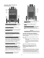
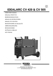
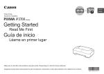
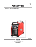
Refer to points [1] and [11] of the images below.
Duty cycle and Overheating
Output Connections
The duty cycle of a welding machine is the percentage of
time in a 10 minute cycle at which the welder can
operate the machine at rated welding current.
Refer to points [4], [5], [6] and [8] of the images below.
Controls and Operational Features
Example: 60% duty cycle:
Welding for 6 minutes.
Replace the big side cover.
Break for 4 minutes.
Excessive extension of the duty cycle will cause the
thermal protection circuit to activate.
Minutes
or decrease
duty cycle
Input Supply Connection
Installation and mains outlet socket shall be made and
A-2
1.
2.
WARNING
Read and understand the cooler manual before
connecting it to the machine.
Power Indicator Light: It indicates that the power is
on.
3.
Thermal Indicator Light: It indicates that the
machine is overloaded or that the cooling is not
sufficient.
4.
Low Inductance Negative Output Socket: The low
inductance connection is typically used for short arc
welding of mild steel, particularly on thin materials or
when using CO2 shielding gas.
5.
High Inductance Negative Output Socket: The high
inductance connection is more suitable for short arc
welding in heavier work or when using 75% Argon /
25% CO2 shielding gas. The connection produces a
softer arc and a flatter bead with more wash-in than
the low inductance connection. Spray type transfer
is possible with either connection.
6.
Wire Feeder Receptacle: 14-pins receptacle for
wire feeder. Provides connections for auxiliary
power of wire feeder.
7.
Wire Feeder Voltmeter Switch: This switch selects
the polarity of the wire feeder voltmeter, if so
equipped. When the welding torch is positive (MIG,
Outershield and some Innershield processes), set
the switch to "+". When the welding torch is
negative (most Innershield applications), set the
switch to "-".
8.
appropriate rules. Only qualified personnel shall
connect this plug.
Power Switch ON/OFF (O/I): It controls the
machine power input. Be sure the power source is
connected to the mains supply before turning power
on ("I").
Welding Cables Connections
Insert the plug of the work cable into the socket [4] or [5].
The other end of this cable connects to the work piece
with the work clamp.
Connect the wire feeder LINC FEED 33 to the power
source:
•
insert the positive welding cable into the output
socket [8].
•
insert the wire feeder control cable into the
socket [6] (see Accessories, Source/wire feeder
cable K10347-PG-xM or K10347-PGW-xM).
Use the shortest possible cable lengths.
Machine and Circuit Protection
The CV420 / CV505 is protected against overheating,
overload and accidental short-circuits.
If the machine is overheated, the thermal protection
circuit will decrease the output current to 0. The thermal
protection indicator [3] will turn on. The thermal
protection circuit will turn on the output current again,
when the machine is cooled.
The CV420 / CV505 is also electronically protected
against overload and accidental short-circuit. The
overload and short-circuit protection circuit automatically
reduces the output current to a safe value when it
detects an overload.
Positive Output Socket: Allows the connection, with
the power cable, to the wire feeder.
Maintenance
WARNING
For any maintenance or repair operations it is
recommended to contact the nearest Technical Service
Center or Lincoln Electric. Maintenance or repairs
performed by unauthorized service centers or personnel
will null and void the manufacturer's warranty.
The frequency of the maintenance operations may vary
in accordance with the working environment where the
machine is placed.
Any noticeable damage should be reported immediately.
Routine maintenance (everyday)
•
•
9.
•
Covered Hole: For CO2 gas heater socket (see
accessories, K14009-1 CO2 Socket Kit).
•
10. Fuse: This fuse protects the wire feeder supply
circuit (see Spare Parts).
Check cables and connections integrity. Replace, if
necessary.
Remove the spatters from the welding gun nozzle.
Spatters could interfere with the shielding gas flow
to the arc.
Check the welding gun condition: replace it, if
necessary.
Check condition and operation of the cooling fan.
Keep clean its airflow slots.
Periodic maintenance (every 200 working hours
but at list once every year)
11. Power Input Cable: Connect the proper plug to the
input cable then into the rated output according to
Perform the routine maintenance and, in addition:
•
Keep the machine clean. Using a dry (and low
A-3
•
pressure) airflow, remove the dust from the external
case and from the cabinet inside.
Check and tighten all screws.
WARNING
Mains supply network must be disconnected from the
machine before each maintenance and service. After
each repair, perform proper tests to ensure safety.
Electromagnetic Compatibility (EMC)
11/04
This machine has been designed in accordance with all relevant directives and standards. However, it may still generate
electromagnetic disturbances that can affect other systems like telecommunications (telephone, radio, and television) or
other safety systems. These disturbances can cause safety problems in the affected systems. Read and understand
this section to eliminate or reduce the amount of electromagnetic disturbance generated by this machine.
This machine has been designed to operate in an industrial area. To operate in a domestic area it is
necessary to observe particular precautions to eliminate possible electromagnetic disturbances. The
operator must install and operate this equipment as described in this manual. If any electromagnetic
disturbances are detected the operator must put in place corrective actions to eliminate these disturbances
with, if necessary, assistance from Lincoln Electric.
Before installing the machine, the operator must check the work area for any devices that may malfunction because of
electromagnetic disturbances. Consider the following.
•
Input and output cables, control cables, and telephone cables that are in or adjacent to the work area and the
machine.
•
Radio and/or television transmitters and receivers. Computers or computer controlled equipment.
•
Safety and control equipment for industrial processes. Equipment for calibration and measurement.
•
Personal medical devices like pacemakers and hearing aids.
•
Check the electromagnetic immunity for equipment operating in or near the work area. The operator must be sure
that all equipment in the area is compatible. This may require additional protection measures.
•
The dimensions of the work area to consider will depend on the construction of the area and other activities that are
taking place.
Consider the following guidelines to reduce electromagnetic emissions from the machine.
•
Connect the machine to the input supply according to this manual. If disturbances occur if may be necessary to take
additional precautions such as filtering the input supply.
•
The output cables should be kept as short as possible and should be positioned together. If possible connect the
work piece to ground in order to reduce the electromagnetic emissions. The operator must check that connecting
the work piece to ground does not cause problems or unsafe operating conditions for personnel and equipment.
•
Shielding of cables in the work area can reduce electromagnetic emissions. This may be necessary for special
applications.
WARNING
The Class A equipment is not intended for use in residential locations where the electrical power is provided by the public
low-voltage supply system. There may be potential difficulties in ensuring electromagnetic compatibility in those
locations, due to conducted as well as radiated disturbances.
WARNING
This equipment complies with IEC 61000-3-12 provided that the short-circuit power Ssc is greater than or equal to
7,76MVA for CV 420 and 9,95MVA for CV 505 at the interface point between the user’s supply and the public system. It
is the responsibility of the installer or user of the equipment to ensure, by consultation with the distribution network
operator if necessary, that the equipment is connected only to a supply with a short circuit power Ssc greater than or
equal to 7,76MVA (CV 420) and 9,95MVA (CV 505).
A-4
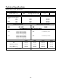
Technical Specifications
IDEALARC CV 420 & CV 505
Input Voltage
220/380 / 440V ± 10%
Three Phase
Duty Cycle
(Based on a 10 min. period)
420:
60%
100%
505:
INPUT
Input Power at Rated Output
420:
22kVA @ 60% Duty Cycle
505:
29kVA @ 60% Duty Cycle
RATED OUTPUT AT 40°C
Output Current
60%
100%
Frequency
50-60 Hz
Output Voltage
420A
325A
35.0 Vdc
30.3 Vdc
500A
385A
OUTPUT RANGE
39.0 Vdc
33.3 Vdc
Welding Current Range
420:
505:
EMC Group / Class
II / A
II / A
Maximum Open Circuit Voltage
420:
30A - 420A
43 Vdc
505:
40A - 500A
48 Vdc
RECOMMENDED INPUT CABLE AND FUSE SIZES
Fuse or Circuit Breaker Size
Input Power Cable
2
420:
63A (for 220V) Superlag
32A (for 380V) Superlag
32A (for 440V) Superlag
420:
4 Conductor, 6mm
505:
63A (for 220V) Superlag
32A (for 380V) Superlag
32A (for 440V) Superlag
505:
4 Conductor, 10mm
PHYSICAL DIMENSIONS
Height
Width
2
Length
Weight
420:
420 (water version):
870 mm
870 mm
565 mm
700 mm
1030 mm
1030 mm
139 kg
165 kg
505:
505 (water version):
Operating Temperature
-10°C to +40°C
870 mm
870 mm
565 mm
700 mm
1030 mm
1030 mm
Storage Temperature
-25°C to +55°C
147 kg
173 kg
A-5
Segurança
11/04
AVISO
Este equipamento deve ser utilizado por pessoal qualificado. Verifique que toda a instalação, operação, manutenção e
procedimentos de reparação são realizados apenas por pessoal qualificado. Leia e compreenda este manual antes de
começar a usar este equipamento. Falha para com as seguintes instruções deste manual pode causar sérios danos
pessoais, perda de vida ou danos no equipamento. Leia e compreenda as seguintes explicações de símbolos de aviso.
A Lincoln Electric não é responsável por danos causados por instalação imprópria, manutenção imprópria ou utilização
anormal.
AVISO: Este Símbolo indica que as instruções devem ser seguidas de forma a evitar danos
pessoais. Proteja-se a si próprio e os outros de possíveis danos sérios ou morte.
LER E COMPREENDER INSTRUÇÕES: Leia e compreenda este manual antes de utilizar este
equipamento. Arco soldadura pode ser perigosa. O não seguimento das instruções contidas neste
manual pode causar sérios danos pessoais, perda de vidas ou danos a este equipamento.
CHOQUES ELÉTRICOS PODEM MATAR: Equipamento de soldadura gera alta tensão. Não toque o
eléctrodo, grampo trabalho, ou peças ligadas trabalho quando este equipamento está ligado. Isolarse do eléctrodo, grampo de trabalho, e peças de trabalho conectadas.
EQUIPAMENTOS ELÉCTRICOS: Desligue a entrada de alimentação utilizando o interruptor na caixa
de fusível antes de trabalhar com este equipamento. Ligue este equipamento eléctrico á terra em
conformidade com a regulamentação local.
EQUIPAMENTOS ELÉCTRICOS: Inspeccionar regularmente o input, eléctrodo, cabos de fixação e
de trabalho. Se existe algum dano de isolamento substituir o cabo de imediato. Não coloque o
eléctrodo titular directamente sobre a mesa soldadura ou qualquer outra superfície em contacto com
o grampo de trabalho para evitar o risco de ignição arco acidental.
CAMPOS ELÉCTRICOS E MAGNÉTICOS PODEM SER PERIGOSOS: A corrente eléctrica flui
através de qualquer condutor cria campos eléctricos e magnéticos (EMF). Campos EMF podem
interferir com alguns pacemakers, e soldadores com um pacemaker devem consultar seu médico
antes de utilizar este equipamento.
CONFORMIDADE CE: Este equipamento está em conformidade com as directivas da Comunidade
Europeia.
FUMOS E GASES PODEM SER PERIGOSOS: Soldadura pode produzir fumos e gases nocivos
para a saúde. Evite respirar estes fumos e gases. Para evitar estes perigos, o operador deve utilizar
ventilação ou exaustão suficiente para manter fumos e gases de distância da zona de respiração.
RAIOS ARC PODEM QUEIMAR: Use um escudo com o bom filtro e cobrir chapas para proteger os
seus olhos de faísca e os raios do arco quando soldadura ou observando. Use roupas adequadas
chama-duráveis feitos de material resistente para protegê-lo de que a sua pele e ajudantes. Proteger
o pessoal próximo adequadamente, não inflamável rastreio e avisá-los a não assistir ao arco, nem se
exporem ao arco.
FAÍSCA DE SOLDADURA PODE CAUSAR INCÊNDIO OU EXPLOSÃO: Eliminar os riscos de
incêndio na área de soldadura e ter um extintor de incêndio, prontamente disponíveis. A faísca da
solda e materiais quentes a partir do processo de para assegurar que não inflamáveis ou vapores
tóxicos irão estar presente. Nunca operar este soldagem pode facilmente passar por pequenas
rachaduras e aberturas de áreas adjacentes. Não soldar em qualquer cisternas, tambores,
contentores, ou qualquer material até serem adoptadas medidas adequadas equipamento quando
gases inflamáveis, vapores ou líquidos combustíveis estão presentes.
MATERIAIS SOLDADOS PODEM QUEIMAR: Solda gera uma grande quantidade de calor.
Superfícies quentes e materiais na área de trabalho pode causar queimaduras graves. Use luvas e
alicates quando tocar ou mover materiais na zona de trabalho.
B-1
MARCA DE SEGURANÇA: Este equipamento é adequado para fornecer energia para operações de
soldadura realizadas em um ambiente com maior perigo de choque eléctrico.
GARRAFA PODE EXPLODIR SE DANIFICADA: Use apenas cilindros de gás comprimido que
contêm a correcta blindagem de gás para o processo de funcionamento devidamente utilizados e
reguladores concebidos para o gás e da pressão utilizada. Mantenha sempre as garrafas em uma
posição vertical segura encadeada para um apoio fixo. Não mova ou transporte garrafas de gás com
a protecção tampa removida. Não permitir o eléctrodo, eléctrodo titular, grampo trabalho ou de
qualquer outra parte electricamente vivo para tocar um cilindro de gás. As garrafas de gás devem
estar situadas fora das áreas onde eles possam ser submetidos aos danos físicos ou a soldagem
processo incluindo faísca e de fontes de calor.
Instalação e Instruções de Funcionamento
Leia toda esta secção antes da instalação ou utilização
da máquina.
Localização e Ambiente
Minutos
ou decrescente
duty cycle
Esta máquina vai trabalhar em ambientes agressivos.
No entanto, é importante que umas simples medidas
preventivas sejam seguidas para garantir uma vida
longa e um trabalho confiável.
Conexão da Alimentação de Entrada
•
Instalação e principal encaixe de saída devem ser feito e
protegido de acordo com as regras apropriadas.
•
•
•
•
•
•
Não coloque ou opere esta máquina em uma
superfície com uma inclinação superior a 15° da
horizontal.
Não utilizar esta máquina para derreter tubos.
Este aparelho deve estar localizado onde existe
livre circulação de ar limpo, sem restrições de
circulação de ar a partir do ar e ventiladores. Não
cubra a máquina com papel, tecido ou trapos
quando ligado.
A sujidade e o pó que pode entrar na máquina
devem ser reduzido ao mínimo.
Esta máquina tem um rating de protecção IP23.
Mantenha-a seca, quando possível, e não colocá-la
em solo húmido ou em poças.
Localize a máquina fora de controlos de rádio de
máquinas. O funcionamento normal pode afectar
negativamente o funcionamento dos controlos de
rádio da máquina vizinha, o que pode resultar em
prejuízo ou dano material. Leia a sessão sobre
compatibilidade electromagnética neste manual.
Não operar em áreas com uma temperatura
ambiente superior a 40° C.
Verifique a tensão de entrada, fase, e frequência de
alimentação desta máquina antes de a ligar. Verifique a
conexão dos fios terra da máquina á fonte de entrada.
As tensões de entrada permitidas são 3x220V e 3x380V
e 3x440V 50-60Hz (3x440V: padrão). Para mais
informação sobre a alimentação de entrada ver a
secção de especificações técnicas neste manual e a
placa de características da máquina.
Se for necessário mudar a fonte de alimentação de
tensão:
•
Assegure-se que o cabo de entrada deve ser
desligado da fonte de alimentação e a máquina
deve ser desligada.
•
Remova o grande painel lateral da máquina.
•
Reconecte X6 de acordo com o diagrama abaixo.
Duty Cycle e Sobreaquecimento
•
O duty cycle de uma máquina de soldadura é a
percentagem de tempo num ciclo de 10 minutos em que
o soldador pode operar a máquina à escala de corrente
de soldadura.
Coloque o grande painel lateral.
Assegure-se que a quantidade de potência disponível
da conexão de entrada é adequada para o
funcionamento normal da máquina. O fusível de atraso
necessário (ou disjuntor com característica “D”) e
tamanhos de cabos são indicados na secção de
especificação técnica deste manual.
Exemplo: 60% duty cycle:
Referência aos pontos [1] e [11] das imagens abaixo.
Soldar durante 6 minutos.
Conexões de Saída
Pausa durante 4 minutos.
Referência aos pontos [4], [5], [6] e [8] da imagem
abaixo.
Extensão excessiva do duty cycle vai causar a activação
do circuito de protecção térmica.
B-2
Controlos e Especificações de
Funcionamento
9.
1.
Interruptor de Potência ON/OFF (O/I): Controla a
potência de entrada da máquina. Certifique-se que
a fonte de alimentação está ligada á alimentação
principal antes de ligar a máquina ("I").
2.
Luz Indicadora de Potência: Esta indica que a
alimentação está ligada.
3.
Luz Térmica Indicadora: Esta indica que a máquina
está em sobreaquecimento ou que a refrigeração
não é suficiente.
4.
Alta Indução Negativa do Encaixe de Saída: A
conexão de alta indutância é mais apropriada para
um curto arco de soldadura em trabalho pesado ou
quando se usa um gás de protecção com 75%
Árgon / 25% CO2. A conexão produz um arco mais
macio e um colar adular com mais barrela que a
conexão de baixa indutância. A transferência tipo
spray é possível em ambas as conexões.
6.
Receptáculo do Fio Alimentador: Receptáculo de
14-pinos para o fio alimentador. Fornece conexões
para potência auxiliar do fio alimentador.
7.
8.
10. Fusível: Este fusível protege o circuito de
alimentação do fio (ver Lista de Peças).
11. Cabo de Alimentação de Entrada: Ligue a ficha
adequada ao cabo de entrada, dentro da escala de
saída de acordo com as regras apropriadas.
Apenas pessoas qualificadas devem conectar esta
ficha.
AVISO
Ler e perceber o manual do refrigerador antes de o
conectar á máquina.
Baixa Indução Negativa do Encaixe de Saída: A
conexão de baixa indutância é tipicamente usada
para um curto arco de soldadura de aço temperado,
particularmente em materiais finos ou quando se
usa protecção a gás CO2.
5.
Tampa de Cobertura: Para encaixe do radiador de
gás CO2 (ver acessórios, kit de encaixe CO2
K14009-1).
Conexão dos Cabos de Soldadura
Insira a ficha do cabo de trabalho no encaixe [4] ou [5].
A outra ponta deste cabo liga á peça de trabalho com o
grampo de trabalho.
Ligue o alimentador de fio LINC FEED 33 á fonte de
alimentação:
•
Insira o cabo positivo de soldadura no encaixe
de saída [8].
•
Insira o cabo de controlo do alimentador de fio
no encaixe [6] (ver Acessórios, Fonte/cabo
alimentador de fio K10347-PG-xM ou K10347PGW-xM).
Use o mínimo comprimento possível de cabo.
Máquina e Circuito de Protecção
Interruptor Voltímetro do Fio Alimentador: Este
interruptor selecciona a polaridade do voltímetro do
fio alimentador, se equipado. Quando a tocha de
soldadura é positiva (MIG, processos Outershield e
alguns Innershield), fixar o interruptor para o "+".
Quando a tocha de soldadura é negativa (a maioria
das aplicações Innershield), fixar o interruptor para
o "-".
O CV420 / CV505 é protegido contra o
sobreaquecimento, sobrecarga e curto-circuitos
acidentais.
Se a máquina está em sobreaquecimento, o circuito de
protecção térmica vai diminuir a corrente de saída para
0. O indicador de protecção térmica [3] vai acender-se.
O circuito de protecção térmica vai voltar a ligar a
corrente de saída, quando a máquina estiver arrefecida.
Encaixe Positivo de Saída: Permite a conexão,
com o cabo de potência, ao fio alimentador.
O CV420 / CV505 é também protegido electronicamente
B-3
contra sobrecargas e curto-circuitos acidentais. A
protecção de sobrecarga e curto-circuito
automaticamente reduz a corrente de saída para um
valor seguro quando uma sobrecarga é detectada.
•
Manutenção
substitua-a, se necessário.
Verifique a condição e operação da ventoinha de
refrigeração. Mantenha limpa as fendas de fluxo de
ar.
Manutenção Periódica (a cada 200 horas de
trabalho mas raramente não mais do que uma
vez por ano)
AVISO
Para qualquer tipo de manutenção ou reparação é
recomendado que contacte o centro de serviço técnico
mais próximo ou a Lincoln Electric. A manutenção e as
reparações realizadas por centros de serviço ou pessoal
não autorizado, anulará e terminará a garantia do
fabricante.
Realize a manutenção de rotina e, em adicionalmente:
•
Mantenha a máquina limpa. Usando um
compressor (e baixa pressão), remova a sujidade
da caixa externa e da cabine interior.
•
Verifique e aperte todos os parafusos.
AVISO
A fonte de alimentação deve ser desligada da máquina
antes de cada manutenção e serviços. Após cada
reparação, realizar testes para garantir a segurança
adequada.
A frequência da operação de manutenção pode variar
de acordo com o ambiente de trabalho onde a máquina
está localizada.
Qualquer dano notável deve ser reportado
imediatamente.
Manutenção de Rotina (todos os dias)
•
•
•
Verifique os cabos e as integridades das conexões.
Substitua, se necessário.
Remova os salpicos do nariz da pistola. Os
salpicos podem interferir com a protecção do fluxo
de gás para o arco.
Verifique a condição da pistola de soldadura:
Compatibilidade Electromagnética (EMC)
11/08
Esta máquina foi concebida de acordo com todas as directivas e normas. No entanto, ela ainda pode gerar
perturbações electromagnéticas que podem afectar outros sistemas como o de telecomunicações (telefone, rádio e
televisão) ou outros sistemas de segurança. Estas perturbações podem causar problemas de segurança no sistema
afectado. Ler e compreender esta secção para eliminar ou reduzir a quantidade de perturbação electromagnética
gerada por esta máquina.
Esta máquina foi concebida para funcionar em uma área industrial. Para operar em uma área doméstica,
é necessário observar precauções especiais para eliminar possíveis perturbações electromagnéticas. O
operador deve instalar e operar este equipamento como descrito neste manual. Se forem detectadas
quaisquer perturbações electromagnéticas o operador deve pôr em prática acções correctivas para
eliminar a estes distúrbios, se necessário, com a assistência de Lincoln Electric.
Antes de instalar a máquina, o operador deve verificar a área de trabalho para qualquer dispositivo que pode mau
funcionamento devido a perturbações electromagnéticas. Considere o seguinte.
•
Entrada e saída cabos, controle cabos, e que estão em cabos telefónicos ou adjacente à zona de trabalho e da
máquina.
•
Rádio e / ou transmissores e receptores de televisão. Computadores ou equipamento informático controlada.
•
Segurança e equipamentos de controlo de processos industriais. Equipamento para calibração e de medição.
•
Dispositivos médicos pessoais tais como estimuladores cardíacos e de auxiliares de audição.
•
Verifique a imunidade electromagnética dos equipamentos operando em ou perto da zona de trabalho. O operador
deve estar certo de que todos os equipamentos na área são compatíveis. Isto poderá exigir medidas
suplementares de protecção.
•
As dimensões da área de trabalho para que considerar dependerão da construção do espaço e de outras
actividades que estão a ter lugar.
Considere as seguintes orientações para reduzir as emissões electromagnéticas a partir da máquina.
•
Ligue a máquina para o fornecimento de entrada de acordo com este manual. Se ocorrerem perturbações pode ser
necessário tomar precauções adicionais, tais como filtragem da alimentação de entrada.
•
A saída cabos devem ser mantidos tão curtas quanto possível e devem ser posicionado em conjunto. Se possível
conectar a peça de trabalho ao solo, a fim de reduzir as emissões electromagnéticas. O operador deve verificar
que ligar a peça de trabalho ao solo não causa problemas ou torna inseguras as condições de funcionamento para
pessoal e equipamento.
•
Blindagem de cabos na zona de trabalho pode reduzir as emissões electromagnéticas. Isto pode ser necessário
para aplicações especiais.
B-4
AVISO
Os equipamentos de Classe A não são destinados para uso em localizações residenciais onde a potência eléctrica é
fornecida pelo sistema público de fonte de baixa tensão. Podem haver potenciais dificuldades em assegurar a
compatibilidade electromagnética naqueles locais, devido á condução tal como distúrbios radioactivos.
AVISO
Este equipamento está em conformidade com IEC 61000-3-12 desde que a potência de curto-circuito Ssc é maior ou
igual a 7,76MVA para 420 CV e 9,95MVA para 505 CV no ponto de interface entre a fonte do utilizador e o sistema
público. Isto é responsável pela instalação ou uso dos equipamentos para assegurar, por consulta com o operador da
rede de distribuição se necessário, que o equipamento está conectado apenas a uma fonte com uma potência de curtocircuito Ssc maior ou igual a 7,76MVA (420 CV) e 9,95MVA (505 CV).
Especificações Técnicas
IDEALARC CV 420 & CV 505
Tensão de Entrada
220 /380/ 440V ± 10%
Três Fases
Duty Cycle
ENTRADA
Potência de Entrada à Escala de Saída
420:
22 kVA @ 60% Duty Cycle
505:
29 kVA @ 60% Duty Cycle
ESCALA DE SAÍDA A 40°C
Corrente de Saída
Grupo EMC / Classe
II / A
II / A
Frequência
50-60 Hz
Tensão de Saída
(Baseado num período de 10 min.)
420:
60%
100%
420A
325A
35.0 Vdc
30.3 Vdc
505:
60%
100%
500A
385A
ESCALA DE SAÍDA
39.0 Vdc
33.3 Vdc
Escala da Corrente de Soldadura
420:
505:
Tensão Máxima em Circuito Aberto
420:
30A - 420A
43 Vdc
505:
40A - 500A
48 Vdc
CABOS DE ENTRADA E TAMANHOS DOS FUSÍVEIS RECOMENDADOS
Tamanho do Fusível ou Disjuntor
Cabo de Potência de Entrada
420:
63A (for 220V) Superlag
32A (for 380V) Superlag
32A (for 440V) Superlag
505:
505:
63A (for 220V) Superlag
32A (for 380V) Superlag
32A (for 440V) Superlag
DIMENSÕES FÍSICAS
Altura
Largura
420:
420 (versão a água):
420:
870 mm
870 mm
565 mm
700 mm
505:
870 mm
505 (versão a água):
870 mm
Temperatura de Funcionamento
-10°C a +40°C
2
4 Condutor, 6mm
2
4 Condutor, 10mm
Comprimento
Peso
1030 mm
1030 mm
139 kg
165 kg
565 mm
1030 mm
147 kg
700 mm
1030 mm
173 kg
Temperatura de Armazenamento
-25°C a +55°C
B-5
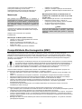
Spare Parts, Lista de peças Sobressalentes
12/05
Part List reading instructions
•
•
•
Do not use this part list for a machine if its code number is not listed. Contact the Lincoln Electric Service Department for any code
number not listed.
Use the illustration of assembly page and the table below to determine where the part is located for your particular code machine.
Use only the the parts marked "X" in the column under the heading number called for in the assembly page (# indicate a change in this
printing).
Leitura de instruções de lista de peças sobressalentes
•
•
•
Não utilizar esta lista para participar de uma máquina se o seu número de código não estiver na lista. Contacte o Departamento Lincoln
Electric Serviço para qualquer número de códigos não listados.
Use a ilustração de página e de montagem da tabela abaixo para determinar a parte onde está localizado o seu código de máquina.
Utilize apenas as peças marcando o "X" na coluna sob o número da posição na chamada para a montagem página (# indicam uma
mudança nesta impressão).
SP50166/50167 Rev. 0
07/03
CODE
NO.:
50166
50167
K NO.:
K14028-3A
K14029-3A
FIGURE NO.:
CV 420 AIR 220/380/440V 3Ph
CV 505 AIR 220/380/440V 3Ph
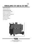
Machine
Assembly
(Rear side)
ASSEMBLY
PAGE NAME
Machine
Assembly
IDEALARC CV 420 & CV 505
A
B
1
2
1
2
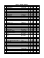
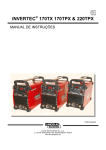
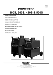
Figure A
1
Figure A: Machine Assembly
Item
1
2
3
4
5
6
7
8
9
10
11
12
13
14
15
16
17
18
19
20
21
22
23
24
25
26
27
28
29
30
31
32
33
34
35
36
37
38
39
40
41
42
43
44
45
46
47
48
49
50
51
52
53
54
55
56
57
58
59
60
61
62
Description
MAIN TRANSFORMER T1
MAIN TRANSFORMER T1
RECTIFIER SET V1
RECTIFIER SET V1
CHOKE L1
CHOKE L1
FAN M1
CAPACITORS C1,C2,C3
SHUNT R2
RESISTOR R1
CONDUCTOR-RAIL
CONDUCTOR-RAIL
DIVIDER PANEL
MAIN SWITCH S1
CONDUCTOR-RAIL
CONDUCTOR-RAIL
CONDUCTOR-RAIL
DIVIDER PANEL
DIVIDER PANEL
TURNING WHEEL
WHEEL
MAIN SWITCH S1
SOCKET X2, X3, X4
SOCKET X10
VOLTMETER POLARITY SWITCH S9
FRONT DECAL
FRONT PANEL
COVER
LABEL
LABEL
SIGNAL LAMP H1
SIGNAL LAMP H2
LEFT HOLDER
LEFT BRACKET (HANDLE)
RIGHT HOLDER
RIGHT BRACKET (HANDLE)
LEFT SIDE HANDLE ASSEMBLY
+ CAP
RIGHT SIDE HANDLE ASSEMBLY
+ CAP
EDGE SHIELD
HANDLE
CARRIAGE SUPPORT
CAPACITORS C5,C6,C7
CAPACITOR C4
CONTROL PCB
GROUND CABLE WITH WORK CLAMP -3m
POWER RESISSTOR R3
DIVIDER PANEL
SHELF
TERMINAL BLOCK
LABEL (U,V,W)
WALL RING
SUPPORT
BOTTOM
TOP PANEL
LABEL (WARNING)
TRAY
LEFT SIDE PANEL (not show)
LABEL (LEFT SIDE PANEL) (not show)
LABEL (LEFT SIDE PANEL) (not show)
RIGHT SIDE PANEL (not show)
RIGHT (LEFT SIDE PANEL) (not show)
RIGHT (RIGHT SIDE PANEL) (not show)
Part Number
R-4034-097-1R
R-4034-098-1R
R-0010-272-1AR
R-0010-273-1AR
R-4034-002-2R
R-4034-077-1R
R-8040-055-1R
1158-125-374R
0941-712-026R
1158-112-360R
R-1010-014-1R
R-1010-015-1R
R-3019-160-1/08R
1115-260-009R
R-1010-018-1R
R-1010-019-1R
R-1010-020-1R
R-3019-159-1/08R
R-3019-161-1/08R
1029-660-127R
1029-660-250R
1115-260-118R
C-2986-001-3R
1158-641-130R
1158-650-023R
2719-107-254R
R-3019-028-1/08R
R-8040-035-2R
2719-107-992R
2719-107-993R
0917-421-041R
0917-421-024R
1362-212-002R
D-3631-908-1/08R
1362-212-003R
D-3631-908-2/08R
1362-212-006R
1362-212-004R
1362-212-007R
1362-212-004R
1362-212-010R
0562-230-005R
1361-598-181R
1158-128-043R
1158-121-001R
R-8040-208-1R
K14033-1
1158-112-008R
R-8040-021-2/08R
R-8040-066-1/08R
1361-599-255R
R-0010-291-1AR
R-3019-030-1/08R
R-8040-034-1/08R
R-8040-080-2/08R
R-8040-020-1/02R
2719-107-728R
R-8040-032-1/08R
R-8040-019-1/02R
2719-107-995R
2719-107-997R
R-8040-019-2/02R
2719-107-994R
2719-107-996R
2
QTY
1
1
1
1
1
1
1
3
1
1
1
1
1
1
1
1
1
1
1
2
2
1
3
1
1
1
1
1
1
1
1
1
1
1
1
1
1
X
y
X
y
X
y
X
X
X
X
X
X
y
X
y
X
X
X
X
X
X
y
X
X
X
X
X
X
X
y
X
X
X
X
X
X
2
y
X
y
X
y
X
X
X
X
X
X
X
X
y
X
y
X
X
y
X
X
X
X
X
X
X
X
X
y
X
X
X
X
X
X
X
1+1
X
X
1+1
X
X
1
1
1
3
1
1
1
1
1
1
2
1
1
1
1
1
1
1
1
1
1
1
1
1
X
X
X
X
X
X
X
X
X
X
X
X
X
X
X
X
X
X
X
X
y
X
X
y
X
X
X
X
X
X
X
X
X
X
X
X
X
X
X
X
X
X
X
y
X
X
y
X
3
4
5
6
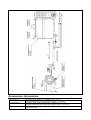
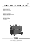
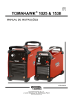
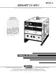
Figure B
Figure B: Machine Assembly (Rear side)
Item
1
2
3
4
5
6
7
8
9
10
11
18
19
Description
REAR PANEL
REAR PANEL
MAINS CORD without PLUG -5m (4x6mm2)
MAINS CORD without PLUG -5m (4x10mm2)
CABLE BOX
CABLE BOX
CAMP
CAMP
FUSE F1 (6,3A, 400V)
FUSE SOCKET
FUSE CAP
HOLE PLUG
CHAIN SUPPORT
PANEL
SHELF
WIRING HARNESS (SECONDARY VOLTAGE)
WIRING HARNESS (MAIN VOLTAGE)
Part Number
R-8040-031-1/08R
R-3040-129-1/08R
R-5041-026-1R
R-5041-121-1R
1361-599-665R
1361-599-250R
1361-599-633R
1361-599-620R
1158-660-008R
1158-632-032R
1158-632-033R
1361-599-058R
C-2631-407-1/08R
D-3721-403-2/08R
R-3019-042-1/08R
R-7040-034-1R
R-7040-036-4R
3
QTY
1
1
1
1
1
1
1
1
1
1
1
1
1
1
1
1
1
1
X
y
X
y
X
y
X
y
X
X
X
X
X
X
X
X
X
2
y
X
y
X
y
X
y
X
X
X
X
X
X
X
X
X
X
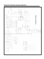
Electrical Schematic, Esquema Eléctrico
4
Accessories, Accessórios
K10347-PG-xM
K10347-PGW-xM
K14009-1
Source/wire feeder cable (gas). Available in 5, 10 or 15m.
Fonte/cabo alimentador de fio (gás). Disponível em 5, 10 ou 15m.
Source/wire feeder cable (gas and water). Available in 5, 10 or 15m.
Fonte/cabo alimentador de fio (gás e água). Disponível em 5, 10 ou 15m.
CO2 Socket Kit.
Kit de encaixe CO2.
5