1
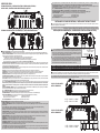
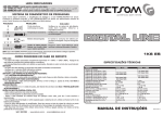
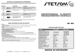
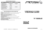
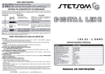
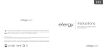
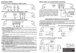
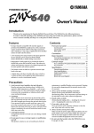
SISTEMA DE DIAGNÓSTICO DE PROBLEMAS / DIAGNOSTIC GUIDE
Caso ocorra algum problema, o amplificador irá desligar e o LED VERMELHO/PROT irá piscar. Conforme o problema ocorrido, o LED
VERMELHO/PROT irá piscar um determinado número de vezes. Assim teremos um diagnóstico conforme a tabela abaixo:
In the eventuality of any problems, the amplifier will power down and the RED LED/PROT light will begin to blink. Depending on the problem, the
RED LED/PROT light will flash a certain number of times. The following table summarizes the diagnostics:
PISCADAS / NUMBER OF FLASHES
PROBLEMA / PROBLEMA
SOLUÇÃO / SOLUTION
Curto circuito ou sobrecarga na saída.
Verifique se os cabos do alto-falante estão bem isolados.
Observe a impedância mínima.
Output short circuit or overload.
Check to make sure the speaker cables are properly
isolated. Verify minimum impedance.
Temperatura excessiva.
Verifique se o aparelho está instalado em local arejado.
Overheating.
Make sure the equipment is installed in a well-ventilated
location.
Bateria descarregada.
É normal o consumo de bateria por período prolongado.
Faça a recarga da bateria.
When used for long periods, the battery will run down.
Recharge the battery.
Low battery.
Tensão de bateria perigosa.
Bateria com tensão maior que o máximo permitido.
Procure uma auto-elétrica para verificar o sistema
alternador / bateria.
Dangerous battery voltage.
A battery with higher voltage than allowed.
Have the battery and/or alternator checked by a
professional.
OBS: Caso o led VERMELHO/PROT pisque continuamente, desconecte os alto-falantes e religue o aparelho.
Se o problema persistir, procure a assistência técnica STETSOM.
NOTE: In the event that the RED LED/PROT light is flashing continuously, unplug the speakers and turn the equipment back on. If the problem
persists, contact STETSOM tech support.
DIGITAL LINE
COMO PROCEDER EM CASO DE DEFEITO / TROUBLESHOOTING
NÃO LIGA:
- Os cabos não estão conectados corretamente (terminais “+” +BAT, “-” GND e REM). Assegure-se que todas as conexões têm contato elétrico e
mecânico.
- Os fusíveis/disjuntores estão com defeito ou queimados. Efetue a troca, atenção no valor correto dos novos!
SEM SOM:
- Os cabos dos alto-falantes ou plugs RCA não estão conectados corretamente.
- Verifique se o controle LEVEL não está no mínimo.
- Verifique os ajustes dos filtros do amplificador.
SEM SOM / LED VERMELHO DE PROTEÇÃO PISCANDO:
- Vide “SISTEMA DE DIAGNÓSTICOS”.
- Os alto-falantes ou cabos estão com defeito, deste modo cheque os alto-falantes, cabos e conexões.
QUALIDADE DE SOM POBRE (DISTORÇÕES):
- Os alto-falantes estão sobrecarregados, diminua o nível e refaça o ajuste de nível (vide item 3 “DESCRIÇÃO GERAL”).
GRAVES FRACOS:
- Cabos de falantes (+) e (-) estão trocados, alto-falante fora de fase (vide item “INSTALAÇÃO DAS SAÍDAS DE ALTO-FALANTES”). Verifique o ajuste
do controle BASS (6).
RUÍDO DO MOTOR, BUZINA, PISCA, ETC:
- Utilize cabos supressivo nas velas de ignição.
- Utilize condensadores no alternador, buzina e ignição.
- Passe o cabo blindado de entrada longe de qualquer outro cabo, pois ele é mais sensível a interferências.
- Faça a ligação de alimentação (+12V) separada para o sistema de som. Utilize um fusível/disjuntor a 30 cm da bateria para proteção.
- Faça um bom aterramento do amplificador. Para isto remova a tinta do chassi do veículo no ponto desejado. Parafuse o fio utilizando um terminal terra.
Para proteger de oxidação, isole com tinta.
- Não faça loop com terra. Evite utilizar vários terras. Prefira a ligação estrela, com todos os terras partindo de um único ponto.
NO POWER
- The power cables are not connected correctly (terminals +BAT, GND and REM). Verify that all the connections have electrical and mechanical contact.
- The fuse/circuit breakers are defective or blown. Replace them, making sure that the replacements are the correct ones!
NO SOUND
- The speaker cables or RCA plugs are not connected correctly.
- Verify that the LEVEL control is at the lowest setting.
- Check the amplifier filter controls.
NO SOUND. RED LED PROT BLINKING:
- See diagnostic guide
- The speakers or cables are defective, so check speakers, cables and connections.
POOR SOUND QUALITY (DISTORTIONS):
- The speakers are overloaded. Decrease and readjust the volume level (see entry 3, “General Description”)
WEAK BASS:
- Speaker cables (+) and (-) are switched or the speaker is out of phase (see entry “Installing Speaker Output”). Also check BASS control adjustment.
ENGINE, HORN, TURN SIGNAL INTERFERENCE:
- Use suppressing/insulated cables on the spark plugs.
- Use capacitors on the alternator, horn and ignition.
- Run the shielded input cable away from any other cables, as they are particularly prone to interference.
- Install a separate power source (+12V) for the sound system. Use a fuse/circuit breaker 30 centimeters from the battery as the best precaution.
- Ground the amplifier properly. Remove paint from the chassis at the selected point, and connect the wire using a grounded terminal. In order to prevent
rust, insulate it with paint.
Do not loop the ground. Avoid using multiple grounds. If possible, use a star connection, in which all the grounds run from a single point.
1K EQ
ESPECIFICAÇÕES TÉCNICAS / TECHNICAL SPECIFICATIONS
MODELO / MODEL:
Número de Canais / Channels:
Potência / Power @ 13.8V Mono 1 Ohm:
Potência / Power @ 13.8V Mono 2 Ohms:
Potência / Power @ 13.8V Mono 4 Ohms:
Potência / Power @ 12.6V Mono 1 Ohm:
Potência / Power @ 12.6V Mono 2 Ohms:
Potência / Power @ 12.6V Mono 4 Ohms:
Impedância Mínima de Saída / Minimum Output Impedance:
Impedância de Entrada / Input Impedance:
Sensibilidade Mínima de Entrada / Input Sensitivity:
Distorção Harmônica Total / Total Harmonic Distortion:
Relação Sinal Ruído / Signal to Noise Ratio (SNR):
Resp. em Frequencia / Frequency Response (-3dB) @ 8 Ohms:
Crossover Low Pass:
Crossover High Pass:
EQ - BASS @ 45Hz:
EQ - MID BASS @ 270 Hz:
EQ - MID HIGH @ 2KHz:
Over CLIP:
Tensão de Alimentação / Power Supply:
Consumo c/ Sinal Musical / Consumption Music Signal(12,6V):
Consumo c/ Sinal BASS / Consumption BASS Signal (12,6V):
Dimensões / Dimensions (A x L x C mm):
Peso / Weight Kg:
1K EQ – 2 OHMS
1
1.150 Watts RMS
690 Watts RMS
1.000 Watts RMS
600 Watts RMS
2 OHMS
25K OHMS
0,2V
< 0,9 % THD
> 90 dB
10 Hz ~ 25 KHz
50 Hz ~ 25 KHz
10 Hz ~ 700 Hz
±10dB
±10dB
±10dB
15% + Potência / Power
9,5 ~ 15 V
1,0 ~ 46 A
1,0 ~ 92 A
64 x 260 x 170
1,7
1K EQ – 1 OHM
1
1.330 Watts RMS
830 Watts RMS
1.120 Watts RMS
730 Watts RMS
1 OHM
26K OHMS
0,2V
< 0,9 % THD
> 90 dB
10 Hz ~ 25 KHz
50 Hz ~ 25 KHz
10 Hz ~ 700 Hz
±10dB
±10dB
±10dB
15% + Potência / Power
9,5 ~ 15 V
1,0 ~ 55 A
1,0 ~ 100 A
64 x 260 x 170
1,7
MANUAL DE INSTRUÇÕES / INSTRUCTION MANUAL
SAC: 30031900 - www.stetsom.com.br - [email protected]
JAN/2015 - R1
that a protective fuse or circuit breaker be used on this cable at a distance of 30 cm from the battery. The fuse or circuit breaker should be, at
minimum, equal to the max current consumption value caused by playing musical signals (see technical specifications table).
15) REM - REMOTE CONTROL: Connect the REM terminal to the electric antenna output of the CD/MP3 player. This will cause the amplifier to turn on
automatically when you turn on your CD/MP3 player. A cable with a gauge of .5mm² is adequate.
16) “- “ GROUND CONNECTION: Use a cable with a gauge of at least 21mm². Connect the cable to the chassis of the vehicle.
(Note: always connect the GND wire [-] of the CD player—or other equipment—to the same ground point.)
18) POWER LED (BLUE) : This indicator LED will light up when it is activated by the remote control signal from the CD/MP3 player.
19) PROT LED (RED): This LED will light up for the following reasons (see the diagnostic table on the back cover):
a) Short circuit in the speakers
c) Low battery voltage
b) Excessive temperature
d) High battery voltage
20) CLIP LED (RED): This LED will light up when the signal begins to suffer distortion.
DESCRIÇÃO GERAL
ENTRADA DE ÁUDIO, CONTROLES E SAÍDA DE ÁUDIO AMPLIFICADA /
AUDIO INPUT, CONTROLS AND AMPLIFIED AUDIO OUTPUT
18
H.P.F.
40Hz
L.P.F.
80Hz 70Hz 160Hz
BASS
0dB
20
19
MID BASS MID HIGH
0dB
OVER CLIP
0dB
10Hz 700Hz 50Hz 25KHz -10dB +10dB -10dB +10dB -10dB +10dB
ON
ON OFFOFF
INSTALANDO OS CABOS DE ENTRADA / INSTALLING THE INPUT CABLES
SPEAKER
1
2
3
4
5
6
7
8
10
9
11
ENTRADA DE VENTILAÇÃO E ALIMENTAÇÃO / VENT AND POWER SUPPLY
Para a ligação de entrada, utilize cabos blindados com conectores tipo RCA nas extremidades. Utilize cabos de boa qualidade, próprios para áudio,
para evitar a captação de ruídos indesejados.
For the input connection, use shielded cables with RCA plugs. Use quality cables, specific for audio, to avoid interference from unwanted noise sources.
(Recomendamos os Cabos RCA com Blindagem Tripla - STETSOM) / (We recommend the RCA cables with Triple shielding - STETSOM)
INSTALAÇÃO DA ALIMENTAÇÃO / POWER SUPPLY INSTALLATION (BATTERY)
POWER
POWER
12
13
14
15
16
17
1/11/12/17) VENTILAÇÃO: Permite a saída do ar aquecido do amplificador.
2) INPUT - ENTRADA RCA: Esta entrada deverá receber o sinal através de um cabo RCA que deverá estar conectado à saída RCA do CD/MP3-Player.
3) LEVEL - CONTROLE DE NÍVEL: Controla o nível do sinal de entrada, permitindo uma regulagem adequada a qualquer CD/MP3-Player existente no
mercado. Para fins práticos poderá ser regulado da seguinte forma:
a) no CD/MP3-Player, coloque um sinal musical qualquer e posicione o volume em 80% do máximo.
Por exemplo: se o máximo do volume do CD/MP3-player é 45 (100%), ajuste para 36 (80%).
b) no amplificador, a partir do LEVEL no mínimo, aumente gradativamente até o led de clipping começar a piscar.
c) retorne devagar o LEVEL até que o led apague completamente. (Observar o item 9 OVER CLIP)
4) HIGH PASS FILTER - FILTRO PASSA ALTA: Proporciona um corte nos sons de baixa freqüência (subsônicos). Este filtro é muito útil quando se utiliza
alto-falantes do tipo woofers. Nestes casos, os woofers não são capazes de reproduzir os subsônicos, podendo até danificar dependendo da potência e
música utilizada. Sua regulagem varia de 10Hz a 700Hz.
5) LOW PASS FILTER - FILTRO PASSA BAIXA: Este controle varia a freqüência de corte do filtro dos canais (crossover) de 50Hz a 25KHz. Este filtro
permite passar apenas os sons abaixo da freqüência de corte.
6) BASS: Este controle proporciona ganho/atenuação de ±10dB nas frequências de som graves. Frequência central de 45Hz.
7) MID-BASS: Este controle proporciona ganho/atenuação de ±10dB nas frequências de som médio-graves. Frequência central de 270Hz.
8) MID-HIGH: Este controle proporciona ganho/atenuação de ±10dB nas frequências de som média-alta. Frequência central de 2KHz.
9) OVER CLIP - ON / OFF: Com esta chave ligada, o LED de Cliping acenderá com 15% mais de potência final.
10) SAÍDA PARA ALTO-FALANTES: Esta saída é MONO. Cuidado com a polaridade correta das conexões com os alto-falantes e verifique a impedância
mínima permitida nesta saída. Utilize cabos de no mínimo 4 mm².
13) COOLER: Este ventilador irá funcionar de acordo com o volume do CD/DVD/MP3-Player, ou seja, quanto maior for o volume, maior será a velocidade
do ventilador. Sistema de ventilação controlado por áudio. FAN CONTROLLED BY AUDIO.
14) “+” +BAT - ALIMENTAÇÃO POSITIVA: Conecte o terminal ( “+” +BAT) ao pólo positivo da bateria (+12V) com um cabo de no mínimo 21,0mm². É
extremamente importante que seja utilizado um fusível ou disjuntor de proteção neste cabo a uma distância máxima de 30 cm da bateria. O
fusível ou disjuntor deverá ser no mínimo igual ao valor máximo de corrente consumida com sinal musical (vide tabela de especificações
técnicas).
15) REM - ACIONAMENTO REMOTO: Conecte o terminal REM à saída para antena elétrica do seu CD/MP3-Player. Assim quando ligar seu CD/MP3Player, o amplificador automaticamente ligará. Um cabo de 0.5 mm² é suficiente.
16) “-” CONEXÃO DE TERRA: Utilize cabo de no mínimo 21,0mm². Conecte o cabo no chassi do veículo.
OBS: sempre ligue o fio GND ( - ) do CD-Player, ou outros aparelhos no mesmo ponto.
18) POWER LED (AZUL): O led indicador acenderá quando o aparelho for acionado pelo sinal remoto vindo do CD/MP3-player.
19) PROT LED (VERMELHO): O Led acenderá nas seguintes situações (Vide Tabela de diagnósticos “Contra Capa”):
a) Curto-circuito nas saídas de alto-falantes
c) Baixa tensão da bateria
b) Temperatura acima da permitida.
d) Alta tensão da bateria
20) CLIP LED (VERMELHO): O Led acenderá quando o sinal de saída começar a distorcer.
1/11/12/17 VENTS: Allows for the removal of warm air from the amplifier.
2) INPUT – RCA INPUT: This input should receive the signal through an RCA cable connected to the output of the CD/MP3 player.
3) LEVEL – LEVEL CONTROL: Controls the input signal level, allowing for proper control of any CD/MP3 player currently on the market. It can be regulated
as the following:
a) on the CD/MP3 player, play any musical signal up to 80% volume (ie. If the maximum volume on the player is 45 [100%], adjust to 36 [80%]).
b) on the amplifier, beginning at the lowest LEVEL, gradually increase until the clipping LED begins to flash.
c) slowly decrease the LEVEL until the LED goes off. (see entry 9 OVER CLIP)
4) HIGH PASS FILTER: Allows cut off of low frequency (subsonic) signals. This filter is very useful for woofer-type speakers. In these cases, the woofers are
not capable of reproducing subsonic frequencies, and these subsonic frequencies may even cause damage depending on the volume and the music
played. It is regulated from 10Hz to 700Hz).
5) LOW PASS FILTER: This control varies the cut off frequency from 50Hz to 25KHz.This filter allows to pass only sounds beneath the cut frequency.
6) BASS: This control provides gain/attenuation of ±10dB in low frequency. Central frequency is 45Hz.
7) MID-BASS: This control provides gain/attenuation of ± 10dB in mid-low frequency. Central frequency is 270 Hz.
8) MID-HIGH: This control provides gain/attenuation of ±10dB in mid-high frequency. Central frequency is 2KHz.
9) OVER CLIP – ON/OFF: With this key turned on, the clipping LED will light up at 15% more final capacity.
10) SPEAKER OUTPUT: This output is MONO. Be careful of maintaining the correct polarity of the connections between the speakers and check the
minimum impedance of this output. Use cables with a minimum gauge of 4 mm² .
13) COOLER: This fan will operate according to the volume of the CD/DVD/MP3 player. The higher the volume, the higher speed at which the fan will run.
The ventilation system is controlled by audio. FAN CONTROLLED BY AUDIO.
14) “+” +BAT: Connect the terminal (“+” +BAT) to the positive terminal of the battery (+12V) with a minimum gauge of 21mm². It is extremely important
Para a instalação da alimentação, utilize cabos com bitola de 21mm². O cabo positivo
devera vir direto da bateria, com um fusível ou disjuntor de proteção localizado a 30cm da
bateria. O cabo negativo deverá ter a mesma bitola do positivo, e parafusado no chassi do
veiculo, tomando-se o cuidado de evitar tinta e ferrugem que poderão impedir a passagem da
corrente elétrica, causando perda de potência e ruídos no som.
In order to install the power supply, use cables with a gauge of 21mm². The positive cable
should come straight from the battery, with a fuse or protective breaker 30cm from the battery.
The negative cable should have the same gauge as the positive cable, and should be screwed
to the chassis of the vehicle, taking caution to avoid paint and rust. These may interfere with the
flow of the electrical current, causing loss of power and interference in the sound.
ACIONAMENTO REMOTO
REMOTE CONTROL
DISJUNTOR ou MÁX
FUSÍVEL: 40A 30 cm
FUSE or
CIRCUIT BREAKER
BATERIA
BATTERY
12V
CHASSI
ATENÇÃO: O USO DO DISJUNTOR OU FUSÍVEL EXTERNO É OBRIGATÓRIO, JÁ QUE O AMPLIFICADOR NÃO POSSUI FUSÍVEL INTERNO.
ATTENTION: THE USE OF THE FUSE OR BREAKER IS REQUIRED, SINCE THIS AMPLIFIER HAS NO INTERNAL FUSES.
INSTALAÇÃO DA SAÍDA DE ALTO-FALANTES / INSTALLATION OF THE SPEAKER OUTPUTS
Os cabos dos alto-falantes deverão ser polarizados (marcados) para facilitar a identificação de positivo e negativo. A bitola mínima é de 4mm².
Mantenha os cabos dos alto-falantes bem isolados. Cuidado com partes metálicas que podem danificar a isolação dos cabos.
The speaker cables should be polarized (marked) in order to facilitate identifying which is positive and which is negative. Minimum gauge is 4mm².
Keep the cables well insulated, and avoid metal parts, as these may damage the insulation.
H.P.F.
40Hz
COM 2 ALTO-FALANTES
WITH 2 SPEAKERS
L.P.F.
80Hz 70Hz 160Hz
BASS
0dB
MID BASS MID HIGH
0dB
OVER CLIP
0dB
10Hz 700Hz 50Hz 25KHz -10dB +10dB -10dB +10dB -10dB +10dB
ON
ON OFFOFF
SPEAKER
1K EQ - 2 OHMS: 2 x 4 OHMS
1K EQ - 1 OHM: 2 x 2 OHMS
H.P.F.
40Hz
COM 4 ALTO-FALANTES
WITH 4 SPEAKERS
L.P.F.
80Hz 70Hz 160Hz
BASS
0dB
MID BASS MID HIGH
0dB
OVER CLIP
0dB
10Hz 700Hz 50Hz 25KHz -10dB +10dB -10dB +10dB -10dB +10dB
ON
ON OFFOFF
SPEAKER
1K EQ - 2 OHMS: 4 x 8 OHMS
1K EQ - 1 OHM: 4 x 4 OHMS