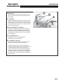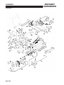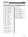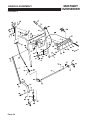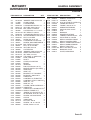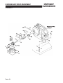
1
524583-PT (rev.3)
Safety, Operation, Parts, Maintenance & service Manual
Manual de segurança, peças, manutenção e assistência
Mataway Overseeder
Model: 544873B
Modelo: 544873B
WARNING: If incorrectly used this machine can cause severe
injury. Those who use and maintain this machine should be
trained in its proper use, warned of its dangers and should
read the entire manual before attempting to set up, operate,
adjust or service the machine.
AVISO: Esta máquina pode causar ferimentos graves se for
utilizada incorrectamente. A pessoa responsável pela sua
utilização e manutenção deve ser previamente instruída para
a sua utilização correcta, avisada sobre os perigos que ela
pode causar e deve ler todo o manual antes de tentar
preparar, conduzir, afinar ou reparar a máquina.
GB
PT
English
Portuguese
RJ 100 / 032003
© 2003, Ransomes Jacobsen Limited. All Rights Reserved
© 2003, Ransomes Jacobsen Limited. Todos os direitos reservados
MATAWAY
OVERSEEDER
IMPORTANT MESSAGE
Thank you for purchasing this Ryan product. You have purchased a world class product, one of the best designed
and built anywhere.
This machine comes with a Technical Manual containing safety, operation, parts, maintenance and service
information. The useful life and good service you receive from this machine depends to a large extent on how well
you read and understand this manual. Treat your machine properly, lubricate and adjust it as instructed, and it will
give you many years of reliable service.
Your safe use of this Ryan product is one of our prime design objectives. Many safety features are built in, but
we also rely on your good sense and care to achieve accident-free operation. For best protection, study the manual
thoroughly. Learn the proper operation of all controls. Observe all safety precautions. Follow all instructions and
warnings completely. Do not remove or defeat any safety features. Make sure those who operate this machine
are as well informed and careful in its use as you are.
See a Ryan dealer for any service or parts needed. Ryan service ensures that you continue to receive the best
results possible from Ryan’s products. You can trust Ryan replacement parts because they are manufactured with
the same high precision and quality as the original parts.
Ryan designs and builds its equipment to serve many years in a safe and productive manner. For longest life, use
this machine only as directed in the manual, keep it in good repair and follow safety warnings and instructions.
You'll always be glad you did.
Jacobsen, a Textron Company
One Bob Cat Lane
Johnson Creek, WI 53038-0469
TABLE OF CONTENTS
FIGURES
PAGE
SAFETY ......................................................................................................................................................... 2
SAFETY AND OPERATION DECALS ............................................................................................................ 3
SET-UP .......................................................................................................................................................... 4
CONTROLS ................................................................................................................................................... 5
OPERATION ............................................................................................................................................... 6-9
SERVICE ................................................................................................................................................. 10-23
STORAGE .................................................................................................................................................... 24
TRANSPORTING ......................................................................................................................................... 25
SPECIFICATIONS ........................................................................................................................................ 26
PARTS SECTION ......................................................................................................................................... 27
CHASSIS ............................................................ FIGURE 1 .................................................................. 28, 29
HANDLE ASSEMBLY ......................................... FIGURE 2 .................................................................. 30, 31
CLUTCH ASSEMBLYAND CONTROL ............... FIGURE 3 .................................................................. 32, 33
ENGINE AND DRIVE ASSEMBLY ...................... FIGURE 4 .................................................................. 34, 35
TRANSMISSION ................................................ FIGURE 5 .................................................................. 36, 37
GUARDS ............................................................ FIGURE 6 .................................................................. 38, 39
HOPPER DRIVE ................................................ FIGURE 7 .................................................................. 40, 41
HOPPER FRAME ............................................... FIGURE 8 .................................................................. 42, 43
HOPPER AND DISC ASSEMBLY ....................... FIGURE 9 .................................................................. 44, 45
REEL .................................................................. FIGURE 10 ................................................................ 46, 47
3-2003
GB-1
MATAWAY
OVERSEEDER
SAFETY
NOTICE !!!
Unauthorized modifications may present extreme
safety hazards to operators and bystanders and
could also result in product damage.
Jacobsen, a Textron Company strongly warns
against, rejects and disclaims any modifications,
add-on accessories or product alterations that are
not designed, developed, tested and approved by
Jacobsen Engineering Department. Any Jacobsen
product that is altered, modified or changed in any
manner not specifically authorized after original
manufacture–including the addition of “after-market”
accessories or component parts not specifically
approved by Jacobsen–will result in the Jacobsen
Warranty being voided.
Any and all liability for personal injury and/or property
damage caused by any unauthorized modifications,
add-on accessories or products not approved by
Jacobsen will be considered the responsibility of the
individual(s) or company designing and/or making
such changes. Jacobsen will vigorously pursue full
indemnification and costs from any party responsible
for such unauthorized post-manufacture
modifications and/or accessories should personal
injury and/or property damage result.
This symbol means:
ATTENTION!
BECOME ALERT!
Your safety and the safety of others is involved.
Signal word definitions:
The signal words below are used to identify levels of
hazard seriousness. These words appear in this
manual and on the safety labels attached to Jacobsen
machines. For your safety and the safety of others,
read and follow the information given with these
signal words and/or the symbol shown above.
DANGER indicates an imminently hazardous
situation which, if not avoided, WILL result in death
or serious injury.
WARNING indicates a potentially hazardous situation
which, if not avoided, COULD result in death or
serious injury.
CAUTION indicates a potentially hazardous situation
which, if not avoided, MAY result in minor or moderate
injury. It may also be used to alert against unsafe
practices or property damage.
CAUTION used without the safety alert symbol
indicates a potentially hazardous situation which, if
not avoided, MAY result in property damage.
MODEL NUMBER: This number appears on
sales literature, technical manuals and price lists.
SERIAL NUMBER: This number appears only
on your mower. It contains the model number
followed consecutively by the serial number. Use
this number when ordering parts or seeking
warranty information.
GB-2
MATAWAY
OVERSEEDER
SAFETY AND OPERATION DECALS
Throttle Control
Clutch Control
Fast
Throttle
Both drive and reel clutches
DISENGAGED (control is pulled
back)
Drive clutch ONLY engaged
(control is pushed forward)
Engine Stop
Slow
Both drive and reel clutches
engaged (lever is pulled
back to knob, then control is
pushed forward)
Sound Level
Operator should wear hearing protection if operating
the machinery for extended periods of time (longer
than 4 hours).
Sound Level
Cutting Height Adjustment
Turn the adjustment screw clockwise
to raise the cutting height.
Turn the adjustment screw
counterclockwise to lower the
cutting height.
Safety Warnings
Operating Instructions
To prevent injury, the operator must be familiar with
the operation of this machinery and fully aware of safe
operating procedures.
Hands or feet may be
severely injured or
severed if placed beneath
the unit while running.
Bystanders should keep a
safe distance from the
machine while it is
running.
Keep hands away
from moving parts.
Read and understand the
operator's manual
Lift Control
Safety shieds should
remain in place while
running the machine.
Hands may become
entangled in belts.
Disconnect the spark plug
wire and read the manual
before performing any
service or maintenance on
the unit.
Push down on the
handle to lower the reel
Pull the handle up
to raise the reel
GB-3
SET-UP
MATAWAY
OVERSEEDER
Do not operate this equipment until you have
read the CONTROLS and OPERATION
sections of this manual thoroughly.
2. Check the oil level in the transmission. Level
should be up to the plug opening in the side of
the case. Add EP 80-90 gear lube if required.
Case capacity is 1/2 pint (.4L).
To prevent injury, use an adequate lifting
device (i.e., hoist, or fork lift) to remove unit
from pallet.
3. Check engine oil level. Refer to the engine
manual for the appropriate amount and weight of
oil.
1. Remove and discard banding attaching the
Mataway Overseeder to the pallet, and remove
unit from pallet.
4. Inspect the chassis for proper lubrication. When
lubricating, be sure to wipe the lubrication fittings
before and after lubrication.
Banding is under tension and may snap back
when cut. Wear eye protection and stay clear
when cutting the band.
GB-4
MATAWAY
OVERSEEDER
CONTROLS
THROTTLE (A)
Move throttle lever forward to increase engine
speed. Move the lever all the way back to stop
the engine.
LIFT LEVER (B)
Raises and lowers the frame mounted reel. Pull
the lever back and down to lower the reel and to
start seed flow from the hopper. Pull the lever up
and forward until it locks over center to raise the
reel and stop seed flow.
OPERATOR PRESENCE LEVER (C)
Must be held against the handle bar whenever
the clutch control is engaged or the engine will
stall (the engine can be started without holding
the operator presence lever, if the clutch control
is disengaged).
CLUTCH CONTROL (D)
Engages the clutch for both the drive
transmission and reel rotation.
REEL CONTROL LEVER (E)
Must be pulled back against the clutch control
handle for the reel clutch to be engaged.
Pull the Reel Control Lever back against the
clutch control and push the clutch control forward
to engage both the drive clutch and the reel
clutch. Push the clutch control forward without
pulling back the reel control lever to engage the
drive clutch ONLY. Pull the clutch control all the
way back until it locks over center to disengage
both clutches.
GB-5
OPERATION
Gasoline is extremely flammable and highly
explosive under certain conditions. Always
stop the engine and do not smoke or allow
open flames or sparks when refueling. BE
SURE to install fuel cap after refueling.
Remove fuel cap slowly. Fuel tank may be under
pressure and could cause personal injury from
spraying.
STARTING THE ENGINE
Before starting engine, check engine oil level. Fill
if necessary following the engine manufacturer's
recommendation for the type and amount of oil
required.
Fill fuel tank with appropriate fuel recommended
by the engines manufacturer.
1. Make sure the lift lever is in the raised position.
2. Make sure the clutch control is disengaged
(engine will not start if the clutch control is
engaged).
3. Move the throttle lever midway between fast and
slow.
4. Use the choke as required to start a cold engine.
Choke control F is located on the front of the
engine.
5. Stand at side of unit placing left foot on top of
housing and slowly pull the recoil starter until just
past compression. Return starter handle, pull
firmly with a smooth, steady motion to start.
GB-6
MATAWAY
OVERSEEDER
NEVER start or run the engine inside where
exhaust fumes can collect. Carbon monoxide
present in the exhaust is an odorless and deadly
gas.
DO NOT operate equipment without shields in
place. DO NOT make adjustments or perform
any maintenance while the engine is running.
Immediately replace any warning decal which
becomes illegible.
MATAWAY
OVERSEEDER
OPERATION
DEPTH ADJUSTMENT
Loosen the locking nut. Turn the adjusting screw
G clockwise (down) to raise reel from the turf, and
turn the adjusting screw counterclockwise (up) to
lower reel into the turf. Tighten locking nut H after
each reel adjustment.
Low tire pressure may cause uneven reel
penetration. Correct tire pressure should be
maintained to eliminate this possibility (refer to the
Tire Pressure section of this manual, for
recommended tire pressure).
NOTE: The factory reel depth setting gives a
maximum of 1/4" (6 mm) turf penetration on
level terrain, and a reel to ground clearance
of 1-1/2" (38 mm) when reel lift lever is in the
transport (raised) position. Do not operate at
turf depths exceeding 1/4" (6 mm).
Never cross hard surfaces or objects
(sidewalks, driveways, stepping stones etc.)
with reel blades down and/or engaged.
Increasing the depth of the reel blades will
decrease ground clearance when the reel is
in the raised position.
After adjusting to desired cutting depth, test run
the unit to check for desired blade penetration.
GB-7
OPERATION
MATAWAY
OVERSEEDER
OVERSEEDER OPERATION
1. Adjust reel to desired cutting depth, not to exceed
1/4" (6mm) maximum.
NOTE: Cutting depth exceeding 1/4" (6 mm) may be
too deep for most seed and may prevent
germination.
2. Make a test run to check for desired blade
penetration.
3. Set the feed control cam A on the hopper
according to the "Seed Feed Chart" located
inside the hopper cover. Fill the hopper with
seed.
4. Start the engine. Compress and hold the
operator presence lever.
5. Pull back on the reel control lever and push the
clutch control forward to engage both the reel and
drive clutches. Adjust the throttle to the
operator's desired walking speed.
6. Lower the reel after the unit is in motion, the
seed gate opens automatically as the reel is
lowered.
Before operating, check area to be worked
and remove any object(s) which may present
a safety hazard and/or damage the equipment.
NOTE: To prevent damage to the turf, the unit
should be in motion and the clutch control
engaged before lowering reel onto the turf.
To prevent injury due to rotating blades, never
place hands or feet beneath the equipment at
any time.
Never cross hard surfaces or objects (sidewalks,
driveways, stepping stones, etc.) while the reel is
down and/or engaged.
7. After each pass across the turf, raise the reel,
disengage the clutch control and position the unit
manually for the next pass (this will help prevent
damage to the turf). Make all passes across the
turf at uniform speed. Slightly overlap the area
previously seeded to ensure complete coverage.
GB-8
To prevent injury from thrown blades, never
operate equipment with reel blades that are
cracked, badly bent, missing, or in any
abnormal condition.
MATAWAY
OVERSEEDER
OPERATION
CROSSHATCH OVERSEEDING
Making two passes over the same area with the
feed cam set at half the desired seed flow rate will
provide faster fill in.
Make the first set of passes (parallel to each other)
over the area in the normal manner but at half the
seed feed rate.
Cover the same area again, but make the second
set of passes at a 45o angle across the first set of
passes, again at half the seed rate.
This will lay down the seed in a diamond pattern,
resulting in better distribution and faster cover after
germination.
DETHATCHING
For the de-thatching operation, make sure there is
no seed in the hopper, seed gate will still open
during use.
Whenever possible, a few test runs should be
made on turf similar to where the unit will be used.
This will allow preliminary adjustments to be made
before entering greens (etc.) and help eliminate
the possibility of turf damage due to
misadjustments. Low tire pressure may cause
uneven reel penetration. Correct tire pressures
should be maintained to eliminate this possibility
(refer to the Tire Pressure section of this manual,
for recommended tire pressure).
1. Start the engine. Compress and hold the
operator presence lever.
2. Pull back on the reel control lever and push the
clutch control forward to engage both the reel and
drive clutches. Adjust the throttle to the
operator's desired walking speed.
3. Lower the reel after the unit is in motion, the
seed gate opens automatically as the reel is
lowered.
NOTE: To prevent damage to the turf, the unit
should be in motion and the clutch control
engaged before lowering reel onto the turf.
4. After each pass across the turf, raise the reel,
disengage the clutch control and position the unit
manually for the next pass (this will help prevent
damage to the turf). Make all passes across the
turf at uniform speed.
Before operating, check area to be worked and
remove any object(s) which may present a
safety hazard and/or damage the equipment.
To prevent injury due to rotating blades, never
place hands or feet beneath the equipment at
any time.
To prevent injury from thrown blades, never
operate equipment with reel blades that are
cracked, badly bent, missing, or in any
abnormal condition.
Never cross hard surfaces or objects (sidewalks,
driveways, stepping stones, etc.) while the reel is
down and/or engaged.
GB-9
SERVICE
To keep the Mataway Overseeder in good
operating condition, proper maintenance and
immediate repair of any damaged part is
necessary. Perform the following services, and
follow procedures for proper storage.
When replacement parts are required, use
genuine RYAN parts or parts with equivalent
characteristics, including type, strength and
material. Failure to do so may result in
product malfunction and possible injury to
the operator and/or bystanders.
PREVENTIVE MAINTENANCE
After each days use:
1. Wash unit with water after engine has cooled.
2. Check blades for damage (cracks, broken
blades, etc.) replace if necessary. Make sure
blades are free of debris and apply a light coat of
oil to the blades to help prevent rust (any motor
oil will work effectively).
LUBRICATION
The Mataway Overseeder has 7 lubrication fittings.
1. Wipe off each fitting before and after lubrication.
2. Use a good quality Lithium based lubricant.
3. Lubricate equipment after every 8 hours of use
and before long storage periods.
GB-10
MATAWAY
OVERSEEDER
Any warning decal that becomes illegible should
be replaced immediately.
Wear protective eye equipment when using
hammer, chisels, punches and drills.
Carbon monoxide present in the exhaust is an
odorless and deadly gas. Provide enough
ventilation. Never start or run the engine inside
where exhaust fumes can collect.
Stop engine and let cool before servicing or
making adjustments around the engine area.
Use adequate lifting device to raise unit. Use
appropriate jack stands to support unit.
3. Check engine oil level and air cleaner for dirt and/
or obstructions. Service according to engine
manual recommendations.
4. Check transmission case for proper oil level. The
case holds 1/2 pint (.4L) when full. Use EP90w
Oil.
5. Keep all belts free from dirt and oil.
MATAWAY
OVERSEEDER
SERVICE
TIRE PRESSURE
Keep the tires to the recommended pressure.
Improper inflation will shorten the life of the tires
and cause unsatisfactory operation.
Tires......................................4.10 / 3.50 - 4, 2-ply
Tire Pressure.........24 to 26 PSI (165 to 179 kPa)
Due to low air volume of tires, over-inflation
can be reached in a matter of seconds. To
prevent explosion, check air pressure with
air gauge before filling the tire. Fill to
recommended air pressure, and Do Not
exceed the recommended pressure.
CHAIN REPLACEMENT
1. Remove the belt guards and the hopper drive
belt.
2. Loosen the drive chain idler sprocket B.
3. Remove connecting link C and chain D.
4. Install new chain and connecting link.
5. Adjust the idler sprocket to allow approximately 1/
8" (3 mm) to 1/4" (6 mm) of play in the chain
(check for play on the straight section of chain
opposite the sprocket). Tighten the idler sprocket
hardware.
NOTE:
Proper chain tension is essential. A tight
chain will impose excessive bearing loads. A
loose chain will cause noisy operation and chain
pulsations, which may result in irregular sprocket
speed and abnormal chain and sprocket wear.
6. Lubricate the fitting on the idler sprocket.
7. Reinstall the hopper drive belt and make sure all
guards and covers are in place before using the
unit.
GB-11
SERVICE
REEL REMOVAL AND INSTALLATION
1. Tilt the unit forward and support the rear of the
chassis with jack stands.
Use adequate jack stands when supporting
the unit. Failure to do so may result in
personal injury.
2. Remove the lower belt guard from under the
chassis by removing the screw at the front of the
guard and swinging the guard down.
3. Release the reel clamps E on both sides of the
unit by pulling the clamp levers back.
4. Lower the left end of the reel and remove the
three belts from the pulley at the right end.
Remove the reel. If the blades need to be
replaced, refer to the section on reel blade
replacement.
5. Reinstall the reel in the reverse order of removal.
When reinstalling the reel, make sure the reel
clamps lock "over-center". Failure to do so
may allow the reel to work loose causing
injury to the operator and/or bystanders.
GB-12
MATAWAY
OVERSEEDER
MATAWAY
OVERSEEDER
SERVICE
REEL BLADE REPLACEMENT
NOTE:
Note how the blades and spacers are
arranged on the reel and the direction of the
blades before disassembly so that it can be
reassembled in the same manner.
1. On the end of the shaft opposite the pulley,
loosen the set screw in the locking collar A on the
reel shaft. Insert a punch in the small hole on the
collar and use a hammer to tap the collar
clockwise until it's loose (approx. 1/4 turn).
Remove the collar and remove the pillow block
and bearing B.
2. Loosen the socket head screw C in the reel nut D
and remove the reel nut from the shaft.
3. Slide the blades and spacers off of the shaft.
4. Reassemble the reel with new blades.
NOTE: When reassembling the reel, it is important to
start and end with a spacer. DO NOT assemble
with a blade next to the shaft nut.
5. Make sure the socket head screw C in the reel
nut D is just "snug" or about 1 to 2 ft.-lb.
(1.5 - 3 N·m). Screw the nut onto the reel shaft
and torque to 80 + 10 ft.-lb. (108 + 13 N·m).
Make sure enough spacers are used to prevent
the reel nut from contacting the shoulder of the
hexagonal section of the shaft. Tighten the
socket head screw to 10 to 12 ft.-lb. (13-16 N·m).
6. Install the pillow block with bearing B on the
shaft. Slide the pillow block on until the outside
edge of the block is 5/8" (16mm) from the end of
the shaft.
7. The pillow block B must also be perpendicular to
the shaft. To check this, hold a ruler G against
the first blade H and across the edge of the pillow
block. Rotate the pillow block by hand. If the
edge of the pillow block does not appear to
wobble (move back and forth) the pillow block is
perpendicular.
8. Install the locking collar against the bearing by
tapping it counterclockwise approx. 1/4 turn and
tightening the set screw.
9. After the reel has been reinstalled (refer to the
section on Reel Removal And Installation)
readjust the blade height.
10. With the unit on a level surface, lower the reel,
loosen the locking nut and turn the depth
adjusting screw until the blades just touch the
ground.
11. Raise the reel and turn the adjustment screw
counterclockwise 3-1/2 turns to achieve
1/4" (6 mm) blade penetration.
NOTE: This unit is designed for a maximum of
1/4" (6 mm) turf penetration. Some seeds will not
germinate at depths exceeding 1/4", and turf
penetration exceeding 1/4" will shorten belt life.
After 4 hours of use, check reel nut for proper
torque. The torque value for the reel nut is
80 ft.-lbs. + 10 ft.-lbs. (108 + 13 N·m).
GB-13
SERVICE
REEL-BELT AND DRIVE-BELT REPLACEMENT
NOTE:
Reel belts are serviced in matched sets
of three belts. When replacement is required,
always replace all three belts. It is a good idea to
replace all belts (drive and reel) on the unit at the
same time.
1. Remove the belt guards and the hopper drive
belt.
2. Tilt the unit forward and support the rear of the
chassis with jack stands.
Use adequate jack stands when supporting
the unit. Failure to do so may result in
personal injury.
3. Remove the lower belt guard from under the
chassis and take out the reel. Remove the jack
stands and lower the unit.
4. Loosen the set screw in the locking collar K on
the drive shaft. Insert a punch in the small hole in
the collar and use hammer to tap the collar
clockwise (opposite direction of engine rotation)
until it's loose (approx. 1/4 turn). Remove the
collar.
5. Remove the bolts H securing the mounting plate
L. Remove plate and the pillow block J (leave
the pillow block attached to the mounting plate).
6. Remove all three reel belts.
NOTE:
Inspect the drive belt to the transmission
after the reel belts have been removed.
Replacing the drive belt now will save work and
down time at a later date.
7. Install new belts (matched set of three).
8. Before reinstalling the mounting plate L, loosen
but do not remove the pillow block J.
9. Slide the pillow block bearing onto the shaft and
loosely mount the plate to the chassis. Adjust the
mounting plate L side-to-side so that there is no
side load on the drive shaft. Tighten the
mounting plate hardware H.
GB-14
MATAWAY
OVERSEEDER
MATAWAY
OVERSEEDER
SERVICE
10. Reinstall the locking collar against the bearing.
Tighten locking collar by rotating
counterclockwise on pillow block shoulder. Using
punch and hammer, lock collar into position.
Tighten set screw.
11 Adjust the pillow block up and down until it is
centered on the shaft. Tighten the pillow block
hardware.
12. Rotate the drive shaft by hand to make sure there
is no side load.
NOTE:
Excessive side load on the shaft may
cause engine crankshaft failure.
13. Check the reel belt pulley alignment. The
measurement A should be 5/8" (16mm). If
adjustment is required, loosen the set screw in
the pulley and move the pulley in or out on the
shaft.
NOTE:
The pulley is secured to the shaft by set
screw and key. It may need to be tapped with a
hammer for adjustment. Use a plastic, rubber,
lead or leather head hammer to avoid damaging
the pulley.
14. Support the unit on jack stands and reinstall the
reel and belt guard beneath the chassis.
Use adequate jack stands when supporting
the unit. Failure to do so may result in
personal injury.
15. Install the hopper belt and belt guards before
operating the unit.
NOTE:
Belts should be tight when the reel and
drive are engaged and loose enough to slip when
they are disengaged.
GB-15
SERVICE
ADJUSTMENT FOR REEL AND DRIVE BELTS
Over time, the belts will naturally need adjusting
due to the use of the equipment. Inspect belts
daily to ensure proper operation of the unit.
Before adjusting belts, make sure to:
1. Loosen the transmission mounting plate A and
chain idler sprocket hardware.
2. Clean the underside of chassis to allow
movement of the engine and loosen the engine
mounting hardware.
3. Loosen the hardware securing the mounting plate
B (supporting the reel drive pulley) and the pillow
block.
4. Loosen the set screw in the locking collar C on
the drive shaft. Insert a punch in the small hole in
the collar and use a hammer to tap the collar
clockwise (opposite direction of engine rotation)
until it's loose (approx. 1/4 turn).
5. Make sure the springs are in place on the drive
belt idler arm and the reel belt idler arm.
6. Slide transmission and mounting plate toward the
rear of unit as far as possible. Tighten
transmission mounting hardware.
7. Position engine so it is square with the chassis
and tighten either the two front or the two rear
mounting screws.
8. Engage the reel drive clutch. Measure the
distance between the reel drive belts and the
forward edge of the idler assembly belt stop.
Measurement D should be 3/4" (19 mm). If
necessary, reposition engine to obtain proper
dimension.
9. Engage the drive clutch. Measure the distance
from the top edge of the idler pulley F, to the top
edge of the drive belt G. The measurement E
should be 1-3/4" to 2" (44 to 51 mm).
10. If measurement is less than 1-3/4" (44 mm) slide
transmission forward until proper dimension is
obtained.
GB-16
MATAWAY
OVERSEEDER
MATAWAY
OVERSEEDER
SERVICE
11. If the measurement is over 2" (51 mm) slide the
engine forward to obtain correct measurement. If
the engine has to be moved, check the reel belt
measurement again for proper dimension.
NOTE:
Reel and drive belt adjustments are
guidelines only. The reel drive belts should
engage without slipping and disengage
completely. The drive belt should engage without
slipping and disengage so that the unit will not
creep.
12. Tighten engine and transmission mounting
hardware securely. Slide chain idler sprocket
against the drive chain until there is 1/8" to 1/4" (3
to 6 mm) play in the chain opposite the sprocket
and secure hardware.
13. Using a straight edge, align the belt drive pulley
on the transmission with the drive pulley on the
engine. Loosen the set screw on the
transmission pulley and slide it in or out to
achieve proper alignment.
14. Align the mounting plate L so that it is
perpendicular to the chassis and the pillow block
bearing is centered on the coupler shaft. Tighten
the two plate mounting screws H at the bottom of
the plate.
15. Align the pillow block bearing with the coupler
shaft so that there is no vertical or side load on
the shaft and tighten the pillow block mounting
hardware. Torque the pillow block screws to
25 ft.-lbs. (34 N·m).
16. Tighten locking collar K on engine coupler shaft.
Rotate collar counterclockwise on pillow block
shoulder. Using hammer and punch, lock collar
into position. Tighten set screw in collar K.
17. Engage reel drive clutch. Check the clearance
from the idler pulley M to the belt stop N bolted to
the mounting plate, clearance should be a
minimum of 1/16" (2 mm). If necessary, loosen
the belt stop hardware O and reposition it.
Tighten hardware.
GB-17
SERVICE
18. Check clutch control for positive over-center
action in disengaged position. Adjust rod length if
necessary.
19. To adjust rod length to achieve positive overcenter locking, loosen the jam nut on top of the
clevis at the bottom of the clutch lever.
20. Remove the cotter pin A and clevis pin B, and the
two bushings C on the control handle. Turn the
rod to shorten or lengthen the rod as required
and reattach the rod to the handle with the clevis
pin.
21. Double check to ensure over-center locking
action. When proper locking action is obtained,
completely assemble control handle and tighten
jam nut.
22. Engage and disengage clutch control lever
several times and check to see that belt stops
work properly. The belts should be held firmly,
but not pinched severely, with reel drive lever
disengaged.
NOTE:
Overtight belt stops will cause undo
wear on reel drive belts.
23. Belt stop tension on the reel belts can be
adjusted by loosening the screw D in the reel belt
idler assembly and screwing it in or out to adjust
the tension on the idler arm when it is in the
disengaged position.
24. Disengage the clutch lever. Check the tips of the
two belt stops E & F. The gap G should be a
minimum of 1/32" (1 mm) between the tips of the
stops. If necessary, loosen reel idler pivot plate
and adjust accordingly.
25. The belt stops should be perpendicular to the reel
belts and parallel to each other. Make sure reel
drive idler pulley is centered and aligned over reel
drive belts.
GB-18
MATAWAY
OVERSEEDER
MATAWAY
OVERSEEDER
SERVICE
HOOK AND CABLE ADJUSTMENT
1. Loosen the hardware securing the hook A. Slide
the hook in the slot so that it captures the reel
idler assembly when the clutch control is
disengaged. When only the drive clutch is
engaged, the hook should hold the reel idler
assembly back far enough that the reel belts will
not engage. Retighten the hook mounting
hardware.
2. After the hook has been adjusted. Loosen the two
jam nuts B at the top of the cable. Adjust the
bottom nut to take up any slack in the cable. Be
careful not to overtighten the cable or the hook
may not hold the reel idler assembly. Use the top
nut to lock the lower nut into place.
GB-19
SERVICE
HOPPER DRIVE PULLEY SPROCKET
ADJUSTMENT
With the belt covers removed, raise and lower the
reel using the Reel Lift Lever, and check to make
sure the sprocket C on the inside of the hopper
drive pulley properly engages the drive chain D
from the transmission.
1. If the pulley sprocket C does not align with the
chain D, the set screw in the drive sprocket E on
the transmission can be loosened, and the
sprocket moved in or out on its shaft to align the
chain with the pulley sprocket.
2. If the pulley sprocket is aligned with the chain but
does not engage the chain fully, raise the reel
and check the chain tension for the proper 1/8" to
1/4" (3 to 6mm) play.
3. If the chain tension is correct, lower the reel and
loosen the nut G on the hopper pulley adjustment
rod H until the sprocket C fully engages the
chain.
4. To make sure the pulley sprocket fully
disengages the chain, raise the reel, and check
for clearance F of approximately 1/8" (3 mm)
between the sprocket and chain.
GB-20
MATAWAY
OVERSEEDER
MATAWAY
OVERSEEDER
SERVICE
DISC ALIGNMENT
1. Tip unit forward and place on jack stands. Check
the disc/blade alignment by placing a straight
edge C against the concave side of the either the
fifth or sixth disc A and the corresponding blade
B on the reel. The straight edge should lie flat
against both disc and blade.
Use adequate jack stands when supporting
the unit. Failure to do so may result in
personal injury.
2. The discs can be aligned with the blades by
loosening the two locking collars just inside the
bearings at either end of the disc shaft. Loosen
the set screws and tap the collar clockwise (with
hammer and punch) to unlock, then move the
entire shaft until the discs align with the blades.
Lock the collars against the bearings and tighten
the set screws.
GB-21
SERVICE
TRANSMISSION GEAR REPLACEMENT
1. Remove the transmission from the unit.
2. Remove the sprocket, pulley and keys.
3. Remove the plug and drain the oil from the gear
case.
4. Remove the the remaining hardware. Take note
of which side is the input side and which is the
output side so that they can be reassembled
correctly. Using a soft hammer, tap case on the
tabs to break the seal, and pull halves E & F
apart.
5. Remove the input shaft A, output shaft B and
spacer C. Also remove the bearings D and
grease seals.
6. Install new bearings into both case halves.
DO NOT install new grease seals at this time.
INPUT SHAFT
7. Remove large double gear E, small gear F, key
G, and spacer H from input shaft J.
8. Check the input shaft for wear and replace if
necessary (if shaft needs to be replaced, install
the existing snap ring K on new shaft). If the
shaft is NOT replaced, remove any burrs from
keyways and/or shaft ends if necessary.
9. Replace bushings in the large double gear E (or
replace gear if necessary). When replacing
bushings, make sure they are flush with the edge
of the gear and that the oil holes on gear are
aligned.
10. Install the spacer H onto shaft against the snap
ring K. Install the large double gear E, with the
small gear side against the spacer.
11. Install key G into keyway and slide the small gear
F (flat side toward the larger gear) onto the shaft.
GB-22
MATAWAY
OVERSEEDER
MATAWAY
OVERSEEDER
SERVICE
OUTPUT SHAFT
12. Remove large gear L , large double gear M and
key N from shaft P. Check the shaft for wear and
replace if necessary (if shaft needs to be
replaced, install the existing snap ring O on new
shaft). If the shaft is NOT replaced, remove any
burrs from keyways and/or shaft ends if
necessary.
13. Replace bushings on large double gear M (or
replace gear if necessary). When replacing
bushings, keep the bushings flush with the edge
of the gear. Be sure oil holes on gear are
aligned.
14. Install key N and large single gear L onto shaft P
(be sure the deep-step side of gear is toward
snap ring O).
15. Slide the large double gear M onto shaft, with the
small gear toward the large single gear.
16. Install spacer onto output shaft.
17. Clean the old gasket material from the case
halves.
18. Install the input and output shafts into the gear
case half, making sure the spacer on the output
shaft remains in place.
19. With shafts in gear case half, turn either shaft to
make sure gears are turning. This will ensure the
keys are properly set.
20. Apply Loctite 515 sealant (or equivalent) to case
halves. Make sure the spacer bushings are in
the center top and bottom holes of the case half.
21. Position transmission onto the mounting bracket
with the drain plug facing to the outside of unit.
Reinstall the six screws removed during
disassembly. Secure all six screws and torque to
16 + 2 ft.- lbs. (21.5 N·m).
22. Apply 30w oil onto the lips of the new grease
seals. Install the seals, drive pulley, and sprocket.
23. With the gear case resting level on the mounting
bracket, fill transmission with EP90w oil until the
oil reaches the bottom of the threads in the plug
hole. Install plug (use a teflon based thread
sealer on the threads). The transmission will
hold 1/2 pint (.4L) of oil.
24. Check the alignment of the belt pulley and chain
sprocket. If necessary, loosen the set screws
securing the pulley and sprocket to the shaft and
position each until properly aligned. If alignment
cannot be reached refer to the previous
instructions for adjustment of belts and chain.
GB-23
STORAGE
MATAWAY
OVERSEEDER
STORAGE INSTRUCTIONS
To prevent possible explosion or ignition of
vaporized fuel, do not store equipment with
fuel in tank or carburetor in enclosure with
open flame (for example, a furnace or water
heater pilot light).
1. Move unit to a level, well ventilated area.
2. Check unit for loose hardware and broken parts.
Tighten and replace as necessary.
3. Check for cracked or split fuel lines.
Do not smoke, avoid sparks and open flames
when draining or filling the fuel tank.
Before the equipment is put in to storage for
any period exceeding 30 days, the following
steps should be taken.
4. Make sure the air cleaner filter is clean.
5. Check that the air cleaner components and all
shrouds and belt covers are in place.
6. Check spark plug and plug wire.
1. Drain all fuel from the fuel tank and fuel lines.
7. Note if any blades need replacing.
2. Start the engine and run until all the fuel is used
from the carburetor float bowl.
3. While engine is warm, drain the crankcase oil
and replace it with the proper weight oil
corresponding to the season the unit will next be
used. Refer to the engine manual for proper oil
recommendations.
8. Determine if the transmission and engine oil need
filling. Refill engine oil according to the
manufacturers recommendations, and refer to
the Preventive Maintenance section of this
manual for correct oil weight and amount for the
transmission.
9. Fill the tank with appropriate fuel as
recommended by the engine manual.
Do not attempt to service or make repairs
near the engine area while the engine is still
hot.
Do not smoke, avoid sparks and open flames
when draining or filling the fuel tank.
4. Remove the spark plug and squirt a small
amount of clean motor oil into the cylinder. Turn
the engine over a few times to distribute the oil
and reinstall the sparkplug.
10. Make sure controls are in the disengaged or
neutral position.
5. Lubricate all lubrication fittings.
11. Start engine and let run (at slow speed) until
approximate operating temperature has been
reached.
6. Apply a light coat of oil to the blades and reel
shaft to prevent rust.
7. Lubricate drive chain with Lubriplate #13563 or
equivalent.
NOTE: Do not store unit with blades in the down
position. Be sure all belts are free from tension
(the clutch control lever in the disengaged
position).
To put the equipment into service after an
extended period of storage:
GB-24
12. While engine is running (and has reached
operating temperature) visually inspect fuel lines
and carburetor for leaks. If a leak is found, make
sure the engine has cooled sufficiently before
attempting any repairs.
MATAWAY
OVERSEEDER
TRANSPORTING
TRANSPORTING
The unit may be transported under it's own
power. With the lift lever up and the clutch
control disengaged, start the engine and
compress and hold the operator presence lever.
Engage only the drive transmission clutch by
pushing the clutch control forward without pulling
the reel control lever back. Set the throttle to the
operator's desired walking speed.
The unit may be loaded into the back of a truck or
trailer using a gradual sloped ramp and operating
the unit in the same manner as stated previously.
Use adequate lifting device and/or assistance
when loading and unloading unit. If loading
by ramp, be sure ramp is properly supported.
Keep hands and feet from underneath the unit
while operating or ramp loading the unit.
GB-25
SPECIFICATIONS
MATAWAY
OVERSEEDER
SPECIFICATIONS
Front axle........................... ... 3/4" (19 mm) diameter
mounted in self-aligning ball bearings
Rear axle................................ 3/4" (19 mm) diameter
welded to pivot arms
Reel.......................................Quick change mounting
Rotation in opposite direction of forward motion
Blades..........................High carbon steel (hardened)
Seed Flow Control.....seed dispensed automatically
when unit is lowered, stops when reel is raised.
Chassis...............................3/16" (5 mm) formed and
welded steel plate
Clutch................................Belt tightener type for reel
and forward travel
Controls...............................Throttle control, lift lever
combined drive and reel clutch lever
Depth Adjustment.........................Micrometer screw
Depth of Cut...................................Up to 1/4" (6 mm)
Dimensions:
Width..........................................................36" (91cm)
Height...........................44" (112cm) including handle
Length..........................53" (135cm) including handle
Wheelbase...........................................16 1/2" (42cm)
Width of cut..........................................19" (483 mm)
Net Weight.........425 lbs. (195 Kg) with 547553 Reel
Gear Case........................................22 to 1 reduction
Speed...246 ft./min.(74m/min.) at 3200 engine r.p.m.
Drive............"A" section belt from engine to gear box
No. 40 sealed roller chain from gearbox to front axle
Matched set of 3, V section belts from engine to reel
Engine.................Model No. CH11T, 11 H.P. Kohler
Kohler specification number PS - 1630. Governor
set at 3200 r.p.m. (no load). Engine displacement
is 24.3 cu. in. (398 cc) and develops
20.2 ft.-lbs. (27.4 N·m) of torque at 2000 r.p.m.
Hopper Capacity...............0.83 cu. ft. (0.0235 cu. m)
Reduction.....................................Engine to reel - 1:1
Engine to wheels - 36:1
GB-26
Seed Density.......................Adjustable for seed type
Seed Spacing.................seed rows 2" (50mm) apart
Reel Speed...............................................3200 r.p.m.
Wheels...............Front; 4.10/3.50 - 4, pneumatic tires
chain driven
Rear; 4.10/3.50 - 4 pneumatic tires
free wheeling on self-aligning ball bearings.
MATAWAY
OVERSEEDER
INFORMAÇÃO IMPORTANTE
Desejamos agradecer-lhe por ter adquirido este produto Ryan. Acaba de comprar um produto de classe mundial,
um dos mais bem concebidos e construídos.
Esta máquina tem um Manual Técnico com informações sobre segurança, funcionamento, peças, manutenção e
assistência. A vida útil e o bom funcionamento desta máquina dependem largamente da boa leitura e compreensão
deste manual. Trate a máquina correctamente, lubrifique-a e afine-a como se indica para a ter muitos anos ao seu
serviço.
A utilização segura deste produto Ryan é um dos principais objectivos da nossa concepção. Há muitos dispositivos
de segurança incorporados, mas também confiamos no bom senso e nos cuidados do operador para um trabalho
sem acidentes. Para a melhor protecção, é preciso estudar o manual a fundo. Aprenda como funcionam os
comandos. Cumpra todas as precauções de segurança Siga todas as instruções e avisos. Não retirar nem
desactivar dispositivos de segurança. Quem trabalhar com esta máquina tem de estar bem informado e actuar com
cuidado.
Para assistência técnica ou peças, contactar um vendedor Ryan. A assistência de Ryan garante a continuação
dos melhores serviços dos produtos Ryan. Pode confiar nas peças sobressalentes Ryan, porque são feitas com
a mesma elevada precisão e qualidade das peças originais.
Ryan desenha e constrói equipamentos para servirem muitos anos de forma segura e produtiva. Para duração
máxima, use esta máquina só como se indica no manual, mantenha-a em boas condições e siga as instruções
e os avisos de segurança. A vantagem será sua.
Jacobsen, a Textron Company
One Bob Cat Lane
Johnson Creek, WI 53038-0469
ÍNDICE
PÁGINA
SEGURANÇA ................................................................................................................................................. 2
AUTOCOLANTES DE SEGURANÇA E UTILIZAÇÃO ........................................................................................ 3
CONFIGURAÇÃO ........................................................................................................................................... 4
COMMANDOS ................................................................................................................................................ 5
FUNCIONAMENTO ...................................................................................................................................... 6-9
ASSISTÊNCIA .......................................................................................................................................... 10-23
ARMAZENAMENTO ....................................................................................................................................... 24
TRANSPORTE ............................................................................................................................................... 25
ESPECIFICAÇÕES ........................................................................................................................................ 26
3-2003
PT-1
MATAWAY
OVERSEEDER
SEGURANÇA
AVISO!!!
Este símbolo significa:
ATENÇÃO!
ESTEJA ATENTO!
Modificações não autorizadas podem ser
extremamente perigosas para operadores e pessoas
próximas, e podem danificar o produto.
Jacobsen, uma Empresa Textron, desaconselha,
rejeita e não se responsabiliza por modificações,
acessórios extra ou alterações ao produto que não
tenham origem em desenhos, concepções, testes e
aprovações do Departamento de Engenharia de
Jacobsen. Qualquer produto Jacobsen que seja
alterado, modificado ou trocado de qualquer forma
não especificamente autorizada após a construção
original – incluindo acessórios comprados no mercado
ou componentes não especificamente aprovados por
Jacobsen – provocam a anulação da garantia
Jacobsen.
Toda e qualquer responsabilidade por ferimentos e/ou
danos materiais causados por modificações não
autorizadas, extras ou produtos não aprovados por
Jacobsen são da responsabilidade da pessoa/
empresa que procedeu a essas alterações. Jacobsen
procurará obter indemnização total e custos de
qualquer parte responsável por tais alterações após a
construção não autorizadas e/ou acessórios, caso
haja ferimentos pessoais e/ou danos materiais.
A sua segurança e a segurança dos outros está
em causa.
Definições dos avisos:
Os avisos abaixo identificam níveis de gravidade de
risco. Estas palavras aparecem neste manual e na
sinalética de segurança nas máquinas Jacobsen.
Para sua segurança e de outras pessoas, leia e siga
as informações dadas por estas palavras e/ou pelo
símbolo indicado acima.
PERIGO
PERIGO indica uma situação de perigo iminente
que, se não for evitada, PROVOCARÁ a morte ou
ferimentos graves.
AVISO
AVISO indica uma situação potencialmente perigosa
que, se não for evitada, PODE provocar a morte ou
ferimentos graves.
CUIDADO
CUIDADO indica uma situação potencialmente
perigosa que, se não for evitada, PODE provocar a
morte ou ferimentos graves. Também pode ser usado
para alertar contra práticas inseguras.
CUIDADO
CUIDADO sem o símbolo de segurança indica uma
situação potencialmente perigosa que, se não for
evitada, PODE provocar danos materiais.
NÚMERO DO MODELO: Este número aparece em
literatura de vendas, manuais técnicos e listas de
preços.
NÚMERO DE SÉRIE: Este número só aparece na
sua máquina de aparar relva. Inclui o número do
modelo seguido do número de série. Use este
número ao encomendar peças ou para assuntos da
garantia.
PT-2
MATAWAY AUTOCOLANTES DE SEGURANÇA E UTILIZAÇÃO
OVERSEEDER
Comando da borboleta
Comando da embraiagem
Acelerador (borboleta)
Rápido
Lento
Paragem do
motor
Embraiagens do accionamento
e do rolo DESENGATADAS
(comando puxado para trás)
Engatada SÓ a embraiagem
do accionamento (comando
empurrado para a frente)
Both drive and reel clutches
engaged (lever is pulled
back to knob, then control is
pushed forward)
Nível sonoro
O operador deve usar protecção nos ouvidos se
trabalhar com a máquina durante muito tempo (mais de
4 horas).
Nivel sonoro
Ajustamento da altura de corte
Rodar o parafuso de ajustamento no
sentido do movimento dos ponteiros do
relógio para aumentar a altura de corte.
Rodar o parafuso de
ajustamento no sentido contrário ao
do movimento dos ponteiros do
relógio para reduzir a altura de corte.
Avisos de segurança
Instruções de funcionamento
Para evitar ferimentos, o operador precisa de se
familiarizar com o funcionamento desta máquina e
conhecer bem os processos de funcionamento seguro.
Mãos e pés podem sofrer
ferimentos graves se
ficarem por baixo do
equipamento durante o
trabalho.
Pessoas próximas devem
manter-se a distância
segura da máquina
durante o trabalho.
Manter as mãos longe de
componentes móveis.
Leia e compreenda o
Manual do Operador
Comando de subida
As blindagens de
segurança devem estar
instaladas durante o
trabalho com a máquina.
As mãos podem ser
apanhadas pelas correias.
Desligar o cabo da vela de
ignição e ler o manual
antes de fazer qualquer
trabalho de assistência ou
manutenção.
Empurrar o manípulo
para baixo para descer
o rolo
Puxar o manípulo
para cima para subir
o rolo
PT-3
MATAWAY
OVERSEEDER
CONFIGURAÇÃO
CUIDADO
Não trabalhar com este equipamento antes
de ler completamente os capítulos
COMANDOS e FUNCIONAMENTO deste
Manual.
Para evitar ferimentos, usar um dispositivo
de elevação adequado (guincho,
empilhador de garfo) para retirar o
equipamento da palete.
1.
Retirar e eliminar a cinta que prende a máquina
de semear Mataway Overseeder à palete; retirar
o equipamento da palete.
AVISO
As cintas encontram-se sob tensão e
podem ser atiradas para trás ao serem
cortadas. Usar protecção para os olhos e
afastar-se ao cortar a cinta.
PT-4
2.
Verificar o nível do óleo na transmissão. O nível
deve atingir a abertura do bujão no lado da
blindagem. Se necessário, atestar com
lubrificante para caixa de velocidades EP 80-90.
Capacidade: 0,4 l.
3.
Verificar o nível do óleo do motor. Consultar o
Manual do Motor para a quantidade certa e
peso de óleo.
4.
Verificar o chassis para lubrificação adequada.
Ao lubrificar, limpar os pontos de lubrificação
antes e após a lubrificação.
MATAWAY
OVERSEEDER
COMMANDOS
COMANDO DA ACELERAÇÃO (A)
Deslocar o comando da borboleta para a frente
para acelerar. Para parar o motor, puxar
totalmente para trás.
ALAVANCA DE SUBIDA (B)
Sobe e desce o rolo montado no quadro. Puxar a
alavanca para trás e para baixo para descer o rolo
e as sementes começarem a sair do funil. Puxar a
alavanca para cima até prender acima do centro,
para subir o rolo e parar a saída de sementes.
ALAVANCA DE PRESENÇA DO OPERADOR (C)
Tem de ser mantida contra a barra do guiador
sempre que o comando da embraiagem esteja
engatado ou o motor pare (pode arrancar sem
segurar na alavanca de presença do operador se o
comando da embraiagem estiver desengatado).
COMANDO DA EMBRAIAGEM (D)
Engata a embraiagem para a transmissão e a
rotação do rolo.
ALAVANCA DE COMANDO DO ROLO (E)
Tem de ser puxada para trás contra o manípulo de
comando da embraiagem, para engatar a
embraiagem do rolo.
Puxar a alavanca de comando do rolo para trás,
contra o comando da embraiagem, e empurrar o
comando da embraiagem para a frente, para
engatar a embraiagem do accionamento e a
embraiagem do rolo. Empurrar o comando da
embraiagem para a frente, sem puxar para trás a
alavanca de comando do rolo, SÓ para engatar a
embraiagem do accionamento. Puxar o comando
da embraiagem totalmente para trás até prender
acima do centro, para desengatar ambas as
embraiagens.
PT-5
FUNCIONAMENTO
AVISO
A gasolina é extremamente inflamável e
altamente explosiva em certas condições.
Desligar þsempre o motor e não fumar nem
foguear durante o abastecimento. NÃO
ESQUECER de colocar a tampa do
combustível após o reabastecimento.
Retirar lentamente o tampão do reservatório de
combustível. O reservatório de combustível pode
estar sob pressão e pode causar ferimentos por
borrifos.
LIGAR O MOTOR
Antes de ligar o motor, verificar o nível do óleo.
Atestar se necessário, segundo a recomendação
do fabricante do motor do tipo e quantidade de
óleo.
Encher o reservatório com o combustível adequado
recomendado pelo construtor de motor.
1. Verificar que a alavanca de subida está na posição
subida.
2. Verificar que o comando da embraiagem está
desengatado (motor não arranca se esse comando
estiver engatado).
3. Deslocar a alavanca da borboleta para a posição
intermédia.
4. Usar o estrangulamento do ar para arrancar um
motor frio. O comando do estrangulamento F está
na parte da frente do motor.
5. De pé e ao lado da máquina, colocar o pé
esquerdo em cima da blindagem e puxar
lentamente o starter até após a compressão. Ir ao
fundo e puxar firmemente com movimento suave e
contínuo até ao arranque do motor.
PT-6
MATAWAY
OVERSEEDER
NUNCA deixar o motor a trabalhar em espaços
fechados por causa dos gases de escape. O
monóxido de carbono dos gases de escape não
tem cheiro e é mortal.
NÃO trabalhar com o equipamento sem
blindagens. NÃO fazer afinações nem
manutenção com o motor a trabalhar.
Substituir imediatamente sinalética de aviso que
esteja ilegível.
MATAWAY
OVERSEEDER
FUNCIONAMENTO
AJUSTAMENTO DA PROFUNDIDADE
Soltar a porca de bloqueio. Rodar o parafuso de
ajuste G no sentido do movimento dos ponteiros do
relógio (para baixo) para levantar o rolo da relva e rodar
o parafuso de ajuste no sentido inverso (subir) para
descer o rolo para a relva. Apertar a porca H após o
ajustamento de cada rolo.
Pneus com pressão insuficiente podem provocar
penetração irregular do rolo. Os pneus devem ter a
pressão correcta para se eliminar essa possibilidade
(consultar o capítulo Pressão dos Pneus deste
manual para a pressão recomandada).
Nota: O ajustamento de fábrica da profundidade do
rolo dá um máximo de 6 mm de penetração na relva
em terreno horizontal e uma altura do rolo ao solo de
38 mm, quando a alavanca de subida do rolo está na
posição de transporte (subida). Não trabalhar com
profundidades de turfa superior a 6 mm.
Nunca atravessar superfícies ou objectos duros
(passeios, arruamentos, pedras, etc.) com as lâminas
do rolo descidas e/ou engatadas.
Aumentando a profundidade das lâminas do rolo, é
reduzida a distância ao solo quando o rolo está
subido.
Após ajustar para a profundidade de corte pretendida,
fazer um teste para verificar a penetração pretendida
para as lâminas.
PT-7
MATAWAY
OVERSEEDER
FUNCIONAMENTO
FUNCIONAMENTO DA MÁQUINA DE SEMEAR
1. Ajustar o rolo para a profundidade de corte
pretendida, não excedendo 6 mm, no máximo.
Nota: Profundidade de corte superior a 6 mm pode
ser excessivo para a maior parte das sementes, e
evitar a germinação.
2. Fazer um teste para verificar a penetração
pretendida para as lâminas.
3. Colocar o excêntrico A do comando de
alimentação no funil segundo a “Tabela de
alimentação de sementes” dentro da tampa do
funil. Encher o funil com as sementes.
Comando da
embraiagem
4. Arrancar o motor. Premir e manter a alavanca de
presença do operador.
5. Puxar para trás a alavanca de comando do rolo e
empurrar o comando da embraiagem para a frente,
para engatar as embraiagens do rolo e do
accionamento. Ajustar a borboleta para a marcha
a pé do operador.
6. Descer o rolo depois do equipamento estar em
marcha; a saída das sementes abre
automaticamente logo que o rolo é descido.
Nota: Para evitar danos na relva, descer o rolo para a
relva só depois do equipamento estar em
deslocamente e o comando da embraiagem estar
engatado.
Nunca atravessar superfícies ou objectos duros
(passeios, arruamentos, pedras, etc.) com o rolo
descido e/ou engatado.
7. Após cada passagem pela relva, subir o rolo,
desengatar a embraiagem e colocar o equipamento
manual para a segunda passagem (para evitar
danificar a relva). Fazer todas as passagens pela
relva a velocidade uniforme. Sobrepor ligeiramente
a área anteriormente semeada para cobertura
perfeita.
PT-8
Alavanca do
comando do
rolo
CUIDADO
Antes de trabalhar, inspeccionar a área a
semear e remover objectos que possam
constituir risco ou danificar o equipamento.
Para evitar ferimentos pelas lâminas em
rotação, nunca pôr mãos nem pés debaixo do
equipamento.
Para evitar ferimentos por lâminas disparadas,
nunca trabalhar com lâminas rachadas,
deformadas, em falta, ou em mau estado.
MATAWAY
OVERSEEDER
FUNCIONAMENTO
SEMENTEIRA CRUZADA
Duas passagens pela mesma área com o excêntrico
para metade do fluxo de sementes pretendido permite
enchimento mais rápido.
Passar as primeiras vezes (paralelamente entre si) na
forma normal, mas com metade da alimentação de
sementes.
Fazer segunda passagem na mesma área, mas num
ângulo de 45º em relação à primeira, e também com
metade da quantidade de sementes.
As sementes ficam assim distribuídas em “diamante”,
havendo melhor distribuição e cobertura mais rápida
após a germinação.
Comando da
embraiagem
REMOÇÃO DE RELVA SECA
Para remover a manta de relva seca, verificar que não
há sementes no funil; a porta para as sementes
ainda abrirá.
Sempre que possível, fazer algumas passagens de
teste na relva onde o equipamento será usado. Isso
permite ajustamentos preliminares antes de entrar nos
greens (etc.) e permite eliminar a possibilidade de
danificar a relva por desajustamentos. Pneus com
pressão insuficiente podem provocar penetração
irregular do rolo. Os pneus devem ter a pressão
correcta para se eliminar essa possibilidade (consultar
o capítulo Pressão dos Pneus deste manual para a
pressão recomendada).
1. Arrancar o motor. Premir e manter a alavanca de
presença do operador.
2. Puxar para trás a alavanca de comando do rolo e
empurrar o comando da embraiagem para a frente,
para engatar as embraiagens do rolo e do
accionamento. Ajustar a borboleta para a marcha
a pé do operador.
3. Descer o rolo depois do equipamento estar em
marcha; a saída das sementes abre
automaticamente logo que o rolo é descido.
Alavanca do
comando do
rolo
4. Após cada passagem pela relva, subir o rolo,
desengatar a embraiagem e colocar o equipamento
manual para a segunda passagem (para evitar
danificar a relva). Fazer todas as passagens pela
relva a velocidade uniforme.
CUIDADO
Antes de trabalhar, inspeccionar a área a
semear e remover objectos que possam
constituir risco ou danificar o equipamento.
Para evitar ferimentos pelas lâminas em
rotação, nunca pôr mãos nem pés debaixo do
equipamento.
Para evitar ferimentos por lâminas disparadas,
nunca trabalhar com lâminas rachadas,
deformadas, em falta, ou em mau estado.
Nota: Para evitar danos na relva, descer o rolo para a
relva só depois do equipamento estar em
deslocamente e o comando da embraiagem estar
engatado.
Nunca atravessar superfícies ou objectos duros
(passeios, arruamentos, pedras, etc.) com o rolo
descido e/ou engatado.
PT-9
ASSISTÊNCIA
Para manter a máquina de semear Mataway
Overseeder em boas condições de serviço, é preciso
fazer manutenção adequada e reparações logo que
haja danos. Executar os serviços seguintes e seguir
os processos indicados para guardar correctamente.
AVISO
Usar sempre peças genuínas RYAN, ou peças
com características equivalentes, incluindo
tipo, resistência e material. Caso contrário, o
produto pode funcionar mal e pode haver
ferimentos no operador e em pessoas
próximas.
MATAWAY
OVERSEEDER
Sinalética ilegível deve ser imediatamente substituída.
Ao trabalhar com martelo, cinzéis, punções e brocas,
usar protecção para os olhos.
O monóxido de carbono dos gases de escape não
tem cheiro e é mortal. Garantir boa ventilação.
Nunca deixar o motor a trabalhar em espaços
fechados por causa dos gases de escape.
Desligar o motor e deixar arrefecer antes de fazer
trabalhos de assistência ou ajustamentos na
máquina.
Usar equipamento adequado para levantar a máquina.
Usar apoios apropriados para apoiar a máquina.
MANUTENÇÃO PREVENTIVA
Após cada utilização diária:
1. Lavar a máquina com água depois do motor estar
frio.
2. Ver se as lâminas têm danos (fissuras, fracturas,
etc.) e substituir se necessário. Verificar que as
lâminas estão livres de sujidade e aplicar uma fina
camada de óleo nas lâminas para evitar corrosão
(qualquer óleo para motores serve).
LUBRIFICAÇÃO
A máquina de semear Mataway Overseeder tem 7
pontos de lubrificação.
1. Limpar cada ponto antes e depois de lubrificar.
2. Usar um lubrificante de boa qualidade à base de
lítio.
3. Lubrificar a máquina ao fim de 8 horas de uso e
antes de longos períodos de inactividade.
PT-10
3. Verificar o nível do óleo do motor e se o filtro de ar
está sujo e/ou obstruído. Prestar assistência
segundo as recomendações do Manual do Motor.
4. Verificar o nível do óleo na caixa de transmissão.
Capacidade: 0,4 l quando cheia. Usar óleo
EP90w.
5. Manter as correias sem sujidde nem óleo.
MATAWAY
OVERSEEDER
PRESSÃO DOS PNEUS
Manter os pneus à pressão recomendada. Pressão
incorrecta reduz a vida dos pneus e provoca
funcionamento insatisfatório.
Pneus..........................4,10 / 3,50 - 4, 2 camadas
Pressão.......................165 a 179 kPa
ASSISTÊNCIA
CUIDADO
Devido ao pequeno volume dos pneus,
bastam alguns segundos para ficarem com
excesso de pressão. Para evitar explosão,
verificar a pressão com manómetro antes de
encher. Encher até à pressão recomendada
e NÃO exceder esse valor.
SUBSTITUIÇÃO DA CORRENTE
1. Retirar os resguardos da correia e a correia de
accionamento do funil.
2. Soltar a roda intermediária B da corrente de
accionamento.
3. Retirar o elo de união C e a corrente D.
4. Instalar a corrente nova e o elo de união.
5. Ajustar a roda intermediária para permitir
aproximadamente 3 mm a 6 mm de folga na
corrente (verificar a folga na parte rectilínea da
correia oposta à roda). Apertar o suporte da roda
intermediária.
Nota: A tensão correcta é essencial. Uma corrente
tensa provoca cargas excessivas nos rolamentos.
Uma corrente solta causa barulho e irregularidades
que podem causar velocidade irregular da roda e
desgaste anormal da corrente e da roda.
6. Lubrificar a guarnição na roda intermediária.
7. Voltar a instalar a correia de accionamento do funil
e garantir a colocação dos resguardos antes de
usar a máquina.
PT-11
ASSISTÊNCIA
REMOÇÃO E INSTALAÇÃO DO ROLO DE LÂMINAS
1. Inclinar a máquina para a frente e apoiar a parte de
trás do chassis com calços.
CUIDADO
Usar calços adequados para apoiar a
máquina. Caso contrário, pode haver
ferimentos.
2. Retirar o resguardo da correia inferior por baixo do
chassis, retirando o parafuso à frente do resguardo
e abrindo-o para baixo.
3. Soltar os grampos do rolo de lâminas E em ambos
os lados da máquina, puxando para trás as
alavancas de fecho.
4. Descer a extremidade esquerda do rolo e retirar as
três correias da polia na extremidade direita.
Retirar o rolo. Se as lâminas precisarem de ser
substituídas, consultar o capítulo sobre
substituição das lâminas do rolo.
5. Voltar a montar o rolo pela ordem inversa à da
remoção.
CUIDADO
Ao voltar a instalar o rolo, garantir que os
grampos do rolo bloqueiam “acima do
centro”. Caso contrário, o rolo pode soltar-se,
provocando ferimentos ao operador e/ou a
pessoas próximas.
PT-12
MATAWAY
OVERSEEDER
MATAWAY
OVERSEEDER
ASSISTÊNCIA
SUBSTITUIÇÃO DE LÂMINAS DO ROLO
Nota: Notar a distribuição das lâminas e dos
espaçadores no rolo e o sentido das lâminas antes de
desmontar, para a montagem ser igual.
1. Na extremidade do veio oposta à polia, soltar o
parafuso na anilha A no veio do rolo. Inserir uma
punção no pequeno orifício no colar e usar um
martelo para o fazer rodar no sentido do movimento
dos ponteiros do relógio até soltar (aprox. 1/4 de
volta). Remover o colar e remover o bloco de
almofada e o rolamento B.
2. Soltar o parafuso de cabeça embutida C na porca
do rolo D e removê-la do veio.
3. Fazer deslizar as lâminas e os espaçadores para
fora do veio.
4. Voltar a montar o rolo com as novas lâminas.
Nota: Ao voltar a montar o rolo, é importante começar
e terminar com um espaçador. NÃO montar com uma
lâmina junto à porca do veio.
5. Apertar o parafuso de cabeça embutida C na porca
do rolo D com 1,5 - 3 Nm. Apertar a porca no veio
do rolo e apertar até 108 + 13 Nm. Garantir uma
quantidade suficiente de espaçadores para que a
porca do rolo não encoste ao ressalto da parte
hexagonal do veio. Apertar o parafuso de cabeça
embutida com 13-16 Nm.
6. Instalar no veio o bloco de almofada com o
rolamento B. Continuar a empurrar o bloco de
almofada até a margem exterior do bloco ficar a
16 mm do topo do veio.
7. O bloco de almofada B também tem de ficar
perpendicular ao veio. Como verificação, encostar
uma régua G à primeira lâmina H e
transversalmente à margem do bloco de almofada.
Rodar o bloco de almofada à mão. Se a margem
do bloco de almofada não oscilar, é porque o bloco
de almofada está perpendicular.
8. Encostar o colar de fixação ao rolamento, batendo
no sentido contrário ao do movimento dos
ponteiros do relógio aprox. 1/4 de volta, e apertar o
parafuso de fixação.
9. Após a nova instalação do rolo (consultar o
parágrafo Remoção e Instalação do Rolo), reajustar
a altura das lâminas.
10.Com a máquina numa superfície horizontal, descer
o rolo, soltar a porca e rodar o parafuso de ajustar
a profundidade até as lâminas tocaram no solo.
11.Subir o rolo e rodar o parafuso de ajuste no sentido
contrário ao do movimento dos ponteiros do relógio
3,5 voltas até as lâminas penetrarem 6 mm.
Nota: Esta máquina está construído para uma
penetração máxima de 6 mm na relva. Algumas
sementes não germinarão a profundidades superiores
a 6 mm e maior penetração na relva reduz a vida da
correia.
Após 4 horas de uso, verificar o binário de aperto da
porca do rolo. O valor é 108 + 13 Nm.
PT-13
ASSISTÊNCIA
SUBSTITUIÇÃO DA CORREIA DO ROLO E DA
CORREIA DE ACCIONAMENTO
Nota: As correias do rolo são substituídas em
conjuntos de três. Quando for preciso substituir,
substituir as três correias. É boa ideia substituir
todas as correias (do accionamento e do rolo) ao
mesmo tempo.
1. Retirar os resguardos da correia e a correia de
accionamento do funil.
2. Inclinar a máquina para a frente e apoiar a parte de
trás do chassis com calços.
CUIDADO
Usar calços adequados para apoiar a máquina.
Caso contrário, pode haver ferimentos.
3. Remover o resguardo inferior da parte de baixo do
chassis e retirar o rolo. Remover os calços e
descer a máquina.
4. Soltar o parafuso de fixação no colar K no veio
motor. Inserir uma punção no pequeno orifício no
colar e usar um martelo para o fazer rodar no
sentido do movimento dos ponteiros do relógio
(sentido contrário ao da rotação do motor) até
soltar (aprox. 1/4 de volta). Retirar o colar.
5. Remover os parafusos H que seguram a chapa de
montagem L. Remover a chapa e o bloco de
almofada J (deixar este bloco junto à chapa de
montagem).
6. Remover as três correias do rolo.
Nota: Inspeccionar o accionamento de correia para a
transmissão depois das correias terem sido removidas.
A substituição simultânea da correia de accionamento
poupa trabalho e tempos mortos mais tarde.
7. Instalar correias novas (jogo de três).
8. Antes de voltar a instalar a chapa de montagem L,
soltar, mas não remover, o bloco de almofada J.
9. Empurrar o rolamento do bloco de almofada para o
veio e montar, sem apertar, a chapa no chassis.
Ajustar a chapa de montagem L lado a lado, para
que não haja carga lateral no veio de
accionamento. Apertar as peças H da chapa de
montagem.
PT-14
MATAWAY
OVERSEEDER
MATAWAY
OVERSEEDER
ASSISTÊNCIA
10.Voltar a instalar o colar encostado ao rolamento.
Apertar o colar, rodando no sentido contrário ao do
movimento dos ponteiros do relógio no ressalto do
bloco de almofada. Com punção e martelo, fixar o
colar em posição. Apertar o parafuso de fixação.
11.Ajustar o bloco de almofada para cima e para
baixo até ficar centrado no veio. Apertar os
parafusos do bloco de almofada.
12.Rodar o veio de accionamento à mão para verificar
que não há carga lateral.
Nota: Carga lateral excessiva no veio pode provocar
danos na cambota do motor.
13.Verificar o alinhamento da polia da correia do rolo.
A medida de A deve ser 16 mm. Se for preciso
ajustar, soltar o parafuso na polia e deslocá-la no
veio para dentro ou para fora.
Nota: A polia é fixa ao veio pelo parafuso e chaveta.
Poderá precisar de ser martelada para ajuste. Usar
martelo de plástico, borracha ou couro para não
danificar a polia.
14.Apoiar a máquina em cavaletes e voltar a instalar o
rolo e o resguardo da correia por baixo do chassis.
CUIDADO
Usar calços adequados para apoiar a
máquina. Caso contrário, pode haver
ferimentos.
15.Instalar a correia do funil e os resguardos da
correia antes de trabalhar com a máquina.
Nota: As correias devem estar esticadas quando o
rolo e o accionamento estão engatados e
suficientemente soltas para deslizarem quando os
mesmos estão desengatados.
PT-15
ASSISTÊNCIA
AJUSTAMENTO PARA CORREIAS DO ROLO E DE
ACCIONAMENTO
Com o temo, as correias precisam de ajustamento
devido ao uso. Inspeccionar as correias para garantir
o funcionamento correcto da máquina.
Antes de ajustar as correias, fazer o seguinte:
1. Soltar a chapa de montagem da transmissão A e a
fixação do rolo de guia da corrente.
2. Limpar a parte inferior do chassis para permitir o
movimento do motor e soltar as fixações do motor.
3. Soltar as peças que fixam a chapa de montagem
B (suportam a polia do accionamento do rolo) e o
bloco de almofada.
4. Soltar o parafuso de fixação no colar C no veio
motor. Inserir uma punção no pequeno orifício no
colar e usar um martelo para o fazer rodar no
sentido do movimento dos ponteiros do relógio
(sentido contrário ao da rotação do motor) até
soltar (aprox. 1/4 de volta).
5. Verificar que as molas estão no lugar no braço
tensor da correia de accionamento e no braço
tensor da correia do rolo.
6. Deslocar a chapa de transmissão e montagem o
mais possível para a retaguarda da máquina.
Apertar a fixação de montagem da transmissão.
7. Colocar o motor transversal ao chassis e apertar
os dois parafusos da frente ou de trás.
8. Engatar a embraiagem do accionamento do rolo.
Medir a distância entre as correias de
accionamento do rolo e a margem anterior do
batente da correia do conjunto tensor. A medida D
deve ser 19 mm. Se necessário, ajustar o motor
para obter a medida correcta.
9. Engatar a embraiagem do accionamento. Medir a
distância da margem superior da polia tensora F à
margem superior da correia de accionamento G. A
medida E deve ser 44 a 51 mm.
10.Se a medida for inferior a 44 mm, deslocar a
transmissão para a frente até se obter a dimensão
correcta.
PT-16
MATAWAY
OVERSEEDER
MATAWAY
OVERSEEDER
ASSISTÊNCIA
11.Se a medida for superior a 51 mm, deslocar o
motor para a frente para obter a medida correcta.
Se for preciso deslocar o motor, verificar de novo
se a medida da correia do rolo está correcta.
Nota: Os dados para ajustamento das correias são
meramente indicativos. As correias do rolo não
devem deslizar e devem desengatar completamente.
A corrente de accionamento deve engatar sem
deslizar e desengatar para a máquina não avançar.
12.Apertar bem os elementos de fixação do motor e
da transmissão. Deslizar a roda tensora da
corrente contra a corrente de accionamento até
haver 3 a 6 mm de folga na corrente no lado oposto
à roda e fixar.
13.Com uma régua, alinhar a polia da correia de
accionamento na transmissão pela polia motriz no
motor. Soltar o parafuso da polia de transmissão e
epurrá-la para dentro ou para fora, para
alinhamento correcto.
14.Alinhar a chapa de montagem L de forma a ficar
perpendicular ao chassis e o bloco de almofada
ficar centrado no veio do acoplamento. Apertar os
dois parafusos de montagem da chapa H no fundo
da chapa.
15.Alinhar o rolamento do bloco de almofada pelo veio
do acoplamento para não haver carga vertical nem
lateral no veio e alinhar a montagem do bloco de
almofada. Apertar os parafusos do bloco com
34 Nm.
16.Apertar o colar de bloqueio K no veio de
acoplamento do motor. Rodar o colar no sentido
contrário ao do movimento dos ponteiros do relógio
no ressalto do bloco de almofada. Com martelo e
punção, fixar o colar em posição. Apertar o
parafuso de fixação no colar K.
17.Engatar a embraiagem do accionamento do rolo.
Verificar a distância entre a polia tensora M e o
batente da correia N aparafusado à chapa de
montagem, que deve ser no mínimo de 2 mm. Se
necessário, soltar o parafuso O do batente e
ajustar. Apertar as peças.
PT-17
ASSISTÊNCIA
18.Verificar o comando da embraiagem quanto a
acção positiva sobre o centro, quando
desengatada. Se necessário, ajustar o
comprimento da haste.
19.Para ajustar a comprimento da haste para bloqueio
positivo sobre o centro, soltar a porca no topo da
forquilha ao fundo da alavanca da embraiagem.
20.Remover a chaveta A, o pino de forquilha B e os
dois casquilhos C no manípulo de comando.
Rodar a haste para encurtar ou aumentar,
conforme necessário, e voltar a instalar a haste no
manípulo com o pino de forquilha.
21.Voltar a verificar a acção de bloqueio sobre o
centro. Havendo bloqueio adequado, acabar de
montar o manípulo de comando e apertar a
contraporca.
22.Engatar e desengatar a alavanca de comando da
embraiagem várias vezes e verificar se os batentes
da correia actuam bem. As correias devem ser
mantidas firmes, mas não muito esticadas, com a
alavanca do rolo desengatada.
Nota: Batentes de correia com aperto excessivo
provocam desgaste excessivo nas correias do rolo.
23.A tensão do batente da correia nas correias do rolo
podem ser ajustadas soltando o parafuso D no rolo
tensor da correia e aparafusando ou
desaparafusando para ajustar a tensão no braço
tensor na posição desengatada.
24.Desengatar a alavanca da embraiagem. Verificar
as pontas dos dois batentes da correia E e F. A
distância G deve ser um mínimo de 1 mm entre as
pontas dos batentes. Se necessário, soltar a
chapa do pivô do tensor do rolo e ajustar
convenientemente.
25.Os batentes da correia devem ser perpendiculares
às correias do rolo e paralelas entre si. Verificar
que a polia tensora de accionamento do rolo está
centrada e alinhada sobre as correias de
accionamento do rolo.
PT-18
MATAWAY
OVERSEEDER
MATAWAY
OVERSEEDER
ASSISTÊNCIA
AJUSTAMENTO DO GANCHO E DO CABO
1. Soltar as peças de fixação do gancho A. Levar o
gancho para a fenda para capturar o conjunto do
tensor do rolo quando o comando da embraiagem
está desengatada. Quando só a embraiagem de
accionamento está engatada, o gancho deve reter
o conjunto tensor do rolo suficientemente recuado
para que as correias do rolo não engatem.
Reapertar as peças de montagem do gancho.
2. Depois do gancho ter sido ajustado. Soltar as duas
porcas B no topo do cabo. Ajustar a porca do
fundo para compensar folgas no cabo. Apertando o
cabo excessivamente, o gancho pode não reter o
conjunto tensor do rolo. Usar a porca do topo para
bloquear a inferior no lugar.
PT-19
ASSISTÊNCIA
AJUSTAMENTO DA RODA DE ACCIONAMENTO DO
FUNIL
Com as tampas da correia retiradas, subir e descer o
rolo com a alavanca própria, e verificar que a roda de
da corrente C no interior da correia de accionamento
do funil engata correctamente na corrente de
accionamento D da transmissão.
1. Se a roda de corrente da polia C não alinhar com a
corrente D, o parafuso na roda de dentes de
accionamento E na transmissão pode ser solta e a
roda pode ser deslocada para dentro ou fora no
seu veio para alinhar a corrente com a roda de
dentes.
2. Se a roda de dentes estiver alinhada com a
corrente, mas não engatar totalmente na corrente,
subir o rolo e verificar a tensão da corrente para os
3 a 6 mm de folga correcta
3. Se a tensão da corrente estiver correcta, descer o
rolo e soltar a porca G na haste de ajustamento da
polia do funil H até a roda de dentes C engatar
completamente na corrente.
4. Para garantir que a roda de dentes da polia
desengata completamente a corrente, subir o rolo
e verificar se a folga F é de aprox. 3 mm entre a
roda de dentes e a corrente.
PT-20
MATAWAY
OVERSEEDER
MATAWAY
OVERSEEDER
ASSISTÊNCIA
ALINHAMENTO DOS DISCOS
1. Inclinar a máquina para a frente e colocar nos
cavaletes. Verificar o alinhamento disco/lâmina
com uma régua C encostada ao lado côncavo do
quinto ou do sexto disco A e a lâmina
correspondente B no rolo. A régua deve assentar
perfeitamente no disco e na lâmina.
CUIDADO
Usar calços adequados para apoiar a
máquina. Caso contrário, pode haver
ferimentos.
2. Os discos podem ser alinhados pelas lâminas,
soltando os dois colares de bloqueio dentro dos
rolamentos em cada extremidade do veio de
discos. Soltar os parafusos e bater no colar no
sentido do movimento dos ponteiros do relógio
(com martelo e punção) para soltar, e a seguir
deslocar todo o veio até os discos ficarem
alinhados com as lâminas. Bloquear os colares
contra os rolamentos e apertar os parafusos.
PT-21
ASSISTÊNCIA
SUBSTITUIÇÃO DA TRANSMISSÃO
1. Remover a transmissão da máquina.
2. Remover a roda de dentes, a polia e chavetas.
3. Remover o bujão e esvaziar o óleo da caixa de
engrenagens.
4. Remover os elementos restantes. Assinalar o lado
de entrada e o lado de saída para poderem ser
montados correctamente. Com um martelo macio,
bater na caixa para partir a junta e separar as duas
metades E e F.
5. Remover o veio de entrada A, o veio de saída B e o
espaçador C. Remover também os rolamentos D e
lubrificar os vedantes.
6. Instalar novos rolamentos em ambas as metades
da caixa. NÃO instalar novos vedantes de massa
desta vez.
VEIO DE ENTRADA
7. Remover a engrenagem grande dupla E, a
engrenagem pequena F, a chaveta G e o
espaçador H do veio de entrada J.
8. Verificar o desgaste do veio de entrada e substituir,
se necessário (se o veio precisar de ser
substituído, instalar o anel existente K no novo
veio). Se o veio NÃO for substituído, eliminar
rebarba do rasgo e/ou dos topos do veio, se
necessário.
9. Substituir os casquilhos na engrenagem grande
dupla E (ou a engrenagem, se necessário). Ao
substituir casquilhos, verificar que estão rentes à
margem da engrenagem e que os furos do óleo na
engrenagem ficam alinhados.
10.Instalar o espaçador H no veio contra o anel K.
Instalar a engrenagem grande dupla E, com o lado
da engrenagem pequena encostada ao espaçador.
11.Instalar a chaveta G no rasgo e empurrar a
engrenegam pequena F (lado plano contra a
engrenagem grande) no veio.
PT-22
MATAWAY
OVERSEEDER
MATAWAY
OVERSEEDER
ASSISTÊNCIA
VEIO DE SAÍDA
12.Remover a engrenagem grande L, a engrenagem
grande dupla M e a chaveta N do veio P. Verificar
se o veio tem desgaste e substituir, se necessário
(se precisar de ser substituído, instalar o anel
existente O no novo veio). Se o veio NÃO for
substituído, eliminar rebarba do rasgo e/ou dos
topos do veio, se necessário.
13.Substituir os casquilhos na engrenagem grande
dupla M (ou a engrenagem, se necessário). Ao
substituir casquilhos, mantê-los rentes à
engrenagem. Os orifícios para o óleo têm de ficar
alinhados.
14.Instalar a chaveta N e a grande engrenagem
simples L no veio P (o lado de rebaixo da
engrenagem tem de ficar para o lado do anel O).
15.Empurrar a engrenagem grande dupla M pelo veio,
com a engrenagem pequena para o lado da
engrenagem grande simples.
21.Colocar a transmissão no suporte de montagem
com o bujão de dreno virado para o lado de fora da
máquina. Voltar a instalar os seis parafusos.
Apertar todos os seis parafusos com 21,5 Nm.
22.Aplicar óleo 30 w nas abas dos novos vedantes de
massa. Instalar os vedantes, a polia motriz e a
roda de dentes da corrente.
16.Instalar o espaçador no veio de saída.
17.Limpar o material do vedante antigo das metades
da caixa.
18.Instalar os veios de entrada e saída na metade da
caixa. O espaçador no veio de saída tem de ficar
no lugar.
19.Com veios em metade da caixa, rodar ambos os
veios para verificar se as engrenagens rodam. Isso
garante que as chavetas estão correctas.
20.Aplicar vedante Loctite 515 (ou equivalente) nas
metades da caixa. Os casquilhos do espaçador
têm de ficar nos furos centrais de cima e de baixo
da metade da caixa.
23.Com a caixa da engrenagm horizontal no suporte
de montagem, encher a transmissão com óleo EP
90 w até este atingir o fundo das roscas no furo do
pino. Instalar o bojão (usar na rosca um vedante à
base de teflon). A transmissão precisa de 0,4 l de
óleo.
24.Verificar o alinhamento da polia da correia com a
roda da corrente. Se necessário, soltar os
parafusos que fixam a polia e a roda de corrente ao
veio e deslocar ambas até ficarem alinhadas. Se o
alinhamento não for possível, ler as instruções
acima para ajustamento de correias e correntes.
PT-23
MATAWAY
OVERSEEDER
ARMAZENAMENTO
INSTRUÇÕES PARA PARAGENS LONGAS
AVISO
Para evitar explosão ou ignição de gasolina
vaporizada, não guardar o equipamento com
gasolina no reservatório em recinto fechado
onde haja chamas nuas (fornalha ou chama
piloto de aquecedor de água).
Não fumar nem foguear ao esvaziar ou encher o
reservatório de combustível.
Antes do equipamento ser guardado por mais
de 30 dias, fazer o seguinte:
1. Eliminar todo o combustível do reservatório e da
tubagem.
Utilização do equipamento após um longo
período de paragem:
1. Levar a máquina para uma zona horizontal e bem
ventilada.
2. Verificar se há peças soltas e partidas. Apertar e
substituir conforme necessário.
3. Verificar se há tubagem de óleo fendida.
4. Verificar se o filtro de ar está limpo.
5. Verificar se os componentes do filtro e todos os
revestimentos e as tampas da correias estão no
sítio.
6. Verificar a vela e o cabo.
2. Pôr o motor a trabalhar até esgotar todo o
combustível do carburador.
7. Verificar se há lâminas que precisem de
substituição.
3. Com o motor ainda quente, deixar sair o óleo do
motor e substituir por óleo de peso correcto em
relação à estação do ano em que a máquina vai
ser usada a seguir. Consultar o Manual do Motor
para o óleo correcto.
8. Verificar se é preciso atestar óleo na transmissão
e no motor. Encher com óleo para o motor
segundo as recomendações do fabricante e
consultar o capítulo de Manutenção Preventiva
deste manual para o peso e a quantidade de óleo
para a transmissão.
CUIDADO
Não fazer trabalhos de assistência ou reparações
com o motor ainda quente.
4. Retirar a vela de ignição e deitar no cilindro uma
pequena quantidade de óleo limpo do motor.
Rodar o motor várias vezes para distribuir o óleo e
voltar a instalar a vela.
9. Encher o reservatório com o combustível adequado
recomendado pelo Manual do Motor.
AVISO
Não fumar nem foguear ao esvaziar ou encher
o reservatório de combustível.
5. Lubrificar todos os pontos de lubrificação.
10.Os comandos têm de estar desengatados ou
neutros.
6. Aplicar uma ligeira camada de óleo nas lâminas e
no veio do rolo para evitar ferrugem.
11.Ligar o motor e deixar a trabalhar (baixo regime)
até atingir a temperatura de serviço.
7. Lubrificar a corrente de accionamento com
Lubriplate #13563 ou equivalente.
12.Com o motor a trabalhar (e já à temperatura de
serviço), verificar se há fugas em tubos de
combustível e no carburador. Se houver fugas,
deixar o motor arrefecer antes de reparar.
Nota: Não guardar a máquina com as lâminas
descidas. Todas as correias devem ficar sem tensão
(alavanca da embraiagem na posição de desengate).
PT-24
MATAWAY
OVERSEEDER
TRANSPORTE
TRANSPORTE
A máquina pode ser transportada com o próprio
motor. Com a alavanca de subida levantada e o
comando da embriagem desengatado, ligar o motor e
apertar e manter a alavanca de presença do operador.
Engatar só a embriagem de transmissão do
accionamento, empurrando o comando da
embraiagem para a frente, sem puxar pela alavanca
de comando do rolo. Ajustar a borboleta para a
marcha a pé do operador.
A máquina pode ser carregada num camião ou semireboque, subindo uma rampa com a máquina
conduzida como acima se descreve.
Comando da
embraiagem
Alavanca do
comando do
rolo
AVISO
Usar dispositivo auxiliar adequado para
carregar ou descarregar a máquina. Se o
carregamento for por rampa, esta tem de
estar bem apoiada.
Manter mãos e pés longe da parte inferior da
máquina durante o trabalho ou ao subir uma
rampa para carregamento.
PT-25
ESPECIFICAÇÕES
MATAWAY
OVERSEEDER
ESPECIFICAÇÕES
Eixo dianteiro ........................... 19 mm de diâmetro,
em rolamentos de esferas
de auto-alinhamento
Eixo traseiro .............................. 19 mm de diâmetro,
soldado a braços de pivô
Lâminas ................. Aço de alto carbono (endurecido)
Chassis ................................... Chapa de aço moldada
e soldada de 5 mm
Embraiagem ............................. Do tipo de esticador
de correia para rolo e avanço
Comandos ..................... De borboleta, accionamento
combinado de alavanca
de subida e alavanca
de embraiagem do rolo
Capacidade do funil ................................. 0,0235 m3
Desmultiplicação .......................... Motor ao rolo: 1:1
Motor para as rodas: 36:1
Rolo ............................ Montagem de mudança rápida
Rotação no sentido contrário
ao do avanço
Densidade
das sementes .................................. Ajustável ao tipo
de semente
Comando da saída
das sementes ............................................ Sementes
distribuídas automaticamente
quando a máquina é baixada,
parando quando é levantada.
Espaçamento ............. Valas distanciadas de 50 mm
Ajustamento da
profundidade .............................................. Parafuso
micrométrico
Profundidade de corte ............................. Até 6 mm
Dimensões:
Largura ............................................................ 91 cm
Altura ................................. 112 cm, incluindo guiador
Comprimento .................... 135 cm, incluindo guiador
Distância entre eixos ...................................... 42 cm
Largura de corte .......................................... 483 mm
Peso líquido ........................ 195 kg com rolo 547553
Caixa de engrenagens ......... Desmultiplicação: 22:1
Velocidade ............... 74 m/min. a 3200 rpm do motor
Accionamento ......................... Correia de secção “A”
do motor à caixa
Corrente de rolos nº 40 selada
da caixa ao eixo dianteiro
Conjunto de 3 correias trapezoidais
harmonizadas do motor ao rolo
Motor ................... Modelo Nº. CH11T, 11 CV. Kohler
Número de especificação Kohler PS - 1630.
Controlador regulado para 3200 rpm (sem carga).
Cilindrada 398 cm3, binário 27,4 Nm a 2000 rpm
PT-26
Velocidade do rolo .................................... 3200 rpm
Rodas ...................................... À frente: 4,10/3,50 - 4,
pneumáticos movidos por corrente
Atrás: 4,10/3,50 - 4 pneumáticos;
roda livre em rolamentos de
esferas de auto-alinhamento.
MATAWAY
OVERSEEDER
PARTS SECTION
PARTS
SECTION
GB-27
CHASSIS
FIGURE 1
Parts-28
MATAWAY
OVERSEEDER
MATAWAY
OVERSEEDER
CHASSIS
FIGURE 1
ITEM PART NO. DESCRIPTION
QTY
1-1
1-2
1-3
1-4
1-5
1-6
1-7
1-8
1-9
1-10
1-11
1-12
1-13
1-14
1-15
1-16
1-17
1-18
1-19
1-20
1-21
1-22
1-23
1-24
1-25
1-26
1-27
1-28
1-29
1-30
1-31
1-32
1-33
1-34
1-35
1-36
1-37
64006-03 WASHER, 3/8 HELICAL LCK 3
64123-82 BOLT-HEX 3/8-16X2-1/2
1
64123-107 BLT-HEX 5/16-18X7/8
4
64151-15 5/16-18 HEX NUT CNTRLCK 2
64164-19 KEY WOODRUFF.19X.75 #9 3
64001-2
NUT-JAM 3/8-24
4
64123-50 BOLT-HEX 3/8-16X1
2
306555
SCREW, 5/6-18 X 5/8
11
64025-05 NUT-3/8-16 HEX
1
64123-104 BLT-HEX 5/16-18X2-3/4
2
64018-9
BLT-CRG 5/16-18X3/4 G5
4
64025-02 NUT-HEX 5/16-18
2
306956
COTTER PIN
6
841261
SPROCKET, 16T 1/2P BLK 1
516825
GUARD
1
516944
HUB
2
517226
BRG,SLV .33 .50 .20 IRON 2
517348
SPROCKET
1
517641
SCRW,SPCL.38-16 1.75 HX 1
518506
SPRING
2
519038
BUSHING
2
519039
LEVER
2
519040
HOOK, UPPER RIGHT
1
519041
HOOK, UPPER LEFT
1
519042
NUT
2
519043
CLAMP, ROD LOWER
2
519045
CLAMP, REEL
2
519057
PLATE
1
519059
SHAFT,FRONT
1
519874
RACE,INNER
1
522714
SCRAPER, WHEEL
2
524508
LINK, LIFT
4
547743
STOP, BELT
1
548962
HOUSING,BEARING
4
521856
BEARING,BALL
2
521857
COLLAR,BRG LOCKING
2
540195
FRAME
1
(INCLUDES ITEM 38)
1-38
1-39
1-40
1-41
548224
FITTING,GREASE 1/4 SPC
540236
ARM, LEFT
540237
ARM, RIGHT
4124194
WHEEL, 4.10/3.50-4 2PLY
INCLUDES ITEMS 42-47)
4
1
1
2
1-42
1-43
1-44
1-45
1-46
1-47
306320
64006-02
306861
548123
548543
548546
4
4
4
2
1
1
NUT-5/16-24
LOCKWSHR-HELICAL 5/16
SCRW,.31-24.625 YS HX
BEARING, WHEEL
TIRE-4.10/3.50-4, 2 PLY
TUBE
ITEM PART NO. DESCRIPTION
QTY
1-48
4124197
WHEEL ASSY
(INCLUDES ITEMS 42-44, 47, 49 & 50)
2
1-49
1-50
1-51
1-52
1-53
1-54
1-55
1-56
517332
RIM
1
523264
TIRE
1
64141-6
NUT, 5/16-18
4
64144-02 SNAP RING 3/4
2
807443
FTG, GREASE 45D.25-28
1
64151-18 NUT, HEX
2
547634
WEIGHT AY
1
523477
CHAIN,SEALED ROLLER
1
(INCLUDES 522122 LINK CONNECTOR)
1-57
1-58
1-59
1-60
1-61
1-62
1-63
1-64
1-65
1-66
1-67
1-68
521845
64163-55
64163-61
548201
64144-03
548456
548477
64141-4
64123-87
4124319
524544
869081
BEARING,NEEDLE
1
WASHER .328X.75X14 GA 2
WSHR .81X.406X16GA
13
SETSCREW, 5/16-18 X 5/16 6
SNAP RING 7/8"
2
PIN,CLEVIS.438 1.25 YS
4
WASHER
4
NUT-WLF 3/8-16
2
BOLT-HEX 3/8-16X1-3/4
2
LABEL-FRONT, MATAWAY 1
DECAL,REEL HEIGHT ADJ. 1
DECAL,DANGER
1
Parts-29
HANDLE ASSEMBLY
FIGURE 2
Parts-30
MATAWAY
OVERSEEDER
MATAWAY
OVERSEEDER
HANDLE ASSEMBLY
FIGURE 2
ITEM PART NO. DESCRIPTION
2-1
2-2
2-3
2-4
2-5
2-6
2-7
2-8
2-9
2-10
2-11
2-12
2-13
2-14
2-15
2-16
2-17
2-18
2-19
2-20
2-21
2-22
2-23
2-24
2-25
2-26
2-27
2-28
2-29
2-30
2-31
2-32
2-33
2-34
2-35
2-36
2-37
2-38
2-39
2-40
2-41
2-42
2-43
2-44
2-45
2-46
2-47
2-48
2-49
2-50
64163-55
111898
120052
64006-05
64001-10
64123-89
304636
64123-107
64006-02
64164-19
64025-01
306391
64006-01
306401
64123-68
306531
64025-02
306956
64163-55
64163-03
64123-73
65286-4A
515838
516855
516859
516972
521679
548456
524490
524493
524513
524526
524578
540242
540243
540245
540265
540266
540272
2702291.2
2702111
2702295.2
546321
548201
548204
548507
548518
64141-4
548905
800024
QTY
WASHER .328X.75X14 GA 6
CLAMP,CABLE
1
LOCKWASHER
3
LOCKWSHR-HELICAL 1/2 2
NUT-HEX JAM 7/16-20
1
BOLT-HEX 1/4-20X3/4
1
COTTER PIN, 12 x 1.12 YS 1
BLT-HEX 5/16-18X7/8
2
LOCKWSHR-HELICAL 5/16 2
KEY WOODRUFF.19X.75 #9 5
NUT-1/4-20 HEX
6
SCRW,#10-32.31 YS
2
LOCKWSHR-1/4 HELICAL 6
SCREW, MACHINE-RNDHD 1
BOLT-HEX 5/16-18X1
2
NUT, 10-24 YS HEX
2
NUT-HEX 5/16-18
2
COTTER PIN
1
WASHER .328X.75X14 GA 1
WSHR-.256X.62X18GA.
6
BLT-HEX 1/2-13X1
2
TIE,CABLE 11-5/8 BLACK
2
ROD, CONTROL
1
SHAFT
1
LEVER, ADJUSTING
1
BRACE
2
BUSHING
2
PIN,CLEVIS.438 1.25 YS
1
MOUNT,SWITCH (PLATED) 1
ARM,PIVOT
1
ARM, LIFT
2
BRACKET, LIFT HANDLE
1
BUSHING, .328X.63X.6
2
HANDLE AY
1
CONTROL AY,THROTTLE 1
CONTROL AY,KILL SWITCH 1
WIRE AY, 7.5"
1
WIRE AY, 75"
1
COVER, CNTRL W/DECALS 1
HANDLE AY
1
HANDLE AY,LOCKING PLTD 1
ARM AY,FRAME LIFT
2
SCREW AY, ADJUST PLTD 1
SETSCREW, 5/16-18 X 5/16 3
SSCRW,.38-16.38 BS NH
2
CLEVIS
1
HAND GRIP
2
NUT-WLF 3/8-16
2
SCREW, .38-16 1.00 YS
4
SCRW,.25-20 1.50 YS
1
ITEM PART NO. DESCRIPTION
2-51
2-52
2-53
2-54
2-55
2-56
2-57
2-58
2-59
2-60
2-61
2-62
2-63
2-64
2-65
2-66
2-67
2-68
2-69
2-70
800026
64151-17
64151-15
819195
800896
805421
806800
813840
814585
820529
826190
826633
524496
524497
00903491
524547
524564
64123-100
522638
524517
QTY
SCREW, .25-20.75 YS
4
LOCKNUT, HEX
1
5/16-18 HEX NUT CNTRLCK 2
TSCRW,#8-18.50 YS
2
TSCRW,.190-24.75 YS
1
SPRING,EXTENSION
1
SWITCH,STOP LIGHT
1
CLIP
1
BUSHING
1
SPACER (PLATING)
1
TUBING, CONVOLUT 50' A/R
PIN,CLEVIS.31 2.38 ZS
1
DECAL,CONTROL DRIVE
1
DECAL,CONTROL REEL
1
DECAL, OPERATING INSTR 1
DECAL,WARN-HEARING
1
DECAL,THROTTLE
1
BOLT-3/8-16X2-1/4 HEX
2
BUSHING, PIVOT
2
PLATE, MOUNTING
2
Parts-31
CLUTCH ASSEMBLY AND CONTROL
FIGURE 3
Parts-32
MATAWAY
OVERSEEDER
MATAWAY
OVERSEEDER
CLUTCH ASSEMBLY AND CONTROL
FIGURE 3
ITEM PART NO. DESCRIPTION
3-1
3-2
3-3
3-4
3-5
3-6
3-7
3-8
3-9
3-10
3-11
3-12
3-13
3-14
3-15
3-16
3-17
3-18
3-19
3-20
3-21
3-22
3-23
3-24
3-25
3-26
3-27
3-28
3-29
3-30
3-31
3-32
3-33
3-34
3-35
3-36
3-37
3-38
3-39
3-40
3-41
3-42
3-43
3-44
3-45
3-46
3-47
3-48
3-49
3-50
64006-03
64163-55
64001-10
64123-89
64123-82
304363
64025-04
64123-107
64025-01
64006-01
64123-50
64123-69
306531
64025-05
64123-100
64025-02
306956
64163-03
64163-67
516544
517226
2701258
518487
522882
522604
523508
524507
524509
524560
524561
524565
524576
524577
524579
524585
524591
540241
540246
540247
540270
540271
822474
64163-61
548171
548224
548456
548507
64141-6
548942
800026
QTY
WASHER, 3/8 HELICAL LCK
WASHER .328X.75X14 GA
NUT-HEX JAM 7/16-20
BOLT-HEX 1/4-20X3/4
BOLT-HEX 3/8-16X2-1/2
PIN, COTTER 1/8X1-1/8
NUT-3/8-24 HEX
BLT-HEX 5/16-18X7/8
NUT-1/4-20 HEX
LCKWSHER-1/4 HELICAL
BOLT-HEX 3/8-16X1
BOLT-5/16-18X1-1/2 HEX
NUT, 10-24 YS HEX
NUT-3/8-16 HEX
BOLT-3/8-16X2-1/4 HEX
NUT-HEX 5/16-18
COTTER PIN
WSHR-.256X.62X18GA.
WASHER-.516X1X12GA
BUSHING (PLATING)
BRG,SLV .33 .50 .20 IRON
SPRING, TSN 1.0X3.62X14
SPRING
PULLEY,IDLER
BRACKET, HANDLE
GUIDE, BELT
NUT,SSPCL.312-18 Z HX
LINK (PLATING)
RETAINER,SPRING
ROD, CONTROL
CAM,CONTROL (PLATED)
TRIGGER,LOCKING PLTD
BUSHING,.328X.63X.41
CABLE,CONTROL
HANDLE, CONTROL
COVER,VINYL
ARM AY
PIVOT
IDLER ARM
BRACKET
LEVER AY,CONTROL PLTD
SPACER
WSHR .81X.406X16GA
KNOB
FITTING,GREASE 1/4 SPCL
PIN,CLEVIS.438 1.25 YS
CLEVIS
NUT, 5/16-18
PULLEY, PLAIN FLAT 3.25
SCREW, .25-20.75 YS PR
5
3
1
1
2
1
1
1
3
3
3
2
2
4
1
1
2
3
1
1
1
1
1
1
1
2
2
1
1
1
1
1
2
1
1
1
1
1
1
1
1
1
5
1
2
1
1
2
1
2
ITEM PART NO. DESCRIPTION
3-51
3-52
3-53
3-54
3-55
3-56
3-57
3-58
3-59
3-60
3-61
64151-15
800177
64151-18
800492
64268-02
64262-006
800883
805421
830005
809183
64163-34
QTY
5/16-18 HEX NUT CNTRLCK
SCRW,.31-18.75 YS PR
NUT, HEX
CAPSCREW,HEX
NUT-FL NYLN LCK 5/16-18
BLT-FLG HD 5/16-18 X 3/4
SCRW,.38-24 2.25 YS HX
SPRING,EXTENSION
PIN,CLEVIS.308 1.69 PS
WSHR,.25.75.10 YS FLAT
WSHR.256/.267X1X11GA
1
1
1
2
2
1
1
1
1
2
1
Parts-33
ENGINE AND DRIVE ASSEMBLY
FIGURE 4
Parts-34
MATAWAY
OVERSEEDER
MATAWAY
OVERSEEDER
ENGINE AND DRIVE ASSEMBLY
FIGURE 4
ITEM PART NO. DESCRIPTION
QTY
4-1
4-2
4-3
4-4
4-5
4-6
4-7
4-8
4-9
4-10
4-11
4-12
4-13
4-14
4-15
111898
CLAMP,CABLE
1
120052
LOCKWASHER
1
64006-03 WASHER, 3/8 HELICAL LCK 6
64123-50 BOLT-HEX 3/8-16X1
2
64152-06 10-24X1/2 MACH SCREW
1
306531
NUT, 10-24 YS HEX
1
64123-100 BOLT-3/8-16X2-1/4 HEX
4
64164-25 KEY-1/4X7/8 #807
2
515390
WASHR,.39 1.25.19 FLAT
4
515755
CLIP
1
516892
PULLEY, REEL BELT
1
517101
PULLEY,3 IN. DIA BLK
1
517123
SHAFT
1
520574
KEY,.25 X.25 X 2.50 PS
1
544068
PILLOW BLOCK COMPLETE 1
(INCLUDES ITEMS 16, 17, 18 & 30)
4-16
547835
PILLOW BLOCK AY
(INCLUDES ITEMS 17 & 30)
1
4-17
4-18
4-19
521856
BEARING,BALL
521857
COLLAR,BRG LOCKING
547755
COUPLING
(INCLUDES ITEMS 20 & 21)
1
1
1
4-20
4-21
4-22
4-23
4-24
4-25
4-26
4-27
4-28
4-29
4-30
330748
548183
547759
64163-61
548201
548204
548403
800400
800401
838790
519809
2
2
1
2
6
2
1
1
1
4
1
SCRW,.31-18 1.00 BS HS
LWSHR,.31.09 HI-COLLAR
BELT,DRIVE, SET OF 3
WSHR .81X.406X16GA
SETSCREW, 5/16-18 X 5/16
SSCRW,.38-16.38 BS NH
V-BELT
NIPPLE,.38-18NPT 5.0 GS
CAP,.38-18NPT GS PIPE
SPACER, ENG MNT PLTD
PILLOW BLOCK
ITEM PART NO. DESCRIPTION
QTY
Parts-35
TRANSMISSION
FIGURE 5
Parts-36
MATAWAY
OVERSEEDER
MATAWAY
OVERSEEDER
TRANSMISSION
FIGURE 5
ITEM PART NO. DESCRIPTION
QTY
5-1
5-2
5-3
5-4
5-5
64006-03 WASHER, 3/8 HELICAL LCK
64123-50 BOLT-HEX 3/8-16X1
64025-05 NUT-3/8-16 HEX
524536
GUIDE,BELT (PLATING)
2702128.2 TRANSMISSION AY
(INCLUDES ITEMS 6-26)
4
2
2
1
1
5-6
5-7
5-8
5-9
5-10
5-11
5-12
5-13
5-14
5-15
5-16
516700
SPACER
516724
GEAR
517137
PULLEY,4" DIA "A" SIZE
517226
BRG,SLV .33 .50 .20 IRON
517342
SPROCKET
518820
SHAFT, OUTPUT
518826
SHAFT, INPUT
518827
GEAR
522638
CASE, GEAR
523515
BRACKET, MOUNTING
546708
GEAR AY,IDLER 56T/20T
(INCLUDES ITEM 17)
2
1
1
2
1
1
1
1
2
1
2
5-17 515511
BUSHING
5-18 548119
BRG,BALL.75 1.62.31 "OP"
5-19 548201
SETSCREW, 5/16-18 X 5/16
5-20 548204
SSCRW,.38-16.38 BS
5-21 548274
OIL SEAL
5-22 548324
RING,EXT RET.691ID.042T
5-23 548369
KEY, WOODRUFF.19 X.62
5-24 548911
NUT,.31-18 YS HSF
5-25 548958
SCREW, .31-18 3.50 YS HX
5-26 800120
PLUG,.38-18NPT PS SQ HD
5-27 64163-61 WSHR .81X.406X16GA
5-28 551094
SCREW, 3/8X1-3/4
5-29 316909
SCREW, 5/16-18X4-1/2
(ITEM 5 INCLUDES A QUANTITY OF (6)
ITEM 25 (2) OF THESE SCREWS WILL
BE REPLACED BY ITEM 29)
ITEM PART NO. DESCRIPTION
QTY
2
4
2
1
2
2
4
6
6
2
4
2
2
Parts-37
GUARDS
FIGURE 6
Parts-38
MATAWAY
OVERSEEDER
MATAWAY
OVERSEEDER
GUARDS
FIGURE 6
ITEM PART NO. DESCRIPTION
6-1
6-2
6-3
6-4
6-5
6-6
6-7
6-8
6-9
6-10
6-11
6-12
112050
64006-06
64006-01
64163-55
64163-03
64123-84
540279
522982
540278
524568
840697
4124320
QTY
ITEM PART NO. DESCRIPTION
QTY
TSCRW,.25-20.62 YS HW
7
LCKWSHER-HELICAL 7/16 2
LCKWSHER-1/4 HELICAL
3
WASHER .328X.75X14 GA 2
WSHR-.256X.62X18GA.
3
BLT-HEX 7/16-14X1-1/2
2
GUARD, OVERSEEDER
1
SPACER (PLATING)
1
GUARD, W/DECALS
1
DECAL,OP INST
1
DECAL,WARNING HANDS 1
LABEL-SIDE, MATAWAY RH 1
Parts-39
HOPPER DRIVE
FIGURE 7
Parts-40
MATAWAY
OVERSEEDER
MATAWAY
OVERSEEDER
HOPPER DRIVE
FIGURE 7
ITEM PART NO. DESCRIPTION
QTY
7-1
7-2
7-3
7-4
7-5
7-6
7-7
7-8
7-9
7-10
7-11
7-12
7-13
7-14
7-15
7-16
7-17
7-18
7-19
7-20
64163-55 WASHER .328X.75X14 GA 3
64006-03 WASHER, 3/8 HELICAL LCK 1
64006-02 LCKWSHER-HELICAL 5/16 1
64140-3
COTTER PIN-3/32X3/4
1
64123-69 BOLT-5/16-18X1-1/2 HEX
1
64025-05 NUT-3/8-16 HEX
1
64025-02 NUT-HEX 5/16-18
1
64163-61 WSHR .81X.406X16GA
1
64123-88 BOLT, 3/8-16X2-3/4 HEX
1
64163-67 WASHER-.516X1X12GA
2
518487
SPRING
2
521031
BUSHING
1
521032
IDLER
1
522606
ROD - CONTROL (PLATING) 1
522613
ARM, IDLER
1
522614
PULLEY, SPROCKET
1
522653
BUSHING
1
522882
PULLEY,IDLER
1
547746
BRACKET, SPROCKET
1
547754
BRACKET, MOUNTING
1
(INCLUDES ITEMS 21-26)
7-21
7-22
7-23
7-24
7-25
7-26
7-27
7-28
7-29
7-30
64006-03
64025-05
64123-100
515390
523516
523517
548190
64151-15
822474
522902
ITEM PART NO. DESCRIPTION
QTY
WASHER, 3/8 HELICAL LCK 1
NUT-3/8-16 HEX
1
BOLT-3/8-16X2-1/4 HEX
1
WASHR,.39 1.25.19 YS FLAT1
NUT,SPECIAL
1
BUSHING
1
PIN,HAIR.69 1.88.09 YS
1
5/16-18 HEX NUT CNTRLCK 1
SPACER
2
BRACKET
1
Parts-41
HOPPER FRAME
FIGURE 8
Parts-42
MATAWAY
OVERSEEDER
MATAWAY
OVERSEEDER
HOPPER FRAME
FIGURE 8
ITEM PART NO. DESCRIPTION
8-1
8-2
8-3
8-4
8-5
8-6
8-7
8-8
8-9
8-10
8-11
8-12
8-13
8-14
8-15
8-16
8-17
8-18
8-19
8-20
8-21
8-22
8-23
8-24
8-25
64163-55
822529
64006-02
64123-68
64123-61
64025-02
516544
517226
522634
522656
522657
522659
524569
522691
524514
524571
524572
545958
64163-61
548190
548902
64141-6
64151-15
806725
64163-29
QTY
WASHER .328X.75X14 GA
PIN,HAIR.44 2.00.13 YS
LCKWSHER-HELICAL 5/16
BOLT-HEX 5/16-18X1
BLT-HEX 5/16-18X1-3/4
NUT-HEX 5/16-18
BUSHING (PLATING)
BRG,SLV .33 .50 .20 IRON
SPRING
STUD (PLATED)
BUSHING (PLATING)
LEVER,CONTROL
PIN (PLATED)
SUPPORT,ARM PIVOT
SPRING, EX 1.14X6.64x21
SUPPORT, HOPPER LH
SUPPORT, HOPPER RH
YOKE AY, CONTROL
WSHR .81X.406X16GA
PIN,HAIR.69 1.88.09 YS
SCRW,.31-18 1.00 YS HSF
NUT, 5/16-18
5/16-18 HEX NUT CNTRLCK
PIN,ROD CONNECTING
WASHER-21/64 X 1 X 11GA
ITEM PART NO. DESCRIPTION
QTY
1
1
5
4
1
9
1
1
1
1
1
1
1
1
1
1
1
1
2
1
4
4
1
1
1
Parts-43
HOPPER AND DISC ASSEMBLY
FIGURE 9
Parts-44
MATAWAY
OVERSEEDER
MATAWAY
OVERSEEDER
HOPPER AND DISC ASSEMBLY
FIGURE 9
ITEM PART NO. DESCRIPTION
QTY
9-1
9-2
9-3
9-4
9-5
9-6
9-7
9-8
9-9
9-10
9-11
9-12
9-13
9-14
9-15
9-16
9-17
9-18
9-19
9-20
9-21
9-22
9-23
9-24
9-25
9-26
9-27
9-28
9-29
103960
WASHER, .75 1.50.13 FLAT 2
112050
TSCRW,.25-20.62 YS HW
4
64163-55 WASHER .328X.75X14 GA 2
64123-07 BOLT, 1/4-20X1-1/2 HEX
20
64006-02 LCKWSHER-HELICAL 5/16 4
64140-3
COTTER PIN-3/32X3/4
2
64123-68 BOLT-HEX 5/16-18X1
4
64163-61 WSHR .81X.406X16GA
2
307665
NUT,.75-16 YS HX JAM
2
65286-4A TIE,CABLE 11-5/8 BLACK
1
522607
COLLAR,LOCKING
2
522632
TUBE
10
522633
V-BELT
1
522652
COLLAR (PLATING)
2
522662
PULLEY,6.50 DIA.
1
522678
SPACER,DISC END, LEFT 1
522679
SPACER,DISC END, RIGHT 1
522680
SHAFT,DISC
1
522682
SPACER,DISC
9
522684
DISC,BLADE
10
522688
BLADE,SCRAPER PLATED 10
522689
FLANGETTE,TWO BOLT
4
522690
BEARING
2
522700
PLATE,RETAINER PLATED 2
523493
CLIP,HOSE
10
545938
SUPPORT AY
1
2702280.2 SUPPORT AY,END LH
1
545990
PANEL, TUBE HOLDER
1
547648
ROD AY,ADJUSTING
1
(INCLUDES ITEMS 30-33)
9-30
9-31
9-32
9-33
9-34
9-35
9-36
9-37
9-38
9-39
9-40
9-41
9-42
9-43
9-44
9-45
306405
518510
523342
64151-18
548190
64044-1
64139-08
548848
64141-2
64141-6
64151-17
826633
4124321
4124322
4124323
522834
ITEM PART NO. DESCRIPTION
QTY
* FOR HOPPER PARTS OR DEALER
INFORMATION CONTACT:
GANDY CO.
528 GANDRUD ROAD
OWATONA, MN USA 550060
REFER TO THEIR MODEL NUMBER 09086877
WASHER, 3/8"
2
SPRING
1
CONNECTOR,ROD PLATED 1
NUT, HEX
1
PIN,HAIR.69 1.88.09 YS
4
SCREW-SET 1/4-20X1/4
2
BOLT-5/16-18X3/4 WLF
8
SPRING,COMPRESSION 20
NUT-WLF 1/4-20
4
NUT, 5/16-18
8
LOCKNUT, HEX
20
PIN,CLEVIS.31 2.38 ZS
2
LABEL-SIDE, OVERSDR RH 1
LABEL-SIDE, OVERSDR LH 1
LABEL-FRONT, OVERSDR 1
DECAL,OP INST OVERSDR 1
Parts-45
REEL
FIGURE 10
Parts-46
MATAWAY
OVERSEEDER
MATAWAY
OVERSEEDER
REEL
FIGURE 10
ITEM PART NO. DESCRIPTION
QTY
10-1
10-2
10-3
10-4
10-5
10-6
516903
SPACER, .500 (12.7mm)
516904
SPACER, .700 (18mm)
521857
COLLAR,BRG LOCKING
522835
SPACER, 1.925 (50mm)
523293
BLADE
544287
BLOCK AY,PILLOW
(INCLUDES ITEM 7)
1
1
1
9
10
1
10-7
10-8
548354
RING, INTERNAL RETAIN
547778
NUT, REEL
(INCLUDES ITEMS 9 & 10)
1
1
10-9 548181
LOCKWASHER, 1/4"
10-10 800583
SCREW, 1/4-20X1
10-11 545640
PILLOW BLOCK AY
(INCLUDES ITEM 12)
1
1
1
10-12 548101
BEARING
(INCLUDES ITEMS 13 & 14
1
10-13 521856
BEARING,BALL
10-14 521857
COLLAR,BRG LOCKING
10-15 545967
SHAFT, COMPLETE
(INCLUDES ITEMS 16-20)
1
1
1
ITEM PART NO. DESCRIPTION
QTY
10-16
10-17
10-18
10-19
10-20
306367
KEY, WOODRUFF
1
522542
SHAFT
1
522543
PULLEY
1
522545
RING,RETAINING
1
820484
WASHER, FLAT
3
(USE ITEM 20 AS REQUIRED SO ITEM 1
DOES NOT CONTACT THE HEX SHAFT
WHEN TIGHTENED)
10-21* 547553
REEL , COMPLETE
(INCLUDES ITEMS 1-20)
1
* NOT ILLUSTRATED
Parts-47
GB
World Class Quality, Performance and Support
English
Equipment from Ransomes Jacobsen Limited is built to
exacting standards ensured by ISO 9001 registration at
all our manufacturing locations. A worldwide dealer
network and factory-trained technicians backed by
Ransomes Jacobsen Parts Xpress provide reliable,
high-quality product support.
PT
Portuguese
Qualidade, prestações e assistência de classe mundial
O equipamento de Ransomes Jacobsen Limited é
construído segundo padrões exactos garantidos pela
atribuição de ISO 9001 a todos os nossos centros de
produção. Rede mundial de distribuidores e técnicos
formados na fábrica apoiados por Ransomes
Jacobsen PartsXpress para um apoio fiável e de alta
qualidade aos nossos produtos.
BOB-CAT BUNTON CUSHMAN JACOBSEN
Ransomes Jacobsen Limited
Central Avenue, Ransomes Europark, Ipswich, IP3 9QG, Inglaterra
Nº Inglês de Registo de Empresa 1070731
www.ransomesjacobsen.com
RANSOMES RYAN E-Z-GO