1
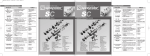
Manuale uso_VS02
13-04-2011
13:53
Pagina 1
FREQUENTLY ASKED QUESTIONS
PROBLEM
Paint settles in a larger
quantity on one of
the 2 sides
Irregular form
of the range
CAUSE
Paint comes out
intermittently.
REMEDY
1) One of the central holes of the head is
blocked with paint or is damaged.
2) Some paint is stuck on a lining
inside the nozzle.
3) The nozzle hole is damaged.
1) Clean or replace it.
2) Remove the nozzle and
clean thoroughly.
3) Replace it.
1)
2)
3)
4)
1) Increase the pulverization
pressure.
2) Reduce the paint pressure.
3) Thin it.
4) Replace it.
The pulverization pressure is low.
The paint output pressure is high.
The paint thickness is high.
The nozzle is damaged.
1) Insufficient air is flowing through the centre
of the head.
Paint settles to a greater 2) The pulverization pressure is high.
3) Some paint has blocked the passage of air
extent at the edges
between the head and the nozzle.
of the range
4) The head is not suitable for the nozzle
(different size).
Bow-shaped range
AUTOMATIC SPRAY GUNS
1) Increase it by adjusting
the nut.
2) Reduce it.
3) Clean the head and
the nozzle.
4) Replace it with a suitable
one.
1) One of the holes on the head nozzles
is blocked.
2) The nozzle hole is damaged.
1) Clean it.
2) Replace it.
1) The paint is not getting to the nozzle.
2) The passage of paint in the spray-gun is blocked.
3) The nozzle has not been placed properly
in its housing.
4) The nozzle housing in the spray-gun is damaged.
5) The gasket for the airtight sealing of the rod
is worn.
6) The paint is very thick.
1)
2)
3)
4)
5)
6)
1) The input pressure of the paint
is high.
Paint settles to a greater 2) The range breadth regulator
extent at the centre
is damaged.
Check the pump delivery.
Clean it.
Screw it.
Replace it.
Replace it.
Thin it.
Leaking of paint
from the nozzle.
The pulverization air
does not stop.
The pulverization air
does not come out.
1) The seal of the rod is worn.
2) The adjustment nut of the seal is slackened.
1)
2)
3)
4)
since 1968 , a family tradition
VS 02
USE AND MAINTENANCE MANUAL
AUTOMATIC SPRAY GUNS
spraycolor
DOMANDE FREQUENTI
®
PROBLEMA
since 1968 , a family tradition
VS 02
La vernice si deposita
in quantità maggiore
su uno dei 2 lati
Forma irregolare
del ventaglio
MANUALE D’USO E MANUTENZIONE
La vernice si deposita
maggiormente
ai lati del ventaglio
Forma del ventaglio
ad arco
La vernice esce
ad intermittenza.
1) Reduce it.
2) Replace it.
La vernice si deposita
maggiormente al centro
del ventaglio.
of the range.
Paint is coming out of
the drain hole.
spraycolor
®
1) Replace it.
2) Screw it.
The cone of the rod or the nozzle is damaged.
1) Replace the rod and nozzle.
The rod does not slide well inside the spray-gun. 2) Oil the sliding parts.
Dry paint is blocking the seal rod.
3) Replace the seal
The recoil spring of the rod is broken or released.
and clean its housing.
4) Replace it.
1) The recoil spring of the piston is broken
or released.
2) The airtight sealing gasket at the end of
the piston is worn.
1) Replace it.
2) Replace it.
1) The sliding of the rod is blocked.
2) The pressure gasket of the piston
is worn.
3) The opening pressure of the piston
is too low.
1) Clean it or oil it.
2) Replace it.
3) Increase it.
Esce vernice dal foro
di scarico.
Perdita di vernice
dall’ugello.
CAUSA
RIMEDIO
1) Uno dei fori centrali della testina è otturato
dalla vernice o danneggiato.
2) Della vernice si è bloccata su una parete
all’interno dell’ugello.
3) Il foro dell’ugello è danneggiato.
1) Pulire o sostituire.
2) Togliere l’ugello e pulire
accuratamente.
3) Sostituire.
1) La pressione di polverizzazione è bassa.
2) La pressione di uscita della vernice
è elevata.
3) La densità della vernice è elevata.
4) L’ugello è danneggiato.
1) Aumentare la pressione
di polverizzazione.
2) Diminuire la pressione
della vernice.
3) Diluire.
4) Sostituire.
1) L’aria che attraversa il centro della testina
è insufficiente.
2) La pressione di polverizzazione è elevata.
3) Della vernice ha otturato il passaggio aria
tra la testina e l’ugello.
4) La testina non è adatta all’ugello (misura diversa).
1) Aumentare registrando
con la ghiera.
2) Diminuire.
3) Pulire la testina e l’ugello.
4) Sostituirla con una idonea.
1) Uno dei fori sui beccucci della testina
è otturato.
2) Il foro dell’ugello è danneggiato.
1) Pulire.
2) Sostituire.
1)
2)
3)
4)
5)
Non arriva la vernice all’ugello.
Il passaggio di vernice nella pistola è otturato.
L’ugello non è arrivato bene nella sede.
La sede dell’ugello sulla pistola è danneggiata.
La guarnizione di tenuta dell’astina
è consumata.
6) La vernice è molto densa.
1) Controllare la mandata
della pompa.
2) Pulire.
3) Avvitare.
4) Sostituire.
5) Sostituire.
6) Diluire.
1) La pressione di arrivo della vernice
è elevata.
2) Il regolatore della larghezza del ventaglio
è danneggiato.
1) Diminuire.
2) Sostituire.
1) Il premistoppa dell’astina è consumato.
1) Sostituire.
2) La ghiera di registro del premistoppa è allentata. 2) Avvitare.
1) Il cono dell’astina o dell’ugello è danneggiato.
2) L’astina non scorre bene all’interno
della pistola.
3) Vernice secca blocca l’astina del premistoppa.
4) La molla di ritorno dell’astina è rotta o scarica.
L’area di polverizzazione 1) La molla di ritorno del pistone è rotta o scarica.
non si arresta.
2) La guarnizione di tenuta alla fine del pistone
1) Sostituire astina e ugello.
2) Oliare le parti di scorrimento.
3) Sostituire il premistoppa
e pulirne la sede.
4) Sostituire.
1) Sostituire.
2) Sostituire.
è usurata.
L’area di polverizzazione 1) L’astina è bloccata nello scorrimento.
2) La guarnizione di pressione del pistone
non esce.
è consumata
3) La pressione di apertura del pistone
è insufficiente.
1) Pulire o oliare.
2) Sostituire.
3) Aumentare.
Manuale uso_VS02
13-04-2011
1 - CONTENUTO
1 - CONTENTS
13:53
Pagina 2
spraycolor® ringrazia per aver scelto i nostri prodotti.
Nella confezione è presente la pistola automatica per verniciatura
mod. VS02 con il certificato di collaudo e garanzia.
Thank you for choosing spraycolor® products. The model VS02
paint automatic spray-gun is contained in the pack with his certificate
of testing and warrantee.
A
The connection tubes must have the following recommended diameters:
1 – paint intake point minimum 8x10 mm
2 – pilot air ( control opening ) minimum section 6x8 mm
3 – atomization air minimum section 8x10 mm
IMPORTANT check that the insides of the tubes are free of impurities
and residues.
7 - PRIMO AVVIAMENTO IN MACCHINA
7 - INITIAL START-UP IN MACHINE
E
5 - PRESSIONI DI UTILIZZO
5 - USE PRESSURES
2 - AVVERTENZE
2 - INSTRUCTIONS
Si raccomanda lo smaltimento dell’imballo e di evitare
la dispersione nell’ambiente seguendo le normative locali.
You are advised to dispose of the packaging in accordance
with the local regulations and to avoid littering the environment.
3 - SICUREZZA
3 - SAFETY
4 - INSTALLAZIONE
4 - INSTALLATION
Effettuare le operazioni di installazione pistola a macchinario spento.
Carry out the spray-gun installation operations with the machinery switched off.
La distanza consigliata fra il tappeto e la testina è compresa
tra 150÷180 mm (fig. A). La pistola è provvista di ingressi da 1/4” gas (fig.B).
Le tubazioni di connessione dovranno essere dei seguenti diametri consigliati:
1 - ingresso vernice minimo mm 8x10
2 - aria pilota ( apertura di comando) sezione minima mm 6x8
3 - aria di atomizzazione sezione minima mm 8x10
IMPORTANTE verificare l’assenza di impurità o residui all’interno
delle tubazioni.
The recommended distance between the belt and the head is 150-180 mm
(fig. A). The spray-gun is provided with 1/4” gas intake points (fig. B).
Aria pilota (apertura di comando)
Aria polverizzazione
Ingresso vernice pompa
CONSIGLIATA 3.0 bar (max 3.5 bar)
CONSIGLIATA 1.8 ÷ 2.5 bar
variabile in funzione della densità
Pilot air (control opening)
Pulverization air
Paint pump intake point
RECOMMENDED 3.0 bar (max 3.5 bar)
RECOMMENDED 1.8 - 2.5 bar
variable depending on thickness
6 - DIAMETRI DISPONIBILI DI KIT: ASTINA TESTINA UGELLO
6 - DIAMETERS AVAILABLE FOR ROD-HEAD-NOZZLE KITS
La pistola è fornita completa di kit astina-testina-ugello nella misura
desiderata, sono disponibili di serie i seguenti diametri:
Ø 0.8 per piccole quantità di vernici a media densità
Ø 1.0 per medie quantità di vernici a media densità
Ø 1.2 per medie quantita di vernici a alta densità
Ø 1.5 per grandi quantità di vernici a alta densità
The spray-gun is supplied with a needle-head-nozzle kit in the desired
size; the following diameters are available mass-produced:
Ø 0.8 for small quantities of medium thickness paint
Ø 1.0 for medium quantities of medium thickness paint
Ø 1.2 for medium quantities of high thickness paint
Ø 1.5 for large quantities of high thickness paint
Dopo avere installato la
pistola nella cabina di
verniciatura e avere
regolato le pressioni
come consigliato al
paragrafo 5 procedere
alla regolazione in funzione all’utilizzo richiesto
- regolare la quantità
desiderata di vernice
con il volantino (fig. C)
posteriore alla pistola.
La regolazione del ventaglio di atomizzazione è possibile con i due
volantini numerati sulla pistola. Il volantino a destra regola l’ampiezza
del ventaglio sulla testina (fig. D). Il volantino a sinistra regola il flusso di aria al centro della testina (fig. E).
C
B
G
D
After you have installed the spray-gun in the spray booth and regulated
the pressures as advised in paragraph 5, proceed with the adjustment
according to the required use
- regulate the desired quantity of paint with the back adjustment wheel
(fig. C) on the spray-gun.
Regulation of the range of atomization is possible with the two side
adjustment wheels of the spray-gun. The right adjustment wheel
regulates the width of the range on the head (fig. D). The left
adjustment wheel regulates the airflow at the centre of the head (fig. E).
H
I
L
8 - MANUTENZIONE ORDINARIA
8 - ROUTINE MAINTENANCE
F
La pulizia della pistola è indispensabile per un buon funzionamento
della stessa.
Per la pulizia esterna del corpo pistola non usare mai detergenti
corrosivi o abrasivi (fig. F), quando possibile evitare l’utilizzo
di macchine ad alta pressione,così facendo si manterranno sempre
visibili e di facile lettura i riferimenti indispensabili alle regolazioni.
- Ad ogni fermo macchina svuotare la vernice presente nella pistola
e spruzzare con acqua pulita o altro detergente per non meno
di 15 minuti.
Quando si smonta il kit astina testina ugello procedere come segue:
M
N
- allentare e togliere il volantino vernice (fig. G)
- rimuovere il contenitore molla (pz.4) e la molla astina (pz.14) (fig.H)
- con l’aiuto di una pinza estrarre l’astina (fig. I)
- svitare la ghiera (fig. L).
- togliere la testina e soffiare nei fori con aria compressa dall’esterno
verso l’interno (fig. M).
- allentare e togliere l’ugello utilizzando una chiave esagonale da 13
mm (fig. N).
- svitare la ghiera (pz 20) per estrarre la guarnizione (pz 18) (fig O).
PER RIMONTARE IL TUTTO PROCEDERE IN SENSO INVERSO.
IMPORTANTE Osservare il corretto verso di inserimento della guarnizione (fig P); l’ugello deve essere sempre montato prima dell’astina.
It is essential to clean the spray-gun in order that it will operates
properly.
To clean the outside of the spray-gun body never use corrosive
or abrasive detergents (fig. F) and whenever possible avoid using
high pressure machines. In this way the indispensable references
for regulation will always remain visible and easy to read.
- At every machine shutdown, empty the spray-gun of any paint that
is present and spray it with clean water or another detergent for at
least 15 minutes.
Proceed as follows when you dismantle the rod-head-nozzle kit:
- slacken and remove the paint adjustment wheel (fig. G)
- remove the spring container (4) and the needle spring (14) (fig. H)
- use pliers to remove the needle (fig. I)
- unscrew the nut for head (fig. L).
- remove the head and blow compressed air into the holes from
the outside towards the inside (fig. M).
- slacken and remove the nozzle using a 13mm hexagonal spanner
(fig. N).
- unscrew the cap gasket (20) to remove the packing gasket (18)
(fig. O)
PROCEED IN REVERSE ORDER TO REASSEMBLE EVERYTHING.
IMPORTANT The nozzle
must always be assembled
O
before the needle.
Observe the proper order of
insertion of the seal (fig.P).
P
www.spraycolor.com
Assistenza Clienti /
Customer Service:
[email protected]