1
GB
F
D
ISTRUZIONI DI MONTAGGIO
ASSEMBLING INSTRUCTIONS
ISTRUTIONS D’ ASSEMBLAGE
MONTAGEANLEITUNGEN
SAIMA
I
I
GB
F
D
MECCANICA S.P.A.
I
SAIMA
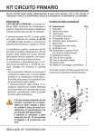
INTRODUZIONE
CONTENUTO: nel presente manuale, vengono riportate le disposizioni e le modalità di installazione e del montaggio delle cabine di
verniciatura prodotte dalla SAlMA Meccanica S.p.A., Località Indicatore 60/G, AREZZO, ITALIA.
DISPOSIZIONI GENERALI: é obbligatorio, secondo le normative CE, ma è comunque consigliato anche nei paesi extracomunitari, che gli
impianti vengano assemblati ed installati da personale espressamente qualificato dal costruttore o chi da esso abbia conseguito questa
facoltà espressamente.
AVVERTENZE
E’ importante, prima di iniziare le operazioni di assemblaggio, attenersi a quanto sotto riportato:
1. Scaricare e conservare i componenti dell’impianto in un’area, esterna a quella di assemblaggio, che garantisca il mantenimento
delle loro caratteristiche originarie; in caso di deposito in area esterna, coprire tutti i componenti con teli impermeabili di
protezione (Vedi Libretto di uso e manutenzione)
2. Verificare, tramite Lista di riscontro, che tutti i componenti previsti siano presenti; in caso contrario contattare immediatamente la
SAIMA MECCANICA
3. Verificare, tramite layout, che le caratteristiche dell’edificio siano idonei ad ospitare l’impianto; in caso contrario contattare
immediatamente la SAIMA MECCANICA
4. Disimballare tutti i componenti e smaltire le protezioni secondo le leggi esistenti
5. Verificare che i componenti non abbiano subito danni o comunque siano idonei ad essere utilizzati; in caso contrario contattare
immediatamente la SAIMA MECCANICA
6. Verificare o richiedere la presenza dei mezzi di movimentazione e sollevamento necessari
7. Attrezzature consigliate per le operazioni d’assemblaggio, in numero variabile:
avvitatrice a batteria;
trapano a batteria;
Mola per taglio e smerigliatura
Roditrice
Applicamastice
Cacciaviti, chiavi e utensili vari
Scala di almeno 3 m
ALLEGATI: sono allegati al presente tutti i manuali del costruttore dei vari dispositivi o attuatori, che la SAlMA Meccanica S.p.A. fornisce
con la cabina di verniciatura stessa, ma che essa non produce, quali bruciatori, lift, sollevatori o archi a raggi infrarossi, ecc
BRUCIATORE: il bruciatore eventualmente fornito con la cabina di verniciatura, deve essere tarato e collaudato da personale qualificato
dal costruttore del bruciatore medesimo. La SAlMA Meccanica S.p.A monta sulle proprie cabine solo bruciatori, siano a gasolio, metano o
GPL, di ditte che abbiano una rete di vendita ed assistenza presente nel paese di destinazione della cabina di verniciatura stessa.
ATTENZIONE!
E’ espressamente vietata ogni riproduzione, anche parziale, del presente manuale e di ogni suo allegato, senza autorizzazione scritta della
SAlMA Meccanica S.P.A..
GB
INTRODUCTION
ENCLOSURES: to the present are attached all the manuals from the constructors of the devices and actuators which SAlMA Meccanica
S.p.A. deliver with the booth, but do not produce, like burners, lifts, infra red archs, etc.
BURNER: the burner eventually delivered with the spray booth, must be set and tested by qualified personal from the burners constructor.
SAlMA Meccanica S.p.A deliver for his own booths only diesel oil or gas burners from companies which have a sell and assistance net in
the final assembling country.
ATTENTION!
It’s expressly forbidden to reproduce, also in parts the present manual and any of his enclosures without written authorization from SAlMA
Meccanica S.P.A.
SAIMA
CONTENT: the present handbook explains the instructions and the installation and assembling methods for the spray booth produced by
SAlMA Meccanica S.p.A., Località Indicatore 60/G, AREZZO, ITALIA.
GENERAL INSTRUCTIONS: it is obligatory, according to the CE rules, but anyway recommended also in the extra European Community
countries that the plants will be assembled and installed through particularly qualified personnel by the constructor or by whom got
expressly the qualification.
REMARKS
It’s important to follow the here mentioned indications before starting the assembling:
1. Unload and keep the plant components in a to the assemble place external area, which guarantees the maintenance of the
original characteristics; in case of outside recovering, cover all components with waterproof material (See Use and maintenance
Handbook).
2. Verify if all foreseen components are present; if not, contact immediately SAIMA MECCANICA.
3. Verify, through the layout, if the building is suitable to house the plant; if not, contact immediately SAIMA MECCANICA.
4. Unpack all the components and dispose off the protection material following the local regulations.
5. Verify the entireness of the components or if they are suitable to be used; if not, contact immediately SAIMA MECCANICA.
6. Verify the presence or ask for the necessary handling and hoisting equipments.
Suggested tooling for the assembling, in variable quantity:
Cordless screwer
Cordless drill
Grinding wheel
Nibbling machine
Putty applier
Screwdrivers, keys and various tools
Minimum 3 m long ladder
2
MECCANICA S.P.A.
F
SAIMA
INTRODUCTION
CONTENU: ce manuel contient les dispositions et les modalités d’installation et d’assemblage des cabines de peinture produites par
SAlMA Meccanica S.p.A., Località Indicatore 60/G, AREZZO, ITALIA.
DISPOSITIONS GENERALES: il est obligatoire, selon les lois CE, mais il est conseillé aussi dans les pays extra communautaires, que les
installations soient assemblées et installées par personnel expressément qualifié par le constructeur ou par celui qui a obtenu cette faculté.
AVERTISSEMENTS
Il est important, avant de commencer les opérations d’assemblage, suivre ce qu’il suit:
1. Déchargez et conservez les composants de l’installations dans une zone extérieure à celle d’assemblage, et qui puisse
conserver leurs caractéristiques originaires; en cas de dépôt dans une zone extérieure, couvrez tous les composants avec des
toiles imperméables de protection (Voir le manuel d’usage et entretien);
2. Vérifiez s’il y a tous les composants prévus; dans le cas contraire, contactez immédiatement SAIMA MECCANICA
3. Vérifiez, par le lay-out, que toutes les caractéristiques du bâtiment soient appropriées pour abriter l’installation; dans le cas
contraire, contactez immédiatement SAIMA MECCANICA
4. Désemballez tous les composants et éliminez les protections selon les lois en vigueur;
5. Vérifiez que les composants ne soient pas endommagés ou qu’ils puissent être utilisés; dans le cas contraire, contactez
immédiatement SAIMA MECCANICA;
6. Vérifiez ou demandez la présence des moyens nécessaires pour mouvementer et soulever;
7. Outillages conseillés pour les opérations d’assemblages, en quantité variable:
Visseuse à batterie;
Perceuse à batterie;
Meule émeri et coupe
Grignoteuse
Applicateur de mastic
Tournevis, clés et outillages variés
Escalier d’au moins 3 m
PIECES ANNEXES: dans les pièces annexes vous trouverez tous les manuels du constructeur des différents dispositifs ou actionneurs
que SAlMA Meccanica S.p.A. fournit avec la cabine de peinture même, mais que elle ne produise pas, c'est-à-dire brûleurs, lift, élévateurs
ou arches à rayons infrarouges, etc.
BRULEUR: le brûleur éventuellement fourni avec la cabine de peinture, doit être taré et essayé par personnel qui a été qualifié par le
constructeur du brûleur même. SAlMA Meccanica S.p.A assemble sur ses propres cabines seulement brûleurs, à gazole, méthane ou
GPL, de firmes qui aient un réseau de vente et assistance présent dans les pays de destination de la cabine de peinture.
ATTENTION!
Il est interdit de reproduire, même si partiellement, ce manuel et chaque pièce annexe sans l’autorisation écrite de SAlMA Meccanica
S.P.A.
EINFÜHRUNG
INHALT: In diesem Handbuch werden die Richtlinien und die Aufbau und Installationsangaben für die Lackierkabinen der SAlMA
Meccanica S.p.A., Località Indicatore 60/G, AREZZO, ITALIA angegeben.
ALLGEMEINE BESTIMMUNGEN: den CE Normen nach, ist es Vorschrift und in den außereuropäischen Ländern angebracht, die
Anlagen durch von dem Produzenten extra geschultem Personal oder durch Technikern welche die Vollmacht erreicht haben, zu
installieren.
BEMERKUNGEN
Vor dem Beginn der Montage ist es wichtig folgende Punkte zu berücksichtigen:
1. Die gesendeten Teile abladen und in einer dem Aufbau externem Platz, in dem die ursprünglichen Eigenschaften erhalten
bleiben, aufbewahren; falls das Material draußen gelagert wird, mit Wetterfestenplan abdecken (Siehe Handbuch für Gebrauch
und Wartung).
2. Prüfen ob alle vorgesehenen Teile vorhanden sind; falls nicht, sofort mit der SAIMA MECCANICA in Kontakt treten.
3. Dem Lay-out nach prüfen ob das Gebäude in dem die Kabine aufgebaut werden soll angebracht ist; falls nicht, sofort mit der
SAIMA MECCANICA in Kontakt treten.
4. Das Material auspacken und das Verpackungsmaterial den Landesrichtlinien gemäß entsorgen.
5. Prüfen ob das Material in perfektem Zustand oder für den Aufbau tauglich sei; falls nicht, sofort mit der SAIMA MECCANICA in
Kontakt treten.
6. Die Anwesenheit der nötigen Hebe und Bewegungsvorrichtungen überprüfen oder beanstanden.
7. Empfohlene Ausrüstung für den Aufbau, in unterschiedlicher Menge:
Akku - Schrauber
Akku - Bohrmaschine
Schleifscheibe für Schnitt und Schliff
Knabbermaschine
Kittaufträger
Schraubenzieher, Schlüssel und weiteres Werkzeug
Leiter mindestens 3 m lang
BEILIEGEND: diesem liegen alle Handbücher der Hersteller der verschiedenen Vorrichtungen und Aktuatoren die SAlMA Meccanica
S.p.A. mir der Kabine liefert aber welche sie nicht selbst herstellt, so wie Brenner, Paint-Lift, Hebebühnen, Infrarottrockner, usw.
BRENNER: der eventuell mit der Lackierkabine gelieferte Brenner, muß von einem Techniker des Brennerherstellers eingestellt und
geprüft werden. Die SAlMA Meccanica S.p.A installiert in Ihren Kabinen Öl oder Gasbrenner von Erzeugern die ein Verkauf und
Wartungsnetz haben im Lande in dem die Kabine aufgebaut wird.
ACHTUNG!
Jegliche Reproduktion dieses Handbuches und der Beilagen ist ausdrücklich Verboten ohne schriftliche Genehmigung der SAlMA
Meccanica S.P.A.
SAIMA
D
3
SAIMA
GB
F
D
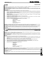
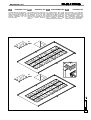
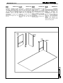
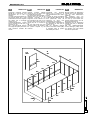
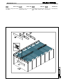
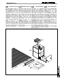
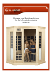
BASAMENTO ED1
BASEMENT ED1
SOUBASSEMENT ED1
UNTERBAU ED1
La
cabine
della
SAlMA
Meccanica S.p.A., deve essere
provvista di un’opera adeguata
per il deflusso ed eventuale
successivo trattamento dell’aria
usata dalla cabina di verniciatura
durante il suo funzionamento
normale. Tipicamente il cliente
provvede ad eseguire le opere
murarie, su nostro disegno,
quindi il tecnico preposto al
montaggio si troverà ad operare
in un ambiente simile a quello
rappresentato. Nel caso il tecnico
si trovi in un ambiente senza
opere murarie o con uno scasso
nel pavimento di massimo 40
cm, la cabina di verniciatura é
certamente provvista di basamento metallico prefabbricato,
per il cui montaggio il tecnico
dovrà fare riferimento alla
sezione dedicata al basamento
metallico del presente libretto.
The spray booth from SAlMA
Meccanica S.p.A. must be
supplied with an adequate
basement for the air outflow and
probable subsequent processing
of the used air in the spray booth
during
a
normal
running.
Normally the customer provides
for masonry works according to
our drawings and so the
assembler will be in front of an
environment similar to our
drawing. If the assembler will be
in a place without masonry works
or find a max. 40 cm high digged
hole, the spray booth will have a
prefabricated metal basement to
be assembled according to the
indications given in this manual.
La cabine de SAlMA Meccanica
S.p.A. doit être fournie d’un
adéquat travail pour l’écoulement
et l’éventuel successif traitement
de l’air utilisé par la cabine de
peinture
pendant
son
fonctionnement
ordinaire.
Généralement le client réalise les
travaux de maçonnerie sur notre
dessin, donc le technicien
préposé à l’assemblage opérera
dans un milieu semblable à celui
ici représenté. Si le technicien se
trouvera dans un milieu sans
travaux de maçonnerie ou avec
un
encaissement
dans
le
plancher de max 40 cm, la
cabine de peinture est sûrement
fournie
d’un
soubassement
métallique préfabriqué, pour son
assemblage il faut que le
technicien se réfère à la section
dédiée
au
soubassement
métallique de ce manuel.
Die Kabine von der SAlMA
Meccanica S.p.A., hat einen
angebrachten Unterbau für die
Luftabführung und für die
eventuelle
Aufbereitung
der
Kabinenluft
während
eines
normalen Gebrauches nötig.
Normalerweise
mauert
der
Kunde nach unseren Angaben,
und demnach findet der Monteur
einen der Zeichnung ähnlichem
Bau. Wenn der Monteur keine
Bauten oder eine Aushebung
von höchstens 40 cm vorfindet,
wird die Kabine ganz sicher
einen vorfertigen Metallunterbau
haben, und er wird sich dann an
die Richtlinien über
Metallunterbaue
dieses
Anleitungshandbuches halten.
SAIMA
MECCANICA S.P.A.
4
SAIMA
MECCANICA S.P.A.
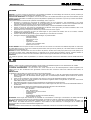
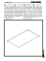
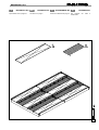
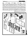
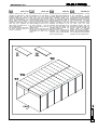
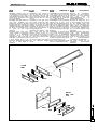
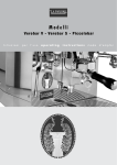
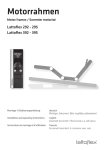
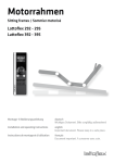
BASAMENTO ED2
Si proceda all’inserimento dei
telai portafiltri (G) e/o delle
vasche centrali (F) appoggiandoli
ai profili ad “L” di contorno alle
fosse.
GB
BASEMENT ED2
Insert the filter holding frames
(G) and/or the central basins (F)
leaning them against to the “L”
section bars around the pits.
F
SOUBASSEMENT ED2
Insérez les châssis porte-filtres
(G) et/ou les cuves centrales (F)
en les appuyant aux profils en “L”
de contour aux fosses.
D
UNTERBAU ED2
Die
Filterhalterrahmen
(G)
und/oder die zentralen Tanks (F)
einfügen in dem sie an die „L“
Profile rund um die Gruben
gelehnt werden.
G
x15
F
x2
G
x12
SAIMA
I
5
SAIMA
I
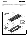
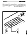
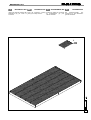
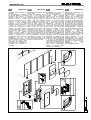
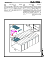
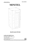
BASAMENTO ED3
Le griglie di protezione delle
fosse (H), devono essere
posizionate con la parte più
stretta portante parallela all’inizio
delle fosse e dei telai sottogriglia.
A fine montaggio andranno
rimosse per l’inserimento del
filtro Paint - stop (P) Vedi pag. 9.
GB
BASEMENT ED3
The pits protection grids (H),
must be positioned with the
shortest supporting part parallel
to the beginning of the pits and
filter holder frames. At the end of
the assembling they will be
removed in matter to insert the
Paint-stop filters (P) See page 9.
F
SOUBASSEMENT ED3
Les grilles de protection des
fosses
(H)
doivent
être
positionnées avec la partie la
plus étroite portante parallèle au
commencement des fosses et
des châssis sous-grille. A la fin
de l’assemblage, il faut les
enlever pour insérer le filtre Paint
- stop (P). Voir page 9.
D
UNTERBAU ED3
Die Grubenabdeckungsgitter (H),
müssen mit dem tragenden
schmalerem Teil parallel zu dem
Beginn der Gruben und der
Untergitterrahmen
angeordnet
werden.
Nach
beendetem
Aufbau der Kabine werden sie
entfernt um die Paint-stop Filter
(P) einzubauen. Siehe Seite 9.
H
x18
SAIMA
MECCANICA S.P.A.
6
SAIMA
MECCANICA S.P.A.
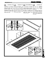
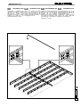
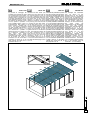
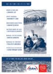
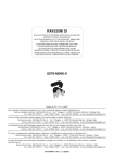
BASAMENTO ED4
Posizionare le “U” di base in
dotazione (U2 + U1) secondo gli
schemi sotto riportati in maniera
equidistante dalle fosse. Il
successivo fissaggio con viti ad
espansione avverrà a struttura
completamente montata dopo
misurazione delle diagonali della
cabina che devono essere
perfettamente uguali.
GB
BASEMENT ED4
Position the delivered
“U”
section bars (U2 + U1) as shown
on the plan at equal distance
from the pits. The subsequent
fixing with expansion bolts must
occur only after the complete
assembling of the structure and
after the measuring of the
diagonals of the booth, which
must be perfectly identical.
F
SOUBASSEMENT ED4
Positionnez les “U” de base (U2
+ U1) fournis en position
équidistante des fosses selon les
schémas indiqués au-dessous.
Le successif fixage avec des vis
d’expansion sera exécuté une
fois que la structure sera
complètement montée après le
mesurage des diagonales de la
cabine
qui
doivent
être
parfaitement égales.
D
UNTERBAU ED4
Die
in
der
Ausstattung
vorhandenen “U” Basisprofile
(U2 + U1) der graphischen
Darstellung nach in gleichem
Abstand
von
den
Gruben
positionieren.
Die darauffolgende Befestigung
mit Expansionsschrauben wird
erst bei komplett aufgebauter
Struktur erfolgen und nach der
Abmessung der Diagonalen der
Kabine, welche vollkommen egal
sein müssen.
U1
x4
U2
x1
U2
U1
U1
SAIMA
I
7
SAIMA
MECCANICA S.P.A.
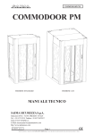
BASAMENTO ED5
Il posizionamento dei filtri Paintstop (P) nei telai portafiltri (G)
dopo il taglio a misura dal rotolo
fornito in dotazione, avverrà ad
impianto completato per ovvi
motivi di pulizia.
GB
BASEMENT ED5
The positioning of the paint-stop
filter (P) cut in the right size from
the delivered roll in the filter
holder frames (G) will be done
only after the assembling of the
booth for obvious cleanness
reasons.
F
SOUBASSEMENT ED5
Le positionnement des filtres
Paint-stop (P) dans les châssis
porte-filtres (G) après la coupe à
mesure du rouleau fourni sera
exécuté une fois que l’installation
sera
complétée
pour
des
évidentes raisons de propreté.
D
UNTERBAU ED5
Das Einsetzen der Paint-stop
Filter (P) in die Filterrahmen (G),
nach dem Schnitt nach Maß von
der beiliegenden Rolle, soll
wegen Verunreinigungsprobleme
erst nach dem vollständigen
Aufbau der Kabine geschehen.
P
x15
P
x12
SAIMA
I
8
SAIMA
I
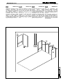
BASAMENTO MT1
La
cabina
della
SAlMA
Meccanica S.p.A., deve essere
provvista di un’opera adeguata
per il deflusso ed eventuale
successivo trattamento dell’aria
usata dalla cabina di verniciatura
durante il suo funzionamento
normale. Nel caso il tecnico si
trovi in un ambiente con uno
scasso nel pavimento di max 40
cm, la cabina di verniciatura é
certamente provvista di basamento metallico prefabbricato,
quindi il tecnico preposto al
montaggio si troverà ad operare
in un ambiente simile a quello
rappresentato. Se il cliente ha
provveduto ad eseguire le opere
murarie, su nostro disegno, per il
montaggio, il tecnico dovrà fare
riferimento alla sezione dedicata
al basamento realizzato sul
posto del presente libretto.
GB
BASEMENT MT1
The spray booth from SAlMA
Meccanica S.p.A., needs to be
provided with adequate masonry
works for the outflow and
eventually for the successive
treatment of the used air during
his normal running. If the
assembler will be in front of a
hole maximum 40 cm deep, the
booth certainly is provided with a
prefabricated metallic basement
and therefore he will operate in a
surrounding like the represented
here under. If the customer has
done the concrete works as in
our drawings, the assembler will
follow the assembling indications
in this booklet regarding the
masonry basements.
F
SOUBASSEMENT MT1
La cabine de SAlMA Meccanica
S.p.A., doit être fournie d’un
travail adéquat pour l’écoulement
et l’éventuel successif traitement
de l’air utilisé par la cabine de
peinture
pendant
son
fonctionnement ordinaire. Si le
technicien se trouve dans un
milieu avec un encaissement
dans le plancher de max 40 cm,
la cabine de peinture est
sûrement
fournie
d’un
soubassement
métallique
préfabriqué, donc le technicien
préposé à l’assemblage opérera
dans un milieu semblable à celui
ici représenté. Si le client a
exécuté
les
travaux
de
maçonnerie sur notre dessin,
pour l’assemblage il faut que le
technicien se réfère à la section
de ce manuel dédiée au
soubassement réalisé sur place.
D
UNTERBAU MT1
Die Lackierkabinen von der
SAlMA
Meccanica
S.p.A.,
benötigen einen angemessenen
Unterbau für die Luftabscheidung
und für die eventuelle Säuberung
der verbrauchten Luft während
dem normalen Gebrauch der
Kabine. Wenn der Monteur eine
höchstens 40 cm hohe Grube
vorfindet, ist die Kabine sicher
mit
einem
vorfertigem
Metallunterbau ausgestattet und
so wird er einem dem hier
beschriebenen ähnlichem Milieu
tätig sein. Falls der Kunde
unseren Angaben nach Gruben
gebaut hat, muß der Monteur
sich an die Richtlinien für
gemauerte Unterbaue dieses
Büchleins halten.
SAIMA
MECCANICA S.P.A.
9
SAIMA
MECCANICA S.P.A.
I
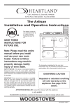
BASAMENTO MT2
Accoppiare a 2 a 2 i fascioni
laterali (A) e centrali (B),
utilizzando i bulloni da 8 x 40 in
dotazione stringendo 1 solo
dado. Il secondo dado servirà
per il fissaggio della traversa
centrale (vedi pag. 14).
GB
BASEMENT MT2
Join together 2 by 2 the side (A)
and central (B) beams, using the
delivered bolts 8 x 40, tightening
only 1 stud nut. The second nut
will be used for the fixing of the
central crossbar (see page 14).
F
SOUBASSEMENT MT2
Accouplez 2 par 2 les bandeaux
latéraux (A) et centraux (B), en
utilisant les boulons de 8 x 40
fournis, en serrant 1 écru
seulement. Le deuxième écru
sera utilisé pour le fixage de la
traverse centrale (voir page 14).
D
UNTERBAU MT2
Die seitlichen (A) und mittleren
(B) Balken mit den gelieferten
Bolzen 8 x 40 paaren und dabei
nur 1 Mutter anziehen. Die
zweite Mutter wird für die
Befestigung
des
mittleren
Querbalkens benutzt werden.
(Siehe Seite 14). .
A
x4
A1
nr 2
B1
nr 4
SAIMA
B
x8
10
SAIMA
MECCANICA S.P.A.
BASAMENTO MT3
Posizionare, secondo Lay-out i 2
fascioni laterali già accoppiati e
fissare con bulloni 8 x 40 il
fascione posteriore (C) che ha
la stessa altezza. I fascioni
devono avere il profilo ad “H”
all’esterno.
GB
BASEMENT MT3
Position according to the Lay-out
the 2 coupled side beams and fix
the rear beam (C) with the same
height with bolts 8 x 40. The
beams must show the “H” profile
on the outside.
F
SOUBASSEMENT MT3
Positionnez, selon le Lay-out, les
2 bandeaux latéraux qui ont été
déjà accouplés et fixez, avec les
boulons 8 x 40, le bandeau
postérieur (C) qui a la même
hauteur. Les bandeaux doivent
avoir le profil en “H” à l’extérieur.
D
UNTERBAU MT3
Die gepaarten seitlichen Balken
dem Lay-out nach positionieren
und mit 8 x 40 Bolzen den
hinteren Balken(C), der die selbe
Höhe aufweist befestigen. Das
„H“ Profil muß an der Außenseite
bleiben.
A1
x1
C
x1
SAIMA
I
11
SAIMA
MECCANICA S.P.A.
BASAMENTO MT4
Fissare i fascioni centrali (B) al
fascione posteriore (C) con i
bulloni da 8 x 40 in dotazione.
Tutti i fascioni sono dotati di
inserti e viti per il livellamento
(max 20/30 mm) del basamento,
operazione da fare a basamento
assemblato.
GB
BASAMENTO MT4
Fix the central beams (B) to the
rear beam (C) with the delivered
bolts 8 x 40. All the beams have
basement levelling inserts and
screws (max 20/30 mm). The
levelling must be done after the
complete assembling of the
basement.
F
SOUBASSEMENT MT4
Fixez les bandeaux centraux (B)
au bandeau postérieur (C) avec
les boulons de 8 x 40 fournis.
Tous les bandeaux sont fournis
des parties intercalaires et des
vis pour le nivelage (max 20/30
mm)
du
soubassement,
opération à exécuter une fois
que le soubassement a été
assemblé.
D
BASAMENTO MT4
Die zentralen Balken (B) an den
hinteren Balken (C) mit den 8 x
40 gelieferten Bolzen befestigen.
Alle Balken haben Einfügungen
und Schrauben (max 20/30 mm)
zur Nivellierung des Unterbaus.
Die Nivellierung darf erst nach
komplettem
Aufbau
des
Unterbaus erfolgen.
B1
x4
SAIMA
I
12
SAIMA
MECCANICA S.P.A.
BASAMENTO MT5
Aggiungere i 2 distanziali (D),
fissandoli sia ai fascioni centrali
(B) che ai fascioni laterali
centralmente
rispetto
alla
lunghezza, seguendo le forature
esistenti, con i bulloni 8 x 40
presenti utilizzando il 2° dado.
GB
BASAMENTO MT5
Add the 2 spacers (D), fixing
them to the central beams (B)
and to the side beams in the
middle of the length following the
existing holes with the bolts 8 x
40 using the 2nd nut.
F
SOUBASSEMENT MT5
Ajoutez, en suivant les perçages
existants, les 2 écarteurs D et
fixez-les soit aux bandeaux
centraux soit aux bandeaux
latéraux (B) en position centrale
par rapport à la longueur, avec
les boulons 8 x 40 présents en
utilisant le 2ème écrou.
D
BASAMENTO MT5
Die 2 Distanzstücke (D), an die
zentralen Balken (B) und an die
seitlichen Balken im Zentrum der
Länge befestigen, die
vorhandenen
Durchbohrungen
folgend, die zweite Nutte der
Bolzen 8 x 40 benutzend.
D
x2
SAIMA
I
13
SAIMA
I
BASAMENTO MT6
Fissare i rimanenti fascioni
laterali (A) al fascione posteriore
(B) e a quello anteriore più basso
(E).
Stringendo tutti i bulloni, livellare
l’impianto
con
le
viti
di
regolazione (pag. 12) e mettere
perfettamente in squadra.
E
x1
GB
BASEMENT MT6
Fix the remaining side beams (A)
to the rear beam (B) and to the
lower front beam (E).
Tighten all the bolts, level the
basement with the setting screws
(page 12) and bring it at right
angles.
F
SOUBASSEMENT MT6
Fixez les restants bandeaux
latéraux
(A)
au
bandeau
postérieur (B) et à celui antérieur
le plus bas (E).
En serrant tous les boulons,
nivelez l’installation avec les vis
de réglage (page 12) et mettez
parfaitement en équerre.
D
UNTERBAU MT6
Die restlichen Seitenbalken (A)
an den hinteren Balken (B) und
an den vorderen niedrigeren
Balken (E) befestigen.
Alle Bolzen anziehen, den
Unterbau mit den Schrauben
nivellieren (Seite 12) und perfekt
Winkeln.
A1
x1
SAIMA
MECCANICA S.P.A.
14
SAIMA
I
BASAMENTO MT7
Riprocedere come a pagina 6.
GB
BASEMENT MT7
Proceed as on page 6.
F
SOUBASSEMENT MT7
D
UNTERBAU MT7
Suivez les indications de page 6. Die Angaben
wiederholen.
F
x6
der
Seite
6
G
x8
SAIMA
MECCANICA S.P.A.
15
SAIMA
I
BASAMENTO MT8
I filtri Paint-stop (P) del
basamento, forniti in rotoli da 20
m, devono essere tagliati a
misura e inseriti nel basamento
ad impianto completato.
GB
BASEMENT MT8
The
Paint-stop
filters
(P)
delivered in 20 m rolls, must be
cut to measure and inserted in
the basement at complete
assembled plant.
F
SOUBASSEMENT MT8
Les filtres Paint-stop (P) du
soubassement, qui sont fournis
en rouleaux de 20 m, doivent
être coupés à mesure et insérés
dans le soubassement une fois
que l’installation a été complétée.
D
UNTERBAU MT8
Die Paint-stop Filter (P), welche
in 20m Rollen geliefert werden,
müssen nach Maß geschnitten
und bei fertiger Anlage in den
Unterbau eingesetzt werden.
H
x8
SAIMA
MECCANICA S.P.A.
16
SAIMA
MECCANICA S.P.A.
I
BASAMENTO MT9
GB
BASEMENT MT9
F
SOUBASSEMENT MT9
D
UNTERBAU MT9
Inserire le griglie di copertura del Insert the basement covering Insérez les grilles de couverture Die
Abdeckungsgitter
des
basamento (H) per motivi di grids (H) for safety reasons.
du soubassement (H) pour Unterbaus (H) aus Sicherheitssicurezza.
raisons de sûreté.
gründen einsetzen.
SAIMA
I
x35
17
SAIMA
MECCANICA S.P.A.
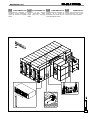
PARETI PG1
Scegliere il pannello di fondo
(PF) più
nel angolo sinistro,
un pannello laterale (PL) ed una
“C” d’angolo (C1), inserirli nelle
“U” di base ed accoppiarli
secondo la figura utilizzando
autoforanti 4,8 x 19 solo
esternamente in numero di 5/6
per pannello.
Attn.: Le “C” d’angolo sono 1 Dx
ed 1 Sn.
GB
WALLS PG1
Choose the
narrowest rear
panel (PF)
in the left corner,
one side panel (PL) and one
angle “C” (C1). Insert them in
the base “U” and couple them
together with the self-tapping
screws 4,8 x 19 only from
outside in a quantity of 5/6 for
each panel.
Attn.: The angle “C” for the right
side and the left side are
different.
PL
x1
F
PAROIS PG1
Choissez le panneau de fond
(PF) le plus étroit ,
dans
l’angle gauche, un panneau
latéral (PL) et un “C” d’angle
(C1); insérez-les dans les “U” de
base et accouplez-les selon la
figure en utilisant les vis autoperçantes 4,8 x 19 à l’extérieur
seulement au nombre de 5/6
pour panneau.
Attention: Les “C” d’angle sont 1
droit et 1 gauche.
D
WÄNDE PG1
Ein
schmaleres
Hinterwandpaneel (PF) Bohrung
in der linken oberen Ecke, ein
Seitenwand-Paneel (PL) und ein
Doppel “C” Eckprofil (C1)
vorbereiten.
In
die
„U“
Unterbauschienen einfügen und
dem Bild nach von außen, mit
den
selbstschneidenden
Schrauben 4,8 x 19 zusammen
setzen, mit 5/6 Schrauben pro
Paneel.
Achtung: Das Eckprofil der
rechten Ecke ist dem von der
linken Ecke nicht gleich.
PF1
x1
C1
PF1
PL
C1
x1
SAIMA
I
18
SAIMA
MECCANICA S.P.A.
PARETI PG1
Utilizzando i profili ad “H” (C2) in
dotazione
aggiungere
altri
pannelli di fondo. Inserire l’altra
“C” d’angolo (C3) e fissare un
altro pannello laterale (PL)
inserendolo nella “U” di base.
L’eventuale porta di servizio
sostituirà un pannello di fondo.
Attenzione: per il montaggio delle
cabine
a
tetto
piano
è
fondamentale tener presente che
le pareti devono rientrare nella
sagoma della parete di fondo.
GB
WALLS PG1
Using the delivered “H” section
bars (C2) add other rear wall
panels. Insert the other angle
“C” (C3) and fix another side
panel (PL) inserting him in the
basis “U”.
The eventual service door will
substitute a rear wall panel.
Attention: for the assembling of
booths with a flat roof it’s
fundamental that the sidewall
remains in the shape of the rear
wall.
F
PAROIS PG1
En utilisant les profils en “H” (C2)
fournis
ajoutez
d’autres
panneaux de fond. Insérez
l’autre “C” d’angle (C3) et fixez
un autre panneau latéral (PL) et
insérez-le dans le “U” de base.
L’éventuelle porte de service
remplacera un panneau de fond.
Attention: pour l’assemblage des
cabines à toit plan est très
important tenir compte que les
parois doivent rentrer dans le
gabarit de la paroi de fond.
D
WÄNDE PG1
Die
“H”
Stahlprofile
(C2)
benutzend, weitere Hinterwand
Paneele aufstellen. Das zweite
“C”
Profil
(C3)
und
ein
Seitenwandpaneel(PL) aufstellen
und in die Unterbauschiene “U”
einfügen.
Die eventuelle Arbeitstür wird
ein Hinterwandpaneel ersetzen.
Achtung: bei dem Aufbau von
Kabinen mit flacher Decke ist es
grundlegend, das die Seiten
wände die Breite der Hinterwand
nicht überragen.
PL
x1
C2
C2
PF2
x4
C2 C3
x3 x1
PF2 PF2
C2
PF2
PF2
C3
PL
SAIMA
I
19
SAIMA
MECCANICA S.P.A.
PARETI PG1
Proseguire inserendo pannelli
laterali (PL) e profili ad “H” (C2)
alternamente da un lato e
dall’altro.
La porta di servizio sostituirà uno
dei pannelli laterali (PL) e sarà
posizionata secondo le esigenze
del cliente. Per il montaggio
vedere pag. 23.
Contemporaneamente
inserire
sopra i pannelli di fondo (PF) il
profilo ad “U” (U).
NB: i pannelli laterali possono
aver degli oblò (OBL) da inserire
nella posizione richiesta dal
cliente.
GB
F
WALLS PG1
Continue
inserting
sidewall
panels (PL) and “H” section bars
(C2) alternating the sides.
The service door will substitute a
sidewall panel (PL) and will be
positioned according to the
exigencies of the customer. For
the assembling see page 23. At
the same time insert on the rear
panels (PF) the “U” section bar
(U).
NB: The side panels may have
portholes (OBL) to be inserted in
the position required by the
customer.
D
PAROIS PG1
Introduisez
des
panneaux
latéraux (PL) et profils en “H”
(C2) alternativement d’un côté à
l’autre.
La porte de service remplacera
un des panneaux latéraux (PL) et
sera positionnée selon les
exigences
du client. Pour
l’assemblage, voir page 23.
En même temps, introduisez sur
les panneaux de fond (PF) le
profil en “U” (U).
NB: les panneaux latéraux
peuvent avoir des hublots (OBL)
à introduire dans la position
demandée par le client.
WÄNDE PG1
Mit dem Aufbau der Seitenwand
Paneele (PL) und “H” Stahlprofile
(C2) die Seite abwechselnd
fortfahren.
Die
Arbeitstür
wird
ein
Seitenwandpaneel ersetzen (PL)
und wird je nach Bedarf des
Kunden plaziert werden. Für die
Montage siehe Seite 23.
Gleichzeitig auf die Hinterwand
Paneele (PF) das „U“ Stahlprofil
(U) setzen.
NB: Die Seitenwandpaneele
können Bullaugen (OBL) haben
und werden nach dem Bedarf
des Kunden positioniert.
U
x1
C2
x10
U
PL
x10
C2
C2
PL
C2
PL
C2
PL
C2
PL
PL
PL
PL
PL
C2
PL
C2
PL
OBL
C2
C2
FRO
C2
PS
SAIMA
I
20
SAIMA
I
PARETI PG1
Procedere ad assemblare a terra
il telaio del frontale unendo i 4
tubolari fra di loro: il tubolare
superiore va fissato mediante
l’inserimento
nell’apposito
alloggiamento
previsto
sui
tubolari laterali e bloccate con le
viti a brugola 10 x 40, mentre il
tubolare inferiore (30 x 60) viene
infilato negli appositi innesti. Il
telaio cosi composto, viene
sollevato e le “C” dei montanti
laterali innestati negli ultimi due
pannelli montati e fissati con 5/6
autoforanti 4,0 x 19. Fissare il
tubolare da 30 x 60 al
basamento mediante tasselli ad
espansione 10 x 50. Il montaggio
delle porte e relativi accessori
verrà fatto ad impianto montato.
GB
WALLS PG1
Proceed assembling on the floor
the front panel frame, joining
together the 4 tubulars: the upper
tubular will be fixed inserting it in
the proper housing foreseen on
the side tubulars and blocking it
with an allen screw 10 x 40,
while the lower tubular (30 x 60)
will be slipped on the proper
joining. The assembled frame will
be raised and the “C” section
bars from the side stanchion
inserted on the last panels and
fixed with 5/6 self-tapping screws
4,0 x 19. Fix the 30 x 60 tubular
to the basement with 10 x 5
screw anchors. The assembling
of
the
shutters
and
its
accessories will occur after the
complete assembling of the
plant.
F
PAROIS PG1
Assemblez à terre le châssis de
la porte frontale d’accès en
assemblant les 4 tuyauteries
entre
elles:
la
tuyauterie
supérieure doit être fixée en
l’insérant
dans
le
spécial
logement
prévu
sur
les
tuyauteries latérales et bloquée
avec les vis à 6 pans creux 10 x
40; au contraire, la tuyauterie
inférieure (30 x 60) doit être
insérée dans les spéciaux
embrayages. Le châssis ainsi
composé est soulevé et les “C”
des montants latéraux sont
embrayés dans les derniers deux
panneaux montés et fixés avec
5/6 auto-perçantes 4,0 x 19.
Fixez la tuyauterie de 30 x 60 au
soubassement par des chevilles
expansibles
10
x
50.
L’assemblage des portes et des
relatifs accessoires sera exécuté
une fois que l’installation sera
assemblée.
D
WÄNDE PG1
Den Türrahmen auf dem Boden
montieren, in dem die 4
Formeisenteile folgendermaßen
zusammengesetzt werden: das
obere Teil in die vorbereiteten
Gehäuse
der
Seitenteile
einfügen
und
mit
den
Innensechskantschrauben 10 x
40 befestigen, während das
untere Teil(30 x 60) in die eigens
dafür bestimmten Einschnitte
eingefügt wird. Der Rahmen wird
angehoben, die “C” Profile in die
zwei letzten Seitenwandpaneele
eingefügt
und
mit
den
selbstschneidenden Schrauben
4,0 x 19 befestigt. Das 30 x 60
Formeisen an den Unterbau mit
den Expansionseinsatzstücken
10 x 50 befestigen. Der Einbau
der
Tore
und
der
dazu
gehörenden Zubehörteile erfolgt
nach dem Aufbau der Anlage.
SAIMA
MECCANICA S.P.A.
21
SAIMA
MECCANICA S.P.A.
GB
PARETI PG1
Montaggio Porta di servizio ed
accessori.
La P.S. sostituirà uno qualsiasi
dei pannelli laterali o di fondo
(Attenzione alle misure). Si
procede inserendo il telaio
meccanico come un normale
pannello e accoppiando poi la
porta che ha già le cerniere
montate i cui fori andranno
posizionati in asse con quelli
esistenti sul telaio; si inseriscono
i bulloni, si stringono e si
ricoprono con i coperchietti in
dotazione. Si montano quindi le
chiusure antiscoppio (scrocchi)
che andranno regolati con le
apposite
viti
ad
impianto
montato. Vengono fissate le
maniglie interne ed esterne con i
bulloni. Si procede infine al
montaggio dei vetri, inserendo la
guarnizione
ad
S
nel
portaguarnizione esistente nel
vano del pannello e ponendo il
vetro nel cavo piccolo della
guarnizione. Viene utilizzato poi
un apparecchio montavetri da
carrozzeria per completare il
montaggio.
WALLS PG1
Assembling of the Service door
and its fittings.
The P.S. will substitute any of
the side or rear wall panel
(Attention to the dimensions).
Proceed inserting the frame as a
normal panel and couple the
shutter, with has assembled
hinges, positioning the holes in
axis to the holes on the frame:
insert the boles, tighten and
cover with the delivered caps.
Than assemble the security lock,
which will be set with the
foreseen screws at the end of the
assembling of the plant. The
inside and outside handles will
be fixed with bolts. Proceed at
least with the assembling of the
glasses, inserting the “S” gasket
in the gasket holder in the panel
and inserting the glass in the
small space of the gasket. A car
body shop glass assembler will
be used to complete the work.
F
PAROIS PG1
Assemblage de la Porte de
service et des accessoires.
La P.S. remplacera un de
n’importe
quels
panneaux
latéraux ou de fond (attention
aux mesures). A ce point,
insérez le châssis mécanique
comme un normal panneau;
ensuite, en accouplant la porte
qui a déjà les charnières
assemblées, positionnez ses
trous en axe avec ceux qui se
trouvent sur le châssis; insérez
les boulons, qui doivent être
serrés et recouverts avec les
couvercles
fournis.
Donc,
assemblez les fermetures antiexplosion (déclics) qui doivent
être réglés avec les spéciales vis
une fois que l’installation a été
assemblée. Fixez les poignées
intérieures et extérieures avec
les boulons. Enfin, assemblez les
carreaux en insérant la garniture
à S dans le porte-garnitures
existant dans la baie du panneau
et en mettant le carreau dans le
câble petit de la garniture. Puis,
pour
achever
l’assemblage,
utilisez un appareil montecarreaux pour carrosserie.
D
WÄNDE PG1
Montage der Sicherheitstür und
dessen Zubehör.
Sie ersetzt irgend ein Panel der
Seiten
oder
Hinterwände
(Achtung auf die Maße). Den
Rahmen wie ein normales
Paneel einsetzen und danach
den Flügel mit den Scharnieren
einhängen. Die Durchbohrungen
müssen in Achse mit denen auf
dem Rahmen sein. Die Bolzen
anziehen und mit den gelieferten
Deckeln abdecken. Danach die
Sicherheitsschloße
montieren
und nach beendetem Aufbau der
Kabine mit den eigens dazu
bestimmten
Schrauben
einstellen.
Mit
Bolzen
die
äußeren und inneren Türklingen
einbauen. Zuletzt werden die
Gläser eingebaut, in dem die „S“
förmige
Dichtung
in
den
Dichtungsträger des Paneels
eingesetzt wird und das Glas in
die kleinere Rille der Dichtung
eingefügt wird. Danach wird die
Montage
mit
einem
Glaseinsetzer
für
Karosseriebauer beendet.
PL
OBL
PL
PS
SAIMA
I
22
SAIMA
MECCANICA S.P.A.
TETTO TG1
Si proceda al montaggio dei
portafiltri (PF) partendo da quelli
con la foratura per la monorotaia,
che deve essere rivolta verso la
parete di fondo, e proseguire fino
al frontale appoggiandoli con la
piega laterale sui pezzi inclinati.
Per ottenere la distanza precisa
occorre, quando si posiziona il
primo portafiltri sfilare i perni di
posizionamento dalla parete di
fondo. Fissare i portafiltri man
mano che vengono posizionati
sui pezzi inclinati (vedi disegno)
tramite autoforanti da 4,8 x 19
mm. Montati tutti i portafiltri si
fissano fra di loro con i bulloni 8 x
25 in dotazione. I portafiltri di
testa
vanno
infine
fissati,
mantenendoli in piano rispetto
all’impianto alla parete di fondo
ed al frontale, per mezzo di
autoforanti 4,8 x 19. Come ultima
operazione si fissano le “C” dei
pezzi inclinati alle pareti con le
autoforanti da 4,8 x 19.
GB
ROOF TG1
Assemble the filter holder (PF)
starting from them with holes for
the monorail beginning from the
rear wall, continuing until reach
the front panel leaning them with
the lateral fold on the inclined
elements. To obtain the correct
distance its necessary to take off
the provisory pins of the rear wall
to position the first filter holder.
Fix the filter holders one by one
on the inclined elements (see
drawing) with self-tapping screws
of 4,8 x 19 mm. When all filter
holders are assembled, fix them
together with the 8 x 25 delivered
bolts. The head filter holders will
be fixed, maintaining them in
level with the plant to the rear
wall and to the front panel with
self-tapping screws 4,8 x 19.
Last operation will be to fix the
“C” from the inclined elements on
the walls with self-tapping screws
4,8 x 19.
F
D
TOIT TG1
Assemblez les porte-filtres en partant
(PF) de ceux avec le perçage pour le
monorail, qui doit être tourné vers la
paroi de fond, et procédez jusqu’à la
porte frontale d’accès en les
appuyant avec le pli latéral sur les
pièces inclinées. Pour obtenir la
distance exacte, quand on positionne
le premier porte-filtres, il faut déboîter
un à un les pivots de positionnement
de la paroi de fond. Fixez les portefiltres au fur et à mesure qu’ils sont
positionnés aux pièces inclinées (voir
le dessin) par les vis auto-perçantes
de 4,8 x 19 mm. Une fois que tous le
porte-filtres ont été assemblés, fixezles entre eux avec les boulons 8 x 25
fournis. Enfin, il faut fixer les portefiltres de tête, en les maintenant en
plan par rapport à l’installation, à la
paroi de fond et à la porte frontale
d’accès, par les vis auto-perçantes
4,8 x 19. La dernière opération à faire
consiste à fixer les “C” des pièces
inclinées aux parois avec les vis
auto-perçantes 4,8 x 19.
DECKE TG1
Die Montage der Filterhalter
(PF) mit denen mit der
Durchlochung für die Schiene
beginnen (Loch zur Hinterwand)
und bis zum Tor fortfahren. Die
Halter mit der seitlichen Falte auf
die schrägsitzenden Teile legen.
Um die genaue Distanz zu
erlangen, bei der Positionierung
des
ersten
Teiles
die
Positionsstifte in der Hinterwand
einem nach dem anderen
herausziehen. Nacheinander die
Filterhalter mit 4,8 x 19 mm
selbstschneidenden Schrauben
befestigen. Wenn alle befestigt
sind werden sie mit den
gelieferten 8 x 25 Bolzen
untereinander
befestigt.
Die
Kopfteile werden dann in perfekt
horizontaler Position and die
Hinterwand und an das Tor mit
selbstschneidenden Schrauben
4,8 x 19 befestigt. Zuletzt werden
die „C“ der schrägen Teile mit
Schrauben 4,8 x 19 befestigt.
PF
x6
PF
PF
PF
PF
PF
PF
PLT100
x1
SAIMA
I
23
SAIMA
MECCANICA S.P.A.
TETTO TG1
Montaggio prolunga frontale
(vedi pag. 29), polmoncini,
scaletta e tappi di fondo
tassativamente in quest’ordine:
la prolunga frontale (PFs + PFd)
va innestata a baionetta nei due
montanti laterali del telaio del
frontale con la parte vuota
all’esterno; i due pezzi vanno
uniti al centro e nell’appoggio sul
frontale con autoforanti 4,8 x 19.
Dopo aver montato tutti due i lati
come nel disegno a pag. 27,
montare il trave centrale (TC)
solitamente in due pezzi. Questo,
va posizionato con le 2 “U”
contrapposte verso l’alto mentre
la base ad “U” va appoggiata
sopra
le
costole
precedentemente accoppiate dei
portafiltri. Appoggiare la testata
alla parete interna della prolunga
frontale sul centro e quindi
fissarla. Fissare la testata e la
base con autoforanti 4,8 x 19.
La 2ª parte posteriore viene
fissata sulla testata del 1° trave
tramite autoforanti 4,8 x 19 e
ugualmente la base come sul
primo.
GB
F
ROOF TG1
Assembling of the front panel
extension (see page 29), and
plenum parts peremptorily in this
order: the extensions (PFs +
PFd) will be fixed with bayonet
joint on the vertical frame parts of
the front panel, with the empty
part to the outside; the two parts
will be joint together in the
center and to the support on the
front panel with self-tapping
screws 4,8 x 19. After the
assembling on both sides as on
page 27, assemble the central
beam (TC) usually in two parts. It
will be positioned with the part
with 2 “U”s to the top while the
“U” base will lean on the rips of
the previously coupled filter
holders. Lean one end against
the inside of the extension in the
center and fix it. Fix the end and
the base with self-tapping screws
4,8 x 19.
The second back part will be
fixed on the end of the first beam
with self-tapping screws 4,8 x 19
and the base as the first one.
TOIT TG1
Assemblage de la prolonge frontale
(voir page 27), des panneaux de
fermeture latérale du plénum, du petit
escalier et des panneaux de
tamponnement ("bouchons de fond")
en suivant obligatoirement cet ordre: la
prolonge frontale (PFs + PFd) doit être
emboîtée à baïonnette dans les deux
montants latéraux du châssis de la
porte frontale d’accès avec la partie
vide à l’extérieur; les deux pièces
doivent être assemblées au centre et
dans l’appui sur la porte frontale
d’accès avec des vis auto-perçantes
4,8 x 19. Après avoir assemblé tous
les deux côtés selon le dessin à la
page 27, assemblez la poutre centrale
(TC) généralement en deux pièces.
Elle doit être positionnée avec les
deux “U” opposés vers le haut; au
contraire, la base en “U” doit être
appuyée sur les côtes précédemment
accouplées des porte-filtres. Appuyez
la tête à la paroi intérieure de la
prolonge frontale sur le centre et,
donc, fixez-la. Fixez la tête et la base
avec des vis auto-perçantes 4,8 x 19.
La 2ème partie postérieure est fixée sur
la tête de la 1ère poutre par des vis
auto-perçantes 4,8 x 19 mais aussi la
base sur le 1er.
D
DECKE TG1
Die Montage des Teiles über
dem Tor (siehe Seite 29), und
die verschiedenen Teile des
Plenums muß in folgender Reihe
erfolgen: die Verlängerung (PFs
+ PFd) wird mit der lehren Seite
nach
außen
mit
einer
Bajonettkupplung
an
die
seitlichen Pfeiler befestigt; die
beiden Teile werden mit 4,8 x 19
selbstschneidenden Schrauben
in der Mitte vereint und auf die
Stütze des Tores befestigt.
Danach den mittleren Träger
(TC), meistens in zwei Teile,
montieren. Dieser wird mit den
zwei entgegengesetzten “U”
nach oben positioniert und mit
der “U” Basis auf den vorher
verbundenen
Rippen
der
Filterhalter gelegt. Den Kopf des
Trägers
ans
Zentrum
der
Innenwand der Verlängerung
lehnen und befestigen. Den Kopf
und den Sockel mit 4,8 x 19
selbstschneidenden Schrauben
befestigen. Das zweite hintere
Teil wird an den Kopfteil des
ersten Balkens mit 4,8 x 19
selbstschneidenden Schrauben
und die Basis wie oben befestigt.
TC
x2
TL
x4
TC
TL
TL
FRO
SAIMA
I
24
SAIMA
MECCANICA S.P.A.
TETTO TG1
GB
ROOF TG1
F
TOIT TG1
D
Montaggio prolunga del frontale Assembling of the front panel Assemblage de la prolonge de la Montage der
porte frontale d’accès PFs et PFs und PFd.
PFs e PFd.
extension PFs e PFd.
PFd.
PFs
x1
DECKE TG1
Torverlängerung
PFd
x1
Cpf
x2
PFs
PFd
Cpf
FRO
SAIMA
I
25
SAIMA
MECCANICA S.P.A.
I
TETTO TG1
Inserire i tetti (TF-TN) nella “U”
prevista nei polmoncini e nella
scaletta centrale (TC), fino alla
copertura totale del plenum e
fissarli con autoforanti 4,8 x 19
alle “U” stesse. L’operazione può
essere fatta dal di sopra o
dall’interno, senza salire sopra il
tetto, che non è portante. Gli
ultimi pezzi da inserire sono il
tipo TF senza bordo.
NB: I tetti di copertura ed il tappo
di fondo possono essere a
vassoio o a pannello.
TF
x2
GB
ROOF TG1
Insert the roof pieces (TF-TN) in
the foreseen “U” on the plenum
side panels and on the central
lather (TC), until the complete
cover of the plenum and fix them
with self-tapping screws 4,8 x 19
to the “U”. The operation may be
done from the top or from inside,
without walking on the roof, it is
not strong enough. The last
pieces to insert are the type TF
without border.
NOTE: the roof covering pieces
and the back cover piece may be
constructed as a tray or as a
panel.
F
TOIS TG1
Insérez les toits (TF-TN) dans le
“U” prévu dans les panneaux de
fermeture latérale du plénum et
dans l’escalier central (TC),
jusqu’à la couverture totale du
plénum et fixez-les avec des vis
auto-perçantes 4,8 x 19 aux “U”
mêmes. L’opération peut être
exécutée de dessous ou de
l’intérieur sans assembler sur le
toit, qui n’est pas portant. Les
dernières pièces à insérer sont
de type TF sans bord.
NB: Les toits de couverture et le
panneau
de
tamponnement
("bouchon de fond") peuvent être
lisse ou avec de bords.
D
DECKE TG1
Die Abdeckungsplatten (TF-TN)
in die vorgesehene
“U” der
Lungen und in den Zentralbalken
(TC) einfügen, bis zur kompletten
Abdeckung des Plenums und mit
selbstschneidenden Schrauben
4,8 x 19 an die „U“ Profile
befestigen. Die Operation kann
von oben oder von innen
durchgeführt werden ohne das
jemand auf die Decke steigt, da
sie kein Gewicht aushält. Die
letzten Teile die eingefügt
werden sind die TF ohne Rand.
NOTE: Die Abdeckungsplatten
und die Endteile können einfache
Paneele sein oder Tablette sein.
TN
x22
TN
TN
TF
SAIMA
FRO
26
SAIMA
MECCANICA S.P.A.
TETTO TG1
A questo punto, appoggiare il
tappo di fondo (LF) sulla “C”
montata sopra la parete di fondo
(PF) e trave centrale (TC) e
fissarlo ad essi con autoforanti
4,8 x 19.
Montare i due coperchi (Cpf)
agganciandoli
alla
parte
superiore
e laterale con viti
autoforanti. (Vedere pag. 29).
.
GB
ROOF TG1
At this point, lean the back cover
piece (LF) on the “C” assembled
over the rear wall (PF) and
central beam (TC) fixing it with
self-tapping screws 4,8 x 19.
Assemble the two covers (CP)
coupling it to the upper and side
parts with self-tapping screws.
(See page 29).
F
TOIS TG1
A ce point, appuyez le bouchon
de fond (LF) sur le “C” assemblé
sur la paroi de fond (PF) et de la
bande (TC) et fixez-les à eux
avec des vis auto-perçantes 4,8
x 19.
Assemblez les deux couvercles
(CP) en les accrochant à la paroi
supérieure et latérale avec des
vis auto-perçantes. Voir page 22.
Assemblez les couvercles des
pièces inclinées (CL) avec la
lèvre la plus longue en haut et
fixez-les avec des vis autoperçantes.
D
DECKE TG1
Jetzt die Endteile (LF) auf die
“C”, welche auf die Hinterwand
(PF) und auf den Zentralbalken
(TC) montiert wurde lehnen und
mit 4,8 x 19 selbstschneidenden
Schrauben befestigen.
Die
beiden
Deckel
(Cpf)
montieren in dem sie im oberen
und seitlichem Teil eingehängt
werden
und
festgeschraubt
werden (siehe Seite 29).
Die
Abdeckungsteile
der
schrägsitzenden
Teile
positionieren mit der längeren
Lippe nach oben und mit
selbstschneidenden Schrauben
befestigen.
LF
x2
LF
FRO
SAIMA
I
27
SAIMA
MECCANICA S.P.A.
GB
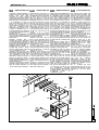
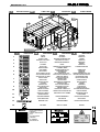
GENERATORE GG1
Posizionare il “GEN” lateralmente o
posteriormente accanto alla cabina,
tenendo
conto
della
spazio
necessario per il “DEP”. Apporre
sopra a questo il pezzo “GS” facendo
collimare le due parti interne uguali e
fissare dal interno con autoforanti 4,8
x 19. Assemblare su “FR3” con
bulloni 8 x 25 il pezzo “PR”; davanti a
questo il “TF” con bulloni 8 x 25 e
ancora davanti con bulloni 8 x 25 il
pezzo “GA”. Appoggiare il “GEN”
assemblato con la parte “GA” al “TL”
e fissarlo con autoforanti 4,8 x 19.
Procedere dal interno per praticare il
foro d’entrata d’aria che dovrà essere
grande quanto il “GA”.
Montaggio filtri di prefiltraggio aria
“FIT 1): inserire le parti (FIT 1) nelle
guide poste nella parte alta della cella
di presa d’aria.
Montaggio bruciatore “BR”: Il
bruciatore deve essere assemblato
con la propria flangia in alluminio di
corredo (dentro la scatola del “BR”) e
fissato con i bulloni forniti alla flangia
metallica del “GEN” posta a lato.
Montaggio Tubo “TT”: fissare il “TT”
sull’uscita della caldaia in acciaio,
tramite la ghiera girevole a lato del
“TT” con viti autoforanti 4,8 x 32.
Montaggio motorino di riciclo “BE”:
fissare il “BE” sulla parete esterna del
“GS” facendo passare il perno della
“SR” nell’apposito foro del “BE”.
Mantenerlo in posizione verticale e
fissarlo sopra all’omega, tramite la
barretta metallica di supporto, che va
inserita nella parete inferiore del “BE”,
con autoforanti 4,8 x 19.
Serrare con chiave da 10’ il morsetto
universale superiore attorno al perno
della “SR” facendo attenzione che
“SR” sia o tutta chiusa o tutta aperta.
POWER UNIT GG1
Position the Power unit “GEN” on a
side or on the rear next to the booth,
considering the space for the exhaust
unit “DEP”. On the top position the
piece “GS” fitting it on the right
position and fixing it from inside with
self-tapping screws 4,8 x 19. Fix on
the hole “FR3” with bolts 8 x 25 the
piece “PR”; in front of it “TF” with bolts
8 x 25 and again with bolts 8 x 25 the
piece “GA”. Lean the “Power unit”
with the piece “GA” onto “TL” and fix
it with self-tapping screws 4,8 x 19.
Proceed from the inside to make the
air entry hole, which must be as big
as “GA”.
Assembling of the air pre-filtering
filters “FIT 1”: insert the parts (FIT 1)
in the guides situated on the upper
part of the air intake cell.
Assemble of the burner “BR”: the
burner must be assembled with its
own aluminium flange (present in the
burners box) and fixed with the
delivered bolts to the metallic flange
on one side of the “GEN”.
Assemble of the duct “TT”: fix the
“TT” at the stainless steel mouth of
the heat exchanger with the revolving
ring at the side of the “TT” with selftapping screws 4,8 x 32.
Assembling of the recycling motor
“BE”: fix the “BE” on the outside wall
of “GS” passing the pin of “SR” in the
proper hole on the “BE”. Maintain it
in vertical position fixing it on the
“Omega” with the metallic bar, which
must be inserted in the lower part of
the “BE”, with self-tapping screws 4,8
x 19.
Lock with a 10’ spanner the universal
spindle clamp around the pin of the
“SR”, taking care that the shutter is
totally open or totally closed.
F
GÉNÉRATEUR GG1
Positionnez le "GEN” latéralement ou
postérieurement à côté de la cabine,
en considérant l’espace nécessaire
pour le “DEP”. Mettez sur le GEN la
pièce “GS” en faisant affleurer les
deux parties intérieures égales et
fixez de l’intérieur avec des vis autoperçantes 4,8 x 19. Assemblez sur
“FR3” avec des boulons 8 x 25 la
pièce “PR”; devant PR le “TF” avec
les boulons 8 x 25 et encore devant
avec les boulons 8 x 25 la pièce
“GA”. Appuyez le “GEN” assemblé
avec la partie “GA” au “TL” et fixez-le
avec des vis auto-perçantes 4,8 x 19.
Procédez de l’intérieur pour pratiquer
le trou d’entrée de l’air qui devra être
aussi grand que le “GA”.
Assemblage des filtres de préfiltrage
de l’air “FIT 1): insérez les parties
(FIT 1) dans les guides placées dans
la partie haute de la cellule de prise
de l’air.
Assemblage du brûleur “BR”: le
brûleur doit être assemblé avec son
propre bride fourni en aluminium (à
l’intérieur de la boîte du “BR”) et fixé
avec les boulons fournis au bride
métallique du “GEN” placé à côté.
Assemblage du Tube “TT”: fixez le
“TT” sur la sortie de la chaudière en
acier, au moyen de la frette tournante
à côté du“TT” avec des vis autoperçantes 4,8 x 32.
Assemblage du moteur de recyclage
“BE”: fixez le “BE” sur la paroi
extérieure du “GS” faisant passer le
pivot de la “SR” dans le spécial trou
du “BE”. Maintenez-le en position
verticale et fixez-le sur l’oméga, par le
barreau métallique qui doit être
inséré dans la paroi inférieure du
“BE” avec des auto-perçantes 4,8 x
19. Serrez avec une clef de 10’ la
noix d’entraînement universelle
supérieure autour du pivot de la “SR”
en faisant attention que “SR” soit
complètement
fermée
ou
complètement ouverte.
D
ZULUFTAGGR GG1
Das Aggregat “GEN” seitlich oder
hinter der Kabine aufstellen, Platz
lassend für den “DEP”. Oben drauf
das Teil “GS” setzen und von innen
mit selbstschneidenden Schrauben
4,8 x 19 vereinen. Auf “FR3” das Teil
“PR” setzen und mit 8 x 25 Bolzen
befestigen; vor diesem das Teil “TF”
mit 8 x 25 Bolzen befestigen und
dann das Teil „GA“ mit 8 x 25 Bolzen
befestigen. Das Aggregat “GEN” mit
dem befestigten Teil “GA” an “TL”
lehnen und mit selbstschneidenden
Schrauben 4,8 x 19 befestigen. Von
innen die Lufteingansöffnung so groß
wie “GA” ausschneiden.
Einbau der Vorfilter: die Teile “FIT 1”
in den Falzen in dem oberen Teil der
Lufteinführungszelle einfügen.
Montage des Brenners “BR”: der
Brenner soll mit seiner Flansch aus
Aluminium, welche sich in dem
Kartons des “BR” befindet) mit den
gelieferten Bolzen and die seitlich
positionierte Flansch des “GEN”
befestigt werden.
Montage des Rohres “TT”: das Teil
“TT” an den Ausgang des
Wärmeaustauschers aus rostfreiem
Stahl mit der drehbaren Nutmutter
zur Seite, mit selbstschneidenden
Schrauben 4,8 x 32 befestigen.
Montage des Luftmlaufmotors: den
“BS” an die Außenwand des ”GS”
befestigen, mit dem Zapfen “SR” in
der eigens bestimmten Öffnung des
“BE”.
Mit
dem
metallenen
Stützstäbchen, welches in dem
unteren Teil des „BE“ eingefügt wird,
in vertikaler Position auf die Platte in
„Omega“ Form befestigen mit den
Schrauben 4,8 x 19.
Mit 10´ Schlüssel das obere
Universal-Klemmbock rund um den
Zapfen der “SR” anziehen bei ganz
geschlossener oder ganz offener
„SR“.
FR1
GA
TF
PR
GS
FR3
SR
BE
TT
BR
GEN
FIT1
SAIMA
I
28
SAIMA
MECCANICA S.P.A.
DEPURATORE DG1
Montaggio depuratore “DEP” con
base: appoggiare il “GA” al
fascione, segnare e praticare il
foro dall’esterno quindi fissare
con autoforanti 4,8 x 19.
Appoggiare al “GA” il “BD” quindi
fissare con bulloni 8 x 25.
Appoggiare il “DEP” sopra al
“FR3” e fissarlo dall’interno con
autoforanti 4,8 x 25. Fissare la
“STD” nella parte di sopra
appoggiandola alla bocca del
ventilatore
e
fissarla
con
autoforanti 4,8 x 32. La taratura
iniziale 50% sarà modificata in
base
all’assorbimento
del
motore.
Montaggio filtri all’interno “DEP”:
inserire nella guida più in basso i
filtri “FC” con la parte verde
rivolta verso il basso. Inserire i
filtri “FIT2” sulla guida più alta.
Chiudere lo sportello (SP) con le
chiusure poste nei montanti.
GB
F
EXHAUST UNIT DG1
Assembling of the exhaust unit
“DEP” with base: lean “GA”
against to the beam; sign and
make the hole from the outside
and fix with self-tapping screws
4,8 x 19. lean “GA” against to
“BD” and fix with bolts 8 x 25.
Lay the “DEP” on the “FR3” and
fix from the inside with selftapping screws 4,8 x 25. Fix
“STD” on the top over the
ventilators mouth with selftapping screws 4,8 x 32. The
initial setting of 50% will be
modified in base of the
absorption of the motor.
Assembling of the filters in the
inside of the “DEP”: insert in the
lower guide the filters “FC” with
the green side turned to the
bottom. Insert the filters “FIT2” in
the upper guide. .
Close the shutter (SP) with the
lock on the rods.
EPURATEUR DG1
Assemblage
de
l’épurateur
“DEP” avec la base: appuyez le
“GA” au “A1”; marquez et
pratiquez le trou de l’extérieur;
donc, fixez avec des vis autoperçantes 4,8 x 19. Appuyez sur
“GA” le “BD”, donc fixez avec
des boulons 8 x 25. Appuyez le
“DEP” sur le “FR3” et fixez-le de
l’intérieur avec des vis autoperçantes 4,8 x 25. Fixez la
“STD” dans la partie supérieure
en l’appuyant sur la bouche du
ventilateur et fixez-la avec des
auto-perçantes 4,8 x 32. Le
tarage initial du 50% sera modifié
selon l’absorption du moteur.
Assemblage
des
filtres
à
l’intérieur “DEP”: insérez dans la
guide inférieure les filtres “FC”
avec la partie verte tournée vers
le bas. Insérez les filtres “FIT2”
sur la guide supérieure (vide au
centre). Fermez le guichet (SP)
avec les fermetures placées
dans les montants.
D
ABLUFTAGGR DG1
Montage des Abluftaggregates
“DEP” mit Unterbau: “GA” an den
Balken
lehne,
das
Loch
einzeichnen und von außen
ausschneiden
und
mit
selbstschneidenden Schrauben
4,8 x 19 befestigen. An “GA” den
“BD” lehnen und mit Bolzen 8 x
25 befestigen. Den „DEP“ auf
“FR3” setzen und von innen mit
selbstschneidenden Schrauben
4,8 x 25 befestigen. Die “STD”
auf die Öffnung des Ventilators
mit Schrauben 4,8 x 32
befestigen. Die Einstellung 50 %
wird je nach Absorption des
Motors verändert.
Montage der Filter im “DEP”: in
die untere Falze die Filter “FC”
mit der grünen Seite nach unten
und die „FIT2“ in die obere
schieben.
Die Klappe
(SP) mit den
Verschlüssen auf den Pfeilern
schließen
STD
DEP
FIT2
FC
FR2
SP
FR3
GA
BD
SAIMA
I
29
SAIMA
MECCANICA S.P.A.
LUCI 01
Montaggio scatola porta luci
“SCA”: fissare la “SCA” sulle “PL”
e “P1/P2/P3” con il foro che si
trova lateralmente verso il basso
usando le viti con testa a croce
4,2 x 13 autoforanti.
Montaggio plafoniera interna con
neon “PLA”: alloggiare “PLA”
all’interno di “SCA” con la piega
dal lato lungo verso il basso per
passaggio dei cavi. Dopo averla
collegata elettricamente fissarla
con la vite 4 x 20 tramite il foro
sul centro del lato lungo
superiore.
Montaggio vetro “SCA” “PLA”
“VTR”: incollare la guarnizione
mousse 18 x 13 autoadesiva
nell’incavo intorno al “VTR”;
appoggiare il “VTR” sulla sede
della “SCA” e avvitarlo con le viti
a testa brugola da 5 x 25.
Fissare la plafoniera assemblata
con viti a testa piatta in
dotazione.
GB
LIGHTS 01
Assembling of the fixture box
“SCA”: fix the “SCA” on the “PL”
and “P1/P2/P3” with the side
hole on the lower part with selftapping screws with cros head
4,2 x 13 .
Assembling of the light fixture
“PLA”: insert “PLA” in the “SCA”
with the fold on the longer side
towards the bottom for cable
passage. After done the electric
connection fix with the 4 x 20
screws using the central hole on
the longer upper side.
Assemble of the glasses “SCA”
“PLA” “VTR”: stick the selfadhesive gasket mousse 18 x
13 into the groove around the
“VTR”; lean the “VTR” against to
the “SCA” fixing with the allen
screw 5 x 25.
Fix the assembled light fixture
with the delivered flathead
screws.
F
LUMIÉRES 01
Assemblage du bloc d’éclairage
“SCA”: fixez la “SCA” sur le “PL”
et “P1/P2/P3” avec le trou qui se
trouve latéralement vers le bas
en utilisant les vis cruciformes
4,2 x 13 auto-perçantes.
Assemblage du bloc d’éclairage
intérieur avec le néon “PLA”:
logez “PLA” au dedans de “SCA”
avec le pli du côté longue vers le
bas pour le passage de câbles.
Après sa connexion électrique,
fixez-la avec la vis 4 x 20 par le
trou sur le centre du côté longue
supérieur.
Assemblage du carreau “SCA”
“PLA” “VTR”: collez la garniture
mousse 18 x 13 autoadhésive
dans le cran autour du “VTR”;
appuyez le “VTR” sur le siège de
la “SCA” et vissez-le avec les vis
à six pans creux de 5 x 25.
Fixer le bloc d’éclairage monté
par les vis à tête plate fournies.
D
LEUCHTEN 01
Montage
der
Leuchtenbox:
“SCA” auf “PL” und “P1/P2/P3”
befestigen mit dem seitlichen
Loch
nach
unten
mit
selbstschneidenden 4,2 x 13
Kreuzschlitzschrauben.
Montage der Röhrenbox “PLA”:
in “SCA” einfügen mit der Falte
auf der längeren Seite nach
unten für den Durchgang der
Kabel. Nach der elektrischen
Anschließung mit der Schraube 4
x 20 und dem zentralen Loch
auf der oberen längeren Seite
befestigen.
Montage der Gläser “SCA” “PLA”
“VTR”:
Die
selbsthaftende
Schaumdichtung 18 x 13 in der
Vertiefung um “VTR” einkleben;
“VTR” an “SCA” lehnen und mit
den
Innensechskantigen
Schrauben 5 x 25 befestigen.
Die fertige Leuchte mit den
gelieferten
Senkschrauben
befestigen.
TLUX
x12
SCA
PLA
VTR
BLUX
x11 + PS
x12
SCA
PLA
VTR
SAIMA
I
30
SAIMA
MECCANICA S.P.A.
COMPLEMENTI CG1
Posizionamento misuratore di
pressione, sonda temperatura,
quadro di comando e serigrafie
Saima.
GB
ACCESSORIES CG1
Positioning of the pressure
guage,
temperature
feeler,
control panel and serigraphy
Saima.
F
COMPLEMENTS CG1
D
ZUBEHÖR CG1
Positionnement du mesureur de Position des Druckmessers, der
pression, de la sonde de Temperatursonde, der Schalttempérature, du tableau de bord Tafel und der Aufschrift Saima.
et des sérigraphies Saima.
LO
x1
LO
SAIMA
I
31
MECCANICA S.P.A.
I
SAIMA
VARIE
Per completare il montaggio della cabina di verniciatura vanno effettuati ancora alcuni passi fondamentali:
A) SIGILLATURA DELL’IMPIANTO: Utilizzando i tubi di SIGILLANTE non siliconico forniti con la cabina di verniciatura,
passare su tutte le giunture dei vari pezzi visibili, sia internamente che esternamente alla cabina di verniciatura, salvo
all’interno delle cavità delle plafoniere e sulle parti mobili, in modo che sia assicurata la tenuta alle polveri (Es: doppie C –
tetto inclinati – telai portafiltri – telai porte - canalizzazioni – etc.).
ATTENZIONE!!
LA CABINA DI VERNICIATURA PRODOTTA DALLA SAlMA MECCANICA SPA NON È IN ALCUN MODO IMPERMEABILE, NÈ PRODOTTA PER ESSERE MONTATA IN AMBIENTE ESTERNO, SALVO CHE NON SIA FORNITA
CON APPOSITA TETTOIA.
B) INSTALLAZIONE DEI VETRI: in corrispondenza di ogni oblò delle porte e delle pareti, vanno installati i vetri in
dotazione utilizzando la guarnizione fornita. Incastrando i bordi liberi degli oblò nella guarnizione, non rimarrà che inserire il
vetro nella parte di guarnizione libera. Gli sportelli luci hanno i vetri già montati.
C) FILTRI, PORTAFILTRI E GRIGLIE: installarli negli appositi alloggiamenti:
1- Aprire il pannello della cella di prefiltraggio del gruppo generatore, infilare nelle apposite guide i telaietti di filtri a tasche
di prefiltraggio, richiudere (a seconda del modello) i fermi in plastica o avvitare i pomelli..
2- Negli appositi vassoi porta-filtri, appoggiare i filtri del cielo, quindi appoggiare i vassoi in un incastro libero e avvitare i
pomelli e/o i bulloni (a seconda del modello) per fissarlo.
3- Nei telai sottogriglia, appoggiare gli appropriati filtri paint stop con il colore bianco in alto, depositare i telai sul bordo
interno delle fosse di deflusso e ricoprire con le griglie portanti le fosse stesse.
D) COLLEGAMENTI ELETTRICI: posizionare la plancia di comando in prossimità della porta principale della cabina di
verniciatura, di modo che i comandi ivi contenuti, siano accessibili in modo comodo dall’operatore, quindi collegare il cavo
multifilare a seconda del modello, le varie cavetterie provenienti da motori, sensori, bruciatore e plafoniere nelle apposite
morsettiere, vedi schema elettrico allegato all’interno del cassone di potenza, quindi collegare il quadro stesso alla rete
elettrica. Tutti i cavi esterni devono passare attraverso scatole di derivazione e canalette o guaine.
RICHIAMO: come specificato all’inizio del presente manuale, in molti paesi il montaggio del presente impianto deve essere
effettuato da personale professionalmente qualificato. Anche ove non specificamente richiesto dalla legge la SAlMA
Meccanica SpA consiglia vivamente di seguire questa linea di condotta, declinando ogni responsabilità su infortuni subiti
durante il montaggio della cabina di verniciatura da Lei acquistata ed eventuali futuri malfunzionamenti della stessa.
VARIOUS
In matter to complete the assembling of the spray booth some other fundamental steps must be carried out:
A) SEALING OF THE PLANT: Using the tubes of not silicone sealant delivered with the spray booth, seal all joints from the
different visible pieces, inside and outside of the spray booth, excluding the cavity in the light fixtures and movable parts in
matter to ensure the sealing against dust (Ex: double C – inclined roof – filter-holder frames – door frames - canalisation –
etc.).
ATTENTION!
THE SPRAY BOOTH PRODUCED BY SAlMA MECCANICA SPA ISN’T IMPERMEABLE AND NOT PRODUCED TO BE
ASSEMBLED IN AN EXTERNAL ENVIRONMENT, EXCEPT IF DELIVERED WITH THE PROPER ROOFING.
B) INSTALLATION OF THE GLASSES: in every porthole of the doors and walls, there will be installed the delivered
glasses using the supplied gaskets. Insert the free edges of the portholes in the gasket and insert the glasses in the free
part of the basket. The light fixture glasses are already assembled.
C) FILTERS, FILTER-HOLDERS AND GRIDS: install them in the proper housings.
1- Open the panel of the power unit pre-filtering cell, insert in the proper guides the frames with the pre-filtering pocket,
close again (depending from the model) with the plastic locks or screw the knobs.
2- Lay the ceiling filter in the proper filter holder trays and than insert the trays in one free dap and screw the knobs and or
the bolts (depending from the model) to fix it.
4- Insert the paint-stop filter in the under-grid frames with the white side to the top, deposit the frames on the inner border
of the air outflow pits and cover with the bearing grids the same.
D) ELECTRIC CONNECTIONS: position the control panel near by to the main entrance of the spray booth, so that the
present pushbuttons are easily accessible for the operator. Connect the multi-wire cable as required for each model, the
several cables coming from the motor, feelers, burner and light fixtures to the proper terminal boards, as shown on the
electrical diagram in the power box and than connect the panel itself to the electric system. All external cables must pass
through junction boxes and sheath or raceways.
REMARK: as specified at the beginning of the present handbook, in many countries professional and qualified technicians
must do the assembling. Also where it is not specifically required by the law SAlMA Meccanica SpA suggest to follow this
line of conduct, refusing all responsibilities on accidents on work during the assembling of the spray booth bought by you
and eventual faulty operations of the same in the future.
SAIMA
GB
32
MECCANICA S.P.A.
F
SAIMA
DIVERS
Pour compléter l’assemblage de la cabine de peinture, il faut exécuter encore quelques passages fondamentaux:
A) CACHETAGE DE L’INSTALLATION: En utilisant des tubes de mastic non silicone pour cacheter fournis avec la cabine
de peinture, passez sur toutes les jointures des plusieurs pièces visibles, soit à l’intérieur soit à l’extérieur de la cabine de
peinture, sauf à l’intérieur des cavités des plafonniers et sur les parties mobiles de façon à assurer l’étanchéité aux
poussières (Par exemple: doubles C – toits inclinés – châssis porte-filtres – châssis des portes – canalisations – etc.).
ATTENTION!!
LA CABINE DE PEINTURE PRODUITE PAR SAlMA MECCANICA SPA N’EST PAS IMPERMEABLE, NI PRODUITE
POUR ETRE ASSEMBLEE DANS UN MILIEU EXTERIEUR, SAUF SI ELLE EST FOURNIE DE LA SPECIALE TOITURE.
B) MISE EN PLACE DES CARREAUX: en correspondance de chaque hublot des portes et des parois, installez les
carreaux fournis en utilisant la garniture fournie. En encastrant les bords libres des hublots dans la garniture, insérez le
carreau dans la partie libre de la garniture. Les carreaux des guichets des lumières sont déjà assemblés.
C) FILTRES, PORTE-FILTRES ET GRILLES: il faut les installer dans les spéciaux logements:
1- Ouvrez le panneau de la cellule de préfiltrage du groupe générateur, insérez dans les spéciales guides les petits
châssis de filtres à poche de préfiltrage, refermez (selon le modèle) les arrêts de sûreté en plastique ou vissez les
poignées.
2- Dans les spéciaux plateaux porte-filtres, appuyez les filtres du ciel, donc appuyez les plateaux dans un encastrement
libre et vissez les poignées et/ou les boulons (selon le modèle) pour le fixer.
5- Dans les châssis sous-grille, appuyez les spéciaux filtres paint-stop avec la couleur blanche en haut, déposez les
châssis sur le bord intérieur des fosses d’écoulement et recouvrez avec les grilles portantes les fosses mêmes.
D) CONNEXIONS ELECTRIQUES: positionnez le tableau de bord à proximité de la porte principale de la cabine de
peinture, afin que les commandes contenues soient accessibles confortablement par l’opérateur; donc, connectez le câble
à fils multiples selon le modèle, les assortiments de câbles qui proviennent des moteurs, capteurs, du brûleur et des
plafonniers dans les boîtes à bornes (voir le diagramme ici joint) à l’intérieur du caisson de puissance. Donc, connectez le
tableau au réseau électrique. Tous les câbles extérieurs doivent passer par les boîtes de dérivation et les rigoles ou gaines.
RAPPEL: comme on a spécifié au début de ce Manuel, dans plusieurs pays l’assemblage de cette installation doit être
exécutée par personnel professionnellement qualifié. Même si la loi ne prescrit rien de spécifique à cet égard, SAlMA
Meccanica SpA conseille vivement d’observer cette ligne de conduite, en déclinant toutes responsabilités en ce qui
concerne les accidents subis pendant l’assemblage de la cabine de peinture que vous avez acheté et sur possibles mal
fonctionnements futurs de la même.
VERSCHIEDENES
Um die Montage der Lackierkabine zu beenden sind noch einige grundlegende Schritte durchzuführen:
A) ABDICHTUNG DER ANLAGE: die Lackierkabine mit dem nicht Silikon enthaltenen gelieferten Abdichtungsmaterial an
allen sichtbaren Zusammenfügungen abdichten, von innen und von außen, außer in den inneren Hohlräumen der Leuchten
und der beweglichen Teilen, damit die beste Versiegelung gegen Staub gewährleistet wird (z. B.: Doppel “C” –
schrägsitzende Deckenteile – Filterrahmen – Türrahmen – Schächte – u s w).
ACHTUNG!!
DIE VON DER SAIMA MECCANICA SPA HERGESTELLTE LACKIERKABINE IST NICHT WASSERDICHT UND NICHT
GEBAUT WORDEN UM IM FREIEN ZU STEHEN, AUßER SIE WURDE MIT DEM EIGENS DAZU BESTIMMTEN
WETTERDACH GELIEFERT.
B) INSTALLIERUNG DER GLÄSER: in jedes Bullauge der Tore und Wände werden die gelieferten Gläser eingebaut mit
den dazu gehörenden Dichtungen. Nach der Einfügung der freien Ränder der Bullaugen in die Gummidichtungen die
Gläser in die Dichtung einfügen. Die Gläser der Leuchten werden schon eingebaut geliefert.
C) FILTER, FILTERRAHMEN UND GITTER: in die dazu bestimmten Stellen einbauen.
1- Die Vorfilterungszelle des Zuluftaggregates öffnen, in die dazu bestimmten Schienen die Rahmen mit den Vorfiltern
einfügen und schließen (je nach Modell) mit dem Kunststoffverschluß oder mit dem Knauf festschrauben.
2- Die Deckenfilter in die dazu bestimmten Tabletten legen, danach die Tablette in die freien Plätze einfügen und mit den
Knäufen oder Bolzen (je nach Modell) festschrauben.
3- In die Untergitterfilterrahmen die Paint-stop Filter mit der weißen Farbe nach oben legen, die Rahmen auf die innere
Kante der Abluftgruben setzen und mit den tragenden Gittern dieselben abdecken.
D) ELEKTRISCHE ANSCHLÜSSE: Die Schalttafel in die Nähe der Haupteinfahrt der Lackierkabine befestigen, so daß ein
leichter Zugang zu den Schaltknöpfen gewährleistet wird und danach den mehradrigen Kabel je nach Modell anschließen,
die verschiedenen Kabel die von den Motoren, Sensoren, Brenner und Leuchten zu den Klemmleisten führen und nach
dem Schema der in dem Kraftschaltschrank liegt anschließen. Alle externen Kabel müssen durch Abzweigmuffen und
Hüllen geführt werden.
BEMERKUNGEN: so wie schon in der Einführung angegeben wurde, muß die Montage in vielen Ländern ausschließlich
durch professionellem und qualifiziertem Personal durchgeführt werden. Auch da wo die Gesetze es nicht verlangen ratet
SAlMA Meccanica SpA diese Vorschrift zu verfolgen, jegliche Verantwortung über Arbeitsunfällen während des Aufbaues
der Anlage und zukünftige Funktionsstörungen der selben zurückweisend.
SAIMA
D
33
SAIMA
I
1.
2.
3.
4.
5.
6.
7.
8.
9.
10.
11.
12.
13.
14.
15.
16.
17.
18.
19.
20.
21.
22.
23.
24.
25.
26.
27.
28.
29.
30.
IMPIANTO
ELETTRICO
Cavo antifiamma 3 x 1,5
Fissaggio cavo antifiamma
(moto ridutt., bruciatore)
Guaina Ø 12
Cavo antifiamma 4 x 1,5
Cavo antifiamma 4 x 1,5
Cavo antifiamma 3 x 1,5
Cavo antifiamma 3 x 1,5
Guaina Ø 22
Guaina Ø 22
Guaina Ø 22
Guaina Ø 22
Scatola derivazione
Scatola derivazione
Scatola derivazione
Scatola derivazione
Scatola derivazione contenimento termostato
Quadro di comando
Motore gruppo generatore
Bruciatore
Motoridutt. regolatore aria
verniciatura- essiccazione
Micro serranda tagliafuoco
Cavo antifiamma 4 x Ø a
seconda del motore
Guaina Ø 22
Motore gruppo estrattore
Quadro di potenza
Guaina Ø 12
Sonda di temperatura
Guaina antifiamma Ø 12/16
Passacavo a pastiglia (usare nei passaggi lamiera)
Passaggio della sonda di
temperatura
GB
ELECTRIC
INSTALLATION
1. 3 x 1,5 fireproof cable
2. Flame retardant cable fastener
(gear motor, burner, etc. )
3. Ø 12 sheath
4. Fireproof cable 4x1,5
5. Fireproof cable 4x1,5
6. Fireproof cable 4x1,5
7. Fireproof cable 4x1,5
8. Ø 22 sheath
9. Ø 22 sheath
10. Ø 22 sheath
11. Ø 22 sheath
12. Electrical junction box
13. Electrical junction box
14. Electrical junction box
15. Electrical junction box
16. Thermostat electrical
junction box
17. Control panel
18. Power unit motor
19. Burner
20. Gear motor air adjusting in
Painting/drying
21. Fire-damper micro switch
22. Fire-proof cable 4 x Ø
depending from the motor.
23. Ø 22 sheath
24. exhaust unit motor
25. Power Control panel
26. Ø 22 sheath
27. Temperature feeler
28.Ø12/16 flame retard sheath
29. Plug-nut core hitch (to be
used in the sheet ducts)
30. Temperature feeler duct
passage
F
INSTALLATION
ELÉCTRIQUE
1. Câble anti-flame 3 x 1,5
2. Fixage du câble anti-flamme
(moto réductrice, brûleur)
3. Gaine Ø 12
4. Câble anti-flamme 4 x 1,5
5. Câble anti-flamme 4 x 1,5
6. Câble anti-flamme 3 x 1,5
7. Câble anti-flamme 3 x 1,5
8. Gaine Ø 22
9. Gaine Ø 22
10. Gaine Ø 22
11. Gaine Ø 22
12. Boîte de dérivation
13. Boîte de dérivation
14. Boîte de dérivation
15. Boîte de dérivation
16. Boîte de dérivation avec
Thermostat
17. Tableau de commande
18. Moteur Groupe Générateur
19. Brûleur
20. Moto réductrice. Régulation.
Air Peint/Séchage.
21. Micro rideau coupe-feu
22. Câble anti-flamme 4 x Ø
dépends du moteur
23. Gaine Ø 22
24. Moteur Groupe Extracteur
25. Tableau de puissance
26. Gaine Ø 12
27. Sonde de température
28. Gaine anti-flamme Ø 12/16
29. Chaumard à pastille (utiliser
dans les passages en tôle)
30. Passage de la sonde de
température
D
ELEKTRISCHE
ANLAGE
1. Feuerhemmendes Kabel 3x1,5
2. Kabelbefestigung (Brenner,
Bewegungsverminderer).
3. Hülle Ø 12
4. Feuerhemmender Kabel 4x1,5
5. Feuerhemmender Kabel 4x1,5
6. Feuerhemmender Kabel 3x1,5
7. Feuerhemmender Kabel 3x1,5
8. Hülle Ø 22
9. Hülle Ø 22
10. Hülle Ø 22
11. Hülle Ø 22
12. Abzweigmuffe
13. Abzweigmuffe
14. Abzweigmuffe
15. Abzweigmuffe
16. Abzweigmuffe mit
Thermostat
17. Schalttafel
18. Motor des Zuluftaggregates
19. Brenner
20. Bewegungsverminderer der
Luftklappe (Lackier-Trocken)
21. Brandschutzklappe Micro
22. Feuerhemmender Kabel 4 x
Ø je nach Motortyp.
23. Hülle Ø 22
24. Motor des Abluftaggregates
25. Kraftschaltafel
26. Hülle Ø 12
27. Temperatursonde
28. Hülle Ø 12/16
29. Gummiring als Schutz in
Metalldurchgängen
30. Einführung der TemperaturSonde
SAIMA
MECCANICA S.P.A.
34
SAIMA
MECCANICA S.P.A.
I
ETICHETTATURA
GB
F
LABELLING
D
ÉTIQUETER
2
ETIKETTIEREN
13
15
15-17-6
12
14
1
2
3
4
5
INDICAZIONI
GB
16
14
14
F
INDICAZIONI
INDICAZIONI
D
INDICAZIONI
VIETATO
FUMARE
DO NOT
SMOKE
DÉFENSE
DE FUMER
RAUCHEN
VERBOTEN
VIETATO
DEPOSITARE
DO NOT STORE
MATERIALS OR TOOLS
DÉFENSE DE DEPOSER DES
MATERIAUX ET OUTILS
LAGERN
VERBOTEN
DO NOT EAT
OR DRINK
DÉFENSE DE MANGER ET
BOIRE
ESSEN UND
TRINKEN
VERBOTEN
L'USO DI
FIAMME LIBERE
DO NOT USE
NAKED FLAMES
DÉFENSE DE INTRODUIRE DES
FLAMMES LIBRES
FLAMMEN VERBOTEN
VIETATO
L'INGRESSO
a tutte le persone
non autorizzate
AUTHORIZED
PEOPLE ONLY
MATERIALI O ATTREZZI
IN QUESTO LOCALE
E' VIETATO
MANGIARE E BERE
VIETATO
DO NOT DIRECT WATER
JETS AGAINST MOTORS
AND ELETTRICAL LINES
6
ENTRÉE INTERDITE AUX
PERSONNES NONAUTORISEES
NE PAS DIRIGER DE JETS
D’EAU SUR LE MOTEUR ET LA
LIGNE ELECTRIQUE
LES CHAUSSURES DE
SÉCURITÉ SONT
OBLIGATOIRES
UNBEFUGTES
BETRETEN
VERBOTEN
KEINEN WASSERSTRAHL AUF
MOTORE UND ELEKTRISCHE
LEITUNGEN RICHTEN
7
CALZATURE
DI SICUREZZA
OBBLIGATORIE
SAFETY SHOES
OBLIGATORY
8
INDOSSARE
GLI INDUMENTI
PROTETTIVI
USE PROTECTIVE
CLOTHES
ENDOSSER LES VETEMENTS
DE PROTECTION
SCHUTZANZÜGE
TRAGEN
RESPIRATORY
TRACT PROTECTION
OBLIGATORY
IL EST OBLIGATOIRE DE
PROTEGER LES VOIES
RESPIRATOIRES
ATEMWEGE
SCHÜTZEN IST
OBLIGATORISCH
10
BEFORE STARTING
CHECK EARTHING
CONTROLER LA MISE A LA
TERRE AVANT DE TRAVAILLER
VOR DEM BEGINN ERDUNG
KONTROLLIEREN
11
VEHICLES AT MAN’S
WALKING SPEED
VEHICULES A PAS D’HOMME
FAHRZEUGE NUR IM
SCHRITTEMPO
12
GRATINGS MAXIMUM
LOAD RESISTANCE
CHARGE MAXIMUM DU
CAILLEBOTIS
HÖCHSTTRAGFÄHIGKEIT
DES GITTERS
13
MAXIMUM LOAD
CHARGE MAXIMUM
HÖCHSTTRAGFÄHIGKEIT
14
EARTHING
MISE A LA TERRE
ERDUNG
9
15
16
INDICATORE (AR) ITALIA Tel. 0575/9291
PIANO DI MANUTENZIONE ORDINARIA
17
PIANO DI MANUTENZIONE
ORDINARIA
GENERAL MAINTENANCE
PLAN
INDICATORE (AR) ITALIA Tel. 0575/9291
MATRICOLA
ALLGEMEINER
WARTUNGSPLAN
TIPO
FILTRI CIELO
ANNO
VOLT
VOLT luci
Hz
PLAN D’ENTRETIEN
ORDINAIRE
UNFALLSCHUHE SIND
OBLIGATORISCH
FASE
CAL/h
GRUPPO GENERATORE
DEPURATORE
PORTATA ARIA mch
PORTATA ARIA mch
POTENZA Kw
POTENZA Kw
MASSA
MASSA
Kg
SAIMA
I
14
15-17-6
16
14
1-2-3-4-5-7-8-9-10-11
14
Kg
35