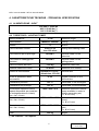
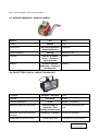
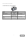
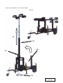
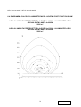
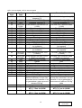
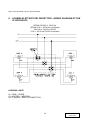
1
MANUALE D’ISTRUZIONE
OWNER’S MANUAL
Mod. MTLC 10mt 4x1000W
Mod. MTLC 10mt 4x1500W
TL009-01-00-01
08-06-2006
MTLC 10mt 4x1000W – MTLC 10mt 4X1500W
INDICE - INDEX
1. USO E MANUTENZIONE – USE & MAINTENANCE .......................................................... 3
2. INFORMAZIONI GENERALI - GENERAL INFORMATION................................................ 4
2.1
DOCUMENTAZIONE A CORREDO DELLA TORRE FARO - EQUIPMENT DOCUMENTATION
OF THE LIGHTING TOWER ..................................................................................................................................... 4
3. DESCRIZIONE GENERALE DELLA MACCHINA - GENERAL DESCRIPTION OF
THE MACHINE ........................................................................................................................... 5
4. CARATTERISTICHE TECNICHE - TECHNICAL SPECIFICATION ................................. 6
4.1
4.2
4.3
4.4
4.5
ALIMENTAZIONE - INPUT.......................................................................................................................... 6
TORRE FARO - LIGHTING TOWER ......................................................................................................... 6
ARGANO MANUALE - MANUAL WINCH ................................................................................................. 7
PROIETTORE 1000 W - 1000 W FLOODLIGHT..................................................................................... 7
PROIETTORE 1500 W - 1500 W FLOODLIGHT..................................................................................... 8
5. CARATTERISTICHE DELL’ARGANO - SPECIFICATION OF THE WINCH .................. 9
6. ISTRUZIONE PER L’USO - OPERATING INSTRUCTIONS ............................................ 10
6.1
CONTROLLI PER L’UTILIZZO - CONTROL BEFORE TO USE ......................................................... 10
6.2
PREPARAZIONE ALL’UTILIZZO DELLA TORRE FARO - INSTRUCTION FOR THE USE OF
THE LIGHTING TOWER.......................................................................................................................................... 11
6.3
ALLACCIAMENTO ELETTRICO - ELECTRICAL CONNECTION ...................................................... 15
6.4
DIAGRAMMA CALCOLO ILLUMINOTECNICO - LIGHTING FOOT PRINT DIAGRAM ................. 16
7. RICAMBI - PARTS LIST ......................................................................................................... 17
8. SCHEMA ELETTRICO DEI PROIETTORI - WIRING DIAGRAM OF THE
FLOODLIGHTS ........................................................................................................................ 20
2
TL009-01-00-01
08-06-2006
MTLC 10mt 4x1000W – MTLC 10mt 4X1500W
1. USO E MANUTENZIONE – USE & MAINTENANCE
Prima di installare la macchina e in ogni
caso prima di qualsiasi operazione,
leggere attentamente il seguente manuale
d’istruzione ed uso, nel caso in cui quanto
riportato non fosse perfettamente chiaro o
comprensibile, interpellare direttamente la
casa produttrice.
Before install the machine and however
before every operation, read carefully the
following manual of instruction and use , if
this manual were not perfectly clear or
comprehensible, contacted directly house
manufacturer.
Il presente manuale d’istruzione è parte
integrante della macchina e deve perciò
seguire il ciclo di vita della macchina per
10 anni dalla messa in servizio, anche in
caso di trasferimento della stessa ad un
altro utilizzatore.
The present manual of instruction is
integrating part of the machine and must
follow the cycle of life of the machine for
10 years from the putting in service, also
in case of transfer of the same one to an
other user.
Tutti i dati e le loro fotografie del
presente catalogo possono essere
soggetti a modifiche senza impegno di
preavviso.
Specifications and pictures of the
present catalogue, are subject to
modification without prior notice.
3
TL009-01-00-01
08-06-2006
MTLC 10mt 4x1000W – MTLC 10mt 4X1500W
2. INFORMAZIONI GENERALI - GENERAL INFORMATION
La torre faro è stata progettata, costruita e
collaudata per soddisfare le vigenti
normative Europee nel ridurre al minimo i
rischi elettrici e nel rispetto delle vigenti
norme.
The lighting tower is designed, produced
and tested to meet the European rule
and to reduce at the minimum the
electrical risks in compliance the actually
laws.
2.1 DOCUMENTAZIONE A CORREDO DELLA TORRE FARO - EQUIPMENT
DOCUMENTATION OF THE LIGHTING TOWER
Assieme al presente manuale vengono
forniti i seguenti documenti:
• Manuale d’uso e manutenzione
della torre faro (il presente
manuale).
• Scheda di collaudo per le torri faro.
• Dichiarazione di conformità CE.
Certificato di garanzia
Together at this manual we are supplying
following documents:
• Instruction manual and use for the
lighting tower (this manual).
•
•
4
Check list for the lighting tower.
CE
conformity
declaration.
Warranty certificate.
TL009-01-00-01
08-06-2006
MTLC 10mt 4x1000W – MTLC 10mt 4X1500W
3. DESCRIZIONE GENERALE DELLA MACCHINA - GENERAL
DESCRIPTION OF THE MACHINE
La torre faro modello MTLC 10mt è una
torre d’illuminazione disegnata tenendo in
considerazione
tre
caratteristiche
fondamentali:
• dimensioni abbastanza contenute
• alta affidabilità
• qualità dei materiali costruttivi
The lighting tower MTLC 10mt has been
studied taking in consideration three
fundamental characteristics:
•
•
•
enough contained dimensions
high reliability
quality
of
the
constructive
materials
The constructive materials in uses
guarantee not only an extreme strength of
the tower, but they are also synonymous
of longevity, in fact these materials are
untouchable from the deterioration
phenomena like the rust. The possibility
to lowering the tower is the fundamental
factors in the field of the movement and
the transports. The tower can be used
and installed from a single operator in the
maximum safety. The floodlights bulb’s
used on tower are made from the best
producers in the world and carefully
checked.
I materiali costruttivi utilizzati attribuiscono
non solo un’estrema robustezza alla torre,
ma sono anche una garanzia di longevità,
in quanto tali materiali sono inattaccabili
dai fenomeni di deterioramento quali la
ruggine. La possibilità di abbassare la torre
è un fattore fondamentale nell’ambito della
movimentazione e dei trasporti. La torre
faro può essere utilizzata da un solo
operatore con la massima sicurezza. I
proiettori, completi di lampada, utilizzati
sulle torri faro oltre ad essere forniti dalle
migliori case produttrici sono cablati a
regola d’arte ed accuratamente controllati.
5
TL009-01-00-01
08-06-2006
MTLC 10mt 4x1000W – MTLC 10mt 4X1500W
4. CARATTERISTICHE TECNICHE - TECHNICAL SPECIFICATION
4.1 ALIMENTAZIONE - INPUT
230-240 V 50-60 Hz
400 V 50-60 Hz (*)
110 V 50-60 Hz (*)
4.2 TORRE FARO - LIGHTING TOWER
Altezza massima
Sollevamento
10 mt
Manuale - Manual
Raising
4
Section
Sezioni
Cavo di discesa e salita
Maximum height
Inox 133 fili
Inox 133 wires
Raising and lowering cable
Cavo elettrico per la prolunga
H07RN-F
Electrical cable for the
extension
Cavo elettrico cablaggio dei
proiettori
H07RN-F
Electrical cable for the
lightingsystem
Carico di rottura del cavo
1100 Kg
Maximum cable load
Stabilità massima al vento
80 Km/h
Maximum wind stability
Scatola di connessione
Alluminio 137x120 - Electrical box
Aluminium 137x120
Grado di protezione delle
connessioni
IP 55
Degree protection of the
electrical box
Pressacavo proiettori
PG 11
Presscable of the floodlights
Pressacavo per prolunga
PG 16
Presscable for the extension
1400 x 820 x 970
Maximum dimension internal
(space available in order to
install a generating set)
(L x W x H mm)
Dimensione massima interna
(spazio disponibile per installare
un motogeneratore sul telaio)
(Lu x La x H mm)
Dimensione massima chiusa
(Lu x La x H mm)
3530 x 1450 x 1590
Miximum dimension when
closed
(L x W x H mm)
Dimensione massima aperta
(Lu x La x H mm)
3530 x 1450 x10000
Maximum dimension when
open
(L x W x H mm)
Peso
250 kg
Weight
(*) Su richiesta – On request
6
TL009-01-00-01
08-06-2006
MTLC 10mt 4x1000W – MTLC 10mt 4X1500W
4.3 ARGANO MANUALE - MANUAL WINCH
Modello
501
Model
Codice
244.894
Code
Trattamento
Carico massimo
Trazione
Rilascio
Zincatura galvanica Treatment
Hot-galvanization
500 Kg
Ruotare in senso
orario – Rotate in
right direction
Maximum load
Traction
Release
Ruotare insenso
antiorario – Rotate in
left direction
4.4 PROIETTORE 1000 W - 1000 W FLOODLIGHT
Lampada
Alogena - Halogen
Lamp
Potenza
4x1000 W
Power
Grado di protezione
Materiale costruttivo del corpo
Materiale costruttivo del porta
lampada
Dimensioni (Lu x La x H mm)
IP 55
Degree of protection
Constructor material of the
Pressofusione di
body
alluminio - Diecasting of aluminium
Ceramica - Ceramic Constructor material
355 x 310 x 150
7
Dimension (L x W x H mm)
TL009-01-00-01
08-06-2006
MTLC 10mt 4x1000W – MTLC 10mt 4X1500W
4.5 PROIETTORE 1500 W - 1500 W FLOODLIGHT
Lampada
Alogena - Halogen
Lamp
Potenza
4x1500 W
Power
Grado di protezione
Materiale costruttivo del corpo
Materiale costruttivo del porta
lampada
Dimensioni (Lu x La x H mm)
IP 55
Degree of protection
Constructor material of the
Pressofusione di
body
alluminio - Diecasting of aluminium
Ceramica - Ceramic Constructor material
355 x 310 x 150
8
Dimension (L x W x H mm)
TL009-01-00-01
08-06-2006
MTLC 10mt 4x1000W – MTLC 10mt 4X1500W
5. CARATTERISTICHE DELL’ARGANO - SPECIFICATION OF THE
WINCH
•
SICUREZZA: il carico è sempre
sicuro grazie al freno automatico a
pressione
con
dispositivo
antisrotolamento; il riduttore è
alloggiato al riparo da ogni impurità;
la
nuova
copertura
posta
lateralmente elimina gli spigoli e
protegge dalle sporgenze.
•
SAFETY: the load is always safe
thanks to the automatic pressure
brake with anti-slip mechanism; the
reducer is lodge protected from
every impurity; the new side cover
eliminates the chine and protect it
from dust and dirt.
•
ROBUSTEZZA:
un
nuovo
procedimento di costruzione con
l’ausilio di macchine CNC assicura
la massima qualità e robustezza,
grazie anche all'utilizzo di nuovi
pregiati
materiali;
la
vita
dell'arganello è maggiore grazie
all'irrobustimento del telaio.
•
ROBUSTNESS: a new procedure
of construction with the aid of CNC
Machines assures the maximum
quality and robustness, thanks
also to the use of new valuable
materials; the life of the winch is
increased
thanks
to
the
strengthening of the frame.
•
DURATA: la protezione della
superficie esterna è stata migliorata
grazie
ad
una
nuova
galvanizzazione. Gli agenti frenanti
necessitano di manutenzione (vd.
libretto).
•
DURATION: the protection of the
external
surface
has
been
improved thanks to a new
galvanization. The winches brake
components require maintenance
(see the manual).
•
n.b. E’ importante che, se per
qualsiasi motivo, vi fossero parti non
conformi
o
danneggiate,
l’installatore
non
proceda
all’avviamento della macchina sino
alla risoluzione di tali problemi.
•
n.b. Is important that, for any
problems,
if
there
were
imperfections or damaged parts,
the user does not proceed to the
installation of the machine until to
the resolution of such problems.
9
TL009-01-00-01
08-06-2006
MTLC 10mt 4x1000W – MTLC 10mt 4X1500W
6. ISTRUZIONE PER L’USO - OPERATING INSTRUCTIONS
6.1 CONTROLLI PER L’UTILIZZO - CONTROL BEFORE TO USE
Una volta effettuata l’installazione, è
d’obbligo che tutte le parti della macchina
siano:
Once carried out the installation, is
necessary that all the parts of the
machine are:
•
Perfettamente integre (senza crepe
o difetto alcuni, in particolar modo
l’argano di sollevamento, il cavo di
salita e discesa, le sezioni di tubi ed
i proiettori).
•
Perfectly integral (without leaks or
defect some, in particular way the
manual winch, the stainless steel
cable, the axle of the trailer and
the floodlights).
•
Conformi a quanto riportato in detto
manuale in tutte le loro parti.
•
Exactly to how much written on
this manual in all it parts.
10
TL009-01-00-01
08-06-2006
MTLC 10mt 4x1000W – MTLC 10mt 4X1500W
6.2 PREPARAZIONE ALL’UTILIZZO DELLA TORRE FARO - INSTRUCTION FOR THE
USE OF THE LIGHTING TOWER
Posizionare in piano il telaio mediante i
quattro stabilizzatori laterali (fig. 1).
Place in plane the chassis through the
four lateral stabilizers (Fig. 1).
Sbloccare i perni di sicurezza della torre
(Fig. 2/3).
Unblock the safety pins of the tower
(Fig. 2/3).
Inclinare i
desiderata.
posizione
To tilt the floodlights in the wished
position.
Procedere alla prima fase di sollevamento,
dalla posizione orizzontale a quella
verticale,
agendo
sulla
manovella
dell’argano
con
freno
automatico
(Fig. 5/A).
Procede to the first phase of raising, from
the horizontal to vertical position, operate
on the manual winch (Fig. 5/A)
proiettori
nella
Note: Turn the handle of the winch on
right direction fo raising the tower, an
erroneously rotation could be cause
damage to people or things nearly the
tower.
Nota: La manovella dell’argano deve
essere girata per il sollevamento,
esclusivamente in senso orario, una
errata rotazione potrebbe causare danni
a cose o persone in vicinanza della
torre.
Una volta raggiunta la perfetta posizione
verticale agganciare la parte inferiore della
torre al telaio del carrello utilizzando
l’apposito perno (Fig. 4).
Once caught up the perfect vertical
position couple the inferior part of the
tower to the chassis of the undercarriage
with the pin (Fig. 4).
Inserire
eventualmente
il
elettrogeno nella base (Fig. 5/B).
gruppo
Eventually install the generating set into
the frame (Fig. 5/B).
Attenzione: Se si utilizza la torre faro
senza avere installato il motogeneratore
nel telaio, provvedere ad inserivi una
zavorra di almeno 200 Kg, per impedire il
ribaltamento della torre faro quando è
aperta.
Warning: If the tower is used without the
generating set iside the frame, is
necessary to fit into the frame a ballast at
least 200 Kg, to prevent the upsetting of
the tower when it is open.
11
TL009-01-00-01
08-06-2006
MTLC 10mt 4x1000W – MTLC 10mt 4X1500W
Procedere
alla
seconda
fase
di
sollevamento. Innalzare la torre a
piacimento utilizzando l’argano con freno
automatico. Giunti all’altezza massima
indicata dal costruttore, le sezioni
telescopiche finiranno di salire e risulterà
impossibile
continuare
ad
operare
sull’argano (Fig.5/C)
Procede to the second phase of raising.
Use the manual winch for rise the tower.
Arrived to the maximum height indicated
from the constructor, the telescopic
sections stop to rise and will result
impossible to continue to operate on the
winch (Fig. 5/C).
Note: Turn the handle of the winch on
right direction fo raising the tower, an
erroneously rotation could be cause
damage to people or things nearly the
tower.
Nota: La manovella dell’argano deve
essere girata per il sollevamento,
esclusivamente in senso orario, una
errata rotazione potrebbe causare danni
a cose o persone in vicinanza della
torre.
Procedere all’accensione del generatore e
verificarne il corretto funzionamento.
Process to start the generator and test
the correct running.
Collegare la spina d’alimentazione del
gruppo fari alla presa del generatore
(Fig. 5/D).
Connect the alimentation’s plug of the
lighting group to the generator (Fig. 5/D).
Numero della matricola (Fig. 5/E).
Serial number (Fig. 5/E).
Per chiudere la torre togliere il perno di
sicurezza della torre (Fig. 4).
For close the tower remove the safety pin
of the tower (Fig. 4).
Ruotare la manovella dell’argano con freno
automatico in senso antiorario sino a che
le sezioni telescopiche n° 2-3-4 siano
contenute nel prima sezione.
Rotate the handle of the manual winch in
left direction until the telescopic section
number 2-3-4 are contained into the first
section.
Riportare dalla posizione verticale a quella
orizzontale, agendo sulla manovella
dell’argano con freno automatico in senso
antiorario.
Bring back from the position vertical to
horizontal position, operate on the
manual winch in left direction.
12
TL009-01-00-01
08-06-2006
MTLC 10mt 4x1000W – MTLC 10mt 4X1500W
(Fig. 1)
(Fig. 2)
(Fig. 3)
(Fig. 4)
13
TL009-01-00-01
08-06-2006
MTLC 10mt 4x1000W – MTLC 10mt 4X1500W
(Fig. 5)
5/C
5/E
5/B
5/A
5/D
14
TL009-01-00-01
08-06-2006
MTLC 10mt 4x1000W – MTLC 10mt 4X1500W
6.3 ALLACCIAMENTO ELETTRICO - ELECTRICAL CONNECTION
•
Verificare l’integrità del cavo in
dotazione in tutte le sue parti e
quindi collegarlo ad una spina di tipo
normalizzato
(o
comunque
conforme alla normativa attualmente
vigenti nello stato in cui si trova).
•
Check the integrity of the electrical
cable in equipment in all it parts
and therefore connect it to outlet of
standardized type (or however in
compliance with the currently norm
enforced in the State which it is
found).
•
La sezione minima dei cavi di
allacciamento deve essere scelta in
base alla tensione, alla potenza
installata ed alla distanza tra
sorgente ed utilizzo.
•
The minimal section of connection
cables must be choose in
relationship on the tension, to the
installed power and the distance
between source and uses.
•
Verificare che la tensione e la
frequenza di funzionamento delle
lampade corrisponda alla tensione
ed alla frequenza dell’impianto in
uso.
•
Check that the operation tension
and frequency of the set
corresponds to the tension and the
frequency of the system in use.
•
Collegare la macchina ad un
impianto a norme con interruttore
differenziale salvavita.
•
Connect the machine to a norms
system with ELCB protection.
•
Tutti i pezzi che portano corrente
devono avere la massa a terra.
•
All pieces that carry current must
have the ground.
•
Tutti i cavi di collegamento (fasi +
messa a terra) devono essere
collegati in modo tale che non vi sia
possibilità
di
strapparli
o
danneggiarli in alcun modo.
•
All the connection cables (phases
+ ground) must be connected in
such way that’s no possibility of
tear or damage it in some way.
•
Ad
allacciamento
avvenuto
posizionare l’interruttore generale
nella posizione I.
•
When the connection is OK put the
general switch on position I.
15
TL009-01-00-01
08-06-2006
MTLC 10mt 4x1000W – MTLC 10mt 4X1500W
6.4 DIAGRAMMA CALCOLO ILLUMINOTECNICO - LIGHTING FOOT PRINT DIAGRAM
AREA ILLUMINATA PER PROIETTORI ALOGENI 4x1000W - ILLUMINATED AREA
FOR HALOGEN LAMPS 4x1000W
2000 m²
AREA ILLUMINATA PER PROIETTORI ALOGENI 4x1500W - ILLUMINATED AREA
FOR HALOGEN LAMPS 4x1500W
2800 m²
16
TL009-01-00-01
08-06-2006
MTLC 10mt 4x1000W – MTLC 10mt 4X1500W
7. RICAMBI - PARTS LIST
17
TL009-01-00-01
08-06-2006
MTLC 10mt 4x1000W – MTLC 10mt 4X1500W
Posizione
Items
1
Codice
Code
7507
2
3
3008
4074
4
5
6
7
8
9
5018
7715/SX
5033
5032
5030
C0059000
4013
8899
8196
8606
5051
5047
7529
7528
5048
4062
10
11
12
13
14
15
16
17
18
19
20
21
22
23
24
25
3024
5050
9857
C0052700
8725
7110
26
27
28
29
30
31
32
8723
8724
7761
8901
1064
7781
7026
32
7789
32
7016
Descrizione
Denomination
Morsetto per piede d’appoggio
con ruota
Piede d’appoggio
Staffa per sollevatore
oleopneumatico
Molla a gas
Supporto palo lato sinistro
Mozzetto
Cuscinetto
Distanziale
Cavo acciaio 1° parte
(l 9000 Ø 5)
Ruota per cavo acciaio
Palo 1° parte
Leva ferma palo
Protezione cavo acciaio
Catena
Argano
Rondella di chiusura
Rondella per cuscinetto
Cuscinetto
Supporto cuscinetto per perno
maniglia
Albero con corona
Maniglia argano
Copertura argano
Cavo acciaio 2° e 3° parte
(l 2700 Ø 5)
Palo 4° parte
Targa serigrafata ”Per il
sollevamento ruotare in senso
orario”
Palo 2° parte
Palo 3° parte
Perno di sicurezza completo
Scatoletta contatti elettrici
Morsetto Z16
Pressacavo PG 13
Lampada 1000 W 230-240 V
alogena (*)
Lampada 1000 W 110 V
alogena (*)
Lampada 1500 W 230-240 V
alogena (**)
Handle for levelling foot
18
Levelling foot
Gas spring filter support
Gas spring
Left side mast support
Hub
Bearing
Spacer
1° section steel cable
(l 9000 Ø 5)
Wheel for steel cable
1° section mast
Mast stop plate
Steel cable protection
Chain
Winch
Closed ring
Ring for bearing
Bearing
Bearing support for handle pin
Shaft with cron
Winch handle
Winch cover
2° and 3° section steel cable
(l 2700 Ø 5)
4° section mast bracket
”Per il sollevamento ruotare in
senso orario” plate
2° section mast
3° section mast
Pin security assembly
Electrical terminal box
Z16 clamp
PG 13 presscable
1000 W 230-240 V halogen
lamp (*)
1000 W 110 V halogen lamp (*)
1500 W 230-240 V halogen
lamp (**)
TL009-01-00-01
08-06-2006
MTLC 10mt 4x1000W – MTLC 10mt 4X1500W
Posizione
Items
32
33
33
34
35
36
37
38
39
40
41
42
43
43
43
44
44
45
46
47
48
49
50
51
52
53
-
Codice
Code
8898
Descrizione
(*)
Valido per versione
MTL C 10mt 4x1000W
Valido per versione
MTL C 10mt 4x1500W
Denomination
Lampada 1500 W 110 V
1500 W 110 V halogen lamp (**)
alogena (**)
7029
Proiettore 1000 W (*)
1000 W Floodlight (*)
7015
Proiettore 1500 W (**)
1500 W Floodlight (**)
CA010301 Cavo elettrico H07RNF3G1,5
H07RNF3G1,5 electric cable
(l. 900)
5-900
(l. 900)
6224
Supporto proiettore
Floodlight support
1062
Pressacavo PG 16
PG 16 presscable
1055
Fascetta N 10
N 10 clamp
8900
Asta porta fari
Plate for lights
9537
Supporto palo
Mast support
3011
Parafango
Fender
9539
Supporto parafango
Fender support
8605
Traversa di sostegno
Plate for frame
7206
Spina CEE 230-240 V 32 A
230-240 V 32 A EEC plug
7516
Spina CEE 400 V 32 A
400 V 32 A EEC plug
(on request)
(su richiesta)
7205
Spina CEE 110 V 32 A
110 V 32 A plug
(on request)
(su richiesta)
CA010502 Cavo elettrico H07RNF 3G4
H07RNF 3G4 electric cable
(l 10000)
5-10000
(l 10000)
CA010304 Cavo elettrico H07RNF 5G2,5
H07RNF 5G2,5 electric cable
(l 10000) (on request)
0-10000
(l 10000) (su richiesta)
7243
Ruota 165/70x13 4 pioli
165/70x13 4 pegs wheel
3060
Assale
Axle
8602
Telaio
Frame
7715/DX
Supporto palo lato destro
Right side mast support
7760
Perno di sicurezza completo
Pin security assembly
6228
Ruota per cavo acciaio
Wheel for steel cable
3061
Timone
Rudder
3003
Piede d’appoggio con ruota
Levelling foot with wheel
10437
Rinforzo spalle
Plate for mast support
8241
Targa serigrafata ”Attenzione!! ”Attenzione!! Prima di sollevare
Prima di sollevare la torre faro la torre faro accertarsi che sul
accertarsi che sul carrello ci sia carrello ci sia un generatore o
un generatore o una zavorra di una zavorra di almeno 200 Kg”
plate
almeno 200 Kg”
(**)
19
Valid for version
MTLC 10 mt 4x1000W
Valid for version
MTLC 10 mt 4x1500W
TL009-01-00-01
08-06-2006
MTLC 10mt 4x1000W – MTLC 10mt 4X1500W
8. SCHEMA ELETTRICO DEI PROIETTORI - WIRING DIAGRAM OF THE
FLOODLIGHTS
SPINA 230-240 V 50-60 Hz
(SPINA 110 V 50-60 Hz a richiesta)
230-240 V 50-60 Hz PLUG
(110 V 50-60 Hz PLUG on request)
LEGENDA -NOTE:
N = FASE - PHASE
C = NEUTRO – NEUTRAL
G/V = MASSA - EARTH CONNECTION
20
TL009-01-00-01
08-06-2006
MTLC 10mt 4x1000W – MTLC 10mt 4X1500W
SPINA 400 V 50 Hz a richiesta
400 V 50 Hz PLUG on request
LEGENDA -NOTE:
N = FASE - PHASE
C = NEUTRO – NEUTRAL
G/V = MASSA - EARTH CONNECTION
21
TL009-01-00-01
08-06-2006