Download MAINTENANCE
Transcript
MAINTENANCE
2
CA
(CMC)
•
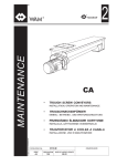
TROUGH SCREW CONVEYORS
INSTALLATION, OPERATION AND MAINTENANCE
•
TROGSCHNECKENFÖRDERER
EINBAU-, BETRIEBS-, UND WARTUNGSANLEITUNG
•
TRANSPORTEURS A VIS EN AUGE
INSTALLATION, UTILISATION ET ENTRETIEN
•
TRASPORTATORI A COCLEA A CANALA
All rights reserved © WAMGROUP
INSTALLAZIONE, USO E MANUTENZIONE
CATALOGUE No.
WA.01010.M
CREATION DATE
ISSUE
CIRCULATION
DATE OF LATEST UPDATE
A8
100
05.07
11 - 2000
All the products described in this catalogue are manufactured according to WAM ® S.p.A. Quality System
procedures.
The Company’s Quality System, certified in July 1994 according to International Standards UNI EN ISO 9002-94 and
extended to UNI EN ISO 9001-2000 in October, 2002, ensures that the entire production process, starting from the
processing of the order to the technical service after delivery, is carried out in a controlled manner that guarantees
the quality standard of the product.
Alle in diesem Katalog beschriebenen Erzeugnisse werden in Konformität mit dem Qualitätssystem der WAM®
S.p.A. hergestellt.
Das im Juli 1994 zertifizierte Qualitätssystem entspricht der Norm UNI EN ISO 9002-94 (im Oktober 2002 auf
UNI EN ISO 9001-2000 erweitert) und gewährleistet dem Kunden eine strenge Qualitätskontrolle in jeder Phase
des Produktionprozesses bis hin zum Kundendienst nach Auslieferung der Ware.
Tous les produits décrits dans ce catalogue ont été réalisé selon les modalités opérationnelles définies Système
de Qualité de WAM® S.p.A.
Le système de Qualité de l’entreprise, certifié au mois de juillet 1994 en conformité aux Normes Internationales UNI
EN ISO 9002-94 et successivement étendu à UNI EN ISO 9001-2000 au mois de octobre 2002, est en mesure
d’assurer que le procédé entier de production, à partir de la formulation de la commande jusqu’au service technique
après la livraison, soit effectué de manière contrôlée et appropriée afin de garantir le standard de qualité du produit.
Tutti i prodotti descritti in questo catalogo sono stati realizzati secondo modalità operative definite Sistema
Qualità di WAM ® S.p.A.
Il Sistema Qualità aziendale, certificato dal luglio 1994 in conformità alle Normative Internazionali UNI EN ISO
9002-94 e successivamente esteso alle Normative Internazionali UNI EN ISO 9001-2000 nell’ottobre 2002, è in
grado di assicurare che l’intero processo produttivo, dalla formulazione dell’ordine fino all’assistenza tecnica
successiva alla consegna, venga effettuato in modo controllato ed adeguato a garantire lo standard qualitativo
del prodotto.
UNI EN ISO 9001-2000
Certified Company
This publication cancels and replaces any previous edition and revision.
We reserve the right to implement midifications without notice.
This catalogue cannot be reproduced, even partially, without prior consent.
Diese Veröffentlichung annuliert und ersetzt jeder hergehende Edition oder Revision.
WAM ® behält sich das Recht vor, Anderungen ohne vorherige Informationen durchzuführen.
Cette publication annule et remplace toutes les autres précédentes.
Nous nous réservons le droit d’apporter toutes modifications à nos produits.
La reproduction et la publication partielle ou totale de ce catalogue est interdite sans notre autorisation.
Questa pubblicazione annulla e sostituisce ogni precedente edizione o revisione.
Ci riserviamo il diritto di apportare modifiche senza preavviso.
E’ vietata la riproduzione anche parziale senza autorizzazione.
05.07
- INDEX
CA
(CMC)
- INHALTSVERZEICHNIS
- INDEX
- INDICE
1
WA.01010.INDEX
1 TECHNISCHER KATALOG
TECHNICAL CATALOGUE
CODE INDEX.....................................................................................................................
INTRODUCTION ABBREVIATED CODE.........................................................................
STANDARD SUPPLY..........................................................................................................
ACCESSORIES..................................................................................................................
OVERALL DIMENSION CA _ _AN-TYPE.........................................................................
MECHANICAL COMPONENTS CA_LN - CA_PN - CA_EN..........................................
MECHANICAL COMPONENTS CS_L- CS_P - CS_E....................................................
DIRECT DRIVE (S-TYPE GEAR REDUCER).................................................................
CA_LN FABRICATED COMPONENTS............................................................................
CA_PN STRUCTURAL COMPONENTS.........................................................................
CA_EN STRUCTURAL COMPONENTS.........................................................................
CS SCREW FEEDER FABRICATED PARTS...................................................................
FINISHING..........................................................................................................................
COLOURS...........................................................................................................................
MODULAR CODE KEY......................................................................................................
INQUIRY FORM................................................................................................................
U - SECTION TROUGH ...................................................................................................
END PLATE XPU - TYPE ..................................................................................................
V - SECTION (FLARED) TROUGH..................................................................................
END PLATE XPV - TYPE...................................................................................................
SCREW...............................................................................................................................
TROUGH COVER..............................................................................................................
COVER LOCK.....................................................................................................................
END BEARING ASSEMBLIES TYPE XSA - XSB - XSK...................................................
END BEARING ASSEMBLY TYPE - XSP..........................................................................
END BEARING ASSEMBLY TYPE - XSR.........................................................................
SHAFT SEALING TYPE - XUC.........................................................................................
HANGER BEARING TYPE - XLB .....................................................................................
HANGER BEARING TYPE - XLM......................................................................................
HANGER BEARING TYPE - XLN......................................................................................
HANGER BEARING TYPE - XLP......................................................................................
HANGER BEARING TYPE - XLG......................................................................................
SHAFT COUPLINGS XAA and XAC..................................................................................
SHAFT COUPLING XAV.....................................................................................................
CUT FLIGHT SCREW........................................................................................................
PADDLE SCREW-RIBBON SCREW.................................................................................
GEAR REDUCER - TYPE S 21-23-25-27.........................................................................
MOTOR MT.........................................................................................................................
OPTIONS - BELT TRANSMISSION (“S”-TYPE GEAR REDUCER)..............................
OPTIONS - CHAIN TRANSMISSION (“S”-TYPE GEAR REDUCER)...........................
MOUNT V-TROUGH SCREW (100-120) WAM® REDUCER.........................................
MOUNT V-TROUGH SCREW, POS. SOUTH WAM® REDUCER................................
OPTIONS - COUPLING TRANSMISSION (“S”-TYPE GEAR REDUCER)...................
OPTIONS - XSQ END BEARING ASSEMBLY..................................................................
OPTIONS - XSS END BEARING ASSEMBLY...................................................................
OPTIONS - XLN INTERMEDIATE BEARING...................................................................
ACCESSORIES - XBQ TYPE SQUARE INLET................................................................
ACCESSORIES - XBV TYPE RECTANGULAR INLET....................................................
ACCESSORIES - XBR TYPE RECTANGULAR INLET....................................................
ACCESSORIES - XBV TYPE RECTANGULAR OUTLET....................................................
ACCESSORIES - XBR TYPE RECTANGULAR OUTLET....................................................
ACCESSORIES - XBQ TYPE ADDITIONAL SQUARE OUTLET....................................
ACCESSORIES - XBV TYPE ADDITIONAL RECTANGULAR OUTLET.........................
ACCESSORIES - XBR TYPE ADDITIONAL RECTANGULAR OUTLET........................
OPTIONS - XBW-TYPE FLUSH OUTLET.........................................................................
ACCESSORIES - CYLINDRICAL INLET XBC.................................................................
OPTIONS - CYLINDRICAL OUTLET XBC.......................................................................
ACCESSORIES - ROTATIONAL INDICATOR BRACKET XVA.......................................
ACCESSORIES - HIGH SIDE TROUGH CHANNELS....................................................
ACCESSORIES - HIGH END PLATE................................................................................
ACCESSORIES - XFBA - TYPE OVERFLOW HATCH FLAP..........................................
ACCESSORIES - XKX - TYPE FINGER MESH BENEATH HATCH FLAP.....................
ACCESSORIES - MEMBRANE HATCH XKYU...............................................................
ACCESSORIES - XJQ - TYPE COVER SUPPORT BRACKET.......................................
ACCESSORIES - SEPARATING DIAPHGRAM XJV.........................................................
ACCESSORIES - FLOW STOPPING DIAPHRAGM XJE................................................
ACCESSORIES - TUBULAR INSERT XJG......................................................................
ACCESSORIES - TROUGH FOOT TYPE XJS................................................................
ACCESSORIES - COPERCHIO INCERNIERATO...........................................................
OPTIONS - XJZ CLAMP LOCK - XKM - TYPE SCREW LAMP.....................................
ADDITIONAL INTERNAL SEAL.......................................................................................
OPTIONS - DROP BOTTOM TROUGH (TROUGH WITHOUT OUTLET)...................
OPTIONS - DROP BOTTOM TROUGH (TROUGH WITH OUTLET XBQ)..................
OPTIONS - DROP BOTTOM TROUGH (TROUGH WITH OUTLET XBV)...................
OPTIONS - DROP BOTTOM TROUGH (TROUGH WITH OUTLET XBR)..................
OPTIONS - DROP BOTTOM TROUGH (TROUGH WITH OUTLET XBW).................
TROUGH CONFIGURATION Ø 100 - 250........................................................................
TROUGH CONFIGURATION Ø 300 - 600........................................................................
SHIPPING DATA Ø 100 - 250.............................................................................................
SHIPPING DATA Ø 300 - 600.............................................................................................
WEIGHTS CA_L AN..........................................................................................................
WEIGHTS CA_P AN.........................................................................................................
WEIGHTS CA_E AN.........................................................................................................
CODES UND SUCHCODES......................................................................................... T.
EINFÜHRUNG ABGEKÜRZTER.................................................................................... “
STANDARD-LIEFERUMFANG........................................................................................ “
ZUBEHÖR.......................................................................................................................... “
EINBAUMASSE TYP CA _ _AN....................................................................................... “
MECHANISCHE KOMPONENTEN CA_LN / CA_PN / CA_EN................................ “
MECHANISCHE KOMPONENTEN CS_L / CS_P / CS_E.......................................... “
DIREKTANTRIEB (S-GETRIEBE)................................................................................... “
STAHLBAUTEILE CA_LN................................................................................................. “
STAHLBAUTEILE CA_PN........................................................................................... “
STAHLBAUTEILE CA_EN........................................................................................... “
STAHLBAU SCHNECKEN CS......................................................................................... “
FINISH................................................................................................................................. “
FARBTÖNE........................................................................................................................ “
SUCHCODESCHLÜSSEL................................................................................................ “
ANFRAGEFORMULAR.................................................................................................... “
U - TROG............................................................................................................................ “
ENDSCHILD XPU.............................................................................................................. “
V - TROG............................................................................................................................. “
ENDSCHILD XPV............................................................................................................... “
SCHNECKENWENDEL.................................................................................................... “
TROGABDECKUNG.......................................................................................................... “
ABDECKUNGSVERSCHLUSS........................................................................................ “
ENDLAGEREINHEITEN XSA - XSB - XSK................................................................... “
ENDLAGEREINHEIT XSP................................................................................................. “
ENDLAGEREINHEIT XSR.......................................................................................... “
WELLENABDICHTUNG TYP XUC.................................................................................. “
ZWISCHENLAGER XLB.................................................................................................... “
ZWISCHENLAGER XLM................................................................................................... “
ZWISCHENLAGER XLN................................................................................................... “
ZWISCHENLAGER XLP.................................................................................................... “
ZWISCHENLAGER XLG.................................................................................................... “
WELLENVERBINDUNGEN XAA und XAC...................................................................... “
WELLENVERBINDUNG XAV............................................................................................ “
STOLLENWENDEL............................................................................................................ “
PADDELWENDEL-BANDWENDEL.................................................................................. “
GETRIEBE TYP S 21-23-25-27......................................................................................... “
MOTOR MT........................................................................................................................ “
VARIANTEN - RIEMENTRIEB (GETRIEBE TYP “S”)................................................... “
VARIANTEN - KETTENTRIEB (GETRIEBE TYP “S”).................................................. “
KONSOLE V-TROGSCHNECKEN (100-120)WAM®GETRIEBE................................. “
KONSOLE V-TROGSCHNECKEN POS. SÜD WAM®GETRIEBE.............................. “
VARIANTEN - KUPPLUNG (GETRIEBE TYP “S”)........................................................ “
VARIANTEN - ENDLAGEREINHEIT TYP XSQ.............................................................. “
VARIANTEN - ENDLAGEREINHEIT TYP XSS.............................................................. “
VARIANTEN - ZWISCHENTRÄGER XLN...................................................................... “
ZUBEHÖR - QUADRATISCHER EINLAUF TYP XBQ.................................................. “
ZUBEHÖR - RECHTECK - EINLAUF TYP XBV............................................................ “
ZUBEHÖR - RECHTECK - EINLAUF TYP XBR........................................................... “
ZUBEHÖR - RECHTECK - AUSLAUF TYP XBV............................................................“
ZUBEHÖR - RECHTECK - AUSLAUF TYP XBR...........................................................“
ZUBEHÖR - ZUSÄTZLICHER QUADRATISCHER AUSLAUF TYP XBQ................. “
ZUBEHÖR - ZUSÄTZLICHER RECHTECK - AUSLAUF TYP XBV............................ “
ZUBEHÖR - ZUSÄTZLICHER RECHTECK - AUSLAUF TYP XBR........................... “
VARIANTEN - FRONTALAUSLAUF XBW....................................................................... “
ZUBEHÖR - ZYLINDRISCHER EINLAUF XBC............................................................ “
VARIANTEN - ZYLINDRISCHER AUSLAUF XBC........................................................ “
ZUBEHÖR - SOCKEL FÜR ROTATIONSMELDER XVA.............................................. “
ZUBEHÖR - ERHÖHTE TROGFLANKEN..................................................................... “
ZUBEHÖR - ERHÖHTER ENDSCHILD........................................................................ “
ZUBEHÖR - ÜBERLAUFKLAPPE TYP XFBA................................................................ “
ZUBEHÖR - SCHUTZGITTER TYP XKX UNTER ÜBERLAUFKLAPPE................... “
ZUBEHÖR - MEMBRANKLAPPE XHYU........................................................................ “
ZUBEHÖR - ABDECKUNGSAUFLAGEBÜGEL TYP XJQ........................................... “
ZUBEHÖR - TRENNWEHR XJV..................................................................................... “
ZUBEHÖR - DURCHFLUSSSPERRE XJE................................................................... “
ZUBEHÖR - VERDRÄNGUNGSELEMENT XJG.......................................................... “
ZUBEHÖR - TROGFUSS TYP XJS................................................................................ “
ZUBEHÖR - COPERCHIO INCERNIERATO................................................................. “
VARIANTEN - SPANNVERSCHL. XJZ SCHRAUBZWINGENVERSCHL. XKM.......... “
ZUSÄTZLICHE INNENDICHTUNG................................................................................ “
VARIANTEN - ABKLAPP. TROGBODEN (TROG OHNE STUTZEN)....................... “
VARIANTEN - ABKLAPP. TROGBODEN (TROG MIT XBQ-AUSLAUF).................... “
VARIANTEN - ABKLAPP. TROGBODEN (TROG MIT XBV-AUSLAUF)..................... “
VARIANTEN - ABKLAPP. TROGBODEN (TROG MIT XBR-AUSLAUF).................... “
VARIANTEN - ABKLAPP. TROGBODEN (TROG MIT XBW-AUSLAUF)................... “
TROGKONFIGURATION Ø 100 - 250............................................................................. “
TROGKONFIGURATION Ø 300 - 600............................................................................. “
KOLLIDATEN Ø 100 - 250................................................................................................. “
KOLLIDATEN Ø 300 - 600.................................................................................................. “
GEWICHTE CA_L AN...................................................................................................... “
GEWICHTE CA_P AN................................................................................................ “
GEWICHTE CA_E AN................................................................................................ “
.5
.6
.7
.8
.9
. 10
. 11
. 12
. 13
. 14
. 15
. 16
. 17
. 18
. 19 →. 21
. 22 →. 25
. 26
. 27
. 28
. 29
. 30
. 31
. 32
. 33
. 34
. 35
. 36
. 37
. 38
. 39
. 40
. 41
. 42
. 43
. 44
. 45
. 46 →. 47
. 48 →. 49
. 50
. 51
. 52
. 53
. 54
. 55
. 56
. 57
. 58
. 59
. 60
. 61
. 62
. 63
. 64
. 65
. 66
. 67
. 68
. 69
. 70
. 71
. 72
. 73
. 74
. 75
. 76
. 77
. 78
. 79
. 80
. 81
. 82
. 83
. 84
. 85
. 86
. 87
. 88
. 89
. 90
. 91
. 92
. 93
. 94
CATALOGUE
2 MAINTENANCE
2 WARTUNGSKATALOG
OPERATION AND MAINTENANCE.................................................................................
BETRIEBS- UND WARTUNGSANLEITUNG..................................................................M . 5 →. 25
PARTS CATALOGUE
3 SPARE
3 ERSATZEILKATALOG
SPARE PARTS............................................................................................................................ ERSATZEILKATALOG.........................................................................................................R
SPARE PARTS - XSP-XSR END BEARING ..........................................................................
SPARE PARTS - XSA-XSB-XSK END BEARING .................................................................
SPARE PARTS - XUC SHAFT SEALING .................................................................................
SPARE PARTS - XLP HANGER BEARING ............................................................................
SPARE PARTS - XLG HANGER BEARING.............................................................................
SPARE PARTS - XLM HANGER BEARING............................................................................
SPARE PARTS - XLB HANGER BEARING.............................................................................
SPARE PARTS - XLL HANGER BEARING..............................................................................
SPARE PARTS............................................................................................................................
ERSATZEILKATALOG - ENDLAGEREINHEIT XSP-XSR...............................................
ERSATZEILKATALOG - ENDLAGEREINHEIT XSA-XSB-XSK .....................................
ERSATZEILKATALOG - WELLENABDICHTUNG XUC ................................................
ERSATZEILKATALOG - ZWISCHENLAGER XLP ..........................................................
ERSATZEILKATALOG - XLG HANGER BEARING..........................................................
ERSATZEILKATALOG - XLM HANGER BEARING..........................................................
ERSATZEILKATALOG - XLB HANGER BEARING...........................................................
ERSATZEILKATALOG - XLL HANGER BEARING...........................................................
ERSATZEILKATALOG.........................................................................................................
.5→. 7
. 8 →. 12
.13 →. 15
.16 →. 20
. 21 →. 24
. 25 →. 27
. 28 →. 29
. 30 →. 33
. 34 →. 35
. 36 →. 62
05.07
- INDEX
CA
(CMC)
- INHALTSVERZEICHNIS
- INDEX
WA.01010.INDEX
- INDICE
1 CATALOGUE TECHNIQUE
CODES ET SIGLES..............................................................................................................
INTRODUCTION CODE ABRÉGÉE..................................................................................
COMPOSITION STANDARD..............................................................................................
ACCESSOIRES.....................................................................................................................
ENCOMBREMENT TYPE CA _ _AN..................................................................................
COMPOSANTS MECANIQUES CA_LN - CA_PN - CA_EN.............................................
COMPOSANTS MECANIQUES CS_L - CS_P - CS_E.....................................................
ENTRAINEMENT DIRECTE (REDUCTEUR TYPE “S”).................................................
COMPOSANTS STRUCTURE CA_LN..............................................................................
COMPOSANTS STRUCTURE CA_PN..............................................................................
COMPOSANTS STRUCTURE CA_EN..............................................................................
CHARPENTE VIS CS...........................................................................................................
FINITION...............................................................................................................................
TONALITES...........................................................................................................................
CODE MODULAIRE TYP CA..............................................................................................
FICHE DE DOMANDE.........................................................................................................
AUGE SECTION “U” ...........................................................................................................
FLASQUE COTE XPU..........................................................................................................
AUGE SECTION “V”.............................................................................................................
FLASQUE COTE XPV...........................................................................................................
SPIRE....................................................................................................................................
CAPOTAGE...........................................................................................................................
FERMETURE CAPOTAGE..................................................................................................
SUPPORTS PALIERS D’EXTREMITE TYPE XSA - XSB - XSK........................................
SUPPORT PALIER D’EXTREMITE TYPE XSP..................................................................
SUPPORT PALIER D’EXTREMITE TYPE XSR..................................................................
ETANCHEITE TYP XUC......................................................................................................
SUPPORT PALIER INTERMEDIAIRE XLB.........................................................................
SUPPORT PALIER INTERMEDIAIRE XLM........................................................................
SUPPORT PALIER INTERMEDIAIRE XLN.........................................................................
SUPPORT PALIER INTERMEDIAIRE XLP.........................................................................
SUPPORT PALIER INTERMEDIAIRE XLG.........................................................................
ACCOUPLEMENTS XAA et XAC........................................................................................
ACCOUPLEMENT XAV........................................................................................................
SPIRE DÉCOUPÉE..............................................................................................................
SPIRE A PALETTES-SPIRE A RUBAN...............................................................................
REDUCTEUR TYPE S 21-23-25-27...................................................................................
MOTEUR MT........................................................................................................................
OPTIONS - ENTRAINEMENT PAR COURROIES (REDUCTEUR TYPE “S”)...............
OPTIONS - ENTRAINEMENT PAR CHAINE (REDUCTEUR TYPE “S”).......................
BÂTI VIS EN AUGE V(100-120) RÉDUCTEURS WAM®...................................................
BÂTI VIS EN AUGE V POS. SUD RÉDUCTEURS WAM®................................................
OPTIONS - ENTRAINEM. AV.ACCOUPL.DEMI-ELASTIQUE (RED.TYPE “S”).............
OPTIONS - SUPPORT PALIER D’EXTREMITE TYPE XSQ.............................................
OPTIONS - SUPPORT PALIER D’EXTREMITE TYPE XSS.............................................
OPTIONS - PALIER INTERMÉDIAIRE XLN....................................................................
ACCESSOIRES - BOUCHE D’ENTREE CARREE XBQ..................................................
ACCESSOIRES - BOUCHE D’ENTREE RECTANGULAIRE XBV...................................
ACCESSOIRES - BOUCHE D’ENTREE RECTANGULAIRE XBR..................................
ACCESSOIRES - DECHARGE RECTANGULAIRE XBV..................................................
ACCESSOIRES - DECHARGE RECTANGULAIRE XBR.................................................
ACCESSOIRES - DECHARGE CARREE ADDITIONNELLE XBQ..................................
ACCESSOIRES - DECHARGE RECTANGULAIRE ADDITIONNELLE XBV...................
ACCESSOIRES - DECHARGE RECTANGULAIRE ADDITIONNELLE XBR..................
OPTIONS - BOUCHE DE DECHARGE XBW....................................................................
ACCESSOIRES - BOUCHE DE CHARGE CYLINDRIQUE XBC.....................................
OPTIONS - BOUCHE DECHARGE CYLINDRIQUE XBC................................................
ACCESSOIRES - BASE POUR AVERTISSEUR DE ROTATION XVA..............................
ACCESSOIRES - REHAUSSE D’AUGE.............................................................................
ACCESSOIRES - REHAUSSE DE FLASQUE...................................................................
ACCESSOIRES - CAPOT MOBILE XFBA..........................................................................
ACCESSOIRES - GRILLE SOUS CAPOT MOBILE XKX...................................................
ACCESSOIRES - TRAPPE A MEMBRANE XKYU............................................................
ACCESSOIRES - SUPPORT CAPOT XJQ........................................................................
ACCESSOIRES - DIAPHRAGME DE DIVISION XJV........................................................
ACCESSOIRES - DIAPHRAGME ARRET DE FLUX XJE................................................
ACCESSOIRES - INSERT TUBULAIRE XJG.....................................................................
ACCESSOIRES - SEMELLE SUPPORT XJS.....................................................................
ACCESSOIRES - COUVERCLE INCERNIERATO............................................................
OPTIONS - SERRE-JOINTS A RUBAN XJZ - PINCE A VIS XKM...................................
ETANCHEITE INTERNE ADDITIONNELLE......................................................................
OPTIONS - FOND OUVRABLE (AUGE SANS BOUCHE)................................................
OPTIONS - FOND OUVRABLE (AUGE AVEC BOUCHE XBQ).......................................
OPTIONS - FOND OUVRABLE (AUGE AVEC BOUCHE XBV)........................................
OPTIONS - FOND OUVRABLE (AUGE AVEC BOUCHE XBR)........................................
OPTIONS - FOND OUVRABLE (AUGE AVEC BOUCHE XBW).......................................
DISPOSITION CONSTRUCTIVE Ø 100 / 250.....................................................................
DISPOSITION CONSTRUCTIVE Ø 300 / 600.....................................................................
COLISAGE Ø 100 / 250.........................................................................................................
COLISAGE Ø 300 / 600.........................................................................................................
POIDS CA_L AN...................................................................................................................
POIDS CA_P AN...................................................................................................................
POIDS CA_E AN...................................................................................................................
2
CATALOGUE D’ENTRETIEN
UTILISATION ET ENTRETIEN...........................................................................................
PIECES DE RECHANGE
3 CATALOGUE
PIECES DE RECHANGE...........................................................................................................
PIECES DE RECHANGE - SUPPORT D’EXTREMITE XSP-XSR ......................................
PIECES DE RECHANGE - SUPPORT D’EXTREMITE XSA-XSB-XSK .............................
PIECES DE RECHANGE - ETANCHEITE XUC.................................. ..................................
PIECES DE RECHANGE - SUPPORT PALIER INTERMEDIAIRE XLP...............................
PIECES DE RECHANGE - SUPPORTO INTERMEDIO XLG...............................................
PIECES DE RECHANGE- SUPPORTO INTERMEDIO XLM...............................................
PIECES DE RECHANGE - SUPPORTO INTERMEDIO XLB...............................................
PIECES DE RECHANGE - SUPPORTO INTERMEDIO XLL................................................
PIECES DE RECHANGE...........................................................................................................
1 CATALOGO TECNICO
CODICI E SIGLE....................................................................................................... T.
INTRODUZIONE CODICE ABBREVIATO............................................................. “
FORNITURA STANDARD....................................................................................... “
ACCESSORI............................................................................................................... “
INGOMBRI COCLEA TIPO CA_ _AN..................................................................... “
COMPONENTI MECCANICA CA_LN - CA_PN - CA_EN................................. “
COMPONENTI MECCANICA CS_L - CS_P - CS_E.......................................... “
MOTORIZZAZIONE DIRETTA (TESTATA MOTRICE TIPO “S”)........................ “
COMPONENTI CARPENTERIA CA_LN............................................................... “
COMPONENTI CARPENTERIA CA_PN........................................................... “
COMPONENTI CARPENTERIA CA_EN........................................................... “
CARPENTERIA COCLEE CS............................................................................ “
FINITURA.................................................................................................................. “
TONALITÀ.................................................................................................................. “
CHIAVE SIGLA MODULARE TIPO CA................................................................... “
MODULO RICHIESTA.............................................................................................. “
TRUOGOLO AD “U”................................................................................................. “
PORTASUPPORTO XPU......................................................................................... “
TRUOGOLO A “V”..................................................................................................... “
PORTASUPPORTO XPV.......................................................................................... “
SPIRA......................................................................................................................... “
COPERCHIO............................................................................................................. “
CHIUSURA COPERCHIO....................................................................................... “
SUPPORTI D’ESTREMITÁ XSA - XSB - XSK...................................................... “
SUPPORTO D’ESTREMITÁ XSP....................................................................... “
SUPPORTO D’ESTREMITÁ XSR...................................................................... “
TENUTA XUC........................................................................................................... “
SUPPORTO INTERMEDIO XLB............................................................................. “
SUPPORTO INTERMEDIO XLM............................................................................ “
SUPPORTO INTERMEDIO XLN............................................................................. “
SUPPORTO INTERMEDIO XLP.............................................................................. “
SUPPORTO INTERMEDIO XLG............................................................................. “
ACCOPPIAMENTI XAA e XAC................................................................................ “
ACCOPPIAMENTO XAV.......................................................................................... “
ELICA TAGLIATA........................................................................................................ “
ELICA A PALETTE-ELICA A NASTRO................................................................... “
TESTATA MOTRICE S 21-23-25-27......................................................................... “
MOTORE MT............................................................................................................. “
OPZIONI - TRASMISSIONE A CINGHIE (TEST.MOTR.TIPO “S”).................... “
OPZIONI - TRASMISSIONE A CATENA (TEST.MOTR.TIPO “S”)..................... “
BASAMENTO COCLEE CANALA V(100-120)RIDUTTORI WAM®.................... “
BASAMENTO COCLEE CANALA V POSIZIONE SUD RIDUTTORI WAM®.... “
OPZIONI - TRASMISSIONE CON GIUNTO (TEST.MOTR.TIPO “S”).............. “
OPZIONI - SUPPORTO D’ESTREMITÁ XSQ....................................................... “
OPZIONI - SUPPORTO D’ESTREMITÁ XSS........................................................ “
OPZIONI - SUPPORTO INTERMEDIO XLN......................................................... “
ACCESSORI - BOCCA CARICO QUADRATA XBQ............................................. “
ACCESSORI - BOCCA CARICO RETTANGOLARE XBV................................... “
ACCESSORI - BOCCA CARICO RETTANGOLARE XBR................................... “
ACCESSORI - BOCCA SCARICO RETTANGOLARE XBV.................................. “
ACCESSORI - BOCCA SCARICO RETTANGOLARE XBR................................. “
ACCESSORI - BOCCA SCARICO QUADRATA SUPPL. XBQ............................ “
ACCESSORI - BOCCA SCARICO RETTANGOLARE SUPPL. XBV................... “
ACCESSORI - BOCCA SCARICO RETTANGOLARE SUPPL. XBR.................. “
OPZIONI - BOCCA SCARICO XBW....................................................................... “
ACCESSORI - BOCCA CARICO CILINDRICA XBC.......................................... “
OPZIONI - BOCCA SCARICO XBC....................................................................... “
ACCESSORI - BASETTA PER RILEVATORE DI ROTAZIONE XVA................... “
ACCESSORI - SPONDE RIALZATE....................................................................... “
ACCESSORI - PORTASUPPORTO DI RIALZO................................................... “
ACCESSORI - PORTELLO ANTINTASAMENTO XFBA...................................... “
ACCESSORI - RETE SOTTO PORTELLO XKX................................................... “
ACCESSORI - PORTELLO A MEMBRANA XKYU............................................... “
ACCESSORI - SOTTOCOPERCHIO XJQ............................................................. “
ACCESSORI - DIAFRAMMA DIVISORIO XJV...................................................... “
ACCESSORI - DIAFRAMMA FERMAFLUSSO XJE............................................ “
ACCESSORI - INSERTO TUBOLARE XJG........................................................... “
ACCESSORI - SELLA XJS....................................................................................... “
ACCESSORI - COPERCHIO INCERNIERATO.................................................... “
OPZIONI - MORSETTO A FASCIA XJZ - MORSETTO A VITE XKM................ “
TENUTA ADDIZIONALE INTERNA........................................................................ “
OPZIONI - FONDO APRIBILE (TRUOGOLO SENZA BOCCA).......................... “
OPZIONI - FONDO APRIBILE (TRUOGOLO CON BOCCA XBQ).................... “
OPZIONI - FONDO APRIBILE (TRUOGOLO CON BOCCA XBV)..................... “
OPZIONI - FONDO APRIBILE (TRUOGOLO CON BOCCA XBR)..................... “
OPZIONI - FONDO APRIBILE (TRUOGOLO CON BOCCA XBW).................... “
DISPOSIZIONE TRUOGOLI Ø 100 / 250................................................................ “
DISPOSIZIONE TRUOGOLI Ø 300 / 600................................................................ “
INGOMBRI SPEDIZIONE Ø 100 / 250..................................................................... “
INGOMBRI SPEDIZIONE Ø 300 / 600..................................................................... “
PESI CA_L AN............................................................................................................ “
PESI CA_P AN........................................................................................................... “
PESI CA_E AN........................................................................................................... “
.5
.6
.7
.8
.9
. 10
. 11
. 12
. 13
. 14
. 15
. 16
. 17
. 18
. 19 →. 21
. 22 →. 25
. 26
. 27
. 28
. 29
. 30
. 31
. 32
. 33
. 34
. 35
. 36
. 37
. 38
. 39
. 40
. 41
. 42
. 43
. 44
. 45
. 46 →. 47
. 48 →. 49
. 50
. 51
. 52
. 53
. 54
. 55
. 56
. 57
. 58
. 59
. 60
. 61
. 62
. 63
. 64
. 65
. 66
. 67
. 68
. 69
. 70
. 71
. 72
. 73
. 74
. 75
. 76
. 77
. 78
. 79
. 80
. 81
. 82
. 83
. 84
. 85
. 86
. 87
. 88
. 89
. 90
. 91
. 92
. 93
. 94
CATALOGO DI MANUTENZIONE
USO E MANUTENZIONE........................................................................................ M . 5 →. 25
CATALOGO RICAMBI
PEZZI DI RICAMBIO................................................................................................ R .5→. 7
. 8 →. 12
PEZZI DI RICAMBIO - SUPPORTO D’ESTREMITÀ XSP-XSR............................
.13 →. 15
PEZZI DI RICAMBIO - SUPPORTO D’ESTREMITÀ XSA-XSB-XSK......................
.16 →. 20
PEZZI DI RICAMBIO - TENUTA XUC.....................................................................
. 21 →. 24
PEZZI DI RICAMBIO - SUPPORTO INTERMEDIO XLP............................................
. 25 →. 27
PEZZI DI RICAMBIO - SUPPORTO INTERMEDIO XLG............................................
. 28 →. 29
PEZZI DI RICAMBIO - SUPPORTO INTERMEDIO XLM............................................
. 30 →. 33
PEZZI DI RICAMBIO - SUPPORTO INTERMEDIO XLB............................................
. 34 →. 35
PEZZI DI RICAMBIO - SUPPORTO INTERMEDIO XLL...........................................
. 36 →. 62
PEZZI DI RICAMBIO................................................................................................
05.07
- OPERATION AND MAINTENANCE
- BETRIEBS- UND WARTUNGSANLEITUNG
CA
(CMC)
2
- UTILISATION ET ENTRETIEN
- USO E MANUTENZIONE
WA.01010.M. 5
ADDRESS OF LOCAL DEALER OR
LOCAL SERVICE POINT
ADRESSE DES HÄNDLERS ODER ADRESSE DU REVENDEUR OU DU INDIRIZZO RIVENDITORE O
DES KUNDENDIENSTES VOR ORT SERVICE APRES-VENTE LOCAL
PUNTO DI ASSISTENZA LOCALE
IDENTIFICATION
OF THE EQUIPMENT
INTERPRETATION
DES TYPENSCHILDES
INTERPRETATION
DE LA PLAQUE
INTERPRETAZIONE
DELLA TARGHETTA
For a correct identification of the
equipment please refer to the code
number shown on the acknowledgement of order, on the invoice and on
the equipment itself.
Zur eindeutigen Identifikation der
Schnecke ist auf die Seriennummer
Bezug zu nehmen. Diese befindet sich
in der Auftragsbestätigung, in der
Rechnung und auf dem Typenschild
der Schnecke.
Pour l’identification correcte de la
machine il faut se référer au numéro
de matricule qui se trouve sur la confirmation de commande, sur la facture et sur la plaque de la machinemême.
Per una corretta identificazione della
macchina, bisogna fare riferimento
al numero di matricola che si trova
sulla conferma d'ordine, sulla fattura
e sulla targhetta posta sulla macchina stessa.
1) Code de la machine.
2) Sigle numéro de matricule machine.
CONTREINDICATIONS
A L’UTILISATION
Il n’y a aucune contreindication à
l’utilisation si les précautions normales pour machines de ce type
sont observées ensemble aux indications contenues dans ce catalogue.
1) Codice macchina.
2) Sigla matricolare macchina.
CES MACHINES NE SONT PAS INDIQUÉES POUR LE TRANSPORT
DE PRODUITS ALIMENTAIRES
En outre il est interdit de les mettre
en fonction avant que la machine/
l’installation dans laquelle elles
doivent être montées a été déclarée conforme aux dispositions de
la Directive 14/06/1982 (89/392/
EEC).
Dans ce cadre il est la responsabilité du constructeur de l’installation
ou de l’installateur de projeter et
d’installer tout équipement de protection nécessaire afin d’eviter que
des ruptures et/ou des parties d’elle puissent causer de dégâts à des
personnes et/ou des choses (par
ex.: des protections appropriées
contre la chaute du moteur,...).
L’installateur doit prévoir des dispositifs protectifs appropriés pour
la manutention de produits avec les
caractéristiques suivantes: nocif au
contact et/ou à l’inhalation, inflammable, explosif, infectieux.
Compte tenu de la similitude structurelle générale des composants
les plus importants et des modalités avec lesquelles effectuer toutes les opérations prévues dans le
manuel d’utilisation et d’entretien,
le présent catalogue doit, à tous
les effets, être considéré valable
et applicable même pour la machine où est apposée la plaque signalétique portant le sigle CMC.
QUESTE MACCHINE NON SONO IDONEE AL TRASPORTO DI PRODOTTI
ALIMENTARI
E’ inoltre vietato metterle in funzione
prima che la macchina/impianto nel
quale devono essere installate sia dichiarato conforme alle disposizioni
della direttiva 14/06/1982 (89/392/
EEC). In quest’ambito è cura dell’impiantista/installatore predisporre ed installare tutti gli accorgimenti/protezioni al fine di evitare danni a cose e/
o persone in caso di rotture e conseguente caduta di pezzi della macchina (ad es.: rottura del motore,...).
Per prodotti pericolosi, nocivi al contatto e/o all’inalazione, infiammabili, esplosivi e pericolosi dal punto
di vista batteriologico e/o virale, l’impiantista e/o l’installatore dovranno
prevedere idonei dispositivi all’uso.
1
2
1) Machine code.
2) Machine registration code.
1) Gerätecode
2) Geräte-Serien-Nr.
CONTRA-INDICATIONS
If the customer follows normal precautions for this type of equipment
together with the instructions given
in this manual, operation is safe.
KONTRAINDIKATIONEN ZUR BENUTZUNG
Es bestehen keine Kontraindikationen zur Benutzung, sofern die allgemein üblichen Vorsichtsmaßnahmen für Geräte dieser Art sowie die in dieser Dokumentation
enthaltenen, speziellen Vorschriften befolgt werden.
DIESE MASCHINEN EIGNEN SICH
NICHT ZUR NAHRUNGSMITTELBEFÖRDERUNG
Das Gerät darf nicht in Betrieb genommen werden, bevor sowohl es
selbst, als auch die Anlage, in die
es eingebaut wird, mit den Vorschriften der Direktive 14/06/1982
(89/392/EEC) für konform erklärt
wurde. Es liegt in der Verantwortung
des Anlagenplaners bzw. -aufstellers,
alle notwendigen Schutzvorrichtungen vorzusehen, welche es verhindern, daß durch einen Geräteoder Teiledefekt Personen- und/
oder Sachschäden verursacht werden (z.B. geeigneter Schutz gegen
das Herunterfallen des Motors,...).
Zum Handling von Medien mit den
folgenden Charakteristiken muß
der Anlagenbauer bzw. -aufsteller
geeignete Schutzmaßnahmen treffen: gefährlich, schädlich wenn in
Körperkontakt oder wenn eingeatmet, feuergefährlich, explosiv, infektionsgefährlich.
Aufgrund der Ähnlichkeit ihrer allgemeinen Bestandteile und der Art
und Weise, in der alle in der Betriebs- und Wartungsanleitung
vorgesehenen Arbeitsschritte auszuführen sind, ist der hier vorliegende Katalog in jeder Hinsicht
auch für die Maschinen als gültig
zu betrachten und anzuwenden,
in deren Kennzeichnung die Kurzbezeichnung CMC enthalten ist.
THESE MACHINES ARE NOT SUITABLE FOR HANDLING FOOD PRODUCTS
The machine must not be started before the machine itself, as well as the
plant it is going to be installed in,
have been declared in conformity with
the European Directive 14/06/1982
(89/392/EEC)
It is the plant designer’s/plant fitter’s
responsibility to design and install
all necessary protection in order to
avoid that breaking and/or yielding
of the equipment or of parts of it
might damage people and/or parts
of the plant (e.g. adequate protection against falling down of the motor,... ).
For the handling of products with the
following characteristics the plant
designer or fitter must provide for
appropriate protection devices: dangerous, harmful when touched and/
or inhaled, inflammable, explosive,
infective.
Owing to the general similarity of
the structure of the most significant parts and the methods in
which all the operations envisaged
in the Operation and Maintenance
Manual are to be carried out, this
catalogue is to be considered, to
all effects, as valid and applicable
also for the machine in which the
identification plate bears the code
CMC
CONTROINDICAZIONI
ALL'USO
Non vi è nessuna controindicazione all'uso, se vengono osservate le
normali precauzioni per macchine
di questo tipo unitamente alle indicazioni riportate su questo manuale.
Considerata la similitudine strutturale generale delle parti costituenti più significative e delle modalità con le quali effettuare tutte
le operazioni previste nel manuale di uso e manutenzione, il presente catalogo è da ritenersi, a tutti
gli effetti, valido ed applicabile
anche per la macchina nella cui
targhetta di identificazione compaia la sigla CMC.
- OPERATION AND MAINTENANCE
- BETRIEBS- UND WARTUNGSANLEITUNG
CA
(CMC)
- UTILISATION ET ENTRETIEN
On delivery, prior to unloading
check that nature and quantity of
the goods comply with the acknowledgement of order.
If any parts are damaged during
transport, immediately state your
claim in writing in the space provided on the consignment note
(way bill). The driver is obliged to
accept such a claim and to leave
you a copy. If you received the
goods carriage paid send your
claim directly to us or to your shipping agent. If you fail to state your
claim immediately on receipt of
the goods acceptance may be
denied.
Avoid damaging the parts during
the unloading and handling operations; each section of the conveyor should be lifted using the
eyebolts (where provided) or using straps tied around the trough.
DO NOT PUSH OR DRAG THE
SECTIONS! The components are
mechanical parts that have to be
handled with care.
If the consignment consists of
more than one conveyor, make
sure that the various sections of
each conveyor have the same
code number on the identification
plate.
The conveyors may be made up
of one or more sections and may
be supplied with drive unit or with
bare shaft.
TRANSPORT UND GEWICHT
DER EINZELNEN SCHNECKENTEILE
Beim Warenempfang prüfen, ob
Typen und Mengen mit den Daten
der Auftragsbestätigung übereinstimmen.
Etwaige Schäden sind sofort
schriftlich in der dafür vorgesehenen
Rubrik im Frachtbrief zu vermerken.
Der Fahrer ist verpflichtet, die Reklamation entgegen zu nehmen
und dem Warenempfänger eine
Kopie des Frachtbriefs auszuhändigen. Wenn die Ware frei Haus
geliefert wurde, die Reklamation an
den Lieferanten senden. Ist der
Kunde selbst Frachtzahler, direkt an
den Spediteur. Ein Entschädigungsanspruch besteht nur dann, wenn
die Reklamation in o.g. Weise erfolgte.
Beim Abladen und beim Handling
der Ware jede Art der Beschädigung
vermeiden. Zum Anheben der einzelnen Schneckenteile ausschließlich die Transportösen (falls vorhanden) oder einen um den Trog geschlungenen Gurt benutzen. DIE
SCHNECKENTEILE WEDER
ÜBER DEN BODEN SCHIEBEN
NOCH SCHLEIFEN. Es handelt
sich um mechanische Teile, die mit
Vorsicht zu behandeln sind.
Wenn der Lieferumfang mehr als
eine Schnecke beinhaltet, sicherstellen, daß beim Zusammenbau
nur Teile mit derselben Produktionsnummer montiert werden (siehe
Typenschilder).
Die Schnecken bestehen aus einem
oder mehreren Teilen und werden
entweder mit oder ohne Antrieb
geliefert.
2
WA.01010.M. 6
- USO E MANUTENZIONE
TRANSPORT AND WEIGHTS
05.07
TRANSPORT - POIDS DES PIE- TRASPORTO - PESI DEI PEZZI
CES SEPARÉES
SEPARATI
Lors de la réception de la marchandise contrôler si le type et la
quantité correspondent aux données de la confirmation de commande.
Les dégâts éventuels doivent être
immédiatement signalés par écrit
dans l’espace réservé à cet effet
sur la lettre de voiture. Le conducteur a l’obligation d’accepter la
réclamation et de vous en remettre une copie. Si la fourniture est
franco destination, expédier votre
réclamation à nos services, sinon
directement au transporteur. Si
vous ne demandez pas les dommages immédiatement au moment de l’arrivée de la marchandise, votre demande pourrait ne pas
être prise en compte.
Eviter tout type d’endommagement
pendant le déchargement et la
manutention. Pour cela il faut soulever les tronçons de la vis livrés
en vrac en utilisant les anneaux
d’élingage prévus (s’ils existent) ou
bien une sangle autour de l’auge.
NE PAS POUSSER NI TRAINER
LES TRONÇONS. Il s’agit de matériel mécanique qui exige d’être
manutentionné avec précaution.
Si le chargement comprend plusieurs vis en auge, s’assurer que
les différents tronçons d’une même
vis en auge portent le même numéro de matricule sur la plaque
d’identification.
Les vis en auge peuvent être en un
seul tronçon ou en plusieurs pièces avec motorisation ou à arbre
nu.
Al ricevimento della merce controllare se la tipologia e la quantità corrispondono con i dati della
conferma d'ordine.
Eventuali danni devono essere fatti presenti immediatamente per
iscritto nell'apposito spazio della
lettera di vettura. L'autista è obbligato ad accettare un tale reclamo e lasciarne una copia a Voi,
Se la fornitura è franco destino,
inviate il Vs, reclamo a noi, altrimenti direttamente allo spedizioniere. Se non richiederete i danni
immediatamente all’arrivo della
merce, la vostra richiesta potrebbe non essere accolta.
Evitate ogni tipo di danneggiamento durante lo scarico e le
movimentazioni. a tale scopo sollevare gli spezzoni sfusi della
macchina impiegando i golfari previsti (se esistono) oppure una fascia attorno al truoguolo. NON
SPINGERE NE' TRASCINARE
GLI SPEZZONI ! Tenete conto che
si tratta di materiale meccanico
che deve essere movimentato con
cura.
Qualora il carico comprenda più
macchine accertarsi che i diversi
spezzoni di una stessa macchina riportino sulla targhetta di identificazione il medesimo numero di
matricola
Le macchine possono essere in
un solo spezzone o in più parti,
con motorizzazione o ad albero
nudo.
05.07
- OPERATION AND MAINTENANCE
- BETRIEBS- UND WARTUNGSANLEITUNG
CA
(CMC)
2
- UTILISATION ET ENTRETIEN
- USO E MANUTENZIONE
WA.01010.M. 7
WEIGHT OF TROUGH SCREW TABELLE DER GEWICHTE DER TABLEAU DES POIDS DES VIS TABELLA PESI COCLEE CA L
CONVEYORS CA L
SCHNECKEN CA L
CA L
•
•
•
Pc
•
Pa
Pb
P t = P a + Pb + (Pc • L)
P t = Total weight / Gesamtgewicht / Poids total / Peso totale (kg)
L = Length / Länge / Longueur / Lunghezza (m)
Ø
150
200
250
300
350
400
Pa
24
24
24
82
82
82
Pb
3
4
5
7
9
15
Pc
26.5
32
37
44
56
62
If the equipment is shipped in a
packing case or crate add the
weight of the packing to the weight
of the equipment.
Wird das Gerät in einer Kiste oder
einem Verschlag zum Versand
gebracht, ist das Gewicht der Verpackung zum Gewicht der Schnekke zu addieren.
Si la machine est expédiée emballée en caisse ou cage, ajouter
le poids de l’emballage au poids
total de la vis sans fin.
Se la macchina è spedita imballata in cassa o gabbia, al peso totale della stessa aggiungere il peso
dell'imballo.
DRIVE WEIGHTS - ANTRIEBSGEWICHTE
POIDS MOTORISATIONS - PESI MOTORIZZAZIONI
Gear red u cer - Getriebe - R éd u cteu r - M otoriduttore
kW
S 21
S 23
0.75
47
63
S 25
1.1
55
70
1.5
56
71
2.2
64
79
3
65
80
110
4
74
89
120
S 27
189
5.5
110
143
210
7.5
125
157
224
9.2
165
232
11
196
260
15
217
284
18.5
306
22
346
05.07
- OPERATION AND MAINTENANCE
- BETRIEBS- UND WARTUNGSANLEITUNG
CA
(CMC)
2
- UTILISATION ET ENTRETIEN
WA.01010.M. 8
- USO E MANUTENZIONE
WEIGHT OF TROUGH SCREW TABELLE DER GEWICHTE DER TABLEAU DES POIDS DES VIS TABELLA PESI COCLEE CA P
CONVEYORS CA P
CA P
SCHNECKEN CA P
•
•
•
Pc
•
Pa
Pb
P t = P a + Pb + (Pc • L)
P t = Total weight / Gesamtgewicht / Poids total / Peso totale (kg)
L = Length / Länge / Longueur / Lunghezza (m)
Ø
1 0 0 -1 2 0 -1 5 0
200
250
300
350
400
500
600
Pa
24
24
24
82
82
82
100
105
Pb
3
4
5
7
9
15
20
30
Pc
29.7
36
41.4
49.5
62
80
95
120
If the equipment is shipped in a
packing case or crate add the
weight of the packing to the weight
of the equipment.
Wird das Gerät in einer Kiste oder
einem Verschlag zum Versand
gebracht, ist das Gewicht der Verpackung zum Gewicht der Schnekke zu addieren.
Si la machine est expédiée emballée en caisse ou cage, ajouter
le poids de l’emballage au poids
total de la vis sans fin.
Se la macchina è spedita imballata in cassa o gabbia, al peso
totale della stessa aggiungere il
peso dell'imballo.
DRIVE WEIGHTS - ANTRIEBSGEWICHTE
POIDS MOTORISATIONS - PESI MOTORIZZAZIONI
Gear red u cer - Getriebe - R éd u cteu r - M otoriduttore
kW
S 21
S 23
0.75
47
63
1.1
55
70
1.5
56
71
2.2
64
79
3
65
80
110
4
74
89
120
189
5.5
110
143
210
7.5
125
157
224
9.2
S 25
S 27
165
232
11
196
260
15
217
284
18.5
306
22
346
05.07
- OPERATION AND MAINTENANCE
- BETRIEBS- UND WARTUNGSANLEITUNG
CA
(CMC)
2
- UTILISATION ET ENTRETIEN
- USO E MANUTENZIONE
WA.01010.M. 9
WEIGHT OF TROUGH SCREW TABELLE DER GEWICHTE DER TABLEAU DES POIDS DES VIS TABELLA PESI COCLEE CA E
CONVEYORS CA E
SCHNECKEN CA E
CA E
•
•
•
Pc
•
Pa
Pb
P t = P a + Pb + (Pc • L)
P t = Total weight / Gesamtgewicht / Poids total / Peso totale (kg)
L = Length / Länge / Longueur / Lunghezza (m)
Ø
200
250
300
350
400
500
600
Pa
25
25
85
85
85
105
110
Pb
4
5
7
9
15
20
30
Pc
48
55.2
66
78
90
102
134
If the equipment is shipped in a
packing case or crate add the
weight of the packing to the weight
of the equipment.
Wird das Gerät in einer Kiste oder
einem Verschlag zum Versand gebracht, ist das Gewicht der Verpackung zum Gewicht der Schnecke
zu addieren.
Si la machine est expédiée emballée en caisse ou cage, ajouter
le poids de l’emballage au poids
total de la vis sans fin.
Se la macchina è spedita imballata in cassa o gabbia, al peso totale della stessa aggiungere il peso
dell'imballo.
DRIVE WEIGHTS - ANTRIEBSGEWICHTE
POIDS MOTORISATIONS - PESI MOTORIZZAZIONI
Gear red u cer - Getriebe - R éd u cteu r - M otoriduttore
kW
S 21
S 23
0.75
47
63
S 25
1.1
55
70
1.5
56
71
2.2
64
79
3
65
80
110
4
74
89
120
S 27
189
5.5
110
143
210
7.5
125
157
224
9.2
165
232
11
196
260
15
217
284
18.5
306
22
346
01.04 / 05.07
- OPERATION AND MAINTENANCE
- BETRIEBS- UND WARTUNGSANLEITUNG
CA
(CMC)
2
- UTILISATION ET ENTRETIEN
WA.01010.M. 10
- USO E MANUTENZIONE
INSTALLATION:
EINBAU
INSTALLATION
INSTALLAZIONE
PREPARATION
Remove the packing from the drive
unit. If the conveyor is of the flanged type, remove the screw holders,
the coupling bush plugs and the shaft
covers. Assemble the conveyor,
cheek that the code numbers of each
section match.
Put silicon seals between each section.
Before lifting the pre-assembled conveyor, tighten all nuts and bolts connecting the sections and secure all
covers and inspection hatches.
During installation and any subsequent maintenance operations use
only type approved lifting equipment.
During each phase of the installation
the conveyor must be secured by
lifting equipment attached to the eyebolts provided on the external tube if
the conveyor has a tubular section
or by means of straps with trough
conveyors.
VORBEREITUNG
Den Getriebemotor auspacken. Wenn
es sich um eine aus mehreren geflanschten Teilen bestehende Schnekke handelt, die Wendelbefestigungen,
die Stopfen der Verbindungsbuchsen
und die Wellenabdeckungen entfernen. Die Schnecke zusammenbauen
und dabei beachten, daß alle Teilstükke die gleiche Seriennummer aufweisen (siehe Typenschilder). Verbindungsflansche mit Silikon abdichten.
Vor dem Anheben der komplett montierten Schnecke alle Verbindungsschrauben und -muttern anziehen wie
auch die Deckelverschlußschrauben
und die Verschlußschrauben der etwaigen Inspektionsklappen. Während
des Einbaus und der Wartungsarbeiten nur zugelassenes Hebezeug verwenden. In jeder Phase des Einbaus
muß die Schnecke durch geeignetes
Hebezeug gesichert werden, das an
den vorhandenen Transportösen befestigt werden muß.
PREPARATION
Enlever l’emballage du motoréducteur. S’il s’agit d’une vis en auge accouplée par bride enlever le dispositif de blocage des vis, les bouchons
des douilles d’accouplement et les
protecteurs des arbres.
Assembler la machine en contrôlant
que les numéros de matricule de chaque section correspondent. Mettre le
joint aux silicones entre les sections.
Avant de soulever du sol la vis en
auge entièrement pré-assemblée,
fixer tous les boulons de fermeture
du couvercle et les trappes de visites.
Pendant l’installation et tous les travaux d’entretien utiliser uniquement
des équipements de levage homologués. Dans chaque phase de l’installation la vis sans fin doit être assurée au moyen d’équipements de levage fixés aux anneaux d’élingage
prévus à cet effet.
PREPARAZIONE
Togliere l'imballo dal motoriduttore. Se
si tratta di una macchina flangiata
togliere i ferma-eliche, i tappi delle
boccole accoppiamento ed i copri-alberi. Assemblare la macchina assicurandosi che combacino i numeri di
matricola di ciascuna sezione. Mettere guarnizione siliconica tra le sezioni. Prima di sollevare da terra la macchina interamente preassemblata, fissare tutti i bulloni e dadi di collegamento nonchè i bulloni di chiusura del
coperchio e degli eventuali boccaporti d'ispezione. Durante l'installazione e tutti i lavori di manutenzione
utilizzare soltanto attrezzi di sollevamento omologati. In ogni fase dell'installazione la coclea deve essere assicurata mediante attrezzi di sollevamento fissati agli appositi golfari.
ELECTRICAL CONNECTIONS
The connection of the electric motor
of the conveyor to the power supply
and any operation on the junction box
has to be carried by trained personnel.
DISCONNECT THE POWER SUPPLY BEFORE CARRYING OUT ANY
OPERATION! Before connecting the
motor check that the voltage of the
power supply corresponds with the
voltage indicated on the identification plate on the motor. Always follow applicable safety regulations.
ELEKTRISCHE ANSCHLÜSSE
Der Anschluß des Motors an das
Stromnetz und alle Arbeiten an der
Klemmenleiste des Motors dürfen nur
vom Elektriker vorgenommen werden. VOR DER AUSFÜHRUNG ALLER ARBEITEN IMMER DIE STROMVERSORGUNG UNTERBRECHEN.
Vor dem Anschluß des Motors sicherstellen, daß die Netzspannung mit
dem Spannungswert auf dem Motortypenschild übereinstimmt. Die Sicherheitsbestimmungen auf jeden Fall
immer beachten.
CONNEXIONS ELECTRIQUES
Le branchement entre le moteur et le
réseau et toute intervention sur la
boîte à bornes de connexion du moteur doivent être effectués par du
personnel spécialisé. AVANT TOUTE
OPERATION DEBRANCHER L’ALIMENTATION. Avant de mettre sous
tension s’assurer que la tension du
réseau correspond à celle indiquée
sur la plaque du moteur. Faire toujours attention aux normes de sécurité.
COLLEGAMENTI ELETTRICI
Il collegamento tra motore e rete elettrica e in ogni caso qualsiasi lavoro
sulla scatola morsettiera del motore
devono essere eseguiti da personale
specializzato. PRIMA DI QUALSIASI
OPERAZIONE STACCARE L'ALIMENTAZIONE DI CORRENTE! Prima del
collegamento assicurarsi che il voltaggio di rete coincida con quello indicato sulla targhetta del motore. Fare
sempre attenzione alle norme di sicurezza.
GENERAL PRECAUTIONS
Never put hands into the conveyor
when it is operating! Never open the
inspection hatches or remove the
trough covers before disconnecting
the power supply.
START UP
Ensure that no foreign substances or
water have penetrated inside the conveyor. Otherwise, remove the cover
and inspection hatch (if present under the inlet spout) and clean out the
conveyor. Subsequently re-close all
openings. Check that the conveyor
is perfectly straight between the inlet
and the outlet. Any curvature in the
trough may cause the screw to rub
against it possibly causing the seizure. Check the direction of rotation
of the screw (anticlockwise as seen
from the inlet end). If incorrect, switch
the wires in the junction box of the
electric motor. Make sure that gear
reduction unit is filled with oil and that
hanger bearings are lubricated. The
first start-up test must be carried out
with the screw conveyor empty. If
everything works correctly, feed
material into the conveyor and proceed normally.
Packing Gland Replacement Procedure
In case of screw conveyor end bearing assemblies with manually adjustable packing glands (XUC-type) the
latter have to be adjusted during commissioning before the introduction of
material into the screw conveyor.
After the “running in” of the screw
conveyor check the packing gland
again and re-adjust if necessary.
PRECAUTIONS GENERALES
Ne jamais mettre les mains à l’intéALLGEMEINE VORSICHTSMASS- rieur de la vis en auge quand elle est
NAHMEN
en marche. Ne jamais ouvrir les trapNie mit den Händen in die Schnecke pes ou enlever les couvercles avant
greifen, während diese in Betrieb ist. d’avoir mis la machine hors tension.
Nie die Inspektionsklappen öffnen
oder die Trogabdeckung entfernen, DEMARRAGE
bevor die Stromversorgung unterbro- Vérifier que de l’eau ou des substanchen wurde.
ces extérieures ne sont pas entrées
dans la machine. Dans ce cas il faut
INBETRIEBNAHME
enlever le couvercle et éventuelleSicherstellen, ob Fremdkörper oder ment la trappe de visite qui se trouve
Wasser in die Schnecke eingedrun- sous la bouche de chargement et
gen sind. Ist dies der Fall, die Trog- nettoyer. Ensuite remonter le tout.
abdeckung und die etwaige Inspekti- Eviter absolument toute flexion de la
onsklappe unter dem Einlauf öffnen machine en contrôlant l’alignement
und reinigen. Danach alles wieder parfait entre la bouche de chargemontieren. Ein Durchhängen der ment et la bouche de déchargement,
Schnecke ist unbedingt zu vermei- sinon la vis sans fin pourrait frotter
den. Immer darauf achten, daß Ein- contre la caisse extérieure jusqu’à se
lauf und Auslauf genau fluchten, weil bloquer. Contrôler le sens de rotation
die Schneckenwendel sonst am Trog de la vis (inverse aux aiguilles d’une
schleifen kann und dabei eventuell montre en regardant du côté du charblockiert. Die Drehrichtung der gement). S’il est erroné, inverser les
Schnecke prüfen (gegen den Uhrzei- pôles du moteur.
gersinn vom Einlauf aus gesehen). S’assurer que l’huile dans le réducBei falscher Drehrichtung den Motor teur soit au niveau correcte et que
umklemmen.
les paliers intermédiaires (si existants
Ölstand im Getriebe kontrollieren und et si le graissage est prévu) soient
sicherstellen, daß Zwischenlager, bien lubrifiés. Le premier essai de
sofern vorhanden, geschmiert sind. démarrage doit être fait la machine
Ersten Probelauf ohne Fördergut vor- étant vide; si tout fonctionne correczunehmen. Bei ordnungsgemäßer tement, alimenter de produit et proFunktion die Schnecke nun füllen und céder normalement.
regulären Betrieb aufnehmen.
Vorgehensweise beim Austausch Procédure pour la substitution des
von Stopfbuchsenpackungen
badernes à paquet des groupes
Sind Lagereinheiten mit nachstellba- d’étanchéité
ren Stopfbuchsen (Typ XUC) einge- Si les paliers d’extrémité sont munis
baut, müssen diese bei der Inbe- de groupe d’étanchéité réglable matriebnahme der Schnecke vor der nuellement (type XUC), ce dernier doit
Schüttgutzugabe nachgestellt werden. être réglé à la mise en service de
l’installation avant l’introduction du
Nach dem „Einlaufen” der Schnecke matériau dans la vis.
ist die Dichtheit der Stopfbuchse
nochmals zu überprüfen und diese Après le « rodage » de la vis contrôgegebenenfalls nachzujustieren.
ler de nouveau l’étanchéité du groupe et le régler si nécessaire.
PRECAUZIONI GENERALI
Mai mettere le mani all'interno della
macchina mentre è in funzione! Mai
aprire i boccaporti o togliere i coperchi prima di avere tolto la corrente
AVVIAMENTO
Verificare se sostanze esterne o acqua sono entrate nella macchina. Se
cosi fosse, togliere il coperchio e
l'eventuale boccaporto d’ispezione
che sta sotto la bocca di carico e
pulire. Dopo, rimontare il tutto. Evitare assolutamente ogni flessione della macchina controllando il perfetto
allineamento fra carico e scarico, altrimenti l'elica può fare frizione contro la cassa esterna fino a bloccarsi.
Controllare il senso di rotazione della
macchina (antiorario vista dal carico). Se errato, invertire i poli dei motore.
Assicurarsi che l’olio nel riduttore sia
al livello giusto e che i supporti intermedi (se esistenti e se previsto l’ingrassaggio) siano bene ingrassati. La
prima prova di avviamento deve essere fatta a macchina vuota: se tutto funziona regolarmente, alimentare
con il materiale e procedere normalmente.
Procedura per la sostituzione delle baderne a pacco dei gruppi di
tenuta
Qualora i supporti di estremità fossero dotati di gruppo di tenuta regolabile
manualmente (tipo XUC), quest’ultimo deve essere regolato all’avviamento dell’impianto prima dell’introduzione del prodotto nella coclea.
Dopo il “rodaggio” della coclea controllare nuovamente la tenuta del gruppo e regolarlo se necessario.
05.07
- OPERATION AND MAINTENANCE
CA
(CMC)
- BETRIEBS- UND WARTUNGSANLEITUNG
2
- UTILISATION ET ENTRETIEN
- USO E MANUTENZIONE
WA.01010.M. 11
To ensure a correct installation please proceed Damit ein korrekter Einbau gewährleistet ist, Afin de garantir une installation correcte il faut Per migliore chiarezza riportiamo l’elenco delle
die nachfolgende Anleitung befolgen.
suivre les instructions ci-dessous.
principali azioni da fare per una corretta instalaccording to the following instructions.
lazione
P H AS E
D E S C R IP T ION
D AT A, D IME N S ION S AN D T OL E R AN C E
E QU IP ME N T R E QU IR E D
1
Arrange the various sections of the trough (inlet to outlet) in sequence.
2
Remove the helicoid flight, bush protections, and any covers.
spanners
3
Remove intermediate shaft fixing bolts from the bushes of the intermediate bearing
hangers.
spanners
4
Remove the intermediate hanger bearing fixing screws from the trough.
spanners
5
Starting from the inlet module, check that the screws are located properly on the
inlet end bearing assy.
rule, rubber hammer
6
Take the second trough, insert the intermediate shafts in the bushings of the first
trough, and bolt on the end flanges, making sure that the upper edges of the two
consecutive troughs are aligned.
spanners, hole locator, rule
7
Make sure that the outsides of the two consecutive end flanges match.
8
Fix all the flange screws (inserting the trough foot).
9
Loosen and align (transversally to the screw conveyor) the intermediate hanger
bearings, making sure that they are plumb. Centre the hanger bearing bush clamp
(using the slot of the hanger) between the shaft couplings, and tighten the bolts.
10
Tighten the bush fixing bolts.
11
Take the third trough and proceed as described for the previous one.
12
Check that all bolts are properly tightened.
13
Raise the trough using a suitable lifting means and position it on the external screw
conveyor support.
14
Check (and if necessary correct) the longitudinal alignment of the upper through
screw plane.
15
Fix the trough to the hopper, or the base supports, using bolts.
16
Make a final check to ensure that all bolts are properly tightened, and that the
upper edge of the through is properly aligned.
P H AS E
spanners, hole locator
spanners
1mm per metre of trough width
spanners, spirit level, rule
spanners
B E S C H R E IB U N G
spanners
lifting means: one for each flanged division
1.5 mm for each 3 metres of length
D AT E N , MAß E U N D TOL E R AN ZE N
spanners, rubber...
WE R K ZE U G
1
Die Schneckenteile in Reihe anordnen (von Einlauf- bis Auslaufteil)
2
Wendelarretierung, Wellen- und Buchsenschutzkappen und alle Deckel entfernen
Schlüssel
3
Die Befestigungsschrauben der Wellenverbindungen an den
Zwischenlagerbügeln von den Buchsen entfernen.
Schlüssel
Schlüssel
4
Die Zwischenlagerbefestigungsschrauben am Trog entfernen.
5
Ausgehend vom Einlaufmodul sicherstellen, daß die Wendel sich am Anschlag
auf dem einlaufseitigen Endlagerb befindet.
Metermaß, Gummihammer
6
Verbindungswellen des 2. Trogs in die Buchsen des ersten Trogs stecken.
Endflansche verschrauben und sicherstellen, daß die oberen Kanten der beiden
aufeinanderfolgenden Tröge ausgerichtet sind.
Schlüssel, Lochsucher, Maßstab
7
So vorgehen, daß auch die Außenseiten der beiden aufeinanderfolgenden
Endflansche korrekt ausgerichtet sind.
8
Alle Schrauben des End- bzw. Zwischenflansches befestigen (Trogfuß
einschieben).
9
Die Zwischenlagerbügel lockern und quer zur Schnecke waagerecht ausrichten.
Den Lagerbuchsenbügel zwischen den Wendelenden zentrieren (unter
Ausnutzung der Langlöcher im Lagerbügel) und verschrauben.
10
Die Befestigungsschrauben der Buchse anziehen.
11
Dritten Trog wie für den vorherigen montieren.
12
Sicherstellen, daß alle Schraubverbindungen fest angezogen sind.
13
Den Trog mit geeignetem Hebezeug auf Schneckenabstützung transferieren.
14
Die Längsausrichtung der Trogoberkanten prüfen und ggfls. korrigieren.
15
Den Trog mit den Schrauben am Trichter oder an Ständern befestigen.
16
Nochmals prüfen, ob alle Schrauben fest angezogen sind und die TrogOberkanten auf gleicher Ebene liegen.
Schlüssel, Lochsucher
Schlüssel
1 mm pro Meter Troglänge
Schlüssel, Wasserwaage, Metermaß
Schlüssel
Schlüssel
Hebezeug, 1 pro Flanschverbindung
1,5 mm pro 3 Meter Länge
Schlüssel Gummi ...
05.07
- OPERATION AND MAINTENANCE
CA
(CMC)
- BETRIEBS- UND WARTUNGSANLEITUNG
2
- UTILISATION ET ENTRETIEN
WA.01010.M. 12
- USO E MANUTENZIONE
To ensure a correct installation please proceed Damit ein korrekter Einbau gewährleistet ist, Afin de garantir une installation correcte il faut Per migliore chiarezza riportiamo l’elenco delle
according to the following instructions.
die nachfolgende Anleitung befolgen.
suivre les instructions ci-dessous.
principali azioni da fare per una corretta installazione
P H AS E
D E S C R IP T ION
D ON N É E S , ME S U R E S E T T OL É R AN C E S
OU T IL L AGE S
1
Disposer les différents tronçons de l’auge en séquence (du chargement vers le
déchargement).
2
Enlever le blocage de la vis, les protections de la spire et les couvercles éventuels.
clés
3
Enlever les vis de fixation des arbres intermédiaires des douilles, des porte paliers
intermédiaires de l’auge.
clés
4
Enlever les vis de fixation des paliers intermédiaires de l’auge.
5
En partant du moule de chargement vérifier que les spires sont en butée contrele
palier côté chargement.
mètre, marteau en caoutchouc
6
Prendre la deuxième auge, enfiler les arbres intermédiaires dans les douilles de la
première auge; boulonner les brides d’extrémité en vérifiant que les bords
supérieurs des deux auges consécutives sont alignés.
clés, détecteur de trous, règle
clés, détecteur de trous
clés
7
Opérer de manière à ce que les deux extérieurs des deux brides d’extrémité
coïncident.
8
Fixer toutes les vis de la bride (en introduisant la semelle).
9
Desserrer et aligner (transversalement à la vis sans fin) les porte-paliers
intermédiaires, en les mettant à niveau. Centrer l’étrier porte-douille du palier
(utiliser la rainure du porte-palier) entre les accouplements des spires et visser.
10
Visser les vis de fixation de la douille.
11
Prendre la troisième auge et procéder comme pour la précédente.
12
Contrôler le serrage de toute la boulonnerie.
13
Soulever l’auge avec des moyens appropriés et la mettre sur le treillis de support
extérieur.
14
Vérifier (et éventuellement corriger) l’alignement longitudinal du plan supérieur de
l’auge.
15
Fixer l’auge à la trémie ou aux supports de base avec les boulons.
16
Vérifier définitivement le serrage de tous les boulons et l’alignement du bord
supérieur de l’auge.
F AS E
D E S C R IZION E
clés
clés
1 mm par mètre de largeur de l'auge
clés, niveau, mètre
clès
clés
organes de levage, 1 par raccord à
bride clés,
1,5 mm tous les 3 mètres de longueur
D AT I, MIS U R E E T OL L E R AN ZE
clés, caoutchouc ...
AT T R E ZZAT U R E
1
Disporre in sequenza (dal carico allo scarico) i vari pezzi del truogolo.
2
Togliere ferma elica, guarnizioni salva spira ed eventuali coperchi.
chiavi
3
Togliere dalle boccole le viti di fissaggio alberi intermedi, dei porta supporti
intermedi dalla canala.
chiavi
4
Togliere dalla canala le viti fissaggio supporti intermedi.
chiavi
5
Partendo dal modulo di carico verificare che le spire siano a battuta sul supporto
lato carico.
metro, martello in gomma
6
Prendere il secondo truogolo, infilare gli alberi intermedi nelle boccole del primo
truogolo, imbullonare gli anelli terminali verificando che i bordi superiori dei due
truogoli consecutivi siano allineati.
chiave, cercafori, riga
7
Operare in modo che anche gli esterni dei due anelli terminali consecutivi
combacino.
8
Fissare tutte le viti dell‘anello (inserendo la sella ).
9
Allentare ed allineare (traversalmente alla coclea) i portasupporti intermedi,
avendo cura di metterli in bolla; centrare la staffa portaboccola supporto
(sfruttando l‘asola del portasupporto) tra gli accoppiamenti delle spire, avvitare.
10
Avvitare le viti fissaggio boccola.
11
Prendere il terzo truogolo e procedere come il precedente.
12
Verificare il serraggio di tutte le imbullonature.
13
Sollevare il truogolo con idonei mezzi e portarlo sopra il traliccio di supporto
coclea.
14
Verificare (ed eventualmente correggere) l‘allineamento longitudinale del piano di
supporto coclea.
15
Fissare il truogolo con le viti alla tramoggia, o ai supporti di base.
16
Ricontrollare definitivamente serraggio completo di tutti i bulloni e il
mantenimento della linearità del bordo superiore della canala.
chiavi, cercafori
chiavi
1 mm per mt di larghezza canala
chiavi, bolla
chiavi
chiavi
organi di sollevamento, 1 ogni flangiatura
1.5 mm ogni 3 mt di lunghezza
chiavi, gomma...
05.07
- OPERATION AND MAINTENANCE
CA
(CMC)
- BETRIEBS- UND WARTUNGSANLEITUNG
2
- UTILISATION ET ENTRETIEN
- USO E MANUTENZIONE
WA.01010.M. 13
OPERATION
Depending on the type of plant, the operation of the conveyor is controlled
from a central control panel or by an
on-site control panel. If the conveyor is
connected to a number of infeed points,
it must be sized for the sum of the single throughput rates.
The lifetime of a conveyor is significantly increased if it is cleaned out regularly. This is particularly important if the
material tends to harden or compact if
left to stand for some time.
BETRIEB
Je nach Anlagentyp wird die Schnecke
von einer zentralen Steuerung oder einem Steuerpult vor Ort betätigt. Wird
die Schnecke über mehrere Einläufe
befüllt, muß sie ausreichend groß ausgelegt sein, um die Summe der einzelnen Fördermengen transportieren zu
können. Die Lebenszeit der Schnecke
kann beträchtlich verlängert werden,
wenn sie regelmäßig gereinigt wird.
Dies ist besonders wichtig, wenn das
Fördergut bei längerer Lagerung die
Tendenz zum Auszuhärten hat.
FONCTIONNEMENT
En fonction du type d’équipement, le
fonctionnement de la vis est contrôlé
par un tableau central de commande ou
par une commande locale. Une liaison
sur plusieurs niveaux exige que la vis
ait été dimensionnée suffisamment
grande pour transporter toutes les charges. La durée de la vis est considérablement allongée en la nettoyant périodiquement. Ceci est particulièrement important quand la matière transportée a
tendance à durcir ou a devenir compacte quand elle reste arrêtée pendant
un certain temps.
FUNZIONAMENTO
In base al tipo di impianto, il funzionamento della macchina è controllato o da
un quadro centrale di comando o da un
comando in loco. Ricordiamo che queste macchine sono convogliatrici: per diverso uso consultare il ns. Ufficio tecnico commerciale. Un collegamento con
diversi punti di carico richiede che la
macchina sia stata dimensionata sufficientemente grande per trasportare la
somma di tutte le portate. Si aumenta
notevolmente la durata di una macchina
pulendola periodicamente. Questo è particolarmente importante quando il materiale trasportato tende a indurirsi o a compattarsi se rimane fermo per un certo
periodo di tempo.
ASSEMBLY - DISASSEMBLY
ZUSAMMENBAU - DEMONTAGE
MONTAGE - DEMONTAGE
MONTAGGIO - SMONTAGGIO
ASSEMBLY
The inlet and outlet spouts can be mounted in a number of ways. In every case
the plant designer or fitter must use take
care of every protection as to avoid that
people get harmed (appropriate hoppers,
safety grilles etc.)
Screw conveyors have to be securely
and symmetrically supported at at least
two points per section. If the section is
longer than 5 metres, then at least three
supports are required. The supports
may be either carrying or hanging supports.
It is important however to avoid vibrations. Conveyors with an inlet-outlet
length greater than a certain distance
(see technical catalogues) are normally divided into flanged sections to enable them to be transported on normal
vehicles.
For screw conveyors with one or more
inspection hatches it is necessary:
1) to equip those with locking bolts and
nuts or
2) to provide for a EN1088-standard
micro-switch that stops the screw
conveyor in case of opening or removal of the inspection hatch.
BEFESTIGUNG
Einlauf und Auslauf können auf unterschiedliche Weise befestigt werden. In
jedem Fall muß der Anlagenbauer bzw.
-aufsteller für Schutzmaßnahmen jeder
Art Sorge tragen, welche verhindern,
daß Personen zu Schaden kommen (geeignete Trichter, Schutzgitter etc.). Alle
Schnecken müssen sicher und symmetrisch an wenigstens zwei Stellen pro
Teil abgestützt werden. Ist ein Teil länger
als 5 Meter, muß es an wenigstens 3 Stellen abgestützt werden, wobei es sich
um Abspannungen oder Abstützungen
handeln kann. Wichtig ist, daß Schwingungen vermieden werden. Die Schnekken, die eine bestimmte Länge überschreiten (siehe technischen Katalog) bestehen in der Regel aus geflanschten Teilen,
um den Transport der Schnecke mit normalen Fahrzeugen zu ermöglichen.
Wenn eine oder mehrere Inspektionsklappen vorhanden sind, ist folgendes
zu beachten:
1) Sie müssen zur Befestigung mit
Schrauben und Muttern versehen
werden oder
2) Sie müssen mit einer Sicherheitsvorrichtung (gemäß EN 1088) ausgestattet sein, um die Schnecke zum Stehen zu bringen, wenn die Klappe geöffnet oder entfernt wird.
FIXATION
La fixation des bouches de chargement
et de déchargement peut être effectué
de plusieurs manières. En tout cas l’installateur doit utiliser toute perspicacité
afin d’éviter que des personnes ne subient des dommages (trémies appropriées, grilles etc.). Toutes les vis doivent être soutenues fermement et symétriquement au moins en deux points
pour chaque tronçon. Si le tronçon mesure plus de 5 mètres, les points de support doivent être au moins 3. Ces supports peuvent être formés d’un support
de base ou d’une semelle. L’important
est d’éviter les vibrations. Les vis dont
l’entre-axe entre la bouche de chargement et de déchargement est supérieure à une longueur déterminée (voir catalogues techniques) sont normalement
séparées en tronçons à raccordement
par brides pour faciliter le transport avec
des moyens ordinaires.
Quand une ou plusieurs trappes de visite sont prévues, il faut:
1) prévoir le serrage avec des vis et
des écrous ou bien
2) prévoir un dispositif de sécurité (normes EN 1088) qui arrête la vis sans
fin en cas d’ouverture ou d’enlèvement de la trappe de visite.
FISSAGGIO
Il fissaggio delle bocche di carico e di
scarico può essere effettuato in diversi modi. In ogni caso l’impiantista o l’installatore deve usare ogni accorgimento
onde evitare che, anche involontariamente, una persona rimanga danneggiata (tramoggia idonea, griglie di sicurezza,...). Tutte le macchine devono essere supportate esternamente e simmetricamente come minimo in due punti
per ogni spezzone. Se lo spezzone è
più lungo di 5 metri, i punti di supporto
esterno devono essere almeno 3. Tali
supporti possono essere costituiti o da
un supporto di base, o da una sella.
L'importante è che siano evitate vibrazioni. Le macchine che hanno interasse tra bocca di carico e di scarico superiore a una determinata lunghezza
(vedi cataloghi tecnici) sono normalmente divise in tronconi flangiati per facilitarne il trasporto coi normali mezzi.
Quando sono previsti uno o più portelli
di ispezione, è necessario:
1) prevedere serraggio con viti e dadi
oppure
2) prevedere un dispositivo di sicurezza (in accordo con EN 1088) che
arresti la coclea in caso di apertura
o rimozione del portello stesso.
All the inspection doors and hatches
are equipped with devices that can only
be unlocked using a key as required by
Standard 98/37/EEC and subsequent
amendments.
Before starting up the machine, it is obligatory to close the hatches by reinserting the screws supplied in their original position, to avoid accidental opening.
It is up to the plant manufacturer/fitter
to provide for the fitting of electromagnetic safety devices: in this case, the
devices must be such that the screw
conveyor/feeder stops instantaneously as soon as the hatch opens.
Alle Inspektionsklappen und- türen sind
mit Vorrichtungen ausgestattet, die eine
Entriegelung mittels Schlüssel verlangen, so wie es durch die Richtlinie 98/
37/EWG und den anschließenden Änderungen vorgegeben ist.
Bevor die Maschine in Betrieb genommen wird, ist es daher vorgeschrieben,
alle Inspektionsklappen und -türen wieder zu verschließen, indem man die zum
Lieferumfang gehörigen schrauben
wieder in ihre ursprüngliche Position
eindreht, um ein unbeabsichtigtes Öffnen zu vermeiden.
Dem Anlagenbauer /Installateur steht es
frei, elektromagnetische Schutzvorrichtungen vorzusehen. In diesem Fall muß
die Vorrichtung so beschaffen sein,
daß die Schnecke bei einer Öffnung der
Inspektionsklappe(n) augenblicklich zum
Stehen gebracht wird.
Toutes les trappes de visite et les portillons sont fournis avec des dispositifs
qui exigent un déblocage au moyen
d'une clé conformément à la Norme 98/
37/CEE et amendements successifs.
Il est obligatoire, avant de mettre la machine en marche, de les refermer en
remettant les vis fournies en équipement dans leur position initiale pour éviter la ouverture accidentelle.
Il est à la discrétion de l'installateur ou
du responsable de l'équipement de prévoir des dispositifs de protection électromagnétiques. Dans ce cas le dispositif doit permettre l'arrêt instantané de
la vis sans fin lors de l'ouverture de la
trappe ou du portillon.
Tutti i portelli di ispezione e boccaporti
sono forniti con dispositivi che richiedono uno sbloccaggio tramite chiave
come previsto dalla Normativa 98/37/
EEC e successivi emendamenti.
È fatto obbligo, prima di avviare la macchina, di richiuderli reinserendo le viti in
dotazione nella loro posizione originale
per evitarne la apertura accidentale.
Rimane a discrezione dell'impiantista /
installatore la possibilità di inserire dispositivi di protezione elettromagnetici:
in questo caso il dispositivo deve essere tale da arrestare la coclea istantaneamente in caso di apertura del portello stesso.
N.B.: The optional grille beneath the
standard inspection hatch cover cannot be considered as a “safety component”. lt only avoids that foreign bodies
can penetrate through the open inspection hatch the screw feeder.
Before assembly, ensure serial numbers on each tube section match.
Prior to assembly of the pipe sections
fit flange gaskets.
N.B.: Das als Zubehör angebotene
Schutzgitter unter dem Inspektionsklappendeckel ist keine “Sicherheitskomponente”. Es soll lediglich verhindern, daß
bei geöffneter Klappe Fremdkörper in die
Schnecke eindringen können.
Vor dem Zusammenbau sicherstellen,
daß die Produktionsnummern auf den
Schneckenteilen übereinstimmen.
Vor dem Zusammenbau Flanschdichtungen einlegen.
N.B.: La grille prévue comme option audessous du couvercle de la trappe de
visite n’est pas un “composant de sécurité”. Elle sert seulement pour éviter
que, une fois ouvert le couvercle, puissent tomber ou pénétrer des corps
étrangers dans la vis.
Avant d’effectuer l’assemblage, s’assurer que les numéros de matricule de
tous les tronçons coïncident.
Mettre les garnitures.
N.B.: La griglia prevista come optional
sotto il coperchio dal portello non è un
“componente di sicurezza”. Essa serve
soltanto per evitare che, una volta aperto il coperchio, possano cadere nella coclea corpi estranei.
Prima di effettuare l’assemblaggio, assicurarsi che combacino i numeri di matricola di tutti i spezzoni.
Mettere le guarnizioni.
- OPERATION AND MAINTENANCE
- BETRIEBS- UND WARTUNGSANLEITUNG
CA
(CMC)
- UTILISATION ET ENTRETIEN
05.07
2
WA.01010.M. 14
- USO E MANUTENZIONE
Before proceeding with the assembly check that the code numbers on each section match. Put
in the seals.
Vor dem Zusammenbau sicherstellen, daß die Seriennummern
aller Schneckenteile einander entsprechen. Die Dichtungen einsetzen.
Avant d’effectuer l’assemblage
vérifier que les numéros de matricule de chaque section de tuyau
coïncident. Mettre les garnitures.
Prima di effettuare l'assemblaggio assicurarsi che combacino i
numeri di matricola di ciascuna
sezione di tubo. Mettere le guarnizioni.
DISASSEMBLY
Before disassembling the drive
unit or the end bearing assemblies
of the conveyor make sure that the
screw cannot slide out and fall
down To do this, open the cover
and/or any inspection hatch and
insert a plank as shown in the figure ensuring the plank firmly locks
in. The drive unit may now be disassembled.
DEMONTAGE
Vor der etwaigen Demontage der
Antriebseinheit oder der Endlagereinheit sicherstellen, daß die
Wendel nicht herausrutschen und
herunterfallen kann. Dazu die
Trogabdeckungen und/oder die
etwaigen Inspektionsklappen öffnen, um dann, wie in der Abbildung gezeigt, einen Holzbalken
einzuführen und anschließend zu
verkanten. Erst dann darf die Antriebseinheit ausgebaut werden.
DEMONTAGE
Avant de démonter le motoréducteur ou le support palier d’extrémité de la vis s’assurer que la
spire ne peut pas sortir ni tomber.
Il faut pour cela ouvrir le couvercle
et/ou les trappes de visite, enfiler
et ensuite encastrer une planche
en bois comme illustré dans la figure. Seulement dans cette condition il est possible de démonter
le motoréducteur.
SMONTAGGIO
Prima di un eventuale smontaggio della testata motrice o del supporto estremità dalla macchina
assicurarsi che la spira non possa sfilarsi e cadere verso il basso. A questo scopo occorre aprire il coperchio e/o gli eventuali boccaporti d'ispezione, infilare e successivamente incastrare un' asse
di legno come mostrato in figura.
Soltanto ora può essere smontata la testata motrice
IMPORTANT!
Before opening the cover and/
or inspection hatches, make
sure that the power supply has
been disconnected.
ACHTUNG!
Vor dem Öffnen des Deckels
und/oder der Inspektionsklappen sicherstellen, daß die
Stromversorgung zum Elektromotor unterbrochen ist.
ATTENTION!
Avant d’ouvrir le couvercle ou
les trappes de visite s’assurer
que le moteur électrique est
hors tension.
ATTENZIONE!
Prima di aprire il coperchio e/
o gli eventuali boccaporti, assicurarsi che l'alimentazione di
corrente al motore elettrico sia
staccata.
MAINTENANCE
Failure to follow the maintenance instructions may cause
problems and could invalidate
the warranty.
WARTUNG
Die Nichtbeachtung der folgenden Anweisungen kann Funktionsstörungen verursachen
und die Garantie auf die gelieferte Schnecke außer Kraft setzen.
ENTRETIEN
Le fait de ne pas observer
strictement les instructions suivantes peut causer des problèmes et invalider la garantie sur
les machines fournies.
MANUTENZIONE
Il non attenersi strettamente alle seguenti istruzioni
può causare problemi ed invalidare la garanzia sulle
macchine fornite.
Once a week, check to see if
outlet and each intermediate bearing are free of material crusts. If
they are not, carefully clean them
to remove any obstacles to the free
passage of the material. Lubricate
through grease nipples if existant.
Wöchentlich prüfen, ob Ausläufe und alle Zwischenlager frei von
Materialablagerungen sind. Sind
sie es nicht, müssen sie sorgfältig gereinigt werden, um jede Verstopfung, die den Durchsatz des
Materials behindern kann, zu vermeiden. Zwischenlager, sofern
vorhanden schmieren.
Chaque semaine vérifier si le
déchargement et chaque palier
intermédiaire sont dégagés de
tous résidus de matière. Dans le
cas contraire, nettoyer soigneusement pour éviter d’obstruer le passage de matière. Graisser les paliers intermédiaires s’il y en ait.
Ogni settimana, verificare se lo
scarico e ogni supporto intermedio sono liberi da residui di materiale: se non lo fossero, pulire accuratarnente per evitare ogni
ostruzione al passaggio di materiale. Ingrassare eventualmente il
supporto intermedio.
Once every 2 years, replace the
following parts: shaft seals of the
end bearings and intermediate
bearings (if worn).
The frequency of lubrication and
replacement of parts depends on
the application and on the materials conveyed. Indeed, conveyors
may come with different bearings,
seals and liners. The procedure of
parts replacement, however, is always the same.
Alle 2 Jahre die folgenden Teile
ersetzen: Wellenabdichtungen der
Endlager und der Zwischenlager
(sofern verschlissen).
Offensichtlich ist die Häufigkeit der
Schmierung und des Austauschs
von Teilen abhängig vom Einsatz
und vom Fördermedium. Die
Schnecken können in der Tat mit
unterschiedliche Lagern, Abdichtungen, Gleitbuchsen und Wellenverbindungen ausgestattet sein.
Die Vorgehensweise beim Austausch von Teilen ist jedoch immer dieselbe.
Tous les 2 ans remplacer, au
moins une fois, les pièces suivantes: joint d’étanchéité des supports paliers d’extrémité et paliers
intermédiaires (s’ils sont usés).
Il est évident que la fréquence de
lubrification et de remplacement
des pièces dépend de l’utilisation
de la vis et du type de produit utilisé. En effet les machines peuvent utiliser différents types de
roulements, protecteurs, douilles
de coulissement, accouplements.
Dans tous les cas les opérations
d’entretien sont identiques, même
si les protecteurs et les douilles
sont différentes.
Ogni 2 anni, sostituire, almeno
una volta, le seguenti parti: tenuta delle testate e supporti intermedi (se si sono logorati)
E' chiaro che il tempo di lubrificazione e di sostituzione dei pezzi
dipende sia dall'uso della macchina che dal tipo di prodotto trasportato: infatti le macchine possono
utilizzare diversi tipi di cuscinetti,
di protezioni, di boccole di scorrimento, di accoppiamenti, In ogni
caso comunque le operazioni da
eseguire sono le stesse, anche se
per esempio protezioni e boccole
sono diverse.
BEFORE CARRYING OUT ANY VOR DER DURCHFÜHRUNG AVANT D’EFFECTUER LES OPE- PRIMA DI ESEGUIRE OPERAOPERATION DISCONNECT THE VON WARTUNGSARBEITEN RATIONS COUPER L’ALIMEN- ZIONI STACCARE L'ALIMENTAPOWER SUPPLY!
GLEICH WELCHER ART DIE TATION DE COURANT !
ZIONE DI CORRENTE!
STROMZUFUHR UNTERBRECHEN !
05.07
- OPERATION AND MAINTENANCE
- BETRIEBS- UND WARTUNGSANLEITUNG
CA
(CMC)
2
- UTILISATION ET ENTRETIEN
- USO E MANUTENZIONE
WA.01010.M. 15
REPLACEMENT OF THE SEALING UNIT OF GEAR REDUCER
AND OF END BEARING ASSEMBLY
AUSTAUSCH DER WELLENABDICHTUNGSEINHEIT VON ANTRIEBS- SOWIE VON ENDLAGEREINHEITEN
SUBSTITUTION DES JOINTS
D’ÉTANCHEITÉ DE LA MOTORISATION ET DU SUPPORT PALIER
D’EXTRÉMITÉ
SOSTITUZIONE DELLA TENUTA PER TESTATA MOTRICE E
PER SUPPORTO DI ESTREMITA'
With reference to Fig. 1
Mit Bezug auf Fig. 1
En référence à la Fig. 1
Con riferimento alla Fig.1
1)
2)
3)
4)
-
1)
2)
3)
4)
Muttern 2 entfernen.
Schrauben 1 entfernen.
Dichtungsbrille 4 öffnen.
Dichtungspackung 3 austauschen.
- Sämtliche Reste der alten Dichtschnüre sauber entfernen.
- Eine Dichtschnur nach der anderen gleichmäßig in ihrem Sitz verpressen.
- Es ist wichtig, dass jede Dichtung einzeln eingelegt und separat verpresst wird.
5) Brille 4 mittels Schrauben 1 auf
die Packung montieren.
6) Dichtung durch Anziehen der Muttern einstellen 2
1)
2)
3)
4)
-
1)
2)
3)
4)
-
REPLACEMENT OF INTERMEDIATE HANGER BEARING XLB
AUSTAUSCH DES ZWISCHENLAGERS XLB
REMPLACEMENT DU PALIER INTERMEDIAIRE XLB
SOSTITUZIONE SUPPORTO INTERMEDIO XLB
With reference to Fig. 2
Mit Bezug auf Fig. 2
En référence à la Fig. 2
Con riferimento alla Fig. 2
1) Unscrew all bolts.
2) Take off the body of the hanger
bearing and the bush.
3) Replace the bush.
4) Re-assemble everything into the
former position.
1)
2)
3)
4)
1)
2)
3)
4)
1)
2)
3)
4)
Remove nuts 2
Remove bolts 1
Open seal gland 4
Replace seal packing 3
Thoroughly remove all remains of
the old packing.
- Place one packing at a time and
evenly push it into its end position and press it.
- It is important that each packing
is positioned and pressed in separately.
5) Mount gland 4 on seal packing using bolts 1
6) Adjust sealing gland by tightening nuts 2
Enlever écrous 2
Enlever boulons 1
Ouvrir la bride porte-badernes 4
Remplacer les badernes 3
Enlever tous les restes des
vieilles badernes.
- Introduire et presser une baderne
par fois uniformément dans sa
siège.
- Il est important d’introduire et de
presser chaque baderne séparément.
5) Assembler la bride 4 sur les badernes à l’aide des boulons 1
6) Enrégistrer précharge sur les badernes à l’aide des écrous 2
Togliere dadi 2
Togliere bulloni 1
Aprire flangia porta baderne 4
Sostituire baderne 3
Togliere tutti i resti delle vecchie
baderne.
- Inserire e pressare una baderna
per volta uniformemente nella
propria sede.
- E’ importante inserire e pressare
ogni baderna separatamente.
5) Assemblare flangia 4 sulle
baderne con bulloni 1
6) Eseguire registrazione precarico
baderne con dadi 2
fig.- abb. 1
fig.-Abb. 2
Alle Schrauben lösen.
Gehäuse und Buchse entfernen.
Buchse ersetzen.
Alles wieder in die ursprüngliche
Position einbauen.
Dévisser toutes les vis.
Enlever le corps et la douille.
Remplacer la douille.
Remettre le tout dans la
position initiale.
Svitare tutte le viti.
Togliere corpo e boccola.
Sostituire la boccola.
Rimettere il tutto nella posizione
iniziale.
- OPERATION AND MAINTENANCE
CA
(CMC)
- BETRIEBS- UND WARTUNGSANLEITUNG
- UTILISATION ET ENTRETIEN
2
WA.01010.M. 16
- USO E MANUTENZIONE
REPLACEMENT OF HANGER AUSTAUSCH DER
BEARING XLM
ZWISCHENLAGER XLM
05.07
SUBSTITUTION PALIER
INTERMEDIAIRE XLM
SOSTITUZIONE SUPPORTO INTERMEDIO XLM
With reference to Fig. 3 carry out Unter Bezugnahme auf Fig.3 sind Se référant à la Fig.3 exécuter les Con riferimento alla Fig.3 eseguire la seguenti operazioni:
the following steps:
folgende Arbeiten durchzuführen: opérations suivantes:
1) Open inspection hatch beneath 1) lnspektionsklappe unter dem 1) Ouvrir trappe de visite.
1) Togliere il coperchio sopra il
supporto.
the bearing to be replaced.
auszutauschenden Zwischenla- 2) Dévisser les boulons des sans
le palier demi-corps.
2) Togliere le viti fissaggio dei due
2) Remove bolts that fasten the
ger öffnen.
two bearing halves.
semicorpi.
2) Die zwei Verbindungsschrauben 3) La partie inférieure du palier est
maintenant libre. Dévisser les 3) La parte inferiore del supporto
3) Lower bearing half is now free.
der Lagerhälften entfernen.
boulons extérieurs et tourner le
Remove external hanger bolts 3) Die untere Lagerhälfte ist nun
ora è libera. Svitare i bulloni
support jusqu’à ce qu’on puisse
esterni di fissaggio supporto.
and turn upper hanger half until
frei. Die außen liegenden Lagerl’enlever de la trappe.
Sfilare lateralmente il corpo supit can be extracted through the
bügelbefestigungsschrauben
hatch.
porto.
entfernen. Lagerbügel drehen
und durch die Luke herausnehmen.
Fig. 3
05.07
- OPERATION AND MAINTENANCE
CA
(CMC)
- BETRIEBS- UND WARTUNGSANLEITUNG
2
- UTILISATION ET ENTRETIEN
- USO E MANUTENZIONE
REPLACEMENT OF XLG-TYPE
INTERMEDIATE HANGER BEARING
AUSTAUSCH VON
XLG-ZWISCHENLAGER
1) Loosen U-bar until the screw
flighting touches the trough.
2) Open bush support 3) Replace bush 4) Re-assemble all parts the opposite way.
1) Gewindebügel lockern bis
Wendel den Trogboden berührt.
2) Gehäuse öffnen.
3) Buchse ersetzen.
4) Teile in umgekehrter Reihenfolge wieder zusammenbauen.
•
1
WA.01010.M. 17
REMPLACEMENT SUP-PORT
PALIER INTERMEDI-AIRE XLG
1) Desserrer les tirants jusqu’à
faire toucher l’hélice sur le fond
de l’auge.
2) Ouvrir le corps porte-embout 3) Remplacer l’embout 4) Remettre tout dans la position
initiale.
2
•
1
SOSTITUZIONE SUPPORTO
INTERMEDIO XLG
1) Allentare i tiranti fino a far
toccare l’elica sul fondo della
cassa.
2) Aprire il corpo portaboccola 3) Sostituire la boccola 4) Rimettere tutto nella posizione iniziale.
3
05.07
- OPERATION AND MAINTENANCE
- BETRIEBS- UND WARTUNGSANLEITUNG
CA
(CMC)
2
- UTILISATION ET ENTRETIEN
WA.01010.M. 18
- USO E MANUTENZIONE
LUBRICATION
SCHMIERUNG
LUBRIFICATION
LUBRIFICAZIONE
END BEARING
It should be greased every 600
hours, except when there is XSQ
and/or XSS.
The makes of lubricant shown in
the table are listed in alphabetical
order and without reference to the
quality of the product in question.
The table does not list all the lubricants available, and it is possible
to use other products as long as
they have the same specifications.
ENDLAGER
Ist circa alle 600 Betriebsstunden zu
schmieren, außer wenn XSQ und/
oder XSS eingebaut ist.
Die Schmierstoffe in der Tabelle sind
in alphabetischer Reihenfolge geordnet, was nichts über deren Qualität
aussagt.
Die Liste deckt nicht das gesamte
Angebot an Schmierstoffen ab. Es ist
somit möglich, andere Schmierstoffe zu verwenden, vorausgesetzt sie
haben die gleichen Eigenschaften.
PALIER D’EXTREMITE
Il doit être graissé toutes les 500
heures environ, excepté types XSQ
et/ou XSS.
Les marques des lubrifiants indiquées dans le tableau sont dans
l’ordre alphabétique sans aucune
référence à leur qualité.
La liste ne couvre pas toute la gamme des lubrifiants. D’autres lubrifiants peuvent être utilisés à condition qu’ils aient les mêmes caractéristiques.
SUPPORTO D'ESTREMITA'
E’ da ingrassare circa ogni 600 ore,
tranne quando c’è XSQ e/o XSS.
Le marche di lubrificanti riportate in
tabella sono in ordine alfabetico
senza alcun riferimento alla qualità
del prodotto.
L'elenco non ricopre tutta la gamma dei lubrificanti, è perciò possibile utilizzare altri lubrificanti purchè
abbiano le stesse caratteristiche.
TABLE OF LUBRICANTS - SCHMIERSTOFFTABELLE - TABLEAU DES LUBRIFIANTS- TABELLA LUBRIFICANTI
NORMAL GREASING - FÜR NORMALE SCHMIERUNG - GRAISSAGE NORMAL- INGRASSAGGIO NORMALE
GR-MU2
AGIP
ARALUP HL2
ARAL
BP-ENGERGREASE L 2
BP
CALYPSOLH 433
CALYPSOL
ANDOK B
ESSO
MOBILUX 2
MOBIPLEX 47
ALVANIA 2
GLISSANDO FL 20
MULTIFAX 2
MOBIL OIL
SHELL
TEXACO
INTERMEDIATE BEARINGS
The bushes are made of self lubricating material or they must be
greased. In the second case the
lubrication procedure depends both
on the material conveyed and on the
application (on average lubrication
is required once every 10 working
hours approximately).
ZWISCHENLAGER
Die Buchsen bestehen entweder
aus einem selbstschmierenden
Werkstoff oder müssen nachgeschmiert werden. Im letzteren Fall
hängen die Schmiermodalitäten
vom Fördermedium und vom Anwendungsfall ab (durchschnittlich
muß ca. alle 10 Betriebsstunden
nachgeschmiert werden).
PALIERS INTERMEDIAIRES
La douille peut être et en matériau
autolubrifiant ou à graisser. Au second cas les modalités de graissage dépendent du type de matèriau
et de l’application (graisser moyennement toutes les 10 heures de fonctionnement environ).
SUPPORTO INTERMEDIO
I supporti intermedi possono essere autolubrificanti o da ingrassare:
in quest’ultimo caso le modalità di
ingrassaggio dipendono dal tipo di
prodotto e di applicazione (ingrassare mediamente circa ogni 10 ore
di funzionamento).
GEAR REDUCERS
S21 gear reduction units come with
long life oil filling. They are equipped
with a filling plug only and the oil does
not need to be topped up or changed.
The drive units and gear reducers are
supplied with the first oil filling and
are equipped with oil filler, discharge
and breather plugs. The first oil
change should take place after 1000
hours of operation, subsequently
change the oil every 2500 working
hours.
GETRIEBE
S21 Getriebe werden mit einer Lebensdauer-Ölfüllung geliefert. Es ist
lediglich ein Öl-Einfüllstopfen vorhanden. Es muß jedoch weder Öl nachgefüllt, noch müssen Ölwechsel vorgenommen werden.
Die Antriebseinheiten und die Getriebe werden vom Hersteller mit
Ölfüllung geliefert. Sie sind mit
Entlüftungs-, Ablaßschraube und
Schauglas ausgestattet.
Der erste Ölwechsel sollte nach
1000 Betriebsstunden und dann
jeweils alle 2500 Betriebsstunden
erfolgen.
REDUCTEURS
Le réducteur S21 est fourni avec
d'huile à longue vie. Ils ont seulement un bouchon de remplissage et
n'ont pas besoin ni de rejonter ni de
substitution.
Les réducteurs sont fournis avec de
l’huile de premier remplissage et
ils sont dotés de bouchon de niveau, vidange et évent.
Effectuer la première vidange après
les 1000 premières heures de fonctionnement et ensuite toutes les
2500 heures.
TESTATA MOTRICE E RIDUTTORE
La testata motrice/riduttore S21 é
fornita con olio lunga vita. Ha solo il
tappo di carico e non necessita di
rabbocchi e sostituzioni.
Le testate motrici e i riduttori sono
forniti con l'olio di primo riempimento e sono dotati di tappo livello, scarico e sfiato.
Effettuare la prima sostituzione dell'olio dopo 1000 ore di funzionamento e le altre sostituzioni ogni
2500 ore.
MAKE - HERSTELLER - PRODUCTEUR - PRODUTTORE
AGIP - ARAL - BP - CHEVRON - ESSO - MOBIL OIL - SHELL - TEXACO
The makes of lubricant shown in the
table are listed in alphabetical order
and without reference to the quality
of the product in question. The table
does not list all the lubricants available, and it is possible to use other
products as long as they have the
same specifications.
The data given in the table refers to
an operating temperature of between
0°C and +35°C. With higher temperatures oil with a higher viscosity will
be required, with lower temperatures
oil with a lower viscosity.
N.B.: WAM S.p.A. recommends
AGIP BLASIA 220S (synthetic) oil.
Always make sure you chose from
among the alternative brands of
synthetic oils, since mineral oils
have low temperature resistance.
Die Schmierstoffe in der Tabelle sind
in alphabetischer Reihenfolge, was
nichts über ihre Qualität aussagt.
Die Liste deckt nicht das gesamte
Angebot an Schmierstoffen ab. Es
ist daher möglich, andere Schmierstoffe zu verwenden, vorausgesetzt
sie haben die gleichen Eigenschaften.
Die Tabellenangaben beziehen sich
auf Betriebstemperaturen zwischen
0°C und +35°C. Für höhere Temperaturen werden Öle mit höherer Viskosität benötigt, für niedrigere Temperaturen Öle mit geringerer Viskosität.
Anm,: WAM S.p.A. empfiehlt die
Verwendung von Öl AGIP BLASIA
220S (synthetisch).
Unter alternativen Marken die Versionen synthetischen Öls wählen,
weil die Mineralöle eine tiefere Temperaturbeständigkeit aufweisen.
Les marques des lubrifiants sont dans
l’ordre alphabétique sans aucune référence à leur qualité.
La liste ne couvre pas toute la gamme
des lubrifiants. D’autres lubrifiants
peuvent être utilisés à condition qu’ils
aient les mêmes caractéristiques.
Le marche di lubrificanti sono in ordine alfabetico senza alcun riferimento
alla qualità del prodotto. L'elenco non
ricopre tutta la gamma dei lubrificanti. è perciò possibile utilizzare altri lubrificanti purchè abbiano le stesse
caratteristiche.
Les données indiquées dans le tableau se réfèrent à des températures
de service comprises entre 0° et
+35°C. Pour des températures plus
élevées il faut des huiles à viscosité
plus grande, pour les températures
plus basses des huiles à viscosité
inférieure.
N.B.: WAM S.p.A. conseille d’utiliser l’huile AGIP BLASIA 220S (synthétique).
Choisir les types d’huile synthétique avec soin parmi les marques
alternatives, car les huiles de nature minérale ont une résistance
inférieure à la température.
I dati riportati in tabella si riferiscono
a temperature di esercizio tra O°C e
+35°C. Per temperature più alte occorrono oli con viscosità maggiore,
per temperature più basse oli con
viscosità inferiore.
N.B.: WAM S.p.A. consiglia di utilizzare olio AGIP BLASIA 220S (sintetico).
Aver cura di scegliere fra le marche alternative le versioni di olio
sintetico, in quanto quelli di natura minerale hanno una resistenza
alla temperatura inferiore.
05.07
- OPERATION AND MAINTENANCE
- BETRIEBS- UND WARTUNGSANLEITUNG
CA
(CMC)
2
- UTILISATION ET ENTRETIEN
- USO E MANUTENZIONE
OIL QUANTITY REQUIRED
ÖLMENGE PRO FÜLLUNG
Type
NOISE
The operating noise level of the
equipment depends on a number
of factors. Essentially these are:
dimensions, type of material and
loading coefficient. The noise levels given in the table are therefore
only indicative, though sufficiently precise in most cases.
N.B.: with particular types of material, for example, with large
sized particles, it is advisable to
contact a WAM Sales Office.
WA.01010.M. 19
QUANTITÉ D’HUILE POUR QUANTITA' D'OLIO PER OGNI
CHAQUE REMPLISSAGE
RIEMPIMENTO
Mounting montage
Montageposition
Position de montage
Posizione di montaggio
B 53 / B 5
B 51 / B 52
S21
1.25
1.25
S23
1.1
2
S25
2.5
2.5
S27
5.4
5.4
BETRIEBSGERÄUSCHE
Die Betriebsgeräusche der
Schnecke hängen von unterschiedlichen Faktoren ab, im
wesentlichen von Abmessungen,
vom Fördermedium und vom Füllgrad. Die folgende Tabelle dient
daher nur der Orientierung, ist
aber in den meisten Fällen genau
genug.
N.B.: Bei besonderen Materialien,
beispielsweise mit grober Körnung, sollte man sich an ein WAM
Verkaufsbüro wenden.
BRUIT
Le niveau sonore de la machine
dépend de différents facteurs, tels
que: dimensions, nature du produit et coefficient de remplissage.
Le tableau suivant donne une valeur indicative dont la précision est
toutefois suffisante dans la plupart
des cas.
N.B.: En cas de matières particulières, par exemple de grosse granulométrie, il est préférable de signaler la donnée spécifique à notre Service de Vente.
Screw conveyors with direct drive
Schneckenförderer mit Direktantrieb
Vis avec motorisation directe
Coclee con testata motrice
Screw conveyors with chain transmission
Schneckenförderer mit Kettentrieb
Vis avec entraînement par chaîne
Coclee con trasmissione a catena
Screw conveyors with belt transmission or coupling
Schneckenförderer mit Riementrieboder Kupplung
Vis avec entraînement par courroies ou accouplement
Coclee con trasmissione a puleggia o giunto
RUMORE
Il livello di rumorosità delle macchine dipende da diversi fattori,
Essenzialmente: dimensioni, natura del materiale e coefficente di
riempimento. La seguente tabella
ha pertanto un valore indicativo, la
cui precisione è tuttavia sufficiente nella maggior parte dei casi.
N.B.: In caso di materiali particolari, ad esempio con pezzature
ragguardevoli, è preferibile indicare il dato specifico al ns. Uff. Tecnico.
80 dB(A) *
90 dB(A) *
85 dB(A) *
* Valeurs mesurées à une dis- * Valori misurati a distanza 1 m.
* Values measured at 1metre dis- * Werte im Abstand von 1m in
tance in the most unfavourable der ungünstigsten Position gemes- tance de 1m, dans la position nella posizione più sfavorevole
position.
sen.
plus défavorable.
DISMANTLING AND DISPOSAL LAGERUNG UND VERSCHROTTUNG VON SCHNECKEN
OF SCREW CONVEYORS
LÄNGERE LAGERUNG
STORAGE FOR LONGER PERI- - Getriebe gänzlich mit Öl füllen.
- Schnecke vor allem innen gründODS
- FilI gear reducer up to the top lich reinigen.
- Ein- und Auslaufstutzen abdekwith oil.
- Clean conveyor thoroughly espe- ken.
cially inside.
- Provide the inlets and outlets with
covers as to avoid penetration of
water and/or foreign bodies.
DEMANTELEMENT ET DEMO- SMANTELLAMENTO E
LITION DES VIS
DEMOLIZIONE
EMMAGASINAGE DE LA MACHINE POUR DES PERIODES
PROLONGEES
- Remplir complètement le réducteur d’huile.
- Nettoyer soigneusement la machine surtout à l’intérieur.
- Prévoir des couvercles sur les
bouches afin que rien puisse
pénétrer.
IMMAGAZZINAGGIO DELLA
MACCHINA PER PERIODO PROLUNGATO
- Riempire completamente il riduttore di olio.
- Pulire accuratamente la macchina soprattutto all'interno
- Prevedere coperchi sulle bocche
affinché nulla possa penetrare.
DEMOLITION OF THE MACHINE
- Recover reducer oil and proceed to disposal at special collection centres.
- Recover plastic materials (e.g.
rotary shaft seals, coatings, linings etc.) and deliver them to
special collection centres.
- Deliver all remaining parts, which
are made from steel and cast iron,
to specific scrap yards.
DEMOLITION A FIN DE VIE
DE LA MACHINE
- Récuperer l’huile du réducteur et
le remettre aux centres de récolte.
- Recupérer le parties en matère
plastique (par ex. joints d’étanchéité, couvercles etc.) et les
remettre aux centres de récolte.
- Remettre les parties restantes
toutes en acier au ferrailleur.
ROTTAMAZIONE A FINE
MACCHINA
- Recuperare l'olio del riduttore e
consegnarlo ai centri di raccolta.
- Recuperare le parti di materiale
plastico es. anello di tenuta,
boccole,...) e consegnarle ai
centri di raccolta.
- Consegnare le restanti parti, che
sono tutte in acciaio, ai centri di
recupero materiali ferrosi.
VERSCHROTTUNG
- Nach Ausbau der Schnecke Öl
aus dem Getriebe ablassen und
an einer Altöl-Sammelstelle abgeben.
- Teile aus Kunststoff (Wellendichtringe, Abdeckungen etc.) ausbauen und bei der entsprechenden Sammelstelle abgeben.
- Alle restlichen Teile können beim
Schrotthändler abgegeben werden.
05.07
- OPERATION AND MAINTENANCE
- BETRIEBS- UND WARTUNGSANLEITUNG
CA
(CMC)
2
- UTILISATION ET ENTRETIEN
WA.01010.M. 20
- USO E MANUTENZIONE
FAULT FINDING
Minor problems can be solved
without consulting a specialist.
Below is a list of the more common problems with their possible
causes and remedies.
BETRIEBSSTÖRUNGEN UND
ABHILFE
Kleinere Probleme lassen sich oft
lösen, ohne daß ein Fachmann
zu Rate gezogen werden muß.
Nachstehend eine Auflistung der
häufigsten Betriebsstörungen,
deren Ursache und die zu treffenden Maßnahmen.
FAULT
INCONVENIENTS POSSIBLES
ET SOLUTIONS
Les petits problèmes pourront être
résolus sans avoir recours à un
spécialiste. Ci-après nous citons
les inconvénients les plus communs ainsi que leurs causes et
leurs solutions.
POSSIBLE REASON
POSSIBILI INCONVENIENTI E
SOLUZIONI
I problemi minori possono essere risolti senza consultare uno
specialista. Diamo qui sotto un
elenco degli inconvenienti più comuni con le eventuali cause e i
possibili rimedi.
ACTION
Motor does not start.
1) Faulty connection.
2) Motor faulty or network fault.
1) Check fuses; if damaged replace.
2) Repair or replace faulty part.
Motor starts but stops immediately.
1) Wrong direction of rotation of the screw.
2) Obstruction of the screw.
3) Excessive throughput.
4) Motor burnt out.
5) End bearing or reducer damaged.
6) Outlet blocked.
1) Change wiring in junction box.
2) Clean screw inside.
3) Check ammeter reading and throughput rate.
Should both values be too high contact customer
service.
4) Discover reason (see item 3) and only then repair.
5) Discover reason (see item 2 - could be normal wear)
and replace part.
6) Clean outlet.
1) Either pinion or reducer output shaft damaged.
2) Wrong direction of rotation.
1) Discover reason and replace part.
2) Change wiring in junction box.
Motor starts but conveyor does not
convey any material.
STÖRUNG
MÖGLICHE URSACHE
Motor läuft nicht an.
1) Motor nicht korrekt angeschlossen.
2) Motor- oder Netzdefekt.
Motor startet, bleibt dann aber stehen.
1) Falsche Schnecken-Drehrichtung.
2) Schnecke verstopft.
3) Zu hoher Durchsatz.
4) Motor durchgebrannt.
5) Endlager oder Getriebeeinheit defekt.
6) Auslauf verstopft.
ABHILFE
1) Sicherungen prüfen. Falls defekt, austauschen.
2) Defektes Teil reparieren oder austauschen.
1) Motor umklemmen.
2) Schnecke innen reinigen.
3) Durchsatzleistung und Stromaufnahme kontrollieren.
Sind beide zu hoch, Kundendienst kontaktieren.
4) Ursache feststellen (siehe Punkt 3).
Erst dann Reparatur vornehmen.
5) Ursache feststellen (siehe Punkt 2; kann sich um normalen Verschleiß handeln) und Teil austauschen.
6) Auslauf frei machen.
Motor startet, aber Schnecke fördert nicht. 1) Getrieberitzel oder -abtriebswelle defekt.
2) Falsche Drehrichtung.
1) Ursache feststellen und Teil austauschen.
2) Motor umklemmen.
PROBLEME
MOTIF POSSIBLE
SOLUTION
Moteur ne démarre pas.
1) Moteur pas connecté.
2) Moteur défectueux ou défaut dans le réseau.
1) Contrôler les fusibles; si endommagés les substituer.
2) Réparer ou substituer la pièce defectueuse.
Moteur démarre mais s’arrête après.
1) Rotation en sens erronné de la vis.
2) Obstruction de la vis.
3) Débit trop élévé.
4) Moteur brûlé.
5) Réducteur défectueux.
6) Bouche de sortie bloquée.
1) Invertir le branchement.
2) Nettoyer à l’intérieur de la vis.
3) Contrôler l’ampérage et le débit. Si toutes les deux
sont trop élévés, consulter le service après-vente.
4) Découvrir le motif (v. 3) et seulement après réparer.
5) Découvrir le motif (v. 2) - (peut être usure normale) et
réparer la pièce.
6) Libérer la bouche de sortie.
Moteur démarre, mais vis ne transporte
pas.
1) Pignon réducteur ou arbre lent défectueux.
2) Sense de rotation erronné.
1) Découvrir le motif et remplacer la pièce.
2) Invertir le branchement du moteur.
PROBLEMA
POSSIBILE MOTIVO
SOLUZIONE
Il motore non spunta
1) Manca il collegamento
2) Motore difettoso o difetto in rete
1) Controllare i fusibili; se danneggiati, sostituirli.
2) Riparare o sostituire il pezzo difettoso
Il motore spunta, ma dopo si ferma
1) Senso di rotazione errato
2) Ostruzione
3) Portata troppo alta
4) Motore bruciato
5) Testata o riduttore difettoso
6) Bocca scarico bloccata
1) Cambiare polarità
2) Pulire l’interno della coclea
3) Controllare amperaggio e portata. Se entrambi i valori
sono troppo elevati, consultare il ns.Uff. Tecnico.
4) Scoprire il motivo (vedi punto 3) e solo allora riparare
5) Scoprire il motivo (vedi punto 2) - (può essere normale
usura) e sostituire il pezzo
6) Liberare la bocca di scarico
Il motore spunta ma la coclea non trasporta
il materiale
1) Il pignone o l’albero d’uscita del ridutt. sono difettosi 1) Scoprire il motivo e sostituire il pezzo
2) Senso di rotazione errato
2) Cambiare polarità.
05.07
- OPERATION AND MAINTENANCE
CA
(CMC)
- BETRIEBS- UND WARTUNGSANLEITUNG
2
- UTILISATION ET ENTRETIEN
- USO E MANUTENZIONE
List of hazards
Gefährdungsliste
Liste des risques
Lista dei rischi
1.
1.1
Safety Measures
Sicherheitsmaßnahmen
Consignes de sécurité
Misure di sicurezza
WA.01010.M. 21
Norm Reference
Bezugsnormen
Normes de référence
Norme di Riferimento
Operating Instruction Ref.
Bez. Betriebsanleitung
Réf. instructions de
fonctionnement
Rif. istruzioni operative
Residual Risk
Restrisiken
Risque résiduel
Rischio residuo
Mechanical Hazards - Mechanische Gefährdungenen - Risques mécaniques - Rischi meccanici
Crushing - Quetschen
Ecrasement - Schiacciamento
Suitable hopper and/or safety grid
and/or bolted cover
1.2
Shearing - Scheren
Troncature - Troncamento
1.3
Cutting - Schneiden
Coupe - Taglio
Geeigneter Trichter und/oder
Schutzgitter und/oder
verschraubter Deckel
1.4
Entanglement
Erfassen - Aufwickeln
Entortillement Attorcigliamento
Trémie adaptée et/ou grille de
sécurité et/ou couverture
boulonnée
1.5
Drawing-in - Trapping
Einziehen - Fangen
Entraînement - Encastrement
Trascinamento - Intrappolamento
1.6
Impact - Stoß
Impact - Impatto
1.7
Stabbing - puncture
Stich
Perforation - perçage
Perforazione - foratura
1.8
Friction - abrasion
Reibung - Abrieb
Frottement - abrasion
Frizione - abrasione
1.9
High pressure fluid injection
Flüssigkeiten unter Druck
Injection de fluide à haute pression
Iniezione fluido ad alta pressione
1.10
Ejection of parts
Ausstoßung von Teilen
Ejection des pièces
Espulsione di pezzi
EN 292 - 1
EN 294
EN 349
WA.01010 M.10
NO- NEIN
NON - NO
EN 292-1
WA. 01010 M.13
NO- NEIN
NON - NO
Tramoggia adatta e/o griglia di
sicurezza e/o copertura bullonata
Not applicable - Nicht anwendbar
Non applicable - Non applicabile
Fix the machine to the ground or
to a strong structure
Loss of stability
Stabilitätsverlust
1.11
Perte de stabilité
Perdita di stabilità
Die maschine am Boden oder an
einer soliden Struktur verankern
Ancrer la machine au sol ou à une
structure solide
Ancorare la macchina al suolo o
a una struttura solida
Slip Trip and fall
Rutschen oder Fallen
1.12
Glissement et chute
Scivolamento e caduta
Not applicable - Nicht anwendbar
Non applicable - Non applicabile
05.07
- OPERATION AND MAINTENANCE
CA
(CMC)
- BETRIEBS- UND WARTUNGSANLEITUNG
2
- UTILISATION ET ENTRETIEN
WA.01010.M. 22
- USO E MANUTENZIONE
List of hazards
Gefährdungsliste
Liste des risques
Lista dei rischi
2.
Safety Measures
Sicherheitsmaßnahmen
Consignes de sécurité
Misure di sicurezza
Norm Reference
Bezugsnormen
Normes de
référence
Norme di
Riferimento
Operating Instruction Ref.
Residual Risk
Bez. Betriebsanleitung
Restrisiken
Réf. instructions de
Risque résiduel
fonctionnement
Rischio residuo
Rif. istruzioni operative
Electrical Hazard - Elektrische Gefährdungen - Risques électriques - Rischi elettrici
Minimum protection of terminal box
is IP 55 and suitable thermal fuse for
the electrical motors has to be fitted.
Only qualified personnel has to work
on electrical connections.
Die kleinste Schutzart der
Abzweigdose beträgt IP 55 und für
die Elektromotoren sind geeignete
thermosicherungen zu installieren.
Die elektrischen Arbeiten dürfen
ausschließlich durch qualifiziertes
Personal ausgeführt werden.
Electrical contact
Elektrischer Kontakt
2.1
Contact électrique
Contatto elettrico
La protection minimum du boîtier de
dérivation est IP 55 et il faut prévoir
des fusibles thermiques appopriés
pour les moteurs électriques.
Les opérations concernant les
raccordements électriques doivent
être réalisés exclusivement par du
personnel qualifié.
EN 292-1
WA. 01010 M.14
WA. 01010.M.10
La protezione minima della scatola
di derivazione è IP 55 ed è
necessario installare adeguati
fusibili termici per i motori elettrici.
Le operazioni riguardanti i
collegamenti elettrici devono
essere eseguite esclusivamente da
personale qualificato.
2.2
Electrostatic phenomena
Elektrostatische Erscheinungen
Phénomènes électrostatiques
Fenomeni elettrostatici
2.3
Thermal radiation
Wärmestrahlung
Radiation thermique
Radiazione termica
2.4
External influence on equipment
Äußere Einwirkungen auf die Geräte
Influence extérieure sur les appareillages
Influenza esterna sulle apparecchiature
3.
3.1
Not applicable - Not applicable
Not applicable - Not applicable
Thermal Hazards - Thermische Gefährdungen - Risques thermiques - Rischi termici
Burns and scalds
Verbrennungen und Branwunden
Brûlures et lésions
Bruciature e ustioni
Health -damaging effects by hot/cold
environment
Gesundheitsschädliche Auswirkungen
infolge warmer/kalter Umgebungen
3.2
Effets nocifs pour la santé dus aux
environnement chauds/froids
Effetti dannosi per la salute dovuti ad
ambienti caldi/freddi
Not applicable - Nicht anwendbar
Non applicable - Non applicabile
NO - NEIN
NON - NO
- OPERATION AND MAINTENANCE
CA
(CMC)
- BETRIEBS- UND WARTUNGSANLEITUNG
- UTILISATION ET ENTRETIEN
- USO E MANUTENZIONE
4.1
4.2
5.
6.
7.
7.1
7.2
7.3
8.
9.
10.
10.1
10.2
10.3
10.4
11.
2
WA.01010.M. 23
Operating Instruction Ref.
Residual Risk
Bez. Betriebsanleitung
Restrisiken
Réf. instructions de
Risque résiduel
fonctionnement
Rischio residuo
Rif. istruzioni operative
Hazard generated by noise - Gefährdungen durch Lärm - Risque dérivant de la pollution acoustique - Rischio da inquinamento acustico
Noise is according to the norm
Hearing losses
Lärmpegel gemäß der Norm
Niveau sonométrique conforme à
NO - NEIN
Gehörverlust
EN 292-1
WA. 01010 M.19
Pertes de l'ouïe
la norme
NON - NO
Perdite dell'udito
Livello fonometrico secondo la
normativa
Interference with speech
Verständigungsschwierigkeiten
Not applicable - Nicht anwendbar
Difficulté de communication
Non applicable - Non applicabile
Difficoltà di comunicazione
Hazard generated by vibration - Gefährdungen durch Schwingungen - Risque dû aux vibrations - Rischio dovuto alle vibrazioni
Fix the machine to the ground or to
a strong structure
Die maschine am Boden oder an
NO - NEIN
einer soliden Struktur verankern
EN 292-1
WA. 01010 M.13
NON - NO
Ancrer la machine au sol ou à une
structure solide
Ancorare la macchina al suolo o a
una struttura solida
Radiation Hazards - Gefährdungen durch Strahlung - Risques de radiation - Rischi di radiazione
Not applicable - Nicht anwendbar
Non applicable - Non applicabile
Hazards generated by materials processed - Gefährdungen duch die behandelten Materialien
Risques dus aux matériaux traités - Rischi dovuti ai materiali trattati
For such a kind of materials the
Contact or inhalation
plant manufacturer and/or the
Berühren oder Einatmen
installator has to fit suitable special
Contact ou inhalation
device
Contatto o inalazione
Für diese Art Material ist der
Anlagenhersteller oder der
Installateurangehalten, passende
Fire and explosion
Spezialeinrichtungen
Brand oder Explosion
WA. 01010 T. 6
NO - NEIN
bereitzustellen.
Incendie et explosion
EN 292-1
WA. 01010 M. 5
NON - NO
Pour ce type de matériaux le
Incendio ed esplosione
constructeur de l'installation ou le
personnel responsable est tenu de
prévoir des dispositifs spéciaux.
Biological (viral/bacterial)
Per questo tipo di materiali il
Biologisch (durch Viren/Bakterien)
costruttore dell'impianto o
Biologique (viral/bactérien)
l'addetto all'installazione è tenuto
Biologico (virale/batterico)
a predisporre opportuni dispositivi
speciali
H.generated by neglecting ergonomic principles - Gefährdungen durch die Nichtbeachtung der ergonomischen Richtlinien
Risques dus à l'inobservation des principes ergonomiques - Rischi dovuti all'inosservanza dei principi ergonomici
Not applicable - Nicht anwendbar
Non applicable - Non applicabile
Hazards combination - Kombination der Gefährdungen - Combinaison de risques - Combinazione di rischi
Not applicable - Nicht anwendbar
Non applicable - Non applicabile
H. generated by failure of energy supply - Gefährdungen durch eine Störung der Energieversorgung
Risques produits par une panne du secteur d'alimentation - Rischi generati da un guasto nella rete di alimentazione
Failure of energy supply
Störung im Versorgungsnetz
Panne dans le secteur d'alimentation
Guasto nella rete di alimentazione
Unexpected ejection of parts
Unerwartetes Ausstoßen von Teilen
Ejection inattendue de pièces
Not applicable - Nicht anwendbar
Espulsione inaspettata di pezzi
Non applicable - Non applicabile
Failure of control system
Störung des Steuersystems
Avarie du système de contrôle
Avaria del sistema di controllo
Errors of fitting - Passungsfehler
Erreurs d'accouplement - Errori di
accoppiamento
H. generated by missing of safety related measures - Gefährdungen durch die Nichtbeachtung der entsprechenden
Sicherheitsnaßnahmen
Risques dus à l'absence de mesures concernant la sécurité - Rischi dovuti alla mancanza di misure legate alla sicurezza
Not applicable - Nicht anwendbar
Non applicable - Non applicabile
List of hazards
Gefährdungsliste
Liste des risques
Lista dei rischi
4.
05.07
Safety Measures
Sicherheitsmaßnahmen
Consignes de sécurité
Misure di sicurezza
Norm Reference
Bezugsnormen
Normes de référence
Norme di Riferimento
- OPERATION AND MAINTENANCE
- BETRIEBS- UND WARTUNGSANLEITUNG
CA
(CMC)
- UTILISATION ET ENTRETIEN
05.07
2
WA.01010.M. 24
- USO E MANUTENZIONE
CHECK LIST IN CASE OF CHECKLISTE BEI BETRIEBS- CHECK-LIST EN CAS DE VIS EN CHECK-LIST IN CASO DI GUASCREW CONVEYOR TROUBLE STÖRUNGEN AN SCHNECKEN PANNE
STO
1) General questions
Fault description
a) Ask plant operator when and
under which circumstances
conveyor stops. Does the conveyor start without problems
after longer resting periods?
b) Do weather conditions negatively influence conveyor operation?
c) If butterfly valve(s) are fitted to
conveyor outlet(s) check the
centre line of the valve shaft is
parallel with the centre line of
the conveyor, as would be fitted in normal circumstances.
Check that the valve fully opens.
Make sure conveyor outlet valves
are open when conveyor starts
and they only close when conveyor has already stopped.
If necessary disconnect valve
actuator in open position.
1) Allgemeine Fragen
Beschreibung der Fehlfunktion
a) Betriebsleiter fragen, wann und
unter welchen Umständen
Schnecke stehenbleibt.
Läuft Schnecke nach längeren
Stillstandzeiten problemlos
an?
b) Spielen beim Auftreten der
Störungen Witterungseinflüsse
eine Rolle?
c) Wenn Auslauf-Drehklappe vorhanden, prüfen ob Tellerachse
mit Schneckenachse fluchtet
(so wäre es richtig) und ob
Klappe ganz öffnet.
Ist gewährleistet, daß die Auslaufklappe geöffnet ist, wenn die
Schnecke anläuft und erst dann
schließt, wenn die Schnecke
bereits abgeschaltet ist?
Eventuell für weitere Tests
Klappenantrieb bei vollkommen
geöffneter Klappe abklemmen.
1) Demandes générales
Description de la panne
a) Est ce que la vis démarre sans
problèmes même après des longues périodes d'arrêt?
b) Est ce que les conditions atmosphériques jouent un rôle
important?
c) S'il y a une vanne papillon montée sur la bouche de sortie de
la vis, contrôlez si l'axe de la
vis et l'axe de l'arbre de la vanne sont parallèles (ainsi il est
correct) et si la vanne s'ouvre
complètement.
Est ce que la vanne est ouverte
au moment où la vis démarre?
Il faut qu'elle soit fermée seulement au moment où la vis est
arrêtée.
Eventuellement détachez le vérin à vanne ouverte!
1) Domande generali
Descrizione del guasto
a) La macchina parte senza problemi anche dopo lunghi periodi di sosta?
b) Pare che le condizioni atmosferiche contribuiscano al malfunzionamento?
c) Qualora vi sia una valvola a farfalla allo scarico della macchina controllare se l'asse della
macchina e l'asse dell'albero
della valvola sono paralleli (così
sarebbe corretto) e se la valvola si apre completamente.
E' sicuro che la valvola è aperta
nel momento in cui la macchina parte e che chiude solamente quando la macchina è già
stata fermata?
Eventualmente staccare il comando della valvola con valvola
aperta!
Electric equipment check
a) Is a drop in voltage possible
through the simultaneous starting of various machines?
b) Is the plant equipped with a
generator?
c) Check mains supply of motor.
d) Check electric motor is correctly wired and make sure wires
are tightly fastened.
e) Check adjustment of thermal
cutout in the control panel and
compare with data on the motor plate.
f) Check sense of motor rotation
is correct.
g) Read amperage with conveyor
running empty, then with filled
up conveyor starting, as well as
with full conveyor running.
h) Check cross section of mains
cables are suitable for the installed drive power.
Kontrolle der Elektrik
a) Ist es möglich, daß Spannungsschwankungen infolge eines
gleichzeitigen Einschaltens
mehrerer Maschinen auftreten?
b) Ist die Anlage mit einem Stromerzeuger (Generator) ausgestattet?
c) Prüfen, ob am Motor Spannung
anliegt.
d) Prüfen, ob Motor korrekt angeschlossen ist und ob Klemmenmuttern fest angezogen sind.
e) Einstellung der Motorabsicherung in der Steuerung prüfen
und mit Typenschildangaben
auf dem E- Motor vergleichen.
f) Motor-Drehrichtung prüfen.
g) Stromaufnahme bei Leerlauf,
Anlauf und Vollast prüfen.
h) Kabelquerschnitte prüfen.
Contrôle des composants électriques
a) Est qu'il y a la possibilité
d'écarts de courant à cause du
démarrage de plusieurs machines au même temps?
b) Est ce que la centrale est équipée d'un générateur de courant?
c) Contrôlez si le moteur reçoit du
courant!
d) Contrôlez si le moteur est lié
correctement et si les fils sont
bien fixés aux bornes!
e) Contrôlez la régulation thermique du moteur dans le coffret
de commande et comparez le
aux données sur la plaque du
moteur!
f) Vérifiez que le sens de rotation
du moteur électrique soit correct!
g) Contrôlez l'ampérage du moteur
à vide, au démarrage et à vis
pleine!
h) Vérifiez que le diamètre des
câbles d'alimentation soit suffisant!
Controlli parte elettrica
a) Sono possibili sbalzi di corrente di alimentazione a causa
dell'avviamento contemporaneo
di diverse macchine?
b) L'impianto è equipaggiato con
un generatore di corrente?
c) Controllare se il motore riceve
corrente!
d) Controllare se il motore è collegato correttamente e se i fili
sono fissati bene ai morsetti!
e) Controllare la regolazione della
termica del motore nel quadro
generale e confrontarla con i dati
sulla targhetta del motore!
f) Verificare il giusto senso di rotazione del motore!
g) Controllare l'assorbimento del
motore a vuoto, allo spunto e
quando la coclea è a regime!
h) Verificare se la sezione dei cavi
di alimentazione è idonea alla
potenza installata!
- OPERATION AND MAINTENANCE
- BETRIEBS- UND WARTUNGSANLEITUNG
CA
(CMC)
- UTILISATION ET ENTRETIEN
- USO E MANUTENZIONE
05.07
2
WA.01010.M. 25
2) Check of mechanical parts 2) Kontrolle der mechania) Is breather plug of gear reducer
schen Teile
working okay ?
a) Sind Getriebe-Entlüftungsb) Check outlet is free of crusts.
schrauben funktionstüchtig?
Describe outlet (e.g. vertical or b) Prüfen, ob Auslauf frei von Verangular).
krustungen ist. Auslaufsituatic) Check receiving hopper vent is
on aufnehmen bzw. beschreifunctioning correctly and check
ben (z. B. ob vertikal oder gecorrect dimensioning of same.
kröpft).
c) Prüfen, ob bei eventuell nachfolgendem Trichter die Entlüftung funktioniert bzw. ausreichend dimensioniert ist.
2) Contrôle des composants
mécaniques
a) Est ce que l’évent du réducteur
fonctionne?
b) Contrôlez si la bouche de décharge de la vis est libre. Décrivez la situation de la bouche
(verticale, angulaire?).
c) Contrôlez le fonctionnement
d'échappement d'air de la trémie éventuellement positionnée
après la vis.
2) Controlli parte meccanica
a) Funziona il tappo di sfiato del
riduttore?
b) Assicurarsi che la bocca di scarico sia libera di incrostazioni
che riducono la sezione della
stessa bocca. Descrivere la situazione della bocca di scarico
(verticale, sagomata.)
c) Controllare il funzionamento dello sfiato dell’eventuale contenitore che riceve il prodotto. Verificare se è dimensionato bene.
3) Conveyor check
a) Are conveyor parts correctly
assembleda?
b) Does conveyor bend? To check
stretch a piece of string the
length of the trough. If necessary additional supports must
be fitted (every 3 to 5 metres).
c) Empty the conveyor.
d) Check intermediate hanger
bearings are okay and correctly mounted.
e) Turn conveyor by hand using an
appropriate tool on the end
bearing shaft. If you don't feel
any resistance and don't hear
any grinding noise it is almost
certain that the conveyor is
mechanically sound.
f) Start conveyor. Read amperage,
voltage, cycles and screw r.p.m.
with empty conveyor running.
Compare ammeter reading with
motor plate data.
g) Slowly start material infeed
while the screw is running and
continually check amperage,
voltage and frequency at the
junction box of the motor.
h) Repeat starting procedure with
conveyor at full load and read
amperage, voltage and cycles.
3) Prüfung der Schnecke
a) Sind Schneckenteile korrekt
zusammengebaut?
b) Hängt Schnecke durch? Schnur
spannen. Ggfls. Schnecke zusätzlich abspannen oder abstützen (alle 3 bis 5 Meter eine Abspannung oder Abstützung).
c) Schnecke leerfahren.
d) Prüfen, ob Zwischenlager in
Takt und korrekt befestigt sind.
e) Schnecke von Hand durchdrehen (geeignetes Werkzeug am
Endlagerwellenzapfen ansetzen). Wenn dies ohne Widerstand möglich ist und keine
Schleifgeräusche zu hören
sind, darf davon ausgegangen
werden, daß die Schnecke
mechanisch intakt ist.
f) Schnecke einschalten. Leerlaufstrom, Spannung, Frequenz direkt am Motor messen. Schneckendrehzahl messen. Stromaufnahme mit Motor-Typenschildangaben vergleichen.
g) Langsam laufende Schnecke
füllen und Stromaufnahme sowie Spannung und Frequenz bei
Vollast messen.
h) Schnecke mehrfach unter Vollast anlaufen lassen und dabei
wiederholt Stromaufnahme,
Spannung und Frequenz direkt
am Motor messen.
3) Contrôle de la vis
a) Est ce que les tronçons de la
vis sont montés correctement?
b) Est ce qu'il y a un fléchissement visible de la vis? Afin de
vérifier tirez un fil. Si nécessaire
ajoutez des supports extérieurs
tous les 3 à 5 mètres.
c) Videz la vis.
d) Contrôlez si les paliers intermédiaires sont intactes et s'ils
sont bien fixés.
e) Tournez la vis manuellement à
travers l'arbre du support palier
d’extrémité. Si cela est possible sans efforts remarquables
et sans bruit de frottement, on
peut déduire que la vis est mécaniquement intacte.
f) Faites démarrer la vis. Mesurez l'ampérage, le courant d'alimentation et la fréquence et le
nombre de tours de la vis à vide.
Comparez ces données à ceuxci sur la plaque du moteur!
g) Pendant que la vis tourne à vide,
chargez-la et vérifiez continuellement l'ampérage, le courant
et la fréquence directement au
moteur électrique.
h) Faites démarrer plusieurs fois la
vis pleine et mesurez l'ampérage,
le courant et la fréquence.
3) Controllo della coclea
a) Gli spezzoni della macchina
sono stati assemblati correttamente?
b) La macchina flette? Tendere
uno spago lungo il tubo per verifica. Se necessario aggiungere supporti esterni ogni 3 - 5
metri.
c) Vuotare la macchina.
d) Controllare che i supporti siano
intatti e corretamente fissati.
e) Girare la macchina a mano applicando un utensile idoneo sull'albero del supporto di estremità. Se ciò risultasse possibile
senza alcuno sforzo particolare
e senza rumori di sfregamento
si può dedurne che la macchina
è meccanicamente intatta.
f) Avviare la coclea. Misurare l'assorbimento, la tensione di alimentazione e la frequenza direttamente alla morsettiera del
motore. Misurare la velocità di
rotazione della macchina a vuoto. Confrontare i dati con quelli
riportati sulla targhetta del motore.
g) Mentre la macchina gira a vuoto, caricarla e controllare continuamente l'assorbimento, la
tensione e la frequenza direttamente sulla morsettiera del
motore.
h) Fare partire ripetutamente la
macchina piena e misurare l'assorbimento, la tensione e la frequenza.
4) Material check
a) Material description?
b) Bulk density? (kg/dm3)
c) Particle size? (μm/mm)
d) Humidity? (%)
e) Flowability?
(make material slide down a
metal plate by varying the angle from low to steep)
f) Compressive material?
(can you make a “snowball”?)
g) Abrasive material?
(does it hurt when rubbing it
between your fingers?)
4) Prüfung des Fördermediums
a) Materialbezeichnung?
b) Schüttgewicht? (kg/dm3)
c) Körnung? (μm/mm)
d) Feuchte? (%)
e) Fließfähigkeit?
(Materialprobe auf einem geneigten Blech zum Fließen
bringen)
f) Komprimierbarkeit?
(kann ein “Schneeball” geformt
werden?)
g) Abrasivität
(schmerzt es, wenn man Material zwischen den Fingern
reibt?)
4) Contrôle du matériau
a) Désignation du matériau?
b) Densité?
c) Granulométrie? (μm/mm)
d) Humidité? (%)
e) Fluidité?
(faites couler le matériau sur
une tôle en augmentant l'inclinaison de la même)
f) Compressibilité?
(est il possible de faire une
«boule de neige»?)
g) Abrasivité?
(Est ce qu'il fait mal quand vous
frottez le matériau dans les
doigts?)
4) Controllo del prodotto
a) Denominazione del prodotto?
b) Densità? (kg/dm3)
c) Granulometria? (μm/mm)
d) Umidità? (%)
e) Scorrevolezza?
(fare scorrere il materiale su
una lamiera aumentando lentamente l'inclinazione)
f) Comprimibilità?
(è possibile fare una “palla di
neve”?)
g) Abrasività?
(fa male quando si sfrega il prodotto tra le dita?)
N.B. Rights reserved to modify technical specifications
N.B. Angaben ohne Gewähr. Änderungen können ohne Vorankündigung vorgenommen werden.
N.B. Toutes données portées dans le présent catalogue n’engagent pas le fabricant. Elles peuvent être modifiéès à tout moment.
N.B. Tutti i dati riportati nel presente catalogo non sono impegnativi e possono subire variazioni in qualsiasi momento.
WAM S.p.A.
Via Cavour, 338
I - 41030 Ponte Motta
Cavezzo (MO) - ITALY
fax
e-mail
internet
videoconferenze
+39 / 0535 / 618111
+39 / 0535 / 618226
[email protected]
www.wamgroup.com
+ 39 / 0535 / 49032


