1
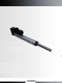
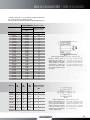
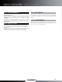
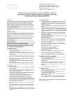
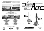
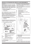
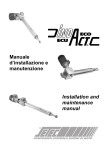
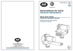
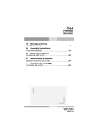
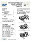
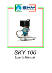
MANUALE USO E MANUTENZIONE
USE AND MAINTENANCE MANUAL
ATTUATORI MECCANICI
MECHANICAL ACTUATORS
ISO 15552 : 2004
ISOMOVE
Cert. n° EMS-2240/S
1
www.setec-group.it
Manuale uso e manutenzione ISOMOVE
ISOMOVE use and maintenance
ISOMOVE MODULO BASE - ISOMOVE BASIC MODULE
Versione con chiocciola flangiata
Flanged nut release
Tappo a tassello mobile per ingrassaggio
Sliding plug for lubrication
Versione con chiocciola filettata
Threaded
hreaded nut release
Tappo filettato per ingrassaggio
Screw plug for lubrication
Versione antirotazione in materiale plastico
Antirotation rod in plastic material release
P/N
Fig. 1
1
2
3
4
5
6
7
8
9
9B
10
11
12
13
14
15
16
16
17
18
PZ
Pcs
1
1
1
1
1
1
1
1
1
8
1
1
1
1
2
1
1
1
1
19
20
1
1
DESCRIZIONE
DESCRIPTION
TESTATA ANTERIORE
TESTATA POSTERIORE
CAMICIA ISOMOVE
ATTACCO FILETTATO
STELO
VITONE
ROTELLA
PISTONE
ASTA ANTIROTAZIONE
VITI
VITE TCCE
CUSCINETTO
GHIERA AUTOBLOCCANTE
FASCIA DI GUIDA MERKEL
ANELLO MAGNETICO
GRANO UNI 5923
CHIOCCIOLA TIPO FILETTATO
CHIOCCIOLA TIPO FLANGIATO
VITE 097F
TAPPO TCEI
TASSELLO SCORREVOLE
BOCCOLA
RASCHIATORE
FRONT HEAD
REAR HEAD
CYLINDER
SCREW CAP
EXTENSION ROD
BALLSCREW
ROLLER
PISTON
ANTIROTATION ROD
SCREWS
SCREW TCCE
BEARING
SELF-LOCKING NUT
GUIDING LINER MERKEL
MAGNETIC RING
GRUB SCREW
THREADED NUT
FLANGED NUT
SCREW 0.97 F
SCREW PLUG
SLIDING BOSS
BUSHING
SCRAPER
Antirotazione in bronzo
Bronze antirotation rod
2
www.setec-group.it
ISOMOVE VERSIONE “D” / ISOMOVE “D” VERSION
P / N PZ DESCRIZIONE
Pcs
00
21
22
23
24
25
26
27
1
1
1
4
1
4
1
1
28
1
28B
29
1
1
ISOMOVE BASE
DISTANZIALE
FLANGIA MOTORE
VITE TSEI
MOTORE
VITE TCEI
GIUNTO SERVO
FLANGIA BLOCCAGGIO
CUSCINETTO
TAPPO TCEI TASSELLO
SCORREVOLE
VITE
TAPPO A PRESSIONE
DESCRIPTION
ISOMOVE BASIC MODULE
SPACER
MOTOR FLANGE
TSEI SCREW
MOTOR
TCEI SCREW
COUPLING
BEARING COUPLING
FLANGE
SCREW PLUG
SLIDING BOSS
SCREW
CAP
Tappo filettato
per bloccaggio giunto
Thread stopper
for coupling locking screw
Fig. 2
Versione con tappo a tassello
mobile per bloccaggio giunto
Sliding plug for servo-coupling
locking screw
ISOMOVE VERSIONE “R” / ISOMOVE “R” VERSION
P / N PZ
Pcs
00
1
21
1
22
1
23
1
24
1
25
1
26
4
27
4
28
2
29
1
30
4
31
4
32
6
33
1
34
1
35
2
36
8
DESCRIZIONE
DESCRIPTION
ISOMOVE BASE
FLANGIA MOTORE
CARTER
PULEGGIA VITE
CALETTATORE
CINGHIA DENTATA
VITE TCEI
VITE TCEI
VITE TCEI
MOTORE
VITE TCEI
ROSETTA DI SICUREZZA
ROSETTA DI SICUREZZA
CALETTATORE
PULEGGIA
PANNELLO LATERALE
VITE TSEI
ISOMOVE BASIC MODULE
MOTOR FLANGE
CASING
SCREW PULLEY
SHRINK DISC
TOOTHED BELT
SCREW TCEI
SCREW TCEI
SCREW TCEI
MOTOR
SCREW TCEI
WASHER
WASHER
SHRINK DISC
PULLEY
SIDE PANEL
SCREW TSEI
Fig. 3
3
www.setec-group.it
Manuale uso e manutenzione ISOMOVE / ISOMOVE use and maintenance
IDENTIFICAZIONE
ACTUATOR DESIGNATION
Su ogni prodotto è applicata una targhetta identificativa che riporta i
principali dati che lo caratterizzano:
In every product there is a plate with all the main info about the
product you have purchased:
w w w. s e t e c - g r o u p . i t - T. + 3 9 . 0 11 . 4 5 1 8 6 11
Code N° I M – 0 5 0 – 0 5 – 0 0 5 0 – R – S 4 8
Drw
N° I – 0 0 5 0 – 0 0 0 0 – 0 0 0 – 0 0 5 0
Order N° X X X X X X X
Serial N° X X X X X X
Fig. 4
CODE: IM (ISOMOVE) – O5O (TIPO) – 05 (PASSO VITE) – 0050
(CORSA) – R (POSIZIONE MOTORE ➝ R = RINVIATO, D = DIRETTO) –
S48 (TIPO MOTORE).
Fig. 4
CODE: IM (ISOMOVE) – O5O (SIZE) – 05 (SCREW LEAD) – 0050 (STROKE)
– R (MOTOR POSITION ➝ R = BELT GEAR VERSION, D = IN LINE
VERSION) – S48 (MOTOR TYPE)
In caso di assistenza siete pregati di annotare ciascun dato in
modo da identificare il prodotto in oggetto.
If you need assistance, you are pleased to send us every data to
let us identify the product.
4.1.0 TIPOLOGIA DI IMPIEGO
4.1.0 OPERATING ENVIRONMENT
4.1.1 Temperatura di lavoro: - 20°C; +70°C
4.1.2 Grado di protezione IP: tutti gli attuatori standard sono realizzati
con grado di protezione IP54 a condizione che il motore elettrico
raggiunga tale grado di protezione.
4.1.3 Intermittenza di lavoro: tutti gli attuatori standard garantiscono
le prestazioni nominali indicate nel nostro catalogo in assenza
di urti e di vibrazioni, con carichi esclusivamente di tipo assiale
e una temperatura ambiente di 40°C.
Per condizioni differenti contattare il nostro servizio tecnico.
4.1.4 NORMATIVE
Tutti i prodotti SETEC sono costruiti in accordo alla normativa
CEE sulle macchine. come componenti di macchine i nostri
attuatori possono essere installati solo su macchinari con
caratteristiche rispondenti alla normativa comunitaria sulle
macchine secondo le seguenti:
EN 292-1, EN 2.1991, EN 954-1, EN 294.1992,
EN 349.1993, EN 418.1992
In caso di installazione dei nostri prodotti su macchinari che
non seguono le normative di legge, la SETEC non garantisce su
possibili danni arrecati agli attuatori o per l’incolumità degli
operatori.
4.2.0 INSTALLAZIONE
4.1.1 Operating temperature: - 20°C; +70°C
4.1.2 IP rating: all standard actuators are made in IP54 rating in
agreement as the standard electric motors.
4.1.3 Duty cicle: all standard actuators guarantee the nominal
performance indicated in our catalogue, in absence of impacts
and vibrations, with purely axial forces and an environment
temperature of 40°C. Contact our technical service for different
conditions.
4.1.4 COMMUNITARY RULES
All SETEC products are realized according to CEE rules about
machines; as machine elements, our actuators can be used
only inside machines in accordance with the followings
CEE rules:
EN 292-1, EN 2.1991, EN 954-1, EN 294.1992,
EN 349.1993, EN 418.1992
If our actuators are used inside equipments not according the
rules above, SETEC doesn’t garantee for possible damages or
the safety of the operators.
4.2.0 INSTALLATION
N.B. PRIMA DI RENDERE OPERATIVA LA MACCHINA OCCORRE
LEGGERE ATTENTAMENTE IL SEGUENTE MANUALE E
SEGUIRNE LE INDICAZIONI RIPORTATE; TENERE LA SEGUENTE
PUBBLICAZIONE E TUTTI I DOCUMENTI A CUI SI FA RIFERIMENTO
IN LUOGO ACCESSIBILE A CIASCUN OPERATORE E AL PERSONALE
DI MANUTENZIONE. LA SETEC SI RISERVA IL DIRITTO DI NON
PROVVEDERE ALLA RIPARAZIONE O ALLA SOSTITUZIONE IN
BEFORE STARTING THE MACHINERY, USERS MUST READ THE
FOLLOWING MAUAL; KEEP THIS AND ALL THE RELATED DOCUMENTS
IN AN A PLACE ACCESSIBLE TO THE MAINTENANCE STAFF.
SETEC COULD ASSERT THE RIGHT NOT TO REPAIR OR TO REPLACE
UNDER WARRANTY WHEN DAMAGES ARE DUE TO UNCORRECT
USE OF THE ACTUATORS OR WRONG MAINTENANCE.
4
www.setec-group.it
GARANZIA DEI NOSTRI PRODOTTI IN CASO DI DANNI DOVUTI A UN
NON CORRETTO UTILIZZO DELL’ATTUATORE E/O A UNA ERRATA
MANUTENZIONE. Per qualunque altra informazione vi rimandiamo
alla consultazione del catalogo SETEC specifico che rappresenta parte
integrante dello stesso.
4.3.0 STARTING CHECKS
4.3.0 CONTROLLI PRECAUZIONALI ALL’AVVIO
4.3.1 Tutti i nostri prodotti sono accuratamente controllati prima della
4.3.2
4.3.3
4.3.4
4.3.5
4.3.6
4.3.7
4.3.8
4.3.9
4.3.10
For any other information, consult the specific catalogue SETEC
“ISOMOVE” that is an integral part of this manual.
spedizione, tuttavia si richiede a scopo precauzionale di
verificare possibili impedimenti al movimento degli organi interni
o il serraggio delle viti delle testate.
Accertarsi che la struttura su cui è montato l’attuatore sia in
grado di sopportare il carico massimo previsto senza subire
delle deformazioni che comprometterebbero il funzionamento
dell’elettrocilindro.
N.B. I nostri attuatori sono progettati per movimentare carichi
nella sola componente assiale e un carico radiale, seppur di
piccola entità, o un carico disassato potrebbero compromettere
l’affidabilità e la durata utile del gruppo vite a ricircolo-chiocciola.
Provvedere alla pulizia dell’attuatore e nello specifico dello stelo
per evitare che impurità possano penetrare all’interno del sistema,
utilizzando prodotti idonei che non intacchino i trattamenti
superficiali dei materiali. (I nostri attuatori prevedono l’utilizzo
di un raschiapolvere che, a seconda della grandezza, può essere
interno o esterno). Polvere e abrasivi potrebbero accelerare
l’usura degli organi in movimento.
I nostri attuatori sono forniti di tappi filettati (Fig.1-18) o,
a seconda del modello, tasselli mobili impiegati per tappare il
foro ricavato sulla camicia del cilindro da utilizzare per la
lubrificazione. Verificare il corretto serraggio per impedire la
fuoriuscita di grasso lubrificante o l’ingresso di impurità nel
sistema.
È i nd i s pen sab ile a l fin e d i sal vag u ar d ar e l a d u r at a
dell’elettrocilindro evitare qualsiasi urto e/o forti vibrazioni al
sistema; è infatti risaputo che le viti a ricircolo di sfere e gli stessi
cuscinetti subiscono forti stress meccanici in caso di urto
soprattutto a cilindro fermo.
Evitare di superare i limiti di carico nominale dichiarato per
evitare gravi danni al sistema, durate fortemente ridotte e
deformazioni permanenti che pregiudicherebbero la funzionalità
dell’attuatore.
A tal scopo è buona norma, in caso di utilizzo di motori
brushless, prevedere un controllo sui picchi di coppia (fino a 5
volte il valore nominale) tipiche di questo tipo di motorizzazione.
Superare i limiti di coppia nominale in ingresso all’attuatore
potrebbe determinare gravi danni al sistema e pregiudicarne la
vita utile.
Non portare mai l’attuatore a battuta meccanica!
In caso di applicazioni in cui la traslazione è lungo l’asse verticale
occorre prevedere un sistema frenante che mantenga fermo il
carico quando il motore è spento. Il sistema vite a ricircolo- chiocciola
è infatti un sistema reversibile dote intrinseca dovuta alla bassissima
condizione di attrito interno.
Negli elettocilindri con motorizzazione rinviata la trasmissione
del moto avviene mediante cinghia dentata senza gioco in poliuretano
con rinforzi in acciaio per impedirne l’allungamento. Il tensionamento
della cinghia è predeterminato da un interasse fisso tra le pulegge
per cui non è previsto alcun tipo di tenditore.
Qualora sia indispensabile provvedere alla sostituzione della
cinghia in caso di gioco eccessivo, vi rimandiamo alla lettura del
4.3.1 All SETEC products are carefully tested before delivery; for
precautionary measure, it’s important to verify that the object
rotates freely and the correct locking of screws of the two
heads of the actuator.
4.3.2 Ensure that the structure the actuator is mounted on is
sufficiently strong to stand the maximum load without
having any deformation which could affect the good operation
of the actuator.
4.3.3 Our actuators are realized to stand only axial forces; radial or
not aligned forces could compromise the proper operation and
the reliability of the product and reduce is the its lifetime.
4.3.4 Clean the actuator and the extension rod to avoid that impurity
may enter, using the right products not to corrode the surface
of the materials. (Our actuators have inside, or outside according
to the dimension, a scraper ring). Dust and abrasives may
accelerate the wear of inner components.
4.3.5 Our actuators are supplied with screw plugs (Fig.1-18) or
sliding boss (depending on the model) to plug the hole used
for the lubrication of the ballscrew. Verify the correct tightening
to avoid the grease to go out or impurity to go in.
4.3.6 To safeguard the life time of the actuator it’s very important to
keep off any impact and vibration; it’s well-known that ball
screws and bearings are strongly stressed by impacts particularly
when the actuator is motionless.
4.3.7 Never exceed the limits of the nominal load stated in order to
avoid serious damage to the system, strongly reduced life time
and permanent deformations that could compromise the
proper operation of the actuator.
According to what has been written above, when a brushless
motor is used, you must limit torque peaks.
4.3.8 Never use the actuator inner parts as mechanical shoulder!
4.3.9 When the actuator is used in application in which the load
is moved along the vertical axis it’s necessary to provide the
actuator with a brake that stops the load when the motor is off;
it’s due to the reversibility of the ballscrew.
4.3.10 In belt gear actuators, it’s used a V-belt zero backlash polyurethane
steel reinforced belt to avoid its elongation. The tension of the belt
is stated by a fixed pulleys’ wheelbase, so no tensioning system is
there. If it’s necessary to change the belt when backlash due to wear
is there; in this case we ask you to read the following pages related
to assembling and disassembling operations.
4.3.11 “Antirotation device” is used to let the extension rod move
without rotation, when there’s no external guiding.
To avoid the rotation of the inner group (nut - piston - extension
rod) that would forbid the ballscrew to transform the rotary
movement in a linear one, it’s available the antirotation device.
It’s clear that, as a consequence, the antirotation device is
designed to stand very low torques so it mustn’t be used to
stand external torques.
When the translation of the load generates torques along the
movement’s axis it’s good that external systems could be able
to neutralize them to avoid the deformation of the extension rod
that would compromise the proper operation of the actuator.
5
www.setec-group.it
Manuale uso e manutenzione ISOMOVE / ISOMOVE use and maintenance
capitolo specifico sul montaggio e smontaggio dell’attuatore.
4.3.11 Il sistema opzionale “antirotazione” è utilizzato per permettere
la fuoriuscita dello stelo anche in quelle condizioni di assenza di
contrasto esterno.
Al fine proprio di evitare la rotazione dell’intero gruppo mobile
(chiocciola-pistone-stelo), che impedirebbe la trasformazione
del moto mediante il sistema a vite da rotatorio a traslatorio,
viene utilizzata l’antirotazione. Si evince come la coppia che
deve sopportare sia di bassissima entità per cui non può essere
in nessun modo utilizzata per vincere delle coppie esterne
anche lievi. Nei casi in cui, per effetto della traslazione del carico,
possano generarsi delle coppie lungo l’asse del moto è
indispensabile che vengano neutralizzate da sistemi esterni
all’attuatore per evitare deformazioni dell’asta antirotazione che
pregiudicherebbero il corretto funzionamento dell’attuatore.
(Per le tipologie di antirotazione disponibili Vi rimandiamo alla
descrizione generale del sistema).
4.3.12 Non ruotare mai lo stelo nelle versioni in cui è presente il sistema
antirotazione per non danneggiare l’attuatore.
4.4.0 MONTAGGIO DEL MOTORE NELLA VERSIONE
“R” RINVIATA (Fig. 3)
4.4.1
4.4.2
4.4.3
4.4.4
4.4.5
4.4.6
4.4.7
4.4.8
4.4.9
Svitare le viti (28).
Togliere il carter (22).
Posizionare e avvitare il motore (29) tramite le viti (30).
Calzare la cinghia (25) sulle pulegge (23) (34) con inseriti i
calettatori (24) e (33).
Inserire contemporaneamente la puleggia (23) sull’albero del motore e
la puleggia (34) sull’estremità della vite a ricircolo (06) [Fig. 1].
Bloccare i calettatori (24) e (35) secondo la tabella “C” relativa
ai calettatori (per la tipologia del calettatore verificare le dimensioni).
Controllare il perfetto parallelismo e allineamento delle pulegge.
Riposizionare il carter (22).
Inserire e bloccare le viti (28).
4.5.0 MONTAGGIO DEL MOTORE NELLA VERSIONE
“D” DIRETTA (Fig. 2)
4.5.1 Posizionare il giunto (26) sull’alberino del motore (24) verificando
4.5.2
4.5.3
4.5.4
4.5.5
che la posizione assiale del giunto, una volta accoppiato al
motore ed inserito nella campana (22), sia tale da permettere il
raggiungimento della apposita vite di bloccaggio del giunto
stesso tramite il foro ricavato sul distanziale (21).
Sfilare il motore (24) e serrare il giunto (26) sull’albero del motore
agendo sulla vite apposita, rispettando le coppie di serraggio riportate
nella tabella “D”. (Per la tipologia del giunto, verificare la sigla
riportata sul giunto stesso).
Posizionare il motore (24) completo di giunto (26) sulla campana (22)
e bloccare il medesimo con le viti (25).
Bloccare il giunto (26) sulla vite a ricircolo (06) [Fig. 1] ,facendo
riferimento alla tabella “D”, mediante il foro presente sul distanziale (21).
Tappare il foro sul distanziale (21) mediante il tappo (28) che, a
seconda del modello, potrà essere filettato o a tassello mobile.
(For types of antirotation device you are asked to see the
general description of the actuator).
4.3.12 Never rotate the extension rod when the antirotation
device is there not to damage the actuator!
4.4.0 MOUNTING MOTORS IN BELT GEAR
VERSION “R” (Fig. 3)
4.4.1
4.4.2
4.4.3
4.4.4
4.4.5
4.4.6
4.4.7
4.4.8
4.4.9
Unscrew screws (28).
Remove casing (22).
Put in position the motor and screw it (29) using screws (30).
Set the belt (25) on pulleys (23) (34) with sleeves inside (24)
and (33).
Insert at the same time the pulley (23) on motor shaft and
the pulley (34) on the back of the ballscrew (06) [Fig. 1].
Lock the shrink disc (24) and (35) according to the Tab “C” about
shrink disc (check sleeves’ type seeing the identification plate).
Check the perfect alignment and parallelism of pulleys’ axis.
Position the casing (22).
Insert and block screws (28).
4.5.0 MOUNTING MOTORS IN LINE
VERSION “D” (Fig. 2)
4.5.1 Put in position the servo coupling (26) on motor shaft (24)
4.5.2
4.5.3
4.5.4
4.5.5
verifying that axial servo coupling position, once joined to the
motor and inserted in the flange (22), permits to reach the locking
screw of the servo coupling through the hole in spacer (21).
Pull out the motor (24) and tighten the servo coupling’s
screw (26) on motor’s shaft, according to the Tab “D”.
(Check servo coupling’s type seeing identification plate).
Position motor (24) with servo coupling in (26), on flange (22)
and lock it with screws (25).
Grip servo coupling (26) to the ballscrew (06) [Fig. 1],
according to the Tab “D”, through the hole in spacer (21).
Plug the hole in spacer (21) using the screw plug (28) that,
on the base of the model, would be made as a sliding boss too.
4.6.0 ORDINARY MAINTENANCE AND SCHEDULED
CONTROLS
4.6.1 A suitable maintenance with a correct use avoids problems
in terms of reliability and safety, furthermore it guarantees
functionality and quality through the product life; so we ask
you to have a scrupulous care of scheduled maintenance in
the summarizing tab below (Tab. “A”).
4.6.0 MANUTENZIONE ORDINARIA E CONTROLLI PERIODICII
4.6.1 Una buona manutenzione del sistema, insieme ad un corretto utilizzo,
evitano problemi legati all’affidabilità e alla sicurezza garantendone
funzionalità e qualità nel tempo, per cui vi chiediamo di seguire
scrupolosamente gli interventi di manutenzione programmata
riassunti nella tabella di seguito (Tab. “A”):
6
www.setec-group.it
INTERVALLO
FREQUENCY
PARTICOLARE
PART
Dopo 2 MESI dall'installazione
2 months after installation
VITI TESTATE
Entro 6 mesi
HEAD SCREWS
Within 6 months
INTERVENTO
TYPE CHECK
CONTROLLO SERRAGGIO
TIGHTEN SCREWS
Rif.
Ref.
montaggio - manuale d'uso
mounting - use guide
500 ore / hours
VITE A RICIRCOLO
LUBRIFICAZIONE / LUBRICATION
Manutenzione - manuale d'uso / Maintenance - use guide
BALLSCREWS
GIOCO CHIOCCIOLA / NUT BACKLASH
Catalogo VITI a sfere SETEC / SETEC ballscrew catalogue
12-18 MESI
Every 12-18 MONTHS
GIUNTO / SERVO COUPLING
CONTROLLO SERRAGGIO / TIGHTEN SCREWS
Montaggio - manuale d'uso / Mounting - use guide
12 / 18 MESI
Every 12 / 18 MONTHS
CALETTATORI / SHRINK DISCS
CONTROLLO SERRAGGIO / TIGHTEN SCREWS
Montaggio - manuale d'uso / Mounting - use guide
12 / 18 MESI
Every 12 / 18 MONTHS
CINGHIA DENTATAI / V BELT
CONTROLLO GIOCO / CHECK BACKLASH
Manutenzione - manuale d'uso / Maintenance - use guide
12 / 18 MESI
Every 12 / 18 MONTHS
PULEGGIA / PULLEY
VERIFICA ALLINEAMENTO / CHECK ALIGNMENT
Controlli all'avvio - manuale d'uso / Starting check - use guide
* In condizioni di carico e di utilizzo gravosi dimezzare gli intervalli di manutenzione dichiarati.
* In heavy load and use condition double the frequency of planned maintenance.
Tab. “ A”
Tab. “A”
4.6.2 CONTROLLO SERRAGGIO:
4.6.2 SCREW TIGHTENING CHECK:
4.6.2.1 VITI DI FISSAGGIO TESTATE: verificare il serraggio delle viti
4.6.2.1 HEAD SCREWS:verify screw tightening using the specific tool;
mediante bussola specifica; in caso di condizioni gravose e con
forti vibrazioni intensificarne il controllo (per le coppie di
serraggio vedere Tab. “B”);
4.6.2.2 GHIERA AUTOBLOCCANTE: la ghiera per il blocco del cuscinetto
ha il compito di vincolare assialmente la vite. L’insorgenza di
gioco, dovuto a condizioni anomale di funzionamento, potrebbe
pregiudicare la durata del cuscinetto e la precisione di posizionamento
dell’attuatore. Per l’accesso alla ghiera vi rimandiamo al capitolo
“montaggio e smontaggio”.
4.6.2.3 GIUNTO DI TRASMISSIONE: il giunto ha il compito di trasmettere
il moto in caso di motorizzazione “D” diretta tra l’albero motore
e la vite a ricircolo. I giunti utilizzati sono del tipo a gioco zero e
adottano un collegamento a morsetto.
Per evitare slittamenti che pregiudicherebbero la precisione di
posizionamento dell’attuatore occorre verificare periodicamente
il serraggio utilizzando chiavi dinamometriche (le coppie sono
riportate nella tabella “D”).
Per la tipologia di giunto vedere la sigla riportata sul giunto
stesso. Per l’accesso al giunto vi rimandiamo al capitolo
“montaggio e smontaggio“.
4.6.2.4 CALETTATORE: il calettatore ha il compito di bloccare le pulegge
sul relativo albero, assicurarsi quindi che lo stesso sia sempre
ben bloccato. Le coppie di serraggio sono riportate nella Tab.
“C”. Per la tipologia di calettatore vedere le dimensioni dello
stesso. Per l’accesso ai calettatori vi rimandiamo al capitolo
“montaggio e smontaggio”.
4.6.2.5 Gli attuatori vengono forniti con sistema di bloccaggio dei filetti
delle viti di serraggio (Loctite morbida); nel caso di acquisto di
attuatori in versione custom, per consentire il montaggio del
motore, alcune viti non vengono bloccate.
in heavy load applications, or in presence of vibrations, intensify
the control (see Tab. “B”).
4.6.2.2 SELFLOCKING NUT: the selflocking nut has the task to axially
constrain the ballscrew. The birth of backlash, due to abnormal
working conditions, could reduce the life time of bearings and
the correct actuator’s positioning accuracy.
To get to the self locking nut, see the “mounting and
disassembling” chapter.
4.6.2.3 SERVO COUPLING: the servo coupling is used to transmit the
power, in “D” ISOMOVE version, between motor shaft and
ballscrew.
The coupling is “zero” backlash type; to avoid sleepery
condition that could create a bad positioning, it’s important to
check the tightening of its locking screw through a dynamometric
key (see Tab “D” for tightening torque). Check servo coupling’s
type seeing identification plate. To get to the servo coupling,
see the “mounting and disassembling” chapter.
4.6.2.4 SHRINK DISC: it has the task to lock the pulley on relative shaft, be
sure that it is always locked (see Tab “C” for tightening torque).
Check servo coupling’s type seeing identification plate.
To get to the servo coupling, see the “mounting and disassembling”
chapter.
4.6.2.5 In our actuators all the screws are blocked using the “LOCTITE”
thread locking system; when a custom actuator is bought, to
allow motor installation some screws aren’t locked.
Once the motor mounted, we suggest you to apply the LOCTITE
system.
7
www.setec-group.it
Manuale uso e manutenzione ISOMOVE / ISOMOVE use and maintenance
Si consiglia, una volta effettuato il montaggio, di applicare della
Loctite morbida. Più in generale di seguito vengono allegate le tabelle
relative alle norme sul serraggio; la seguente norma stabilisce i valori
della coppia nominale e relative tolleranze da applicare per il serraggio
della bulloneria in funzione delle applicazioni. Per la scelta delle classi
di serraggio, consultare la Tab.B1 e definire il bullone da utilizzare,
riportato in Tab.B2, considerando le forze di trazione di ogni singolo
bullone (Tab. B3).
In the tabs below you can find the values of tightening torque of the
screws according to the Community rules; the following rule sets
torque and tolerance values to apply for tightening screws on the
base of applications.
To choose the tightening class, consult Tab. B1 and define the
screw to use, seeing Tab B2, according to the strength of every
screw (Tab B3)
Classe di serraggio
Tightening class
Applicazioni
Applications
Tolleranze riferite alla coppia funzionale
Tolerances according to nominal torque
I
MOLTO IMPEGNATIVE
VERY HEAVY
±5%
II
IMPEGNATIVE
HEAVY
5%
-15%
III
POCO IMPEGNATIVE
NOT HEAVY
5%
-35%
Tab. “B1”
Filettatura
THREAD
Apertura chiave
della vite e/o del dado
Screw’s tool
7
8
10
13
17
19
22
24
27
30
32
36
41
46
M4
M5
M6
M8
M10
M12
M14
M16
TABELLA B! B” B£M18
M20
M22
M24
M27
M30
7
8
10
13
17
19
22
24
27
30
32
36
41
46
[ N]
[ Nm]
M4
M5
M6
M8
M10
M12
M14
M16
M18
M20
M22
M24
M27
M30
CLASSE DI SERRAGGIO / TIGHTENING CLASS
III
II
I
CLASSE DI RESISTENZA DELLA VITE / SCREW STRENGHT CLASS
8,8
10,9
12,9
CLASSE DI RESISTENZA DEL DADO / NUT STRENGHT CLASS
8
10
12
2,3
4,8
8
20
39,2
68,8
108
168
232
328
440
568
840
1160
3,3
6,8
11,2
28
55,2
96
152
236
324
464
624
800
1200
1600
3120
4360
5080
7160
7200
10080
13200
18560
20960
29520
b3
30640 TABELLA b1 b2 43200
42000
59200
58400
81600
70400
99200
91200
128000
112800
159200
131200
184000
172000
241600
209600
294400
4
8
13,6
32,8
66,4
116
184
284
388
552
744
960
1440
1920
5240
8560
12080
22320
35440
51600
70800
98400
118400
153600
191200
220800
290400
253600
Tab. “B2”
Coppia di
serraggio
Tightening
torque
Tab. “B3”
Forza
di trazione
Axial
strenght
8
www.setec-group.it
4.6.3
CONTROLLO GIOCHI
4.6.3
BACKLASH CHECK
4.6.3.1 CUSCINETTO: il cuscinetto impiegato è del tipo a gioco ”zero”
4.6.3.1 BEARINGS: the bearings used in our actuators are angular
a doppio contatto obliquo, tuttavia in condizioni di funzionamento
gravose è opportuno verificare il gioco assiale per non avere
errori di posizionamento dell’attuatore e una rapida usura del
componente. Qualora si siano verificati dei giochi procedere
alla sostituzione del cuscinetto stesso.
Per l’accesso al cuscinetto vi rimandiamo al capitolo
“ montaggio e smontaggio “ .
4.6.3.2 CINGHIA DENTATA: non è prevista la possibilità di regolare il
tensionamento della cinghia; se in condizioni particolari dovesse
verificarsi un allungamento della cinghia provvedere alla
sostituzione. Per l’accesso alla cinghia vi rimandiamo al capitolo
“montaggio e smontaggio”.
4.6.3.3 VITE A RICIRCOLO / CHIOCCIOLA: la chiocciola viene fornita
sempre con gioco assiale il cui valore è dichiarato nel catalogo
SETEC (viti a ricircolo di sfere). Qualora in condizioni particolari
il gioco assiale dovesse superare il valore massimo nominale
occorre sostituire il sistema vite/chiocciola per non incorrere in
errori di posizionamento.
contact double rows “zero” backlash type; in heavy working
condition it’s important to control the axial backlash to avoid
positioning errors of the actuator and a quick wear of the
component.
To get to the bearing , see the “mounting and disassembling”
chapter.
4.6.3.2 V-BELT: it’s not available a tensioning system; change the
belt if its length should abnormally increase. To the access to
the v-belt , see the “ mounting and disassembling “ chapter.
4.6.3.3 BALLSCREW / NUT: the standard nut is with axial backlash;
you can find the value of the backlash in the SETEC ballscrew
catalogue. If, in particular working condition, the backlash
should exceed the maximum nominal value it is necessary to
replace the ballscrew not to have positioning errors.
4.6.4
LUBRIFICAZIONE
4.6.4.1 L’attuatore viene fornito con la vite a ricircolo completamente
lubrificata; essendo il sistema totalmente sigillato, la fase di
lubrificazione può avvenire ad intervalli piuttosto ampi (vedi
par. 4.6 Tab. “A” ), tuttavia una periodica lubrificazione contribuisce
a limitare la rumorosità, ridurre le coppie d’attrito e quindi il
calore generato. I lubrificanti impiegabili sono i medesimi utilizzati
per la lubrificazione dei cuscinetti.
4.6.4.2 La lubrificazione è del tipo manuale e può avvenire introducendo
direttamente un ugello all’interno della camicia dell’attuatore ed
erogando il lubrificante direttamente sulla vite; per questa
operazione occorre far riferimento alla seguente procedura
(vedi Fig. 5 per schema di lubrificazione):
4.6.4.2.1 far fuoriuscire lo stelo (05) fino a fondo corsa in modo da aver
libero accesso alla vite (06).
4.6.4.2.2 svitare il tappo (18) o la vite del tassello mobile laddove previsto.
4.6.4.2.3 introdurre l’ugello attraverso il foro sulla camicia (03)
dell’attuatore fino a raggiungere la vite (06).
4.6.4.3 Evitare di introdurre quantità eccessive di grasso per non
pregiudicare il corretto funzionamento dell’attuatore.
4.6.4
LUBRICATION
4.6.4.1 Before delivering, the ballscrew of the actuator is completely
lubricated; as it is totally sealed, the lubrication can be made
with a low frequency (see Par.6 Tab. “A”), however a recurring
lubrication may reduce noise, friction torques and then heat
generation.
4.6.4.2 The lubrication can be realized by hand introducing the nozzle
into the cylinder and distributing the grease directly on screw;
to do that, see the following procedure (see Fig. 5 below):
4.6.4.2.1 the extension rod (05) up to stroke end (06).
4.6.4.2.2 unscrew plug (18) or the screw of the sliding boss where
provided.
4.6.4.2.3 introduce the nozzle through the hole in the cylinder (03)
to reach the ballscrew (06).
4.6.4.3 In order not to damage the actuator, do not put in a quantity
of grease bigger than the required value.
SCHEMA DI LUBRIFICAZIONE ISOMOVE / ISOMOVE LUBRIFICATION CHART
Foro su camicia
Hole in cylinder
Passaggio attraverso foro per lubrificazione diretta della vite
Way to lubrificate directly the ballscrew
Stelo in posizione estesa
Extension rod in external position
FIGURA / FIGURE 5
Chiocciola
Nut
Vite a ricircolo
Ballscrew
9
www.setec-group.it
Manuale uso e manutenzione ISOMOVE / ISOMOVE use and maintenance
4.6.4.4
L’intervallo di lubrificazione può essere mediamente pari a
500 ore di funzionamento; questa prescrizione è soltanto
indicativa e può variare in funzione del tipo di applicazione.
Per un approfondimento si rimanda a consultare il catalogo
viti a ricircolo SETEC.
4.6.5
VERIFICA USURA
4.6.5.1
BOCCOLA ANTIFRIZIONE: lo stelo (05 - Fig.1) è vincolato
radialmente in quanto guidato da una boccola (19 - Fig. 1)
in materiale a basso attrito.
Qualora si verificasse un gioco radiale controllare il corretto
impiego dell’atuatore e, se necessario, sostituire la boccola
stessa.
Per l’accesso alla boccola vi rimandiamo al capitolo
“montaggio e smontaggio“.
FASCIA DI GUIDA MERKEL: trattasi di fascia in materiale
polimerico impiegata sul pistone come antifrizione nel
contatto con la camicia.
In condizioni di corretto impiego dell’attuatore non si deve
verificare un consumo della fascia di guida pertanto verificare
sempre il montaggio dell’elettrocilindro in caso di insorgenza
di gioco radiale dello stelo e quindi del pistone.
4.6.5.2
4.6.4.4
The frequency of lubrication is 500 working hours; this is an
indicative instruction and it could change on the base of the
application.
See also SETEC “ BALLSCREW “ catalogue to have more info.
4.6.5
WEAR CHECK
4.6.5.1
BUSHING: the extension rod (05 - Fig.1) is radially
constrained because leaded by an antifriction bushing
(19 - Fig. 1).
Should a radial backlash arise, control that the actuator is cor
rectly used and, if necessary, replace the bushing.
To get to the bushing, see the “ mounting and disassembling “
chapter.
INNER LINER MERKEL: it’s a ring in polymeric material
used on the piston as antifriction guiding system into the
cylinder. In a correct use of the actuator the ring will not
wear out; should this happen, verify that the actuator is
correctly mounted in the machinery.
4.6.5.2
4.7.0 EXTRAORDINARY MAINTENANCE
4.7.1
In all cases in which, during the ordinary maintenance, it’s need
to disassemble the actuator, read the followings pages.
4.7.2
DISASSEMBLING
4.7.2.1
4.7.2.1.1
4.7.2.1.2
4.7.2.1.3
4.7.2.1.4
ISOMOVE BASIC MODULE (Fig. 1):
Unscrew with specific tool screws (10) of the HEADS (01 -02).
Remove the HEAD (01) from the EXTENSION ROD (05).
Remove SCRAPER (20) and the BUSHING (19).
Unscrew the SELF-LOCKING NUT (12) from the
BALLSCREW (06).
Remove the BEARING (11) through the hole of the HEAD
(02) and from the BALLSCREW (06).
Remove the HEAD (02) from the BALLSCREW (06).
Remove the CYLINDER (03) from the EXTENSION
ROD/PISTON/BALLSCREW group.
Remove the ANTIROTATION DEVICE (09) from the CYLINDER
(03) [where available, unscrew screws (9B) to remove
the antirotation device].
Unscrew the GRUB SCREWS (15) from the PISTON (08).
Unscrew the EXTENSION ROD (05) from the PISTON (08).
Unscrew the PISTON (08) from the NUT in threaded NUT
release unscrew the screws from the flange of the NUT (16)
in flanged NUT release.
Remove INNER LINER MERKEL (13) and MAGNETIC RING
(14) from PISTON (08).
Move the NUT (16) near the end of BALLSCREW (06).
4.7.0 MANUTENZIONE STRAORDINARIA
4.7.1
In tutti i casi in cui durante la manutenzione ordinaria si renda
necessario lo smontaggio dell’attuatore è opportuno leggere
le seguenti indicazioni per il montaggio e lo smontaggio.
4.7.2
SMONTAGGIO
4.7.2.1
4.7.2.1.1
4.7.2.1.2
4.7.2.1.3
4.7.2.1.4
4.7.2.1.5
VERSIONE ISOMOVE BASE (Fig. 1):
Svitare con apposita bussola le viti (10) delle TESTATE (01 - 02).
Sfilare la TESTATA (01) dallo STELO (05).
Estrarre il RASCHIAPOLVERE (20) e la BOCCOLA (19).
Svitare la GHIERA (12) dal codolo della VITE (06).
Sfilare il CUSCINETTO (11) dal foro della TESTATA (02) e dal
codolo della VITE (06).
Sfilare la TESTATA (02) rispetto al codolo posteriore della
VITE (06).
Sfilare la CAMICIA (03) dal gruppo STELO/PISTONE/VITE.
Estrarre l’asta ANTIROTAZIONE (09) dalla CAMICIA (03)
[laddove previsto occorre svitare le VITI (9B) per liberare
l’ANTIROTAZIONE].
Svitare i grani (15) dal PISTONE (08).
Svitare lo STELO (05) dal PISTONE (08).
Svitare il PISTONE (08) dalla CHIOCCIOLA (16) nelle versioni
a chiocciola filettata; rimuovere le viti di fissaggio della flangia
della CHIOCCIOLA (16) nelle versioni a chiocciola flangiata.
Rimuovere FASCIA MERKEL (13) e ANELLO MAGNETICO
(14) dal PISTONE (08).
Portare la CHIOCCIOLA (16) verso l’estremità della VITE (06).
4.7.2.1.6
4.7.2.1.7
4.7.2.1.8
4.7.2.1.9
4.7.2.1.10
4.7.2.1.11
4.7.2.1.12
4.7.2.1.13
4.7.2.1.5
4.7.2.1.6
4.7.2.1.7
4.7.2.1.8
4.7.2.1.9
4.7.2.1.10
4.7.2.1.11
4.7.2.1.12
4.7.2.1.13
N.B. Per non far fuoriuscire le sfere durante lo sfilamento
della chiocciola è indispensabile interporre un tubo con
diametro esterno pari al diametro corrispondente alle
piste di rotazione delle sfere sulla vite e lunghezza superiore
alla chiocciola.
Per maggiori dettagli vi rimandiamo a consultare il
catalogo SETEC viti a ricircolo.
To avoid the exit of balls from the nut when you are
unscrewing it from the ballscrew, it’s very important to
interpose a tube with the external diameter equal to the
balls’ liner of the ballscrew and a length greater then the
nut’s one.
For more info, consult SETEC “BALLSCREW” catalogue.
10
www.setec-group.it
4.7.2.2
VERSIONE CON MOTORIZZAZIONE DIRETTA (Fig. 2)
4.7.2.2
4.7.2.2.1 Rimuovere il TAPPO filettato (28) o le VITI (28B) del TASSELLO
a SCORRIMENTO (28).
DIRECT DRIVE PACKAGE ISOMOVE “D”
RELEASE (Fig. 2)
4.7.2.2.1 Remove the SCREW PLUG (28) (or screws (28B) from the
SLIDING BOSS PLUG (28).
4.7.2.2.2 Muovere lo STELO (05) per mettere in rotazione il GIUNTO
4.7.2.2.2 Move the EXTENSION ROD (05) to make the SERVO
4.7.2.2.7
(26) finchè la vite di serraggio del morsetto risulta accessibile
passando attraverso il foro sul DISTANZIALE (21) (nelle versioni
con TAPPO a PRESSIONE (29) il processo potrebbe non
richiedere di movimentare lo stelo ).
Svitare le VITI (25) e rimuovere il motore (24).
Rimuovere il GIUNTO (26) dall’albero motore intervenendo
sull’apposita vite del morsetto.
Svitare le VITI (23) e sfilare la FLANGIA MOTORE (22) e il
DISTANZIALE (21).
Rimuovere il GIUNTO (26) dalla VITE A RICIRCOLO
intervenendo sull’apposita vite del morsetto.
Sfilare la FLANGIA BLOCCAGGIO CUSCINETTO (27).
4.7.2.2.7
COUPLING (26) rotate till its locking screw become
accessible passing through the hole in SPACER (21)
(in release with CAP (29) you needn’t move the extension rod).
Unscrew SCREWS (25) and remove MOTOR (24).
Remove SERVO COUPLING (26) from the motor’s shaft
unscrewing its fixing screw.
Unscrew the SCREWS (23) and remove MOTOR FLANGE
(22) and SPACER (21).
Remove SERVO COUPLING (26) from the BALLSCREW
unscrewing its locking screw.
Remove the BEARING COUPLING FLANGE (27).
4.7.2.3
VERSIONE CON MOTORIZZAZIONE RINVIATA (Fig. 3)
4.7.2.3
BELT GEAR PACKAGE ISOMOVE “R” RELEASE (Fig. 3)
4.7.2.2.3
4.7.2.2.4
4.7.2.2.5
4.7.2.2.6
4.7.2.3.1 Svitare le VITI (27 - 28) e rimuovere il CARTER (22) per
4.7.2.2.3
4.7.2.2.4
4.7.2.2.5
4.7.2.2.6
4.7.2.3.1 Unscrew SCREWS (27 - 28) and remove CASING (22) to
accedere al gruppo di trasmissione rinviato.
have access to the belt gear transmission group.
4.7.2.3.2 Allentare i CALETTATORI (33 - 24) intervenendo sulle apposite
4.7.2.3.2 Loosen SHRINK DISC (33 - 24) by its screws and take out
viti ed estrarre la CINGHIA (25) e le PULEGGE (23 - 34).
BELT (25) and PULLEYS (23 - 34).
4.7.2.3.3 Svitare le VITI (30).
4.7.2.3.4 Sfilare il MOTORE (29)
4.7.2.3.5 Svitare le VITI (26) ed estrarre il corpo ISOMOVE BASE (00).
4.7.3
4.7.2.3.3 Unscrew SCREWS (30).
4.7.2.3.4 Pull out the MOTOR (29).
4.7.2.3.5 Unscrew the SCREWS (26) and remove BASE ISOMOVE
(00) group.
MONTAGGIO
ASSEMBLY
4.7.3.1 In via generale ripercorrendo a ritroso la procedura di smontaggio
4.7.3
delle relative versioni (vedere inoltre Par. 4 e 5) è possibile
effettuare il montaggio, prestando una particolare cura
all’assemblaggio delle seguenti parti:
4.7.3.1.2 VITE A RICIRCOLO / CHIOCCIOLA (entrambe le versioni, filettata
e flangiata)
In caso di sostituzione della chiocciola vi verrà fornito il
componente su cui è presente un tubetto; non sfilare mai il
tubetto, pena la fuoriuscita delle sfere!
Il tubetto deve essere sfilato dalla chiocciola a mano a mano
che la chiocciola si avvita sul filetto della vite a ricircolo.
La sezione del tubetto deve appoggiare proprio sull’inizio del
filetto della vite a ricircolo senza discontinuità; le sfere rotolano
su un diametro approssimativamente pari al diametro esterno
del tubetto, in questo modo le sfere possono essere trattenute
dentro la sede della chiocciola fino a trovare l’inizio del filetto
della vite.
In caso di approfondimenti vi rimandiamo al catalogo
”viti a ricircolo” SETEC.
4.7.3.1.3 CINGHIA DENTATA
Per evitare stress eccessivi ai cuscinetti degli alberi su cui
sono calettate le pulegge e per evitare disallineamenti, in caso
di sostituzione della cinghia, è bene allentare le viti dei
CALETTATORI (24 - 33) al fine di ridurre il tensionamento da
applicare alla cinghia. Stringendo i calettatori si ottiene
automaticamente il tensionameto e il centraggio adeguato.
In ultima analisi occorre sempre verificare l’allineamento
della cinghia verificando che la stessa non si intraversi.
4.7.3.1.4 CALETTATORI E GIUNTI
Al fine di garantire l’adeguata trasmissione del moto dall’albero
motore alla vite è indispensabile che le viti dei giunti e dei
calettatori vengano serrate secondo la corretta coppia di
4.7.3.1 Generally speaking if you follow disassembling procedure in
the opposite sequence it’s possible to assemble the unit,
taking good care of the following parts:
4.7.3.1.2 BALLSCREW (both threaded and flanged NUT release when
you need to replace the nut, the new component will be sent
with a tube inserted in; never extract the tube, the balls
would fall down.
The tube must be pulled out from the nut while it’s screwing
on the screw; the tube must be laid at the starting thread of
the screw without discontinuity; balls roll on a diameter
equal to the external diameter of the tube, so that the balls
can be retained inside the nut’s liners till they reach the thread
of the ballscrew.
For more info, consult SETEC “BALLSCREW” catalogue.
4.7.3.1.3 V-BELT
To avoid stresses and misalignment of the shafts on which
the pulleys are coupled, when you must replace the v-belt,
it’s important to unscrew the locking screws of the SHRINK
DISCS (24 - 33) to reduce belt tensioning.
By locking the shrink discs you can obtain the right tension
and centering at the same time. At the end, always verify the
alignment of the belt checking it moves properly without veering.
4.7.3.1.4 SHRINK DISCS AND SERVO COUPLING
To guarantee the right power transmission from the motor
shaft to the ballscrew, shrink discs and servo coupling’s
screws have to be locked according to the correct tightening
torque (see Tab. “C” referred to sleeves’ torque and Tab. “D”
referred to servo coupling’s torque).
To check the shrink disc and servo coupling’s type see the
identification plate.
11
www.setec-group.it
Manuale uso e manutenzione ISOMOVE / ISOMOVE use and maintenance
serraggio. (Vedere Tab. “C” per le coppie di serraggio dei calettatori e
Tab. “D” per le coppie di serraggio dei giunti.
Per il tipo di giunto e calettatore verificare la sigla riportata sugli stessi.
VITI DI SERRAGGIO / LOCKING SCREWS
DIN 912
mm
12,9
Coppia di serraggio
Tightening torque
dXD
N° x tipo / type
Nm
6 x 16
6,35 x 16
7 x 17
8 x 18
9 x 20
9,53 x 20
10 x 20
11 x 22
12 x 22
14 x 26
15 x 28
16 x 32
17 x 35
18 x 35
19 x 35
20 x 38
22 x 40
24 x 47
25 x 47
25,4 x 47
28 x 50
30 x 55
32 x 55
35 x 60
38 x 65
40 x 65
42 x 75
45 x 75
48 x 80
50 x 80
3 x M2,5
3 x M2,5
3 x M2,5
3 x M2,5
4 x M2,5
4 x M2,5
4 x M2,5
4 x M2,5
4 x M2,5
4 x M3
4 x M3
4 x M4
4 x M4
4 x M4
4 x M4
4 x M5
4 x M5
4 x M6
4 x M6
4 x M6
6 x M6
6 x M6
6 x M6
8 x M6
8 x M6
8 x M6
6 x M8
6 x M8
8 x M8
8 x M8
1,2
1,2
1,2
1,2
1,2
1,2
1,2
1,2
1,2
2,1
2,1
4,9
4,9
4,9
4,9
10
10
17
17
17
17
17
17
17
17
17
41
41
41
41
Tab. “C”
Coppie Serraggio Calettatori / Shrink discs’ tightening torque
Misurare il diametro interno di
calettamento della puleggia e il
diametro dell’albero; in base al dato
ottenuto identificare il calettatore
corrispondente e prendere nota
della corretta coppia di serraggio
nella colonna denominata “Coppia
di serraggio”.
Tipo / Type
D1
mm
D2
mm
DIN
912
Coppia di serraggio
Tightening torque
Nm
ADS 10
6
16
M4
5
ADS 18
10
24
M5
10
ADS 60
14
32
M6
18
ADS 150
16
38
M8
43
ADS 300
24
45
M 10
84
DKN 20/42
3
12,7
M3
1
It’s possible to identify the right
shrink disc by measuring the
inner pulley and screw diameter;
on the base of these values you
can find the tightening torque
regarding the shrink disc choosen.
Tab. “D”
Coppie Serraggio Giunti / Coupling’s tightening torque
Misurare i diametri dell’albero del
motore e del codolo della vite;
in base ai dati ottenuti identificare
il giunto corrispondente e prendere
nota della corretta coppia di
serraggio nella colonna denominata
“Torque to Tighten Clamps”.
It’s possible to identify the right
coupling by measuring the motor
shaft and screw diameter; on the
base of these values you can find
the tightening torque regarding
the coupling choosen.
12
www.setec-group.it
Manuale uso e manutenzione ISOMOVE / ISOMOVE use and maintenance
4.8.0 FINECORSA MAGNETICI
4.8.0 LIMIT SWITCHES
Tutti gli attuatori sono muniti di anelli magnatici (14 - Fig. 1) montati
sul pistone (08 - Fig. 1).
A richiesta possono essere forniti i finecorsa magnetici da alloggiare
direttamente nelle cave dell’estruso con cui è realizzata la camicia
(03 - Fig. 1).
Insieme con i finecorsa magnetici verrà fornita la relativa
documentazione a cui chiediamo di fare riferimento in caso di uso e
manutenzione.
4.9.0 MOTORI ELETTRICI
Every actuator is supplied with a magnetic ring (14 - Fig. 1) mounted
on the piston (08 - Fig. 1); on request reed sensors are available,
they can be housed directly in the slots of the aluminium extruded
profile.
4.9.0 ELECTRIC MOTORS
Our actuators can be supplied with motors; see par. 4 and 5 to see
how to install the motor; you’ll receive the documentation, we ask
you to refer to, for use and maintenance.
Gli attuatori possono essere forniti completi di motorizzazione.
Per il montaggio sull’attuatore vedere, in base alla tipologia, i
paragrafi 4 e 5.
Insieme con i motori verrà fornita la relativa documentazione a cui
chiediamo di fare riferimento in caso di uso e manutenzione.
13
www.setec-group.it