1
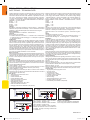
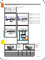
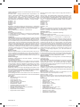
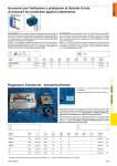
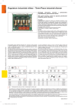
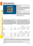
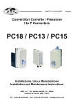
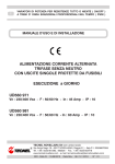
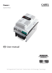
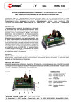
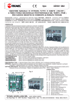
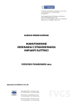
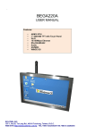
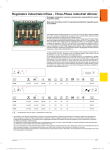
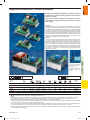
since 1967
Regolatore industriale - Industrial dimmer
Montaggio retroquadro equipaggiato di filtri EMC, comando a
potenziometro separato (fornito), regolazione della tensione
minima e massima.
RTS40N
Back panel mounting equipped with EMC filters, separate
potentiometer (supplied), dimming of minimum and maximum voltage.
RTS39
Generalità
L’apparecchiatura consente di variare con continuità la tensione ai capi
dell’utilizzatore variandone il valore efficace da zero ad una tensione pari al
95% della tensione di alimentazione. Impiega come componente il TRIAC
(interruttore elettronico) che ne determina la massima potenza di impiego.
La variazione di tensione si effettua manualmente ruotando la manopola
del potenziometro (a corredo). Sulla scheda sono presenti i trimmer per la
regolazione della tensione minima e massima. L’apparecchiatura è dotata
di filtri LC e RC rispondenti alle normative vigenti, il ronzio durante il funzionamento è fisiologico e generato dai filtri stessi.
General
The appliance allows continual variation of the voltage supplied to the device ‘s ends varying the effective value from zero to a voltage equal to
95% of the voltage power supply. It uses TRIAC (electronic switch) components that determine its maximum use power. Voltage variations are
carried out manually by rotating the knob on the potentiometer (provided).
Trimmers are available for regulating the minimum and maximum voltage.
The appliance is fitted with LC and RC filters in compliance with existing
laws in force. The buzzing noise during function is physiological and is
generated by the filters.
RTS36
RTS38N
RT38CE
Tutti i modelli sono
completi di potenziometro, targhetta e
manopola.
Complete with potentiometer, plate and
knob
*
*
*
•
Articolo
Article
Codice
Code
RTS36
3
50÷700
50÷370
230÷240
50
132
63
70
1
RN0344
RTS38N
6
50÷1400
50÷800
230÷240
50
167
74
85
1
RN0420
RT38CE NEW
6
150÷1400
-
230÷240
50
110
80
110
1
RN0419CE
RTS39
10
50÷2300
50÷1500
230÷240
50
180
108
102
1
RN0351
RTS40N
16
50÷3700
50÷2600
230÷240
50
204
120
103
1
RN0436
RT40CE NEW
20
150÷5000
-
230÷240
50
110
80
180
1
RN0435CE
•
FLUORESCENTI
VARIALUCE- -FLUORESCENT
DIMMER
RT40CE
Declassamento solo per motori - Declassing for motors only
* Si consiglia di non utilizzare trasformatori o aspiratori con potenza superiore a 300VA, la potenza è riferita al singolo trasformatore o ventilatore.
Potenze maggiori potrebbero causare un surriscaldamento dell’utilizzatore con conseguente danneggiamento. E’ consentito quindi il
raggiungimento della piena potenza di targa del regolatore con più trasformatori o aspiratori da 300VA.
La regolazione di trasformatori elettromeccanici è caratterizzata da ronzio in nessun modo eliminabile. Il comando realizzato tramite potenziometro
(a corredo) può essere portato anche a grande distanza (100 metri).
Do not use transformers or fans with power above 300VA. Power refers to a single transformer or fan. High power could cause overheating of the device
with consequent damage. It is recommended that power over 300VA with more than one transformer or extractor is not used.
Dimming of electromechanical transformers is characterised by buzzing which cannot be eliminated. The potentiometer control (provided) can be used
from long distances (100 meters).
www.relco.it
Catalogo 4_Sezione C_ITA_SPA.indd 317
317
18/03/2010 15.41.35
since 1967
FLUORESCENTI
VARIALUCE- -FLUORESCENT
DIMMER
RTS36 - RTS38N - RTS39 - RTS40N
DATI TECNICI - TECHNICAL DATA
Variatore elettronico di tensione a controllo di fase per carichi in corrente
alternata monofase. Comando remoto – Pilotaggio potenziometrico - Alimentazione alternata monofase 230V 50/60Hz – Impostazione tensione
min. e max. – Protezione con fusibile – Comando non isolato – Esecuzione a giorno senza protezione – Grado di protezione IP00 – Raffreddamento naturale – Conforme alle direttive EMC 89/336/CEE e BT 73/23/CEE +
93/68/CEE - Corrente nominale:
RTS36 = 3A
RTS38N = 6A
RTS39 = 10A
RTS40N = 16A
Impieghi
Regolazione: Velocità dei ventilatori con motori asincroni – Trasformatori
elettromeccanici (toroidali e/o lamellari) – Potenza assorbita da elementi
riscaldanti – Luminosità dei lampade ad incandescenza e/o alogene.
Settori applicativi
Impianti di aspirazione e ventilazione – Illuminotecnica.
Fornitura
Nella fornitura sono compresi:
n°1 Variatore elettronico di tensione - n°1 Libretto d’uso e manutenzione
- n°1 Potenziometro con dado di fissaggio - n°1 Manopola di regolazione
- n°1 Quadrante adesivo
Installazione
Installare l’apparecchiatura con viti 5MA, lasciando lo spazio necessario
alla circolazione naturale dell’aria di raffreddamento. Effettuare i collegamenti in funzione del tipo di carico, rispettando gli schemi forniti. Per l’utilizzo con ventilatori vengono proposti due schemi di collegamento Fig.1
schema classico, Fig.2 con avvolgimento di avviamento sempre inserito,
questa configurazione può in alcuni casi ridurre il ronzio del ventilatore,
essendo però legato alle caratteristiche costruttive del motore stesso non
è possibile garantire tale riduzione di rumore. Collegare il potenziometro ai
morsetti 6-7-8. Quando si pone il potenziometro ad una distanza superiore
ad 1 metro, si consiglia di utilizzare un cavo schermato.
Messa in servizio
Alimentare l’apparecchiatura e procedere alle regolazioni tenendo presente che variando il potenziometro da zero al suo valore massimo si ha una
variazione solo se l’apparecchiatura è collegata sotto carico. In assenza
di carico si avrà sempre la massima tensione comunque si vari il potenziometro.
Regolazione Trimmer
Mantenendo inalterata l’escursione del potenziometro e regolando i trimmer P1 e P2, è possibile variare la tensione minima di partenza ed il valore
massimo di uscita. Il campo di regolazione così ottenuto varierà la tensione entro i limiti stabiliti dai trimmer.
Tensione Minima – Vu min
Porre il pilotaggio (potenziometro) a zero e ruotare il trimmer P1 in senso
orario fino al valore minimo desiderato sul carico (da 0 al 45%).
Tensione Massima – Vu max
Porre il pilotaggio (potenziometro) al 100% e ruotare in senso antiorario
il trimmer P2 fino ad ottenere una diminuzione della tensione d’uscita al
valore desiderato (da 95 al 55%).
Dati Tecnici
• Alimentazione monofase 230V ±10%
• Frequenza 50Hz
• Potenza Assorbita 1W
• Potenza dissipata 1,5W/A
• Isolamento comandi non galvanic
• Grado di protezione IP00
• Raffreddamento naturale
• Temperatura ambiente da –35 a +45°C
• Grado di umidità minore del 90%
• Pilotaggio potenziometro 220Kohm 0,2W (lineare).
Fig. 1
Fig. 3
318
Catalogo 4_Sezione C_ITA_SPA.indd 318
Electronic dimmer phase voltage control for single phase alternate current
loads. Remote control - Potentiometer control - Single phase alternate
power supply 230V 50/60Hz - Minimum and maximum voltage settings
- Protected with fuse - Control not insulated - Day execution without protection - Protection degree IP00 - Natural cooling - In compliance with
EMC 89/336/EEC and BT 73/23/EEC + 93/68/EEC Directives - Nominal
current:
RTS36 = 3A
RTS38N = 6A
RTS39 = 10A
RTS40N = 16A
Use
Dimming: Fans speed with as asynchronous motors, Electromechanical
transformers (toroidal and/or laminated) - Absorbed power from heated
elements - Luminosity of incandescent and /or halogen lamps.
Applicative sectors: Fan and extractor systems – illumination engineering.
Supply
The following equipment is included
n°1 Electronic voltage dimmer - n°1 Use and maintenance manual - n°1
Potentiometer with fixing nut - n°1 Dimming knob - n°1 Adhesive dial.
Installation
Install the appliance using 5MA screws. Leave the necessary space required for natural circulation of cooling air. Connect according to the type
of load respecting the diagrams provided. Two connection diagrams are
provided for using the fans; Fig 1 classic diagram, Fig 2 with winding start
up always inserted. This last configuration can in some cases, reduce the
fan buzzing. However, it is not possible to fully guarantee noise reduction
due to the characteristics of the motor. Connect the potentiometer to terminals 6-7-8. When placing the potentiometer at a distance above 1 meter,
use a shielded cable.
Commissioning
Power the appliance and dim remembering that varying the potentiometer
from zero to its maximum value can be carried out only if the appliance is
connected under load. If no load is available, maximum voltage will always
be available even if the potentiometer is varied.
Trimmer dimming
Holding the potentiometer and regulating trimmers P1 and P2, it is possible to vary the minimum starting voltage and the maximum output value.
The dimming field will vary the voltage within the determined limits of the
trimmers.
Minimum voltage – Vu min
Move the potentiometer pilot to zero and rotate trimmer P1 anticlockwise
up to the minimum desired value on the load (from 0 to 45%).
Maximum voltage – Vu max
Move the potentiometer pilot to 100% and rotate trimmer P2 anticlockwise
until the output voltage is reduced to the desired value (from 95 to 55 %).
Technical data:
• Single phase power supply 230V ±10%
• Frequency 50Hz
• Absorbed power 1W
• Load loss power 1.5W/A
• Insulation control not galvanic
• Protection degree IP00
• Natural cooling
• Ambient temperature from –35 to +45°C
• Humidity grade less than 90%
• Potentiometer pilot 220Kohm 0,2W (linear).
Fig. 2
Fig. 1 - RTS36 - RTS38N - RTS39 - RTS40N
Carico resistivo - Resistive Load
Fig. 2 - RTS36 - RTS38N - RTS39 - RTS40N
Carico induttivo - Inductive load
Fig. 3 - RTS36 - RTS38N - RTS39 - RTS40N
Esempio per riduzione ronzio con ventilatori non
reversibili - Example of buzzing reduction with
reversible fans
BOX 38 - Cod. RO0400
Involucro IP2X per RTS38CE e RTS38CDN
IP2X casing for RTS38CE and RTS38CDN
www.relco.it
18/03/2010 15.41.35
since 1967
Regolatore industriale - Comando 0÷10V
Industrial dimmer - 0÷10V control
RTS39CD
Montaggio retroquadro, equipaggiato di filtri emc, comando
0-10 vcc, o a potenziometro.
RTS40CD
L’apparecchiatura consente di variare con continuità la tensione ai capi
dell’utilizzatore variandone il valore efficace da zero ad una tensione pari
al 95% della tensione di alimentazione. Impiega come componente il
TRIAC (interruttore elettronico) che ne determina la massima potenza di
impiego. Alimentando l’apparecchiatura entra in funzione il reset iniziale
che ne blocca il funzionamento per circa due secondi, trascorso tale periodo il comando può avvenire in quattro differenti modi predisponendo
opportunamente i microinterruttori K1 (tabella 1).
Potenziometrico: 10Kohm 0,2W (lineare)
Voltmetrico: 0÷10Vcc 0,35mA impedenza di ingresso 28Kohm
Amperometrico: 0÷20mA impedenza di chiusura 500ohm
Amperometrico: 0÷20mA impedenza di chiusura 180ohm.
Sulla scheda sono presenti i trimmer per la regolazione della tensione
minima e massima. L’apparecchiatura è dotata di filtri LC e RC rispondenti alle normative vigenti, il ronzio durante il funzionamento è fisiologico e generato dai filtri stessi.
The appliance allows continual variation of the voltage supplied to the
device’s ends varying the effective value from zero to a voltage equal
to 95% of the voltage power supply. It uses TRIAC (electronic switch)
components that determine its maximum use power. After powering
the appliance, the initial reset enters into function blocking function for
approximately 2 seconds. At the end of this period, it can be controlled in
four different ways predisposing suitably the micro switch (table 1).
Potentiometric: 10Kohm 0.2W (linear)
Voltmetric: 0÷10Vcc 0.35mA input impedance 28Kohm
Amperometric: 0÷20mA closing impedance 500ohm
Amperometric: 0÷20mA closing impedance 180ohm.
Trimmers are available for regulating the minimum and maximum voltage. The appliance is fitted with LC and RC filters in compliance with
existing laws in force. The buzzing noise during function is physiological
and is generated by the filters
RTS38CD
RTS36CD
RTS40CDN
RTS38CD
Tutti i modelli sono
completi di potenziometro, targhetta e
manopola.
Complete with potentiometer, plate and
knob
*
*
*
•
Articolo
Article
Codice
Code
RTS36CD
3
50÷700
50÷370
230
50
143
50
82
1
RTS38CD
6
50÷1400
50÷800
230
50
190
74
100
1
RN0427
RTS38CDN NEW
6
150÷1400
50÷800
230
50
110
80
110
1
RN0427N
RTS39CD
10
50÷2300
50÷1500
230
50
204
108
102
1
RN0377
RTS40CD
16
50÷3700
50÷2600
230
50
230
120
125
1
RN0443
RTS40CDN NEW
20
150÷5000
50÷3000
230
50
110
80
180
1
RN0443N
•
FLUORESCENTI
VARIALUCE- -FLUORESCENT
DIMMER
Back panel mounting. equipped with EMC filters, 0÷10Vcc
control or potentiometer
RN0369
Declassamento solo per motori - Declassing for motors only
* Si consiglia di non utilizzare trasformatori o aspiratori con potenza superiore a 300VA, la potenza è riferita al singolo trasformatore o ventilatore
Potenze maggiori potrebbero causare un surriscaldamento dell’utilizzatore con conseguente danneggiamento. E’ consentito quindi il
raggiungimento della piena potenza di targa del regolatore con più trasformatori o aspiratori da 300VA. La regolazione di trasformatori
elettromeccanici è caratterizzata da ronzio in nessun modo eliminabile. Il comando realizzato tramite potenziometro (a corredo) può essere
portato anche a grande distanza (100 metri).
Do not use transformers or fans with power above 300VA. Power refers to a single transformer or fan. High power could cause overheating of
the device with consequent damage. It is recommended that power over 300VA with more than one transformer or extractor is not used. Dimming
of electromechanical transformers is characterised by buzzing which cannot be eliminated. The potentiometer control (provided) can be used
from long distances (100 meters).
www.relco.it
Catalogo 4_Sezione C_ITA_SPA.indd 319
319
18/03/2010 15.41.52
since 1967
RTS36CD - RTS38CD - RTS39CD - RTS40CD
DATI TECNICI - TECHNICAL DATA
Modello per fissaggio RTS40CD.
Fixing model RTS40CD.
Fig. 1
Fig. 1
RTS36CD - RTS38CD - RTS39CD - RTS40CD
Carico resistivo
RTS36CD - RTS38CD - RTS39CD - RTS40CD
Resistive Load
Fig. 2
Fig. 2
RTS36CD - RTS38CD - RTS39CD - RTS40CD
Carico induttivo
RTS36CD - RTS38CD - RTS39CD - RTS40CD
Inductive Load
Fig. 3
RTS36CD - RTS38CD - RTS39CD - RTS40CD Comando a pulsante tramite interfaccia 0÷10Vcc
(Jolly Omega)
RTS36CD - RTS38CD - RTS39CD - RTS40CD
- Push button control with 0÷10Vcc interface
(Jolly Omega)
Fig. 4
FLUORESCENTI
VARIALUCE- -FLUORESCENT
DIMMER
Fig. 3
BOX 40 - Cod. RO0410
Involucro IP2X
per RTS40CE
e RTS40CDN
IP2X casing for
RTS40CE
and RTS40CDN
BOX 38 - Cod. RO0400
Involucro IP2X
per RTS38CE
e RTS38CDN
IP2X casing
for RTS38CE
and RTS38CDN
Selezione microinterruttori - K1 - ON
Micro switch selection- K1 - ON
1
2
Potenziometrico - Potentiometric 10 Kohm 1/4W
•
•
Voltmetrico - Voltmetric 0÷10Vcc 0,6mA
Amperometrico - Amperometric 0÷20mA 500ohm
Amperometrico - Amperometric 0÷20mA 180ohm
320
Catalogo 4_Sezione C_ITA_SPA.indd 320
3
4
Tabella 1 - Table 1
•
•
•
www.relco.it
18/03/2010 15.41.54
since 1967
www.relco.it
Catalogo 4_Sezione C_ITA_SPA.indd 321
Electronic dimmer phase voltage control for single phase alternate current loads.
Remote control - Pilot (Potentiometric, Amperometric, Voltmetric) - Single phase alternate power supply 230V 50/60Hz - Minimum and maximum voltage settings - Protected with fuse - Control with galvanic insulation - Day execution without protection - Protection degree IP00 - Natural
cooling - In compliance with EMC 89/336/EEC and BT 73/23/EEC +
93/68/EEC Directives
Nominal current:
RTS36CD = 3A
RTS38CD = 6A
RTS39CD = 10A
RTS40CD = 16A
Use:
Dimming: Fans speed with as asynchronous motors, Electromechanical
transformers (toroidal and/or laminated) - Absorbed power from heated
elements - Luminosity of incandescent and /or halogen lamps.
Applicative sectors
Fan and extractor systems – illumination engineering.
Supply
The following equipment is included:
n°1 Electronic voltage dimmer - n°1 Use and maintenance manual - n°1
Potentiometer with fixing nut - n°1 Dimming knob - n°1 Adhesive dial.
Installation
Install the appliance using 5MA screws. Leave the necessary space required for natural circulation of cooling air. Connect according to the type
of load respecting the diagrams provided. Two connection diagrams are
provided for using the fans; Fig 1 classic diagram, Fig 2 with winding
start up always inserted. This last configuration can in some cases, reduce the fan buzzing. However, it is not possible to fully guarantee noise
reduction due to the characteristics of the motor. Connect the potentiometer to terminals 6-7 taking into consideration the volumetric and
amperometric function of terminal n°6 corresponding to Positive (+) and
terminal n°7 corresponding to Negative (-). On - Off control and its terminals 8-9.
Commissioning
Power the appliance and dim remembering that varying the potentiometer from zero to its maximum value can be carried out only if the appliance is connected under load. If no load is available, maximum voltage will
always be available even if the potentiometer is varied.
Sélection Pilotage
Predispose micro switch K1 according to table 1, in function with the type
of pilot to be used.
On and Off control
Power the appliance and wait approximately two seconds for the initial
reset to finish. The function can be enabled or blocked by closing and
opening terminals 8 and 9. In the closed position (ON) the appliance
operates whilst in position (OFF) the appliance is stopped. If this function
is not used, jump terminals 8 and 9.
Trimmer dimming
Holding the pilot (SET POINT) and regulating trimmers P1 and P2, it is
possible to vary the minimum starting voltage and the maximum output
value. In the field, the output voltage varies within the limits determined
by the trimmer.
Minimum voltage – Vu min
Move the pilot to zero and rotate trimmer P1 anticlockwise up to the
minimum desired value on the load (from 0 to 45%).
Maximum voltage – Vu max
Move the potentiometer pilot to 100% and rotate trimmer P2 anticlockwise until the output voltage is reduced to the desired value (from 95
to 55 %).
Technical data
•
Single phase power supply: 230V ±10%
•
Frequency: 50Hz
•
Absorbed power: 1W
•
Dissipated Power: 1.5W/A
•
Insulation control: not galvanic
•
Protection degree: IP00
•
Cooling: natural
•
Ambient temperature: from –35 to +45°C
•
Humidity grade: less than 90%
•
Pilot: Potentiometric 10Kohm 0.2W (linear)
•
Voltmetric 0÷10Vcc 0.35mA
•
Amperometric 0÷20mA 500ohm
•
Amperometric 0÷20mA 180ohm
FLUORESCENTI
VARIALUCE- -FLUORESCENT
DIMMER
Variatore elettronico di tensione a controllo di fase per carichi in corrente
alternata monofase.
Comando remoto – Pilotaggio (Potenziometrico, Amperometrico, Voltmetrico) - Alimentazione alternata monofase 230V 50/60Hz – Impostazione tensione min. e max. – Protezione con fusibile – Comandi galvanicamente isolati – Esecuzione a giorno senza protezione – Grado
di protezione IP00 – Raffreddamento naturale – Conforme alle direttive
EMC 89/336/CEE e BT 73/23/CEE + 93/68/CEE - Corrente nominale:
RTS36CD = 3A
RTS38CD = 6A
RTS39CD = 10A
RTS40CD = 16A
Impieghi
Regolazione: Velocità dei ventilatori con motori asincroni – Trasformatori
elettromeccanici (toroidali e/o lamellari) – Potenza assorbita da elementi
riscaldanti – Luminosità dei lampade ad incandescenza e/o alogene.
Settori applicativi
Impianti di aspirazione e ventilazione – Illuminotecnica.
Fornitura
Nella fornitura sono compresi:
n°1 Variatore elettronico di tensione; n°1 Libretto d’uso e manutenzione;
n°1 Potenziometro con dado di fissaggio; n°1 Manopola di regolazione;
n°1 Quadrante adesivo.
Installazione
Installare l’apparecchiatura con viti 5MA, lasciando lo spazio necessario
alla circolazione naturale dell’aria di raffreddamento. Effettuare i collegamenti in funzione del tipo di carico, rispettando gli schemi forniti. Per l’utilizzo con ventilatori vengono proposti due schemi di collegamento Fig.1
schema classico, Fig.2 con avvolgimento di avviamento sempre inserito,
questa seconda configurazione può in alcuni casi ridurre il ronzio del
ventilatore, essendo però legato alle caratteristiche costruttive del motore stesso non è possibile garantire tale riduzione di rumore. Collegare il
potenziometro ai morsetti 6-7 tenendo presente che nel funzionamento
voltmetrico e amperometrico il morsetto n°6 corrisponde al Positivo (+)
ed il morsetto n°7 al Negativo (-). Il comando di marcia-arresto è sui
morsetti 8-9.
Messa in servizio
Alimentare l’apparecchiatura e procedere alle regolazioni tenendo presente che variando il potenziometro da zero al suo valore massimo si
ha una variazione solo se l’apparecchiatura è collegata sotto carico. In
assenza di carico si avrà sempre la massima tensione comunque si vari
il potenziometro.
Selezione Pilotaggio
Predisporre i microinterruttori K1 secondo la tabella 1, in funzione del
tipo di pilotaggio utilizzato.
Comando di marcia e arresto
Alimentata l’apparecchiatura e dopo aver atteso circa due secondi affinché il reset iniziale si esaurisca, si può abilitare o bloccare il funzionamento chiudendo o aprendo il collegamento ai morsetti 8 e 9. In posizione chiusa (ON) si ha la marcia mentre in posizione aperta (OFF) si ha
l’arresto. Se non si utilizza questa funzione ponticellare i morsetti 8 e 9.
Regolazione Trimmer
Mantenendo inalterata l’escursione del pilotaggio (SET POINT) e regolando i trimmer P1 e P2, è possibile variare la tensione minima di partenza e il valore massimo della tensione di uscita. Nel campo così ottenuto
la tensione d’uscita varierà entro i limiti stabiliti dai trimmer.
Tensione minima – Vu min
Porre il pilotaggio al 100% e ruotare il trimmer P2 in senso antiorario fino
ad ottenere una diminuzione della tensione in uscita al valore desiderato
(da 95 al 55%).
Dati Tecnici
•
Alimentazione monofase: 230V ±10%
•
Frequenza: 50Hz
•
Potenza Assorbita: 1W
•
Potenza dissipata: 1,5W/A
•
Isolamento comandi: non galvanico
•
Grado di protezione: IP00
•
Raffreddamento: naturale
•
Temperatura ambiente: da –35 a +45°C
•
Grado di umidità: minore del 90%
•
Pilotaggio: Potenziometrico 10Kohm 0,2W (lineare)
•
Voltmetrico 0÷10Vcc 0,35mA
•
Amperometrico 0÷20mA 500ohm
•
Amperometrico 0÷20mA 180ohm.
321
18/03/2010 15.41.54