1
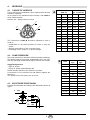
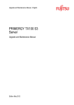
Istruzioni per installazione, uso e manutenzione Installation, use and maintenance instructions I Bruciatori di nafta GB Heavy oil burners CODICE CODE MODELLO - MODELL MODELE - MODEL TIPO - TYP TYPE 3439345 PRESS 450 T/N 469 M1 3439346 PRESS 450 T/N 469 M1 3439347 PRESS 450 T/N 469 M1 3439348 PRESS 450 T/N 469 M1 2915845 (7) - 06/2012 INDICE 1. 1.1 DESCRIZIONE DEL BRUCIATORE . . . . . . 1 Materiale a corredo. . . . . . . . . . . . . . . . . . . . . 1 2. 2.1 2.2 2.3 2.4 DATI TECNICI . . . . . . . . . . . . . . . . . . . . . . 2 Dati tecnici . . . . . . . . . . . . . . . . . . . . . . . . . . . 2 Dati elettrici . . . . . . . . . . . . . . . . . . . . . . . . . . . 2 Dimensioni . . . . . . . . . . . . . . . . . . . . . . . . . . . 4 Campo di lavoro . . . . . . . . . . . . . . . . . . . . . . . 4 3. 3.1 3.2 3.3 INSTALLAZIONE . . . . . . . . . . . . . . . . . . . . 5 Impianti alimentazione olio combustibile . . . . 5 Impianto elettrico . . . . . . . . . . . . . . . . . . . . . . 6 Collegamenti elettrici . . . . . . . . . . . . . . . . . . . 8 1. 4. FUNZIONAMENTO . . . . . . . . . . . . . . . . . . 9 4.1 4.2 4.3 4.4 4.5 4.6 4.7 4.8 4.9 4.10 Scelta degli ugelli . . . . . . . . . . . . . . . . . . . . . 9 Pressione della pompa . . . . . . . . . . . . . . . . . 9 Posicionamiento electrodos . . . . . . . . . . . . . 9 Regolazione testa di combustione . . . . . . . 10 Regolazione serrande . . . . . . . . . . . . . . . . . 10 Regolazione temperatura di polverizzazione 11 Programma di avviamento . . . . . . . . . . . . . 12 Funzionamento tristadio . . . . . . . . . . . . . . . 12 Diagnostica programma di avviamento . . . . 13 Diagnostica mal funzionamento . . . . . . . . . 13 DESCRIZIONE DEL BRUCIATORE Bruciatore di nafta con funzionamento monostadio, bistadio, tristadio. O Il bruciatore risponde al grado di protezione IP 40 secondo EN 60529. O Bruciatore con marcatura CE in conformità alle Direttive CEE: CEM 2004/108/CE, Bassa Tensione 2006/95/CE e Macchine 2006/42/CE. Fig. 1 D2802 1 2 3 4 5 6 7 8 9 10 - 1.1 Raccordo di aspirazione Raccordo di ritorno Motorino apriserranda Regolatore pressione pompa Attacco manometro Attacco vacuometro Termostato di minima Quadro comandi elettrici Passacavi Pulsante di sblocco apparecchiatura con segnalazione di blocco - Termostato di regolazione Vite regolazione testa di combustione Morsettiera Trasformatore d’accensione Filtro Gruppo valvole Manometro Segnalazioni luminose Commutatore Termostato di massima Temporizzatore MATERIALE A CORREDO Tubi flessibili . . . . . . . . . . . . . Passacavi . . . . . . . . . . . . . . . Schermo per flangia . . . . . . . Prolunghe (solo testa lunga) 5845 11 12 13 14 15 16 17 18 19 20 21 . . . . . . . . . . . . . . . . . . . . . . . . . . . . . . . . . . . . . . . . . . . . N° 2 N° 7 N° 1 N° 2 Nipples . . Viti . . . . . Ugelli . . . Avviatore 1 I . . . . . . . . . . . . . . . . . . . . . . . . . . . . . . . . . . . . . . . . . . . . . . . . . . . . . . . . . . . . . . . . . . . . . . . . . . . . . . . . . . . . . . . . . . . . . . . . N° 2 N° 4 N° 3 N° 1 2. DATI TECNICI 2.1 DATI TECNICI TIPO 469 M1 Potenza termica - Portata 855 ÷ 5130 kW Combustibile Olio viscosità max. a 50° C 50 mm2/s con kit fino a 500 mm2/s Pompa 690 kg/h a 25 bar – 75 ÷ 450 kg/h (vedi tabelle seguenti) (7° E) (65° E) 2.2 DATI ELETTRICI MOTORE IE1 Codice 3439345 - 3439346 Trifase, 230 V ± 10% senza neutro Alimentazione elettrica Motore (con avviatore ) rpm kW V A ~ 50Hz 2920 15 230 - 400 50,2 - 29 Trasformatore d’accensione Primario 2 A Riscaldatori 19,6 kW Potenza elettrica assorbita 37 kW – 3439347 - 3439348 Trifase, 400 V ± 10% con neutro ~ 50Hz 2920 15 400 - 690 27,3 - 15,8 Secondario 2 x 6,5 kV – 35 mA MOTORE IE2 Codice 3439345 - 3439346 Trifase, 230 V ± 10% senza neutro Alimentazione elettrica Motore (con avviatore ) rpm kW V A 2920 15 230 - 400 46,8 - 27 Trasformatore d’accensione Primario 2 A Riscaldatori 19,6 kW Potenza elettrica assorbita 37 kW 5845 ~ 50Hz 2 – 3439347 - 3439348 Trifase, 400 V ± 10% con neutro ~ 50Hz 2920 15 400 - 690 26,6 - 15,4 Secondario 2 x 6,5 kV – 35 mA I FUNZIONAMENTO E POTENZA DEL BRUCIATORE Potenza termica - Portata Minima MONOSTADIO Massima kW kg/h kW kg/h 1° ugello: stadio solo di accensione 855 75 1710 150 1° + 2° ugello: stadio di passaggio 1710 150 3420 300 1° + 2° + 3° ugello: stadio di funzionamento 2560 225 5130 450 Potenza termica - Portata Minima BISTADIO Massima kW kg/h kW kg/h 1° ugello: stadio solo di accensione 855 75 1710 150 1° + 2° ugello: 1° stadio di funzionamento 1710 150 3420 300 1° + 2° + 3° ugello: 2° stadio di funzionamento 2560 225 5130 450 Potenza termica - Portata Minima TRISTADIO Massima kW kg/h kW kg/h 1° ugello: 1° stadio di funzionamento 855 75 1710 150 1° + 2° ugello: 2° stadio di funzionamento 1710 150 3420 300 1° + 2 °+ 3° ugello: 3° stadio di funzionamento 2560 225 5130 450 ACCESSORI KIT PROTEZIONE CONTRO I RADIODISTURBI: Cod. 3010386 In caso di installazione del bruciatore in ambienti particolari soggetti a radiodisturbi (emissione di segnali oltre 10 V/m) a causa della presenza di INVERTER o in applicazioni dove le lunghezze dei collegamenti del termostato superano i 20 metri, è disponibile un kit di protezione come interfaccia tra l’apparecchiatura e il bruciatore. 5845 3 I 2.3 DIMENSIONI Bruciatore 305 435 565 * 950 525 ø 336 1090 128 * 508 D2776 Ottenibile con distanziale da chiedere a parte. Foratura piastra caldaia 310 350 310 SPORGENZA TESTA DI COMBUSTIONE Per la sporgenza della testa di combustione seguire le indicazioni fornite dal costruttore della caldaia. Per caldaie con cassa fumo anteriore eseguire una opportuna protezione in materiale refrattario sulla parte della testa sporgente in camera di combustione. M20 D2777 2.4 CAMPO DI LAVORO (3 ugelli funzionanti) Pressione in camera di combustione – mbar D2803 Campo di lavoro: limite di sicurezza kg/h kW Potenzialità bruciatore Quando il bruciatore funziona con un solo ugello, oppure con due, le condizioni di pressurizzazione sono più favorevoli e non pongono problemi. 5845 4 I 3. INSTALLAZIONE 3.1 IMPIANTI ALIMENTAZIONE OLIO COMBUSTIBILE IMPIANTO AD ANELLO Per olio denso con viscosità fino a 50°E / 50°C. D2734 1 - Cisterna (riscaldata per olio denso) 2 - Filtro (con resistenza per olio > 7°E / 50°C) 3 - Pompa di trasferimento 4 - Manometro di controllo 5 - Saracinesche per esclusione bruciatore (accoppiate) 6 - Bruciatore (con kit per olio denso cod. 3000721) 7 - Regolatore di pressione 8 - Filtro (con resistenza per olio > 7°E / 50°C) 9 - Pompa bruciatore NOTE IMPORTANTI - Per agevolare il flusso di combustibile tutte le tubazioni devono essere opportunamente dimensionate, coibentate e riscaldate (elettricamente o tramite vapore o acqua calda). - La pompa di trasferimento dovrà avere una portata almeno doppia di quella della pompa del bruciatore. Per più bruciatori alimentati dallo stesso anello la pompa di trasferimento dovrà avere una portata circa il 30% in più della somma delle portate dei singoli bruciatori. - Per l’avviamento: a bruciatore escluso tramite le saracinesche (5), far circolare combustibile nell’anello di alimentazione. Una volta raggiunta una circolazione a regime, aprire le saracinesche ed alimentare regolarmente il bruciatore. IMPIANTO PER GRAVITÀ Solo per olio leggero con viscosità max. 7°E / 50°C. H max. 10m Innesco pompa: allentare il tappo dall’attacco vacuometro (6, fig. 1) ed attendere la fuoriuscita del combustibile. H: Dislivello L: Lunghezza del tubo di aspirazione L metri H metri ø 1 1/4” ø 1 1/2” 0 5 10 0,5 8 15 1 11 20 1,5 14 25 2 17 30 D2735 Attenzione: accertarsi, prima di mettere in funzionamento il bruciatore, che il tubo di ritorno non abbia occlusioni. Un eventuale impedimento provocherebbe la rottura dell’organo di tenuta della pompa. 5845 5 I 3.2 IMPIANTO ELETTRICO DEL BRUCIATORE VERSIONE AD AVVIAMENTO STELLA - TRIANGOLO (eseguito in fabbrica) D2953 Nero Blu SCHEMA COMMUTATORE Marrone COLLEGAMENTI SONDA AL TERMOREGOLATORE D2738 D2737 CR CO FR L1 L2 L3 MB MV RMO S SM 5845 Contattore preriscaldatore Commutatore Fotoresistenza Segnalazioni di 1° stadio Segnalazioni di 2° stadio Segnalazioni di 3° stadio Morsettiera bruciatore Motore ventilatore Apparecchiatura elettrica Serbatoio preriscaldatore Servomotore SO TA TB TE Tm TM TP V1 V2 V3 VS 6 I Sonda PT100 Trasformatore d’accensione Terra bruciatore Termoregolatore Termostato min. Termostato max. Temporizzatore Valvola 1° stadio Valvola 2° stadio Valvola 3° stadio Valvola di sicurezza AVVIATORE STELLA - TRIANGOLO D2049 Fusibili circuito di potenza Fusibili circuito di comando Relé termico: tarare a 16,7A per 400V tarare a 29A per 230V KL1 Contattore di linea KS1 Contattore di stella KT Temporizzatore (tarare a 10 sec.) KT1 Contattore di triangolo MA Morsettiera Q1 Sezionatore con blocco porta F1 F2 F3 5845 7 I 3.3 COLLEGAMENTI ELETTRICI ALLA MORSETTIERA VERSIONE AD AVVIAMENTO STELLA - TRIANGOLO (a cura dell’installatore) ~ ~ D2625 A A gG/gL B mm2 C mm2 D mm2 H H1 IN MA MB PS Segnalazione di blocco a distanza Segnalazione di blocco motore Acceso-spento manuale (facoltativo) Morsettiera avviatore Morsettiera bruciatore Pulsante di sblocco 230V 63 10 6 6 400V 50 6 4 4 Allarme alta temperatura olio Telecomando di limite Telecomando di sicurezza Termostato di 2° stadio Termostato di 3° stadio SA TL TS T2 T3 NOTE: Verificare il blocco oscurando la fotoresistenza, dopo aver tolto il coperchio della mensola. ATTENZIONE ALTA TENSIONE. Questo modello lascia la fabbrica previsto per alimentazione 400V. Se l’alimentazione é 230V, cambiare il collegamento del serbatoio (da stella a triangolo). NOTA Negl’impianti in cui le lunghezze dei collegamenti dei termostati siano superiori a 20 metri, oppure l’ambiente in cui si trova il bruciatore sia particolarmente disturbato da interferenze elettromagnetiche (maggiore 10 v/m) è necessario inserire il kit interfaccia-relè codice 3010386. 5845 8 I 4. FUNZIONAMENTO 4.1 SCELTA DEGLI UGELLI Stabilire per prima la massima portata desiderata con tutti e tre gli ugelli funzionanti. Sulla base della portata massima scegliere, nella tabella A, la terna di ugelli necessaria. Ugelli: 60° - Pressione pompa: 25 bar. 1° 3° 2° D2741 Se si desidera: - modificare la pressione della pompa per variare la portata, - comporre diversamente la terna degli ugelli, - conoscere la portata in 1° e 2° stadio, usare la tabella B. 4.2 Ugello GPH 60° A 1° 2° Portata totale kg/h 1°+2°+3° 3° 25 bar 28 bar 11,00 11,00 11,00 207 291 12,00 12,00 12,00 228 240 13,00 13,00 13,00 246 261 13,80 13,80 13,80 258 279 14,00 14,00 14,00 264 282 15,00 15,00 15,00 285 300 15,30 15,30 15,30 291 306 16,00 16,00 16,00 300 321 17,00 17,00 17,00 321 342 18,00 18,00 18,00 339 363 19,00 19,00 19,00 357 384 20,00 20,00 20,00 378 405 21,50 21,50 21,50 405 432 24,00 24,00 24,00 453 – PRESSIONE DELLA POMPA La pressione della pompa è riferita a tre ugelli funzionanti. Quando funzionano due ugelli, e più ancora un ugello solo, la pressione sale automaticamente. GPH 25 bar kg/h 28 bar kg/h Pressione consigliata: - Olio fluido: 25 bar - Olio denso: 28 bar (vedi kit di trasformazione) 12,00 76 80 13,00 82 87 Le portate degli ugelli indicate in tabella sono nominali. La portata reale può variare rispetto a quella nominale del ±5%. La pompa lascia la fabbrica tarata a 25 bar. 13,80 86 93 14,00 88 94 15,00 95 100 15,30 97 102 16,00 100 107 17,00 107 114 18,00 113 121 19,00 119 128 20,00 126 135 21,50 135 144 24,00 151 – 4.3 POSIZIONAMENTO ELETTRODI Posizionare gli elettrodi rispettando le dimensioni indicate in figura. 4 mm D11353 1 5 mm 5845 9 I B 4.4 REGOLAZIONE TESTA DI COMBUSTIONE C kg/h D2808 ELIC AS EN Z AA N EL LO Infine, sulla base della portata massima ricavare, nel diagramma C, la regolazione della testa di combustione. La regolazione si effettua ruotando la vite A, fino a che la tacca, rilevata dal diagramma, collima con il piano della bussola B. B D2809 ANELLO 4.5 Tacca 6 ELICA A EL REGOLAZIONI SERRANDE IC A N CO A L NE LO La regolazione delle serrande va adattata di volta in volta alla portata degli ugelli e alla pressurizzazione della camera di combustione. La figura 2 mostra come sono disposte le serrande dell’aria. La figura 3 mostra come sono disposte le camme all’interno del motorino. N° tacche Fig. 2 REGOLAZIONE 1° STADIO: va effettuata manualmente. REGOLAZIONE 2°- 3° STADIO: vanno regolate attraverso le camme del motorino con l’ausilio di un piccolo cacciavite. Il motorino segue automaticamente ogni spostamento delle camme. Regolazione camme comando serrande Camma 0: non necessita di alcuna regolazione, viene regolata in fabbrica nella posizione di serrande chiuse. Camma ST2: regola la posizione delle serrande in 2° stadio. Agendo sulla camma ST2 si muove tutto il gruppo A (fig. 3). Camma ST3: regola la posizione delle serrande in 3° stadio. Agendo sulla camma ST3 si muove tutto il gruppo B (fig. 3). D2774 Indice serrande 2° - 3° stadio Motorino apriserrande 2° - 3° stadio Serranda 1° stadio Fig. 3 Regolazioni camme comando valvole 1a valvola: viene comandata dall’apparecchiatura. 2a valvola: viene comandata dalla camma MV2. Nel caso si desideri anticipare l’apertura della valvola prima che la serranda giunga nella posizione di 2° stadio, agire sulla camma MV2. viene comandata dalla camma fissa adia3a valvola: cente alla ST3. NB: Le camme con le viti sigillate non vanno mai regolate. 5845 10 I 4.6 REGOLAZIONE TEMPERATURA DI POLVERIZZAZIONE Termostati di regolazione - di minima - di massima Fig. 4 mm2/s °E Esempio: un olio combustibile 7 °E a 50 °C va preriscaldato a 110 °C. °C Temperatura di polverizzazione Fig. 5 kg/h D2812 Viscosità a 50° C IMPORTANTE La temperatura impostata sul termostato corrisponde alla temperatura del fluido, verificare comunque attraverso il termometro la corrispondenza dopo alcuni minuti di funzionamento. Il led acceso indica il regolare inserimento delle resistenze. Il preriscaldatore montato sul bruciatore fornisce un ýt di 75°C a 450 kg/h (fig. 5). L’eventuale ýt mancante deve essere fornito da un preriscaldatore ausiliario. D2811 Viscosità a 50° C Il termostato di regolazione elettronico, attraverso una sonda PT 100 immersa nel collettore di mandata dell’olio combustibile regola la temperatura di polverizzazione. Per una corretta polverizzazione vedere figura 4. Il termostato di minima (fig. 6), oltre ad arrestare il bruciatore nel caso la temperatura del combustibile scenda sotto un valore critico per una buona combustione, da il consenso alla fase di avviamento del bruciatore. (Viene tarato in fabbrica a circa 80 °C la sua regolazione è accessibile togliendo il coperchio del preriscaldatore e la relativa piastra). °C Il termostato di massima (fig. 6), disinserisce le resistenze quando, a causa di guasto del termostato di regolazione, si registra un sensibile aumento della temperatura nel preriscaldatore, l’eventuale segnalazione di allarme (alta temperatura) è prelevabile dalla morsettiera del bruciatore. (Viene tarato in fabbrica a circa 180 °C). ýt Preriscaldatore - Portata Fig. 6 Termometro Sostituzione dei termostati di minima e di massima Riposizionare le sonde dei nuovi termostati, dopo aver allentato le viti di fissaggio del pacco tavolette, avendo cura che la sonda sia a contatto delle tubazioni e della resistenza come illustrato in figura 7. Valgono le stesse precauzioni nel caso di sostituzione delle resistenze a contatto delle sonde dei termostati. Nel caso di malfunzionamento, verificare con un ohmetro la continuità delle resistenze poste a contatto delle sonde di temperatura (valore circa 35 Ohm). Sostituzione della sonda PT 100 nel collettore di mandata Inserire dado e bicono (dati a corredo della sonda) nella nuova termoresistenza ed introdurla nel raccordo del collettore per circa 40 mm, stringere solidamente. La parte esterna può essere piegata a seconda delle necessità (la termoresistenza non si danneggia). Termostato min. Termostato max. D2747 Preriscaldatore Scarico impurità 11 Tubazioni tavoletta Fig. 7 Tavoletta Resistenza D2751 5845 Sonda termostato regolazione I Sonda del termostato 4.7 PROGRAMMA DI AVVIAMENTO Normale Blocco per mancata accensione Termostato Motore Trasf. d’accensione Prelavaggio Valvola 1a fiamma Valvola 2a fiamma Valvola 3a fiamma Spia di blocco D2848 Taratura di fabbrica: 20 s. Questo tempo determina la temperatura della nafta all’accensione; può essere regolato, in funzione della viscosità del combustibile, dal temporizzatore 21) (Fig. 1). Il diagramma a lato indica le tarature consigliate. D3211 tx (s) (tx) tx max = 60 s Blocco motore É provocato dal relè termico salvamotore in caso di sovraccarico o di mancanza di fase. Viscosità a 50°C (°E) NB.: Pulire periodicamente il filtro del serbatoio preriscaldatore. 4.8 FUNZIONAMENTO TRISTADIO 3° stadio max. 2° stadio 1° stadio 0 D2749 5845 12 I 4.9 DIAGNOSTICA PROGRAMMA DI AVVIAMENTO Durante il programma di avviamento, le indicazioni sono esplicate nella seguente tabella: TABELLA CODICE COLORE Sequenze Codice colore Preventilazione Fase di accensione Funzionamento con fiamma ok Funzionamento con fiamma debole Alimentazione elettrica inferiore a ~ 170V Blocco Luce estranea Legenda: 4.10 Spento Giallo Verde Rosso DIAGNOSTICA MAL FUNZIONAMENTO L’apparecchiatura in dotazione ha una sua funzione diagnostica attraverso la quale è possibile facilmente individuare le possibili cause di mal funzionamento (segnalazione: LED ROSSO). Per utilizzare tale funzione, bisogna aspettare almeno dieci secondi dall’istante di messa in sicurezza dell’apparecchiatura e premere il pulsante di sblocco per un tempo minimo di tre secondi. Rilasciato il pulsante, il LED ROSSO comincerà a lampeggiare, come illustrato nella seguente figura. LED ROSSO acceso aspettare per almeno 10 s premere pulsante per > 3 s segnale Intervallo 3s segnale Gli impulsi del LED costituiscono un segnale intervallato da 3 secondi circa. Il numero degli impulsi darà le informazioni sui possibili guasti, secondo la seguente tabella: SEGNALE 2 lampeggi 3 lampeggi 4 lampeggi CAUSA PROBABILE Non viene rilevato un segnale stabile di fiamma nel tempo di sicurezza: – guasto alla fotoresistenza; – guasto alla valvola olio; – guasto al trasformatore di accensione – bruciatore non regolato. – Non utilizzato. – Luce presente in camera prima dell’accensione. 7 lampeggi Sparizione della fiamma durante il funzionamento: – bruciatore non regolato; – guasto alla valvola olio. 8 lampeggi – Guasto termostato di consenso olio; – Interruzione resistenze riscaldanti. 10 lampeggi – Errore di collegamento o guasto interno; – Presenza disturbi elettromagnetici: utilizzare kit protezione contro i radiodisturbi 5845 13 I INDEX 1. 1.1 BURNER DESCRIPTION . . . . . . . . . . . . . . 1 Burner equipment . . . . . . . . . . . . . . . . . . . . . . 1 2. 2.1 2.2 2.3 2.4 TECHNICAL DATA . . . . . . . . . . . . . . . . . . 2 Technical data . . . . . . . . . . . . . . . . . . . . . . . . 2 Electrical data . . . . . . . . . . . . . . . . . . . . . . . . . 2 Overall dimensions . . . . . . . . . . . . . . . . . . . . . 4 Working field . . . . . . . . . . . . . . . . . . . . . . . . . . 4 3. 3.1 3.2 3.3 INSTALLATION . . . . . . . . . . . . . . . . . . . . . 5 Heavy oil supply line . . . . . . . . . . . . . . . . . . . . 5 Electrical system. . . . . . . . . . . . . . . . . . . . . . . 6 Electrical connections . . . . . . . . . . . . . . . . . . . 8 1. BURNER DESCRIPTION 4. 4.1 4.2 4.3 4.4 4.5 4.6 4.7 4.8 4.9 4.10 WORKING . . . . . . . . . . . . . . . . . . . . . . . . 9 Choice of nozzles . . . . . . . . . . . . . . . . . . . . . 9 Pump pressure . . . . . . . . . . . . . . . . . . . . . . . 9 Electrode positioning . . . . . . . . . . . . . . . . . . . 9 Combustion head setting . . . . . . . . . . . . . . 10 Air shutters adjustments . . . . . . . . . . . . . . . 10 Spray temperature adjustment . . . . . . . . . . 11 Burner start-up cycle . . . . . . . . . . . . . . . . . 12 Three stage operation . . . . . . . . . . . . . . . . 12 Burner start-up cycle diagnostics . . . . . . . . 13 Operating fault diagnostics . . . . . . . . . . . . . 13 One, two, third stage heavy oil burner. O The burner meets protection level of IP 40, EN 60529. O Burner with CE marking in conformity with EEC Directives: EMC 2004/108/EC, Low Voltage 2006/95/EC and Machines 2006/42/EC. Fig. 1 1 2 3 4 5 6 7 8 9 10 11 1.1 - Suction line Return line Air shutter opening motor Pump pressure adjustment screw Manometer plug Vacuometer plug Low limit thermostat Electric board Cable clamps Control box reset push-button and lock-out lamp Adjustment thermostat - Regulating bush for combustion head Wiring terminal board Ignition transformer Filter Valves group Manometer Lamp Commutator High limit thermostat Timer BURNER EQUIPMENT Flexible tubes . . . . . . . . . . . Cable clamps . . . . . . . . . . . Gasket for flange. . . . . . . . . Extensions (only long head). 5845 12 13 14 15 16 17 18 19 20 21 . . . . . . . . . . . . . . . . . . . . . . . . . . . . . . . . . . . . . . . . . . . . No. 2 No. 7 No. 1 No. 2 Nipples . Screws . Nozzles Starter . 1 GB . . . . . . . . . . . . . . . . . . . . . . . . . . . . . . . . . . . . . . . . . . . . . . . . . . . . . . . . . . . . . . . . . . . . . . . . . . . . . . . . . . . . . . . . . . . . . . . . No. 2 No. 4 No. 3 No. 1 2. TECHNICAL DATA 2.1 TECHNICAL DATA TYPE 469 M1 Thermal power - Output 855 ÷ 5130 kW Fuel Oil with max. viscosity at 50° C 50 mm2/s (7° E) for oil up to 500 mm2/s (65° E)with kit Pump 690 kg/h at 25 bar – 75 ÷ 450 kg/h (see tables below) 2.2 ELECTRICAL DATA MOTOR IE1 Code 3439345 - 3439346 Three-phase, 230 V ± 10% ~ 50Hz without neutral Electrical supply Motor (with starter ) rpm kW V A 2920 15 230 - 400 50.2 - 29 Ignition transformer Primary 2 A Heaters 19.6 kW Absorbed electrical power 37 kW – 3439347 - 3439348 Three-phase, 400 V ± 10% with neutral ~ 50Hz 2920 15 400 - 690 27.3 - 15.8 Secondary 2 x 6.5 kV – 35 mA MOTOR IE2 Code 3439345 - 3439346 Three-phase, 230 V ± 10% ~ 50Hz without neutral Electrical supply Motor (with starter ) rpm kW V A 2920 15 230 - 400 46.8 - 27 Ignition transformer Primary 2 A Heaters 19.6 kW Absorbed electrical power 37 kW 5845 2 – 3439347 - 3439348 Three-phase, 400 V ± 10% with neutral ~ 50Hz 2920 15 400 - 690 26.6 - 15.4 Secondary 2 x 6.5 kV – 35 mA GB OPERATION AND EFFICIENCY OF THE BURNER Thermal power - Output st Minimum 1 STAGE Maximum kW kg/h kW kg/h 1st nozzle: ignition phase 855 75 1710 150 1st+2nd nozzle: intermediate phase 1710 150 3420 300 2560 225 5130 450 1st+2nd+3rd nozzle: operation phase Thermal power - Output 2nd Minimum STAGE Maximum kW kg/h kW kg/h 1st nozzle: ignition phase 855 75 1710 150 1st+2nd nozzle: 1st stage of operation 1710 150 3420 300 1st+2nd+3rd nozzle: 2nd stage of operation 2560 225 5130 450 Thermal power - Output 3rd Minimum STAGE Maximum kW kg/h kW kg/h 1st nozzle: 1st stage of operation 855 75 1710 150 1st+2nd nozzle: 2nd stage of operation 1710 150 3420 300 1st+2nd+3rd nozzle: 3rd stage of operation 2560 225 5130 450 ACCESSOIRES RADIO DISTURBANCE PROTECTION KIT: Code 3010386 If the burner is installed in places particularly subject to radio disturbance (emission of signals exceeding 10 V/m) owing to the presence of an INVERTER, or in applications where the length of the thermostat connections exceeds 20 metres, a protection kit is available as an interface between the control box and the burner. 5845 3 GB 2.3 OVERALL DIMENSIONS Burner 305 435 565 * 950 525 ø 336 1090 128 508 * D2776 It is possible with a spacer, upon request. Boiler front plate drilling COMBUSTION HEAD PROJECTION 310 350 310 For the combustion head projection carefully follow the boiler manufacturer indications. A proper protection with refractory material on the combustion head projecting into the combustion chamber shall be made, when boilers with frontal smoke box are used. M20 D2777 2.4 WORKING FIELD (3 nozzles in operation) Pressure in combustion chamber – mbar D2803 Working field: limit safety kg/h kW Thermal power When the burner operates with only one or two nozzles, the pressurization conditions are improved and no problems arise. 5845 4 GB 3. INSTALLATION 3.1 HEAVY OIL SUPPLY LINE RING SUPPLY LINE For heavy oil with viscosity up to 50°E/50°C. D2734 1 - Tank (heated for heavy oil) 2 - Filter (with resistance for oil > 7°E/50°C) 3 - Forwarding pump 4 - Control manometer 5 - Shutter valves (in couple) excluding the burner 6 - Burner (provided with kit for heavy oil code no. 3000721) 7 - Pressure adjuster 8 - Filter (with resistance for oil > 7°E/50°C) 9 - Burner pump WARNING - The oil could easily flow through the pipes if those are properly seized, protected and heated (by electricity, steam or hot water). - The forwarding pump capacity should be all the least double of that of the burner pump. If several burners are supplied through the same ring supply line, the forwarding pump should have a capacity of approx. 30% more than the sum of the single burners outputs. - For starting-up: after excluding the burner by the shutter valves (5) let the oil flow into the supply ring up to reach the required circulation; after than open the valves and supply normally the burner. GRAVITY SUPPLY LINE Only for oil with max. viscosity up to 7°E/50°C. H max. 10m Pump priming: loose the tap of the vacuometer plug (6, fig. 1) and wait for the oil flow. H: Difference in the pipes height L: Total length of the suction tube H meters 0 0.5 1 1.5 2 L meters ø 1 1/4” ø 1 1/2” 5 10 8 15 11 20 14 25 17 30 D2735 Attention: before placing the burner in operation, ensure that the return line is open. Any obstruction may damage the pump seal. 5845 5 GB 3.2 ELECTRICAL SYSTEM STAR-TRIANGLE START-UP (carried out by the factory) D2953 COMMUTATOR Black Blue Brown PRE-HEATER CONNECTION PROBE TO ELECTRONIC THERMOSTAT D2738 D2737 CR CO FR L1 L2 L3 MB MV RMO S SM 5845 Resistor contact maker Commutator Photoresistence Lamps for 1st stage Lamps for 2nd stage Lamps for 3rd stage Burner terminal strip Fan motor Control box Pre-heater tank Air-damper actuator SO TA TB TE Tm TM TP V1 V2 V3 VS 6 GB Probe PT100 Ignition transformer Burner earth Electronic thermostat Minimal thermostat Maximal thermostat Timer Oil valves for 1st stage Oil valves for 2nd stage Oil valves for 3rd stage Safety valve STAR-DELTA STARTER D2049 Power line fuses Control devices fuse Thermal relay to be set at 16.7A for 400V or at 29A for 230V KL1 Line contact maker KS1 Star contact maker KT Timer relay for switching from star to delta (factory calibration at 10s) KT1 Delta contact maker MA Starter terminal strip Q1 Disconnecting switch with interlock F1 F2 F3 5845 7 GB 3.3 ELECTRICAL CONNECTIONS TO THE BURNER TERMINAL STRIP STAR-TIRANGLE START-UP (to be carried out by the installer) ~ ~ D2625 A A gG/gL B mm2 C mm2 D mm2 H H1 IN MA MB PS Remote lock-out signal Motor trip signal Optional switch on-off burne Start-up terminal strip Burner terminal strip Reset push - button SA TL TS T2 T3 230V 63 10 6 6 400V 50 6 4 4 High temperature oil alarm Limit control device system Safety control device system Load control system for 2nd stage Load control system for 3rd stage NOTE: Check the lock-out by darkening the photo-cell after removal of the cover. ATTENTION HIGH VOLTAGE. In case of supply 230V without neutral, connect the pre-heater thank through delta (the “star” connection is the original one, made for 400V). NOTE In systems where the run of wiring connecting the thermostat exceeds 20 metres in length, or in places where the burner is subject to particularly disturbing electromagnetic interference (over 10 v/m), you must insert the relay-interface kit item number 3010386. 5845 8 GB 4. WORKING 4.1 CHOICE OF NOZZLES First of all state the maximum output required with all three nozzles in operation. On the base of the maximum output choose, from table A, three related nozzles. Nozzles: 60° - Pump pressure: 25 bar. 1st 3rd 2nd D2741 The references of table B should be followed in case of need of: - modification of the pump pressure in order to vary the output, - diverse composition of the 3 nozzles group, - knowledge of the output in 1st and 2nd stage. 4.2 Suggested pressure: - Light oil: 25 bar - Heavy oil: 28 bar (transformation kit) Rated nozzles deliveries are listed on the table. A tolerance of ±5% concerns the real delivery against the rated one. The pump leaves the factory set at 25 bar. ELECTRODE POSITIONING Position the electrodes according to the dimensions shown in figure. 4 mm D11353 1 5 mm 5845 1st 2nd Total output kg/h 1st+2nd+3rd 3rd 25 bar 28 bar 11.00 11.00 11.00 207 291 12.00 12.00 12.00 228 240 13.00 13.00 13.00 246 261 13.80 13.80 13.80 258 279 14.00 14.00 14.00 264 282 15.00 15.00 15.00 285 300 15.30 15.30 15.30 291 306 16.00 16.00 16.00 300 321 17.00 17.00 17.00 321 342 18.00 18.00 18.00 339 363 19.00 19.00 19.00 357 384 20.00 20.00 20.00 378 405 21.50 21.50 21.50 405 432 24.00 24.00 24.00 453 – PUMP PRESSURE The pump pressure is referred to all three nozzles operating. The pump pressure increases automatically when two nozzles are operating and becomes higher with only one nozzle. 4.3 Nozzles GPH 60° A 9 GB B GPH 25 bar kg/h 28 bar kg/h 12.00 76 80 13.00 82 87 13.80 86 93 14.00 88 94 15.00 95 100 15.30 97 102 16.00 100 107 17.00 107 114 18.00 113 121 19.00 119 128 20.00 126 135 21.50 135 144 24.00 151 – 4.4 COMBUSTION HEAD ADJUSTMENT kg/h D2808 1 On the base of the maximum delivery detect, from diagramm C, the combustion head adjustment. The adjustment should be made by turning the screw A till the set-point (see diagram) is on the line with the washer B. C B D2809 Set-point 6 DIFFUSER DISC 2 DAMPER RING 4.5 A AIR SHUTTERS ADJUSTMENTS The adjustment of the air shutters shall be set each time, with reference to the nozzles deliveries and the combustion chamber pressurization. Fig. 2 shows the positioning of the air shutters. Fig. 3 shows the positioning of the cams of the motor. 1st STAGE ADJUSTMENT: it must carry out manually. Set-point 1 Diffuser disc without damper ring 2 Diffuser disc with damper ring Fig. 2 2nd - 3rd STAGE ADJUSTMENT: its must carry out by the motor cams with a little screwdriver. The motor follows each moving of the cams automaticly. Cams command air shutters adjustments Cam 0: adjustment not necessary. Positioned by the factory on the close shutters. Cam ST2: for 2nd stage air shutters adjustment. All group A) moves by acting on cam ST2, (fig. 3). Cam ST3: for 3rd stage air shutters adjustment. All group B) moves by acting on cam ST3, (fig. 3). Cams command valves adjustment 1st valve: controlled by the control box. 2nd valve: controlled by the cam MV2. Act on the cam MV2 to open the valve before the shutter reach the 2nd stage position. rd 3 valve: controlled by the fixed cam next the cam ST3. D2774 Air shutter position 2nd and 3rd stage 2nd and 3rd stage air shutter motor Sector A 1st stage air shutter Fig. 3 NOTE: Never adjust the cams with sealed screws. 5845 10 GB 4.6 SPRAY TEMPERATURE ADJUSTMENT Thermostat for adjustment - maximum value minimum value Fig. 4 mm2/s °E Viscosity at 50° C Electronic adjustment thermostat by means of information relayed from a PT100 probe immersed in the oil in the delivery manifold, the thermostat adjusts spray temperature. The correct conditions for fuel spray are shown in figure 4. Example: fuel oil with 7 °E viscosity at 50 °C is pre-heated to approximately 110 °C. Important: although the temperature set on the thermostat should correspond to the temperature of the fluid, it is good practice to check that the thermometer shows the correct reading once the unit has been in operation for a few minutes. The LED will illuminate to indicate that the heating resistances are working properly. °C Spray temperature Fig. 5 Minimum temperature thermostat (fig. 6), in addition to shutting down the burner if the fuel temperature should fall below the critical value for correct combustion, this thermostat also provides a permissive signal at the time of burner start-up. (Factory set at approximately 80°C, adjustable by removing the pre-heater cover and relative plate). Renewing the minimum and maximum temperature thermostats. Reposition the probes of the new thermostat, after having first loosened the plate pack securing screws. Make sure that the probe is touching the resistance and the plate pack as shown in the figure 7. The same precautions should be taken when renewing the resistances in contact with the thermostat probes. If the pre-heater should malfunction, use an ohmmeter to check that the resistances located in contact with the temperature probes are not burnt out (reading of approximately 35 Ohm). D2812 °C ýt Pre-heater - delivery Fig. 6 Adjustment thermostat probe Thermometer Min. thermostat Max. thermostat D2747 Pre-heater Purge Tubes into aluminium plate Fig. 7 Aluminium plate Changing the PT100 probe in the oil delivery manifold. Fit the supplied nut and biconical collar on the new probe, insert a length of approximately 40mm in the manifold, and secure firmly into place. At this point, the section remaining outside the manifold can be bent as required, with no risk of damaging the resistance. Resistance D2751 5845 kg/h Viscosity at 50° C The pre-heater fitted to the burner supplies a t di 75°C at 450 kg/h (see fig. 5). If there is a t shortfall, this can be made up by an auxiliary pre-heater. Maximum temperature thermostat (fig. 6) this switches off the resistance when, because of failure of the adjustment thermostat, the temperature of the pre-heater increases to unacceptable levels; a “high temperature” alarm output is provided on the burner terminal strip. (Factory setting is approximately 180°C). D2811 11 GB Thermostat probe 4.7 BURNER START-UP CYCLE Normal Lock-out because no ignition Thermostat Motor Ignition transformer Pre-purge 1st flame valve 2nd flame valve 3rd flame valve Lock-out lamp D2848 Factory setting: 20 s. This time determines the heavy oil temperature at ignition. It can be adjusted, according to the fuel’s viscosity, by the timer 21) (Fig. 1). The adjacent diagram shows the suggested settings. D3211 tx (s) (tx) tx max = 60 s Motor lock-out It is caused by the over load relay when overload occurs or no current supply. Viscosity at 50°C (°E) NB.: Periodically clean the filter of the pre-heater tank. 4.8 THREE STAGE OPERATION 3rd stage max. 2nd stage 1st stage 0 D2749 5845 12 GB 4.9 BURNERS START-UP CYCLE DIAGNOSTICS During start-up, indication is according to the followin table: COLOUR CODE TABLE Sequences Colour code Pre-purging Ignition phase Operation, flame ok Operating with weak flame signal Electrical supply lower than ~ 170V Lock-out Extraneous light Off Key: Yellow Green Red 4.10 OPERATING FAULT DIAGNOSTICS The control box has a self-diagnostic system, which easily allows identifying the operating faults (RED LED signal). ITo use this function, wait at least ten seconds from the safety lock out, and then press the reset button for a minimum of 3 seconds. After releasing the button, the RED LED starts flashing as shown in the diagram below. RED LED on wait at least 10 s Press button for > 3 s Signal Interval 3s Signal The pulses of the LED constitute a signal spaced by approximately 3 seconds. The number of pulses will provide the information on the possible faults, according to the table below: SIGNAL 2 flashes 3 flashes 4 flashes PROBABLE CAUSE The flame does not stabilise at the end of the safety time: – faulty photocell; – faulty or soiled oil valves; – faulty ignition transformer – poor burner regulation. – Not used. – Light in the chamber before firing. 7 flashes Loss of flame during operations: – poor burner regulation; – faulty or soiled oil valves. 8 flashes – Faulty thermostat for oil permissive signal; – Heating resistances blown. 10 flashes – Wiring error or internal fault; – Presence of electromagnetic disturbance: use the radio disturbance protection kit 5845 13 GB RIELLO S.p.A. I-37045 Legnago (VR) Tel.: +39.0442.630111 http:// www.riello.it http:// www.rielloburners.com Con riserva di modifiche - Subject to modifications