1
PREMESSA
– Questo manuale fornisce le informazioni principali per
le procedure di normale intervento.
– Le informazioni e le illustrazioni che compongono questo manuale, sono aggiornate al momento della divulgazione del manuale stesso.
Prima di procedere nella consultazione controllare il
modello del veicolo e i relativi aggiornamenti nella sezione 9 “AGGIORNAMENTI”.
– Questa pubblicazione è indirizzata ai tecnici del settore; molte nozioni sono state volutamente omesse, perché giudicate superflue.
Per eventuali informazioni, interpellare il REPARTO
ASSISTENZA aprilia.
– Per ulteriori informazioni vedi il MANUALE D’OFFICINA MOTORE, N˚ 929 (D-I) / N˚ 930 (UK-E-F), il CATALOGO RICAMBI MOTORE, N˚ 919 e il CATALOGO
RICAMBI “CICLISTICA”, N˚ 650.
La ditta aprilia s.p.a. si riserva il diritto di apportare modifiche in qualsiasi momento ai propri modelli, fermo restando le caratteristiche essenziali qui descritte e illustrate.
I diritti di memorizzazione elettronica, di riproduzione e di
adattamento totale o parziale, con qualsiasi mezzo sono
riservati per tutti i Paesi.
La citazione di prodotti o servizi di terze parti è solo a scopo informativo e non costituisce nessun impegno.
aprilia s.p.a. non si assume la responsabilità riguardo le
prestazioni o l’uso di questi prodotti.
USO DEL MANUALE
◆
◆
NORME PER LA CONSULTAZIONE
– Se non espressamente descritto, il riassemblaggio dei gruppi segue in senso inverso le operazioni di smontaggio.
– Per ogni intervento sul motore consultare il manuale specifico: N˚ 929 (D-I) e N˚ 930 (UK-E-F).
– Consultare il libretto “USO E MANUTENZIONE” per
l’uso del veicolo e le normali operazioni di manutenzione.
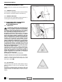
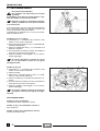
SIMBOLOGIA
Osservare scrupolosamente gli avvertimenti preceduti
dalle seguenti simbologie:
a
c
Norme e misure di sicurezza che proteggono
il pilota, l’operatore e altre persone da lesioni
o rischi gravi e/o danni al veicolo.
Indicazioni per facilitare lo svolgimento delle
operazioni. Informazioni tecniche.
★
Le operazioni precedute da questo simbolo
devono essere ripetute dal lato opposto del
veicolo.
INDICE GENERALE
INFORMAZIONI GENERALI
1
OPERAZIONI DI MANUTENZIONE
PERIODICA E DI MESSA A PUNTO
2
MOTORE
3
SISTEMA DI ALIMENTAZIONE
4
IMPIANTO DI RAFFREDDAMENTO
5
IMPIANTO ELETTRICO
6
CICLISTICA
7
INFORMAZIONI PER LE RIPARAZIONI
8
AGGIORNAMENTI
9
Prima edizione: settembre 1996
Ristampa: gennaio 1997
Prodotto e stampato da:
Studio Tecno Public
Viale del Progresso - 37038 Soave (VR) - Italia
Tel. 045 -76 11 911
Fax 045 -76 12 241
per conto di:
aprilia s.p.a.
via G. Galilei, 1 - 30033 Noale (VE)
Tel. 041 - 58 29 111
Fax 041 - 44 10 54
0 -1
PREMISA
INDICE GENERAL
1
INFORMACIONES GENERALES
2
OPERACIONES DE MANTENIMIENTO
PERIODICO Y DE PUESTA A PUNTO
3
MOTOR
4
SISTEMA DE ALIMENTACION
5
INSTALACION DE REFRIGERACION
6
INSTALACION ELECTRICA
7
PARTE CICLO
8
INFORMACIONES
PARA LAS REPARACIONES
9
ACTUALIZACIÓNES
Primera edición: septiembre 1996
Nueva edición: enero 1997
Producido e impreso por:
Studio Tecno Public
Viale del Progresso - 37038 Soave (VR) - Italia
Tel. 045 - 76 11 911
Fax 045 - 76 12 241
por parte de:
aprilia s.p.a.
via G. Galilei, 1 - 30033 Noale (VE)
Tel. 041 - 58 29 111
Fax 041 - 44 10 54
0 -2
– Este manual suministra las informaciones principales
para los procedimientos de intervención corriente.
– Las informaciones y las ilustraciones que forman parte
de este manual, están puestas al día en el momento
de la divulgación del manual mismo.
Antes de consultar el manual, controle el modelo del
vehículo y si acaso la parte puesta al día correspondiente, en la sección 9 “ACTUALIZACIÓN”.
– Esta publicación se dirige a los técnicos del sector, por
lo tanto se han omitido voluntariamente muchas opciones en cuanto las consideramos superfluas.
Para otras informaciones, llame al DEPARTAMENTO
ASISTENCIA aprilia s.p.a.
– Para otras informaciones véase el MANUAL DE TALLER MOTOR, N˚ 929 (D-I) / N˚ 930 (UK-E-F), el CATALOGO REPUESTOS MOTOR, N˚ 919 y el CATALOGO REPUESTOS "PARTE CICLO", N˚ 650.
La empresa aprilia s.p.a. se reserva el derecho de aportar modificaciones a sus modelos en cualquier momento,
guardando siempre las características esenciales descritas e ilustradas en este manual.
A todos los países se les reserva los derechos de memorización electrónica, de reproducción y de adaptación total y parcial, con cualquier medio.
El hecho de citar productos o servicios por cuenta ajena
tiene el solo fin de informar y no constituye ningún compromiso.
La empresa aprilia s.p.a. no se hace cargo de ninguna
responsabilidad en cuanto a las prestaciones o al uso de
estos productos.
USO DEL MANUAL
◆
NORMAS PARA LA CONSULTA
– De no estar expresamente descrito, hay que
realizar el reensamblaje de los grupos siguiendo en orden contrario las operaciones que se
han efectuado para el desmontaje.
– Para cada intervención sobre el motor, consulte el
manual específico: N˚ 929 (D-I) y N˚ 930 (UK-E-F).
– Consulte el manual "USO Y MANTENIMIENTO" en
cuanto al uso del vehículo y para las corrientes operaciones de mantenimiento.
◆
SIMBOLOS
Observe esmeradamente las advertencias precedidas
por los siguientes símbolos:
a
c
Normas y medidas de seguridad que protegen
al piloto, al operador u a otras personas de lesiones o riesgos graves y/o daños al vehículo.
Indicaciones para facilitar el desarrollo de las
operaciones. Informaciones técnicas.
★
Hay que repetir las operaciones que están
precedidas por este símbolo en el lado opuesto del vehículo.
FOREWORD
– This manual supplies the main information for normal
servicing procedures.
– The information and illustrations contained in this manual are updated to the moment of its publication.
Before consulting the manual, check the vehicle model
and the relevant updates in section 9 “UPDATES”.
– This publication is meant for professional mechanics,
therefore many notions have been intentionally omitted, as they were regarded as superfluous.
For any further information, contact aprilia s.p.a.
SERVICE DEPARTMENT.
– For any further information see the ENGINE SERVICE
MANUAL, No 929 (D-I) / No 930 (UK-E-F), the ENGINE SPARE PARTS CATALOGUE, No 919 and the
"CHASSIS PARTS" SPARE PARTS CATALOGUE, No
650.
aprilia s.p.a. reserves the right to modify its models at
any time, without prejudice to the main characteristics
here described.
TABLE OF CONTENTS
GENERAL INFORMATION
1
SERVICE AND SETTING UP
2
ENGINE
3
FUEL SUPPLY SYSTEM
4
COOLING SYSTEM
5
ELECTRICAL SYSTEM
6
CHASSIS PARTS
7
REPAIR INFORMATION
8
UPDATES
9
All rights as to electronic storage, reproduction and total
or partial adaptation, with any means, are reserved for all
Countries.
The mention to products or services supplied by third parties is made only for information purposes and is not
binding in any case.
aprilia s.p.a. takes no responsibility as to the performance or the use of said products.
HOW TO USE YOUR SERVICE
AND REPAIR MANUAL
◆
ADVICE FOR CONSULTATION
– If not expressly described otherwise, the reassembly of the groups is to be carried out repeating the disassembly phases in the reverse order.
– For each single operation on the engine, consult the
specific manual: No 929 (D-I) and No 930 (UK-E-F).
– For the use of the vehicle and ordinary maintenance
operations, consult the "USE AND MAINTENANCE” manual.
c
Remember: 1 mile = 1.6 km
1 km = 0.625 miles
◆
SYMBOLS
Carefully observe the instructions preceded by the following warning signs:
a
c
Safety norms and regulations to protect the
pilot, the mechanic and other people from severe injuries or grave risks.
Indications to make the operations easier.
Technical information.
★
The operations preceded by this symbol must
be repeated on the opposite side of the vehicle.
First edition: september 1996
Reprint: january 1997
Produced and printed by:
Studio Tecno Public
Viale del Progresso - 37038 Soave (VR) - Italy
Ph. 045 - 76 11 911
Fax 045 - 76 12 241
On behalf of:
aprilia s.p.a.
Via G. Galilei, 1 - 30033 Noale (VE) - Italy
Ph. 041 - 58 29 111
Fax 041 - 44 10 54
0 -3
NOTE / NOTES / ANMERKUNGEN
0 -4
INFORMAZIONI GENERALI
1
INFORMACIONES GENERALES
GENERAL INFORMATION
2
3
4
5
6
7
8
,1',&(*(1(5$/(
,1',&(*(1(5$/
7$%/(2)&217(176
1 -1
INFORMAZIONI GENERALI
INFORMAZIONI
GENERALI
INDICE
GENERAL
1
2
3
1
INDICE
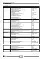
1.1 POSIZIONE DEI NUMERI DI SERIE...Pag. 1-4
1.1.1 NUMERO DI TELAIO ............................Pag. 1-4
1.1.2 NUMERO DI MOTORE .........................Pag. 1-4
1.2 AVVERTENZE PER IL CARBURANTE,
I LUBRIFICANTI E IL LIQUIDO
DI RAFFREDDAMENTO ........................Pag. 1-4
1.2.1 CARBURANTE .....................................Pag. 1-4
1.2.2 OLIO MOTORE .....................................Pag. 1-4
1.2.3 OLIO TRASMISSIONE..........................Pag. 1-6
1.2.4 OLIO FORCELLA .................................Pag. 1-6
1.2.5 LIQUIDO FRENI ....................................Pag. 1-6
1.2.6 LIQUIDO REFRIGERANTE ..................Pag. 1-8
1.3 NORME PER IL RODAGGIO .................Pag. 1-8
4
1.4 PRECAUZIONI E INFORMAZIONI
GENERALI ..............................................Pag. 1-12
1.5 PARTI DI RICAMBIO............................Pag. 1-14
5
1.6 CARATTERISTICHE TECNICHE.......Pag. 1-14
1.7 TABELLA LUBRIFICANTI ..................Pag. 1-16
6
7
8
1 -2
INFORMACIONES GENERALES
INFORMACIONES GENERALES
GENERAL INFORMATION
1
INDICE
GENERAL INFORMATION
1
TABLE OF CONTENTS
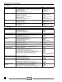
1.1 POSICION DE LOS NUMEROS
DE SERIE .................................................. Pag. 1-5
1.1.1 NUMERO BASTIDOR........................... Pag. 1-5
1.1.2 NUMERO MOTOR ................................ Pag. 1-5
1.1 POSITION
OF THE SERIAL NUMBERS ................ Pag. 1-5
1.1.1 FRAME NUMBER ................................. Pag. 1-5
1.1.2 ENGINE NUMBER ................................ Pag. 1-5
1.2 ADVERTENCIAS POR LO QUE SE REFIERE
AL COMBUSTIBLE, A LOS LUBRICANTES Y
AL LIQUIDO REFRIGERANTE ............ Pag. 1-5
1.2.1 COMBUSTIBLE .................................... Pag. 1-5
1.2.2 ACEITE MOTOR ................................... Pag. 1-5
1.2.3 ACEITE TRANSMISION ....................... Pag. 1-7
1.2.4 ACEITE HORQUILLA ........................... Pag. 1-7
1.2.5 LIQUIDO FRENOS ............................... Pag. 1-7
1.2.6 LIQUIDO REFRIGERANTE .................. Pag. 1-9
1.2 ADVICE FOR THE USE OF FUEL,
LUBRICANTS AND COOLANT ........... Pag. 1-5
1.2.1 FUEL ..................................................... Pag. 1-5
1.2.2 ENGINE OIL.......................................... Pag. 1-5
1.2.3 TRANSMISSION OIL ............................ Pag. 1-7
1.2.4 FORK OIL ............................................. Pag. 1-7
1.2.5 BRAKE FLUID ...................................... Pag. 1-7
1.2.6 COOLANT............................................. Pag. 1-9
1.3 NORMAS PARA EL RODAJE ............. Pag. 1-11
1.4 PRECAUCIONES
INFORMACIONES
E
GENERALES
Pag. 1-13
1.5 PIEZAS DE REPUESTO ...................... Pag. 1-14
1.6 FICHA TECNICA ................................... Pag. 1-14
1
2
3
1.3 RUNNING-IN.......................................... Pag. 1-11
1.4 PRECAUTIONSANDGENERALINFORMATION
Pag. 1-13
4
1.5 SPARE PARTS ...................................... Pag. 1-14
1.6 TECHNICAL SPECIFICATIONS ........ Pag. 1-14
1.7 LUBRICANT CHART............................ Pag. 1-17
1.7 TABLA LUBRICANTES ....................... Pag. 1-17
5
6
7
8
1 -3
INFORMAZIONI GENERALI
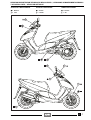
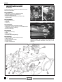
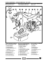
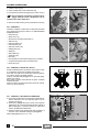
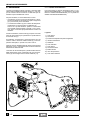
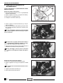
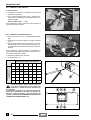
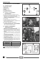
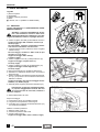
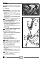
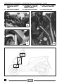
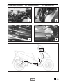
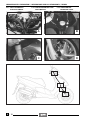
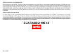
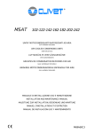
1.1 POSIZIONE DEI NUMERI DI SERIE
Questi numeri sono necessari per l’immatricolazione del
veicolo.
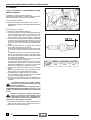
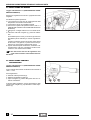
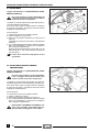
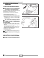
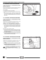
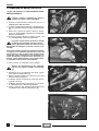
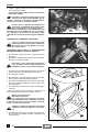
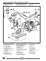
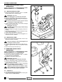
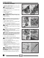
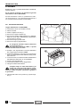
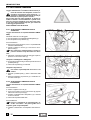
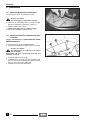
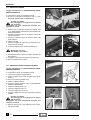
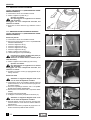
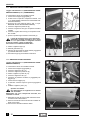
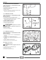
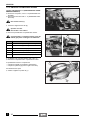
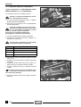
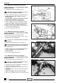
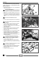
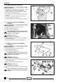
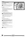
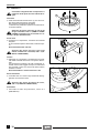
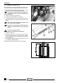
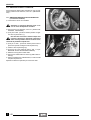
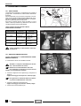
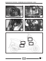
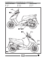
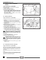
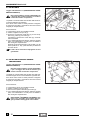
1.1.1 NUMERO DI TELAIO
Il numero telaio è stampigliato sul tubo centrale del telaio.
Per la lettura è necessario togliere il coperchietto (1).
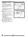
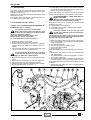
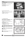
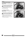
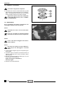
1.1.2 NUMERO DI MOTORE
Il numero del motore è stampigliato sul lato posteriore, vicino al tappo di riempimento olio trasmissione.
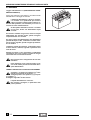
1.2 AVVERTENZE PER IL CARBURANTE,
I LUBRIFICANTI E IL LIQUIDO
DI RAFFREDDAMENTO
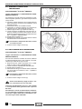
1.2.1 CARBURANTE
a
Il carburante utilizzato per la propulsione dei
motori a scoppio è estremamente infiammabile e può divenire esplosivo in determinate
condizioni. I vapori di carburante sono nocivi alla salute. Assicurarsi, prima di procedere, che il locale in
cui si opera abbia un adeguato ricambio d’aria.
È opportuno effettuare il rifornimento e le operazioni
di manutenzione in una zona ventilata, e a motore
spento. Non fumare durante il rifornimento di benzina e in vicinanza di vapori di carburante, in ogni caso
evitare assolutamente il contatto con fiamme libere,
scintille e qualsiasi altra fonte che potrebbe causarne
l’accensione o l’esplosione. Evitare inoltre la fuoriuscita di carburante dal bocchettone, in quanto potrebbe incendiarsi al contatto con le superfici roventi
del motore. Nel caso in cui involontariamente venisse versata della benzina, controllare che la zona sia
completamente asciutta; prima della messa in moto
del veicolo accertarsi che non sia rimasto del carburante sul collo del bocchettone.
La benzina si dilata al calore e sotto l’azione dell’irraggiamento solare. Perciò non riempire mai il serbatoio sino all’orlo. Chiudere accuratamente il tappo al
termine dell’operazione di rifornimento. Evitare il
contatto del carburante con la pelle, l’inalazione dei
vapori, l’ingestione e il travaso da un contenitore
all’altro con l’uso di un tubo.
Non disperdere il carburante nell’ambiente.
TENERE LONTANO DALLA PORTATA DEI BAMBINI
Utilizzare esclusivamente benzina super con o senza
piombo, con numero di ottano minimo 95 (N.O.R.M.) e 85
(N.O.M.M.) (4 Stars U).
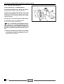
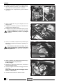
1.2.2 OLIO MOTORE
Controllare ogni 1000 chilometri il livello dell’olio motore,
vedi 2.9 (VERIFICA LIVELLO OLIO MOTORE E RABBOCCO).
È necessario sostituire l’olio del motore dopo i primi 1000
chilometri e successivamente ogni 6000 km, vedi 2.10
(SOSTITUZIONE OLIO MOTORE E FILTRO OLIO MOTORE).
1 -4
INFORMACIONES GENERALES
GENERAL INFORMATION
1.1 POSICION DE LOS NUMEROS DE SERIE
1.1 POSITION OF THE SERIAL NUMBERS
Estos números son necesarios para matricular el vehículo.
These numbers are necessary for the registration of the
vehicle.
1.1.1 NUMERO BASTIDOR
1.1.1 FRAME NUMBER
El numero del bastidor está impreso en el tubo central del
bastidor. Para leerlo es necesario quitar la tapa (1).
The frame number is stamped on the central tube of the
frame. To be able to read it, it is necessary to remove the
cover (1).
1.1.2 NUMERO MOTOR
1.1.2 ENGINE NUMBER
El numero del motor está impreso en lado trasero, cerca
del tapón de llenado aceite transmisión.
The engine number is stamped on the rear part of the vehicle, near the transmission oil filling plug.
1.2 ADVERTENCIAS POR LO QUE SE REFIERE
AL COMBUSTIBLE, A LOS LUBRICANTES
Y AL LIQUIDO REFRIGERANTE
1.2 ADVICE FOR THE USE OF FUEL,
LUBRICANTS AND COOLANT
1.2.1 COMBUSTIBLE
1.2.1 FUEL
El combustible utilizado para la propulsión de
los motores de explosión es muy inflamable y
puede volverse explosivo en algunas condiciones. Los vapores de combustible perjudican la salud. Antes de seguir adelante, asegúrese de que el lugar donde va a actuar tenga un adecuado cambio de
aire. Es oportuno reponer gasolina y realizar las operaciones de mantenimiento en una zona ventilada, y
con el motor apagado. No fume durante la provisión
de gasolina y cerca de los vapores del combustible;
de todas formas evite absolutamente el contacto con
llamas libres, chispas y cualquier otra fuente que podría causar el encendido o la explosión. Además, evite la salida del combustible de la boca de llenado, ya
que podría incendiarse al llegar a contacto con las
superficies muy calientes del motor. En caso de que
se vertiera accidentalmente algo de gasolina, controle que la zona esté completamente seca; antes de
arrancar asegúrese de que no haya quedado nada de
combustible en el manguito de la boca de llenado.
La gasolina se dilata con el calor y bajo la acción de
los rayos solares. Por lo tanto no llene nunca el depósito hasta el tope. Una vez que se haya terminado
la operación de provisión de gasolina, cierre con cuidado el tapón. Evite el contacto del combustible con
la piel, la inhalación de vapores, la ingestión y el trasiego de un recipiente a otro por medio de un tubo.
a
The fuel used for internal combustion engines
is extremely inflammable and in particular
conditions it can become explosive.
Fuel vapours are noxious for the health.
It is important to carry out the refuelling and the
maintenance operations in a well-ventilated area,
with the engine off.
Do not smoke while refuelling or near fuel vapours, in
any case avoid any contact with naked flames,
sparks and any other heat source to prevent the fuel
from catching fire or from exploding.
Further, prevent fuel from flowing out of the fuel filler,
as it could catch fire when getting in contact with the
red-hot surfaces of the engine.
In case some fuel has accidentally been spilt, make
sure that the area has completely dried and before
starting the vehicle verify that there is no fuel inside
the fuel filler neck.
Since petrol expands under the heat of the sun and
due to the effects of sun radiation, never fill the tank
to the brim.
Screw the plug up carefully after refuelling.
Avoid any contact of the fuel with the skin and the inhalation of vapours; do not swallow fuel or pour it
from a receptacle into another by means of a tube.
No esparza el combustible en el ambiente.
Do not dispose of fuel in the environment.
MANTENGASE LEJOS DEL ALCANCE DE LOS NIÑOS
KEEP AWAY FROM CHILDREN
Utilice exclusivamente gasolina super con o sin plomo, mínimo octano 95 (N.O.R.M.) y 85 (N.O.M.M.) (4 Stars U).
Use only leaded or unleaded premium grade petrol (4
Stars U), min. O.N. 95 (N.O.R.M.) and 85 (N.O.M.M.).
1.2.2 ACEITE MOTOR
1.2.2 ENGINE OIL
Controle cada 1000 kilómetros el nivel del aceite motor,
véase 2.9 (COMPROBACION NIVEL ACEITE MOTOR
Y RELLENO). Hay que sustituir el aceite del motor tras
los primeros 1000 kilómetros y sucesivamente cada
6000 km, véase 2.10 (SUSTITUCION ACEITE MOTOR
Y FILTRO ACEITE MOTOR).
Check the engine oil level every 1000 km, see 2.9 (CHECKING THE ENGINE OIL LEVEL AND TOPPING UP).
It is necessary to change the engine oil after the first
1000 km and successively every 6000 km, see 2.10
(CHANGING THE ENGINE OIL AND THE OIL FILTER).
a
1 -5
INFORMAZIONI GENERALI
a
Utilizzare olî di buona qualità di gradazione
5W-40, vedi 1.7 (TABELLA LUBRIFICANTI).
L’utilizzo di olî di gradazione SAE 15W o 20W
potrebbe comportare difficoltà in fase di avviamento
veicolo, se la temperatura ambiente è inferiore a
+5˚C.
a
a
In caso di rabbocco olio motore si raccomanda di non superare il livello “MAX”.
L’olio motore può causare seri danni alla pelle se maneggiato a lungo e quotidianamente.
Si consiglia di lavare accuratamente le mani
dopo averlo maneggiato.
NON DISPERDERE L’OLIO NELL’AMBIENTE.
Consegnarlo o farlo ritirare dalla più vicina azienda di
recupero olî usati o dal fornitore.
1.2.3 OLIO TRASMISSIONE
a
L’olio trasmissione può causare seri danni
alla pelle se maneggiato a lungo e quotidianamente. Si consiglia di lavare accuratamente le mani dopo averlo maneggiato.
Controllare il livello olio trasmissione ogni 6000 km o ogni
8 mesi.
Sostituire l’olio trasmissione dopo i primi 1000 km e successivamente ogni 12000 km o ogni 16 mesi.
Olio trasmissione (consigliato): vedi 1.7 (TABELLA
LUBRIFICANTI)
1.2.4 OLIO FORCELLA
a
L’olio forcella può causare seri danni alla
pelle se maneggiato a lungo e quotidianamente. Si consiglia di lavare accuratamente
le mani dopo averlo maneggiato.
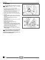
Se si riscontrano, o vengono lamentati, dei “fondo corsa”
forcella è necessario controllare il livello olio degli steli.
Olio forcella (consigliato): vedi 1.7 (TABELLA LUBRIFICANTI)
1.2.5 LIQUIDO FRENI
c
Questo veicolo è dotato di freni a disco anteriore e posteriore, con circuiti idraulici separa-
ti.
Le seguenti informazioni sono riferite a un singolo impianto frenante, ma sono valide per entrambi.
a
Non utilizzare liquidi diversi da quelli prescritti
e non miscelare liquidi differenti per il rabbocco, per non danneggiare l'impianto frenante.
Non impiegare liquido freni prelevato da contenitori
vecchi o già aperti. Non usare liquido freni avanzato
da precedenti riparazioni se è trascorso molto tempo.
1 -6
INFORMACIONES GENERALES
GENERAL INFORMATION
a
Use high-quality 5W-40 oil, see 1.7 (LUBRICANT CHART).
The use of oils with SAE number 15W or 20W
may create problems when starting the vehicle, if
room temperature is lower than +5˚C.
Utilice aceites con buena calidad de gradación 5W-40, véase 1.7 (TABLA LUBRICANTES). El uso de aceites de gradación SAE 15W
o 20W podría plantear algún problema durante la fase
de arranque del vehículo, si la temperatura ambiente
es inferior a +5˚C.
a
a
En caso de relleno del aceite del motor, le recomendamos que no supere el nivel “MAX”.
El aceite del motor puede dañar a la piel si manejado durante mucho tiempo y diariamente.
Se aconseja lávese las manos con mucho cuidado tras haberlo manejado.
NO ESPARZA EL ACEITE EN EL AMBIENTE.
Pida que pasen a recogerlo o entréguelo a la empresa de recuperación aceites usados más cercana o al
abastecedor.
a
a
a
When topping up the engine oil, never exceed
the “MAX” level.
Engine oil can cause serious damages to the
skin if handled every day and for long periods.
Wash your hands carefully after using the oil.
DO NOT DISPOSE OF THE ENGINE OIL IN THE ENVIRONMENT.
Take it to the nearest company specialized in the disposal of used oils or to the filling station where you
usually buy it.
1.2.3 ACEITE TRANSMISION
1.2.3 TRANSMISSION OIL
El aceite transmisión puede dañar gravemente a la piel si manejado durante mucho tiempo
y diariamente. Se aconseja lávese las manos
con mucho cuidado tras haberlo manejado.
a
Transmission oil can cause serious damages
to the skin if handled every day and for long
periods. Wash your hands carefully after using the oil.
Controle el nivel aceite transmisión cada 6000 km o cada
8 meses.
Sustituya el aceite transmisión tras los primeros 1000 km
y sucesivamente cada 12000 km o cada 16 meses.
Check the transmission oil level every 6000 km or every 8
months.
Change the transmission oil after the first 1000 km and
successively every 12000 km or every 16 months.
Aceite transmisión (aconsejado): véase 1.7 (TABLA
LUBRICANTES)
Transmission oil (recommended): see 1.7 (LUBRICANT CHART)
1.2.4 ACEITE HORQUILLA
1.2.4 FORK OIL
a
a
El aceite transmisión puede dañar gravemente a la piel si manejado durante mucho tiempo
y diariamente. Se aconseja lávese las manos
con mucho cuidado tras haberlo manejado.
En caso de que note o en caso de que alguien se queje
de que la horquilla se hunda excesivamente, controle el
nivel aceite de las varillas.
a
Fork oil can cause serious damages to the
skin if handled every day and for long periods.
Wash your hands carefully after using the oil.
If the fork rods sink excessively, it is advisable to check
the rod oil level.
Fork oil (recommended): see 1.7 (LUBRICANT
CHART)
Aceite horquilla (aconsejado): véase 1.7 (TABLA LUBRICANTES)
1.2.5 LIQUIDO FRENOS
1.2.5 BRAKE FLUID
Este vehículo está dotado de frenos de disco
delantero y trasero, con circuitos hidráulicos
separados.
Las siguientes informaciones se refieren a un solo
sistema de frenado, pero tienen validez incluso para
ambos sistemas.
This vehicle is provided with front and rear
disc brakes, with separate hydraulic circuits.
The following information refers to a single braking
system, but is valid for both.
c
a
No utilice líquidos distintos de los prescritos
ni mezcle líquidos diferentes para rellenar,
porque en caso contrario se puede dañar el
sistema de frenado.
No use líquido frenos sacado de recipientes viejos o
ya abiertos. No utilice líquido frenos que haya sobrado de reparaciones anteriores si ya ha transcurrido
mucho tiempo.
c
a
Do not use fluids different from the recommended ones and do not mix different fluids
for topping up, to avoid serious damages to
the braking system.
Do not use brake fluid taken from old or already open
containers. Do not use brake fluid left from previous
repairs if these were carried out long ago.
1 -7
INFORMAZIONI GENERALI
a
Prestare particolare attenzione che il disco del
freno non sia unto o ingrassato, specialmente dopo l’esecuzione di operazioni di manutenzione o controllo. Improvvise variazioni del gioco
o una resistenza elastica sulle leve dei freni, sono dovute a inconvenienti all’impianto idraulico.
Controllare che il tubo del freno non risulti attorcigliato o consumato.
Fare attenzione che acqua o polvere non entrino
inavvertitamente all'interno del circuito.
ll liquido freni potrebbe causare irritazioni se venisse
a contatto con la pelle o con gli occhi.
Lavare accuratamente le parti del corpo che venissero a contatto con il liquido, inoltre rivolgersi a un oculista o a un medico se il liquido venisse a contatto
con gli occhi.
Non disperdere il liquido nell'ambiente.
TENERE LONTANO DALLA PORTATA DEI BAMBINI.
a
Usando il liquido dei freni, fare attenzione a
non rovesciarlo sulle parti in plastica e/o verniciate, perchè queste si danneggiano.
Liquido freni (consigliato): vedi 1.7 (TABELLA LUBRIFICANTI)
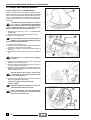
1.2.6 LIQUIDO REFRIGERANTE
a
Non utilizzare il veicolo se il livello del liquido
refrigerante è al di sotto del livello minimo.
Controllare ogni 2000 km e dopo lunghi viaggi il livello del
liquido refrigerante; sostituirlo ogni 16 mesi.
La soluzione di liquido refrigerante è composta da 50% di
acqua e 50% di antigelo. Questa miscela è ideale per la
maggior parte di temperature di funzionamento e garantisce una buona protezione contro la corrosione.
È conveniente mantenere la stessa miscela anche nella
stagione calda perché si riducono così le perdite per evaporazione e la necessità di frequenti rabbocchi. In questo
modo diminuiscono i depositi di sali minerali, lasciati nel
radiatore dall’acqua evaporata e si mantiene inalterata
l’efficienza del sistema di raffreddamento.
Nel caso in cui la temperatura esterna sia al di sotto dei
zero gradi centigradi, controllare frequentemente il circuito
refrigerante aggiungendo, se necessario, una concentrazione maggiore di antigelo (fino a un massimo del 60%).
Per la soluzione refrigerante utilizzare acqua distillata,
per non rovinare il motore.
a
Non togliere il tappo del vaso di espansione a
motore caldo, perché il refrigerante è sotto
pressione e a temperatura elevata.
Al contatto con la pelle o i vestiti può causare serie
ustioni e/o danni.
Lavare accuratamente le parti del corpo che venissero a contatto con il liquido refrigerante, inoltre rivolgersi a un oculista o a un medico se il liquido venisse
a contatto con gli occhi.
Il liquido refrigerante è nocivo: NON INGERIRE.
TENERE LONTANO DALLA PORTATA DEI BAMBINI
Provocare il vomito e consultare un medico se il liquido refrigerante viene ingerito.
Liquido refrigerante del motore (consigliato): vedi 1.7
(TABELLA LUBRIFICANTI)
a
Impiegare solo antigelo e anticorrosivo senza
nitrito, che assicuri una protezione almeno ai
-35˚C.
1 -8
INFORMACIONES GENERALES
GENERAL INFORMATION
Ponga cuidado, sobre todo, en que el disco
del freno no esté untado o engrasado, sobre
todo tras las operaciones de mantenimiento o
de control. Variaciones improvisas del juego o una
resistencia elástica sobre las palancas de los frenos,
se deben a defectos en el sistema hidráulico. Controle que el tubo del freno no resulte enroscado o desgastado. Tenga cuidado con que agua o polvo no entren accidentalmente en el interior del circuito.
El líquido de los frenos podría causar irritaciones si
llega a contacto con la piel o con los ojos. Lávese
con mucho cuidado las partes del cuerpo que hayan
estado en contacto con el líquido, y, además, diríjase
a un oculista o a un médico si el líquido llegara a contacto con los ojos.
No esparza el líquido en el ambiente.
a
Make sure that the brake disc is neither oily,
nor greasy, especially after maintenance or
checking operations. Sudden resistance or
clearance problems on the brake lever may be due to
troubles in the hydraulic system.
Check that the brake cable is neither twisted, nor
worn out.
Prevent water or dust from accidentally getting into
the circuit.
If the brake fluid gets in contact with the skin or the
eyes, it can cause serious irritations.
Carefully wash the parts of your body that get in contact with the fluid. Consult a doctor or an oculist if the
fluid gets in contact with your eyes.
Do not dispose of the brake fluid in the environment.
MANTENGASE LEJOS DEL ALCANCE DE LOS NIÑOS.
KEEP AWAY FROM CHILDREN.
a
a
Utilizando el líquido de los frenos, tenga cuidado con no verterlo sobre las partes de plástico
y/o barnizadas, porque podría estropearlas.
a
When using the brake fluid, take care not to
spill it on the plastic and/or painted parts,
since it can damage them.
Líquido frenos (aconsejado): véase 1.7 (TABLA LUBRICANTES)
Brake fluid (recommended): see 1.7 (LUBRICANT
CHART)
1.2.6 LIQUIDO REFRIGERANTE
1.2.6 COOLANT
a
a
No utilice el vehículo si el nivel del líquido refrigerante está por debajo del nivel mínimo.
Controle cada 2000 km y tras largos viajes el nivel del líquido refrigerante; sustitúyalo cada 16 meses.
La solución del líquido refrigerante está compuesta por
50% de agua y por 50% de anticongelante. Esta mezcla
es ideal para casi todas las temperaturas de funcionamiento y garantiza una buena protección contra la corrosión. Se aconseja mantenga la misma mezcla incluso durante la temporada caliente porque, de tal forma, se
reducen las pérdidas por evaporación y la necesidad de
frecuentes rellenos. De tal manera disminuyen las incrustaciones de sales minerales, dejadas en el radiador por el
agua evaporada y se conserva inalterada la eficiencia del
sistema de refrigeración. En caso de que la temperatura
exterior esté por debajo de cero grados centígrados, controle frecuentemente el circuito de refrigeración añadiendo, si necesario, una mayor concentración de anticongelante (hasta un máximo de 60%). Para la solución
refrigerante use agua destilada, para no dañar el motor.
a
No quite el tapón del depósito de expansión
con el motor aún caliente, porque el líquido
refrigerante está bajo presión y a temperatura
elevada. Si llega a contacto con la piel o con la ropa
puede causar graves quemaduras y/o daños. Lávese
con mucho cuidado las partes del cuerpo que hayan
estado en contacto con el líquido, y, además, diríjase
a un oculista o a un médico si el líquido llegara a contacto con los ojos.
El líquido refrigerante es nocivo: NO LO TRAGUE.
MANTENGASE LEJOS DEL ALCANCE DE LOS NIÑOS
Provoque el vómito y consulte al médico en caso de
que trague una parte del líquido refrigerante.
Do not use the vehicle if the coolant is below
the minimum prescribed level.
Check the coolant level every 2000 km and after long
rides; change it every 16 months.
The coolant is made up of 50% water and 50% antifreeze. This mixture is ideal for most running temperatures and ensures good protection against corrosion.
It is advisable to keep the same mixture also in the hot
season, since in this way losses due to evaporation are
reduced and it is not necessary to top up very frequently.
The mineral salt deposits left in the radiator by evaporated water are thus reduced and the efficiency of the cooling system remains unchanged.
If the outdoor temperature is below 0˚, check the cooling
circuit frequently and if necessary increase the antifreeze
concentration (up to maximum 60%).
For the cooling solution use distilled water, in order not to
damage the engine.
a
Do not remove the expansion tank cap when
the engine is hot, since the coolant is under
pressure and its temperature is high.
If it gets in contact with the skin or with clothes it may
cause severe burns and/or damages.
Carefully wash the parts of your body that get in contact with the coolant. Consult a doctor or an oculist if
the coolant gets in contact with your eyes.
The coolant is noxious: DO NOT SWALLOW IT.
KEEP AWAY FROM CHILDREN
If someone swallows the coolant, make him/her vomit and consult a doctor without delay.
Líquido refrigerante del motor (aconsejado): véase 1.7
(TABLA LUBRICANTES).
Engine coolant (recommended): see 1.7 (LUBRICANT
CHART).
a
a
Utilice sólo anticongelante y antioxidante sin
nitrito que garantice una protección por lo
menos a los -35˚C.
Use only antifreeze and anticorrosive without
nitrite, in order to ensure protection at -35˚C at
least.
1 -9
INFORMAZIONI GENERALI
1.3 NORME PER IL RODAGGIO
Il rodaggio del motore è fondamentale per garantirne la
successiva durata e il corretto funzionamento.
a
Soltanto dopo i primi 500 km di rodaggio è
possibile ottenere le migliori prestazioni di accelerazione e velocità del veicolo.
Attenersi alle seguenti indicazioni:
◆
◆
◆
Non ruotare completamente la manopola acceleratore
ai bassi regimi, sia durante che dopo il rodaggio.
Durante i primi 1000 km, non guidare il veicolo oltre
l’80% della velocità massima.
Evitare di mantenere, per lunghi tratti di strada, una
velocità costante.
a
Dopo i primi 1000 km di funzionamento, eseguire i controlli previsti nella colonna “fine rodaggio” della SCHEDA DI MANUTENZIONE
PERIODICA, vedi 2.1.1 (SCHEDA DI MANUTENZIONE
PERIODICA), al fine di evitare danni a sé stessi, agli
altri e/o al veicolo.
1 - 10
INFORMACIONES GENERALES
GENERAL INFORMATION
1.3 NORMAS PARA EL RODAJE
1.3 RUNNING-IN
El rodaje del motor es fundamental para garantizar una
duración larga y el correcto funcionamiento.
The running-in of the engine is primary to ensure its correct functioning.
a
a
Sólo tras los primeros 500 kilómetros de rodaje
es posible conseguir las mejores prestaciones
de aceleración y de velocidad del vehículo.
Siga las siguientes indicaciones:
◆
◆
◆
No gire del todo el puño de gas durante bajos régimenes, sea durante que después del rodaje.
Durante los primeros 1000 km, no conduzca por encima del 80% de la velocidad máxima.
Evite mantener, durante largos trechos, una velocidad
constante.
a
Después de los primeros 1000 km de funcionamiento, realice los controles señalados en
la columna “fin rodaje” de la FICHA DE MANTENIMIENTO PERIODICO, véase 2.1.1 (FICHA DE
MANTENIMIENTO PERIODICO), para evitar daños a
los demás, a sí mismo y/o al vehículo.
Only after the first 500 km of running-in it is
possible to obtain the best performance from
the vehicle speed and acceleration.
Keep to the following indications:
◆
◆
◆
Do not open the throttle completely if the speed is low,
both during and after the running-in.
During the first 1000 km, do not exceed the 80% of the
maximum allowed speed.
Avoid driving at constant speed for long distances.
a
After the first 1000 kilometres, carry out the
checking operations indicated in the column
“After running-in” of the REGULAR SERVICE
INTERVALS CHART, see 2.1.1 (REGULAR SERVICE
INTERVALS CHART), in order to avoid hurting yourself or other people and/or damaging the vehicle.
1 - 11
INFORMAZIONI GENERALI
1.4 PRECAUZIONI E INFORMAZIONI
GENERALI
Quando si esegue la riparazione, lo smontaggio e il rimontaggio dei componenti del veicolo, attenersi scrupolosamente alle seguenti raccomandazioni.
a
Per qualsiasi tipo di operazione è vietato l'uso
di viva fiamma.
Prima di iniziare qualsiasi intervento di manutenzione o ispezione al veicolo, fermare il motore e
togliere la chiave, attendere che motore e impianto di
scarico si siano raffreddati, sollevare possibilmente
il veicolo con apposita attrezzatura, su di un terreno
solido e in piano.
Porre particolare attenzione alle parti ancora calde
del motore e dell' impianto di scarico, in modo tale da
evitare ustioni.
Il veicolo è costruito con parti non commestibili.
Non mordere, succhiare, masticare o ingerire nessuna parte dello stesso per nessun motivo.
Se non espressamente descritto, il rimontaggio dei
gruppi segue in senso inverso le operazioni di smontaggio.
Non far funzionare il motore in luoghi chiusi o poco
aerati.
Maneggiare la benzina, che è estremamente infiammabile e fortemente esplosiva, con la massima cura.
Non utilizzare mai la benzina come solvente per la
pulizia del veicolo.
Quando due o più persone lavorano contemporaneamente, prestare attenzione alla sicurezza di ciascuno.
– Utilizzare esclusivamente RICAMBI ORIGINALI aprilia.
– Attenersi all'impiego dei lubrificanti consigliati.
– Impiegare, dove previsto, gli attrezzi speciali progettati
per questo veicolo.
– Nel serraggio di viti e dadi, iniziare con quelli di diametro maggiore oppure quelli interni, procedendo in diagonale con passaggi successivi.
– Pulire accuratamente i componenti smontati, con detergente a basso grado di infiammabilità.
– Lubrificare le parti (ovviamente quando è possibile) prima di rimontarle.
– Controllare che ogni componente sia stato montato in
modo corretto.
– Sostituire sempre le guarnizioni, gli anelli di tenuta, gli
anelli elastici, gli anelli O-Ring (OR) e le copiglie con altri nuovi.
– Contrassegnare le posizioni su tutti i giunti di connessioni (tubi, cavi, ecc.) prima di dividerli e identificarli
con segni distintivi differenti.
Ogni pezzo va segnato chiaramente per poter essere
identificato in fase di installazione.
a
Non riutilizzare mai un anello elastico.
Quando viene smontato da un albero deve essere sostituito con uno nuovo.
Quando si monta un anello elastico nuovo, fare attenzione a non allontanare le sue estremità più dello
stretto necessario per infilarlo all’albero.
Dopo il montaggio di un anello elastico, verificare
che sia completamente e saldamente inserito nella
sua sede.
1 - 12
INFORMACIONES GENERALES
GENERAL INFORMATION
1.4 PRECAUCIONES E INFORMACIONES
GENERALES
1.4 PRECAUTIONS AND GENERAL
INFORMATION
Cuando realiza las operaciones de reparación, de desmontaje y de instalación del vehículo, siga esmeradamente las siguientes recomendaciones.
Keep to the following instructions when repairing, disassembling and reassembling the vehicle.
a
Para cualquier tipo de operación está prohibido el uso de llama viva.
Antes de empezar cualquier tipo de intervención de mantenimiento o de inspección al vehículo,
pare el motor, y quite la llave, espere a que el motor y
el sistema de escape se hayan enfriado, levante el vehículo posiblemente por medio del equipo adecuado,
sobre una superficie sólida y llana.
Ponga cuidado sobre todo en las partes aún muy calientes del motor y del sistema de escape, para evitar
quemaduras. El vehículo está construido con partes
no comestibles. No muerda, no chupe, no mastique ni
trague ninguna parte del mismo por ninguna razón.
De no resultar expresamente descrito, hay que instalar los grupos siguiendo en orden contrario las operaciones que se han efectuado para el desmontaje.
No haga funcionar el motor en lugares cerrados o
con poco aire.
Maneje con mucho cuidado la gasolina porque es extremadamente inflamable y muy explosiva.
a
The use of naked flames is forbidden for any
kind of operation.
Before performing any maintenance operation
or any inspection of the vehicle, stop the engine, extract the key, wait until the engine and the exhaust
system have cooled down and if possible lift up the
vehicle by means of the proper equipment, on firm
and flat ground.
Keep away from the red-hot parts of the engine and
of the exhaust system, in order to avoid burns.
The vehicle is made up of not edible parts.
Never bite, suck, chew or swallow any part of the vehicle for any reason.
If not expressly indicated otherwise, for the reassembly of the units repeat the disassembly operations in
the reverse order.
Do not let the engine run in close or badly ventilated
places.
Petrol is highly inflammable and explosive, therefore
always handle it with care.
Never use petrol as a solvent to clean the vehicle.
No utilice nunca la gasolina como disolvente para
limpiar el vehículo.
Cuando dos o más personas trabajan contemporáneamente, ponga cuidado en la seguridad de cada
uno de ellas.
– Utilice exclusivamente REPUESTOS ORIGINALES
aprilia.
– Utilice los lubricantes aconsejados.
– Use, donde previsto, las herramientas especiales proyectadas para este vehículo.
– Al apretar los tornillos y las tuercas, empiece por los
que tienen el diámetro mayor o por los que están en el
interior, siguiendo en diagonal con pasajes sucesivos.
– Limpie con mucho cuidado los componentes desmontados, con detergente a bajo nivel de inflamabilidad.
– Lubrique las partes (claramente cuando es posible)
antes de instalarlas.
– Controle que cada componente haya sido instalado de
manera correcta.
– Sustituya siempre las juntas, los aros tóricos, los anillos elásticos, las empaquetaduras de anillo (OR) y las
clavijas con otros nuevos.
– Marque la posición sobre todos los empalmes de conexión (tubos, cables, etc.) antes de dividirlos e identifíquelos con signos distintos.
Hay que marcar claramente cada pieza para poder
identificarla en fase de instalación.
a
No vuelva a utilizar nunca un anillo elástico.
Hay que sustituirlo con otro nuevo cuando se
desmonta de un eje.
Cuando se instala un anillo elástico nuevo, ponga
cuidado en no alejar sus extremidades más de lo necesario para introducirlo en el eje.
Tras haber instalado un anillo elástico, compruebe
que esté introducido del todo y fijamente en su sede.
When two or more people are working together, make
sure that everyone is working in safe conditions.
– Use aprilia GENUINE SPARE PARTS only.
– Use the recommended lubricants.
– When provided, use the special tools designed for this
vehicle.
– In the tightening of screws and nuts, start with those
having greater diameter or with the inner ones, proceeding diagonally with successive passages.
– Carefully clean the disassembled components, with
low inflammability detergents.
– When possible, lubricate the parts before reassembly.
– Make sure that each component has been properly
reassembled.
– Always replace gaskets, seals, grommets, circlips, Orings and split pins with new ones.
– Before disconnecting the joints (pipes, cables, etc.),
mark the positions on all of them and mark them with
different distinguishing signs.
Each piece must be marked clearly, in order not to
have problems during installation.
a
Never use an circlip twice.
When it is removed from a shaft, it must be replaced with a new one.
When installing a new circlip, be careful not to separate its ends more than necessary to insert it on the
shaft.
After installing an circlip, make sure that it is completely and firmly inserted in its seat.
1 - 13
INFORMAZIONI GENERALI / INFORMACIONES GENERALES / GENERAL INFORMATION
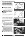
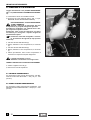
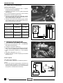
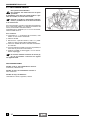
1.5 PARTI DI RICAMBIO
1.5 PIEZAS DE REPUESTO
1.5 SPARE PARTS
In caso di sostituzione, utiizzare solo
Ricambi Originali aprilia. I Ricambi
Originali aprilia sono di alta qualità,
progettati e costruiti espressamente
per i veicoli aprilia.
En caso de sustitución, utilice sólo
Repuestos Originales aprilia. Los
Repuestos Originales aprilia son de
calidad superior, proyectados y
construidos expresamente para vehículos aprilia.
For any replacement, use aprilia
Genuine Spare Parts only. aprilia
Genuine Spare Parts are high-quality
parts, expressly designed and manufactured for aprilia vehicles.
a
L’impiego di ricambi NON
originali aprilia può causare problemi di prestazioni e danneggiamenti.
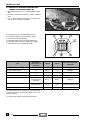
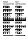
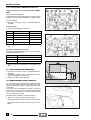
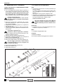
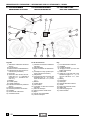
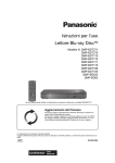
1.6 CARATTERISTICHE
TECNICHE
a
Lo de utilizar repuestos NO
originales aprilia puede
causar daños y graves problemas en las prestaciones.
1.6 FICHA TECNICA
a
Failure to use aprilia Genuine Spare Parts may result
in incorrect performance
and damages.
1.6 TECHNICAL
SPECIFICATIONS
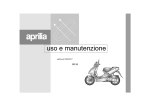
DIMENSIONI / DIMENSIONS / DIMENSIONS
1940 mm
Lunghezza max / Longitud máx. / Max. length
720 mm
Larghezza max / Anchura máx. / Max. width (rear-view mirrors included)
Altezza max (al cupolino) / Altura máx. (hasta el elemento frontal) / Max. height (front 1200 mm
part of the fairing included)
800 mm
Altezza alla sella / Altura hasta el sillín / Seat height
1320 mm
Interasse / Distancia entre los ejes / Distance between centres
155 mm
Altezza libera minima dal suolo / Altura libre mínima del suelo / Min. ground clearance
136 kg
Peso a vuoto (in ordine di marcia) / Peso en vacío (en orden de marcha) /
Weight without driver (ready for starting)
MOTORE / MOTOR / ENGINE
Tipo / Tipo / Type
Numero cilindri / Número cilindros / Number of cylinders
Cilindrata / Cilindrada total / Total displacement
Alesaggio e corsa / Diámetro y carrera / Bore and stroke
Rapporto di compressione / Relación de compresión / Compression ratio
Avviamento / Arranque / Starting
Frizione / Embrague / Clutch
Cambio / Cambio / Change gear
Raffreddamento / Refrigeración / Cooling
CAPACITÀ / CAPACIDAD / CAPACITY
Carburante (inclusa riserva) / Combustible (reserva incluida) / Fuel (reserve
included)
Riserva carburante / Reserva combustible / Fuel reserve
Olio motore / Aceite motor / Engine oil
ROTAX 120 - monocilindrico 4 tempi con 4 valvole, lubrificazione forzata a carter umido, albero a camme in testa. /
ROTAX 120-monocilíndrico de 4 tiempos con 4 válvulas,
lubricación forzada con cárter húmedo, árbol de levas en la
culata / ROTAX 120 - one-cylinder, 4-stroke with 4 valves,
forced lubrication with wet crankcase, camshaft at the
head
1
124,91 cm∏
56,4 mm / 50 mm
12,5 ± 0,5 : 1
elettrico / eléctrico / electric
centrifuga / centrífuga / centrifugal
automatico / automático / automatic
a liquido (50% acqua + 50% di liquido refrigerante) / por
líquido (50% agua + 50% líquido refrigerante) /
liquid-cooled (50% water + 50% coolant)
9,5 l
2,5 l
1050 cmC cambio olio, 1100 cmC cambio olio e filtro,
1150 cmC revisione del motore / 1050 cmC cambio aceite,
1100 cmC cambio aceite y filtro, 1150 cmC revisión del
motor / 1050 cmC oil change, 1100 cmC oil and filter
change, 1150 cmC engine overhaul
90 cmC
Olio trasmissione / Aceite transmisión / Transmission oil
Impianto di raffreddamento / Instalacion de refrigeracion / Cooling system
1200 cmC
2
Posti / Asientos / Seats
Max carico veicolo (pilota + passeggero + bagaglio) / Máx. carga vehículo (piloto + pasa- 180 kg
jero + equipaje) / Vehicle max. load (driver + passenger + luggage)
1 - 14
INFORMAZIONI GENERALI / INFORMACIONES GENERALES / GENERAL INFORMATION
TRASMISSIONE / TRANSMISION / TRANSMISSION
Variatore / Variador / Speed change gear
Primaria / Primaria / Primary
Secondaria / Secundaria / Secondary
Rapporto totale motore/ruota / Relación total motor/rueda-mínimo / Total engine/
wheel ratio
CARBURATORE / CARBURADOR / CARBURETTOR
Modello / Modelo / Model
Diffusore (ovale) / Difusor (oval) / Choke tube (oval)
ALIMENTAZIONE / ALIMENTACION / FUEL SUPPLY
Tipo / Tipo / Type
Carburante /
Combustible /
continuo automatico / continuo automático / automatic
stepless
a cinghia trapezoidale / por correa trapecial / V-belt
a ingranaggi / por engranajes / with gears
minimo 26,88 - massimo 8,06 / 26,88 - máximo: 8,06 / minimum 26,88 - maximum 8,06
Mikuni BS 26-49 (Mikuni BS 26-61 C)
diametro equivalente 22 mm / Diámetro equivalente 22 mm /
equivalent Ø22 mm
pompa a depressione / Bomba de depresión / vacuum pump
benzina con o senza piombo, con numero di ottano minimo 95
(N.O.R.M.) e 85 (N.O.M.M.) (4 Stars U) /
gasolina con o sin plomo, mínimo octano 95 (N.O.R.M.) y 85
(N.O.M.M.) (4 Stars U) /
leaded or unleaded premium grade petrol, min. O.N. 95
(N.O.R.M.) and 85 (N.O.M.M.) (4 Stars U)
TELAIO / BASTIDOR / FRAME
Tipo / Tipo / Type
Angolo inclinazione sterzo / Ángulo inclinación dirección / Steering inclination angle
Avancorsa / Lanzamiento / Fore stroke
SOSPENSIONI / SUSPENSIONES / SUSPENSIONS
Anteriore / Delantera / Front
Escursione / Carrera / Stroke
Posteriore / Trasera / Rear
Escursione / Carrera / Stroke
FRENI / FRENOS / BRAKES
Anteriore / Delantero / Front
Posteriore / Trasero / Rear
monotrave a doppia culla sovrapposta / monoviga de doble
cuna sobrepuesta / one-beam, split in two overlapping cradles
25˚
88 mm
forcella telescopica a funzionamento idraulico / horquilla telescópica con funcionamiento hidráulico / hydraulically operated
telescopic fork
90 mm
n˚2 ammortizzatori idraulici / n˚ 2 amortiguadores hidráulicos /
n.2 hydraulic shock absorbers
104 mm
a disco Ø 220 mm con trasmissione idraulica / de disco Ø 220
mm - con transmisión hidráulica / disc brake, 220 mm with
hydraulic transmission
a disco Ø 190 mm con trasmissione idraulica / de disco
Ø190 mm - con transmisión hidráulica / disc brake, Ø190 mm,
with hydraulic transmission
RUOTE / RUEDAS / WHEELS
CERCHI / LLANTAS / RIMS
Anteriore / Delantera / Front
E - 12 x 3.00 DOT - D
Posteriore / Trasera / Rear
E - 12 x 3.50 DOT - D
PNEUMATICI / NEUMATICOS / TYRES
Anteriore / Delantera / Front
130 / 70 - 12” 56 L
In alternativa / En sustitución / Alternatively
130 / 70 - 12” 56 P; 120 / 70 - 12” 51 P; 130 / 70 - 12” 56 J
Posteriore / Trasero / Rear
140 / 70 - 12” 60 P
In alternativa / En sustitución / Alternatively
140 / 70 - 12” 60 L; 140 / 70 - 12” 60 J
PRESSIONE DI GONFIAGGIO STANDARD / PRESION DE HINCHADO ESTANDARD / STANDARD INFLATION PRESSURE
Anteriore / Delantera / Front
190 kPa (1,9 bar)
Posteriore / Trasero / Rear
200 kPa (2,0 bar)
PRESSIONE DI GONFIAGGIO CON PASSEGGERO / PRESION DE HINCHADO CON PASAJERO / INFLATION PRESSURE WITH PASSENGER
Anteriore / Delantera / Front
190 kPa (1,9 bar)
Posteriore / Trasero / Rear
220 kPa (2,2 bar)
1 - 15
INFORMAZIONI GENERALI / INFORMACIONES GENERALES / GENERAL INFORMATION
ACCENSIONE / ENCENDIDO / IGNITION
Tipo / Tipo / Type
Anticipo di accensione / Adelanto de encendido / Spark advance
Candela standard / Bujía estándard / Standard spark plug
Candela tipo freddo / Bujía tipo frío / Cold plug
Candela tipo caldo / Bujía tipo caliente / Hot plug
Distanza elettrodi candela / Distancia electrodos bujía / Spark plug gap
N˚ giri al minuto del motore al regime minimo / N˚ revoluciones del motor por minuto al
ralentí / Engine idle rpm
IMPIANTO ELETTRICO / INSTALACION ELECTRICA / ELECTRIC SYSTEM
Batteria / Batería / Battery
Fusibili / Fusibles / Fuses
Generatore (a magnete permanente) / Generador (de magneto permanente) / Generator
(with permanent magnet)
C.D.I. - Nippon Denso
8˚ ± 2˚ prima del P.M.S. a 1600 giri/min / 8˚ ± 2 antes del P.M.S.
a 1600 rpm / 8˚ ± 2˚ before T.D.C. at 1600 rpm
NGK CR8E
NGK CR9E
NGK CR7E
0,6 mm
1600 ± 100 giri/min / 1600 ± 100 rpm /
1600 ± 100 rpm
12 V - 12 Ah
20 - 15 - 7,5 A
12 V - 180 W
LAMPADINE / BOMBILLAS / BULBS
Luce anabbagliante/abbagliante / Luz de cruce/luz larga / Low/high beam
Luce posizione / Luz de posición / Parking light
Indicatori di direzione / Indicadores de dirección / Direction indicators
Luce posteriore/freno / Luz trasera/freno / Rear light/brake
12 V - 35 / 35 W
12 V - 3 W
12 V - 10 W
12 V - 5/21 W
SPIE / LUCES INDICADORAS / WARNING LIGHTS
Illuminazione cruscotto / Alumbrado salpicadero / Dashboard lighting
Indicatori di direzione / Indicadores de dirección / Direction indicators
Pressione olio motore / Presión aceite motor / Engine oil pressure
Luce anabbagliante / Luz de cruce / Low beam
Luce abbagliante / Luz larga / High beam
Riserva carburante / Reserva combustible / Low fuel
12 V - 1,2 W
12 V - 2 W
12 V - 2 W
12 V - 2 W
12 V - 2 W
12 V - 2 W
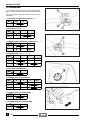
1.7 TABELLA LUBRIFICANTI
0
SUPERBIKE 4, SAE 5W - 40.
Olio motore (consigliato):
In alternativa agli olî consigliati, si possono utilizzare olî di marca con prestazioni conformi o superiori alle specifiche
CCMC G-4, A.P.I. SG.
0
0
Olio forcella (consigliato): olio per forcelle
F.A. 5W oppure
F.A. 20W.
Qualora si intendesse disporre di un comportamento intermedio tra quelli offerti da
sono miscelare i prodotti come sotto indicato:
SAE 10W
F.A. 5W 67% del volume, +
F.A. 20W 33% del volume
SAE 15W
F.A. 5W 33% del volume, +
F.A. 20W 67% del volume
0
0
0
0
0 F.A. 5W e da 0 F.A. 20W, si pos-
0
Cuscinetti e altri punti di lubrificazione (consigliato):
AUTOGREASE MP.
In alternativa al prodotto consigliato, utilizzare grasso di marca per cuscinetti volventi, campo di temperatura utile -30
°C…+140 °C, punto di gocciolamento 150 °C…230 °C, elevata protezione anticorrosiva, buona resistenza all’acqua e
all’ossidazione.
Protezione poli batteria: Grasso neutro oppure vaselina.
Grasso spray per catene (consigliato):
Liquido freni (consigliato):
a
0 CHAIN SPRAY.
0 F.F., DOT 5 (Compatibile DOT 4)
Impiegare solo liquido freni nuovo.
Liquido refrigerante motore (consigliato):
a
0 ECOBLU - 40 °C.
Impiegare solo antigelo e anticorrosivo senza nitrito, che assicuri una protezione almeno ai -35 °C.
1 - 16
INFORMAZIONI GENERALI / INFORMACIONES GENERALES / GENERAL INFORMATION
1.7 TABLA LUBRICANTES
0
SUPERBIKE 4, SAE 5W - 40.
Aceite motor (aconsejado):
En sustitución al aceite aconsejado pueden utilizarse aceites de marca con prestaciones conformes o superiores a las especificaciones CCMC G-4, A.P.I. SG.
0
0
F.A. 5W o
F.A. 20W.
Aceite horquilla (aconsejado): aceite para horquillas
En caso de que se quiera conseguir un comportamiento intermedia entre las ofrecidas por
20W, pueden mezclarse los productos según lo indicado a continuación:
F.A. 5W 67% del volumen, +
F.A. 20W 33% del volumen.
SAE 10W
F.A. 5W 33% del volumen, +
F.A. 20W 67% del volumen.
SAE 15W
0
0
0
0
0 F.A. 5W y por 0 F.A.
0
AUTOGREASE MP.
Cojinetes y otros puntos de lubricación (aconsejado):
En sustitución al producto aconsejado, utilice grasa de marca para cojinetes rodantes, campo de temperatura útil
-30˚C…+140˚C, punto de goteo 150˚C…230˚C, elevada protección antioxidante, buena resistencia al agua y a la oxidación.
Protección polos batería: Grasa neutra o vaselina.
Grasa spray para cadenas (aconsejada):
Líquido frenos (aconsejado):
0 CHAIN SPRAY.
0 F.F., DOT 5 (Compatible DOT 4).
a
Utilice sólo líquido frenos nuevo.
Líquido refrigerante del motor (aconsejado):
0 ECOBLU -40˚C.
a
Utilice sólo anticongelante y antioxidante sin nitrito que garantice una protección por lo menos a los
-35˚C.
1.7 LUBRICANT CHART
0
SUPERBIKE 4, SAE 5W-40.
Engine oil (recommended):
As an alternative to the recommended oil, it is possible to use high-quality oils with characteristics in compliance with or
superior to the CCMC G-4, A.P.I. SG specifications.
0
0
F.A. 5W or
F.A. 20 W.
Fork oil (recommended): fork oil
If you need an oil with intermediate characteristics in comparison with the two recommended products, these can be mixed
as indicated below:
F.A. 5W 67% of the volume, +
F.A. 20W 33% of the volume.
SAE 10W
F.A. 5W 33% of the volume, +
F.A. 20W 67% of the volume.
SAE 15W
0
0
0
0
0
AUTOGREASE MP.
Bearings and other lubrication points (recommended):
As an alternative to the recommended product, use high-quality grease for rolling bearings, working temperature range -30
˚C…+140 ˚C, dripping point 150 ˚C…230 ˚C, high protection against corrosion, good resistance to water and oxidation.
Protection of the battery poles: neutral grease or Vaseline.
Spray grease for chains (recommended):
Brake fluid (recommended):
0 CHAIN SPRAY.
0 F.F., DOT 5 (compatible with DOT 4).
a
Use new brake fluid only.
a
Use only antifreeze and anticorrosive without nitrite, ensuring protection at -35 ˚C at least.
Engine coolant (recommended):
0 ECOBLU -40 ˚C.
1 - 17
INFORMAZIONI GENERALI / INFORMACIONES GENERALES / GENERAL INFORMATION
NOTE / NOTES / ANMERKUNGEN
1 - 18
1
OPERAZIONI DI MANUTENZIONE
PERIODICA E DI MESSA A PUNTO
OPERACIONES DE MANTENIMIENTO
PERIÓDICO Y DE PUESTA A PUNTO
2
3
SERVICE AND SETTING UP
4
5
6
7
8
,1',&(*(1(5$/(
,1',&(*(1(5$/
7$%/(2)&217(176
2 -5
OPERAZIONI DI MANUTENZIONE PERIODICA E DI MESSA A PUNTO
OPERAZIONI DI MANUTENZIONE
INDICE
GENERAL
PERIODICA
E DI MESSA A PUNTO
2
INDICE
1
2
3
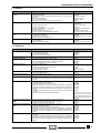
2.1 PIANO PER LA MANUTENZIONE
PERIODICA ..............................................Pag. 2-4
2.1.1 SCHEDA
DI MANUTENZIONE PERIODICA ........Pag. 2-5
2.2 PUNTI DA LUBRIFICARE .....................Pag. 2-6
2.3 BATTERIA ................................................Pag. 2-8
2.3.1 CONTROLLO LIVELLO
ELETTROLITA ....................................Pag. 2-10
2.3.2 RICARICA BATTERIA ........................Pag. 2-10
2.3.3 LUNGA INATTIVITÀ
DELLA BATTERIA..............................Pag. 2-10
2.4 CANDELA................................................Pag. 2-12
4
2.5 REGOLAZIONE DEL MINIMO............Pag. 2-14
2.6 REGOLAZIONE
COMANDO ACCELERATORE ............Pag. 2-14
2.7 FILTRO ARIA .........................................Pag. 2-16
5
6
2.8 FILTRO ARIA SCATOLA CINGHIA
TRASMISSIONE....................................Pag. 2-16
2.9 VERIFICA LIVELLO
OLIO MOTORE E RABBOCCO ..........Pag. 2-18
2.10 SOSTITUZIONE OLIO MOTORE
E FILTRO OLIO MOTORE.................Pag. 2-20
2.11 CONTROLLO LIVELLO
OLIO TRASMISSIONE.......................Pag. 2-22
2.12 SOSTITUZIONE
OLIO TRASMISSIONE.......................Pag. 2-22
7
8
2.13 FRENI A DISCO ..................................Pag. 2-24
2.13.1 CONTROLLO LIVELLO
LIQUIDO FRENI ................................Pag. 2-24
2.13.2 RABBOCCO LIQUIDO FRENI..........Pag. 2-24
2.13.3 VERIFICA USURA PASTIGLIE ........Pag. 2-26
2.14 SPURGO ARIA
IMPIANTO FRENANTE .....................Pag. 2-28
2.15 CONTROLLO E RABBOCCO
LIQUIDO REFRIGERANTE ...............Pag. 2-30
2.16 SOSTITUZIONE
LIQUIDO REFRIGERANTE ...............Pag. 2-32
2.17 CONTROLLO
E REGOLAZIONE STERZO ..............Pag. 2-34
2.17.1 CONTROLLO
GIOCO CUSCINETTI ........................Pag. 2-34
2.17.2 REGOLAZIONE
GIOCO CUSCINETTI ........................Pag. 2-34
2.18 CONTROLLO
ASSE FULCRO MOTORE..................Pag. 2-36
2.19 ISPEZIONE
SOSPENSIONE ANTERIORE...........Pag. 2-36
2.20 ISPEZIONE
SOSPENSIONE POSTERIORE ........Pag. 2-36
2.21 RUOTE / PNEUMATICI .....................Pag. 2-38
2.21.1 ISPEZIONE RUOTE ..........................Pag. 2-38
2.21.2 PNEUMATICI ....................................Pag. 2-38
2.22 COPPIE DI SERRAGGIO...................Pag. 2-40
2 -2
OPERACIONES DE MANTENIMIENTO PERIODICO Y DE
PUESTA A PUNTO
OPERACIONES DE MANTENIMIENTO
PERIODICO Y DE PUESTA A PUNTO
SERVICE AND SETTING UP
SERVICE AND SETTING UP
2
2
INDICE
TABLE OF CONTENTS
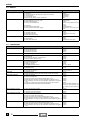
2.1 PLANPARAELMANTENIMIENTOPERIODICO
Pag. 2-4
2.1.1 FICHA DE MANTENIMIENTO
PERIODICO .......................................... Pag. 2-5
2.1 PERIODIC SERVICE
INTERVALS PLAN ................................. Pag. 2-4
2.1.1 REGULAR SERVICE
INTERVALS CHART............................. Pag. 2-5
2.2 PUNTOS A LUBRICAR.......................... Pag. 2-6
2.2 LUBRICATING POINTS ........................ Pag. 2-6
2.3 BATERIA................................................... Pag. 2-9
2.3.1 CONTROL NIVEL ELECTROLITO..... Pag. 2-11
2.3.2 RECARGA BATERIA ......................... Pag. 2-11
2.3.3 LARGA INACTIVIDAD
DE LA BATERIA ................................ Pag. 2-11
2.4 BUJIA ...................................................... Pag. 2-13
2.3 BATTERY ................................................. Pag. 2-9
2.3.1 CHECKING THE ELECTROLYTE
LEVEL ................................................. Pag. 2-11
2.3.2 RECHARGING THE BATTERY.......... Pag. 2-11
2.3.3 LONG INACTIVITY
OF THE BATTERY ............................. Pag. 2-11
2.5 AJUSTE DEL RALENTI....................... Pag. 2-15
2.4 SPARK PLUG ........................................ Pag. 2-13
2.6 AJUSTE MANDO ACELERADOR...... Pag. 2-15
2.5 IDLING ADJUSTMENT ....................... Pag. 2-15
2.7 FILTRO AIRE ......................................... Pag. 2-17
2.6 ADJUSTING THE ACCELERATOR CONTROL
Pag. 2-15
2.8 FILTROAIRECAJACORREADE TRANSMISION
Pag. 2-17
2.8 DRIVING BELT CASING
AIR CLEANER ....................................... Pag. 2-17
2.10 SUSTITUCION ACEITE MOTOR
Y FILTRO ACEITE MOTOR ............. Pag. 2-21
2.9 CHECKING THE ENGINE
OIL LEVEL AND TOPPING UP ......... Pag. 2-19
2.11 CONTROL NIVEL ACEITE
TRANSMISION ................................... Pag. 2-23
2.10 CHANGING THE ENGINE
OIL AND THE OIL FILTER............... Pag. 2-21
2.12 SUSTITUCION ACEITE
TRANSMISION ................................... Pag. 2-23
2.11 CHECKING THE
TRANSMISSION OIL LEVEL ........... Pag. 2-23
2.13 FRENOS DE DISCO ........................... Pag. 2-25
2.13.1 CONTROL NIVEL LIQUIDO
FRENOS ........................................... Pag. 2-25
2.13.2 RELLENO LIQUIDO FRENOS ......... Pag. 2-25
2.13.3 COMPROBACION DESGASTE
PASTILLAS ...................................... Pag. 2-27
2.12 CHANGING THE
TRANSMISSION OIL ......................... Pag. 2-23
2.14 PURGA AIRE SISTEMA
DE FRENADO ...................................... Pag. 2-29
2.13 DISC BRAKES..................................... Pag. 2-25
2.13.1 CHECKING THE BRAKE
FLUID LEVEL ................................... Pag. 2-25
2.13.2 TOPPING UP .................................... Pag. 2-25
2.13.3 CHECKING THE BRAKE
PAD WEAR....................................... Pag. 2-27
2.15 CONTROL
RELLENO
Y
LIQUIDO REFRIGERANTE
Pag. 2-31
2.14 BLEEDING
THE BRAKING SYSTEM .................. Pag. 2-29
2.16 SUSTITUCION LIQUIDO
REFRIGERANTE................................. Pag. 2-33
2.15 CHECKING THE COOLANT
LEVEL AND TOPPING UP ............... Pag. 2-31
2.17 CONTROL Y AJUSTE
DE LA DIRECCION ............................ Pag. 2-35
2.17.1 CONTROL JUEGO COJINETES...... Pag. 2-35
2.17.2 AJUSTE JUEGO COJINETES ......... Pag. 2-35
2.16 CHANGING THE COOLANT............ Pag. 2-33
2.19 INSPECCION SUSPENSION
DELANTERA........................................ Pag. 2-37
2.20 INSPECCION SUSPENSION
TRASERA ............................................. Pag. 2-37
2.21 RUEDAS/NEUMATICOS ................... Pag. 2-39
2.21.1 INSPECCION RUEDAS.................... Pag. 2-39
2.21.2 NEUMATICOS ...................................... Pag. 2-39
2.22 PARES DE APRIETE ......................... Pag. 2-40
2
3
4
2.7 AIR CLEANER ....................................... Pag. 2-17
2.9 COMPROBACION NIVEL
ACEITE MOTOR Y RELLENO ........... Pag. 2-19
2.18 CONTROL EJE TRANSMISION
MOTOR ................................................. Pag. 2-37
1
2.17 CHECKING AND ADJUSTING
THE STEERING .................................. Pag. 2-35
2.17.1 CHECKING THE BEARING
SLACKS ........................................... Pag. 2-35
2.17.2 ADJUSTING THE BEARING
SLACKS ........................................... Pag. 2-35
2.18 CHECKING THE ENGINE
FULCRUM AXIS ................................. Pag. 2-37
2.19 INSPECTING THE FRONT
SUSPENSION...................................... Pag. 2-37
2.20 INSPECTING THE REAR
SUSPENSION...................................... Pag. 2-37
2.21 WHEELS/TYRES................................. Pag. 2-39
2.21.1 INSPECTING THE WHEELS............ Pag. 2-39
2.21.2 TYRES .............................................. Pag. 2-39
2.22 DRIVING TORQUES .......................... Pag. 2-40
2 -3
5
6
7
8
OPERAZIONI DI MANUTENZIONE PERIODICA E DI MESSA A PUNTO / OPERACIONES DE MANTENIMIENTO PERIODICO
Y DE PUESTA A PUNTO / SERVICE AND SETTING UP
Questa sezione descrive le procedure d’intervento per la manutenzione
periodica dei principali componenti
del veicolo.
Esta sección describe los procedimientos de intervención para el mantenimiento periódico de los principales componentes del vehículo.
a
Antes de empezar cualquier tipo de intervención
de mantenimiento o de inspección al vehículo, pare el motor,
y quite la llave, espere a que el
motor y el sistema de escape se
hayan enfriado, levante el vehículo posiblemente por medio del
equipo adecuado, sobre una superficie sólida y llana. Ponga cuidado sobre todo en las partes muy
calientes del motor y del sistema
de escape, para evitar quemaduras.
Prima di iniziare qualsiasi
intervento di manutenzione
o ispezione al veicolo, fermare il motore e togliere la chiave,
attendere che motore e impianto
di scarico si siano raffreddati, sollevare possibilmente il veicolo con
apposita attrezzatura, su di un terreno solido e in piano.
Porre particolare attenzione alle
parti ancora calde del motore e
dell’impianto di scarico, in modo
tale da evitare ustioni.
c
Se non espressamente descritto, il rimontaggio dei
gruppi segue in senso inverso le
operazioni di smontaggio.
2.1 PIANO PER LA
MANUTENZIONE
PERIODICA
Per mantenere ottimali le condizioni
di funzionamento del veicolo, aprilia
raccomanda di rispettare gli intervalli
previsti per gli interventi di manutenzione periodica ai vari componenti.
2 -4
a
c
De no resultar expresamente descrito, hay que
instalar los grupos siguiendo en
orden contrario las operaciones
que se han efectuado para el desmontaje.
2.1 PLAN PARA EL
MANTENIMIENTO
PERIODICO
Para que las condiciones del vehículo sigan manteniéndose óptimas,
aprilia le recomienda respete los intervalos previstos para las intervenciones de mantenimiento periódico
en los distintos componentes.
This section describes the procedures for the periodic service on the
main components of the vehicle.
a
Before beginning any
maintenance operation or
any inspection of the vehicle, stop the engine, extract the
key from the ignition block, wait
until the engine and the exhaust
system have cooled down and if
possible lift the vehicle by means
of the proper equipment, on firm
and flat ground.
Keep away from the red-hot parts
of the engine and of the exhaust
system, in order to avoid burns.
c
If not expressly indicated
otherwise, for the reassembly of the units repeat the disassembly operations in the reverse
order.
2.1 PERIODIC SERVICE INTERVALS PLAN
aprilia recommends to respect the
intervals indicated for the periodic
service on the various components,
in order to ensure the best operating
conditions of the vehicle.
OPERAZIONI DI MANUTENZIONE PERIODICA E DI MESSA A PUNTO / OPERACIONES DE MANTENIMIENTO PERIODICO
Y DE PUESTA A PUNTO / SERVICE AND SETTING UP
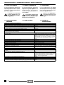
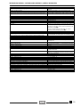
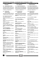
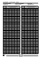
2.1.1 SCHEDA DI MANUTENZIONE
PERIODICA
2.1.1 FICHA DE MANTENIMIENTO
PERIODICO
COMPONENTI
COMPONENTES
COMPONENT
Ammortizzatori posteriori / Amortiguadores traseros /
Rear shock absorbers
Batteria-Livello elettrolita / Batería-Nivel electrólito /
Battery-Electrolyte level
Candela / Bujía / Spark plug
Carburatore - regime del minimo / Carburador-régimen del ralentí /
Carburettor - idling
Cinghia trasmissione
Correa transmisión
Transmission belts
Cuscinetti cannotto sterzo / Cojinetes manguito dirección /
Steering column bearings
Ogni 6000 km o 8 mesi
Ogni 12000 km o 16 mesi
Fine rodaggio
Fin rodaje
Cada 6000 km o 8 meses Cada 12000 km o 16 meses
After running-in
Every 6000 km or
Every 12000 km or
(1000 km)
8 mounths
16 mounths
C
C
C
C
C
S
R
C
S
C
Cuscinetti ruote / Cojinetes ruedas / Wheel bearings
P
S
Filtro variatore / Filtro variador / Variator grease
Funzionamento acceleratore / Funcionamiento acelerador /
Accelerator operation
Funzionamento bloccaggio freni / Funcionamiento bloqueo frenos /
Brake locking operation
C
C
Filtro aria / Filtro aire / Air cleaner
Filtro olio motore / Filtro aceite motor / Engine oil filter
2.1.1 REGULAR SERVICE
INTERVALS CHART
S
P
C
C
C
C
R
R
Ganasce frizione / Zapatas embrague / Clutch shoes
Gioco valvole / Juego válvulas / Valve clearance
C
Grasso variatore / Grasa variador / Variator filter
S
Interruttore luce stop / Interruptor luz stop / Stop light switch
C
Liquido freni / Líquido frenos / Brake fluid
C
ogni 6000 km: C / ogni anno : S
cada 6000 km: C / cada año : S
every 6000 km: C / every year : S
Liquido refrigerante / Líquido refrigerante / Coolant
C
ogni 2000 km: C / ogni 16 mesi : S
cada 2000 km: C / cada 16 mes : S
every 2000 km: C / every 16 month : S
Olio motore / Aceite motor / Engine oil
S
ogni 1000 km: C / ogni 6000 km: S
ogni 1000 km: C / ogni 6000 km: S
ogni 1000 km: C / ogni 6000 km: S
Olio sospensione anteriore / Aceite suspensión delantera /
Front suspension oil
C
C
S
Olio trasmissione / Aceite transmisión / Transmission oil
S
C
S
Orientamento luci-funzionamento / Orientación luces-funcionamiento /
Light direction-operation
Pneumatici-pressione di gonfiaggio / Neumáticos-presión de hinchado /
Tyres - inflation pressure
Retino filtro olio motore e vite magnetica /
Redecilla filtro aceite motor y tornillo magnético /
Engine oil filter grid and magnetic screw
Rulli variatore e guide plastica variatore /
Rodillos variador y guías plástico variador /
Variator rollers and variator plastic guides
C
ogni mese / cada mes / every month : C
C
C
Ruote - pneumatici / Ruedas - neumáticos / Wheels - tyres
Serraggio dadi, bulloni, viti / Par de apriete tuercas, pernos, tornillos /
Nut, bolt, screw tightening
Serraggio dadi testa motore / Par de apriete tuercas culata motor /
Engine head nut tightening
S
C
C
C
C
Sospensione anteriore / Suspensión delantera / Front suspension
C
Spurgo liquido freni / Purga líquido frenos / Brake fluid bleeding
C
Tubazione carburante / Tubos combustible / Fuel pipe
Usura pastiglie freni / Desgaste pastillas frenos / Brake pad wear
C
C
C
C
ogni 4 anni / cada 4 años
/ every 4 years : S
ogni / cada / every 2000 km: C
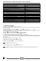
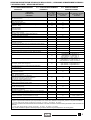
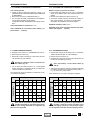
C = controllare e pulire, regolare, lubrificare o sostituire se necessario; P = pulire; S = sostituire; R = regolare.
Eseguire le operazioni di manutenzione più’ frequentemente se il veicolo viene utilizzato in zone piovose, polverose o su percorsi accidentati.
C = controle, limpie, ajuste, lubrique o sustituya si es necesario; P = limpie; S = sustituya; R = ajuste.
Realice las operaciones de mantenimiento más frecuentemente si se utiliza el vehículo en zonas lluviosas, polvorientas o sobre recorridos accidentados.
C = check, clean, adjust, lubricate or change, if necessary; P = clean; S = change; R = adjust.
Carry out the maintenance operations more frequently if you use the vehicle in rainy and dusty areas or on uneven ground.
2 -5
OPERAZIONI DI MANUTENZIONE PERIODICA E DI MESSA A PUNTO / OPERACIONES DE MANTENIMIENTO PERIODICO
Y DE PUESTA A PUNTO / SERVICE AND SETTING UP
2.2 PUNTI DA LUBRIFICARE
2.2 PUNTOS A LUBRICAR
2.2 LUBRICATING POINTS
Una lubrificazione corretta è importante per un funzionamento scorrevole e una lunga durata dei componenti in movimento del veicolo.
Una lubricación correcta es importante para un funcionamiento deslizante y una larga duración de los
componentes en movimiento del vehículo.
Correct lubrication is important for
the good operation and long life of
the moving parts of the vehicle.
c
Prima della lubrificazione,
ripulire completamente
ogni parte di eventuale ruggine e
rimuovere tutto il grasso, la sporcizia e la polvere.
Le parti esposte che sono soggette alla ruggine, devono essere lubrificate con olio motore o grasso,
vedi 1.7 (TABELLA LUBRIFICANTI).
Nella “SCHEDA DI LUBRIFICAZIONE” sono riportati i punti da lubrificare.
LEGENDA SCHEDA DI LUBRIFICAZIONE
1)
2)
3)
4)
5)
6)
7)
8)
Perno leva freno
Cuscinetti sterzo
Perno cavalletto laterale
Perno cavalletto centrale
Comando acceleratore
Cavo acceleratore
Cavo tachimetro-contachilometri
Comando tachimetro-contachilometri
9) Perno ruota posteriore
2 -6
c
Antes de lubricar, limpie
completamente cada parte
de eventual herrumbre y quite
toda la grasa, la suciedad y el polvo.
Hay que lubricar con aceite motor
o con grasa las partes expuestas
que están sometidas a la herrumbre, véase 1.7 (TABLA LUBRICANTES).
En la “FICHA DE LUBRICACION”
están señalados los puntos que
hay que lubricar.
PIE DE LA FIGURA FICHA DE LUBRICACION
1)
2)
3)
4)
5)
6)
7)
Perno palanca freno
Cojinetes de la dirección
Perno caballete lateral
Perno caballete central
Mando acelerador
Cable acelerador
Cable
taquímetro-cuentakilómetros
8) Mando
taquímetro-cuentakilómetros
9) Perno rueda trasera
Before lubrication, remove rust,
grease, dirt and dust completely.
It is advisable to lubricate the
parts that are subject to rusting
with engine oil or grease, see 1.7
(LUBRICANT CHART).
The points that need lubricating
are indicated in the “LUBRICATION CHART”.
LUBRICATION CHART KEY
1)
2)
3)
4)
5)
6)
7)
8)
9)
Brake lever pin
Steering bearings
Side stand pin
Central stand pin
Accelerator control
Accelerator cable
Speedometer-odometer cable
Speedometer-odometer control
Rear wheel pin
OPERAZIONI DI MANUTENZIONE PERIODICA E DI MESSA A PUNTO / OPERACIONES DE MANTENIMIENTO PERIODICO
Y DE PUESTA A PUNTO / SERVICE AND SETTING UP
SCHEDA DI LUBRIFICAZIONE
FICHA DE LUBRICACION
LUBRICATION CHART
■ = Grasso
▲ = Olio
■ = Grasa
▲ = Aceite
■ = Grease
▲ = Oil
2 -7
OPERAZIONI DI MANUTENZIONE PERIODICA E DI MESSA A PUNTO
2.3 BATTERIA
Leggere attentamente 1.4 (PRECAUZIONI E INFORMAZIONI GENERALI).
Dopo i primi 1000 km e ogni 6000 km, controllare il livello
dell’elettrolita e il serraggio dei morsetti.
a
L'elettrolita della batteria è tossico, caustico,
e a contatto con l'epidermide può causare
ustioni in quanto contiene acido solforico. Indossare abiti protettivi, una maschera per il viso e/o
occhiali nel caso di manutenzione.
a
Se del liquido elettrolitico venisse a contatto
con la pelle, lavare con abbondante acqua
corrente.
Se venisse a contatto con gli occhi, lavare con acqua
abbondante per quindici minuti, quindi rivolgersi
tempestivamente a un oculista.
Se viene ingerito accidentalmente, bere abbondanti
quantità di acqua o latte, continuare con latte di magnesia od olio vegetale, quindi rivolgersi prontamente a un medico.
La batteria emana gas esplosivi, è opportuno tenere
lontane fiamme, scintille, sigarette e qualsiasi altra
fonte di calore.
Durante la ricarica o l'uso, provvedere a un'adeguata
ventilazione del locale, evitare l'inalazione dei gas
emessi durante la ricarica della stessa.
a
a
Non invertire mai il collegamento dei cavi della batteria.
Porre attenzione a non inclinare troppo il veicolo onde evitare pericolose fuoriuscite del liquido della batteria.
TENERE LONTANO DALLA PORTATA DEI BAMBINI.
a
Collegare e scollegare la batteria con l’interruttore di accensione in posizione “m”.
Collegare prima il cavo positivo (+) e poi quello negativo (–).
Scollegare seguendo l’ordine inverso.
a
Il liquido della batteria è corrosivo.
Non versarlo o spargerlo, in particolare sulle
parti in plastica.
2 -8
OPERACIONES DE MANTENIMIENTO PERIODICO Y DE
PUESTA A PUNTO
SERVICE AND SETTING UP
2.3 BATERIA
2.3 BATTERY
Lea con mucho cuidado 1.4 (PRECAUCIONES E INFORMACIONES GENERALES).
Carefully read 1.4 (PRECAUTIONS AND GENERAL INFORMATION)
Controle tras los primeros 1000 km y cada 6000 km el nivel del electrólito y el apretamiento de los bornes.
Check the electrolyte level and the tightening of the terminals after the first 1000 km and then every 6000 km.
El electrólito de la batería es tóxico, cáustico
y en contacto con la epidermis puede causar
quemaduras por contener ácido sulfúrico.
Lleve ropa protectora, una máscara para la cara y/o
gafas en el caso de mantenimiento.
a
The electrolyte in the battery is toxic and
caustic and if it gets in contact with the skin it
can cause burns, since it contains sulphuric
acid. Wear protection clothes, a face mask and/or
goggles during maintenance operations.
Si algo del líquido electrolítico viniera a contacto con
la piel, lávese con abundante agua corriente.
In case of contact with the skin, rinse with plenty of
water.
De llegar a contacto con los ojos, lávese con abundante agua durante quince minutos, luego diríjase
enseguida a un oculista.
In case of contact with the eyes, rinse with plenty of
water for 15 minutes, then consult an oculist without
delay.
De tragarlo accidentalmente, beba mucha agua o leche, siga con leche de magnesia o aceite vegetal, luego diríjase enseguida a un médico.
If the electrolyte is accidentally swallowed, drink a lot
of water or milk, then continue drinking milk of magnesia or vegetable oil and consult a doctor without
delay.
La batería emana gases explosivos, por lo tanto es
conveniente mantener lejos llamas, chispas, cigarrillos y cualquier otra fuente de calor.
Durante la recarga o el uso, provea a una ventilación
adecuada del local, evite la inhalación de gases emitidos durante la recarga de la misma.
a
a
No invierta nunca la conexión de los cables
de la batería.
Ponga cuidado en no inclinar demasiado el
vehículo, para evitar salidas peligrosas del líquido de la batería.
MANTENGASE LEJOS DEL ALCANCE DE LOS NIÑOS.
a
a
The battery gives off explosive gases; keep it away
from flames, sparks, cigarettes and any other source
of heat.
During the recharging or the use, make sure that the
room is properly ventilated and avoid inhaling the
gases released during the recharging.
a
a
Never invert the connection of the battery cables.
Do not incline the vehicle too much, in order
to avoid dangerous leaks of the battery fluid.
KEEP AWAY FROM CHILDREN.
a
Conecte y desconecte la batería con el interruptor de encendido en posición “m”.
Conecte antes el cable positivo (+) y luego el
negativo (–).
Desconecte siguiendo el orden contrario.
Connect and disconnect the battery with the
ignition switch in position “m”.
Connect first the positive cable (+) and then
the negative cable (–).
Disconnect following the reverse order.
a
a
El líquido de la batería es corrosivo.
No lo vierta ni lo esparza, sobre todo sobre las
partes de plástico.
The electrolyte is corrosive.
Take care not to pour or spill it, especially on
the plastic parts.
2 -9
OPERAZIONI DI MANUTENZIONE PERIODICA E DI MESSA A PUNTO
2.3.1 CONTROLLO LIVELLO ELETTROLITA
Leggere attentamente 2.3 (BATTERIA).
Per il controllo del livello dell'elettrolita è necessario:
◆ Sollevare la sella.
◆ Svitare e togliere le due viti (1).
◆ Rimuovere il coperchio batteria (2).
◆ Controllare che il livello del liquido sia compreso fra le
due tacche “MIN” e “MAX”, stampigliate sul lato della
batteria. Eventualmente ripristinare il livello aggiungendo acqua distillata.
Non superare il riferimento “MAX”, in quanto il livello
aumenta durante la ricarica.
2.3.2 RICARICA BATTERIA
Leggere attentamente 2.3 (BATTERIA).
◆
◆
◆
◆
◆
◆
◆
◆
Assicurarsi che l’interruttore di accensione sia in posizione “m”.
Controllare con un tester la tensione della batteria.
Se la tensione è inferiore a 12 V la batteria deve essere ricaricata.
Scollegare nell’ordine il cavo negativo (–) (3) e quello
positivo (+) (4).
Rimuovere il tubetto sfiato batteria.
Rimuovere la batteria dall’alloggiamento e sistemarla
in un luogo fresco e asciutto.
Svitare e togliere i tappi degli elementi.
È consigliata una ricarica utilizzando un amperaggio di
1/10 della capacità della batteria stessa.
A ricarica avvenuta, ricontrollare il livello dell’elettrolita
ed eventualmente rabboccare con acqua distillata.
a
Dopo la ricarica controllare la densità
dell’elettrolita utilizzando un densitometro.
Sostituire la batteria se in qualche vano la
densità è inferiore a 1,26 e la tensione a vuoto è inferiore a 12V.
◆
◆
◆
Serrare i tappi degli elementi.
Posizionare la batteria nel suo alloggiamento.
Collegare il tubetto sfiato batteria.
a
Collegare sempre lo sfiato della batteria, per
evitare che i vapori di acido solforico, uscendo dallo sfiato, possano corrodere l’impianto
elettrico, le parti verniciate, i particolari in gomma o
le guarnizioni.
◆
Collegare nell’ordine il cavo positivo (+) (4) e quello
negativo (–) (3).
2.3.3 LUNGA INATTIVITÀ DELLA BATTERIA
Leggere attentamente 2.3 (BATTERIA).
Nel caso in cui il veicolo rimanga inattivo per un lungo periodo, rimuovere la batteria e sistemarla in un luogo fresco
e asciutto. Ricaricarla completamente, utilizzando una ricarica lenta.
Se la batteria rimane sul veicolo, scollegare i cavi dai terminali.
È importante controllare la carica periodicamente (circa
una volta al mese), nei periodi invernali o quando il veicolo
rimane fermo, per evitarne il degrado.
2 - 10
OPERACIONES DE MANTENIMIENTO PERIODICO Y DE
PUESTA A PUNTO
SERVICE AND SETTING UP
2.3.1 CONTROL NIVEL ELECTROLITO
2.3.1 CHECKING THE ELECTROLYTE LEVEL
Lea con cuidado 2.3 (BATERIA).
Carefully read 2.3 (BATTERY).
Para el control del nivel del electrólito hay que:
To check the electrolyte level, proceed as follows:
◆
◆
◆
◆
Levantar el sillín.
Destornillar y quitar los dos tornillos (1).
Quitar la tapa batería (2).
Controlar que el nivel del líquido esté entre las dos
muescas “MIN” y “MAX” , impresas sobre el lado de la
batería. Eventualmente, restaure el nivel añadiendo
agua destilada.
No supere la referencia “MAX” , ya que el nivel aumenta durante la recarga.
◆
◆
◆
◆
Raise the saddle.
Unscrew and remove the two screws (1).
Remove the battery cover (2).
Make sure that the fluid level is included between the
two “MIN” and “MAX” notches stamped on the battery
side. If necessary, top up by adding distilled water.
Never exceed the “MAX” notch, since the level increases during the recharge.
2.3.2 RECARGA BATERIA
2.3.2 RECHARGING THE BATTERY
Lea con cuidado 2.3 (BATERIA).
Carefully read 2.3 (BATTERY).
◆
◆
◆
◆
◆
◆
◆
◆
Controle que el interruptor de encendido esté en posición “m”.
Controle con un tester la tensión de la batería.
Hay que recargar la batería si la tensión es inferior a
12 V.
Desconecte antes el cable negativo (–) (3) y luego el
positivo (+) (4).
Extraiga el tubo respiradero batería.
Saque la batería de su alojamiento y colóquela en un
lugar fresco y seco.
Destornille y quite los tapones de los elementos.
Se aconseja una recarga utilizando un amperaje de
1/10 de la capacidad de la misma batería.
Tras haber realizado la recarga, controle el nivel del
electrólito y de resultar necesario rellene con agua
destilada.
a
Tras la recarga controle la densidad del electrólito utilizando un densímetro. Sustituya la
batería si en uno de los vanos la densidad es
inferior a 1,26 y la tensión en vacío es inferior a 12V.
◆
◆
◆
◆
◆
◆
◆
◆
a
After recharging, check the density of the
electrolyte by means of a densimeter. Change
the battery if in any of the battery compartments the density of the electrolyte is lower than 1,26
and the no-load voltage is lower than 12V.
◆
◆
◆
◆
Apriete los tapones de los elementos.
Coloque la batería en su alojamiento.
Conecte el tubo respiradero batería.
a
Conecte siempre el respiradero de la batería
para evitar que los vapores del ácido sulfúrico, al salir del respiradero, puedan corroer la
instalación eléctrica, las partes barnizadas, los detalles de goma o las juntas.
◆
◆
Conecte antes el cable positivo (+) (4) y luego el negativo (–) (3).
Tighten the element plugs.
Put back the battery in its container.
Connect the battery breather pipe.
a
Always connect the battery breather pipe, to
prevent the sulphuric acid vapours from corroding the electric system, painted parts, rubber elements or gaskets when they exit the breather
pipe itself.
◆
◆
Make sure that the ignition switch is in position “m”.
Check the battery voltage by means of a tester.
If the voltage is lower than 12V, the battery needs
recharging.
Disconnect, in order, the negative (–) (3) and positive
(+) (4) cable.
Remove the battery breather pipe.
Extract the battery from its container and put it in a cool
and dry place.
Unscrew and remove the element plugs.
A recharge with an amperage equal to 1/10th of the
battery capacity is recommended.
After the recharging operation, check the electrolyte
level again and if necessary top up with distilled water.
Connect, in order, the positive (+) (4) and negative (–)
(3) cable.
2.3.3 LARGA INACTIVIDAD DE LA BATERIA
2.3.3 LONG INACTIVITY OF THE BATTERY
Lea con cuidado 2.3 (BATERIA).
Carefully read 2.3 (BATTERY).
En caso de que el vehículo quede inactivo durante una
larga temporada, saque la batería y colóquela en un lugar fresco y seco. Recárguela completamente, usando
una recarga lenta.
Si la batería queda en el vehículo, desconecte los cables
de los terminales.
Es importante controlar la carga periódicamente (más o
menos una vez cada mes) durante el invierno o cuando
el vehículo se queda parado, para evitar que pueda degradarse.
If the vehicle remains unused for a long period, remove
the battery and place it in a cool and dry place. Recharge
it completely, by using a trickle charge.
If the battery remains on the vehicle, disconnect the cables from the terminals.
It is important to check the charge periodically (about
once a month), during the winter or when the vehicle remains unused, in order to prevent the deterioration of the
battery.
2 - 11
OPERAZIONI DI MANUTENZIONE PERIODICA E DI MESSA A PUNTO
2.4 CANDELA
Leggere attentamente 1.4 (PRECAUZIONI E INFORMAZIONI GENERALI).
Sostituire la candela ogni 6000 chilometri.
Smontare periodicamente la candela, pulirla dalle incrostazioni carboniose e sostituirla, se necessario.
Per accedere alla candela:
◆
Rimuovere il coperchio di ispezione sinistro, vedi 7.1.2
(RIMOZIONE COPERCHI DI ISPEZIONE DESTRO E
SINISTRO).
Per la rimozione e la pulizia:
◆
◆
◆
◆
◆
◆
◆
Disinserire la pipetta della candela (1).
Togliere ogni traccia di sporco dalla base della candela, quindi svitarla con la chiave in dotazione al kit attrezzi ed estrarla dalla sede, avendo cura di non far
entrare polvere o altre sostanze all’interno del cilindro.
Controllare che l’elettrodo e la porcellana centrale della candela siano privi di depositi carboniosi o segni di
corrosione, eventualmente pulire con gli appositi pulitori per candele, con un filo di ferro e/o spazzolino metallico.
Soffiare energicamente con un getto d’aria per evitare
che i residui rimossi entrino nel motore.
Se la candela presenta screpolature sull’isolante, elettrodi corrosi o eccessivi depositi, deve essere sostituita.
La gradazione termica è corretta se entrambi gli isolanti sono di colore marrone chiaro. Se gli isolanti risultano anneriti dai depositi carboniosi, utilizzare candele
con grado termico inferiore.
Se l’isolante si presenta bianco, sostituire la candela
con altra di grado termico superiore.
Le candele con elevato grado termico sono usate per
marcia ad alta velocità. Sono concepite per avere un
sufficiente raffreddamento e prevenire il surriscaldamento e sono chiamate candele di tipo “freddo”.
Controllare la distanza tra gli elettrodi con uno spessimetro.
Questa deve essere di 0,6 mm, eventualmente regolarla, piegando con cautela l’elettrodo di massa.
Accertarsi che la rondella sia in buone condizioni.
Con la rondella montata, avvitare a mano la candela
per evitare di danneggiare la filettatura.
Serrare con la chiave in dotazione al kit attrezzi, facendo compiere 1/2 giro alla candela per comprimere la
rondella.
a
La candela deve essere ben avvitata, altrimenti il motore si potrebbe surriscaldare, danneggiandosi gravemente.
Utilizzare solo candele del tipo consigliato, vedi 1.6
(CARATTERISTICHE TECNICHE); altrimenti si potrebbero compromettere le prestazioni e la durata del
motore.
a
Quando si sostituisce la candela, controllare il
passo e la lunghezza della filettatura. Se la
parte filettata è troppo corta, i depositi carboniosi si depositeranno sulla sede della filettatura, rischiando così di danneggiare il motore.
◆
◆
Posizionare correttamente la pipetta della candela, in
modo che non si stacchi con le vibrazioni del motore.
Rimontare il coperchio di ispezione.
2 - 12
NGK
Standard
Tipo freddo
Tipo caldo
CR8E
CR9E
CR7E
OPERACIONES DE MANTENIMIENTO PERIODICO Y DE
PUESTA A PUNTO
SERVICE AND SETTING UP
2.4 BUJIA
2.4 SPARK PLUG
Lea con cuidado 1.4 (PRECAUCIONES E INFORMACIONES GENERALES).
Carefully read 1.4 (PRECAUTIONS AND GENERAL INFORMATION)
Sustituya la bujía cada 6000 km.
Desmonte periódicamente la bujía, límpiela de las incrustaciones de carbonilla y sustitúyala si es necesario.
Change the spark plug every 6000 km.
Periodically remove the spark plug and clean it carefully,
removing carbon deposits; change it if necessary.
Para acceder a la bujía:
To reach the spark plug:
◆
Quite la tapa de inspección izquierda, véase 7.1.2
(DESMONTAJE TAPAS DE INSPECCION DERECHA
E IZQUIERDA).
◆
Remove the left inspection cover, see 7.1.2 (REMOVING THE RIGHT AND LEFT INSPECTION COVERS).
Para el desmontaje y la limpieza:
◆
◆
◆
◆
Desconecte la pipeta de la bujía (1).
Limpie muy bien la base de la bujía, luego destorníllela
utilizando la llave que forma parte del equipamiento
base del kit herramientas, y extráigala de su sede, teniendo cuidado que polvo u otras sustancias no entren
en el interior del cilindro.
Controle que sobre el electrodo y sobre la porcelana
central de la bujía no haya costras de carbonilla o signos de corrosión. Eventualmente, limpie con los limpiadores adecuados para bujías, con un alambre y/o
con un cepillo metálico.
Sople muy fuerte con un chorro de aire para evitar que
residuos removidos entren en el motor. Hay que sustituir la bujía si ésta presenta hendiduras en el aislador,
electrodos oxidados o incrustaciones excesivas.
La gradación térmica es correcta si ambos aislantes
son de color marrón claro. En caso de que los aislantes resulten ennegrecidos por las costras de carbonilla, utilice bujía con grado térmico inferior.
Si el aislante se presenta de color blanco, sustituya la
bujía con otra con grado térmico superior.
Las bujías con elevado grado térmico se utilizan para
marcha a alta velocidad. Han sido construidas para tener un suficiente enfriamiento y para prevenir el sobrecalentamiento y se llaman bujías de tipo “frío”.
NGK
◆
◆
◆
Standard
Tipo frío
Tipo caliente
CR8E
CR9E
CR7E
Controle la distancia entre los electrodos por medio de
un calibre de espesor.
Esta tiene que ser de 0,6 mm, si acaso ajústela curvando con cuidado el electrodo de masa.
Compruebe que la arandela esté en buenas condiciones. Con la arandela instalada, atornille a mano la bujía para no dañar la rosca.
Apriete con la llave del kit herramientas del equipamiento base, dándole 1/2 vuelta a la bujía, para comprimir la arandela.
To remove and clean the spark plug:
◆
◆
◆
◆
Take off the spark plug cap (1).
Remove all the dirt from the base of the spark plug,
then unscrew it with the spanner you will find in the tool
kit and extract it from its seat, taking care that neither
dust nor other substances enter the cylinder.
Make sure that there are neither carbon deposits, nor
corrosion marks on the electrode and on the central
porcelain part ; if necessary, clean them with the special cleaners for spark plugs, with an iron wire and/or a
metal brush.
Energetically blow some air, in order to prevent the removed residues from getting into the engine.
If the spark plug has crackings on the insulating material, corroded electrodes or excessive deposits, it must
be changed. The thermal rating is correct if both the insulating materials are light brown. If they tend to be
black due to carbon deposits, use spark plugs with
lower thermal rating.
If the insulating material is white, change the spark
plug with a new one having higher thermal rating.
Spark plugs with high thermal rating are used for high
speeds. They are designed in order to ensure sufficient cooling and avoid overheating and are called
“cold” plugs.
NGK
◆
◆
◆
Standard
Cold type
Hot type
CR8E
CR9E
CR7E
Check the spark plug gap with a thickness gauge.
The gap must be 0,6 mm; if necessary adjust it, carefully bending the earth electrode.
Make sure that the washer is in good conditions.
With the washer on, screw the spark plug by hand in
order not to damage the thread.
Tighten the spark plug by means of the spanner you
will find in the tool kit, giving it half a turn to compress
the washer.
a
a
The spark plug must be well tightened, otherwise the engine may overheat and be seriously damaged.
Use the recommended type of spark plug only, see
1.6 (CARATTERISTICHE TECNICHE), in order not to
reduce the life and performance of the engine.
a
When replacing the spark plug, check the
pitch and length of the thread. If the threaded
part is too short, carbon deposits will settle
on the thread seat, which may result in damages to
the engine.
Hay que atornillar muy bien la bujía para que
el motor no se sobrecaliente, dañándose gravemente.
Utilice sólo bujías del tipo aconsejado, véase 1.6 (CARATTERISTICHE TECNICHE) para no perjudicar el
rendimiento y la duración del motor.
Cuando se sustituye la bujía, controle el paso
y la longitud de la rosca. Si la parte roscada es
demasiado corta, las costras de carbonilla se
van a depositar sobre la sede de la rosca, con el riesgo, de tal manera, de dañar el motor.
◆
◆
Instale correctamente la pipeta de la bujía de manera
que no se despegue con las vibraciones del motor.
Vuelva a instalar la tapa de inspección.
a
◆
◆
Position the spark plug cap properly, so that it does not
come off due to the vibrations of the engine.
Put back the inspection cover.
2 - 13
OPERAZIONI DI MANUTENZIONE PERIODICA E DI MESSA A PUNTO
2.5 REGOLAZIONE DEL MINIMO
Leggere attentamente 1.4 (PRECAUZIONI E INFORMAZIONI GENERALI).
Eseguire la regolazione del minimo ogniqualvolta risulti
irregolare.
Per effettuare questa operazione:
◆
◆
◆
◆
◆
◆
Far funzionare il motore sino al raggiungimento della
temperatura di normale funzionamento.
Posizionare il veicolo sul cavalletto centrale.
Rimuovere il coperchio di ispezione sinistro, vedi 7.1.2
(RIMOZIONE COPERCHI DI ISPEZIONE DESTRO E
SINISTRO).
Collegare un contagiri elettronico al cavo della candela.
Intervenire sulla vite di registro (1), posta sul carburatore.
AVVITANDO (senso orario), il numero di giri aumenta.
SVITANDO (senso antiorario), il numero di giri diminuisce.
Il regime di rotazione minimo del motore dovrà essere
di circa 1600 ± 100 giri/min, in questo caso la ruota posteriore non viene posta in rotazione dal motore.
Agendo sulla manopola acceleratore, accelerare e decelerare alcune volte per controllare il corretto funzionamento e se il minimo rimane stabile.
c
Non intervenire sulla vite di regolazione aria,
onde evitare variazioni sulla taratura della carburazione.
2.6 REGOLAZIONE COMANDO
ACCELERATORE
Leggere attentamente 1.4 (PRECAUZIONI E INFORMAZIONI GENERALI).
Il gioco ottimale del comando acceleratore deve essere di
circa 2 - 3 mm.
Per la regolazione:
◆
◆
◆
Sfilare la cuffia di protezione (2).
Allentare (avvitandolo) il dado (3).
Agire sul registro (4), situato all’ingresso del cavo comando acceleratore.
Al termine della regolazione, serrare (svitandolo) il dado
(3) bloccando il registro (4) e posizionare la cuffia di protezione (2).
2 - 14
OPERACIONES DE MANTENIMIENTO PERIODICO Y DE
PUESTA A PUNTO
SERVICE AND SETTING UP
2.5 AJUSTE DEL RALENTI
2.5 IDLING ADJUSTMENT
Lea con cuidado 1.4 (PRECAUCIONES E INFORMACIONES GENERALES).
Carefully read 1.4 (PRECAUTIONS AND GENERAL INFORMATION)
Ajuste el ralentí cada vez que resulte irregular.
Adjust the idling every time it is irregular.
Para realizar esta operación:
To carry out this operation, proceed as follows:
◆
◆
◆
◆
◆
◆
Haga funcionar el motor hasta que alcance la temperatura normal de funcionamiento.
Coloque el vehículo sobre el caballete central.
Quite la tapa de inspección izquierda, véase 7.1.2
(DESMONTAJE TAPAS DE INSPECCION DERECHA
E IZQUIERDA).
Conecte un cuentarrevoluciones electrónico al cable
de la bujía.
Actúe sobre el tornillo de regulación (1) colocado sobre el carburador.
ATORNILLANDO (en sentido horario) aumenta el número de las revoluciones.
DESTORNILLANDO (en sentido antihorario) disminuye el número de las revoluciones.
El régimen mínimo de las revoluciones del motor tendrá que ser de unas 1600 ± 100 rpm; en este caso la
rueda trasera no está puesta en rotación por el motor.
Actuando sobre el puño de gas, acelere y decelere algunas veces para controlar el funcionamiento correcto
y si el ralentí queda estable.
c
No actúe sobre el tornillo de regulación aire
para evitar variaciones en la regulación de la
carburación.
◆
◆
◆
◆
◆
◆
Warm the engine up until it reaches the normal running
temperature.
Position the vehicle on the stand.
Remove the left inspection cover, see 7.1.2 (REMOVING THE RIGHT AND LEFT INSPECTION COVERS).
Connect an electronic revolution counter to the spark
plug cable.
Adjust the screw (1) positioned on the carburettor.
By SCREWING IT (clockwise), you increase the engine rpm.
By UNSCREWING IT (anticlockwise), you decrease
the engine rpm.
The minimum speed of the engine (idling) must be
about 1600 ± 100 rpm; in this case the engine does not
make the rear wheel rotate.
Twist the throttle grip, accelerating and decelerating a
few times to make sure that it functions correctly and
to check if the idling speed is constant.
c
Do not act on the air adjusting screw, to avoid
variations of the carburation setting.
2.6 AJUSTE MANDO ACELERADOR
2.6 ADJUSTING THE ACCELERATOR CONTROL
Lea con cuidado 1.4 (PRECAUCIONES E INFORMACIONES GENERALES).
El juego óptimo del mando acelerador ha de ser de unos
2-3 mm.
Carefully read 1.4 (PRECAUTIONS AND GENERAL INFORMATION)
The ideal slack of the accelerator control should be about
2-3 mm.
Para el ajuste:
◆
◆
◆
Extraiga el elemento de protección (2).
Afloje (atornillándola) la tuerca (3).
Actúe sobre el regulador (4) colocado en la entrada
del cable mando acelerador.
Tras haber realizado el ajuste, apriete (destornillándola)
la tuerca (3) bloqueando el regulador (4) y coloque el elemento de protección (2).
To adjust the slack, proceed as follows:
◆
◆
◆
Remove the protection element (2).
Loosen the nut (3) (by screwing it).
Act on the adjuster (4) placed at the beginning of the
accelerator control cable.
Once you have carried out the adjustment, tighten the nut
(3) (by unscrewing it), thus locking the adjuster (4) and
put back the protection element (2).
2 - 15
OPERAZIONI DI MANUTENZIONE PERIODICA E DI MESSA A PUNTO
2.7 FILTRO ARIA
Leggere attentamente 1.4 (PRECAUZIONI E INFORMAZIONI GENERALI).
a
Non usare benzina o solventi infiammabili per
il lavaggio dell’elemento filtrante, per evitare il
rischio di incendi o di esplosioni.
La pulizia e il controllo dello stato del filtro dell’aria devono essere effettuati ogni 6000 km.
Se il veicolo viene usato su strade polverose o bagnate,
le operazioni di pulizia o sostituzione dovranno essere
eseguite più frequentemente.
Per la rimozione:
◆
◆
◆
◆
Posizionare il veicolo sul cavalletto centrale.
Svitare e togliere le cinque viti (1).
Rimuovere il coperchio cassa filtro (2), il filtro (3) e la
retina (4).
Controllare la guarnizione cassa filtro; eventualmente
sostituirla.
Per la pulizia dell’elemento filtrante, utilizzare solventi
puliti, non infiammabili o con alto punto di volatilità e
farlo asciugare completamente.
Applicare su tutta la superficie un olio per filtri o un olio
denso (SAE 80 W - 90), quindi strizzarlo per eliminare
l’eccesso di olio.
c
Il filtro deve essere ben impregnato ma non
gocciolante.
2.8 FILTRO ARIA SCATOLA CINGHIA
TRASMISSIONE
Leggere attentamente 1.4 (PRECAUZIONI E INFORMAZIONI GENERALI).
a
Non fare uso di benzina o solventi infiammabili per il lavaggio dell’elemento filtrante, per
evitare il rischio di incendi o di esplosioni.
La pulizia e il controllo dello stato del filtro aria della scatola della cinghia devono essere effettuati ogni 6000 km.
Se il veicolo viene usato su strade polverose o bagnate,
le operazioni di pulizia o sostituzione dovranno essere
eseguite più frequentemente.
Per la rimozione:
◆
◆
◆
◆
Posizionare il veicolo sul cavalletto centrale.
Svitare e togliere le tre viti (5).
Rimuovere il coperchio del filtro (6) e il filtro (7).
Per la pulizia dell’elemento filtrante, utilizzare solventi
puliti, non infiammabili o con alto punto di volatilità e
farlo asciugare completamente.
a
NON OLIARE L’ELEMENTO FILTRANTE, altrimenti l’olio, entrando nella scatola della cinghia, potrebbe danneggiarla o farla slittare.
2 - 16
OPERACIONES DE MANTENIMIENTO PERIODICO Y DE
PUESTA A PUNTO
SERVICE AND SETTING UP
2.7 FILTRO AIRE
2.7 AIR CLEANER
Lea con cuidado 1.4 (PRECAUCIONES E INFORMACIONES GENERALES).
Carefully read page 1.4 (PRECAUTIONS AND GENERAL INFORMATION)
a
a
No use gasolina o disolventes inflamables
para lavar el elemento filtrante para evitar el
riesgo de incendios o explosiones.
Do not use petrol or inflammable solvents to
wash the air cleaner, in order to avoid fires or
explosions.
Limpie y controle las condiciones del filtro del aire cada
6000 km.
De utilizar el vehículo en carreteras llenas de polvo o mojadas, las operaciones de limpieza o de sustitución tendrán que efectuarse con mayor frecuencia.
Check the conditions of the air cleaner and clean it every
6000 km.
If the vehicle is used on dusty or wet roads, the cleaning
operations and any replacement should be carried out
more frequently.
Para el desmontaje:
To remove the filter, proceed as follows:
◆
◆
◆
◆
Coloque el vehículo sobre el caballete central.
Destornille y quite los cinco tornillos (1).
Quite la tapa caja filtro (2), el filtro (3) y la redecilla (4).
Controle la junta caja filtro y si acaso sustitúyala.
Para limpiar el elemento filtrante utilice disolventes
limpios, no inflamables o con alto punto de volatilidad
y déjelo secar del todo.
Aplique sobre toda la superficie un aceite para filtros o
un aceite espeso (SAE 80W - 90); luego escúrralo
para eliminar el exceso de aceite.
c
El filtro debe quedar bien impregnado pero no
debe gotear.
2.8 FILTRO AIRE CAJA CORREA
DE TRANSMISION
Lea con cuidado 1.4 (PRECAUCIONES E INFORMACIONES GENERALES).
a
No use gasolina o disolventes inflamables
para lavar el elemento filtrante, para evitar el
riesgo de incendios o explosiones.
Limpie y controle las condiciones del filtro aire de la caja
de la correa cada 6000 km.
De utilizar el vehículo en carreteras llenas de polvo o mojadas, las operaciones de limpieza tendrán que efectuarse con mayor frecuencia.
◆
◆
◆
◆
Position the vehicle on the stand.
Unscrew and remove the five screws (1).
Remove the filter case cover (2), the filter (3) and the
grid (4).
Check the filter case seal and if necessary change it.
To clean the filtering element use clean, non-inflammable solvents or solvents with high volatility point,
then let it dry thoroughly.
Apply a filter oil or a thick oil (SAE 80W - 90) on the
whole surface of the filtering element, then squeeze it
to eliminate the oil in excess.
c
The filter must be well impregnated, though
not dripping.
2.8 DRIVING BELT CASING AIR CLEANER
Carefully read 1.4 (PRECAUTIONS AND GENERAL INFORMATION).
a
Do not use petrol or inflammable solvents to
wash the air cleaner, in order to avoid fires or
explosions.
Check the conditions of the belt casing air cleaner and
clean it every 6000 km.
If the vehicle is used on dusty or wet roads, the cleaning
operations and any replacement should be carried out
more frequently.
To remove the filter, proceed as follows:
Para el desmontaje:
◆
◆
◆
◆
Coloque el vehículo sobre el caballete central.
Destornille y quite los tres tornillos (5).
Quite la tapa del filtro (6) y el filtro (7).
Para limpiar el elemento filtrante utilice disolventes
limpios, no inflamables o con alto punto de volatilidad
y déjelo secar del todo.
a
NO ENGRASE EL ELEMENTO FILTRANTE,
porque en caso contrario el aceite, entrando
en la caja de la correa, podría dañarla o hacerla deslizar.
◆
◆
◆
◆
Position the vehicle on the stand.
Unscrew and remove the three screws (5).
Remove the filter cover (6) and the filter (7).
To clean the filtering element use clean, non-inflammable solvents or solvents with high volatility point,
then let it dry thoroughly.
a
DO NOT OIL THE FILTERING ELEMENT, since
the oil may penetrate the belt casing and damage the belt or make it slip.
2 - 17
OPERAZIONI DI MANUTENZIONE PERIODICA E DI MESSA A PUNTO
2.9 VERIFICA LIVELLO OLIO MOTORE E
RABBOCCO
NON DISPERDERE L’OLIO NELL’AMBIENTE.
Leggere attentamente 1.2.2 (OLIO MOTORE) e 1.4
(PRECAUZIONI E INFORMAZIONI GENERALI).
Controllare il livello olio motore ogni 1000 km, sostituirlo
ogni 6000 km, vedi 2.10 (SOSTITUZIONE OLIO MOTORE E FILTRO OLIO MOTORE).
Per il controllo:
◆
◆
Spegnere il motore e lasciarlo raffreddare almeno dieci
minuti, per consentire il drenaggio dell’olio nel carter e
il raffreddamento dell’olio stesso.
Tenere il veicolo in posizione verticale con le due ruote
appoggiate al suolo.
c
Se non si eseguono le precedenti operazioni, si rischia di effettuare un’errato rilevamento del livello.
◆
◆
◆
◆
◆
◆
Rimuovere il coperchio di ispezione destro, vedi 7.1.2
(RIMOZIONE COPERCHI DI ISPEZIONE DESTRO E
SINISTRO).
Svitare ed estrarre il tappo-astina di misura (1).
Pulire la parte a contatto con l’olio con un panno pulito.
Inserire completamente senza avvitarlo, il tappo-astina
nel foro di immissione (2).
Estrarre nuovamente il tappo-astina e leggere il livello
raggiunto dall’olio sull’astina:
MAX = livello massimo
MIN = livello minimo.
La differenza tra “MAX” e “MIN” è di circa 150 cmC.
Il livello è corretto se raggiunge approssimativamente
il livello “MAX”, segnato sull’astina di misura.
a
◆
Non oltrepassare la marcatura “MAX” e non
andare al di sotto della marcatura “MIN”, per
non causare gravi danni al motore.
Se necessario, ripristinare il livello dell’olio motore attraverso il foro d’immissione (2), dopo aver rimosso il
tappo-astina di misura (1).
2 - 18
OPERACIONES DE MANTENIMIENTO PERIODICO Y DE
PUESTA A PUNTO
SERVICE AND SETTING UP
2.9 COMPROBACION NIVEL ACEITE MOTOR
Y RELLENO
2.9 CHECKING THE ENGINE OIL LEVEL AND
TOPPING UP
NO ESPARZA EL ACEITE EN EL AMBIENTE.
DO NOT DISPOSE OF ENGINE OIL IN THE ENVIRONMENT.
Lea con cuidado 1.2.2 (ACEITE MOTOR) y 1.4 (PRECAUCIONES E INFORMACIONES GENERALES).
Controle el nivel aceite motor cada 1000 km, sustitúyalo
cada 6000 km, véase 2.10 (SUSTITUCION ACEITE MOTOR Y FILTRO ACEITE MOTOR).
Carefully read 1.2.2 (ENGINE OIL) and 1.4 (PRECAUTIONS AND GENERAL INFORMATION)
Check the engine oil level every 1000 km, change it every
6000 km, see 2.10 (CHANGING THE ENGINE OIL AND
THE OIL FILTER).
Para el control:
◆
◆
Apague el motor y déjelo enfriar unos diez minutos por
lo menos para permitir el drenaje del aceite en el cárter y el enfriamiento del aceite mismo.
Mantenga el vehículo en posición vertical con las dos
ruedas apoyadas en el suelo.
c
De no realizar las operaciones anteriores la
medición del nivel puede resultar no correcta.
◆
◆
◆
◆
◆
◆
Quite la tapa de inspección derecha, véase 7.1.2 (DESMONTAJE TAPAS DE INSPECCION DERECHA E
IZQUIERDA).
Destornille y extraiga el tapón-varilla de medida (1).
Limpie la parte en contacto con el aceite utilizando un
paño limpio.
Introduzca del todo y sin enroscarlo el tapón-varilla en
el orificio de introducción (2).
Extraiga otra vez el tapón-varilla y lea en la varilla el nivel alcanzado por el aceite.
MAX = nivel máximo.
MIN = nivel mínimo.
La diferencia entre “MAX” y “MIN” es de unos 150 cmC.
El nivel es correcto si alcanza aproximadamente el nivel “MAX” , indicado en la varilla de medida.
a
◆
To carry out the checking:
◆
◆
c
The non-performance of the operations described above may result in a wrong measurement of the level.
◆
◆
◆
◆
◆
◆
No supere la muesca “MAX” ni vaya por debajo de la muesca “MIN”, para no causar graves
daños al motor.
De resultar necesario, restaure el nivel del aceite motor a través del orificio de introducción (2), tras haber
quitado el tapón-varilla de medida (1).
Stop the engine and let it cool down for at least 10 minutes, in order to allow the oil to flow back to the oil pan
and to cool down.
Keep the vehicle in vertical position, with the two
wheels resting on the ground.
Remove the right inspection cover, see 7.1.2 (REMOVING THE RIGHT AND LEFT INSPECTION COVERS).
Unscrew and extract the plug/dipstick (1).
Clean the part in contact with the oil with a clean cloth.
Insert the plug/dipstick in the relevant hole (2) completely, without tightening it.
Withdraw the plug/dipstick again and read the oil level
on the graduated marking:
MAX = maximum level.
MIN = minimum level.
The difference between “MAX” and “MIN” is about
150 cmC.
The level is correct if the oil reaches approx. the “MAX”
marking on the dipstick.
a
◆
Never exceed the “MAX” marking, nor leave
the oil below the “MIN” marking, in order to
avoid serious damages to the engine.
If necessary, top up the engine oil tank through the filling hole (2), after extracting the plug/dipstick (1).
2 - 19
OPERAZIONI DI MANUTENZIONE PERIODICA E DI MESSA A PUNTO
2.10 SOSTITUZIONE OLIO MOTORE E FILTRO
OLIO MOTORE
NON DISPERDERE L’OLIO NELL’AMBIENTE.
Leggere attentamente 1.2.2 (OLIO MOTORE) e 1.4
(PRECAUZIONI E INFORMAZIONI GENERALI).
Controllare il livello olio motore ogni 1000 km, sostituirlo
ogni 6000 km.
Per la sostituzione:
◆
◆
Spegnere il motore e lasciarlo raffreddare almeno dieci
minuti, per consentire il drenaggio dell’olio nel carter e
il raffreddamento dell’olio stesso.
Posizionare il veicolo sul cavalletto centrale.
a
Il motore riscaldato contiene olio ad alta temperatura, porre p a r t i c o l a r e a t t e n z i o n e a
n o n scottarsi durante lo svolgimento delle
operazioni successive.
◆
◆
◆
◆
◆
◆
◆
Rimuovere il coperchio di ispezione destro, vedi 7.1.2
(RIMOZIONE COPERCHI DI ISPEZIONE DESTRO E
SINISTRO).
Svitare ed estrarre il tappo-astina di misura (1).
Posizionare un contenitore con capacità non inferiore
a 1300 cmC, sotto il basamento, in corrispondenza del
tappo di scarico (3).
Svitare e togliere il tappo di scarico (3).
Scaricare l’olio all’interno del contenitore e lasciarlo
gocciolare per alcuni minuti, all’interno del contenitore.
Rimuovere i residui metallici attaccati alla calamita del
tappo di scarico (3).
Svitare e togliere il tappo filtro di fondo (4) e pulire il filtro di fondo da eventuali residui.
Effettuare la sostituzione del filtro dell’olio motore
ogni 6000 km (od ogni cambio d’olio).
◆
◆
◆
◆
◆
◆
◆
◆
◆
◆
◆
Svitare le due viti (5) e togliere il coperchietto (6).
Rimuovere il filtro olio motore e sostituirlo.
Stendere un velo d’olio sull’anello di tenuta del nuovo
filtro olio.
Rimontare il coperchietto (6) e serrare le due viti (5).
Controllare la rondella di tenuta del tappo di scarico
(3), riavvitare il tappo e serrarlo.
Controllare la rondella di tenuta del tappo filtro di fondo
(4), riavvitare il tappo e serrarlo.
Versare dall’apertura di riempimento (2) 900 cmC circa
di olio motore, vedi 1.7 (TABELLA LUBRIFICANTI).
Avvitare il tappo-astina (1).
Avviare il motore e lasciarlo funzionare al minimo fino
allo spegnimento della spia pressione olio motore
“j”.
Arrestare il motore e controllare il livello dell’olio (con il
veicolo posizionato sul cavalletto centrale), vedi 2.9
(VERIFICA LIVELLO OLIO MOTORE E RABBOCCO).
A questo punto sarà necessario aggiungere altri 200
cmC di olio, per raggiungere approssimativamente il livello “MAX”.
2 - 20
OPERACIONES DE MANTENIMIENTO PERIODICO Y DE
PUESTA A PUNTO
SERVICE AND SETTING UP
2.10 SUSTITUCION ACEITE MOTOR
Y FILTRO ACEITE MOTOR
2.10 CHANGING THE ENGINE OIL AND THE
OIL FILTER
NO ESPARZA EL ACEITE EN EL AMBIENTE
DO NOT DISPOSE OF THE ENGINE OIL IN THE ENVIRONMENT.
Lea con cuidado 1.2.2 (ACEITE MOTOR) y 1.4 (PRECAUCIONES E INFORMACIONES GENERALES).
Controle el nivel aceite motor cada 1000 km, sustitúyalo
cada 6000 km.
Carefully read 1.2.2 (ENGINE OIL) and 1.4 (PRECAUTIONS AND GENERAL INFORMATION)
Check the engine oil level every 1000 km and change it
every 6000 km.
Para la sustitución:
◆
◆
Apague el motor y déjelo enfriar unos 10 minutos por
lo menos, para permitir el drenaje del aceite en el cárter y el enfriamiento del aceite mismo.
Coloque el vehículo sobre el caballete central.
a
◆
◆
◆
◆
◆
◆
◆
◆
◆
◆
◆
◆
◆
◆
◆
◆
◆
◆
◆
El motor caliente contiene aceite a altas temperaturas, ponga cuidado en no quemarse durante el desarrollo de las operaciones sucesivas.
Quite la tapa de inspección derecha, véase 7.1.2 (DESMONTAJE TAPAS DE INSPECCION DERECHA E
IZQUIERDA).
Desenrosque y extraiga el tapón-varilla de medida (1).
Coloque un recipiente con capacidad no inferior a
1300 cmC, por debajo de la base, en correspondencia
con el tapón de vaciado (3).
Desenrosque y quite el tapón de vaciado (3).
Descargue el aceite dentro del recipiente y déjelo gotear por unos minutos dentro del recipiente.
Quite los residuos metálicos pegados al imán del tapón de vaciado (3).
Desenrosque y quite el tapón filtro del fondo (4) y limpie el filtro del fondo de eventuales residuos.
Sustituya el filtro del aceite motor cada 6000 km (o
cada vez que se cambia el aceite).
◆
To change the oil, proceed as follows:
Destornille los dos tornillos (5) y quite la tapa (6).
Saque el filtro aceite motor y sustitúyalo.
Aplique una ligera capa de aceite sobre el aro tórico
del nuevo filtro aceite.
Vuelva a instalar la tapa (6) y apriete los dos tornillos
(5).
Controle la arandela de junta del tapón de vaciado (3),
enrosque y apriete el tapón.
Controle la arandela de junta del tapón filtro del fondo
(4), enrosque y apriete el tapón.
Vierta en la abertura de llenado (2) unos 900 cmC de
aceite motor, véase 1.7 (TABLA LUBRICANTES).
Enrosque el tapón - varilla (1).
Ponga en marcha el motor y déjelo funcionar al ralentí
hasta que se apague la luz indicadora presión aceite
motor “j”.
Pare el motor y controle el nivel del aceite (con el vehículo sobre el caballete central), véase 2.9 (COMPROBACION NIVEL ACEITE MOTOR Y RELLENO).
A este punto será necesario añadir otros 200 cmC de
aceite para alcanzar aproximadamente el nivel “MAX”.
Stop the engine and let it cool down for at least 10 minutes, in order to allow the oil to flow back to the oil pan
and to cool down.
Position the vehicle on the central stand.
a
When warmed up, the engine contains hot oil;
therefore, while carrying out the operations
described here below be particularly careful,
in order to avoid burns.
◆
◆
◆
◆
◆
◆
◆
Remove the right inspection cover, see 7.1.2 (REMOVING THE RIGHT AND LEFT INSPECTION COVERS).
Unscrew and extract the plug/dipstick (1).
Put a container with at least 1300 cmC capacity under
the base, in correspondence with the drain plug (3).
Unscrew and remove the drain plug (3).
Drain the oil and let it drip into the container for a few
minutes.
Remove the metal residues from the drain plug magnet (3).
Unscrew and remove the bottom filter plug (4) and remove any residue from the bottom filter.
Change the engine oil filter every 6000 km (or every
time you change the oil).
◆
◆
◆
◆
◆
◆
◆
◆
◆
◆
◆
Unscrew the two screws (5) and remove the cover (6).
Remove the engine oil filter and change it.
Spread an oil film on the sealing ring of the new oil filter.
Put back the cover (6) and tighten the two screws (5).
Check the sealing washer of the drain plug (3), screw
the plug and tighten it.
Check the sealing washer of the bottom filter plug (4),
screw the plug and tighten it.
Pour about 900 cmC of engine oil through the filling
opening (2), see 1.7 (LUBRICANT CHART).
Tighten the plug/dipstick (1).
Start the engine and let it run idly until the engine oil
pressure warning light “j” goes off.
Stop the engine and check the oil level (with the vehicle resting on the central stand), see 2.9 (CHECKING
THE ENGINE OIL LEVEL AND TOPPING UP).
At this point it will be necessary to add other 200 cmC of
oil, in order to reach approximately the “MAX” marking.
2 - 21
OPERAZIONI DI MANUTENZIONE PERIODICA E DI MESSA A PUNTO
2.11 CONTROLLO LIVELLO OLIO
TRASMISSIONE
NON DISPERDERE L’OLIO NELL’AMBIENTE
Leggere attentamente 1.4 (PRECAUZIONI E INFORMAZIONI GENERALI).
Per effettuare il controllo livello olio trasmissione, effettuare le seguenti operazioni, ogni 6000 km di percorrenza
od ogni 8 mesi:
◆
◆
◆
◆
◆
◆
◆
Percorrere qualche chilometro sino al raggiungimento
della temperatura normale di funzionamento, quindi
arrestare il motore.
Posizionare il veicolo sul cavalletto centrale.
Posizionare un recipiente graduato con capacità non
inferiore a 100 cmC, sotto il tappo di scarico (1).
Svitare il tappo di carico (2) e quello di scarico (1).
Lasciar fuoriuscire completamente l’olio dal carter, misurare la quantità; se questa fosse inferiore a 90 cmC,
ripristinare il livello aggiungendo la quantità mancante,
vedi 1.7 (TABELLA LUBRIFICANTI).
Serrare il tappo di scarico (1).
Utilizzando una siringa o un sistema simile, iniettare
l’olio attraverso il foro di immissione.
c
Per facilitare il riempimento del carter, ruotare
con le mani la ruota.
◆
Avvitare e serrare il tappo di carico (2).
2.12 SOSTITUZIONE OLIO TRASMISSIONE
NON DISPERDERE L’OLIO NELL’AMBIENTE
Leggere attentamente 1.4 (PRECAUZIONI E INFORMAZIONI GENERALI).
Per una buona efficienza e durata del veicolo, effettuare
la sostituzione dell’olio dopo i primi 1000 km e successivamente ogni 12000 km od ogni 16 mesi.
◆
◆
◆
◆
Eseguire le prime quattro operazioni di 2.11 (CONTROLLO LIVELLO OLIO TRASMISSIONE).
Lasciar fuoriuscire completamente l’olio dal carter.
Serrare il tappo di scarico (1).
Utilizzando una siringa o un sistema simile, iniettare 90
cmC di olio dal foro immissione, vedi 1.7 (TABELLA
LUBRIFICANTI).
c
Per facilitare il riempimento del carter, ruotare
con le mani la ruota.
◆
Avvitare e serrare il tappo di carico (2).
a
Serrare accuratamente i tappi di carico e scarico e assicurarsi che l’olio non trafili.
Controllare periodicamente che non ci siano perdite
in corrispondenza della guarnizione del coperchio
del carter.
Non utilizzare il veicolo con lubrificazione insufficiente o con lubrificanti contaminati o impropri, in quanto
accelerano il logorio delle parti in movimento e possono dar luogo a danni irreparabili.
2 - 22
OPERACIONES DE MANTENIMIENTO PERIODICO Y DE
PUESTA A PUNTO
SERVICE AND SETTING UP
2.11 CONTROL NIVEL ACEITE TRANSMISION
2.11 CHECKING THE TRANSMISSION OIL
LEVEL
NO ESPARZA EL ACEITE EN EL AMBIENTE
Lea con cuidado 1.4 (PRECAUCIONES E INFORMACIONES GENERALES).
Para el control del nivel del aceite transmisión, hay que
efectuar las siguientes operaciones cada 6000 km de recorrido o cada 8 meses:
◆
◆
◆
◆
◆
◆
◆
Recorra algunos kilómetros hasta alcanzar la temperatura normal de funcionamiento y luego pare el motor.
Coloque el vehículo sobre el caballete central.
Coloque un recipiente graduado con capacidad no inferior a 100 cmC, por debajo del tapón de vaciado (1).
Desenrosque el tapón de llenado (2) y el tapón de vaciado (1).
Deje salir el aceite completamente del cárter, mida la
cantidad; si ésta resultara inferior a 90 cmC, restaure el
nivel añadiendo la cantidad que falta, véase 1.7 (TABLA LUBRICANTES).
Cierre el tapón de vaciado (1).
Utilizando una jeringa o un sistema semejante, inyecte
el aceite a través del orificio de introducción.
c
Para facilitar el llenado del cárter, gire la rueda con las manos.
◆
DO NOT DISPOSE OF THE TRANSMISSION OIL IN
THE ENVIRONMENT.
Carefully read 1.4 (PRECAUTIONS AND GENERAL INFORMATION)
To check the transmission oil level, carry out the following
operations every 6000 km or every 8 months:
◆
◆
◆
◆
◆
◆
◆
Drive for a few miles until the engine reaches the normal running temperature, then stop it.
Position the vehicle on the stand.
Put a graduated container with at least 100 cmC capacity under the drain plug (1).
Unscrew the filling cap (2) and the oil drain plug (1).
Let all the oil flow out of the oil pan, measure the quantity and if it is less than 90 cmC, top up by adding the
lacking quantity, see 1.7 (LUBRICANT CHART).
Tighten the drain plug (1).
Inject the oil through the filling hole by means of a syringe or a similar system.
c
To facilitate the filling of the oil pan, rotate the
wheel with your hands.
◆
Screw and tighten the filling cap (2).
Enrosque y apriete el tapón de llenado (2).
2.12 CHANGING THE TRANSMISSION OIL
2.12 SUSTITUCION ACEITE TRANSMISION
NO ESPARZA EL ACEITE EN EL AMBIENTE
DO NOT DISPOSE OF THE TRANSMISSION OIL IN
THE ENVIRONMENT.
Lea con cuidado 1.4 (PRECAUCIONES E INFORMACIONES GENERALES)
Carefully read 1.4 (PRECAUTIONS AND GENERAL INFORMATION)
Para una buena eficiencia y duración del vehículo, sustituya el aceite tras los primeros 1000 km y sucesivamente
cada 12000 km o cada 16 meses.
To ensure the efficiency and long life of the vehicle, it is
necessary to change the oil after the first 1000 km and
successively every 12000 km or every 16 months.
◆
◆
◆
◆
Realice las cuatro primeras operaciones de 2.11
(CONTROL NIVEL ACEITE TRANSMISION).
Deje salir el aceite completamente del cárter.
Cierre el tapón de vaciado (1).
Utilizando una jeringa o un sistema semejante, inyecte
90 cmC de aceite a través del orificio de introducción,
véase 1.7 (TABLA LUBRICANTES).
c
Para facilitar el llenado del cárter, gire la rueda con las manos.
◆
Enrosque y apriete el tapón de llenado (2).
a
Cierre con cuidado los tapones de llenado y
de vaciado y controle que el aceite no se salga.
◆
◆
◆
◆
Carry out the first four operations described in 2.11
(CHECKING THE TRANSMISSION OIL LEVEL).
Let all the oil flow out of the oil pan.
Tighten the drain plug (1).
Pour 90 cmC of oil through the filling hole, by means of
a syringe or a similar system, see 1.7 (LUBRICANT
CHART).
c
To facilitate the filling of the oil pan, rotate the
wheel with your hands.
◆
Screw and tighten the filling cap (2).
a
Tighten the filling cap and the drain plug thoroughly and make sure that there are no oil
leaks.
Controle periódicamente que no haya pérdidas en
correspondencia con la junta de la tapa del cárter.
Periodically make sure that there are no leaks in correspondence with the oil pan cover seal.
No utilice el vehículo con lubricación insuficiente o
con lubrificantes contaminados o no adecuados, porque aceleran el desgaste de las partes en movimiento y pueden crear daños irreparables.
Do not use the vehicle with insufficient lubrication or
with contaminated or unsuitable lubricants, since
this would accelerate the wear of the moving parts
and may also cause irreparable failures.
2 - 23
OPERAZIONI DI MANUTENZIONE PERIODICA E DI MESSA A PUNTO
2.13 FRENI A DISCO
Leggere attentamente 1.2.5 (LIQUIDO FRENI) e 1.4
(PRECAUZIONI E INFORMAZIONI GENERALI).
a
I freni sono gli organi che garantiscono maggiormente la sicurezza, quindi devono essere
sempre mantenuti in perfetta efficienza. Il liquido freni deve essere sostituito una volta all’anno.
Questo veicolo è dotato di freni anteriori e posteriori
idraulici a disco. Col consumarsi delle pastiglie d’attrito, il
livello del liquido freni nel serbatoio diminuisce per compensarne automaticamente l’usura.
I serbatoi liquido freni sono situati sotto il coprimanubrio,
in prossimità degli attacchi leve freno.
Controllare periodicamente il livello del liquido freni nei
serbatoi, vedi 2.13.1 (CONTROLLO LIVELLO LIQUIDO
FRENI) e l’usura delle pastiglie, vedi 2.13.3 (VERIFICA
USURA PASTIGLIE).
a
Controllare l’ efficienza frenante.
Nel caso di una corsa eccessiva della leva freno, di eccessiva elasticità o nel caso di presenza di bolle d’aria nel circuito, controllare le guarnizioni e i componenti dell’impianto frenante; quindi
effettuare lo spurgo dell’aria dall’impianto, vedi 2.14
(SPURGO ARIA IMPIANTO FRENANTE).
Lo spurgo deve comunque essere effettuato dopo i
primi 1000 km.
2.13.1 CONTROLLO LIVELLO LIQUIDO FRENI
Leggere attentamente 2.13 (FRENI A DISCO).
Rimuovere gli specchietti retrovisori, vedi 7.1.9 (RIMOZIONE SPECCHIETTI RETROVISORI).
◆ Tenere il veicolo in posizione verticale e ruotare il manubrio in modo che il liquido contenuto nel serbatoio
sia parallelo al coperchio serbatoio liquido freni.
◆ Verificare che il liquido contenuto nel serbatoio superi
il riferimento “MIN” riportato sul vetrino (1).
Se il liquido non raggiunge almeno il riferimento “MIN”:
◆ Provvedere al rabbocco.
◆
2.13.2 RABBOCCO LIQUIDO FRENI
Leggere attentamente 2.13 (FRENI A DISCO).
◆
◆
Rimuovere il cupolino (2), vedi 7.1.10 (RIMOZIONE
CUPOLINO).
Svitare le due viti (3) del serbatoio liquido freni (4).
Rimuovere il coperchio (5).
c
◆
Per non spandere il liquido dei freni durante il
rabbocco, si raccomanda di mantenere il liquido nel serbatoio parallelo al bordo serbatoio (in posizione orizzontale).
c
◆
Rimuovere la guarnizione (6).
Come riferimento per ottenere il livello massimo”MAX”, rabboccare sino a coprire completemente il vetrino (1), con il bordo del serbatoio liquido freni parallelo al suolo.
a
Il rabbocco sino al livello “MAX” deve essere
effettuato solo con pastiglie nuove.
Il livello del liquido diminuisce progressivamente con l’usura delle pastiglie.
Si raccomanda di non rabboccare sino al livello
“MAX” con le pastiglie usurate, poichè si provocherà
la fuoriuscita del liquido in caso di sostituzione pastiglie freno.
◆
◆
Riempire il serbatoio (4) con liquido freni, vedi 1.7 (TABELLA LUBRIFICANTI), sino a coprire completamente il vetrino (1).
Per il rimontaggio dei componenti, seguire il procedimento inverso.
2 - 24
OPERACIONES DE MANTENIMIENTO PERIODICO Y DE
PUESTA A PUNTO
SERVICE AND SETTING UP
2.13 FRENOS DE DISCO
2.13 DISC BRAKES
Lea con cuidado 1.2.5 (LIQUIDO FRENOS) y 1.4 (PRECAUCIONES E INFORMACIONES GENERALES).
Carefully read 1.2.5 (BRAKE FLUID) and 1.4 (PRECAUTIONS AND GENERAL INFORMATION)
Los frenos son los órganos que garantizan mayormente la seguridad, por lo tanto hay que
conservarlos siempre en perfecta eficacia. Hay
que sustituir el líquido de los frenos una vez cada año.
a
The brakes are the parts that most ensure
your safety and for this reason they must always be perfectly working.
The brake fluid must be changed once a year.
Este vehículo está dotado de frenos delanteros y traseros hídraulicos de disco. Gastándose las pastillas del freno, el nivel del líquido disminuye para compensar automáticamente el desgaste. Los depósitos del líquido
frenos se encuentran debajo del cubremanillar, cerca de
los enganches palancas freno.
This vehicle is provided with front and rear hydraulic disc
brakes. When the disc pads wear out, the level of the fluid
decreases to automatically compensate for their wear.
The brake fluid tanks are positioned under the handlebar
cover, near the brake lever couplings.
Controle periódicamente el nivel del líquido frenos en los
depósitos, véase 2.13.1 (CONTROL NIVEL LIQUIDO
FRENOS) y desgaste pastillas, véase 2.13.3 (COMPROBACION DESGASTE PASTILLAS).
a
Periodically check the brake fluid level in the tanks, see
2.13.1 (CHECKING THE BRAKE FLUID LEVEL) and the
brake pad wear, see 2.13.3 (CHECKING THE BRAKE
PAD WEAR).
a
Controle la eficiencia de frenado. En caso de
una carrera excesiva de la palanca del freno,
de excesiva elasticidad o en caso de presencia
de burbujas de aire en el circuito, controle las juntas y
los componentes del sistema de frenado; luego efectúe la purga del aire del sistema, véase 2.14 (PURGA
AIRE SISTEMA DE FRENADO). De todas formas hay
que realizar la purga tras los primeros 1000 km.
a
Check the braking efficiency.
In case of excessive stroke of the brake lever,
of excessive elasticity or in case there is air in
the circuit, check the seals and the braking system
components; then bleed the system, 2.14 (BLEEDING
THE BRAKING SYSTEM).
In any case, the bleeding must be carried out after the
first 1000 km.
2.13.1 CONTROL NIVEL LIQUIDO FRENOS
2.13.1 CHECKING THE BRAKE FLUID LEVEL
Lea con cuidado 2.13 (FRENOS DE DISCO)
Carefully read 2.13 (DISC BRAKES)
Saque los retrovisores, véase 7.1.9 (DESMONTAJE
RETROVISORES).
◆ Mantenga el vehículo en posición vertical y gire el manillar de manera que el líquido contenido en el depósito
quede paralelo a la tapa del depósito del líquido frenos.
◆ Compruebe que el líquido contenido en el depósito supere la referencia “MIN” indicada en el cristal (1).
Si el líquido no llega por lo menos hasta la referencia
“MIN”:
◆ Rellene enseguida.
Remove the rear-view mirrors, see 7.1.9 (REMOVING
THE REAR-VIEW MIRRORS).
◆ Keep the vehicle in vertical position and rotate the handlebar so that the fluid contained in the tank is parallel
to the brake fluid tank cover.
◆ Make sure that the fluid level exceeds the “MIN” notch
on the glass (1).
If the fluid does not reach the “MIN” notch:
◆ Provide for topping up.
2.13.2 RELLENO LIQUIDO FRENOS
2.13.2 TOPPING UP
Lea con cuidado 2.13 (FRENOS DE DISCO).
Carefully read 2.13 (DISC BRAKES)
◆
◆
◆
Quite el elemento frontal (2), véase 7.1.10 (DESMONTAJE ELEMENTO FRONTAL).
Destornille los dos tornillos (3) del depósito del líquido
frenos (4).
Quite la tapa (5).
c
◆
Para no verter el líquido de los frenos durante
el relleno, mantenga el líquido en el depósito
paralelo al borde del depósito (en posición horizontal).
c
◆
Quite la junta (6).
Como referencia para alcanzar el nivel máximo "MAX", rellene hasta cubrir del todo el
cristal (1), con el borde del depósito líquido de los
frenos paralelo al suelo.
a
Hay que efectuar el relleno hasta el nivel
"MAX" sólo con pastillas nuevas.
El nivel del líquido disminuye progresivamente con el desgaste de las pastillas.
Se recomienda no rellene hasta el nivel "MAX" con las
pastillas desgastadas, porque en caso de sustitución
de las pastillas del freno el líquido podría salirse.
◆
◆
Llene el depósito (4) con líquido frenos, véase 1.7 (TABLA LUBRICANTES), hasta cubrir del todo el cristal (1).
Para volver a instalar los componentes, actúe siguiendo el procedimiento en orden contrario.
◆
◆
◆
Remove the front part of the fairing (2), see 7.1.10
(REMOVING THE FRONT PART OF THE FAIRING).
Unscrew the two screws (3) of the brake fluid tank (4).
Remove the cover (5).
c
◆
In order not to spill the brake fluid while topping up, keep the fluid in the reservoir parallel
to the reservoir rim (in horizontal position).
c
◆
Remove the gasket (6).
In order to reach the "MAX" level, top up until
covering the glass (1) completely, with the
brake fluid reservoir rim parallel to the ground.
a
The topping up to the "MAX" level can be carried out only with new pads.
The fluid level decreases progressively with
the pad wear.
Do not top up to the "MAX" level with worn pads,
since this may cause an outflow of liquid when the
brake pads are changed.
◆
◆
Fill the tank (4) with brake fluid, see 1.7 (LUBRICANT
CHART), until it covers the glass (1) completely.
To reassemble the components, follow the reverse order.
2 - 25
OPERAZIONI DI MANUTENZIONE PERIODICA E DI MESSA A PUNTO
2.13.3 VERIFICA USURA PASTIGLIE
Leggere attentamente 2.13 (FRENI A DISCO)
Le seguenti informazioni sono riferite a un solo impianto frenante ma sono valide per entrambi.
Controllare l’usura delle pastiglie del freno dopo i primi
1000 km, successivamente ogni 2000 km. L’usura delle
pastiglie del freno a disco dipende dall’uso, dal tipo di guida e di strada. L’usura è maggiore durante l’uso su strade
sporche o bagnate.
Per eseguire un controllo rapido dell’usura delle pastiglie:
◆
◆
Posizionare il veicolo sul cavalletto centrale.
Rimuovere il coperchio pinza freno (1).
c
Per il controllo dell’usura pastiglie freno posteriore, non è necessario rimuovere il coperchio pinza freno (1), ma è sufficiente controllare visivamente lo spessore delle pastiglie, attraverso la
pinza freno, guardando dalla parte posteriore del veicolo.
◆
Effettuare un controllo visivo tra pinza freno e pastiglie.
Se lo spessore del materiale d’attrito (anche di una
sola pastiglia) è ridotto sino al valore di circa 1 mm, sostituire entrambe le pastiglie.
2 - 26
OPERACIONES DE MANTENIMIENTO PERIODICO Y DE
PUESTA A PUNTO
SERVICE AND SETTING UP
2.13.3 COMPROBACION DESGASTE PASTILLAS
2.13.3 CHECKING THE BRAKE PAD WEAR
Lea con cuidado 2.13 (FRENOS DE DISCO).
Carefully read 2.13 (DISC BRAKES).
Las siguientes informaciones se refieren a un solo
sistema de frenado pero tienen validez incluso para
ambos.
The following information refers to a single braking
system, but is valid for both.
Controle el desgaste de las pastillas del freno después
de los primeros 1000 km; luego cada 2000 km.
El desgaste de las pastillas del freno de disco depende
del uso, del tipo de conducción y de carretera.
El desgaste es mayor cuando se conduce en carreteras
sucias o mojadas.
Para realizar un control rápido del desgaste de las pastillas hay que:
◆
◆
Colocar el vehículo sobre el caballete central.
Quitar la tapa zapatas freno (1).
c
Para controlar el desgaste pastillas freno trasero, no hace falta quitar la tapa zapatas freno
(1), sino que es suficiente controlar visualmente el
espesor de las pastillas a través de la pinza de freno,
mirando desde la parte trasera del vehículo.
◆
Efectúe un control visual entre la pinza de freno y las
pastillas. Si el espesor del material de fricción (incluso
de una sola pastilla) queda reducido al valor aproximado de 1 mm, sustituya ambas pastillas.
Check the brake pad wear after the first 1000 km and
successively every 2000 km. The wear of the brake pads
depends on the use, on the kind of drive and on the road.
The wear will be greater when the vehicle is driven on
dirty or wet roads.
To carry out a rapid checking of the wear of the pads, proceed as follows:
◆
◆
Position the vehicle on the stand.
Remove the brake calliper cover (1).
c
To check the rear brake pad wear, it is not
necessary to remove the brake calliper cover
(1), but it is sufficient to check the pad thickness visually, by looking through the brake calliper from the
rear part of the vehicle.
◆
Carry out a visual checking of the friction material
thickness by looking between the brake calliper and
the pads. If the thickness of the friction material (even
of one pad only) has reduced to about 1 mm, replace
both pads.
2 - 27
OPERAZIONI DI MANUTENZIONE PERIODICA E DI MESSA A PUNTO
2.14 SPURGO ARIA IMPIANTO FRENANTE
Leggere attentamente 2.13 (FRENI A DISCO)
L’aria, se presente nel circuito idraulico, agisce da cuscinetto assorbendo gran parte della pressione esercitata
dalla pompa freni e riducendo l’efficacia della pinza in frenata. La presenza dell’aria si manifesta: con la “spugnosità” del comando del freno e con la riduzione della capacità frenante.
a
Considerando la pericolosità per il veicolo e
per il pilota, è assolutamente indispensabile
che il circuito idraulico sia spurgato dall’aria,
dopo il rimontaggio dei freni e il ripristino dell’impianto frenante alle normali condizioni d’uso.
◆
◆
◆
Rimuovere il cupolino (1), vedi 7.1.10 (RIMOZIONE
CUPOLINO).
Svitare le due viti (2) del serbatoio liquido freni (3).
Rimuovere il coperchio (4).
c
Per non spandere il liquido dei freni durante il
rabbocco, si raccomanda di mantenere il liquido nel serbatoio parallelo al suolo.
◆
◆
◆
◆
Rimuovere la guarnizione (5).
Verificare che il livello del liquido copra completamente
il vetrino (6), rabboccare se necessario.
Rimuovere il cappuccio di protezione della valvola di
sfiato (7).
Collegare alla valvola di sfiato (8) un tubo trasparente
(9).
a
◆
◆
◆
Posizionare l’estremità libera del tubo trasparante
all’interno di un contenitore (10).
Azionare, lentamente e a fondo, la leva freno per due o
tre volte, quindi tenerla azionata.
Allentare la valvola di sfiato (8), premere la leva e controllare se dal tubo trasparente fuoriescono bolle d’aria
insieme al liquido freno.
a
◆
Non imbrattare con il liquido freno le pastiglie
o il disco.
Prima di rilasciare la leva freno, serrare la valvola di sfiato (8), per impedire all’aria di entrare nel circuito dei freni.
Quando uscirà il solo liquido freno, serrare la valvola di
sfiato (8) e rilasciare la leva freno.
Coppia di serraggio valvola di sfiato (8):
14 Nm (1,4 kgm).
c
a
Ripetere le ultime tre operazioni sino alla completa eliminazione delle bolle d’aria.
Dopo il rimontaggio, azionare ripetutamente
la leva freno e controllare il corretto funzionamento del sistema frenante.
2 - 28
OPERACIONES DE MANTENIMIENTO PERIODICO Y DE
PUESTA A PUNTO
SERVICE AND SETTING UP
2.14 PURGA AIRE SISTEMA DE FRENADO
2.14 BLEEDING THE BRAKING SYSTEM
Lea con cuidado 2.13 (FRENOS DE DISCO)
Carefully read 2.13 (DISC BRAKES)
El aire, si presente en el circuito hidráulico, actúa como
cojinete y absorbe gran parte de la presión ejercida por la
bomba frenos reduciendo la eficiencia de las pinzas al
frenar. La presencia del aire se manifiesta: con la “esponjosidad” del mando del freno y con la reducción de la capacidad de frenado.
The air, when present in the hydraulic circuit, absorbs
most of the pressure exerted by the brake pump and
therefore reduces the effectiveness of the calliper action
during the braking. The presence of air is signalled by the
elasticity of the brake control and by reduced braking capacity.
a
Since these conditions would be extremely
dangerous for the vehicle and for the pilot, it
is absolutely important to bleed the hydraulic
circuit after the reassembly of the brakes and the restoration of the normal conditions of use.
Si tomamos en cuenta lo peligroso que resulta para el vehículo y para el piloto, es absolutamente imprescindible que el circuito hidráulico esté purgado del aire tras haber instalado los
frenos y restablecido el sistema de frenado según las
normales condiciones de uso.
a
◆
◆
◆
◆
Extraiga el elemento frontal (1), véase 7.1.10 (DESMONTAJE ELEMENTO FRONTAL).
Destornille los dos tornillos (2) del depósito líquido frenos (3).
Extraiga la tapa (4).
c
Para no derramar el líquido de los frenos durante el relleno, se recomienda mantenga el líquido en el depósito paralelo al suelo.
◆
◆
c
It is advisable to keep the fluid in the tank parallel to the ground, in order not to spill it while
topping up.
◆
◆
◆
◆
◆
◆
Extraiga la junta (5).
Compruebe que el nivel del líquido cubra del todo el
cristal (6), rellene si es necesario.
Extraiga la caperucita de protección de la válvula de
purga (7).
Conecte a la válvula de purga (8) un tubo transparente
(9).
a
◆
◆
◆
Coloque la extremidad suelta del tubo transparente
dentro de un recipiente (10).
Accione, despacio y hasta el fondo, la palanca freno
dos o tres veces, manténgala luego accionada.
Afloje la válvula de purga (8), apriete la palanca y compruebe si desde el tubo transparente salen burbujas
de aire junto con el líquido freno.
a
◆
◆
◆
Antes de dejar suelta la palanca freno, apriete
la válvula de purga (8), para que el aire no entre en el circuito de los frenos.
Remove the gasket (5).
Make sure that the fluid covers the glass (6) completely and top up if necessary.
Remove the protection cap (7) of the air valve.
Connect a transparent pipe (9) to the air valve (8).
a
◆
No ensucie con el líquido freno las pastillas o
el disco.
Remove the front part of the fairing (1), see 7.1.10
(REMOVING THE FRONT PART OF THE FAIRING).
Unscrew the two screws (2) of the brake fluid tank (3).
Remove the cover (4).
◆
◆
Put the free end of the transparent pipe inside a container (10).
Slowly and thoroughly pull the brake lever for two or
three times and do not release it.
Loosen the air valve (8), press the lever and check if
air bubbles still come out of the transparent pipe together with the brake fluid.
a
◆
Do not dirt the pads or the disc with brake fluid.
Before releasing the brake lever, close the air
valve (8) in order to prevent air from entering
the brake circuit.
When only brake fluid flows out of the pipe, tighten the
air valve (8) and release the front brake lever.
Air valve (8) driving torque: 14 Nm (1.4 kgm).
Al salir sólo el líquido freno, apriete la válvula de purga
(8) y suelte la palanca freno.
Par de apriete válvula de purga (8): 14 Nm (1,4 kgm).
c
a
Repita las últimas tres operaciones hasta eliminar del todo las burbujas de aire.
c
a
Repeat the last three operations until total
elimination of the air bubbles.
After reassembly, pull the brake lever repeatedly and check the proper functioning of the
braking system.
Tras haber instalado, accione varias veces la
palanca freno y controle el funcionamiento
correcto del sistema de frenado.
2 - 29
OPERAZIONI DI MANUTENZIONE PERIODICA E DI MESSA A PUNTO
2.15 CONTROLLO E RABBOCCO LIQUIDO
REFRIGERANTE
Leggere attentamente 1.2.6 (LIQUIDO REFRIGERANTE)
e 1.4 (PRECAUZIONI E INFORMAZIONI GENERALI).
a
Non utilizzare il veicolo se il livello del liquido
refrigerante è al di sotto del livello minimo.
Controllare ogni 2000 km e dopo lunghi viaggi il livello del
liquido refrigerante; sostituirlo ogni 16 mesi.
NON DISPERDERE IL LIQUIDO NELL’AMBIENTE
◆
◆
◆
◆
Posizionare il veicolo sul cavalletto centrale.
Svitare e togliere le quattro viti (1).
Rimuovere il cofano anteriore (2), sfilandolo verso il
basso.
Accertarsi che il livello del liquido, contenuto nel vaso
di espansione (3), sia compreso tra i riferimenti “MIN”
e “MAX” (vedi figura).
a
Non togliere il tappo di riempimento dal vaso
di espansione a motore caldo, perchè il refrigerante è sotto pressione e a temperatura elevata. Al contatto con la pelle o i vestiti può causare
serie ustioni e/o danni.
◆
◆
◆
◆
◆
In caso contrario, svitare e togliere il tappo di riempimento (4).
Rabboccare sino a che il livello del liquido raggiunge
approssimativamente il livello “MAX”.
Non superare tale livello, altrimenti si avrà una fuoriuscita del liquido durante il funzionamento del motore.
Reinserire il tappo di riempimento (4).
Riposizionare il cofano anteriore (2).
Avvitare le quattro viti (1).
a
Nel caso di consumo eccessivo di liquido refrigerante e nel caso in cui il serbatoio rimanga vuoto, controllare che non ci siano perdite
nel circuito.
Il liquido refrigerante è nocivo: NON INGERIRE
TENERE LONTANO DALLA PORTATA DEI BAMBINI
a
Impiegare solo antigelo e anticorrosivo senza
nitrito, che assicuri una protezione almeno ai
-35°C.
2 - 30
OPERACIONES DE MANTENIMIENTO PERIODICO Y DE
PUESTA A PUNTO
SERVICE AND SETTING UP
2.15 CONTROL Y RELLENO
LIQUIDO REFRIGERANTE
2.15 CHECKING THE COOLANT LEVEL AND
TOPPING UP
Lea con cuidado 1.2.6 (LIQUIDO REFRIGERANTE) y
1.4 (PRECAUCIONES E INFORMACIONES GENERALES).
Carefully read 1.2.6 (COOLANT) and 1.4 (PRECAUTIONS AND GENERAL INFORMATION)
a
No utilice el vehículo si el líquido refrigerante
está por debajo del nivel mínimo.
Controle cada 2000 km y tras largos viajes el nivel del líquido refrigerante; sustitúyalo cada 16 meses.
NO ESPARZA EL LIQUIDO EN EL AMBIENTE
◆
◆
◆
◆
Coloque el vehículo sobre el caballete central.
Destornille y quite los cuatro tornillos (1).
Saque el capó delantero (2), extrayéndolo hacia abajo.
Controle que el nivel del líquido, contenido en el depósito de expansión (3), esté comprendido entre las referencias “MIN” y “MAX” (véase figura).
a
No quite el tapón del depósito de expansión
con el motor aún caliente, porque el líquido
refrigerante está bajo presión y a temperatura
elevada. Si llega a contacto con la piel o con la ropa
puede causar graves quemaduras y/o daños.
◆
◆
◆
◆
◆
En caso contrario, desenrosque y quite el tapón de llenado (4).
Rellene hasta que el nivel del líquido alcance aproximadamente el nivel “MAX”.
No supere este nivel, porque en caso contrario puede
haber una salida del líquido durante el funcionamiento
del motor.
Vuelva a poner el tapón de llenado (4).
Vuelva a colocar el capó delantero (2).
Atornille los cuatro tornillos (1).
a
En caso de un excesivo consumo de líquido
refrigerante y en caso de que el depósito quede vacío, controle que no haya pérdidas en el
circuito.
El líquido refrigerante es nocivo: NO LO TRAGUE
MANTENGASE LEJOS DEL ALCANCE DE LOS NIÑOS.
a
a
Do not use the vehicle if the coolant is below
the minimum prescribed level.
Check the coolant level every 2000 km and after long
rides; change it every 16 months.
DO NOT DISPOSE OF COOLANT IN THE ENVIRONMENT
◆
◆
◆
◆
Position the vehicle on the stand.
Unscrew and remove the four screws (1).
Remove the front cover (2), by pulling it downwards.
Make sure that the level of the fluid contained in the
expansion tank (3) is included between the “MIN” and
“MAX” notches (see figure).
a
Do not remove the expansion tank cap when
the engine is hot, since the coolant is under
pressure and its temperature is high. If it gets
in contact with the skin or with clothes, it may cause
severe burns and/or damages.
◆
◆
◆
◆
◆
If not, unscrew and remove the filling cap (4).
Top up until the fluid reaches approx. the “MAX” notch.
Do not exceed this level, otherwise the fluid will flow
out of the tank when the engine is running.
Put back the filling cap (4).
Put back the front cover (2).
Tighten the four screws (1).
a
In case of excessive consumption of coolant
and in case the tank remains empty, make
sure that there are no leaks in the circuit.
The coolant is noxious: DO NOT SWALLOW.
KEEP AWAY FROM CHILDREN.
a
Use only antifreeze and anticorrosive without
nitrite, ensuring protection at -35°C at least.
Utilice solo anticongelante y antioxidante sin
nitrito, que garantice una protección por lo
menos a los -35°C.
2 - 31
OPERAZIONI DI MANUTENZIONE PERIODICA E DI MESSA A PUNTO
2.16 SOSTITUZIONE LIQUIDO REFRIGERANTE
Leggere attentamente 1.2.6 (LIQUIDO REFRIGERANTE)
e 1.4 (PRECAUZIONI E INFORMAZIONI GENERALI).
a
Non utilizzare il veicolo se il livello del liquido
refrigerante è al di sotto del livello minimo.
a
Fermare il motore e attendere che motore e
impianto di scarico si siano raffreddati.
Controllare ogni 2000 km e dopo lunghi viaggi il livello del
liquido refrigerante; sostituirlo ogni 16 mesi.
NON DISPERDERE IL LIQUIDO NELL’AMBIENTE
◆
◆
◆
Posizionare il veicolo sul cavalletto centrale.
Svitare e togliere le quattro viti (1).
Rimuovere il cofano anteriore (2), sfilandolo verso il
basso.
a
Non togliere il tappo di riempimento dal vaso
di espansione a motore caldo, perchè il refrigerante è sotto pressione e a temperatura elevata. Al contatto con la pelle o i vestiti può causare
serie ustioni e/o danni.
◆
◆
◆
◆
◆
◆
◆
◆
◆
Svitare e togliere il tappo di riempimento (4) dal vaso di
espansione (3).
Posizionare un contenitore con capacità non inferiore
a 1500 cmC, sotto il basamento in corrispondenza della
vite di scarico (5).
Svitare e togliere la vite di scarico (5).
Lasciare fuoriuscire completamente il liquido refrigerante all’interno del contenitore, quindi travasarlo in un
recipiente di raccolta per il recupero liquidi.
Avvitare e serrare la vite di scarico (5).
Versare nel vaso di espansione (3) 1200 cmC di liquido
refrigerante.
Rabboccare sino a che il livello del liquido raggiunge
approssimativamente il livello “MAX”.
Non superare tale livello, altrimenti si avrà una fuoriuscita del liquido durante il funzionamento del motore.
Reinserire il tappo di riempimento (4).
Rimuovere il coperchio di ispezione destro, vedi 7.1.2
(RIMOZIONE COPERCHI DI ISPEZIONE DESTRO E
SINISTRO).
a
I gas di scarico sono nocivi alla salute.
Non far funzionare il motore in luoghi chiusi
o poco aerati.
✱
✱ ◆
✱ ◆
Avviare il motore e lasciarlo girare al regime minimo.
Posizionare un contenitore sotto il motore per raccogliere il liquido refrigerante fuoriuscito dalla vite di
sfiato (6).
a
Il liquido refrigerante è in pressione, allentare lentamente e con moderazione la vite di
sfiato (6) per evitare schizzi di liquido pericolosi.
✱
Allentare la vite di sfiato (6) sulla valvola termostatica
(7); lasciar defluire una modica quantità di liquido e
le eventuali bolle d’aria, quindi serrare la vite di sfiato (6).
◆ Controllare il livello del liquido nel vaso di espansione (3) e ripristinarlo a livello “MAX”.
Percorrere qualche chilometro sino al raggiungimento
della temperatura normale di funzionamento.
✱ ◆
✱
◆
a
◆
Fermare il motore e attendere che motore e
impianto di scarico si siano raffreddati.
Ripetere le operazioni di sfiato valvola termostatica
contrassegnate dal simbolo “ ✱ ”.
2 - 32
OPERACIONES DE MANTENIMIENTO PERIODICO Y DE
PUESTA A PUNTO
SERVICE AND SETTING UP
2.16 SUSTITUCION LIQUIDO REFRIGERANTE
2.16 CHANGING THE COOLANT
Lea con cuidado 1.2.6 (LIQUIDO REFRIGERANTE) y 1.4
(PRECAUCIONES E INFORMACIONES GENERALES).
Carefully read 1.2.6 (COOLANT) and 1.4 (PRECAUTIONS AND GENERAL INFORMATION).
a
No utilice el vehículo si el nivel del líquido refrigerante está por debajo del nivel mínimo.
a
Do not use the vehicle if the coolant is below
the minimum prescribed level.
a
Pare el motor y espere a que el motor y el sistema de escape se hayan enfriado.
a
Stop the engine and wait until the engine and
the exhaust system have cooled down.
Controle cada 2.000 km y tras largos viajes el nivel del líquido refrigerante; sustitúyalo cada 16 meses.
NO ESPARZA EL LIQUIDO EN EL AMBIENTE.
◆
◆
◆
Coloque el vehículo sobre el caballete central.
Destornille y quite los cuatro tornillos (1).
Saque el capó delantero (2), extrayéndolo hacia abajo.
a
No quite el tapón del depósito de expansión
con el motor aún caliente, porque el líquido
refrigerante está bajo presión y a temperatura
elevada. Si llega a contacto con la piel o con la ropa
puede causar graves quemaduras y/o daños.
◆
◆
◆
◆
◆
◆
◆
◆
◆
✱
Desenrosque y quite el tapón de llenado (4) del depósito de expansión (3).
Coloque un recipiente con capacidad no inferior a
1500 cmC, por debajo de la base en correspondencia
con el tornillo de vaciado (5).
Destornille y quite el tornillo de vaciado (5).
Vacíe del todo el líquido refrigerante dentro del recipiente, efectúe luego el trasiego en un recipiente de
recogida para recuperación de líquidos.
Atornille y apriete el tornillo de vaciado (5).
Vierta en el depósito de expansión (3) 1200 cmC de líquido refrigerante.
Rellene hasta que el nivel del líquido alcance aproximadamente el nivel “MAX”.
No supere este nivel, porque en caso contrario puede
haber una salida del líquido durante el funcionamiento
del motor.
Vuelva a poner el tapón de llenado (4).
Extraiga la tapa de inspección derecha, véase 7.1.2
(DESMONTAJE TAPAS DE INSPECCION DERECHA
E IZQUIERDA).
a
✱ ◆
✱ ◆
Los gases de escape perjudican la salud.
No deje el motor en marcha en lugares cerrados o con poco aire.
Arranque el motor y déjelo en marcha al ralentí.
Coloque un recipiente por debajo del motor para recoger el líquido refrigerante que ha salido del tornillo
de purga (6).
a
El líquido refrigerante está bajo presión,
afloje despacio y con moderación el tornillo de purga (6) para evitar que el líquido
salpique peligrosamente.
✱
Afloje el tornillo de purga (6) en la válvula termoestática (7); deje salir una reducida cantidad del líquido y
eventuales burbujas de aire, apriete luego el tornillo
de purga (6).
◆ Controle el nivel del líquido en el depósito de expansión (3) y rellénelo hasta el nivel “MAX”.
Recorra algunos kilómetros hasta alcanzar la temperatura normal de funcionamiento.
✱ ◆
✱
◆
a
◆
Pare el motor y espere a que el motor y el sistema de escape se hayan enfriado.
Check the coolant level every 2000 km and after long
rides; change it every 16 months.
DO NOT DISPOSE OF COOLANT IN THE ENVIRONMENT
◆
◆
◆
Position the vehicle on the stand.
Unscrew and remove the four screws (1).
Remove the front cover (2), by pulling it downwards.
a
Do not remove the expansion tank cap when
the engine is hot, since the coolant is under
pressure and its temperature is high. If it gets
in contact with the skin or with clothes, it may cause
severe burns and/or damages.
◆
◆
◆
◆
◆
◆
◆
◆
◆
✱
Unscrew and remove the filling cap (4) from the expansion tank (3).
Put a container with at least 1500 cmC capacity under
the base, in correspondence with the drain screw (5).
Unscrew and remove the drain screw (5).
Drain the coolant and let it drip into the container, then
put it in a container for the collection of fluids.
Screw and tighten the drain screw (5).
Put 1200 cmC of coolant in the expansion tank (3).
Top up until the coolant reaches the “MAX” level approximately.
Do not exceed this level, otherwise the coolant will
overflow while the engine is running.
Put back the filling cap (4).
Remove the right inspection cover, see 7.1.2 (REMOVING THE RIGHT AND LEFT INSPECTION COVERS).
a
The exhaust gases are noxious for the
health. Do not let the engine run in close or
badly ventilated places.
Start the engine and let it idle.
Put a container under the engine to collect the coolant that flows out of the air screw (6).
✱ ◆
✱ ◆
✱
a
The coolant is under pressure, therefore
loosen the air screw (6) very carefully, in
order to avoid dangerous splashes.
Loosen the air screw (6) on the thermal expansion
valve (7); let a small quantity of coolant and any air
bubble flow out, then tighten the air screw (6).
◆ Check the coolant level in the expansion tank (3) and
top up until it reaches the”MAX” notch.
Ride for a few miles until reaching the normal running
temperature.
✱ ◆
✱
◆
a
◆
Stop the engine and wait until the engine and
the exhaust system have cooled down.
Repeat the bleeding operations marked with “✱”.
Repita las operaciones de purga válvula termoestática
marcadas con el símbolo “✱”.
2 - 33
OPERAZIONI DI MANUTENZIONE PERIODICA E DI MESSA A PUNTO
◆
◆
◆
Rimontare il coperchio di ispezione destro.
Riposizionare il cofano anteriore (2).
Avvitare le quattro viti (1)
a
Nel caso di consumo eccessivo di liquido refrigerante e nel caso in cui il serbatoio rimanga vuoto, controllare che non ci siano perdite
nel circuito.
Il liquido refrigerante è nocivo: NON INGERIRE
TENERE LONTANO DALLA PORTATA DEI BAMBINI
a
Impiegare solo antigelo e anticorrosivo senza
nitrito, che assicuri una protezione almeno ai
-35°C.
Per informazioni sull’impianto di raffreddamento, vedi 5.0
(IMPIANTO DI RAFFREDDAMENTO).
2.17 CONTROLLO E REGOLAZIONE STERZO
2.17.1 CONTROLLO GIOCO CUSCINETTI
Leggere attentamente 1.4 (PRECAUZIONI E INFORMAZIONI GENERALI).
Saltuariamernte è opportuno eseguire un controllo per riscontrare eventuali giochi allo sterzo.
Per il controllo:
◆
◆
Posizionare il veicolo sul cavalletto centrale.
Scuotere la forcella nel senso di marcia (vedi figura).
Se si riscontra del gioco effettuare la regolazione.
2.17.2 REGOLAZIONE GIOCO CUSCINETTI
◆
◆
◆
◆
◆
Rimuovere lo scudo anteriore interno, vedi 7.1.4 (RIMOZIONE SCUDO ANTERIORE INTERNO).
Svitare e togliere le viti (3).
Sfilare e togliere la cuffia (4).
Spostare la guarnizione in gomma (5).
Allentare il controdado (6).
a
◆
◆
◆
Non serrare nè avvitare con forza il dado di registro (7) per non danneggiare i cuscinetti
sterzo.
Avvitare il dado di registro (7) fino a recuperare il gioco
dei cuscinetti.
Controllare il gioco scuotendo la forcella nel senso di
marcia e verificando che lo sterzo sia fluido e libero
nella rotazione.
Tenere fermo in posizione il dado di registro (7) e con
una chiave serrare il controdado (6).
Coppia di serraggio controdado (6):
110 Nm (11 kgm).
◆
Ripetere la penultima operazione.
2 - 34
OPERACIONES DE MANTENIMIENTO PERIODICO Y DE
PUESTA A PUNTO
◆
◆
◆
Vuelva a instalar la tapa de inspección derecha.
Coloque otra vez el capó delantero (2).
Atornille los cuatro tornillos (1).
a
En caso de un consumo excesivo del líquido
refrigerante y en caso de que el depósito quede vacío, controle que no haya pérdidas en el
circuito.
SERVICE AND SETTING UP
◆
◆
◆
Put back the right inspection cover.
Put back the front cover (2).
Screw the four screws (1).
a
In case of excessive consumption of coolant
and in case the tank remains empty, make
sure that there are no leaks in the circuit.
The coolant is noxious: DO NOT SWALLOW.
El líquido refrigerante es nocivo: NO LO TRAGUE
KEEP AWAY FROM CHILDREN.
MANTENGASE LEJOS DEL ALCANCE DE LOS NIÑOS.
a
Utilice solo anticongelante y antioxidante sin
nitrito, que garantice una protección por lo
menos a los -35°C.
Para informaciones sobre la instalación de refrigeración
véase 5.0 (INSTALACION DE REFRIGERACION).
a
Use only antifreeze and anticorrosive without
nitrite, ensuring protection at -35°C at least.
For information on the cooling system, see 5.0 (COOLING SYSTEM).
2.17 CONTROL Y AJUSTE
DE LA DIRECCION
2.17 CHECKING AND ADJUSTING
THE STEERING
2.17.1 CONTROL JUEGO COJINETES
2.17.1 CHECKING THE BEARING SLACKS
Lea con cuidado 1.4 (PRECAUCIONES E INFORMACIONES GENERALES).
Carefully read 1.4 (PRECAUTIONS AND GENERAL INFORMATION)
De vez en cuando es oportuno realizar un control para
ver si hay eventuales juegos en la dirección.
Every now and then it is advisable to check the steering,
in order to verify if there are slacks.
Para realizar este control es necesario que:
To check the steering it is necessary to:
Coloque el vehículo sobre el caballete central.
◆ Sacuda la horquilla en el sentido de marcha (véase figura).
Si se nota que el juego resulta evidente efectúe el ajuste.
Position the vehicle on the stand.
Shake the fork in the driving direction (see figure).
If you find any slack, adjust the steering.
2.17.2 AJUSTE JUEGO COJINETES
2.17.2 ADJUSTING THE BEARING SLACKS
◆
◆
◆
◆
◆
◆
Extraiga el escudo delantero interior, véase 7.1.4 (DESMONTAJE ESCUDO DELANTERO INTERIOR).
Destornille y quite los tornillos (3).
Extraiga y saque el elemento de protección (4).
Desplace la junta de goma (5).
Afloje la contratuerca (6).
a
◆
◆
◆
No apriete ni atornille con fuerza la tuerca de
regulación (7) para no dañar los cojinetes de
la dirección.
Atornille la tuerca de regulación (7) hasta recuperar el
juego de los cojinetes.
Controle el juego sacudiendo la horquilla en el sentido
de marcha y comprobando que la dirección resulte
suelta y libre durante la rotación.
Bloquee en posición la tuerca de regulación (7) y con
una llave apriete la contratuerca (6).
◆
◆
◆
◆
◆
◆
◆
Remove the front inner shield, see 7.1.4 (REMOVING
THE FRONT INNER SHIELD).
Unscrew and remove the screws (3).
Unscrew and remove the protection element (4).
Move the rubber gasket (5).
Loosen the lock nut (6).
a
◆
◆
◆
Neither tighten, nor screw the adjusting nut
(7) too firmly, in order not to damage the bearings.
Screw the adjusting nut (7) until you take up the slack.
Check the slack by shaking the fork in the driving direction and make sure that the steering rotates without
problems.
Hold the adjusting nut (7) and tighten the lock nut (6)
by means of a spanner.
Lock nut (6) driving torque:110 Nm (11 kgm).
Par de apriete contratuerca (6): 110 Nm (11 kgm).
◆
◆
Repeat the second-last operation.
Repita la penúltima operación.
2 - 35
OPERAZIONI DI MANUTENZIONE PERIODICA E DI MESSA A PUNTO
2.18 CONTROLLO ASSE FULCRO MOTORE
Leggere attentamente 1.4 (PRECAUZIONI E INFORMAZIONI GENERALI).
Eseguire periodicamente il controllo del gioco esistente
tra le boccole del perno motore e il perno motore.
Per il controllo:
◆
◆
◆
Posizionare il veicolo sul cavalletto.
Scuotere la ruota perpendicolarmente al senso di marcia.
Se si riscontra un gioco, verificare che tutti gli organi
per il fissaggio dell’asse fulcro siano saldamente serrati, vedi 7.1.23 (RIMOZIONE BIELLETTA ATTACCO
MOTORE).
2.19 ISPEZIONE SOSPENSIONE ANTERIORE
Leggere attentamente 1.4 (PRECAUZIONI E INFORMAZIONI GENERALI).
Ispezionare la sospensione anteriore dopo i primi
1000 km, successivamente ogni 6000 km o 8 mesi.
Sostituire l’olio della sospensione anteriore ogni
12000 km, vedi 7.8 (SOSPENSIONE POSTERIORE).
◆
Verificare che la forcella non presenti perdite d’olio e
che la superficie esterna degli steli non abbia scalfitture o scanalature. In tal caso sostituire tutte le parti danneggiate.
Effettuare inoltre i seguenti controlli:
◆
◆
Con la leva del freno anteriore azionata, premere ripetutamente sul manubrio, facendo affondare la forcella.
La corsa deve essere dolce e non ci devono essere
tracce d’olio sugli steli.
Controllare il serraggio di tutti gli organi e la funzionalità delle articolazioni della sospensione anteriore, vedi
7.8 (SOSPENSIONE POSTERIORE).
2.20 ISPEZIONE SOSPENSIONE POSTERIORE
Leggere attentamente 1.4 (PRECAUZIONI E INFORMAZIONI GENERALI).
Ispezionare la sospensione posteriore dopo i primi
1000 km, successivamente ogni 6000 km o 8 mesi.
◆
◆
Verificare che gli ammortizzatori non presentino perdite d’olio.
Controllare il serraggio di tutti gli organi e la funzionalità delle articolazioni della sospensione posteriore, vedi
7.8 (SOSPENSIONE POSTERIORE).
a
Controllare che entrambi gli ammortizzatori
siano tarati sulla stessa posizione.
Per la regolazione vedi, 7.8.1 (REGOLAZIONE).
2 - 36
OPERACIONES DE MANTENIMIENTO PERIODICO Y DE
PUESTA A PUNTO
SERVICE AND SETTING UP
2.18 CONTROL EJE TRANSMISION MOTOR
2.18 CHECKING THE ENGINE FULCRUM AXIS
Lea con cuidado 1.4 (PRECAUCIONES E INFORMACIONES GENERALES).
Carefully read 1.4 (PRECAUTIONS AND GENERAL INFORMATION)
Realice periódicamente el control del juego presente entre los casquillos del perno del motor y el perno motor.
Periodically check the slack existing between the engine
pin bushings and the engine pin.
Para el control:
To carry out this operation, proceed as follows:
◆
◆
◆
Coloque el vehículo sobre el caballete central.
Sacuda la rueda perpendicularmente al sentido de
marcha.
En caso de que note un juego, compruebe que todos
los órganos para fijar el eje transmisión estén bien
apretados, véase 7.1.23 (DESMONTAJE ELEMENTO
DE CONEXION ENGANCHE MOTOR).
◆
◆
◆
Position the vehicle on the stand.
Shake the wheel perpendicularly to the direction of
travel.
If you find any slack, make sure that all the fastening
elements of the fulcrum axis are well tightened, see
7.1.23 (REMOVING THE ENGINE CONNECTION
ELEMENT).
2.19 INSPECCION SUSPENSION DELANTERA
2.19 INSPECTING THE FRONT SUSPENSION
Lea con cuidado 1.4 (PRECAUCIONES E INFORMACIONES GENERALES).
Carefully read 1.4 (PRECAUTIONS AND GENERAL INFORMATION)
Controle la suspensión delantera tras los primeros
1000 km, luego cada 6000 km o 8 meses.
Check the front suspension after the first 1000 km and
successively every 6000 km or 8 months.
Sustituya el aceite de la suspensión delantera cada
12000 km, véase 7.8 (SUSPENSION TRASERA).
Change the front suspension oil every 12000 km, see 7.8
(REAR SUSPENSION).
◆
Controle que la horquilla no presente pérdidas de
aceite y que la superficie exterior de las barras no esté
rayada o tenga hendiduras; en este caso sustituya todas las partes dañadas.
Además realice los siguientes controles:
◆
◆
Con la palanca del freno delantero accionada, presione varias veces sobre el manillar de manera que la
horquilla se hunda.
La carrera debe ser suave y no debe haber rastro de
aceite sobre las barras.
Controle el apriete de todos los órganos y la funcionalidad de las articulaciones de la suspensión delantera,
véase 7.8 (SUSPENSION TRASERA).
◆
Make sure that there are no oil leaks on the fork and
that the outer surface of the rods in neither scratched
nor grooved. Otherwise, provide for replacing all the
damaged parts.
Carry out also the following checking operations:
◆
◆
With pulled front brake lever, push the fork repeatedly
downwards.
The stroke must be gentle and there must be no trace
of oil on the rods.
Check the fastening of all the components and the
functionality of the front suspension joints, see 7.8
(REAR SUSPENSION).
2.20 INSPECCION SUSPENSION TRASERA
2.20 INSPECTING THE REAR SUSPENSION
Lea con cuidado 1.4 (PRECAUCIONES E INFORMACIONES GENERALES).
Carefully read 1.4 (PRECAUTIONS AND GENERAL INFORMATION)
Controle la suspensión trasera tras los primeros
1000 km, luego cada 6000 km o 8 meses.
Check the front suspension after the first 1000 km and
successively every 6000 km or 8 months.
◆
◆
Controle que los amortiguadores no presenten pérdidas de aceite.
Controle el apriete de todos los órganos y la funcionalidad de las articulaciones de la suspensión trasera,
véase 7.8 (SUSPENSION TRASERA).
a
Controle que ambos amortiguadores estén regulados en la misma posición.
Para el ajuste, véase 7.8.1 (AJUSTE).
◆
◆
Make sure that there are no oil leaks on the shock absorbers.
Check the fastening of all the components and the
functionality of the rear suspension joints, see 7.8 (REAR SUSPENSION).
a
Make sure that both shock absorbers are set
on the same position.
For the adjustment, see 7.8.1 (ADJUSTMENT).
2 - 37
OPERAZIONI DI MANUTENZIONE PERIODICA E DI MESSA A PUNTO
2.21 RUOTE / PNEUMATICI
Leggere attentamente 1.4 (PRECAUZIONI E INFORMAZIONI GENERALI).
2.21.1 ISPEZIONE RUOTE
◆
◆
◆
Controllare che i cerchi ruota non presentino incrinature o deformazioni. Se necessario sostituirli.
Controllare l’eccentricità della ruota.
Se deformata supera i limiti di tolleranza, controllare lo
stato del cerchio e dei cuscinetti.
Eventualmente sostituire la ruota.
Limite di eccentricità:
Verticale: 2 mm
Laterale: 2 mm
Controllare l’equilibratura della ruota.
Far ruotare lentamente la ruota diverse volte e osservare il punto in cui si ferma.
Se la ruota non è bilanciata staticamente si fermerà
sempre nello stesso punto. Montare un peso di equilibratura nel punto più leggero (in alto).
2.21.2 PNEUMATICI
Questo veicolo è dotato di pneumatici tubeless.
a
Controllare periodicamente la pressione di
gonfiaggio dei pneumatici a temperatura ambiente (una volta al mese).
Se i pneumatici sono caldi, la misurazione non è corretta, la pressione deve essere misurata quando questi sono a temperatura ambiente, cioè quando il veicolo non ha percorso nelle ultime 2 o 3 ore più di
1 km. Misurare spesso la profondità del battistrada e
se questo risultasse consumato oltre il limite consentito (2 mm), sostituire il pneumatico.
Rigonfiamenti e ondulazioni denotano danneggiamenti interni che richiedono la sostituzione immediata del pneumatico.
Controllare lo stato superficiale e l’usura, in quanto
una pessima condizione dei pneumatici comprometterebbe la loro aderenza alla strada e la manovrabilità
del veicolo.
Sostituire il pneumatico se usurato o se una eventuale foratura nella zona del battistrada ha dimensioni
maggiori a 5 mm.
Dopo aver riparato un pneumatico, far eseguire
l’equilibratura delle ruote.
Usare esclusivamente pneumatici della dimensioni
indicate dalla casa, vedi 1.6 (CARATTERISTICHE
TECNICHE).
Non installare pneumatici del tipo con camera d’aria
su cerchi per pneumatici tubeless, e viceversa.
Controllare che le valvole di gonfiaggio siano sempre
munite dei tappini, onde evitare un improvviso sgonfiaggio dei pneumatici.
Se i pneumatici sono nuovi, possono essere ricoperti
di una patina scivolosa, guidare quindi con cautela
per i primi chilometri.
Non ungere con liquido non idoneo i pneumatici.
2 - 38
PRESSIONE DI GONFIAGGIO /
PRESION DE HINCHADO /
INFLATION PRESSURE
anteriore /
190 kPa
delantero /
(1,9 bar)
SOLO PILOTA /
front
SOLO PILOTO /
posteriore /
SOLO RIDER
200 kPa
trasero /
(2,0 bar)
rear
anteriore /
190 kPa
CON PASSEGGERO / delantero /
(1,9 bar)
front
CON PASAJERO /
RIDER AND
posteriore /
220 kPa
ONE PASSENGER
trasero /
(2,2 bar)
rear
LIMITE MINIMO DI PROFONDITÀ BATTISTRADA /
LIMITE MINIMO DE PROFUNDIDAD BANDA DE RODAMIENTO / MINIMUM TREAD DEPTH LIMIT
anteriore /
delantero /
2 mm
front
posteriore /
trasero /
2 mm
rear
OPERACIONES DE MANTENIMIENTO PERIODICO Y DE
PUESTA A PUNTO
SERVICE AND SETTING UP
2.21 RUEDAS/NEUMATICOS
2.21 WHEELS/TYRES
Lea con cuidado 1.4 (PRECAUCIONES E INFORMACIONES GENERALES).
Carefully read 1.4 (PRECAUTIONS AND GENERAL INFORMATION)
2.21.1 INSPECCION RUEDAS
2.21.1 INSPECTING THE WHEELS
◆
◆
Controle que las llantas rueda no presenten resquebraduras o deformaciones. Si es necesario sustitúyalas.
Controle la excentricidad de la rueda.
De resultar deformada superando los límites de tolerancia, controle las condiciones de la llanta y de los
cojinetes.
De resultar necesario sustituya la rueda.
Límite de excentricidad:
Vertical: 2 mm
Lateral: 2 mm
◆
Controle el equilibrado de la rueda.
Gire despacio la rueda varias veces y observe el punto donde se para.
Si la rueda no está equilibrada estáticamente se parará siempre en el mismo punto. Ponga un peso de equilibrado en el punto más ligero (en lo alto).
◆
◆
Make sure that the wheel rims are neither cracked, nor
deformed. Change them if necessary.
Check the eccentricity of the wheel.
If it is deformed beyond the tolerance limits, check the
rim and the bearings.
If necessary, change the wheel.
Eccentricity limit:
Vertical: 2 mm
Lateral: 2 mm
◆
Check the wheel balancing.
Make the wheel rotate several times and observe the
point on which it stops.
If the wheel is not statically balanced, it will always
stop on the same point. Put a balancing weight on the
lightest (highest) point.
2.21.2 NEUMATICOS
2.21.2 TYRES
Este vehículo está equipado de neumáticos tubeless.
This vehicle is provided with tubeless tyres.
a
Periodically check the tyre inflation pressure
at room temperature (once a month).
If the tyres are hot, the measurement is not
correct. The pressure must be measured with the
tyres at room temperature, that is, when the vehicle
has not covered more than 1 km in the last 2 or 3
hours. Check the tread depth often and if this is worn
beyond the allowed limit (2 mm), change the tyre.
Swelling and waves indicate that there are internal
damages, therefore the tyre must be immediately replaced.
Check the surface and the wear of the tyres, since
tyres in bad conditions can impair both the grip and
the controllability of the vehicle.
Change the tyre when it is worn out or in case of
puncture on the tread side, if the puncture is larger
than 5 mm.
After repairing a tyre, have the wheels balanced.
Use only tyres in the size suggested by aprilia, see
1.6 (TECHNICAL SPECIFICATIONS).
Do not install tyres with air tube on rims for tubeless
tyres and viceversa.
Make sure that the tyres always have their valve sealing caps on, to prevent them from suddenly going
flat.
If the tyres are new, they may still be covered with a
slippery film: drive carefully for the first miles.
Do not oil the tyres with unsuitable fluids.
Controle periódicamente la presión de hinchado de los neumáticos a temperatura ambiente (una vez cada mes).
Si los neumáticos están calientes, la medición no es
correcta, la presión debe medirse cuando éstos están a temperatura ambiente, es decir, cuando el vehículo no ha recorrido durante las últimas 2 o 3 horas
más de 1 km. Mida a menudo la profundidad de la
banda de rodamiento y si ésta resultara desgastada
más del límite permitido (2 mm), sustituya el neumático.
Hinchazones y ondulaciones indican daños interiores que exigen la sustitución rápida del neumático.
Controle las condiciones de las superficies y del desgaste, porque una pésima condición de los neumáticos puede comprometer su adherencia a la carretera
y la maniobrabilidad del vehículo.
Sustituya el neumático si está desgastado o si un
eventual pinchazo en la zona de la banda de rodamiento resulta más ancho de 5 mm.
Tras haber reparado un neumático, ejecute el equilibrado de las ruedas.
Utilice exclusivamente neumáticos según las medidas indicadas por la empresa, véase 1.6 (FICHA TECNICA).
No instale neumáticos del tipo con cámara en llantas
para neumáticos tubeless, y al revés.
Controle que las válvulas de hinchado estén siempre
equipadas con taponcitos para evitar un repentino
deshinchamiento de los neumáticos.
Si los neumáticos son nuevos pueden estar cubiertos de una substancia resbaladiza, por lo tanto conduzca con cuidado durante los primeros kilómetros.
No engrase los neumáticos con un líquido no adecuado.
a
2 - 39
OPERAZIONI DI MANUTENZIONE PERIODICA E DI MESSA A PUNTO / OPERACIONES DE MANTENIMIENTO PERIODICO
Y DE PUESTA A PUNTO / SERVICE AND SETTING UP
2.22 COPPIE DI SERRAGGIO
2.22 PARES DE APRIETE
2.22 DRIVING TORQUES
Componente / Componentes / Component
Vite serraggio morsetto forcella - perno ruota anteriore (M6) / Tornillo apretamiento abrazadera horquilla - perno
rueda delantera (M6) / Front wheel fork - pin clamp fastening screw (M6)
Dado perno ruota anteriore (M12) / Tuerca perno rueda delantera (M12) / Front wheel pin nut (M12)
Vite fissaggio pinza freno anteriore (M8) / Tornillo fijación zapatas freno delantero (M8) / Front brake calliper
fastening screw (M8)
Vite raccordo tubazione - pinza freno (M10) / Tornillo empalme tubos - zapatas freno (M10) / Brake pipe-calliper
connection screw (M10)
Valvola di sfiato pinza freno (M8) / Válvula de purga zapatas freno (M8) / Brake calliper air valve (M8)
Vite fissaggio disco freno anteriore (M8) (montare con LOCTITE ® 270) / Tornillo fijación disco freno
delantero (M8) (Instale con LOCTITE® 270) / Front brake disc fastening screw (M8) (Fit with LOCTITE ® 270)
Vite serraggio morsetto piastra forcella - steli (M8) / Tornillo apretamiento abrazadera placa horquilla - varillas
(M8) / Fork plate - rods clamp fastening screw (M8)
Controdado autobloccante cannotto sterzo (M36) / Contratuerca de seguridad manguito dirección (M36) /
Steering tube self-locking nut (M36)
Vite fissaggio manubrio (M10) / Tornillo fijación manillar (M10) / Handlebar fastening screw (M10)
Vite contrappesi manubrio (M6) / Tornillo contrapesos manillar (M6) /
Handlebar counterweight screw (M6)
Vite fissaggio morsetto pompa freno (M6) / Tornillo fijación enganche bomba - palanca freno (M6) / Brake leverpump coupling fastening screw (M6)
Vite raccordo tubazione - pompa freno (M10) / Tornillo empalme tubos - bomba freno (M10) / Brake pump-pipe
connection screw (M10)
Vite fissaggio cavalletto laterale (M10) / Tornillo fijación caballete lateral (M10) / Side stand fastening
screw (M10)
Vite fissaggio cavalletto centrale (M10) / Tornillo fijación caballete central (M10) / Central stand fastening screw
(M10)
Vite fissaggio flangia cavalletto - motore (M8) / Tornillo fijación brida caballete - motor (M8) / Engine - stand
flange fastening screw (M8)
Dado fissaggio bielletta - telaio (M12) / Tuerca fijación elemento de conexión - bastidor (M12) / Frame connection link fastening nut (M12)
Dado fissaggio bielletta - snodo (M12) / Tuerca fijación elemento de conexión - articulación (M12) /
Joint - connection link fastening nut (M12)
Dado fissaggio bielletta - motore (M12) / Tuerca fijación elemento de fijación - motor (M12) / Engine connection link fastening nut (M12)
Dado fissaggio silent block - bielletta (M10) / Tuerca fijación silent block - elemento de fijación (M10) /
Connection link - silent block fastening nut (M10)
Vite fissaggio silent block - telaio (M10) / Tornillo fijación silent block - bastidor (M10) / Frame - silent block
fastening screw (M10)
Dado fissaggio collettore di scarico (M8) / Tuerca fijación colector de escape (M8) / Exhaust manifold fastening
nut (M8)
Vite fissaggio protezione silenziatore (M6) / Tornillo fijación protección silenciador (M6) / Silencer protection
fastening screw (M6)
Dado fissaggio silenziatore di scarico - flangia silenziatore (M8) / Tuerca fijación silenciador de escape - brida
silenciador (M8) / Silencer flange - exhaust silencer fastening nut (M8)
Vite fissaggio flangia silenziatore - motore (M8) / Tornillo fijación brida silenciador - motor (M8) / Engine silencer flange fastening screw (M8)
Vite fissaggio flangia silenziatore - staffa pinza ammortizzatore (M8) / Tornillo fijación brida silenciador abrazadera pinzas amortiguador (M8) / Shock absorber calliper bracket - silencer flange fastening screw (M8)
Vite fissaggio pinza freno posteriore (M8) / Tornillo fijación zapatas freno trasero (M8) / Rear brake calliper
fastening screw (M8)
Vite fissaggio disco freno posteriore (M8) (montare con LOCTITE ® 270) / Tornillo fijación disco freno
trasero (M8) (Instale con LOCTITE® 270) / Rear brake disc fastening screw (M8) (Fit with LOCTITE ® 270)
Vite inferiore fissaggio ammortizzatore (M8) / Tornillo inferior fijación amortiguador (M8) / Shock absorber lower
fastening screw (M8)
Vite superiore fissaggio ammortizzatore (M8) / Tornillo superior fijación amortiguador (M8) / Shock absorber
upper fastening screw (M8)
Dado ruota posteriore (M14) / Tuerca rueda trasera (M14) / Rear wheel nut (M14)
Vite fissaggio maniglione passeggero (M8) / Tornillo fijación asa pasajero (M8) / Passenger grab rail fastening
screw (M8)
Vite scarico liquido refrigerante (M16) / Tornillo vaciado líquido refrigerante (M16) / Coolant drain screw (M16)
Tappo di scarico olio motore (M12) / Tapón de vaciado aceite motor (M12) / Engine oil drain plug (M12)
Tappo filtro di fondo (M16) / Tapón filtro del fondo (M16) / Bottom filter plug (M16)
Vite sfiato valvola termostatica (vite autofilettante) / Tornillo de purga válvula thermoestática (tornillo
autorroscante) / Air screw thermal expansion valve (self-tapping screw)
Termistore liquido refrigerante (Fibro gas 10x1) (montare con LOCTITE ® 515) / Thermistor líquido refrigerante
(Fibro gas 10x1) (instale con LOCTITE® 515) / Coolant thermistor (Fibro gas 10x1) (fit with LOCTITE ® 515)
Vite fissaggio coperchietto filtro olio motore (M6) / Tornillo fijación tapa filtro aceite motor (M6) / Engine oil filter
cover fastening screw (M6)
Tappo scarico olio trasmissione (M12) / Tapón vaciado aceite transmisión (M12) /
Transmission oil drain plug (M12)
Termointerruttore liquido refrigerante (M14) (montare con LOCTITE ® 572) / Termointerruptor liquido refrigerante
(M14) (instale con LOCTITE® 572) / Coolant thermal switch (M14) (fit with LOCTITE ® 572)
2 - 40
Nm
kgm
12
1,2
50
5
27
2,7
18,5
1,85
14
1,4
27
2,7
25
2,5
110
11
35
3,5
9
0,9
9
0,9
18,5
1,85
35
3,5
35
3,5
27
2,7
50
5
50
5
50
5
42
4,2
42
4,2
30
3
9
0,9
27
2,7
27
2,7
27
2,7
27
2,7
27
2,7
20
2
20
2
110
11
27
2,7
10
13÷15
26÷30
1
1,3÷1,5
2,6÷3
4÷5
0,4÷0,5
13÷15
1,3÷1,5
8÷12
0,8÷1,2
13÷15
1,3÷1,5
20
2
1
2
MOTORE
3
MOTOR
ENGINE
4
5
6
7
8
,1',&(*(1(5$/(
,1',&(*(1(5$/
7$%/(2)&217(176
3 -1
MOTORE
MOTORE
INDICE GENERAL
1
2
3
INDICE
3.1 COMPONENTI CHE SI POSSONO
SMONTARE SENZA RIMUOVERE
IL MOTORE .............................................Pag. 3-4
3.2 RIMOZIONE DEL MOTORE
DAL TELAIO ...........................................Pag. 3-6
3
4
5
6
7
8
3 -2
MOTOR
ENGINE
MOTOR
ENGINE
3
INDICE
3
CONTENTS
3.1 COMPONENTI CHE SI POSSONO
SMONTARE SENZA RIMUOVERE
IL MOTORE .............................................. Pag. 3-4
3.1 COMPONENTS THAT CAN BE
DISASSEMBLED WITHOUT REMOVING
THE ENGINE ........................................... Pag. 3-5
3.2 RIMOZIONE DEL MOTORE
DAL TELAIO ............................................ Pag. 3-6
3.2 REMOVING THE ENGINE
FROM THE FRAME ................................ Pag. 3-7
1
2
3
4
5
6
7
8
3 -3
MOTORE
3.1 COMPONENTI CHE SI POSSONO
SMONTARE SENZA RIMUOVERE
IL MOTORE
Le parti sottoelencate si possono smontare senza rimuovere il motore dal telaio.
LATO SUPERIORE
– Carburatore (1) vedi 4.4 (CARBURATORE)
– Manicotto collettore di aspirazione (2)
– Motorino d’avviamento (3)
– Termistore temperatura liquido refrigerante (4)
(sopra la testa)
LATO ANTERIORE
– Coperchio punterie (5)
– Testa (6)
– Cilindro (7)
LATO INFERIORE
– Sensore pressione olio (8) (sotto la testa)
– Silenziatore di scarico (12) vedi 7.1.20 (RIMOZIONE
SILENZIATORE DI SCARICO)
– Filtro olio motore (9)
LATO DESTRO
– Carter accensione (13)
– Volano
– Bobina statore
– Generatore di impulsi (pick-up)
LATO SINISTRO
– Filtro aria scatola cinghia trasmissione (10)
– Carter motore (11)
– Gruppo variatore di velocità
– Gruppo frizione
– Cinghia di trasmissione
3 -4
Dove non indicato, per la rimozione dei particolari vedi
MANUALE D’OFFICINA MOTORE n˚ 929 (I-D) e n˚ 930
(UK-E-F).
MOTOR
ENGINE
3.1 COMPONENTES QUE SE PUEDEN
DESMONTAR SIN SACAR EL MOTOR
3.1 COMPONENTS THAT CAN BE
DISASSEMBLED WITHOUT REMOVING
THE ENGINE
Las partes indicadas a continuación se pueden desmontar sin sacar el motor del bastidor.
The parts listed below can be disassembled without removing the engine from the frame.
LADO SUPERIOR
– Carburador (1) véase 4.4 (CARBURADOR).
– Manguito colector de aspiración (2).
– Motor de arranque (3).
– Termistor temperatura líquido refrigerante (4) (sobre la
culata).
UPPER SIDE
– Carburettor (1), see 4.4 (CARBURETTOR).
– Suction manifold coupling (2).
– Starter (3).
– Coolant temperature thermistor (4) (over the head).
LADO DELANTERO
– Tapa botadores de válvula (5).
– Culata (6).
– Cilindro (7).
FRONT SIDE
– Tappet cover (5).
– Head (6).
– Cylinder (7).
LADO INFERIOR
– Sensor presión aceite (8) (debajo de la culata).
– Silenciador de escape (12) véase 7.1.20 (DESMONTAJE SILENCIADOR DE ESCAPE).
– Filtro aceite motor (9).
LOWER SIDE
– Oil pressure sensor (8) (under the head).
– Silencer (12), see 7.1.20 (REMOVING THE EXHAUST
SILENCER).
– Engine oil filter (9).
LADO DERECHO
– Cárter encendido (13).
– Volante.
– Bobina estator.
– Generador de impulsos (pick-up).
RIGHT SIDE
– Ignition casing (13).
– Flywheel.
– Stator coil.
– Impulse generator (pick-up).
LADO IZQUIERDO
– Filtro aire caja correa transmisión (10).
– Cárter motor (11).
– Grupo variador de velocidad.
– Grupo embrague.
– Correa de transmisión.
LEFT SIDE
– Driving belt casing air cleaner (10).
– Engine casing (11).
– Speed variator unit.
– Clutch unit.
– Driving belt.
Donde no está indicado, para el desmontaje de los detalles véase MANUAL DE TALLER MOTOR n˚ 929 (I-D) y
n˚ 930 (UK-E-F).
If not indicated otherwise, for the removal of the parts see
the ENGINE SERVICE MANUAL n. 929 (I-D) and n. 930
(UK-E-F).
3 -5
MOTORE
3.2 RIMOZIONE DEL MOTORE DAL TELAIO
Leggere attentamente 1.4 (PRECAUZIONI E INFORMAZIONI GENERALI).
a
◆
◆
◆
◆
Fermare il motore e attendere che motore e
impianto di scarico si siano raffreddati.
Svuotare completamente il carburatore, vedi, 4.4.3
(RIMOZIONE CARBURATORE).
Svuotare completamente l'impianto di raffreddamento,
vedi 2.16 (SOSTITUZIONE LIQUIDO REFRIGERANTE).
Rimuovere i coperchi di ispezione destro e sinistro,
vedi 7.1.2 (RIMOZIONE COPERCHI DI ISPEZIONE
DESTRO E SINISTRO).
Rimuovere il vano portacasco completo di sella, vedi
7.1.16 (RIMOZIONE VANO PORTACASCO).
a
Per pulire le parti esterne del motore, utilizzare detergente sgrassante, pennelli e stracci.
Parti in gomma e plastica non devono essere
danneggiate da detergenti e solventi corrosivi o penetranti.
Se dovesse rendersi necessario l'utilizzo di un pulitore a vapore, non indirizzare getti d'acqua o di aria ad
alta pressione o getti a vapore sulle seguenti parti:
mozzi delle ruote, comandi posti sul lato destro e sinistro del manubrio, pompa del freno, strumenti e indicatori, scarico della marmitta, vano portadocumenti, interruttore di accensione / bloccasterzo.
◆
Pulire il motore, e i componenti a esso collegati.
a
◆
◆
◆
◆
◆
Apporre dei contrassegni su cavi, manicotti,
tubi ecc. per evitare lo scambio nel rimontaggio.
Allentare la vite (1) e scollegare, dal motore, il manicotto collettore di aspirazione (2).
Sfilare la pipetta candela (3) e liberare il cavo della
stessa da eventuali agganci.
Scollegare, dal tubo in gomma (4), il manicotto recupero gas di scarico (5).
Scollegare, dai tubi rigidi, i manicotti (6) e (7) del circuito di raffreddamento, e liberarli dagli agganci.
Svitare e togliere il dado fissaggio relé avviamento (8)
e scollegare il cavo motorino d'avviamento (9).
3 -6
MOTOR
ENGINE
3.2 EXTRACCION DEL MOTOR DEL BASTIDOR
3.2 REMOVING THE ENGINE
FROM THE FRAME
Lea con cuidado 1.4 (PRECAUCIONES E INFORMACIONES GENERALES).
a
◆
◆
◆
◆
Pare el motor y espere a que el motor y el sistema de escape se hayan enfriado.
Vacíe del todo el carburador, véase 4.4.3 (EXTRACCION CARBURADOR).
Vacíe del todo la instalación de refrigeración, véase
2.16 (SUSTITUCION LIQUIDO REFRIGERANTE).
Quite las tapas de inspección derecha e izquierda,
véase 7.1.2 (DESMONTAJE TAPAS DE INSPECCION DERECHA E IZQUIERDA).
Saque el vano portacasco completo de sillín, véase
7.1.16 (DESMONTAJE VANO PORTACASCO).
a
Para limpiar las partes exteriores del motor,
utilice detergente desengrasante, pinceles y
trapos.
Detergentes y disolventes corrosivos y penetrantes
no deben dañar las partes de goma y de plástico.
En caso de que se necesite el uso de un pulidor de
vapor, no dirija chorros de agua o de aire a alta presión o chorros de vapor sobre las siguientes partes:
cubos de las ruedas, mandos colocados en el lado
derecho e izquierdo del manillar, bomba del freno,
instrumentos e indicadores, escape del silenciador
de escape, vano portadocumentos, interruptor de encendido/seguro de dirección.
◆
Limpie los componentes que están conectados al motor y el motor.
a
◆
◆
◆
◆
◆
Marque los cables, los manguitos, los tubos,
etc. para que no se confunda al instalarlos.
Afloje el tornillo (1) y conecte, desde el motor, el manguito colector de aspiración (2).
Extraiga la pipeta bujía (3) y suelte el cable de la misma de eventuales enganches.
Desconecte, desde el tubo de goma (4), el manguito
recuperación gas de escape (5).
Desconecte, desde los tubos rígidos, los manguitos
(6) y (7) del circuito de refrigeración, y suéltelos de los
enganches.
Destornille y quite la tuerca de fijación relé de arranque (8) y desconecte el cable motor de arranque (9).
Carefully read 1.4 (PRECAUTIONS AND GENERAL INFORMATION).
a
◆
◆
◆
◆
Stop the engine and wait until the engine and
the exhaust system have cooled down.
Empty the carburettor completely, see 4.4.3 (REMOVING THE CARBURETTOR).
Empty the cooling system completely, see 2.16
(CHANGING THE COOLANT).
Remove the right and left inspection covers, see 7.1.2
(REMOVING THE RIGHT AND LEFT INSPECTION
COVERS).
Remove the crash helmet compartment with the saddle, see 7.1.16 (REMOVING THE CRASH HELMET
COMPARTMENT).
a
To clean the outer parts of the engine, use a
degreaser, brushes and cloths.
Do not use corrosive detergents and solvents
or penetrants, in order to avoid damaging the rubber
and plastic parts.
If it is necessary to use a steam cleaning machine, do
not direct high pressure water or air jets towards the
following parts: wheel hubs, controls and the right
and left side of the handlebar, brake pump, instruments and indicators, silencer exhaust, glove compartment, ignition switch/steering lock.
◆
Clean the engine and the components connected with
it.
a
◆
◆
◆
◆
◆
Mark the cables, couplings, pipes, etc., in order to avoid confusing them during the reassembly.
Loosen the screw (1) and disconnect the suction manifold (2) from the engine.
Withdraw the spark plug cap (3) and release its cable.
Disconnect the exhaust recovery coupling (5) from the
rubber pipe (4).
Disconnect the couplings (6) and (7) of the cooling circuit from the rigid pipes and release them.
Unscrew and remove the starting relay fastening nut
(8) and disconnect the starter cable (9).
3 -7
MOTORE
◆
◆
◆
◆
◆
◆
Scollegare il connettore (10) del cavo aria automatica.
Sfilare la protezione in gomma (11) e scollegare il connettore del cavo sensore pressione olio motore.
Scollegare il tubo di depressione (12) dal collettore
aspirazione.
Svitare e togliere la vite (13) e scollegare i due cavi
massa motore.
Scollegare il connettore (14) del cavo termistore temperatura liquido refrigerante (15).
Scollegare i tre connettori d'accensione (16) (17) (18).
a
◆
Nello smontaggio porre attenzione a non danneggiare la tubazione, il disco e le pastiglie
del freno.
Forzare, con cautela, il tubo pinza freno posteriore (19)
liberandolo completamente dall'attacco parafango posteriore (20).
a
Non azionare la leva del freno dopo aver rimosso la pinza freno; i pistoncini della pinza
potrebbero fuoriuscire dalle sedi, causando la
perdita del liquido freni.
◆
Svitare e togliere le due viti pinza freno posteriore (21).
Coppia di serraggio viti pinza freno:
27 Nm (2,7 kgm).
◆
Sfilandola con attenzione dal disco freno, rimuovere la
pinza freno posteriore (22).
★ Svitare e togliere la vite inferiore fissaggio ammortizzatore (23).
Coppia di serraggio vite inferiore fissaggio ammortizzatore: 20 Nm (2 kgm).
◆
◆
★ Ruotare l'ammortizzatore e fissarlo al telaio.
3 -8
MOTOR
◆
◆
◆
◆
◆
◆
Desconecte el conector (10) del cable aire automático.
Extraiga la protección de goma (11) y desconecte el
conector del cable sensor presión aceite motor.
Desconecte el tubo de vacío (12) del colector aspiración.
◆
Destornille y quite el tornillo (13) y desconecte los dos
cables masa motor.
Desconecte el conector (14) del cable termistor temperatura líquido refrigerante (15).
Desconecte los tres conectores de encendido (16)
(17) (18).
◆
a
◆
Durante el desmontaje ponga cuidado en no
dañar los tubos, el disco y las pastillas del freno.
Fuerce, con cuidado, el tubo pinza de freno trasero
(19) soltándolo del todo del enganche guardabarros
trasero (20).
a
No accione la palanca del freno tras haber sacado las pinza de freno; los émbolos de las
pinza podrían salirse de sus sedes causando
la pérdida del líquido frenos.
◆
ENGINE
Destornille y quite los dos tornillos pinza de freno trasero (21).
◆
◆
◆
◆
◆
Saque con cuidado las pinza de freno trasero (22) del
disco freno.
★ Destornille y quite el tornillo inferior de fijación amortiguador (23).
◆
◆
★ Gire el amortiguador y sujételo al bastidor.
Upon reassembly, take care not to damage the
brake pipe, disc and pads.
Carefully exert a light pressure on the rear brake calliper pipe (19), releasing it from the rear mudguard coupling (20) completely.
a
Do not operate the brake lever after removing
the brake calliper; the calliper pins may go out
of their seats, thus causing brake fluid leaks.
Unscrew and remove the two rear brake calliper
screws (21).
Brake calliper screw driving torque:
27 Nm (2,7 kgm).
◆
◆
Par de apriete tornillo inferior de fijación amortiguador: 20 Nm (2 kgm).
◆
Unscrew and remove the screw (13) and disconnect
the two earth cables of the engine.
Disconnect the connector (14) of the coolant temperature thermistor cable (15).
Disconnect the three ignition connectors (16) (17) (18).
a
Par de apriete tornillos pinza de freno:
27 Nm (2,7 kgm).
◆
Disconnect the connector (10) of the automatic air cable.
Withdraw the rubber protection (11) and disconnect
the connector of the engine oil pressure sensor cable.
Disconnect the vacuum pipe (12) from the suction
manifold.
Remove the rear brake calliper (22), by carefully withdrawing it from the brake disc.
★ Unscrew and remove the shock absorber lower fastening screw (23).
Driving torque of the shock absorber lower fastening screw: 20 Nm (2 kgm).
◆
★ Rotate the shock absorber and fasten it to the frame.
3 -9
MOTORE
◆
Svitare e togliere il dado perno fulcro motore-bielletta
(24) con relativa rondella.
Coppia di serraggio dado perno fulcro motore-bielletta: 50 Nm (5 kgm).
c
Prevedere un supporto (25) da inserire tra gli
attacchi perno fulcro motore-bielletta, per sostenere il veicolo privo di motore, ruota posteriore,
silenziatore di scarico e cavalletto centrale.
a
Causa il peso e l'ingombro dei componenti e
del veicolo, le operazioni che seguono richiedono l'intervento di un secondo operatore.
Accordarsi preventivamente sulla suddivisione delle
operazioni (da noi contraddistinte con: “A” operazioni 1˚ operatore e “B” operazioni 2˚ operatore), la procedura di esecuzione ed eventuali segnali di attenzione.
OPERARE CON LA MASSIMA ATTENZIONE
a
Il peso e l'ingombro del veicolo in fase di sollevamento possono essere causa di sbilanciamenti pericolosi con possibilità di rovesciamento del veicolo stesso.
PROCEDERE CON CAUTELA E ASSICURARSI DI
POTER SOSTENERE IL PESO DEL VEICOLO.
◆
◆
“A” Sollevare, agendo sul telaio, la parte posteriore
del veicolo.
“B” Sfilare completamente il perno fulcro motore-bielletta (26) con relativa rondella.
a
Avanzando, se non controllata, la ruota anteriore potrebbe sterzare compromettendo la
stabilità del veicolo e la sicurezza degli opera-
tori.
◆
“A” e “B” Tenere il manubrio ed avanzare con il veicolo
quanto basta per uscire dall'ingombro del motore.
◆
“A” Sostenere il veicolo.
◆
“B” Sistemare tra gli attacchi perno fulcro motore-bielletta, il supporto preventivamente preparato.
◆
“B” Inserire completamente il perno fulcro motore-bielletta (26) (collegando bielletta e supporto (25)) e avvitare il dado (24).
◆
“A” Abbassare il veicolo e assicurarsi che appoggi in
sicurezza.
Il motore completo di ruota posteriore e silenziatore di
scarico rimarrà in posizione sul cavalletto centrale.
a
Manovrare con attenzione.
Attenzione a dita e arti.
Porre attenzione nelle operazioni di sollevamento e spostamento perchè il cavalletto, ritornando
in posizione di riposo, rischia di causare schiacciamento o contusioni di dita o arti.
a
◆
Tappare il collettore di aspirazione del motore
impedendo l'entrata di impurità e corpi estranei.
“A” e “B” Sollevare il motore completo di ruota silenziatore di scarico e cavalletto centrale, e sistemarlo sul
banco di lavoro.
3 - 10
MOTOR
◆
Destornille y quite la tuerca perno transmisión motor -elemento de conexión (24) con correspondiente arandela.
ENGINE
◆
Unscrew and remove the connection link-engine fulcrum pin nut (24) with the relevant washer.
Par de apriete tuerca perno transmisión motor - elemento de conexión: 50 Nm (5 kgm).
Driving torque of the connection link-engine fulcrum
pin nut: 50 Nm (5 kgm)
Prepare un soporte (25) para introducirlo entre los enganches perno transmisión motor elemento de conexión para sostener el vehículo sin
el motor, la rueda trasera, el silenciador de escape y
el caballete central.
Provide a support (25) that is to be inserted
between the connection link-engine fulcrum
pin couplings to support the vehicle when the engine, the rear wheel, the exhaust silencer and the
central stand have been removed.
A causa del peso y del espacio de ocupación
de los componentes y del vehículo, las operaciones que siguen a continuación necesitan a
un segundo operador.
Establezca previamente la repartición de las operaciones (que nosotros hemos indicado con “A” operaciones 1˚ operador y “B” operaciones 2˚ operador) su
desarrollo y eventuales señales de cuidado.
a
Since the components and the vehicle itself
are heavy and cumbersome, the following operations must be carried out by two persons.
Define the respective tasks of each operator in advance (we shall call “A” the operations carried out by
the 1st operator and “B” the operations carried out
by the 2nd operator). Define also the procedures and
any warning signal.
ACTUE CON MUCHO CUIDADO
PROCEED VERY CAREFULLY
a
c
c
a
El peso y el espacio de ocupación del vehículo en fase de levantamiento pueden causar
desequilibrios peligrosos con posible vuelco
del vehículo mismo.
a
over.
SIGA ADELANTE CON CUIDADO Y COMPRUEBE SI
CONSIGUE SOSTENER EL PESO DEL VEHICULO
PROCEED CAREFULLY AND BE SURE THAT YOU
CAN BEAR THE WEIGHT OF THE VEHICLE.
◆
◆
“A” Levante, actuando sobre el bastidor, la parte trasera del vehículo.
“B” Extraiga del todo el perno transmisión motor - elemento de conexión (26) con correspondiente arandela.
a
◆
◆
◆
◆
◆
Avanzando controle la rueda delantera porque podría virar perjudicando la estabilidad
del vehículo y la seguridad de los operadores.
“A” y “B” Agarren el manillar y avancen con el vehículo
lo suficiente para salir del espacio de ocupación del
motor.
“A” Aguante el vehículo.
“B” Coloque entre los enganches perno transmisión
motor - elemento de conexión el soporte preparado
anteriormente.
“B” Introduzca del todo el perno transmisión motor elemento de conexión (26) (conectando el elemento
de conexión y el soporte (25)) y enrosque la tuerca
(24).
“A” Baje el vehículo y controle que apoye de manera
estable.
El motor completo de rueda trasera y silenciador de escape quedará en posición sobre el caballete central.
a
Maneje con cuidado. Cuidado en los dedos y
en los miembros articulados. Ponga cuidado
en las operaciones de levantamiento y desplazamiento porque el caballete, volviendo a su posición de reposo, puede causar aplastamientos o contusiones en los dedos o en los miembros articulados.
a
◆
Tape el colector de aspiración del motor impidiendo la entrada de impurezas y de cuerpos
exteriores.
“A” y “B” Levanten el motor completo de rueda, silenciador de escape y de caballete central, y colóquenlo
sobre el banco de trabajo.
◆
◆
“A” Lift the rear part of the vehicle, by acting on the
frame.
“B” Withdraw the connection link-engine fulcrum pin
(26) with the relevant washer completely.
a
◆
◆
◆
◆
◆
When the vehicle is lifted, its weight and dimensions can cause dangerous unbalancing
of the vehicle itself, which may also make it tip
If the front wheel advances without being controlled, it may steer and impair the stability of
the vehicle and the safety of the operators.
“A” and “B” Hold the handlebar and advance of the distance necessary to get out of the engine casing.
“A” Support the vehicle.
“B” Position the support (25) between the connection
link-engine fulcrum pin couplings.
“B” Insert the connection link-engine fulcrum pin (26)
completely (by coupling connection link and support
(25)) and screw the nut (24).
“A” Lower the vehicle and make sure that it rests firmly.
The engine, complete with rear wheel and exhaust silencer, will remain on the central stand.
a
Handle with care.
Avoid crushing your fingers or other parts of
your body.
Be particularly careful when lifting and moving the
vehicle, since the stand may crush or injury your fingers or other parts of your body when it returns to its
rest position.
a
◆
Plug the suction manifold, in order to prevent
the introduction of impurities and foreign matters.
“A” and “B” Lift the engine complete with wheel, exhaust silencer and central stand and position it on the
work bench.
3 - 11
MOTORE / MOTOR / ENGINE
NOTE / NOTES / ANMERKUNGEN
3 - 12
1
2
3
SISTEMA DI ALIMENTAZIONE
4
SISTEMA DE ALIMENTACIÓN
FUEL SUPPLY SYSTEM
5
,1',&(*(1(5$/(
,1',&(*(1(5$/
7$%/(2)&217(176
4 -1
SISTEMA DI ALIMENTAZIONE
SISTEMAGENERAL
DI ALIMENTAZIONE
INDICE
1
2
3
4
5
4
INDICE
4.1 SERBATOIO E POMPA
CARBURANTE.........................................Pag. 4-4
4.1.1 MANUTENZIONE ..................................Pag. 4-7
4.1.2 CONTROLLO
ALIMENTAZIONE CARBURANTE ......Pag. 4-7
4.2 RIMOZIONE/SMONTAGGIO
POMPA CARBURANTE .......................Pag. 4-10
4.2.1 RIMOZIONE GRUPPO POMPA..........Pag. 4-10
4.2.2 SMONTAGGIO POMPA......................Pag. 4-10
4.3 RIMOZIONE
SONDA LIVELLO CARBURANTE .....Pag. 4-10
4.3.1 CONTROLLO ......................................Pag. 4-10
4.4 CARBURATORE ....................................Pag. 4-12
4.4.1 POSIZIONAMENTO NUMERO
DI IDENTIFICAZIONE.........................Pag. 4-12
4.4.2 CARATTERISTICHE...........................Pag. 4-12
4.4.3 RIMOZIONE CARBURATORE ...........Pag. 4-14
4.4.4 SMONTAGGIO CARBURATORE.......Pag. 4-16
4.4.5 CONTROLLI........................................Pag. 4-18
4.4.6 CONTROLLO VALVOLA A SPILLO ..Pag. 4-18
4.4.7 CONTROLLO ALTEZZA
GALLEGGIANTE .................................Pag. 4-18
6
7
8
4 -2
SISTEMA DE ALIMENTACION
SISTEMA DE ALIMENTACION
FUEL SYSTEM
FUEL SYSTEM
4
INDICE
4.1 DEPOSITO Y BOMBA
COMBUSTIBLE ....................................... Pag. 4-4
4.1.1 MANTENIMIENTO ................................ Pag. 4-8
4.1.2 CONTROL ALIMENTACION
COMBUSTIBLE.................................... Pag. 4-8
4.2 EXTRACCION/DESMONTAJE
BOMBA COMBUSTIBLE..................... Pag. 4-11
4.2.1 EXTRACCION GRUPO BOMBA........ Pag. 4-11
4.2.2 DESMONTAJE BOMBA..................... Pag. 4-11
4.3 EXTRACCION
SONDA NIVEL COMBUSTIBLE ........ Pag. 4-11
4.3.1 CONTROL........................................... Pag. 4-11
4.4 CARBURADOR ...................................... Pag. 4-13
4.4.1 COLOCACION
NUMERO DE IDENTIFICACION........ Pag. 4-13
4.4.2 FICHA TECNICA ................................ Pag. 4-13
4.4.3 EXTRACCION CARBURADOR ......... Pag. 4-15
4.4.4 DESMONTAJE CARBURADOR ........ Pag. 4-17
4.4.5 CONTROLES...................................... Pag. 4-19
4.4.6 CONTROL VALVULA DE AGUJA ..... Pag. 4-19
4.4.7 CONTROL ALTURA FLOTADOR...... Pag. 4-19
4
INDEX
4.1 FUEL TANK AND PUMP ....................... Pag. 4-4
4.1.1 MAINTENANCE .................................... Pag. 4-9
4.1.2 CHECKING THE FUEL SUPPLY ......... Pag. 4-9
4.2 REMOVING/DISASSEMBLING
THE FUEL PUMP .................................. Pag. 4-11
4.2.1 REMOVING THE PUMP UNIT ............ Pag. 4-11
4.2.2 DISASSEMBLING THE PUMP ........... Pag. 4-11
4.3 REMOVING
THE FUEL LEVEL GAUGE UNIT...... Pag. 4-11
4.3.1 CHECK................................................ Pag. 4-11
4.4 CARBURETTOR.................................... Pag. 4-13
4.4.1 POSITION
OF THE IDENTIFICATION NUMBER Pag. 4-13
4.4.2 CHARACTERISTICS .......................... Pag. 4-13
4.4.3 REMOVING THE CARBURETTOR.... Pag. 4-15
4.4.4 DISASSEMBLING THE
CARBURETTOR ................................ Pag. 4-17
4.4.5 CHECKS ............................................. Pag. 4-19
4.4.6 CHECKING THE NEEDLE VALVE .... Pag. 4-19
4.4.7 CHECKING THE FLOAT HEIGHT ..... Pag. 4-19
1
2
3
4
5
6
7
8
4 -3
SISTEMA DI ALIMENTAZIONE / SISTEMA DE ALIMENTACION / FUEL SYSTEM
4.1 SERBATOIO E POMPA
CARBURANTE
4.1 DEPOSITO Y BOMBA
COMBUSTIBLE
Esistono due versioni di impianto alimentazione.
La prima (superata) definita:
– INDICE MODIFICA “A-96”
La seconda (attuale):
– INDICE MODIFICA “B-96”.
La descrizione che segue si riferisce
all’IMPIANTO ALIMENTAZIONE INDICE MODIFICA “B-96”
La pompa carburante (1), alloggiata
all’interno del serbatoio carburante
(2), è azionata dalla depressione pulsante prelevata, tramite il tubo depressione (3), dal collettore aspirazione (4).
Il carburante, spinto dalla pompa,
fluisce nel tubo alimentazione carburante (5) e raggiunge la vaschetta di
non ritorno carburante (6) riempiendola. Da qui attraverso il tubo vaschetta-carburatore (7) alimenta il
carburatore.
Il livello della vaschetta è mantenuto
costante dallo sfiato (8) che ha due
funzioni:
a) permettere l’accesso dell’aria nella vaschetta a motore spento (e il
deflusso del carburante al carburatore);
b) recuperare il carburante in eccesso e riportarlo nel serbatoio.
La valvola di non ritorno (9), inserita
sul tubo sfiato aria, (10), impedisce il
reflusso di aria (ed eventualmente
carburante) nel serbatoio.
Il flusso nel tubo recupero carburante
(11) è regolato dal getto stabilizzatore (12).
Il filtro pompa carburante (13) impedisce che eventuali impurità presenti
nel carburante o nel serbatoio entrino
nel circuito di alimentazione.
Il livello del carburante presente nel
serbatoio è rilevato dalla sonda livello carburante (14) che comanda l’indicatore sul cruscotto.
Existen dos versiones de instalación
de alimentación.
La primera (fuera de producción) definida:
– INDICE MODIFICACION “A-96”
La segunda (actual):
– INDICE MODIFICACION “B-96”.
La descripción que sigue a continuación se refiere a la INSTALACION
ALIMENTACION INDICE MODIFICACION “B-96”.
La bomba combustible (1) alojada
dentro del depósito combustible (2),
está accionada por el vacío pulsante
extraído, por medio del colector aspiración (4), a través del tubo de vacío
(3).
El combustible, empujado por la
bomba, fluye en el tubo alimentación
combustible (5) y alcanza el recipiente de retención combustible (6) llenándolo. Desde aquí alimenta el carburador a través del tubo recipientecarburador (7).
El purgador (8) mantiene constante
el nivel del recipiente y desempeña
dos funciones:
a) permite el acceso del aire en el
recipiente con el motor apagado
(y el flujo del combustible al carburador);
b) recupera el combustible que sobra y lo lleva al depósito.
La válvula de retención (9) introducida en el tubo de purga aire (10), impide el reflujo de aire (y eventualmente del combustible) en el
depósito.
El flujo en el tubo de recuperación
combustible (11) está regulado por el
surtidor estabilizador (12).
El filtro bomba combustible (13) impide la entrada en el circuito de alimentación de eventuales impurezas presentes en el combustible o en el
depósito.
El nivel de combustible presente en
el depósito está registrado por la
sonda nivel combustible (14) que da
el mando al indicador en el salpicadero.
4 -4
4.1 FUEL TANK AND PUMP
There are two versions of the fuel
system.
The first one (out-of-date) is called:
– MODIFICATION INDEX “A-96”
The second (currently used) is
called:
– MODIFICATION INDEX “B-96”.
The following description refers to
the FUEL SYSTEM - MODIFICATION INDEX “B-96”.
The fuel pump (1), positioned inside
the fuel tank (2), is operated by the
pulsating vacuum drawn from the induction manifold (4) through the vacuum pipe (3).
The fuel, driven by the pump, flows
into the fuel supply pipe (5) and
reaches the fuel header tank (6), filling it up. From here the fuel feeds the
carburettor through the fuel feed pipe
(7).
The fuel level in the fuel header tank
is constant thanks to the presence of
the vent (8), which has two functions:
a) it lets air into the fuel header tank
with the engine off (and ensures
the flow of fuel to the carburettor);
b) it takes the excess fuel and brings
it back to the tank.
The one-way fuel valve (9), inserted
on the breather pipe (10), prevents
the air (and the fuel, if any) from flowing back to the tank.
The flow in the fuel recovery pipe
(11) is controlled by the stabilizer jet
(12).
The fuel pump filter (13) prevents any
impurities that may be present in the
fuel or in the tank from entering the
fuel supply circuit.
The fuel level in the tank is taken by
the fuel level gauge unit (14) that
controls the indicator positioned on
the dashboard.
SISTEMA DI ALIMENTAZIONE / SISTEMA DE ALIMENTACION / FUEL SYSTEM
IMPIANTO ALIMENTAZIONE INDICE MODIFICA “B-96”
INSTALACION DE ALIMENTACION
- INDICE MODIFICACION “B-96”
FUEL SYSTEM - MODIFICATION
INDEX “B-96”
LEGENDA IMPIANTO ALIMENTAZIONE - INDICE MODIFICA “B-96”
PIE DE LA ILUSTRACION INSTALACION DE ALIMENTACION - INDICE MODIFICACION “B-96”
FUEL SYSTEM KEY - MODIFICATION INDEX “B-96”
1)
2)
3)
4)
5)
6)
7)
8)
9)
10)
11)
12)
13)
14)
Pompa carburante
Serbatoio carburante
Tubo depressione
Collettore aspirazione
Tubo alimentazione carburante
Vaschetta di non ritorno
carburante
Tubo vaschetta-carburatore
Sfiato aria-carburante
Valvola di non ritorno
Tubo sfiato aria
Tubo recupero carburante
Getto stabilizzatore
Filtro pompa carburante
Sonda livello carburante
1) Bomba combustible
2) Depósito combustible
3) Tubo vacío
4) Colector aspiración
5) Tubo alimentación combustible
6) Recipiente de retención combustible
7) Tubo recipiente-carburador
8) Purgador aire-combustible
9) Válvula de retención
10) Tubo de purga aire
11) Tubo recuperación combustible
12) Surtidor estabilizador
13) Filtro bomba combustible
14) Sonda nivel combustible
1)
2)
3)
4)
5)
6)
7)
8)
9)
10)
11)
12)
13)
14)
Fuel pump
Fuel tank
Vacuum pipe
Induction manifold
Fuel supply pipe
Fuel header tank
Fuel feed pipe to carburettor
Air-fuel vent
One-way fuel valve
Breather pipe
Fuel recovery pipe
Stabilizer jet
Fuel pump filter
Fuel level gauge unit
4 -5
SISTEMA DI ALIMENTAZIONE / SISTEMA DE ALIMENTACION / FUEL SYSTEM
IMPIANTO ALIMENTAZIONE INDICE MODIFICA “A-96”
INSTALACION DE ALIMENTACION
- INDICE MODIFICACION “A-96”
FUEL SYSTEM - MODIFICATION
INDEX “A-96”
LEGENDA IMPIANTO ALIMENTAZIONE - INDICE MODIFICA “A-96”
PIE DE LA ILUSTRACION INSTALACION DE ALIMENTACION - INDICE MODIFICACION “A-96”
1) Bomba combustible
2) Depósito combustible
3) Tubo vacío
4) Colector aspiración
5) Tubo alimentación combustible
6) Recipiente de retención combustible
7) Tubo recipiente-carburador
8) Purgador aire
9) Válvula de retención
10) Tubo de purga aire
11) Filtro bomba combustible
12) Sonda nivel combustible
FUEL SYSTEM KEY - MODIFICATION INDEX “A-96”
1)
2)
3)
4)
5)
6)
7)
8)
9)
10)
11)
12)
Pompa carburante
Serbatoio carburante
Tubo depressione
Collettore aspirazione
Tubo alimentazione carburante
Vaschetta di non ritorno
carburante
Tubo vaschetta-carburatore
Sfiato aria
Valvola di non ritorno
Tubo sfiato aria
Filtro pompa carburante
Sonda livello carburante
4 -6
1)
2)
3)
4)
5)
6)
7)
8)
9)
10)
11)
12)
Fuel pump
Fuel tank
Vacuum pipe
Induction manifold
Fuel supply pipe
Fuel header tank
Fuel feed pipe to carburettor
Air vent
One-way fuel valve
Breather pipe
Fuel pump filter
Fuel level gauge unit
SISTEMA DI ALIMENTAZIONE
4.1.1 MANUTENZIONE
Controllare lo stato delle tubazioni impianto di alimentazione ogni 6000 km o 8 mesi.
Le tubazioni che presentano segni di essiccamento, screpolature o tagli devono essere sostituite. Controllare che
i tubi NON siano attorcigliati e che NON presentino strozzature. Periodicamente controllare e pulire il filtro pompa
carburante, vedi 4.2.1 (RIMOZIONE GRUPPO POMPA).
4.1.2 CONTROLLO ALIMENTAZIONE CARBURANTE
Leggere attentamente 1.4 (PRECAUZIONI E INFORMAZIONI GENERALI) e 1.2.1 (CARBURANTE).
a
I vapori di carburante sono nocivi alla salute.
Assicurarsi, prima di procedere, che il locale in
cui si opera abbia un adeguato ricambio d’aria.
Non inalare i vapori di carburante.
Evitare il contatto del carburante con la pelle.
Non fumare e non utilizzare fiamme libere.
Non disperdere il carburante nell’ambiente.
◆
◆
◆
◆
Posizionare il veicolo sul cavalletto centrale.
Accertarsi della presenza di carburante nel serbatoio.
Rimuovere il coperchio di ispezione laterale sinistro
vedi 7.1.2 (RIMOZIONE COPERCHI DI ISPEZIONE
DESTRO E SINISTRO).
Predisporre, a lato veicolo, un recipiente con capacità
di circa 1 l per il recupero carburante.
a
◆
◆
◆
◆
◆
Operare con cautela. Prevedere il recupero
del carburante che uscirà dal tubo vaschettacarburatore (1) scollegato.
Piegare con le dita il tubo vaschetta-carburatore (1)
strozzandolo.
Scollegare dal carburatore il tubo vaschetta-carburatore (1).
Posizionare l'estremità libera del tubo all'interno del recipiente di raccolta.
Rilasciare il tubo e lasciar defluire il carburante nel recipiente.
Posizionare su “n” l’interruttore d’accensione.
<r+>
Senza accelerare, far funzionare per qualche secondo
il motorino di avviamento e contemporaneamente controllare la presenza del flusso di carburante, in uscita
dal tubo (1).
Se il flusso risulta discontinuo o nullo, verificare l’integrità
e l’efficienza dei seguenti componenti:
◆
a
NON INVERTIRE I TUBI NEL RIMONTAGGIO.
Contrassegnare tubi e relativi attacchi per poterli rimontare correttamente.
Controllare che i tubi NON siano attorcigliati e che NON
presentino strozzature.
◆ Tubo vaschetta-carburatore (1).
◆ Vaschetta di non ritorno (2) (beccucci attacco tubi
ostruiti).
◆ Tubo alimentazione carburante (3).
a
Controllare il posizionamento della valvola di
non ritorno (4) e del getto stabilizzatore (5) e
rimontarli nella stessa posizione.
Il senso della freccia nella valvola di non ritorno (4)
indica il flusso dell’aria che deve essere sempre: dal
serbatoio carburante alla vaschetta non ritorno.
◆
◆
◆
◆
◆
Verificare la presenza del foro sfiato aria (Ø3 mm) sul
bocchettone di riempimento, a inizio filettatura, e che
non sia ostruito.
Valvola di non ritorno (4).
Tubazioni recupero carburante (7), getto stabilizzatore (5).
Tubo (8) e relativo raccordo.
Tubo depressione (9).
Se i componenti risultano integri ed efficienti:
Rimuovere la pompa carburante (10), VEDI 4.2.1 (RIMOZIONE GRUPPO POMPA).
◆ Verificare l’efficienza del filtro pompa carburante (11) e
del tubo di raccordo (12).
◆ Verificare l’integrità e l’efficienza dei tubi di raccordo:
depressione aria (13), mandata carburante (14).
◆
Se nessuna di queste operazioni dà esito positivo:
◆ Sostituire la pompa carburante (10), vedi 4.2.2
(SMONTAGGIO POMPA).
4 -7
SISTEMA DE ALIMENTACION
4.1.1 MANTENIMIENTO
Controle las condiciones de los tubos de la instalación de
alimentación cada 6000 km o cada 8 meses. Hay que sustituir los tubos que presentan señales de desecación,
hendiduras o cortes. Controle que los tubos NO estén
estrangulados y que NO presenten estrechamientos.
Periódicamente controle y limpie el filtro bomba combustible, véase 4.2.1 (EXTRACCION GRUPO BOMBA).
4.1.2 CONTROL ALIMENTACION COMBUSTIBLE
Lea con cuidado 1.4 (PRECAUCIONES E INFORMACIONES GENERALES) y 1.2.1 (COMBUSTIBLE).
a
Los vapores del combustible perjudican la salud. Antes de seguir adelante, asegúrese de
que el lugar donde va a trabajar tenga un adecuado cambio de aire. No inhale los vapores de combustible. Evite el contacto del combustible con la piel.
No fume ni utilice llamas libres.
No esparza el combustible en el ambiente.
◆
◆
◆
◆
Coloque el vehículo sobre el caballete central.
Controle que haya combustible en el depósito.
Quite la tapa de inspección lateral izquierda, véase
7.1.2 (DESMONTAJE TAPAS DE INSPECCION DERECHA E IZQUIERDA).
Ponga al lado del vehículo un recipiente cuya capacidad
sea de alrededor de 1l para recuperar el combustible.
a
◆
◆
◆
◆
◆
Actúe con cuidado. Acuérdese de que hay
que recuperar el combustible que saldrá del
tubo recipiente-carburador (1) desconectado.
Doble con los dedos el tubo recipiente-carburador (1)
estrangulándolo.
Desconecte el tubo recipiente-carburador (1) del carburador.
Coloque la extremidad suelta del tubo dentro del recipiente de recogida.
Suelte el tubo y deje correr el combustible en el recipiente.
Ponga en “n” el interruptor de encendido.
4 -8
Sin acelerar, haga funcionar el motor de arranque por algunos segundos y contemporáneamente controle el flujo
del combustible que sale del tubo (1).
En caso de que el flujo resulte irregular o nulo, compruebe
la integridad y la eficiencia de los componentes que siguen
a continuación:
◆
a
NO INVIERTA LOS TUBOS DURANTE LA INSTALACION. Marque con una señal los tubos y
sus enganches correspondientes para poder
instalarlos correctamente.
Controle que los tubos NO estén estrangulados y que NO
presenten estrechamientos.
◆ Tubo recipiente-carburador (1).
◆ Recipiente de retención (2) (enganche tubos atascados).
◆ Tubos alimentación combustible (3).
a
Fíjese dónde están colocados la válvula de retención (4) y el surtidor estabilizador (5) e instálelos en la misma posición. El sentido de la flecha en la válvula de retención (4) indica el flujo del aire
cuya dirección ha de ser siempre: desde el depósito
combustible hacia el recipiente de retención.
Compruebe la presencia de los orificio de purga aire (Ø
3 mm) en la boca de llenado, a inicio rosca y que no
esté atascado.
◆ Válvula de retención (4).
◆ Tubos recuperación combustible (7), surtidor estabilizador (5).
◆ Tubo (8) y empalme correspondiente.
◆ Tubo vacío (9).
Si los componentes resultan estar íntegros y eficientes:
◆ Extraiga la bomba combustible (10), véase 4.2.1 (EXTRACCION GRUPO BOMBA).
◆ Compruebe la eficiencia del filtro bomba combustible
(11) y del tubo de empalme (12).
◆ Compruebe la integridad y la eficiencia de los tubos de
empalme: vacío aire (13), alimentación combustible (14).
En caso de que ninguna de estas operación tenga buen éxito:
◆ Sustituya la bomba combustible (10), véase 4.2.2 (DESMONTAJE BOMBA).
◆
FUEL SYSTEM
4.1.1 MAINTENANCE
Check the conditions of the fuel system pipes every
6000 km or 8 months. Change the pipes that show signs
of drying, cracks or cuts.
Make sure that the pipes are NEITHER twisted, NOR
throttled in any point.
Periodically check and clean the fuel pump filter, see
4.2.1 (REMOVING THE PUMP UNIT).
4.1.2 CHECKING THE FUEL SUPPLY
Carefully read 1.4 (PRECAUTIONS AND GENERAL INFORMATION) and 1.2.1 (FUEL).
a
Fuel vapours are noxious for the health.
Before proceeding, make sure that the room
in which you are working is properly ventilated. Do not inhale fuel vapours.
Avoid any contact of the fuel with the skin.
Neither smoke, nor use free flames.
Do not dispose of fuel in the environment.
◆
◆
◆
◆
Position the vehicle on the stand.
Make sure that there is fuel in the fuel tank.
Remove the left inspection cover, see 7.1.2 (REMOVING THE RIGHT AND LEFT INSPECTION COVERS).
Put a container with about 1l capacity at the side of the
vehicle, in order to use it to collect the fuel.
a
◆
◆
◆
◆
◆
Proceed with care. Provide for the collection
of the fuel that will flow out of the fuel feed
pipe (1), when this is disconnected.
Bend the fuel feed pipe (1) with your fingers, thus throttling it.
Disconnect the fuel feed pipe (1) from the carburettor.
Put the free end of the pipe inside the container.
Release the pipe and let the fuel flow into the container.
Move the ignition switch to position “n”.
<r+>
◆
Let the starter run for a few seconds without accelerating and at the same time make sure that the fuel is
flowing out of the fuel feed pipe (1).
If the flow is irregular or if there is no flow at all, check the
integrity and the efficiency of the following components:
a
UPON REASSEMBLY, TAKE CARE NOT TO
INVERT THE PIPES.
Mark the pipes and the relevant couplings, in
order to be able to reassemble them correctly.
Make sure that the pipes are NEITHER twisted, NOR
throttled in any point.
◆ Fuel feed pipe to carburettor (1).
◆ Fuel header tank (2) (pipe coupling spouts clogged).
◆ Fuel supply pipe (3).
a
Check the position of the one-way fuel valve
(4) and of the stabilizer jet (5) and reassemble
them correctly.
The direction of the arrow on the one-way fuel valve
(4) indicates the air flow, that must always be from
the fuel tank to the fuel header tank.
Make sure that the filler neck (Ø 3 mm), at the beginning of the threading, is provided with a bleed and that
this is not clogged.
◆ One-way fuel valve (4).
◆ Fuel recovery pipes (7), stabilizer jet (5).
◆ Pipe (8) and relevant fitting.
◆ Vacuum pipe (9).
If the components are sound and efficient, proceed as follows:
◆ Remove the fuel pump (10), see 4.2.1 (REMOVING
THE PUMP UNIT).
◆ Check the efficiency of the fuel pump filter (11) and of
the connection pipe (12).
◆ Check the integrity and the efficiency of the following
connection pipes: vacuum (13) and fuel delivery (14).
If also these operations should be unsuccessful, proceed
as follows:
◆ Change the fuel pump (10), see 4.2.2 (DISASSEMBLING THE PUMP).
◆
4 -9
SISTEMA DI ALIMENTAZIONE
4.2 RIMOZIONE/SMONTAGGIO POMPA
CARBURANTE
Leggere attentamente 1.4 (PRECAUZIONI E INFORMAZIONI GENERALI) e 1.2.1 (CARBURANTE).
4.2.1 RIMOZIONE GRUPPO POMPA
◆
Rimuovere il serbatoio carburante, vedi 7.1.13 (RIMOZIONE SERBATOIO CARBURANTE).
a
◆
◆
Maneggiare con cura.
Non danneggiare la sonda nella rimozione.
Sollevare e disinserire l’anello contenitore sonda (1).
Ruotare la sonda livello carburante (2) in senso antiorario ed estrarla con cautela.
c
Prima di rimontare la sonda, inserire l’anello
contenitore (1) sulla sonda stessa.
◆
Svitare e togliere i dieci dadi (3) che fissano la flangia
(4) al serbatoio carburante (5).
a
◆
◆
◆
◆
Maneggiare con cura.
Non danneggiare il filtro pompa carburante (6)
nella rimozione.
Sfilare la flangia (4) completa del gruppo pompa carburante.
Controllare che il filtro (6) sia libero da depositi o impurità, se necessario pulirlo.
Lavare l’interno del serbatoio carburante.
Sfilare la guarnizione (7); se risulta danneggiata o aumentata di volume, sostituirla.
4.2.2 SMONTAGGIO POMPA
◆
Rimuovere il gruppo pompa carburante, vedi 4.2.1 (RIMOZIONE GRUPPO POMPA).
a
◆
◆
◆
Prima di scollegare i tubi contrassegnarli per
ricollegarli in modo corretto.
Scollegare dalla pompa carburante i tre tubi (8-9-10).
Svitare e togliere le due viti (11) e recuperare i relativi
dadi.
Rimuovere la pompa carburante (12).
4.3 RIMOZIONE SONDA LIVELLO
CARBURANTE
Leggere attentamente 1.4 (PRECAUZIONI E INFORMAZIONI GENERALI) e 1.2.1 (CARBURANTE).
◆
◆
◆
Posizionare il veicolo sul cavalletto centrale.
Rimuovere la pedana poggiapiedi, vedi 7.1.7 (RIMOZIONE PEDANA POGGIAPIEDI).
Scollegare il connettore elettrico (13).
a
◆
◆
Maneggiare con cura.
Non danneggiare la sonda nella rimozione.
Sollevare e disinserire l’anello contenitore sonda (1).
Ruotare la sonda livello carburante (2) in senso antiorario ed estrarla con cautela.
c
a
Nel rimontaggio inserire l’anello contenitore
(1) sulla sonda prima di rimontarla.
Tappare la sede sonda sul serbatoio carburante, impedendo l'entrata di impurità, corpi
estranei e l’uscita di vapori carburante.
4.3.1 CONTROLLO
◆
◆
Controllare l'integrità dei componenti.
Per il controllo del funzionamento sonda vedi 6.6 (CIRCUITO LIVELLO CARBURANTE).
4 - 10
SISTEMA DE ALIMENTACION
FUEL SYSTEM
4.2 EXTRACCION/DESMONTAJE BOMBA
COMBUSTIBLE
4.2 REMOVING/DISASSEMBLING
THE FUEL PUMP
Lea con cuidado 1.4 (PRECAUCIONES E INFORMACIONES GENERALES) y 1.2.1 (COMBUSTIBLE)
Carefully read 1.4 (PRECAUTIONS AND GENERAL INFORMATION) and 1.2.1 (FUEL).
4.2.1 EXTRACCION GRUPO BOMBA
4.2.1 REMOVING THE PUMP UNIT
◆
Extraiga el depósito combustible, véase 7.1.13 (EXTRACCION DEPOSITO COMBUSTIBLE).
a
◆
◆
Maneje con cuidado. No dañe la sonda durante la operación de extracción.
Levante y saque el anillo contenedor sonda (1).
Gire la sonda nivel combustible (2) en sentido antihorario y extráigala con cuidado.
c
Antes de instalar la sonda introduzca el anillo
contenedor (1) en la sonda misma.
◆
Destornille y quite las diez tuercas (3) que sujetan la
tapa (4) al depósito combustible (5).
a
◆
◆
◆
◆
Maneje con cuidado.
No dañe el filtro bomba combustible (6) durante la instalación.
Extraiga la brida (4) junto con el grupo bomba combustible.
Controle que el filtro (6) esté limpio de depósitos o impurezas, de resultar necesario límpielo.
Lave el interior del depósito combustible.
Extraiga la junta (7); de resultar dañada o aumentada
de volumen, sustitúyala.
4.2.2 DESMONTAJE BOMBA
◆
Extraiga el grupo bomba combustible, véase 4.2.1
(EXTRACCION GRUPO BOMBA).
a
◆
◆
◆
Antes de desconectar los tubos márquelos
con una señal para volver a conectarlos de
manera correcta.
Desconecte los tres tubos (8-9-10) de la bomba combustible.
Destornille y quite los dos tornillos (11) y guarde las
correspondientes tuercas.
Extraiga la bomba combustible (12).
◆
a
◆
◆
Lea con cuidado 1.4 (PRECAUCIONES E INFORMACIONES GENERALES) y 1.2.1 (COMBUSTIBLE).
◆
◆
◆
Coloque el vehículo sobre el caballete central.
Extraiga el estribo, véase 7.1.7 (EXTRACCION
ESTRIBO).
Desconecte el conector eléctrico (13).
a
◆
Levante y saque el anillo contenedor sonda (1).
Gire la sonda nivel combustible (2) en sentido antihorario y extráigala con cuidado.
c
a
Durante la instalación introduzca el anillo
contenedor (1) en la sonda antes de instalarla.
Tape la sede sonda sobre el depósito combustible para que no entren impurezas, cuerpos exteriores y para que no salgan los vapores del combustible.
4.3.1 CONTROL
◆
◆
Controle la integridad de los componentes.
Para controlar el funcionamiento sonda, véase 6.6
(CIRCUITO NIVEL COMBUSTIBLE).
Lift and disconnect the fuel gauge unit container ring (1).
Rotate the fuel gauge unit (2) anticlockwise and extract it with care.
Before reassembly, insert the container ring
(1) on the fuel gauge unit.
◆
Unscrew and remove the ten nuts (3) that fasten the
flange (4) to the fuel tank (5).
a
◆
◆
◆
◆
Handle with care.
Upon removal, take care not to damage the
fuel pump filter (6).
Withdraw the flange (4) complete with the fuel pump
unit.
Make sure that there are neither deposits, nor impurities on the filter (6) and if necessary clean it.
Wash the inside of the fuel tank.
Withdraw the gasket (7); if it is damaged or its volume
has increased, replace it.
4.2.2 DISASSEMBLING THE PUMP
◆
Remove the fuel pump unit, see 4.2.1 (REMOVING
THE PUMP UNIT).
a
◆
◆
Before disconnecting the pipes, mark them in
order to be able to connect them correctly later on.
Disconnect the three pipes (8-9-10) from the fuel
pump.
Unscrew and remove the two screws (11) and take the
relevant nuts.
Remove the fuel pump (12).
4.3 REMOVING THE FUEL LEVEL
GAUGE UNIT
Carefully read 1.4 (PRECAUTIONS AND GENERAL INFORMATION) and 1.2.1 (FUEL).
◆
◆
◆
Maneje con cuidado. No dañe la sonda durante la operación de extracción.
Handle with care. Upon removal, take care not
to damage the fuel gauge unit.
c
◆
4.3 EXTRACCION SONDA NIVEL
COMBUSTIBLE
Remove the fuel tank, see 7.1.9 (REMOVING THE
REAR-VIEW MIRRORS).
Position the vehicle on the stand.
Remove the footrest, see 7.1.7 (REMOVING THE FOOTREST).
Disconnect the electric connector (13).
a
◆
Handle with care. Take care not to damage the
fuel gauge unit upon removal.
Lift and disconnect the fuel gauge unit container ring (1).
Rotate the fuel gauge unit (2) anticlockwise and extract it with care.
c
a
Before reassembly, insert the container ring
(1) on the fuel gauge unit.
Plug the fuel gauge unit housing on the fuel
tank, to avoid the introduction of impurities
and foreign matters and the coming out of fuel
vapours.
4.3.1 CHECK
◆
◆
Check the integrity of the components.
To check the operation of the fuel gauge unit, see 6.6
(FUEL LEVEL CIRCUIT).
4 - 11
SISTEMA DI ALIMENTAZIONE
4.4 CARBURATORE
1)
2)
3)
4)
5)
6)
7)
8)
9)
10)
11)
12)
Raccordo tubo alimentazione carburante
Coperchio superiore
Vite di spurgo
Piastrina ancoraggio curva rigida cavo acceleratore
Dispositivo aria automatica (avviamento a freddo)
Vite comando valvola a farfalla
Vite regolazione carburazione (aria)
Vaschetta carburante
Raccordo tubo di drenaggio
Raccordo tubo sfiato
Filtro aria
Pomello regolazione minimo (apertura valvola a farfalla)
4.4.1 POSIZIONAMENTO NUMERO DI
IDENTIFICAZIONE
Il carburatore ha il numero di identificazione (13), che
identifica le sue caratteristiche, punzonato sul corpo (lato
posteriore/sinistro).
4.4.2 CARATTERISTICHE
Sono riportate in tabella le caratteristiche dei componenti
principali del carburatore. Per i riferimenti, vedi figure e
testo 4.4.4 (SMONTAGGIO CARBURATORE).
CARATTERISTICHE
COMPONENTI
Tipo carburatore
Versione
I
Versione
MIKUNI
BS26-49
MIKUNI
BS26-61
C
Diametro diffusore (ovale)
22,2 mm
Numero di identificazione
E611
Regime minimo
1600 ± 100 giri/min
Altezza galleggiante (*)
Massa galleggiante
8,6 g
Ago galleggiante
1 mm
Getto principale (13)
107,5
Spillo conico (6)
4DX8-3
4DX8-4
Polverizzatore (15)
0 - 7 (728)
Getto minimo (18)
42,5
Getto aria (9)
135
Ø 0,8 mm
Uscita minimo
Ø 0,8 mm
Sede valvola
1 mm
Getto avviamento
25
Vite regolazione
carburazione (aria)
27
4
6
11
2 - 3 mm
(*) vedi 4.4.7 (CONTROLLO ALTEZZA GALLEGGIANTE)
4 - 12
10
155
By-pass
Gioco cavo acceleratore
7
21,4 mm
SISTEMA DE ALIMENTACION
FUEL SYSTEM
4.4 CARBURADOR
4.4 CARBURETTOR
1)
2)
3)
4)
5)
6)
7)
8)
9)
10)
11)
12)
Empalme tubo de alimentación combustible
Tapa superior
Tornillo de purga
Placa anclaje curva rígida cable acelerador
Dispositivo aire automático (arranque en frío)
Tornillo mando válvula de mariposa
Tornillo regulación carburación (aire)
Recipiente combustible
Empalme tubo de drenaje
Empalme tubo purga
Filtro aire
Pomo regulador ralentí (abertura válvula de mariposa)
1)
2)
3)
4)
5)
6)
7)
8)
9)
10)
11)
12)
Fuel supply pipe fitting
Upper cover
Drain screw
Anchorage plate for the rigid bend of the accelerator
cable
Automatic air device (cold start)
Throttle valve control screw
Carburetion adjusting screw (air)
Fuel chamber
Drain pipe fitting
Breather pipe fitting
Air cleaner
Idling adjustment knob (throttle valve opening).
4.4.1 COLOCACION NUMERO DE IDENTIFICACION
4.4.1 POSITION OF THE IDENTIFICATION NUMBER
El carburador lleva punzonado en su cuerpo (lado trasero/izquierdo) el número de identificación (13) que identifica sus características.
The carburettor’s identification number (13) identifies its
characteristics and is stamped on its body (left/rear side).
4.4.2 FICHA TECNICA
4.4.2 CHARACTERISTICS
En la tabla a continuación están indicadas las características de los componentes principales del carburador.
Para las referencias, véanse figuras y texto 4.4.4 (DESMONTAJE CARBURADOR).
The characteristics of the main components of the carburettor are indicated in the following table. For references,
see figures and text 4.4.4 (DISASSEMBLING THE CARBURETTOR).
CARACTERISTICAS
COMPONENTES
Tipo carburador
Versión
I
Versión
MIKUNI
BS26-49
MIKUNI
BS26-61
Diámetro difusor (oval)
C
CHARACTERISTICS
COMPONENTS
Carburettor type
Version
I
Version
MIKUNI
BS26-49
MIKUNI
BS26-61
C
22,2 mm
Choke diameter (oval)
22,2 mm
E611
Identification number
E611
Número de identificación
Régimen ralentí
1600 ± 100 rpm
Altura flotador (*)
21,4 mm
Idling rpm
1600 ± 100 rpm
Float height (*)
21,4 mm
Masa flotador
8,6 g
Float weight
8,6 g
Aguja flotador
1 mm
Float needle
1 mm
Surtidor principal (13)
107,5
Main jet (13)
107,5
Aguja cónica (6)
Atomizador (15)
4DX8-3
0 - 7 (728)
Surtidor del ralentí (18)
Surtidor de aire (9)
4DX8-4
42,5
135
Conical needle (6)
Spray nozzle (15)
4DX8-3
0 - 7 (728)
Idling mixture jet (18)
155
Air jet (9)
4DX8-4
42,5
135
155
By-pass
Ø 0,8 mm
By-pass
Ø 0,8 mm
Surtidor arranque
Ø 0,8 mm
Idling mixture outlet
Ø 0,8 mm
Sede válvula
1 mm
Valve seating
1 mm
Surtidor arranque
25
Starting jet
25
Tornillo regulación
carburación (aire)
27
Carburetion
adjusting screw (air)
27
Juego cable acelerador
2 - 3 mm
Accelerator cable clearance
2 - 3 mm
(*) véase 4.4.7 (CONTROL ALTURA FLOTADOR)
(*) see 4.4.7 (CHECKING THE FLOAT HEIGHT)
4 - 13
SISTEMA DI ALIMENTAZIONE
4.4.3 RIMOZIONE CARBURATORE
Leggere attentamente 1.4 (PRECAUZIONI E INFORMAZIONI GENERALI) e 1.2.1 (CARBURANTE)
◆
◆
◆
◆
◆
◆
◆
◆
Posizionare il veicolo sul cavalletto centrale.
Posizionare l'estremità libera del tubo di drenaggio (1)
all'interno di un recipiente di raccolta.
Allentare la vite di spurgo (2) e attendere la fuoriuscita
di tutto il carburante (presente nel carburatore e nella
vaschetta di non ritorno).
Avvitare completamente la vite di spurgo (2).
Scollegare dal carburatore il tubo mandata carburante
(3).
Il carburatore a questo punto è ancora collegato al cavo acceleratore.
Operare con cautela per non danneggiare i componenti.
7
2
3
1
6
4
Liberare il carburatore dal collettore (6) e dal manicotto
(8) ed estrarlo parzialmente.
a
◆
6
5
Scollegare il connettore (4) del cavo aria automatica.
Allentare la fascetta (5) del collettore filtro aria-carburatore (6).
Allentare la fascetta (7) del manicotto collettore di aspirazione (8).
c
◆
8
Operare con cautela.
Non danneggiare nella rimozione le linguette
d’incastro.
Sganciare dai tre incastri a pressione il coperchio (9)
del leverismo cavo acceleratore.
9
◆
◆
◆
◆
Svitare completamente il dado (10) che blocca la curva
rigida cavo acceleratore (11).
Sfilare dalla sede la curva rigida cavo acceleratore
(11).
Sfilare la testa cavo acceleratore (12) dall’aggancio leverismo.
Rimuovere completamente il carburatore.
11
10
12
4 - 14
SISTEMA DE ALIMENTACION
FUEL SYSTEM
4.4.3 EXTRACCION CARBURADOR
4.4.3 REMOVING THE CARBURETTOR
Lea con cuidado 1.4 (PRECAUCIONES E INFORMACIONES GENERALES) y 1.2.1 (COMBUSTIBLE).
Carefully read 1.4 (PRECAUTIONS AND GENERAL INFORMATION) and 1.2.1 (FUEL).
◆
◆
◆
◆
◆
◆
◆
◆
Coloque el vehículo sobre el caballete central.
Coloque la extremidad suelta del tubo de drenaje (1)
en un recipiente de recogida.
Afloje el tornillo de purga (2) y espere a que el combustible (presente en el carburador y en el recipiente
de retención) se salga del todo.
Atornille del todo el tornillo de purga (2).
Desconecte el tubo de alimentación combustible (3)
del carburador.
◆
Desconecte el conector (4) del cable aire automático.
Afloje la abrazadera (5) del colector filtro aire-carburador (6).
Afloje la abrazadera (7) del manguito colector de aspiración (8).
◆
c
A este punto el carburador aún está conectado al cable acelerador.
Actúe con cuidado para no dañar los componentes.
◆
Deje libre el carburador del colector (6) y del manguito
(8) y extráigalo parcialmente.
a
◆
◆
◆
◆
◆
◆
◆
◆
◆
◆
◆
Desenganche la tapa (9) de la palanca cable acelerador de los tres acoplamientos de presión.
Destornille del todo la tuerca (10) que bloquea la curva
rígida cable acelerador (11).
Extraiga de su sede la curva rígida cable acelerador
(11).
Extraiga la cabeza cable acelerador (12) del enganche
palanca.
Extraiga del todo el carburador.
Disconnect the connector (4) of the automatic air cable.
Loosen the clamp (5) of the air filter-carburettor manifold (6).
Loosen the clamp (7) of the induction manifold coupling (8).
c
At this point the carburettor is still connected
with the accelerator cable.
Proceed with care in order not to damage the components.
◆
Actúe con cuidado.
No dañe las lengüetas de acoplamiento durante la extracción.
Position the vehicle on the stand.
Position the free end of the drain pipe (1) inside the
collection tank.
Loosen the drain screw (2) and wait until all the fuel
has flowed out (fuel present in the carburettor and in
the fuel header tank).
Tighten the drain screw (2) completely.
Disconnect the fuel delivery pipe (3) from the carburettor.
Release the carburettor from the manifold (6) and from
the coupling (8) and extract it partially.
a
Proceed with care.
During removal, take care not to damage the
tangs.
◆
Release the cover (9) of the accelerator cable lever
from the three pressure cogs.
◆
Completely unscrew the nut (10) that fixes the rigid
bend of the accelerator cable (11).
Withdraw the rigid bend of the accelerator cable (11)
from its seat.
Withdraw the accelerator cable head (12) from the lever coupling.
Remove the carburettor completely.
◆
◆
◆
4 - 15
SISTEMA DI ALIMENTAZIONE
4.4.4 SMONTAGGIO CARBURATORE
◆
Rimuovere il carburatore dal veicolo, vedi 4.4.3 (RIMOZIONE CARBURATORE).
2
5
c
Non mischiare i componenti del carburatore
tra loro e/o con altri.
Pulire e riordinare il banco di lavoro.
◆
◆
◆
Svitare e togliere le due viti (1), e recuperare il fermatubo (2).
Rimuovere il coperchio (3).
Sfilare la molla (4).
a
Maneggiare con cura.
Non danneggiare, nella rimozione (o nel rimontaggio) la membrana (5) o lo spillo conico
(6) della valvola (7).
◆
◆
◆
9
Nel rimontaggio, se rimossa, riposizionare
correttamente la guarnizione (12) sede vaschetta.
Montare la rondella (14) con la parte raggiata
in battuta con il getto principale.
6
8
11
Svitare e togliere il getto del minimo (18).
a
13
15
18
16
19
20
17
13 14
Procedere con cautela. Non danneggiare le
sedi perno galleggiante sul corpo carburato-
12
re.
◆
◆
◆
◆
◆
10
7
Spingere, dal lato sede getto principale, il polverizzatore (15) ed estrarlo.
c
◆
Sfilare il perno galleggiante (19).
Rimuovere il galleggiante (20) e sfilare lo spillo (21).
Svitare e togliere la vite (22).
Rimuovere il sostegno galleggiante (23).
Sfilare la sede spillo (24) completa di anello OR (25) e
filtro (26).
Svitare completamente la vite regolazione carburazione (aria) (27).
23
27
22
28
a
Sulla vite regolazione carburazione (aria) sono
assemblati nell’ordine: la molla (28), la rondella
(29) e l’anello OR (30).
Nell’estrazione fare attenzione a non perdere qualcuno
dei componenti.
Nel rimontaggio rispettare l’ordine di assemblaggio.
◆
10
Nel rimontaggio valvola (7) posizionare correttamente i riferimenti membrana-sede (8).
Rimontare il polverizzatore dal lato coperchio
carburante (lato opposto del getto principale).
Far coincidere la gola (16) del polverizzatore con il riferimento fisso (17) del carburatore.
◆
10
10
Svitare e togliere il getto principale (13) con relativa
rondella (14).
a
◆
3
1
Svitare e togliere il getto aria (9).
Svitare e togliere le quattro viti (10) con relative rondelle.
Rimuovere la vaschetta carburante (11).
a
◆
1
Sfilare la valvola (7).
a
◆
4
Estrarre la vite regolazione carburazione (aria) (27).
4 - 16
29
21
24
25
26
30
SISTEMA DE ALIMENTACION
FUEL SYSTEM
4.4.4 DESMONTAJE CARBURADOR
4.4.4 DISASSEMBLING THE CARBURETTOR
◆
Extraiga el carburador del vehículo, véase 4.4.3 (EXTRACCION CARBURADOR).
c
No mezcle los componentes del carburador
entre ellos y/o con otros.
Limpie y ponga en orden el banco de trabajo.
◆
◆
◆
Destornille y quite los dos tornillos (1) y guarde la
abrazadera que bloquea el tubo (2).
Quite la tapa (3).
Extraiga el muelle (4).
a
Maneje con cuidado.
Durante la extracción (o durante la instalación) no dañe la membrana (5) o la aguja cónica (6) de la válvula (7).
◆
Extraiga la válvula (7).
a
◆
◆
◆
Destornille y quite el surtidor de aire (9).
Destornille y quite los cuatro tornillos (10) con correspondientes arandelas.
Saque el recipiente combustible (11).
a
◆
En caso de que se haya desplazado la junta
(12), vuelva a colocarla correctamente en la
sede recipiente durante la instalación.
Desenrosque y saque el surtidor principal (13) con correspondiente arandela (14).
a
◆
Al instalar la válvula (7) coloque correctamente las referencias membrana-sede (8).
Instale la arandela (14) con la parte de los radios contra el surtidor principal.
Empuje, desde el lado sede surtidor principal, el atomizador (15) y extráigalo.
c
Instale el atomizador desde el lado tapa combustible (lado opuesto del surtidor principal).
Haga coincidir la ranura (16) del atomizador con la referencia fija (17) del carburador.
◆
Desenrosque y quite el surtidor del ralentí (18).
a
◆
◆
◆
◆
◆
◆
Actúe con cuidado. No dañe las sedes perno
flotador sobre el cuerpo carburador.
Extraiga el perno flotador (19).
Saque el flotador (20) y extraiga la aguja (21).
Destornille y quite el tornillo (22).
Saque el soporte flotador (23).
Extraiga la sede aguja (24) completa de junta torica
(25) y filtro (26).
Destornille de todo el tornillo de regulación carburación (aire) (27).
a
En el tornillo de regulación carburación (aire)
están ensamblados en este orden: el muelle
(28), la arandela (29) y la junta torica (30).
Durante la operación de extracción ponga cuidado
en no perder ningún componente.
Durante la operación de instalación respete el orden
de ensamblaje.
◆
c
Do not mix the carburettor components up
with one another and/or with other components. Clean and tidy up the work bench.
◆
◆
◆
Unscrew and remove the two screws (1) and take the
pipe clamp (2).
Remove the cover (3).
Withdraw the spring (4).
a
Handle with care.
Upon removal (and upon reassembly, as well),
take care not to damage the diaphragm (5) or
the conical needle (6) of the valve (7).
◆
Withdraw the valve (7).
a
◆
◆
◆
◆
If you have removed the gasket (12), upon reassembly position it correctly on the chamber
seat.
Unscrew and remove the main jet (13) with the relevant washer (14).
a
◆
Upon reassembly of the valve (7), position the
diaphragm-seat references (8) correctly.
Unscrew and remove the air jet (9).
Unscrew and remove the four screws (10) with the relevant washers.
Remove the fuel chamber (11).
a
The washer (14) must be positioned with the
radial part resting against the main jet.
Push the spray nozzle (15) from the main jet side and
extraxt it.
c
Reassemble the spray nozzle on the fuel cover side (side opposite the main jet). Make the
groove (16) of the spray nozzle coincide with the
fixed reference (17) on the carburettor.
◆
Unscrew and remove the idling mixture jet (18).
a
◆
◆
◆
◆
◆
◆
Proceed with care. Do not damage the float
pin seats on the body of the carburettor.
Withdraw the float pin (19).
Remove the float (20) and withdraw the needle (21).
Unscrew and remove the screw (22).
Remove the float support (23).
Withdraw the needle seat (24) complete with O-ring
(25) and filter (26).
Unscrew the carburetion adjusting screw (air) (27)
completely.
a
The following components are positioned, in
the given order, on the carburetion adjusting
screw (air): spring (28), washer (29) and O-ring
(30). Upon extraction, take care not to lose any of
these components.
Upon reassembly, respect the assembly order.
◆
◆
Remove the carburettor from the vehicle, see 4.4.3
(REMOVING THE CARBURETTOR).
Extract the carburetion adjusting screw (air) (27).
Extraiga el tornillo de regulación carburación (aire)
(27).
4 - 17
SISTEMA DI ALIMENTAZIONE
◆
◆
◆
Svitare le due viti (31).
Estrarre il dispositivo aria automatica (32).
Recuperare la piastrina fissaggio (33) e le due viti (31).
c
Nel rimontaggio assemblare la piastrina di fissaggio prima di inserire il dispositivo aria automatica nella sede carburatore.
◆
32
Rimuovere dalla sede in gomma (34) il filtrino aria (35).
31
33
4.4.5 CONTROLLI
Verificare l’integrità e l’efficienza dei seguenti particolari
(per i riferimenti vedi figure e testo 4.4.4 (SMONTAGGIO
CARBURATORE).
–
–
–
–
–
–
–
–
–
–
–
–
–
–
–
Membrana (5)
Spillo conico (6)
Guarnizione vaschetta carburante (7)
Getto aria (9)
Getto principale (13)
Polverizzatore (15)
Getto del minimo (18)
Galleggiante (20)
Spillo (21)
Sede spillo (24)
Anello OR (25)
Filtro (26)
Vite regolazione carburazione (aria) (27) (completa)
Componenti dispositivo aria automatica (32)
Filtrino aria (35)
4.4.6 CONTROLLO VALVOLA A SPILLO
Se del materiale estraneo si inserisce tra la sede e lo spillo, il carburante continuerà ad affluire tracimando.
Se la sede e lo spillo sono usurati oltre il limite di tolleranza, possono sorgere gli stessi problemi.
Pulire la vaschetta del galleggiante e le parti del galleggiante con benzina.
Se lo spillo è usurato come illustrato in figura, sostituirlo
insieme alla sede.
Pulire il condotto del carburante nella camera di miscelazione con aria compressa.
4.4.7 CONTROLLO ALTEZZA GALLEGGIANTE
Rovesciare il carburatore e posizionare la base del collettore cassa filtro su di una superficie piana ed orizzontale (vedi figura).
◆ Sistemare il gallegginate (20) in modo che il supporto
galleggiante sia in posizione perpendicolare rispetto al
piano d’appoggio. In questa posizione lo spillo deve
essere completamente abbassato.
◆ Misurare l’altezza del galleggiante dalla superficie di
chiusura corpo vaschetta al supporto galleggiante.
Altezza galleggiante (A): 21,4 ± 1 mm
◆
4 - 18
31
34
35
SISTEMA DE ALIMENTACION
◆
◆
◆
Destornille los dos tornillos (31).
Saque el dispositivo aire automático (32).
Guarde la placa fijación (33) y los dos tornillos (31).
c
Durante la instalación coloque la placa de fijación antes de introducir el dispositivo aire automático en la sede carburador.
◆
Extraiga de la sede de goma (34) el filtro aire (35).
FUEL SYSTEM
◆
◆
◆
Unscrew the two screws (31).
Extract the automatic air device (32).
Take the fastening plate (33) and the two screws (31).
c
Upon reassembly, position the fastening plate
before introducing the automatic air device in
the carburettor seat.
◆
Remove the air filter (35) from the rubber seat (34).
4.4.5 CONTROLES
4.4.5 CHECKS
Compruebe la integridad y la eficiencia de las siguientes
piezas (para las referencias, véanse figuras y texto 4.4.4
(DESMONTAJE CARBURADOR).
Check the integrity and the efficiency of the following particulars (for any reference, see figures and text 4.4.4
(DISASSEMBLING THE CARBURETTOR).
–
–
–
–
–
–
–
–
–
–
–
–
–
–
–
–
–
–
–
–
–
–
–
–
–
–
–
–
–
–
Membrana (5)
Aguja cónica (6)
Junta recipiente combustible (7)
Surtidor aire (9)
Surtidor principal (13)
Atomizador (15)
Surtidor del ralentí (18)
Flotador (20)
Aguja (21)
Sede aguja (24)
Junta torica (25)
Filtro (26)
Tornillo regulación carburación (aire) (27) (completo)
Componentes dispositivo aire automático (32)
Filtro aire (35)
Diaphragm (5)
Conical needle (6)
Fuel chamber gasket (7)
Air jet (9)
Main jet (13)
Spray nozzle (15)
Idling mixture jet (18)
Float (20)
Needle (21)
Needle seat (24)
O-ring (25)
Filter (26)
Carburetion adjusting screw (air) (27) (complete)
Automatic air device components (32)
Air filter (35).
4.4.6 CONTROL VALVULA DE AGUJA
4.4.6 CHECKING THE NEEDLE VALVE
Si algún material exterior se introdujera entre la sede
aguja y la aguja, el combustible seguirá saliendo derramándose.
Si la sede y la aguja están desgastadas más allá del límite de tolerancia, pueden pasar los mismos problemas.
Limpie el recipiente del flotador y las partes del flotador
con gasolina.
Si la aguja resulta estar desgastada según lo ilustrado en
la figura, sustitúyala junto con la sede.
Limpie el tubo del combustible en la cámara de mezcla
con aire comprimido.
If any foreign matters get between the needle seat and
the needle, the fuel will keep flowing until it overflows.
If the seat and the needle are worn beyond the tolerance
limit, the same problems may arise.
Clean the float chamber and the float itself with petrol.
If the needle is worn as shown in the figure, change it together with its seat.
Clean the fuel duct in the mixing chamber with compressed air.
4.4.7 CONTROL ALTURA FLOTADOR
4.4.7 CHECKING THE FLOAT HEIGHT
Vuelque el carburador y coloque la base del colector
caja filtro sobre una superficie llana y horizontal (véase figura).
◆ Coloque el flotador (20) de manera que el soporte flotador esté en posición perpendicular con respecto a la
superficie de apoyo. En esta posición el punzón debe
estar completamente bajado.
◆ Mida la altura del flotador desde la superficie de cierre
cuerpo recipiente hasta el soporte flotador.
Altura (A): 21,4 ± 1 mm
◆
◆
Overturn the carburettor and position the filter case
header base on a flat and horizontal surface (see figure).
◆ Position the float (20) so that the float support is perpendicular to the bearing surface.
In this position the needle must be completely down.
◆ Measure the float height from the closing surface of
the float chamber body to the float support.
Height (A): 21.4 ± 1 mm
4 - 19
SISTEMA DI ALIMENTAZIONE / SISTEMA DE ALIMENTACION / FUEL SYSTEM
NOTE / NOTES / ANMERKUNGEN
4 - 20
1
2
3
4
IMPIANTO DI RAFFREDDAMENTO
5
INSTALACION DE REFRIGERACIÓN
6
COOLING SYSTEM
7
8
,1',&(*(1(5$/(
,1',&(*(1(5$/
7$%/(2)&217(176
5 -1
IMPIANTO DI RAFFREDDAMENTO
IMPIANTO GENERAL
DI RAFFREDDAMENTO
INDICE
1
5
INDICE
5.1 DESCRIZIONE .........................................Pag. 5-4
5.1.1 LIQUIDO REFRIGERANTE ..................Pag. 5-4
5.2 RIMOZIONE RADIATORE .....................Pag. 5-6
2
5.3 RIMOZIONE ELETTROVENTOLA
DI RAFFREDDAMENTO ........................Pag. 5-8
5.4 RIMOZIONE TERMOINTERRUTTORE
LIQUIDO REFRIGERANTE .................Pag. 5-10
3
5.5 RIMOZIONE TERMISTORE
LIQUIDO REFRIGERANTE .................Pag. 5-10
5.6 RIMOZIONE
VASO DI ESPANSIONE.......................Pag. 5-12
4
5.7 VALVOLA TERMOSTATICA...............Pag. 5-12
5.8 POMPA LIQUIDO REFRIGERANTE..Pag. 5-12
5
6
7
8
5 -2
INSTALACION DE REFRIGERACION
INSTALACION DE REFRIGERACION
COOLING SYSTEM
5
INDICE
COOLING SYSTEM
5
CONTENTS
5.1 DESCRIZIONE ......................................... Pag. 5-4
5.1.1 LIQUIDO REFRIGERANTE .................. Pag. 5-4
5.1 DESCRIPTION ......................................... Pag. 5-5
5.1.1 COOLANT............................................. Pag. 5-5
5.2 RIMOZIONE RADIATORE .................... Pag. 5-6
5.2 REMOVING THE RADIATOR ............... Pag. 5-7
5.3 RIMOZIONE ELETTROVENTOLA
DI RAFFREDDAMENTO ........................ Pag. 5-8
5.3 REMOVING
THE COOLING ELECTROFAN ............ Pag. 5-9
5.4 RIMOZIONE TERMOINTERRUTTORE
LIQUIDO REFRIGERANTE ................. Pag. 5-10
5.4 REMOVING THE COOLANT
THERMAL SWITCH ............................. Pag. 5-11
5.5 RIMOZIONE TERMISTORE
LIQUIDO REFRIGERANTE ................. Pag. 5-10
5.5 REMOVING
THE COOLANT THERMISTOR ......... Pag. 5-11
5.6 RIMOZIONE
VASO DI ESPANSIONE ...................... Pag. 5-12
5.6 REMOVING
THE EXPANSION TANK .................... Pag. 5-13
5.7 VALVOLA TERMOSTATICA .............. Pag. 5-12
5.7 THERMOSTAT VALVE ........................ Pag. 5-13
5.8 POMPA LIQUIDO REFRIGERANTE . Pag. 5-12
5.8 COOLANT PUMP .................................. Pag. 5-13
1
2
3
4
5
6
7
8
5 -3
IMPIANTO DI RAFFREDDAMENTO
5.1 DESCRIZIONE
5.1.1 LIQUIDO REFRIGERANTE
La pompa centrifuga (interna al motore e azionata dallo
stesso) aspira il liquido refrigerante dal tubo (1), e lo pompa nei condotti ricavati nel cilindro e nella testa per raffreddare le parti riscaldate del motore.
Per informazioni sul liquido refrigerante vedi 1.2.6 (LIQUIDO REFRIGERANTE), 2.15 (CONTROLLO E RABBOCCO LIQUIDO REFRIGERANTE) e 2.16 (SOSTITUZIONE LIQUIDO REFRIGERANTE).
Il liquido riscaldato, in uscita dalla testa, incontra:
– il termistore (2) che ne rileva la temperatura e la trasmette all’indicatore temperatura liquido refrigerante
(3) ( sul cruscotto) che la visualizza.
– La valvola termostatica (4) che in base alla temperatura del liquido ne regola il flusso nel radiatore (5).
Sotto ai 74˚C questa valvola è “passiva” e lascia fluire
una quantità minima di liquido; superati i 74˚C la valvola si “attiva” e aumenta proporzionalmente il flusso nel
radiatore.
Legenda:
Arrivato al radiatore, tramite il tubo (6), il liquido ne invade
prima la metà superiore per poi defluire in quella inferiore
e uscire dal tubo (7).
Sul radiatore è posizionato il termointerruttore (8) che
scatta e mette in funzione l’elettroventola (9), se la temperatura del liquido, in questa zona, arriva a 95˚C.
Quando l’azione dell’elettroventola riporta la temperatura
del liquido a 90˚C, il termointerruttore scatta nuovamente
disinserendo l’elettroventola.
L’aumento di volume del liquido (causato dall’incremento
della temperatura) viene compensato nel vaso di espansione (10) che accoglie anche lo sfiato radiatore (11).
5 -4
<r+>
1)
2)
3)
4)
5)
6)
7)
8)
9)
10)
11)
Tubo ritorno
Termistore
Indicatore temperatura liquido refrigerante
Valvola termostatica
Radiatore
Tubo mandata
Tubo ritorno
Termointerruttore
Elettroventola
Vaso di espansione
Tubo sfiato radiatore
INSTALACION DE REFRIGERACION
COOLING SYSTEM
5.1 DESCRIPCION
5.1 DESCRIPTION
La bomba centrífuga (interior al motor y accionada por el
mismo) aspira el líquido refrigerante del tubo (1) y lo
bombea a través de los conductos colocados en el cilindro y en la culata para enfriar las partes del motor que se
han sobrecalentado.
The centrifugal pump (positioned inside the engine and
driven by this latter) draws coolant from the pipe (1) and
distributes it under pressure to the galleries in the cylinder
and in the head, in order to cool the overheated parts of
the engine.
El líquido caliente, al salir de la culata, encuentra:
– El termistor (2) que registra la temperatura y la transmite al indicador temperatura líquido refrigerante (3)
(en el salpicadero) que la visualiza.
– La válvula termoestática (4) que, según la temperatura
del líquido, regula el flujo en el radiador (5).
Por debajo de los 74˚C esta válvula es "pasiva" y deja
correr una cantidad mínima de líquido; al superar los
74˚C la válvula se "acciona" y aumenta proporcionalmente el flujo en el radiador.
The warmed liquid that comes out of the head meets:
– The thermistor (2) that takes its temperature and transmits the relevant value to the coolant temperature indicator (3) (on the dashboard) that displays it.
– The thermostat (4) that, according to the coolant temperature, regulates its flow in the radiator (5).
Below 74 ˚C this valve is “passive” and allows the flow
of a minimum quantity of coolant; over 74˚C the valve
becomes “active” and proportionally increases the
coolant flow in the radiator.
Una vez que haya llegado en el radiador, a través del
tubo (6), el líquido va a llenar la mitad superior para pasar
luego en la inferior y salir del tubo (7).
Once it has reached the radiator through the pipe (6), the
coolant first occupies its upper part, then flows down to its
lower part and out of the pipe (7).
En el radiador está colocado el termointerruptor (8) que
al ser accionado pone en función el electroventilador (9),
si la temperatura del líquido en esta zona llega a los
95˚C.
The radiator is provided with the thermal switch (8), which
snaps and operates the electrofan (9) if the coolant temperature in this area reaches 95˚C.
Cuando, por medio de la acción del electroventilador, la
temperatura del líquido alcanza los 90˚C el termointerruptor se pone en función otra vez desconecta el electroventilador.
El aumento de volumen del líquido (debido al incremento
de la temperatura) se compensa en el depósito de expansión (10) al que está conectado el tubo de purga radiador (11).
When the operation of the electrofan brings the liquid
temperature back to 90˚C, the thermal switch snaps
again and disconnects the electrofan.
The coolant volume increase (caused by the temperature
increase) is compensated for in the expansion tank (10),
to which also the radiator breather pipe (11) is connected.
5.1.1 LIQUIDO REFRIGERANTE
5.1.1 COOLANT
Para informaciones sobre el líquido refrigerante, véanse
1.2.6 (LIQUIDO REFRIGERANTE), 2.15 (CONTROL Y
RELLENO LIQUIDO REFRIGERANTE) y 2.16 (SUSTITUCION LIQUIDO REFRIGERANTE).
For any information regarding the coolant, see 1.2.6
(COOLANT), 2.15 (CHECKING THE COOLANT LEVEL
AND TOPPING UP) and 2.16 (CHANGING THE
COOLANT).
Pie de la ilustración:
Key:
1)
2)
3)
4)
5)
6)
7)
8)
9)
10)
11)
1)
2)
3)
4)
5)
6)
7)
8)
9)
10)
11)
Tubo retorno
Termistor
Indicador temperatura líquido refrigerante
Válvula termoestática
Radiador
Tubo alimentación
Tubo retorno
Termointerruptor
Electroventilador
Depósito de expansión
Tubo de purga radiador
Return pipe
Thermistor
Coolant temperature indicator
Thermostat valve
Radiator
Delivery pipe
Return pipe
Thermal switch
Electrofan
Expansion tank
Radiator breather pipe
5 -5
IMPIANTO DI RAFFREDDAMENTO
5.2 RIMOZIONE RADIATORE
Leggere attentamente 1.2.6 (LIQUIDO REFRIGERANTE) e 1.4 (PRECAUZIONI E INFORMAZIONI GENERALI).
◆
◆
◆
◆
Scaricare completamente il liquido refrigerante, vedi
2.16 (SOSTITUZIONE LIQUIDO REFRIGERANTE).
Rimuovere lo scudo anteriore interno, vedi 7.1.4 (RIMOZIONE SCUDO ANTERIORE INTERNO).
Rimuovere parzialmente lo scudo anteriore esterno,
vedi 7.1.6 (RIMOZIONE SCUDO ANTERIORE
ESTERNO, rimozione parziale).
Scollegare dal termointerruttore (3) i due connettori
elettrici (1) e (2).
c
Premunirsi di fascette stringitubo a cacciavite, da sostituire alle originali (di tipo speciale
senza vite).
◆
Tranciare la testa delle fascette stringitubo (4) e (5).
c
Nel rimontaggio sostituire le fascette (4) e (5)
con delle nuove.
◆
◆
Sfilare dagli attacchi radiatore, i due manicotti (6) e (7).
Tranciare la testa della fascetta stringitubo (8).
c
Nel rimontaggio sostituire la fascetta stringitubo (8) con una nuova.
◆
Sfilare, dall'attacco radiatore, il tubo di sfiato (9).
◆
Svitare e togliere le due viti (10).
Svitare e togliere i tre dadi autobloccanti (11) e recuperare le rondelle (12).
Sfilare la parte inferiore della staffa (13) dal perno filettato, spostarla lateralmente liberando il supporto elettroventola (14).
◆
◆
c
Nel rimontaggio, inserire nel perno filettato
prima il supporto elettroventola (14) poi la parte inferiore staffa (13).
◆
◆
◆
◆
Sfilare (nel senso di marcia) il gruppo elettroventola di
raffreddamento liberandolo dai perni filettati.
Sollevare e rimuovere la staffa (15).
Sollevare la staffa (13) quanto basta per liberarla dal
perno radiatore.
Sfilare la parte superiore della guarnizione (16) dai due
perni radiatore e spostarla (nel senso di marcia) liberando il radiatore.
a
◆
Operare con attenzione. Non danneggiare le
alette radiatore.
Sollevare il radiatore e sfilarlo dalle due sedi perno inferiori.
5 -6
INSTALACION DE REFRIGERACION
COOLING SYSTEM
5.2 EXTRACCION RADIADOR
5.2 REMOVING THE RADIATOR
Lea con cuidado 1.2.6 (LIQUIDO REFRIGERANTE) y
1.4 (PRECAUCIONES E INFORMACIONES GENERALES).
Carefully read 1.2.6 (COOLANT) and 1.4 (PRECAUTIONS AND GENERAL INFORMATION).
◆
◆
◆
◆
◆
Descargue del todo el líquido refrigerante, véase 2.16
(SUSTITUCION LIQUIDO REFRIGERANTE).
Extraiga el escudo delantero interior, véase 7.1.4 (DESMONTAJE ESCUDO DELANTERO INTERIOR).
Extraiga parcialmente el escudo delantero exterior,
véase 7.1.6 (DESMONTAJE ESCUDO DELANTERO
EXTERIOR, desmontaje parcial).
Desconecte los dos conectores eléctricos (1) y (2) del
termointerruptor (3).
c
Prepare unas abrazaderas ajustables, para
bloquear el tubo para sustituirlas a las originales (de tipo especial sin tornillo).
◆
Corte la cabeza de las abrazaderas que bloquean el
tubo (4) y (5).
c
Durante la instalación sustituya las abrazaderas (4) y (5) con otras nuevas.
◆
◆
Extraiga los dos manguitos (6) y (7) de los enganches
radiador.
Corte la cabeza de la abrazadera que bloquea el tubo
(8).
c
◆
◆
◆
c
Get screwdriver-type pipe clamps, to replace
the original ones (special type without screw).
◆
Extraiga el tubo de purga (9) del enganche radiador.
◆
Destornille y quite los dos tornillos (10).
Destornille y quite las tres tuercas de seguridad (11) y
guarde las arandelas (12).
Extraiga la parte interior del soporte (13) desde el perno roscado, ladéela soltando el soporte electroventilador (14).
◆
◆
c
Durante la instalación, introduzca en el perno
roscado antes el soporte electroventilador
(14) y luego la parte inferior del soporte (13) .
◆
◆
◆
◆
Extraiga (en el sentido de marcha) el grupo electroventilador de enfriamiento soltándolo de los pernos
roscados.
Levante y saque el soporte (15).
Levante el soporte (13) lo suficiente para poder soltarlo del perno radiador.
Extraiga la parte superior de la junta (16) de los dos
pernos radiador y desplácela (en el sentido de marcha) soltando el radiador.
a
◆
Actúe con cuidado. No dañe las aletas del radiador.
Levante el radiador y sáquelo de las dos sedes perno
inferiores.
Cut the head of the pipe clamps (4) and (5).
c
Upon reassembly, replace the clamps (4) and
(5) with the new ones.
◆
◆
Withdraw the two hoses (6) and (7) from the radiator
couplings.
Cut the head of the pipe clamp (8).
c
Upon reassembly, replace the clamp (8) with
the new one.
◆
Withdraw the breather pipe (9) from the radiator coupling.
◆
Unscrew and remove the two screws (10).
Unscrew and remove the three self-locking nuts (11)
and take the washers (12).
Withdraw the lower part of the bracket (13) from the
threaded pin and move it sidewards, thus releasing the
electrofan support (14).
Durante la instalación sustituya la abrazadera
que bloquea el tubo (8) con otra nueva.
◆
Drain the coolant completely, see 2.16 (CHANGING
THE COOLANT).
Remove the front inner shield, see 7.1.4 (REMOVING
THE FRONT INNER SHIELD).
Partially remove the front outer shield, see 7.1.6 (REMOVING THE FRONT OUTER SHIELD, partial removal).
Disconnect the the two electric connectors (1) and (2)
from the thermal switch (3).
◆
◆
c
Upon reassembly, insert first the electrofan
support (14) and then the lower part of the
bracket (13) in the threaded pin.
◆
◆
◆
◆
Withdraw the cooling electrofan unit (in the direction of
travel), thus releasing it from the threaded pins.
Lift and remove the bracket (15).
Lift the bracket (13) as much as necessary to release it
from the radiator pin.
Withdraw the upper part of the gasket (16) from the
two radiator pins and move it (in the direction of travel),
thus releasing the radiator.
a
◆
Proceed with care.
Do not damage the radiator fins.
Lift the radiator and withdraw it from the two lower pin
seatings.
5 -7
IMPIANTO DI RAFFREDDAMENTO
5.3 RIMOZIONE ELETTROVENTOLA DI
RAFFREDDAMENTO
Leggere attentamente 1.4 (PRECAUZIONI E INFORMAZIONI GENERALI).
Rimozione gruppo elettroventola
◆ Rimuovere il cofano anteriore, vedi 7.1.5 (RIMOZIONE
COFANO ANTERIORE).
◆ Svitare e togliere le due viti (1) (complete di rondella).
◆ Rimuovere il convogliatore aria (2).
◆ Scollegare il connettore elettrico (3).
◆
◆
Svitare e togliere i tre dadi autobloccanti (4) e recuperare le rondelle (5).
Sfilare la parte inferiore della staffa (6) dal perno filettato, spostarla lateralmente liberando il supporto elettroventola (7).
c
Nel rimontaggio, inserire nel perno filettato
prima il supporto elettroventola (7) poi la parte
inferiore staffa (6).
c
Nello sfilare il gruppo elettroventola aiutare il
passaggio del connettore elettrico (3) attraverso l’apposito intaglio della guarnizione (8).
◆
Sfilare (nel senso di marcia) il gruppo elettroventola di
raffreddamento liberandolo dai perni filettati.
c
Nel rimontaggio, inserire prima il connettore
elettrico (3) nell'apposito intaglio della guarnizione (8).
Rimozione elettroventola dal supporto
Rimuovere il gruppo elettroventola dal veicolo.
◆ Svitare e togliere le tre viti (9) e recuperare le rondelle
(10).
◆
c
Premunirsi di una fascetta da sostituire all'originale.
◆
◆
Tagliare e rimuovere la fascetta (11).
Sfilare l'elettroventola dal supporto.
5 -8
INSTALACION DE REFRIGERACION
COOLING SYSTEM
5.3 EXTRACCION ELECTROVENTILADOR DE
ENFRIAMIENTO
5.3 REMOVING THE COOLING ELECTROFAN
Lea con cuidado 1.4 (PRECAUCIONES E INFORMACIONES GENERALES).
Extracción grupo electroventilador
◆ Saque el capó delantero, véase 7.1.5 (DESMONTAJE
CAPO DELANTERO).
◆ Destornille y quite los dos tornillos (1) (junto con sus
arandelas).
◆ Extraiga el elemento de canalización aire (2).
◆ Desconecte el conector eléctrico (3).
◆
◆
Destornille y quite las tres tuercas de seguridad (4) y
guarde las arandelas (5).
Extraiga la parte inferior del soporte (6) desde el perno
roscado y ladéela soltando el soporte electroventilador
(7).
Carefully read 1.4 (PRECAUTIONS AND GENERAL INFORMATION).
Removing the electrofan unit
◆ Remove the front hood, see 7.1.5 (REMOVING THE
FRONT COVER).
◆ Unscrew and remove the two screws (1) (complete
with washer).
◆ Remove the air conveyor (2).
◆ Disconnect the electric connector (3).
◆
◆
Unscrew and remove the three self-locking nuts (4)
and take the washers (5).
Withdraw the lower part of the bracket (6) from the
threaded pin and move it sidewards, thus releasing the
electrofan support (7).
c
Durante la instalación, introduzca en el perno
roscado antes el soporte electroventilador
(7), luego la parte inferior del soporte (6).
Upon reassembly, insert first the electrofan
support (7) and then the lower part of the
bracket (6) in the threaded pin.
c
c
Al extraer el grupo electroventilador ayude el
pasaje del conector eléctrico (3) a través de la
correspondiente abertura de la junta (8).
◆
Extraiga (en el sentido de marcha) el grupo electroventilador de enfriamiento soltándolo de los pernos
roscados.
c
c
When withdrawing the electrofan unit, guide
the electric connector (3) through the suitable
opening in the gasket (8).
◆
Withdraw the cooling electrofan unit (in the direction of
travel), releasing it from the threaded pins.
c
Upon reassembly, first insert the electric connector (3) in the suitable opening in the gasket
Durante la instalación, introduzca antes el conector eléctrico (3) en la abertura correspondiente de la junta (8).
(8).
Extracción electroventilador del soporte
◆ Saque el grupo electroventilador del vehículo.
◆ Destornille y quite los tres tornillos (9) y guarde las
arandelas (10).
Removing the electrofan from its support
◆ Remove the electrofan unit from the vehicle.
◆ Unscrew and remove the three screws (9) and take the
washers (10).
c
Prepare una abrazadera para sustituirla a la
original.
◆
◆
Corte y quite la abrazadera (11).
Extraiga el electroventilador del soporte.
c
Get a clamp to replace the original one.
◆
◆
Cut and remove the clamp (11).
Withdraw the electrofan from its support.
5 -9
IMPIANTO DI RAFFREDDAMENTO
5.4 RIMOZIONE TERMOINTERRUTTORE
LIQUIDO REFRIGERANTE
Leggere attentamente 1.2.6 (LIQUIDO REFRIGERANTE) e 1.4 (PRECAUZIONI E INFORMAZIONI GENERALI).
◆
Posizionare il veicolo sul cavalletto centrale.
a
◆
◆
Fermare il motore e attendere che il radiatore
si sia raffreddato.
Rimuovere lo scudo anteriore interno, vedi 7.1.4 (RIMOZIONE SCUDO ANTERIORE INTERNO).
Scollegare i due terminali elettrici (1) e (2).
a
NON DISPERDERE IL LIQUIDO REFRIGERANTE NELL'AMBIENTE.
Svitando e rimuovendo il termointerruttore (3)
fuoriuscirà, dalla sede di quest'ultimo, una modica
quantità di liquido refrigerante.
Prevedere un contenitore, con capacità circa 1 litro,
per recuperare il liquido in uscita.
Posizionare un panno assorbente alla base del radiatore per raccogliere il liquido refrigerante eventualmente sparso.
◆
Svitare e togliere il termointerruttore (3) e recuperare
la rondella di tenuta.
Coppia di serraggio termointerruttore:
20 Nm (2 kgm).
a
Nel rimontaggio applicare LOCTITE® 572 sulla
filettatura del termointerruttore (3).
5.5 RIMOZIONE TERMISTORE LIQUIDO
REFRIGERANTE
Leggere attentamente 1.2.6 (LIQUIDO REFRIGERANTE) e 1.4 (PRECAUZIONI E INFORMAZIONI GENERALI).
◆
◆
◆
◆
Scaricare completamente il liquido refrigerante, vedi
2.16 (SOSTITUZIONE LIQUIDO REFRIGERANTE).
Rimuovere il coperchio di ispezione laterale destro,
vedi 7.1.2 (RIMOZIONE COPERCHI DI ISPEZIONE
DESTRO E SINISTRO).
Scollegare il connettore elettrico (1).
Svitare e togliere il termistore (2).
Coppia di serraggio termistore:
13 ÷ 15 Nm (1,3 ÷ 1,5 kgm).
a
Nel rimontaggio applicare LOCTITE® 515 sulla
filettatura del termistore (2).
5 - 10
INSTALACION DE REFRIGERACION
COOLING SYSTEM
5.4 DESMONTAJE TERMOINTERRUPTOR
LIQUIDO REFRIGERANTE
5.4 REMOVING THE COOLANT THERMAL
SWITCH
Lea con cuidado 1.2.6 (LIQUIDO REFRIGERANTE) y
1.4 (PRECAUCIONES E INFORMACIONES GENERALES).
Carefully read 1.2.6 (COOLANT) and 1.4 (PRECAUTIONS AND GENERAL INFORMATION).
◆
◆
Coloque el vehículo sobre el caballete central.
a
◆
◆
Pare el motor y espere a que el radiador se
haya enfriado.
a
NO ESPARZA EL LIQUIDO REFRIGERANTE
EN EL AMBIENTE.
Al destornillar y al sacar el termointerruptor
(3) saldrá, de la sede de éste, una reducida cantidad
de líquido refrigerante.
Prepare un recipiente con capacidad de alrededor de
1 litro para recuperar el líquido que va a salir.
Coloque un paño absorbente en la base del radiador
para recoger el líquido refrigerante en caso de que se
derrame.
◆
Desenrosque y saque el termointerruptor (3) y guarde
la arandela.
Par de apriete termointerruptor: 20 Nm (2 kgm).
a
Durante la instalación aplique LOCTITE® 572
en la rosca del termointerruptor (3).
5.5 DESMONTAJE TERMISTOR LIQUIDO
REFRIGERANTE
Lea con cuidado 1.2.6 (LIQUIDO REFRIGERANTE) y
1.4 (PRECAUCIONES E INFORMACIONES GENERALES).
◆
◆
◆
◆
Descargue del todo el líquido refrigerante, véase 2.16
(SUSTITUCION LIQUIDO REFRIGERANTE).
Quite la tapa de inspección derecha, véase 7.1.2 (DESMONTAJE TAPAS DE INSPECCION DERECHA E
IZQUIERDA).
Desconecte el conector eléctrico (1).
Destornille y quite el termistor (2).
Par de apriete termistor: 13 ÷ 15 Nm (1,3 ÷ 1,5 kgm).
a
a
◆
Saque el escudo delantero interior, véase 7.1.4 (DESMONTAJE ESCUDO DELANTERO INTERIOR).
Desconecte los dos terminales eléctricos (1) y (2).
Durante la instalación aplique LOCTITE® 515
en la rosca del termistor (2).
Position the vehicle on the central stand.
◆
Stop the engine and wait until the radiator has
cooled down.
Remove the front inner shield, see 7.1.4 (REMOVING
THE FRONT INNER SHIELD).
Disconnect the two electric terminals (1) and (2).
a
DO NOT DISPOSE OF THE COOLANT IN THE
ENVIRONMENT.
When the thermal switch (3) is unscrewed and
removed, a small quantity of coolant will flow out of
the thermal switch seating.
Get a container with at least 1l capacity to collect the
coolant.
Put a cloth at the base of the radiator, to absorb the
coolant that might have been spilt.
◆
Unscrew and remove the thermal switch (3) and take
the washer.
Thermal switch driving torque: 20 Nm (2 kgm).
a
Upon reassembly, apply LOCTITE® 572 on the
threading of the thermal switch (3).
5.5 REMOVING THE COOLANT THERMISTOR
Carefully read 1.2.6 (COOLANT) and 1.4 (PRECAUTIONS AND GENERAL INFORMATION).
◆
◆
◆
◆
Drain the coolant completely, see 2.16 (CHANGING
THE COOLANT).
Remove the right inspection cover, see 7.1.2 (REMOVING THE RIGHT AND LEFT INSPECTION COVERS).
Disconnect the electric connector (1).
Unscrew and remove the thermistor (2).
Thermistor driving torque: 13 ÷ 15 Nm (1,3 ÷ 1,5 kgm).
a
Upon reassembly, apply LOCTITE® 515 on the
threading of the thermistor (2).
5 - 11
IMPIANTO DI RAFFREDDAMENTO
5.6 RIMOZIONE VASO DI ESPANSIONE
Leggere attentamente 1.2.6 (LIQUIDO REFRIGERANTE) e 1.4 (PRECAUZIONI E INFORMAZIONI GENERALI).
◆
◆
Posizionare il veicolo sul cavalletto centrale.
Rimuovere lo scudo anteriore interno, vedi 7.1.4 (RIMOZIONE SCUDO ANTERIORE INTERNO).
a
NON DISPERDERE IL LIQUIDO REFRIGERANTE NELL'AMBIENTE.
Sfilando il manicotto (1) fuoriuscirà, dal vaso
di espansione (2), il liquido refrigerante presente.
Prevedere un contenitore, con capacità circa 1 litro,
per recuperare il liquido in uscita.
Posizionare, sotto il vaso di espansione, un panno
assorbente per raccogliere il liquido refrigerante
eventualmente sparso.
c
Premunirsi di fascette stringitubo a cacciavite, da sostituire all'originale (di tipo speciale
senza vite).
◆
◆
◆
◆
◆
Tranciare la testa della fascetta (3).
Sfilare, dall’attacco vaso di espansione, il manicotto
(4).
Tranciare la testa della fascetta (5).
Sfilare, dall'attacco vaso di espansione, il manicotto
(1).
Infilare, prontamente, sotto al vaso di espansione il
contenitore e recuperare il liquido refrigerante.
a
Il liquido refrigerante è nocivo.
Sistemare il contenitore in un luogo sicuro.
TENERE LONTANO DALLA PORTATA DEI BAMBINI
◆
◆
Svitare e togliere le due viti (6).
Rimuovere il vaso di espansione.
5.7 VALVOLA TERMOSTATICA
Per informazioni sulla valvola termostatica, vedi MANUALE D’OFFICINA MOTORE n˚ 929 (I-D) e n˚ 930
(UK-E-F).
5.8 POMPA LIQUIDO REFRIGERANTE
Per informazioni sulla pompa liquido refrigerante, vedi
MANUALE D’OFFICINA MOTORE n˚ 929 (D-I) e n˚ 930
(UK-E-F).
5 - 12
INSTALACION DE REFRIGERACION
COOLING SYSTEM
5.6 EXTRACCION DEPOSITO DE EXPANSION
5.6 REMOVING THE EXPANSION TANK
Lea con cuidado 1.2.6 (LIQUIDO REFRIGERANTE) y
1.4 (PRECAUCIONES E INFORMACIONES GENERALES).
Carefully read 1.2.6 (COOLANT) and 1.4 (PRECAUTIONS AND GENERAL INFORMATION).
◆
◆
◆
Coloque el vehículo sobre el caballete central.
Extraiga el escudo delantero interior, véase 7.1.4 (DESMONTAJE ESCUDO DELANTERO INTERIOR).
a
NO ESPARZA EL LIQUIDO REFRIGERANTE
EN EL AMBIENTE.
Al extraer el manguito (1) saldrá del depósito de
expansión (2) el líquido refrigerante presente en éste.
Prepare un recipiente con capacidad de alrededor de
1 litro para recuperar el líquido que va a salir.
Coloque, por debajo del depósito de expansión, un
paño absorbente para recoger el líquido refrigerante
en caso de que se derrame.
c
Prepare unas abrazaderas ajustables para
bloquear el tubo para sustituirlas a las originales (de tipo especial sin tornillo).
◆
◆
◆
◆
◆
Corte la cabeza de la abrazadera (3).
Extraiga el manguito (4) del enganche depósito de expansión.
Corte la cabeza de la abrazadera (5).
Extraiga el manguito (1) del enganche depósito de expansión.
Ponga, rápidamente, por debajo del depósito de expansión el recipiente y recupere el líquido refrigerante.
a
El líquido refrigerante es nocivo.
Coloque el recipiente en un lugar seguro.
MANTENGASE LEJOS DEL ALCANCE DE LOS NIÑOS
◆
◆
◆
Position the vehicle on the central stand.
Remove the front inner shield, see 7.1.4 (REMOVING
THE FRONT INNER SHIELD).
a
DO NOT DISPOSE OF THE COOLANT IN THE
ENVIRONMENT.
When the hose (1) is withdrawn, the coolant
present in the expansion tank (2) will flow out.
Get a container with at least 1l capacity to collect the
coolant.
Put a cloth under the expansion tank, to absorb the
coolant that might have been spilt.
c
Get pipe clamps screwdriver-type to replace
the original ones (special type without screw).
◆
◆
◆
◆
◆
Cut the clamp head (3).
Withdraw the hose (4) from the expansion tank coupling.
Cut the clamp head (5).
Withdraw the hose (1) from the expansion tank coupling (1).
Promptly put the container under the expansion tank
and collect the coolant.
a
The coolant is noxious.
Keep the container in a safe place.
KEEP AWAY FROM CHILDREN
◆
◆
Unscrew and remove the two screws (6).
Remove the expansion tank.
Destornille y quite los dos tornillos (6).
Saque el depósito de expansión.
5.7 THERMOSTAT VALVE
5.7 VALVULA TERMOESTATICA
Para informaciones sobre la válvula termoestática, véase
MANUAL DE TALLER MOTOR n˚ 929 (I-D) y n˚ 930 (UKE-F).
For any information regarding the thermostat valve, see
the ENGINE SERVICE MANUAL n. 929 (I-D) and n. 930
(UK-E-F).
5.8 COOLANT PUMP
5.8 BOMBA LIQUIDO REFRIGERANTE
Para informaciones sobre la bomba líquido refrigerante,
véase MANUAL DE TALLER MOTOR n˚ 929 (D-I) y n˚
930 (UK-E-F).
For any information regarding the coolant pump, see the
ENGINE SERVICE MANUAL n. 929 (D-I) and n. 930
(UK-E-F).
5 - 13
IMPIANTO DI RAFFREDDAMENTO / INSTALACION DE REFRIGERACION / COOLING SYSTEM
NOTE / NOTES / ANMERKUNGEN
5 - 14
1
26
3
4
5
IMPIANTO ELETTRICO
6
INSTALACIÓN ELÉCTRICA
ELECTRICAL SYSTEM
7
8
,1',&(*(1(5$/(
,1',&(*(1(5$/
7$%/(2)&217(176
6 -1
IMPIANTO ELETTRICO
INDICE
GENERAL
IMPIANTO
ELETTRICO
1
2
3
4
5
6
7
8
6
INDICE
6.1 CONTROLLO
SISTEMA DI RICARICA ........................Pag. 6-4
6.1.1 CONTROLLO
TENSIONE DI RICARICA.....................Pag. 6-4
6.1.2 CONTROLLO FUNZIONAMENTO
A VUOTO ALTERNATORE..................Pag. 6-4
6.1.3 CONTROLLO CONTINUITÀ
ALTERNATORE ...................................Pag. 6-6
6.1.4 REGOLATORE DI TENSIONE .............Pag. 6-6
6.2 SISTEMA DI ACCENSIONE..................Pag. 6-8
6.2.1 SCHEMA ELETTRICO..........................Pag. 6-8
6.2.2 CONTROLLO BOBINA AT ...................Pag. 6-8
6.2.3 CONTROLLO DEL PICK-UP ..............Pag. 6-10
6.2.4 CONTROLLO CENTRALINA C.D.I. ...Pag. 6-10
6.3 CONTROLLO IMPIANTO ELETTRICO
DA CONNETTORE
CENTRALINA C.D.I..............................Pag. 6-12
6.4 INDICATORE TEMPERATURA
LIQUIDO REFRIGERANTE .................Pag. 6-14
6.4.1 SCHEMA ELETTRICO........................Pag. 6-14
6.4.2 CONTROLLO STRUMENTO ..............Pag. 6-14
6.4.3 CONTROLLO FUNZIONAMENTO
TERMISTORE.....................................Pag. 6-16
6.5 ELETTROVENTOLA
DI RAFFREDDAMENTO ......................Pag. 6-18
6.5.1 SCHEMA ELETTRICO ........................Pag. 6-18
6.5.2 CONTROLLO FUNZIONAMENTO
ELETTROVENTOLA ..........................Pag. 6-18
6.5.3 CONTROLLO FUNZIONAMENTO
TERMOINTERRUTTORE ...................Pag. 6-18
6.6 CIRCUITO LIVELLO CARBURANTE .Pag. 6-20
6.6.1 SCHEMA ELETTRICO........................Pag. 6-20
6.6.2 INDICATORE
LIVELLO CARBURANTE...................Pag. 6-20
6.6.3 SONDA LIVELLO CARBURANTE .....Pag. 6-22
6.7 CONTROLLO DISPOSITIVO
ARIA AUTOMATICA
(AVVIAMENTO A FREDDO) ...............Pag. 6-22
6.8 INTERRUTTORI ....................................Pag. 6-24
6.9 BATTERIA ..............................................Pag. 6-26
6.9.1 ATTIVAZIONE BATTERIA..................Pag. 6-26
6.9.2 CONTROLLO ......................................Pag. 6-28
6.9.3 RESA IN GARANZIA ..........................Pag. 6-28
6.10 SOSTITUZIONE LAMPADINE .........Pag. 6-30
6.10.1 SOSTITUZIONE LAMPADINE
FANALE ANTERIORE ......................Pag. 6-30
6.10.2 SOSTITUZIONE LAMPADINA
FANALE POSTERIORE ...................Pag. 6-30
6.10.3 SOSTITUZIONE LAMPADINE
INDICATORI DI DIREZIONE
ANTERIORI .......................................Pag. 6-32
6.10.4 SOSTITUZIONE LAMPADINE
INDICATORI DI DIREZIONE
POSTERIORI ....................................Pag. 6-32
6.10.5 SOSTITUZIONE
LAMPADINE CRUSCOTTO .............Pag. 6-34
6.11 SOSTITUZIONE PILA OROLOGIO .Pag. 6-34
6.12 REGOLAZIONE
FASCIO LUMINOSO ..........................Pag. 6-34
6.13 SOSTITUZIONE FUSIBILI ...............Pag. 6-36
6.14 SCHEMA ELETTRICO
Leonardo 125 .....................................Pag. 6-38
6 -2
INSTALACION ELECTRICA
INSTALACION ELECTRICA
ELECTRICAL SYSTEM
6
INDICE
6.1 CONTROL SISTEMA DE RECARGA .. Pag. 6-5
6.1.1 CONTROL TENSION DE RECARGA .. Pag. 6-5
6.1.2 CONTROL FUNCIONAMIENTO
EN VACIO ALTERNADOR ................... Pag. 6-5
6.1.3 CONTROL CONTINUIDAD
ALTERNADOR ..................................... Pag. 6-7
6.1.4 REGULADOR DE TENSION ................ Pag. 6-7
6.2 SISTEMA DE ENCENDIDO................... Pag. 6-9
6.2.1 ESQUEMA ELECTRICO ...................... Pag. 6-9
6.2.2 CONTROL BOBINA AT........................ Pag. 6-9
6.2.3 CONTROL DEL PICK-UP................... Pag. 6-11
6.2.4 CONTROL CENTRALITA C.D.I. ........ Pag. 6-11
6.3 CONTROL INSTALACION
ELECTRICA DE CONECTOR
CENTRALITA C.D.I............................ Pag. 6-13
6.4 INDICADOR TEMPERATURA
LIQUIDO REFRIGERANTE ............... Pag. 6-15
6.4.1 ESQUEMA ELECTRICO .................... Pag. 6-15
6.4.2 CONTROL INSTRUMENTO ............... Pag. 6-15
6.4.3 CONTROL FUNCIONAMIENTO
TERMISTOR ....................................... Pag. 6-17
6.5 ELECTROVENTILADOR DE ENFRIAMIENTO
Pag. 6-19
6.5.1 ESQUEMA ELECTRICO .................... Pag. 6-19
6.5.2 CONTROL FUNCIONAMIENTO
ELECTROVENTILADOR .................... Pag. 6-19
6.5.3 CONTROL
FUNCIONAMIENTO
TERMOINTERRUPTOR
Pag. 6-19
6.6 CIRCUITO NIVEL COMBUSTIBLE... Pag. 6-21
6.6.1 ESQUEMA ELECTRICO .................... Pag. 6-21
6.6.2 INDICADOR NIVEL COMBUSTIBLE . Pag. 6-21
6.6.3 SONDA NIVEL COMBUSTIBLE ........ Pag. 6-23
6.7 CONTROL DISPOSITIVO
AIRE AUTOMATICO
(ARRANQUE EN FRIO) ....................... Pag. 6-23
6.8 INTERRUPTORES ................................ Pag. 6-25
6.9 BATERIA................................................. Pag. 6-27
6.9.1 ACTIVACION BATERIA ..................... Pag. 6-27
6.9.2 CONTROL........................................... Pag. 6-29
6.9.3 DEVOLUCION EN GARANTIA .......... Pag. 6-29
6.10 SUSTITUCION BOMBILLAS ........... Pag. 6-31
6.10.1 SUSTITUCION BOMBILLAS
FARO DELANTERO ......................... Pag. 6-31
6.10.2 SUSTITUCION BOMBILLA
FARO TRASERO.............................. Pag. 6-31
6.10.3 SUSTITUCION BOMBILLAS
INDICADORESDEDIRECCIONDELANTEROS
Pag. 6-33
6.10.4 SUSTITUCION BOMBILLAS
INDICADORES DE DIRECCION
TRASEROS ...................................... Pag. 6-33
6.10.5 SUSTITUCION BOMBILLAS
SALPICADERO ................................ Pag. 6-35
6.11 SUSTITUCION PILA RELOJ ........... Pag. 6-35
ELECTRICAL SYSTEM
6
CONTENTS
6.1 CHECKING THE RECHARGING
SYSTEM ................................................... Pag. 6-5
6.1.1 CHECKING THE RECHARGING
VOLTAGE ............................................. Pag. 6-5
6.1.2 CHECKING THE ALTERNATOR
LOADLESS OPERATION .................... Pag. 6-5
6.1.3 CHECKING THE ALTERNATOR
CONTINUITY ........................................ Pag. 6-7
6.1.4 VOLTAGE REGULATOR ..................... Pag. 6-7
1
2
6.2 IGNITION SYSTEM ................................ Pag. 6-9
6.2.1 WIRING DIAGRAM ............................... Pag. 6-9
6.2.2 CHECKING THE H.V. COIL ................. Pag. 6-9
6.2.3 CHECKING THE PICK-UP ................. Pag. 6-11
6.2.4 CHECKING THE C.D.I. ....................... Pag. 6-11
3
6.3 CHECKING THE ELECTRICAL
SYSTEM FROM THE C.D.I.
CONNECTOR ........................................ Pag. 6-13
4
6.4 COOLANT TEMPERATURE
INDICATOR ........................................... Pag. 6-15
6.4.1 WIRING DIAGRAM ............................. Pag. 6-15
6.4.2 CHECKING THE INSTRUMENT ........ Pag. 6-15
6.4.3 CHECKING THE THERMISTOR
OPERATION ....................................... Pag. 6-17
5
6.5 COOLING ELECTROFAN.................... Pag. 6-19
6.5.1 WIRING DIAGRAM ............................. Pag. 6-19
6.5.2 CHECKING THE
ELECTROFAN OPERATION ............. Pag. 6-19
6.5.3 CHECKING THE OPERATION
OF THE THERMAL SWITCH ............. Pag. 6-19
6.6 FUEL LEVEL CIRCUIT ........................ Pag. 6-21
6.6.1 WIRING DIAGRAM............................. Pag. 6-21
6.6.2 FUEL LEVEL INDICATOR ................. Pag. 6-21
6.6.3 FUEL LEVEL GAUGE UNIT............... Pag. 6-23
6.7 CHECKING THE
AUTOMATIC AIR DEVICE
(COLD START) ...................................... Pag. 6-23
6.8 SWITCHES ............................................. Pag. 6-25
6.9 BATTERY ............................................... Pag. 6-27
6.9.1 ACTIVATING THE BATTERY ............ Pag. 6-27
6.9.2 CHECK................................................ Pag. 6-29
6.9.3 RETURN UNDER GUARANTEE........ Pag. 6-29
6.10 CHANGING THE BULBS.................. Pag. 6-31
6.10.1 CHANGING THE
HEADLIGHT BULBS........................ Pag. 6-31
6.10.2 CHANGING THE REAR
LIGHT BULB .................................... Pag. 6-31
6.10.3 CHANGING THE FRONT
DIRECTION INDICATOR BULBS .... Pag. 6-33
6.10.4 CHANGING THE REAR DIRECTION
INDICATOR BULBS......................... Pag. 6-33
6.10.5 CHANGING THE DASHBOARD
BULBS.............................................. Pag. 6-35
6.11 CHANGING THE CLOCK CELL ...... Pag. 6-35
6.12 REGULACION HAZ LUMINOSO..... Pag. 6-35
6.12 ADJUSTING THE
HEADLIGHT BEAM............................ Pag. 6-35
6.13 SUSTITUCION FUSIBLES ............... Pag. 6-37
6.13 CHANGING THE FUSES .................. Pag. 6-37
6.14 ESQUEMA ELECTRICO Leonardo 125...................................... Pag. 6-38
6.14 WIRING DIAGRAM
LEONARDO 125.................................. Pag. 6-38
6 -3
6
7
8
IMPIANTO ELETTRICO
6.1 CONTROLLO SISTEMA DI RICARICA
La seguente legenda sarà utile nella consultazione di
questa sezione.
COLORE DEI CAVI
Ar
arancio
Az
azzurro
B
blu
Bi
bianco
G
giallo
Gr
grigio
M
marrone
N
nero
R
rosso
V
verde
Vi
viola
6.1.1 CONTROLLO TENSIONE DI RICARICA
Controllare il livello elettrolita, vedi 2.3.1 (CONTROLLO LIVELLO ELETTROLITA).
◆ Controllare la tensione della batteria, vedi 2.3.2 (RICARICA BATTERIA).
◆ Avviare il motore e portarlo a 3000 giri/min (manopola
acceleratore ruotata di circa 1/4 della corsa).
◆ Posizionare l'interruttore luci in posizione "o" e il commutatore luci in posizione "a".
◆ Con un tester tascabile, rilevare la tensione continua
tra i terminali positivo (+) e negativo (–) della batteria.
Se il tester indica valori di tensione inferiori a 13 V o superiori a 15 V:
◆ Controllare il funzionamento a vuoto e la continuità
dell'alternatore, vedi 6.1.2 (CONTROLLO FUNZIONAMENTO A VUOTO ALTERNATORE) e 6.1.3 (CONTROLLO CONTINUITÀ ALTERNATORE) e del regolatore di tensione, vedi 6.1.4 (REGOLATORE DI TENSIONE).
◆
Legenda seconda figura
1)
2)
3)
4)
Regolatore di tensione
Batteria
Interruttore di accensione
Fusibile
Tensione di carica standard: 13 ÷ 15 V (c.c.) a 3000 giri/min.
6.1.2 CONTROLLO FUNZIONAMENTO A VUOTO
ALTERNATORE
◆
◆
◆
◆
Rimuovere il coperchio d’ispezione destro, vedi 7.1.2
(RIMOZIONE COPERCHI DI ISPEZIONE DESTRO E
SINISTRO).
Scollegare il connettore cavi alternatore (1).
Avviare il motore e portarlo a 3000 giri/min (manopola
acceleratore ruotata di circa 1/4 della corsa).
Con un tester tascabile misurare a rotazione la tensione (corrente alternata a.c.) fra i tre cavi gialli (G).
Se il valore indicato dal tester è inferiore a 45 V, l'alternatore è difettoso.
Tensione a vuoto standard: superiore a 45 V (a.c.) a
3000 giri/min.
6 -4
INSTALACION ELECTRICA
ELECTRICAL SYSTEM
6.1 CONTROL SISTEMA DE RECARGA
6.1 CHECKING THE RECHARGING SYSTEM
La siguiente leyenda resultará útil al consultar esta
sección.
The following key will be useful for the consultation
of this section.
COLOR DE LOS CABLES
Ar naranja
Az azul claro
B azul marino
Bi blanco
G amarillo
Gr gris
M marrón
N negro
R rojo
V verde
Vi violeta
CABLE COLOURS
Ar orange
Az light blue
B blue
Bi white
G yellow
Gr gey
M brown
N black
R red
V green
Vi violet
6.1.1 CONTROL TENSION DE RECARGA
6.1.1 CHECKING THE RECHARGING VOLTAGE
◆
◆
◆
◆
◆
Controle el nivel electrólito, véase 2.3.1 (CONTROL
NIVEL ELECTROLITO).
Controle la tensión de la batería, véase 2.3.2 (RECARGA BATERIA).
Ponga en marcha el motor y llévelo a 3000 rpm (puño
de gas girado de alrededor de 1/4 de la carrera).
Ponga el interruptor luces en posición “o” y el conmutador luces en posición “ a”.
Con un tester de bolsillo registre la tensión continua
entre los terminales positivo (+) y negativo (–) de la
batería.
◆
◆
◆
◆
◆
Check the electrolyte level, see 2.3.1 (CHECKING
THE ELECTROLYTE LEVEL).
Check the battery voltage, see 2.3.2 (RECHARGING
THE BATTERY).
Start the engine and let it run until it reaches 3000 rpm
(twist grip rotated of at least one fourth its stroke).
Move the light switch to position “o” and the dimmer
switch to position “ a”.
Take the direct voltage between the positive (+) and
negative (–) terminals of the battery by means of a
pocket tester.
Si el tester indica valores de tensión inferiores a 13 V o
superiores a 15 V:
◆ Controle el funcionamiento en vacío y la continuidad
del alternador, véanse 6.1.2 (CONTROL FUNCIONAMIENTO EN VACIO ALTERNADOR) y 6.1.3 (CONTROL CONTINUIDAD ALTERNADOR), y del regulador de tensión, véase 6.1.4 (REGULADOR DE
TENSION).
If the tester indicates voltage values lower than 13V or
higher than 15V, proceed as follows:
◆ Check the loadless operation and the continuity of the
alternator, see 6.1.2 (CHECKING THE ALTERNATOR
LOADLESS OPERATION) and 6.1.3 (CHECKING
THE ALTERNATOR CONTINUITY) and of the voltage
regulator, see 6.1.4 (VOLTAGE REGULATOR).
Pie de la segunda ilustración
1) Regulador de tensión
2) Batería
3) Interruptor de encendido
4) Fusible
Second figure key
1) Voltage regulator
2) Battery
3) Ignition switch
4) Fuse
Tensión de carga estándard:
13 ÷ 15V (c.c.) a 3000 rpm.
Standard charging voltage:
13 ÷ 15V (d.c.) at 3000 rpm.
6.1.2 CONTROL FUNCIONAMIENTO EN VACIO
ALTERNADOR
6.1.2 CHECKING THE ALTERNATOR LOADLESS
OPERATION
◆
◆
◆
◆
Quiete la tapa de inspección derecha, véase 7.1.2
(DESMONTAJE TAPAS DE INSPECCION DERECHA
E IZQUIERDA).
Desconecte el conector cables alternador (1).
Ponga en marcha el motor y llévelo a 3000 rpm (puño
de gas girado de alrededor de 1/4 de la carrera).
Con un tester de bolsillo mida a rotación la tensión (corriente alterna c.a.) entre los cables amarillos (G).
Si el valor indicado por el tester es inferior a 45 V, el
alternador no funciona correctamente.
Tensión en vacío estándard: superior a 45 V (c.a.) a
3000 rpm.
◆
◆
◆
◆
Remove the right inspection cover, see 7.1.2 (REMOVING THE RIGHT AND LEFT INSPECTION COVERS).
Disconnect the alternator cable connector (1).
Start the engine and let it run until it reaches 3000 rpm
(twist grip rotated at least one fourth its stroke).
Take the voltage (a.c.) among the three yellow cables
(G) in rotation, by means of a pocket tester.
If the value indicated by the tester is lower than 45V,
the alternator is faulty.
Standard loadless voltage: over 45V (a.c.) at
3000 rpm.
6 -5
IMPIANTO ELETTRICO
6.1.3 CONTROLLO CONTINUITÀ ALTERNATORE
A motore spento:
◆
◆
◆
Rimuovere il coperchio d’ispezione, vedi 7.1.2 (RIMOZIONE COPERCHI DI ISPEZIONE DESTRO E SINISTRO).
Scollegare il connettore cavi alternatore (1).
Con un tester tascabile verificare la continuità tra i cavi
gialli (G) dello statore.
Verificare anche l'isolamento del supporto dello statore.
Valore standard della resistenza: 0,1 - 1Ω
Valore standard della resistenza
tra cavi e supporto statore: ∞ (infinito)
6.1.4 REGOLATORE DI TENSIONE
◆
◆
◆
Rimuovere il codone, vedi 7.1.3 (RIMOZIONE CODONE).
Scollegare il connettore (2).
Svitare e togliere la vite (3) e scollegare il terminale del
cavo (4) e del cavo (5).
a
◆
Nel rimontaggio ricollegare entrambi i cavi (4)
e (5).
Con un tester tascabile (scala x 1 kΩ), misurare (dal
lato regolatore) la resistenza tra i cavi indicati nella tabella riportata di seguito.
Se la resistenza misurata non è corretta, sostituire il
regolatore.
Terminale positivo (+) del tester su:
G
Terminale negativo (–)
del tester su:
G
G
G
R
B
R/V
∞
∞
∞
∞
∞
∞
∞
∞
∞
∞
∞
∞
∞
∞
G
∞
G
∞
∞
R
∞
∞
∞
B
∞
∞
∞
∞
R/V
∞
∞
∞
∞
a
1-∞
1-∞
Questo metodo di misura è approssimativo;
se possibile verificare il corretto funzionamento della ricarica utilizzando un altro regolatore sicuramente funzionante.
6 -6
INSTALACION ELECTRICA
ELECTRICAL SYSTEM
6.1.3 CONTROL CONTINUIDAD ALTERNADOR
6.1.3 CHECKING THE ALTERNATOR CONTINUITY
Con el motor parado:
With the engine off, proceed as follows:
◆
◆
◆
Quiete la tapa de inspección derecha, véase 7.1.2
(DESMONTAJE TAPAS DE INSPECCION DERECHA
E IZQUIERDA).
Desconecte el conector cables alternador (1).
Con un tester de bolsillo compruebe la continuidad entre los cables amarillos (G) del estator.
Compruebe también el aislamiento del soporte del estator.
◆
◆
◆
Remove the right inspection cover, see 7.1.2 (REMOVING THE RIGHT AND LEFT INSPECTION COVERS).
Disconnect the alternator cable connector (1).
Check the voltage continuity between the yellow cables (G) of the stator, by means of a pocket tester.
Check also the insulation of the stator support.
Standard resistance value: 0,1-1Ω
Valor estándard de la resistencia: 0,1 -1Ω
Valor estándard de la resistencia entre cables y soporte estator: ∞ (infinito)
6.1.4 VOLTAGE REGULATOR
6.1.4 REGULADOR DE TENSION
◆
◆
◆
Extraiga la cola, véase 7.1.3 (DESMONTAJE COLA).
Desconecte el conector (2).
Destornille y retire el tornillo (3) y desconecte el terminal del cable (4) y del cable (5).
a
◆
Standard value of the resistance between the stator
cables and support: ∞ (infinite)
Durante la instalación vuelva a conectar ambos cables (4) y (5).
Con un tester de bolsillo (escala x 1 kΩ), mida (desde
el lado regulador) la resistencia entre los cables indicados en la tabla a continuación.
Si la resistencia que se ha medido no resulta ser correcta, sustituya el regulador.
◆
◆
◆
Remove the rear part of the fairing, see 7.1.3 (REMOVING THE REAR PART OF THE FAIRING).
Disconnect the connector (2).
Unscrew and remove the screw (3) and disconnect the
terminal of the cables (4) and (5).
a
◆
Upon reassembly, connect both cables (4)
and (5).
Take (from the regulator side) the resistance between
the cables indicated in the following table (scale x 1
kΩ), by means of a pocket tester.
If the resistance is not correct, change the regulator.
Terminal positivo (+) del tester sobre:
Terminal negativo (–)
del tester sobre:
G
a
G
G
R
B
R/V
∞
∞
∞
∞
∞
∞
∞
∞
∞
∞
∞
∞
∞
∞
G
∞
G
∞
∞
R
∞
∞
∞
B
∞
∞
∞
∞
R/V
∞
∞
∞
∞
1-∞
1-∞
Este método de medida es aproximado; si es
posible compruebe el funcionamiento correcto de la recarga utilizando otro regulador que
funcione con seguridad.
G
G
Negative terminal (–)
of the tester on:
G
Positive terminal (+) of the tester on:
G
G
R
B
R/V
∞
∞
∞
∞
∞
∞
∞
∞
∞
∞
∞
∞
∞
∞
G
∞
G
∞
∞
R
∞
∞
∞
B
∞
∞
∞
∞
R/V
∞
∞
∞
∞
1-∞
1-∞
a
This measuring method is approximate: if
possible, check the correct operation of the
recharging system by using another regulator, the operation of which must be certainly correct.
6 -7
IMPIANTO ELETTRICO
6.2 SISTEMA DI ACCENSIONE
6.2.1 SCHEMA ELETTRICO
Legenda schema elettrico
1) Batteria
2) Centralina C.D.I.
3) Pick up
4) Bobina AT
5) Ai servizi ausiliari (fanaleria)
6) Pipetta candela
7) Regolatore di tensione
8) Generatore
9) Candela
10) Interruttore di accensione
11) Stop/avviamento
6.2.2 CONTROLLO BOBINA AT
◆ Rimuovere il coperchio di ispezione laterale destro,
vedi 7.1.2 (RIMOZIONE COPERCHI DI ISPEZIONE
DESTRO E SINISTRO).
◆ Scollegare il terminale (12).
◆ Smontare la pipetta candela dal cavo.
◆ Effettuare le misure (A) e (B) indicate in figura con un
tester tascabile.
Legenda figura
A) Misura 1
B) Misura 2
12) Linguetta
13) Misuratore di resistenza
14) Cavo nero AT
15) Bobina AT
Valori standard:
Misura 1 :
0,5 ÷ 2Ω
Misura 2 :
6 kΩ ± 20%
a
Questo metodo di misura è approssimativo;
se possibile verificare il corretto funzionamento della bobina sostituendola con altra sicuramente funzionante.
6 -8
INSTALACION ELECTRICA
ELECTRICAL SYSTEM
6.2 SISTEMA DE ENCENDIDO
6.2 IGNITION SYSTEM
6.2.1 ESQUEMA ELECTRICO
6.2.1 WIRING DIAGRAM
Pie de la ilustración esquema eléctrico
1) Batería
2) Centralita C.D.I.
3) Pick-up
4) Bobina AT
5) A los servicios auxiliares (faros)
6) Pipeta bujía
7) Regulador de tensión
8) Generador
9) Bujía
10) Interruptor de encendido
11) Stop/arranque
Wiring diagram key
1) Battery
2) C.D.I.
3) Pick-up
4) H.V. coil
5) To the auxiliary equipment (lights)
6) Spark plug cap
7) Voltage regulator
8) Generator
9) Spark plug
10) Ignition switch
11) Stop/start
6.2.2 CONTROL BOBINA AT
6.2.2 CHECKING THE H.V. COIL
◆
◆
◆
◆
Desmonte la tapa de inspección lateral derecha, véase 7.1.2 (DESMONTAJE TAPAS DE INSPECCION
DERECHA E IZQUIERDA).
Desconecte el terminal (12).
Desmonte la pipeta bujía del cable.
Realice las mediciones (A) y (B) indicadas en figura
con un tester de bolsillo.
◆
◆
◆
◆
Remove the right inspection cover, see 7.1.2 (REMOVING THE RIGHT AND LEFT INSPECTION COVERS).
Disconnect the terminal (12).
Disconnect the spark plug cap from the cable.
Measure the values of (A) and (B) indicated in the figure by means of a pocket tester.
Pie de la ilustración
A) Medida 1
B) Medida 2
12) Lengüeta
13) Medidor de resistencia
14) Cable negro AT
15) Bobina AT
Figure key
A) Measure 1
B) Measure 2
12) Tang
13) Resistance meter
14) Black H.V. cable
15) H.V. coil
Valores estándards:
Medida 1: 0,5 ÷ 2Ω
Medida 2: 6kΩ ± 20%
Standard values:
Measure 1: 0.5 ÷ 2Ω
Measure 2: 6 kΩ ± 20%
a
This measuring method is approximate:
if possible, check the correct operation of the
coil by replacing it with another coil, the operation of which must be certainly correct.
Este método de medida es aproximado; si es
posible compruebe el funcionamiento correcto de la bobina sustituyéndola con otra que
funcione con seguridad.
a
6 -9
IMPIANTO ELETTRICO
6.2.3 CONTROLLO DEL PICK-UP
A motore spento:
◆
◆
Scollegare il connettore (1) e effettuare le misure (sul
terminale cavi pick-up).
Con un tester tascabile (scala x 100Ω), misurare la resistenza tra i terminali dei cavi blu/giallo (B/G) e verde/bianco (V/Bi).
Valore standard: 240 Ω ± 20%
Se la resistenza è infinita o inferiore al valore prescritto il
pick-up deve essere sostituito.
6.2.4 CONTROLLO CENTRALINA C.D.I.
◆
◆
◆
Rimuovere il codone, vedi 7.1.3 (RIMOZIONE CODONE).
Scollegare il connettore elettrico (2) dalla centralina
C.D.I.
Collegare i terminali positivo (+) e negativo (–) di un tester tascabile a tutti i terminali della centralina C.D.I.
(3), verificando la continuità e misurando il valore di resistenza.
Se la continuità e i valori di resistenza corrispondono a
quelli riportati nella tabella seguente, la centralina C.D.I.
può essere considerata normale.
◆
◆
Misurare la resistenza tra i terminali.
Scala del tester: x kΩ.
Terminale positivo (+) del tester su:
Terminale negativo (–)
del tester su:
A
A
B
C
E
F
G
1-∞
1-∞
1-∞
1-∞
1-∞
0
1-∞
1-∞
1-∞
1-∞
1-∞
1-∞
∞
∞
B
1-∞
C
1-∞
0
E
∞
∞
∞
F
1-∞
1-∞
1-∞
1-∞
G
1-∞
∞
∞
∞
a
1-∞
∞
Poichè all'interno della centralina C.D.I. vi
sono diodi, condensatori e altri componenti
elettronici, il metodo di misura indicato è approssimativo.
Si consiglia di procedere a un ulteriore controllo sostituendo la centralina con un'altra sicuramente funzionante, oppure di eseguire i controlli previsti nel
capitolo 6.3 (CONTROLLO IMPIANTO ELETTRICO DA
CONNETTORE CENTRALINA C.D.I.)
6 - 10
INSTALACION ELECTRICA
ELECTRICAL SYSTEM
6.2.3 CONTROL DEL PICK-UP
6.2.3 CHECKING THE PICK-UP
Con el motor parado:
With the engine off, proceed as follows:
◆
◆
Desconecte el conector (1) y realice las mediciones
(en el terminal cables pick-up).
Con un tester de bolsillo (escala x 100Ω), mida la resistencia entre los terminales de los cables azul marino/amarillo (B/G) y verde/blanco (V/Bi).
◆
◆
Valor estándard: 240 Ω ± 20%
Disconnect the connector (1) and take the measurement (on the pick-up cable terminal).
Take the value of the resistance between the terminals
of the blue/yellow (B/G) and green/white (V/Bi) cables,
by means of a pocket tester.
Standard value: 240 Ω ± 20%
Si la resistencia es infinita o inferior al valor prescrito, hay
que sustituir el pick-up.
If the resistance is infinite or lower than the prescribed
level, the pick-up must be changed.
6.2.4 CONTROL CENTRALITA C.D.I.
6.2.4 CHECKING THE C.D.I.
◆
◆
◆
Extraiga la cola, véase 7.1.3 (DESMONTAJE COLA).
Desconecte el conector eléctrico (2) de la centralita
C.D.I.
Conecte los terminales positivo (+) y negativo (–) de
un tester de bolsillo a todos los terminales de la centralita C.D.I. (3), comprobando la continuidad y midiendo el valor de resistencia.
Si la continuidad y los valores de resistencia corresponden a los indicados en la tabla a continuación, la centralita C.D.I. puede considerarse normal.
◆
◆
Mida la resistencia entre los terminales.
Escala del tester : x kΩ
◆
◆
◆
Remove the rear part of the fairing, see 7.1.3 (REMOVING THE REAR PART OF THE FAIRING).
Disconnect the electric connector (2) from the C.D.I.
Connect the positive (+) and negative (–) terminals of a
pocket tester to all the C.D.I. (3) terminals, checking
the voltage continuity and measuring the resistance
value.
If the continuity and the resistance values correspond to
those indicated in the following table, the C.D.I. can be
considered normal.
◆
◆
Measure the resistance between the terminals.
Tester scale: x kΩ.
Terminal positivo (+) del tester sobre:
Terminal negativo (–)
del tester sobre:
A
a
B
C
E
F
G
1-∞
1-∞
1-∞
1-∞
1-∞
0
1-∞
1-∞
1-∞
1-∞
1-∞
1-∞
∞
∞
B
1-∞
C
1-∞
0
E
∞
∞
∞
F
1-∞
1-∞
1-∞
1-∞
G
1-∞
∞
∞
∞
1-∞
∞
Ya que dentro de la centralita C.D.I. hay unos
diodos, condensadores y otros componentes
electrónicos, el método de medida indicado
es aproximado.
Se aconseja seguir adelante con otro control sustituyendo la centralita con otra que funcione seguramente, o realizar los controles previstos en el capítulo 6.3
(CONTROL INSTALACION ELECTRICA DE CONECTOR CENTRALITA C.D.I.).
A
A
Negative terminal (–)
of the tester on:
A
Positive terminal (+) of the tester on:
B
C
E
F
G
1-∞
1-∞
1-∞
1-∞
1-∞
0
1-∞
1-∞
1-∞
1-∞
1-∞
1-∞
∞
∞
B
1-∞
C
1-∞
0
E
∞
∞
∞
F
1-∞
1-∞
1-∞
1-∞
G
1-∞
∞
∞
∞
1-∞
∞
a
The measuring method indicated is approximative, since inside the C.D.I. there are diodes, condensators and other electronic components.
It is advisable to carry out a further check by replacing the C.D.I. with another one, the operation of
which must be certainly correct, or to carry out the
cheking operations indicated in chapter 6.3 (CHECKING THE ELECTRICAL SYSTEM FROM THE C.D.I.
CONNECTOR).
6 - 11
IMPIANTO ELETTRICO
6.3 CONTROLLO IMPIANTO ELETTRICO DA
CONNETTORE CENTRALINA C.D.I.
◆
◆
◆
Rimuovere il codone, vedi 7.1.3 (RIMOZIONE CODONE).
Scollegare il connettore elettrico (1) della centralina
C.D.I.
Con un tester tascabile, effettuare sul connettore elettrico (1) le misure indicate in tabella.
1
2)
3)
4)
5)
6)
7)
Terminale pick-up (cavo giallo/grigio (G/Gr)).
Terminale fusibile 7,5 (cavo rosso/nero (R/N)).
Terminale massa (cavo blu (B)).
Terminale bobina AT (cavo bianco/viola (Bi/Vi)).
Terminale massa volano (cavo giallo/nero (G/N)).
Terminale pick-up (cavo giallo/blu (G/B))
Cavi
giallo/grigio (G/Gr) e blu/giallo (B/G)
blu (B) e massa motore
giallo/nero (G/N) e massa motore
bianco/viola (Bi/Vi) e massa motore
bianco/viola (Bi/Vi) e massa motore
Interruttore
d’accensione in
posizione
m
m
m
m
m
(primario bobina
scollegato)
rosso/nero (R/N) e giallo/nero (G/N)
n
(motore spento)
grigio/giallo (Gr/G) e massa motore
m
Se i valori risultanti sono corretti e si dovesse riscontrare
un malfunzionamento, sostituire la centralina C.D.I. sicuramente difettosa.
(*) Il valore deve indicare la tensione della batteria.
6 - 12
Misura
Valore
Se il valore é diverso
controllare
ohm (Ω)
240 ± 48
cablaggio pick up
ohm (Ω)
0÷1
cablaggio
ohm (Ω)
0÷1
cablaggio
ohm (Ω)
0÷2
cablaggio bobina AT
ohm (Ω)
infinito
cablaggio
volt (V)
12 V*
cablaggio
alternatore-massa, fusibili
ohm (Ω)
infinito
cablaggio pick up
INSTALACION ELECTRICA
ELECTRICAL SYSTEM
6.3 CONTROL INSTALACION ELECTRICA DE
CONECTOR CENTRALITA C.D.I.
2) Terminal pick-up (cable amarillo/gris (G/Gr)).
3) Terminal fusible 7,5 (cable rojo/negro (R/N)).
4) Terminal masa (cable azul marino (B)).
5) Terminal bobina AT (cable blanco/violeta (Bi/Vi)).
6) Terminal masa volante (cable amarillo/negro (G/N)).
7) Terminal pick-up (cable amarillo/azul marino (G/B)).
◆
◆
◆
Extraiga la cola, véase 7.1.3 (DESMONTAJE COLA).
Desconecte el conector eléctrico (1) de la centralita
C.D.I.
Con un tester de bolsillo, realice en el conector eléctrico (1) las medidas indicadas en la tabla.
Cables
amarillo/gris (G/Gr) y
azul marino/amarillo (B/G)
azul marino (B) y masa motor
amarillo/negro (G/N) y masa motor
blanco/violeta (Bi/Vi) y masa motor
Interruptor
de encendido
en posición
Medida
Valor
Si el valor resulta ser
distinto controle
m
ohm (Ω)
240 ± 48
conjunto de cables pick-up
ohm (Ω)
0÷1
haconjunto de cables
ohm (Ω)
0÷1
conjunto de cables
ohm (Ω)
0÷2
conjunto de cables bobina
AT
ohm (Ω)
infinito
conjunto de cables
volt (V)
12 V*
conjunto de cables alternador-masa, fusibles
ohm (Ω)
infinito
conjunto de cables del pick-up
m
m
m
m
blanco/violeta (Bi/Vi) y masa motor
rojo/negro (R/N) y amarillo/negro
(G/N)
gris/amarillo (Gr/G) y masa motor
(arrollamiento primario bobina
desconectado)
n
(motor parado)
m
En caso de que los valores resulten correctos y si se notara un malfuncionamiento, sustituya la centralita C.D.I.
que seguramente estará estropeada.
(*) El valor ha de indicar la tensión de la batería.
6.3 CHECKING THE ELECTRICAL SYSTEM
FROM THE C.D.I. CONNECTOR
2)
3)
4)
5)
6)
7)
◆
◆
◆
Remove the rear part of the fairing, see 7.1.3 (REMOVING THE REAR PART OF THE FAIRING).
Disconnect the electric connector (1) of the C.D.I.
Carry out the measurements indicated in the following
table on the electric connector (1), by means of a
pocket tester.
Pick-up terminal (yellow/grey cable (G/Gr)).
7,5 fuse terminal (red/black cable (R/N)).
Earth terminal (blue cable (B)).
H.V. coil terminal (white/violet cable (Bi/Vi)).
Flywheel earth terminal (yellow/black cable (G/N)).
Pick-up terminal (yellow/blue cable (G/B)).
Cables
Ignition switch in
position
Unit of measurement
Value
If the value is different,
check
If the value is different, check yellow/grey (G/Gr) and blue/yellow
(B/G)
m
ohm (Ω)
240 ± 48
pick-up harness
ohm (Ω)
0÷1
harness
ohm (Ω)
0÷1
harness
ohm (Ω)
0÷2
H.V. coil harness
ohm (Ω)
infinite
harness
volt (V)
12 V*
alternator-earth,
fuse harness
ohm (Ω)
infinite
pick-up harness
blue (B) and engine earth
yellow/black (G/N) and engine earth
white/violet (Bi/Vi) and engine earth
white/violet (Bi/Vi) and engine earth
red/black (R/N) and yellow/black
(G/N)
grey/yellow (Gr/G) and engine earth
m
m
m
m
(coil primary winding
disconnected)
n
(engine off)
m
If the taken values are correct, but there still is a malfunction, change the C.D.I., which is certainly faulty.
(*) The value must indicate the battery voltage.
6 - 13
IMPIANTO ELETTRICO
6.4 INDICATORE TEMPERATURA LIQUIDO
REFRIGERANTE
6.4.1 SCHEMA ELETTRICO
Legenda schema elettrico
1)
2)
3)
4)
5)
6)
Indicatore temperatura liquido refrigerante
Termistore
Batteria
Interruttore d’accensione
Al regolatore di tensione
Accensione
6.4.2 CONTROLLO STRUMENTO
◆
◆
◆
◆
◆
Rimuovere il coperchio di ispezione laterale destro,
vedi 7.1.2 (RIMOZIONE COPERCHI DI ISPEZIONE
DESTRO E SINISTRO).
Scollegare il terminale (7) (cavo bianco/blu (Bi/B)) dal
termistore (2).
Collegare al terminale (7) una resistenza da 25 Ω (8).
Ruotare l’interruttore d’accensione in posizione “n”.
Verificare che la lancetta (9) si posizioni all’inizio della
zona rossa (“Max”) con una tolleranza di ±5˚.
6 - 14
INSTALACION ELECTRICA
ELECTRICAL SYSTEM
6.4 INDICADOR TEMPERATURA LIQUIDO
REFRIGERANTE
6.4 COOLANT TEMPERATURE INDICATOR
6.4.1 ESQUEMA ELECTRICO
6.4.1 WIRING DIAGRAM
Pie de la ilustración esquema eléctrico
Wiring diagram key
1) Coolant temperature indicator
2) Thermistor
3) Battery
4) Ignition switch
5) To voltage regulator
6) Ignition
1)
2)
3)
4)
5)
6)
Indicador temperatura líquido refrigerante
Termistor
Batería
Interruptor de encendido
Al regulador de tensión
Encendido
6.4.2 CONTROL INSTRUMENTO
◆
◆
◆
◆
◆
Desmonte la tapa de inspección derecha, véase 7.1.2
(DESMONTAJE TAPAS DE INSPECCION DERECHA
E IZQUIERDA).
Desconecte el terminal (7) (cable blanco/azul marino
(Bi/B)) del termistor (2).
Conecte al terminal (7) una resistencia de 25 Ω (8).
Gire el interruptor de encendido en posición "n".
Compruebe que la aguja (9) se ponga al principio de la
zona roja ("Máx") con una tolerancia de ± 5˚.
6.4.2 CHECKING THE INSTRUMENT
◆
◆
◆
◆
◆
Remove the right inspection cover, see 7.1.2 (REMOVING THE RIGHT AND LEFT INSPECTION COVERS).
Disconnect the terminal (7) (white/blu cable (Bi/B))
from the thermistor (2).
Connect a 25Ω resistance (8) to the terminal (7).
Rotate the ignition switch to position “n”.
Make sure that the pointer (9) is positioned at the beginning of the red area (“Max”) with a tolerance of ± 5˚.
6 - 15
IMPIANTO ELETTRICO
6.4.3 CONTROLLO FUNZIONAMENTO TERMISTORE
Rimuovere il termistore (1), vedi 5.5 (RIMOZIONE
TERMISTORE LIQUIDO REFRIGERANTE)
◆ Collegare, come illustrato in figura, un tester tascabile
(2) (impostato come ohmetro) al termistore (1).
◆ Immergere il termistore in un recipiente (3) contenente
liquido refrigerante.
◆ Immergere nello stesso recipiente un termometro (4)
con escursione 0˚ ÷ 150˚C.
◆ Posizionare il recipiente sopra un fornello (5) e fare riscaldare lentamente il liquido.
◆ Controllare la temperatura indicata dal termometro e il
valore del termistore indicato sul tester.
Verificare che il termistore vari in funzione della temperatura come indicato.
◆
Temperatura liquido
refrigerante (˚C)
Valori standard
(Ω)
50˚
circa 226 ± 50
115˚
circa 26 ± 10
a
Se i valori non variano, oppure si discostano
troppo da quelli riportati in tabella, sostituire il
termistore.
6 - 16
INSTALACION ELECTRICA
ELECTRICAL SYSTEM
6.4.3 CONTROL FUNCIONAMIENTO TERMISTOR
6.4.3 CHECKING THE THERMISTOR OPERATION
Desmonte el termistor (1), véase 5.5 (DESMONTAJE
TERMISTOR LIQUIDO REFRIGERANTE).
◆ Conecte, según lo indicado en figura, un tester de bolsillo (2) (programado como ohmetro) al termistor (1).
◆ Introduzca el termistor dentro de un recipiente (3) con
líquido refrigerante.
◆ Introduzca en el mismo recipiente un termómetro (4)
con campo de medida 0˚ ÷ 150˚C.
◆ Coloque el recipiente sobre un hornillo (5) y caliente
despacio el líquido.
◆ Controle la temperatura indicada por el termómetro y
el valor del termistor indicado en el tester.
Compruebe que el termistor varíe según la temperatura,
como lo indicado.
◆
◆
◆
◆
◆
◆
◆
Remove the thermistor (1), see 5.5 (REMOVING THE
COOLANT THERMISTOR).
Connect a pocket tester (2) (set as an ohmmeter) to
the thermistor (1) as indicated in the figure.
Dip the thermistor into a container (3) containing coolant.
Dip a thermometer (4) with range 0˚ ÷ 150˚C
Put the container on a burner (5) and slowly warm up
the coolant.
Check the temperature indicated by the thermometer
and the thermistor value indicated by the tester.
Make sure that the thermistor varies according to the
temperature, as indicated.
Temperatura líquido
refrigerante (˚C)
Valores estándards
(Ω)
Coolant tenmperature
(˚C)
Standard value
(Ω)
50˚
unos 226 ± 50
50˚
about 226 ± 50
115˚
unos 26 ± 10
115˚
about 26 ± 10
a
Si los valores no varían o se alejan demasiado
de lo indicado en la tabla, sustituya el termistor.
a
If the values do not vary, or if they depart excessively from those indicated in the table,
change the thermistor.
6 - 17
IMPIANTO ELETTRICO
6.5 ELETTROVENTOLA DI RAFFREDDAMENTO
6.5.1 SCHEMA ELETTRICO
Legenda schema elettrico
1) Elettroventola
2) Termointerruttore
3) Batteria
4) Fusibile principale
5) Al regolatore di tensione
6) All’interruttore d’accensione
6.5.2 CONTROLLO FUNZIONAMENTO
ELETTROVENTOLA
Per verificare il funzionamento dell'elettroventola (1):
◆ Rimuovere lo scudo anteriore interno, vedi 7.1.4 (RIMOZIONE SCUDO ANTERIORE INTERNO).
◆ Scollegare di due terminali elettrici (7) e (8) dal termointerruttore (2) e collegarli insieme.
Se non funziona:
◆ Verificare l’inserimento del connettore (9).
◆ Ruotare manualmente la ventola e controllare che le
pale non tocchino il supporto.
Se la rotazione risulta libera da impedimenti:
Controllare il sistema di ricarica, vedi 6.1 (CONTROLLO SISTEMA DI RICARICA) e il fusibile principale,
vedi 6.13 (SOSTITUZIONE FUSIBILI).
◆
6.5.3 CONTROLLO FUNZIONAMENTO
TERMOINTERRUTTORE
◆
◆
◆
◆
◆
◆
◆
Rimuovere lo scudo anteriore interno, vedi 7.1.4 (RIMOZIONE SCUDO ANTERIORE INTERNO).
Rimuovere il termointerruttore (2), vedi 5.4 (RIMOZIONE TERMOINTERRUTTORE LIQUIDO REFRIGERANTE).
Collegare, come illustrato in figura, un tester tascabile
(10) (impostato come ohmetro) al termointerruttore
(2).
Immergere il termointerruttore in un recipiente (11)
contenente liquido refrigerante.
Immergere nello stesso recipiente un termometro (12)
con escursione 0˚ ÷ 150˚C.
Posizionare il recipiente sopra un fornello (13) e fare riscaldare lentamente il liquido.
Controllare che la temperatura indicata dal termometro
e il valore del termointerruttore indicato sul tester corrispondano ai dati della tabella.
Temperatura liquido
refrigerante (˚C)
inferiore a 95˚
Valori standard (Ω)
superiore a 90˚
0
a
∞
Se i valori si discostano troppo da quelli riportati in tabella sostituire il termointerruttore.
6 - 18
INSTALACION ELECTRICA
ELECTRICAL SYSTEM
6.5 ELECTROVENTILADOR DE
ENFRIAMIENTO
6.5 COOLING ELECTROFAN
6.5.1 ESQUEMA ELECTRICO
6.5.1 WIRING DIAGRAM
Pie de la ilustración esquema eléctrico
1) Electroventilador
2) Termointerruptor
3) Batería
4) Fusible principal
5) Al regulador de tensión
6) Al interruptor de encendido
Wiring diagram key
1) Electrofan
2) Thermal switch
3) Battery
4) Main fuse
5) To voltage regulator
6) To ignition switch
6.5.2 CONTROL FUNCIONAMIENTO
ELECTROVENTILADOR
6.5.2 CHECKING THE ELECTROFAN
OPERATION
Para comprobar el funcionamiento del electroventilador
(1):
◆ Extraiga el escudo delantero interior, véase 7.1.4 (DESMONTAJE ESCUDO DELANTERO INTERIOR).
◆ Desconecte los dos terminales eléctricos (7) y (8) del
termointerruptor (2) y conéctelos juntos.
To check the operation of the electrofan (1), proceed as
follows:
◆ Remove the front inner shield, see 7.1.4 (REMOVING
THE FRONT INNER SHIELD).
◆ Disconnect the two electric terminals (7) and (8) from
the thermal switch (2) and connect them.
Si no funciona:
◆ Compruebe la conexión del conector (9).
◆ Gire manualmente el ventilador y controle que las palas no vayan a tocar el soporte.
Si la rotación no está obstaculizada:
◆ Controle el sistema de recarga, véase 6.1 (CONTROL
SISTEMA DE RECARGA) y el fusible principal, véase
6.13 (SUSTITUCION FUSIBLES).
6.5.3 CONTROL FUNCIONAMIENTO
TERMOINTERRUPTOR
◆
◆
◆
◆
◆
◆
◆
Extraiga el escudo delantero interior, véase 7.1.4 (DESMONTAJE ESCUDO DELANTERO INTERIOR).
Desmonte el termointerruptor (2), véase 5.4 (DESMONTAJE TERMOINTERRUPTOR LIQUIDO REFRIGERANTE).
Conecte, según lo indicado en figura, un tester de bolsillo (10) (programado como ohmetro) al termointerruptor (2).
Introduzca el termointerruptor en un recipiente (11)
con líquido refrigerante.
Introduzca en el mismo recipiente un termómetro (12)
con campo de medida 0˚.
Coloque el recipiente sobre un hornillo (13) y caliente
despacio el líquido.
Controle que la temperatura indicada por el termómetro y el valor del termointerruptor indicado en el tester
correspondan a los datos de la tabla.
If the electrofan does not function:
Make sure that the connector (9) is inserted.
◆ Manually rotate the electrofan and make sure that the
blades do not touch the support.
◆
If there are no obstacles to the rotation of the electrofan,
proceed as follows:
◆ Check the recharging system, see 6.1 (CHECKING
THE RECHARGING SYSTEM) and the main fuse, see
6.13 (CHANGING THE FUSES).
6.5.3 CHECKING THE OPERATION OF THE THERMAL
SWITCH
◆
◆
◆
◆
◆
◆
◆
Remove the front inner shield, see 7.1.4 (REMOVING
THE FRONT INNER SHIELD).
Remove the thermal switch (2), see 5.4 (REMOVING
THE COOLANT THERMAL SWITCH).
Connect a pocket tester (10) (set as an ohmmeter) to
the thermal switch (2) as indicated in the figure.
Dip the thermal switch into a container (11) containing
coolant.
Dip a thermometer (12) with range 0˚.
Put the container on a burner (13) and slowly warm up
the coolant.
Check that the temperature indicated by the thermometer and the thermal switch value indicated by the tester correspond to the data indicated in the table.
Temperatura líquido
refrigerante (˚C)
inferior a 95˚
Valores estándards
(Ω)
Coolant temperature (˚C)
below 95˚
Standard value (Ω)
∞
over 90˚
0
superior a 90˚
0
a
Si los valores se alejan demasiado de los indicados en la tabla, sustituya el termointerruptor.
a
∞
If the values depart excessively from those indicated in the table, change the thermal
switch.
6 - 19
IMPIANTO ELETTRICO
6.6 CIRCUITO LIVELLO CARBURANTE
6.6.1 SCHEMA ELETTRICO
Legenda schema elettrico
1) Indicatore livello carburante
2) Sonda livello carburante
3) Batteria
4) Interruttore d’accensione
5) Spia riserva carburante (colore giallo ambra)
6) Al regolatore di tensione
7) All’accensione
2
6.6.2 INDICATORE LIVELLO CARBURANTE
◆ Rimuovere la pedana poggiapiedi, vedi 7.1.7 (RIMOZIONE PEDANA POGGIAPIEDI).
◆ Scollegare il connettore a tre vie (8) dalla sonda livello carburante (2).
Controllo funzionamento lancetta indicatrice
◆ Collegare, con una resistenza da 10 Ω, i cavi grigio/verde (Gr/V) e blu (B) del connettore (8) (lato cablaggio). Verificare che la lancetta (9) si posizioni su
4/4 con una tolleranza di ± 5˚.
◆ Ripetere l’operazione utilizzando una resistenza da 90
Ω e verificare che la lancetta (9) si posizioni su 0 (zero)
con una tolleranza di ±5˚.
Controllo funzionamento spia riserva carburante
◆ Collegare direttamente (resistenza 0 Ω) i cavi arancio/nero (Ar/N) e blu (B) del connettore (8) (lato cablaggio); verificare che la spia reserva carburante, si
accenda.
Legenda schema elettrico
8) Connettore a tre vie
9) Lancetta indicatore
10) Spia riserva carburante
11) Indicatore livello carburante
6 - 20
8
Tra i cavi
Resistenza
Indicazione
corretta
grigio/verde (Gr/V) blu (B)
10 Ω
4/4 ± 5˚
grigio/verde (Gr/V) blu (B)
90 Ω
0 ± 5˚
arancio/nero (Ar/N)
- blu (B)
0Ω
spia accesa
INSTALACION ELECTRICA
ELECTRICAL SYSTEM
6.6 CIRCUITO NIVEL COMBUSTIBLE
6.6 FUEL LEVEL CIRCUIT
6.6.1 ESQUEMA ELECTRICO
6.6.1 WIRING DIAGRAM
Pie de la ilustración esquema eléctrico
1) Indicador nivel combustible
2) Sonda nivel combustible
3) Batería
4) Interruptor de encendido
5) Luz testigo reserva combustible (color amarillo ámbar)
6) Al regulador de tensión
7) Al encendido
Wiring diagram key
1) Fuel level indicator
2) Fuel level gauge unit
3) Battery
4) Ignition switch
5) Low fuel warning light (amber yellow)
6) To voltage regulator
7) To ignition
6.6.2 INDICADOR NIVEL COMBUSTIBLE
6.6.2 FUEL LEVEL INDICATOR
◆
◆
Extraiga el estribo, véase 7.1.7 (EXTRACCION
ESTRIBO).
Desconecte el conector de tres vías (8) de la sonda nivel combustible (2).
◆
◆
Remove the footrest, see 7.1.7 (REMOVING THE FOOTREST).
Disconnect the three-way connector (8) from the fuel
level gauge unit (2).
Control funcionamiento aguja indicadora
◆ Conecte, con una resistencia de 10Ω los cables
gris/verde (Gr/V) y azul marino (B) del conector (8) (lado conjunto de cables). Compruebe que la aguja (9)
se coloque en 4/4 con una tolerancia de ± 5˚.
◆ Repita la operación utilizando una resistencia de 90Ω
y compruebe que la aguja (9) se coloque en 0 (cero)
con una tolerancia de ± 5˚.
Checking the operation of the pointer
◆ Connect the grey/green (Gr/V) and blue (B) cables of
the connector (8) (harness side) with a 10Ω resistance. Make sure that the pointer (9) is positioned on
4/4 with a tolerance of ± 5˚.
◆ Repeat the operation using a 90Ω resistance and
make sure that the pointer (9) is positioned on 0 (zero)
with a tolerance of ± 5˚.
Control funcionamiento luz testigo reserva combustible
◆ Conecte directamente (resistencia 0Ω) los cables naranja/negro (Ar/N) y azul marino (B) del conector (8)
(lado conjunto de cables); compruebe que la luz testigo reserva combustible se encienda.
Checking the operation of the low fuel warning light
◆ Directly connect (resistance 0Ω) the orange/black
(Ar/N) and blue (B) cables of the connector (8) (harness side); make sure that the low fuel warning light
comes on.
Wiring diagram key
8) Three-way connector
9) Indicator pointer
10) Low fuel warning light
11) Fuel level indicator
Pie de la ilustración esquema eléctrico
8) Conector de tres vías
9) Aguja
10) Luz testigo reserva combustible
11) Indicador nivel combustible
Entre los cables
Resistencia
Indicación
correcta
Between cables
Resistance
Correct
indication
gris/verde (Gr/V) azul marino (B)
10 Ω
4/4 ± 5˚
grey/green (Gr/V) blue (B)
10 Ω
4/4 ± 5˚
gris/verde (Gr/V) azul marino (B)
90 Ω
0 ± 5˚
grey/green (Gr/V) blue (B)
90 Ω
0 ± 5˚
naranja/negro (Ar/N) azul marino (B)
0Ω
luz testigo
encendida
orange/black (Ar/N) blue (B)
0Ω
warning light
on
6 - 21
IMPIANTO ELETTRICO
6.6.3 SONDA LIVELLO CARBURANTE
Controllo funzionamento
◆
◆
Rimuovere la pedana poggiapiedi, vedi 7.1.7 (RIMOZIONE PEDANA POGGIAPIEDI).
Scollegare il connettore a tre vie (1) della sonda livello
carburante (2).
Con un tester tascabile (3) (impostato come ohmetro)
operando sul connettore (1) (lato sonda):
◆ Collegare i cavi grigio/verde (Gr/V) e blu (B) e verificare la corrispondenza con i dati in tabella nelle due posizioni sonda (verticale e capovolta).
◆ Collegare i cavi arancio/nero (Ar/N) e blu (B) e verificare la corrispondenza con i dati in tabella nelle due posizioni sonda (verticale e capovolta).
Tra i cavi
Posizionamento
sonda
Indicazione
corretta
grigio/verde
(Gr/V) - blu (B)
VERTICALE
80 ÷ 100 Ω
grigio/verde
(Gr/V) - blu (B)
CAPOVOLTA
4 ÷ 10 Ω
arancio/nero
(Ar/N) - blu (B)
VERTICALE
0Ω
arancio/nero
(Ar/N) - blu (B)
CAPOVOLTA
∞Ω
6.7 CONTROLLO DISPOSITIVO ARIA
AUTOMATICA (AVVIAMENTO A FREDDO)
◆
◆
◆
◆
◆
◆
Rimuovere il vano portacasco, vedi 7.1.16 (RIMOZIONE VANO PORTACASCO).
Scollegare il connettore elettrico (1).
Rimuovere il dispositivo aria automatica (2) dal carburatore, vedi 4.4.4 (SMONTAGGIO CARBURATORE)
Portare a temperatura ambiente (10˚ ÷ 25˚C) il dispositivo.
Alimentare il dispositivo con 12 V c.c.
Verificare che dopo tre minuti lo spillo (3) sia avanzato
di almeno 3 mm.
Verifica impianto
Tale verifica si può effettuare:
◆ a motore spento, utilizzando un multimetro specifico;
oppure:
◆ con il motore al minimo (1600 giri/min), verificando che
sui terminali del connettore (1) (lato impianto) vi sia
tensione (una lampadina da 10 W si deve accendere
se l'impianto è correttamente funzionante).
6 - 22
INSTALACION ELECTRICA
ELECTRICAL SYSTEM
6.6.3 SONDA NIVEL COMBUSTIBLE
6.6.3 FUEL LEVEL GAUGE UNIT
Control funcionamiento
Checking the operation of the fuel level gauge unit
Extraiga el estribo, véase 7.1.7 (EXTRACCION
ESTRIBO).
Desconecte el conector de tres vías (1) de la sonda nivel combustible (2).
◆
◆
Con un tester de bolsillo (3) (programado como ohmetro)
actuando sobre el conector (1) (lado sonda):
◆ Conecte los cables gris/verde (Gr/V) y azul marino (B)
y compruebe la correspondencia con los datos en la
tabla en las dos posiciones sonda (vertical e invertida).
◆ Conecte los cables naranja/negro (Ar/N) y azul marino
(B) y compruebe la correspondencia con los datos en
la tabla en las dos posiciones sonda (vertical e invertida).
Entre
los cables
gris/verde (Gr/V) azul marino (B)
gris/verde (Gr/V) azul marino (B)
Colocación
sonda
VERTICAL
INVERTIDA
4 ÷ 10 Ω
0Ω
naranja/negro (Ar/N) azul marino (B)
INVERTIDA
∞Ω
6.7 CONTROL DISPOSITIVO AIRE
AUTOMATICO (ARRANQUE EN FRIO)
◆
◆
◆
◆
Act on the connector (1) (gauge unit side) by means of a
pocket tester (3) (set as an ohmmeter) and:
◆ Connect the grey/green (Gr/V) and blue (B) cables and
check the correspondence with the table data in the
two positions of the fuel gauge unit (vertical and upside down).
◆ Connect the orange/black (Ar/N) and blue (B) cables
and check the correspondence with the table data in
the two positions of the fuel gauge unit (vertical and
upside down).
80 ÷ 100 Ω
VERTICAL
◆
◆
Between
the cables
Fuel gauge unit
position
Correct
indication
grey/green
(Gr/V) - blue (B)
VERTICAL
80 ÷ 100 Ω
grey/green
(Gr/V) - blue (B)
UPSIDE DOWN
4 ÷ 10 Ω
orange/black
(Ar/N) - blue (B)
VERTICAL
0Ω
orange/black
(Ar/N) - blue (B)
UPSIDE DOWN
∞Ω
Indicación
correcta
naranja/negro (Ar/N) azul marino (B)
◆
Remove the footrest, see 7.1.7 (REMOVING THE FOOTREST).
Disconnect the three-way connector (1) of the fuel level gauge unit (2).
◆
Saque el vano portacasco, véase 7.1.16 (DESMONTAJE VANO PORTACASCO).
Desconecte el conector eléctrico (1).
Desmonte el dispositivo aire automático (2) del carburador, véase 4.4.4 (DESMONTAJE CARBURADOR).
Ponga a temperatura ambiente (10˚÷ 25˚C) el dispositivo.
Alimente el dispositivo con 12 V c.c.
Compruebe que después de tres minutos la aguja (3)
haya avanzado por lo menos de 3 mm.
6.7 CHECKING THE AUTOMATIC AIR DEVICE
(COLD START)
◆
◆
◆
◆
◆
◆
Remove the crash helmet compartment, see 7.1.16
(REMOVING THE CRASH HELMET COMPARTMENT).
Disconnect the electric connector (1).
Remove the automatic air device (2) from the carburettor, see 4.4.4 (DISASSEMBLING THE CARBURETTOR).
Make the device reach room temperature (10˚÷ 25˚C)
Power the device with 12V d.c.
Make sure that after three minutes the needle (3) has
advanced of at least 3 mm.
Checking the system
Comprobación instalación
Esta comprobación puede realizarse:
◆ con motor parado, utilizando un multímetro específico;
o:
◆
This check can be carried out:
◆ with the engine off, by means of a specific multimeter;
or:
◆
on el motor al ralentí (1600 rpm), comprobando que en
los terminales del conector (1) (lado instalación) haya
tensión (una bombilla de 10 W debe encenderse si la
instalación funciona correctamente).
with the engine idling (1600 rpm), making sure that
there is voltage on the connector (1) terminals (system
side) (if the system functions properly, a 10W lamp
must come on).
6 - 23
IMPIANTO ELETTRICO
6.8 INTERRUTTORI
Con un tester tascabile verificare la continuità degli interruttori, facendo riferimento allo schema specifico riportato.
Se si rileva qualche anomalia sostituire l’elemento corrispondente.
1) PULSANTE AVVISATORE ACUSTICO ( f )
Cavi
Pos.
GR
B
f
2) DEVIATORE LUCI ( a - b)
Cavi
Pos.
N
Bi
G/N
b
a
3) INTERRUTTORE INDICATORI DI DIREZIONE ( c )
Cavi
Pos.
B/N
Az
R
k
l
4) INTERRUTTORE LUCI ( o - p - ●)
Cavi
Pos.
V
G
V
G/N
B
Bi/R
●
p
o
5) PULSANTE DI AVVIAMENTO ( r )
Cavi
Pos.
G/V
G/R
r
6) INTERRUTTORE DI ACCENSIONE
Cavi
Pos.
Ar
V
n
m
s
7) INTERRUTTORE STOP ANTERIORE
Cavi
Pos.
R/N
V/G
ON
8) INTERRUTTORE STOP POSTERIORE
Cavi
Pos.
ON
6 - 24
R/N
V/G
7
8
INSTALACION ELECTRICA
ELECTRICAL SYSTEM
6.8 INTERRUPTORES
6.8 SWITCHES
Con un tester de bolsillo compruebe la continuidad de los
interruptores, tomando como referencia el esquema específico indicado a continuación.
En caso de que se noten algunas anomalías, sustituya el
elemento correspondiente.
Check the continuity of the switches by means of a pocket tester, making reference to the specific diagram below.
If you observe any anomalies, change the corresponding
element.
1) PULSADOR BOCINA (f)
1) HORN PUSH BUTTON (f)
Cables
Pos.
GR
Cables
Pos.
B
f
N
Bi
2) DIMMER SWITCH (a - b)
Cables
Pos.
G/N
b
b
a
a
3) INTERRUPTOR INDICADORES DE DIRECCION (c)
Cables
Pos.
B/N
Az
Cables
Pos.
R
k
l
l
4) INTERRUPTOR LUCES (o - p - ● )
V
G
V
G/N
Cables
Pos.
●
p
p
o
o
5) PULSADOR DE ARRANQUE (r)
G/V
Cables
Pos.
G/R
Ar
V
B
Bi/R
Cables
Pos.
n
m
m
s
s
7) INTERRUPTOR STOP DELANTERO
R/N
V/G
ON
R
V
G
V
G/N
G/V
B
Bi/R
G/R
Ar
V
7) FRONT STOPLIGHT SWITCH
Cables
Pos.
R/N
V/G
ON
8) INTERRUPTOR STOP TRASERO
ON
Az
6) IGNITION SWITCH
n
Cables
Pos.
B/N
r
6) INTERRUPTOR DE ENCENDIDO
Cables
Pos.
G/N
5) START PUSH BUTTON (r)
r
Cables
Pos.
Bi
4) LIGHT SWITCH (o - p - ● )
●
Cables
Pos.
N
3) DIRECTION INDICATOR SWITCH (c)
k
Cables
Pos.
B
f
2) DESVIADOR LUCES (a - b)
Cables
Pos.
GR
R/N
V/G
8) REAR STOPLIGHT SWITCH
Cables
Pos.
R/N
V/G
ON
6 - 25
IMPIANTO ELETTRICO
6.9 BATTERIA
Batteria tipo: vedi 1.6 (CARATTERISTICHE TECNICHE,
impianto elettrico).
Per le norme di sicurezza e le informazioni generali
sulla batteria, vedi 2.3 (BATTERIA).
Per altre informazioni, vedi 2.3.1 (CONTROLLO LIVELLO ELETTROLITA), 2.3.2 (RICARICA BATTERIA) E
2.3.3 (LUNGA INATTIVITÀ DELLA BATTERIA).
6.9.1 ATTIVAZIONE BATTERIA
Leggere attentamente 2.3 (BATTERIA).
◆
◆
◆
◆
◆
◆
◆
Posizionare il veicolo sul cavalletto centrale.
Sollevare la sella.
Svitare e togliere le due viti (1).
Rimuovere il coperchio batteria (2).
Rimuovere la batteria dall’alloggiamento (o dall’imballaggio se nuova), vedi 2.3 (BATTERIA) e sistemarla in
un luogo fresco e asciutto.
Rimuovere il tappo (3) dallo sfiato.
Rimuovere i tappi (4) dagli elementi.
a
Si consiglia di utilizzare liquido elettrolitico
con peso specifico 1,3.
Non superare il riferimento “MAX”, in quanto
il livello aumenta durante la carica.
◆
◆
◆
◆
◆
◆
Riempire i vani degli elementi con liquido elettrolitico
fino a raggiungere il riferimento “MAX”.
Sottoporre la batteria a carica lenta (con amperaggio
pari a 1/10 della capacità della batteria stessa) per almento dieci ore.
A carica avvenuta, ricontrollare il livello dell’elettrolita e
eventualmente rabboccare con acqua distillata.
Serrare i tappi degli elementi.
Posizionare la batteria nel suo alloggiamento.
Collegare il tubetto sfiato batteria.
a
Collegare sempre lo sfiato della batteria, per
evitare che i vapori di acido solforico, uscendo dallo sfiato, possano corrodere l’impianto
elettrico, le parti verniciate, i particolari in gomma o
le guarnizioni.
◆
Collegare nell’ordine il cavo positivo (+) e quello negativo (–).
6 - 26
INSTALACION ELECTRICA
ELECTRICAL SYSTEM
6.9 BATERIA
6.9 BATTERY
Batería tipo: véase 1.6 (FICHA TECNICA, instalación
eléctrica).
Battery type: see 1.6 (TECHNICAL SPECIFICATIONS,
electrical system).
Para las normas de seguridad y las informaciones
generales sobre la batería, véase 2.3 (BATERIA).
As regards the safety rules and general information
on the battery, see 2.3 (BATTERY).
Para otras informaciones, véanse 2.3.1 (CONTROL NIVEL ELECTROLITO), 2.3.2 (RECARGA BATERIA) y
2.3.3 (LARGA INACTIVIDAD DE LA BATERIA).
For further information, see 2.3.1 (CHECKING THE
ELECTROLYTE LEVEL), 2.3.2 (RECHARGING THE
BATTERY) and 2.3.3 (LONG INACTIVITY OF THE BATTERY).
6.9.1 ACTIVACION BATERIA
6.9.1 ACTIVATING THE BATTERY
Lea con cuidado 2.3 (BATERIA).
Carefully read 2.3 (BATTERY).
◆
◆
◆
◆
◆
◆
◆
Coloque el vehículo sobre el caballete central.
Levante el sillín.
Destornille y retire los dos tornillos (1).
Extraiga la tapa batería (2).
Saque la batería de su alojamiento (o de su embalaje
si es nueva), véase 2.3 (BATERIA) y colóquela en un
lugar fresco y seco.
Quite el tapón (3) del respiradero.
Quite los tapones (4) de los elementos.
a
Se aconseja utilice líquido electrolítico con
peso específico 1,3.
No supere la referencia "MAX" ya que el nivel
aumenta durante la carga.
◆
◆
◆
◆
◆
◆
Llene los vasos de los elementos con líquido electrolítico hasta alcanzar la referencia "MAX".
Someta la batería a una carga lenta (con amperaje
igual a 1/10 de la capacidad de la misma batería) durante diez horas como mínimo.
Habiendo realizado la carga, vuelva a controlar el nivel
del electrólito y si acaso rellene con agua destilada.
Apriete los tapones de los elementos.
Coloque la batería en su alojamiento.
Conecte el tubo respiradero batería.
a
Conecte siempre el respiradero de la batería
para evitar que los vapores de ácido sulfúrico,
al salir del respiradero, puedan corroer la instalación eléctrica, las partes barnizadas, los elementos de goma o las juntas.
◆
Conecte según este orden el cable positivo (+) y el
neativo (–).
◆
◆
◆
◆
◆
◆
◆
Position the vehicle on the central stand.
Lift the saddle.
Unscrew and remove the two screws (1).
Remove the battery cover (2).
Remove the battery from its box (or from the packaging, if it is new), see 2.3 (BATTERY) and put it in a cool
and dry place.
Remove the plug (3) from the vent.
Remove the plugs (4) from the elements.
a
Use electrolyte with 1.3 specific weight.
Do not exceed the “MAX” notch, since the
electrolyte level increases during the recharge.
◆
◆
◆
◆
◆
◆
Fill the element cells with electrolyte until reaching
the”MAX” notch.
Recharge the battery by using a trickle charge for at
least 10 hours (an amperage equal to 1/10th of the
battery capacity is recommended).
After the recharging operation, check the electrolyte
level again and if necessary top up with distilled water.
Tighten the element plugs.
Put back the battery in its box.
Connect the battery breather pipe.
a
Always connect the battery breather pipe, to
prevent the sulphuric acid vapours from corroding the electric system, painted parts, rubber elements or gaskets when they exit the breather
pipe itself.
◆
Connect, in order, the positive (+) and negative (–) cables.
6 - 27
IMPIANTO ELETTRICO
6.9.2 CONTROLLO
In caso di anomalia:
◆ Eseguire innanzitutto un controllo del sistema di ricarica, vedi 6.1 (CONTROLLO SISTEMA DI RICARICA).
◆ Controllare il livello elettrolita, vedi 2.3.1 (CONTROLLO LIVELLO ELETTROLITA).
◆ Verificare inoltre che:
– Gli elementi non presentino segni di solfatazione
(colorazione biancastra).
– Non vi siano segni di danneggiamento (involucro
esterno incrinato) ed eventuale fuoriuscita di liquido.
Nel caso sostituire la batteria.
– I cavi siano saldamente collegati ai morsetti.
◆ Ricaricare la batteria, vedi 2.3.2 (RICARICA BATTERIA) o, se sostituita, attivarla, vedi 6.9.1 (ATTIVAZIONE BATTERIA).
a
Dopo la ricarica controllare la densità
dell’elettrolita utilizzando un densimetro.
Se in qualche vano la densità è inferiore a 1,26
e la tensione a vuoto è inferiore a 12V, sostituire la
batteria.
6.9.3 RESA IN GARANZIA
La garanzia decade nel caso che la batteria presenti:
Danneggiamenti (contenitore ammaccato, poli piegati,
ecc.).
◆ Solfatazione diffusa (errata attivazione e/o utilizzo della batteria).
◆ Livello insufficiente del liquido elettrolitico (per evitarne
la fuoriuscita durante la spedizione è sufficiente chiudere lo sfiato con l’apposito tappo (3)).
◆ Componenti mancanti (tappi, ecc.).
◆
6 - 28
INSTALACION ELECTRICA
ELECTRICAL SYSTEM
6.9.2 CONTROL
6.9.2 CHECK
En caso de anomalía:
◆ Realice ante todo un control del sistema de recarga,
véase 6.1 (CONTROL SISTEMA DE RECARGA).
◆ Controle el nivel electrólito, véase 2.3.1 (CONTROL
NIVEL ELECTROLITO).
◆ Compruebe además que:
– Los elementos no presenten señales de sulfatación
(color blanquecino).
– No estén dañados (revestimiento exterior con grietas) y que no haya salida de líquido. Si acaso sustituya la batería.
– Los cables estén conectados fijamente a los bornes.
◆ Recargue la batería, véase 2.3.2 (RECARGA BATERIA), o en caso de sustitución acciónela, véase 6.9.1
(ACTIVACION BATERIA).
In case any anomalies are observed:
◆ First of all, check the recharging system, see 6.1
(CHECKING THE RECHARGING SYSTEM).
◆ Check the electrolyte level, see 2.3.1 (CHECKING
THE ELECTROLYTE LEVEL).
◆ Further, make sure that:
– The elements do not present any sign of sulphation
(whitish colour).
– There are no signs of damages (external case
cracked) and no electrolyte leakages. If necessary,
change the battery.
– The cables are firmly connected to the terminals.
◆ Recharge the battery, see 2.3.2 (RECHARGING THE
BATTERY) or, if you have changed it, activate it, see
6.9.1 (ACTIVATING THE BATTERY).
a
After recharging, check the density of the
electrolyte by means of the densimeter.
Change the battery if in any of the battery
compartments the density of the electrolyte is lower
than 1,26 and the no-load voltage is lower than 12V.
Tras la recarga controle la densidad del electrólito utilizando un densímetro. Sustituya la
batería si en algunos de los vasos la densidad
es inferior a 1,26 y la tensión en vacío es inferior a
12V.
a
6.9.3 RETURN UNDER GUARANTEE
6.9.3 DEVOLUCION EN GARANTIA
La garantía pierde validez en caso de que la batería presente:
◆ Daños (recipiente con abolladura, polos doblados,
etc.).
◆ Sulfatación difundida (activación y/o uso de la batería
incorrectos).
◆ Nivel insuficiente del líquido electrolítico (para evitar la
salida durante el envío es suficiente cerrar el respiradero con el tapón (3) correspondiente).
◆ Falta de componentes (tapones, etc.).
The guarantee shall not be valid if the battery shows:
Damages (dented box, bent poles, etc.).
◆ Diffuse sulphation (wrong operation and/or use of the
battery).
◆ Insufficient electrolyte (to avoid any electrolyte leakage
during the shipment, it is sufficient to close the vent
with the suitable plug (3)).
◆ Lacking components (plugs, etc.).
◆
6 - 29
IMPIANTO ELETTRICO
6.10 SOSTITUZIONE LAMPADINE
Leggere attentamente l’introduzione della sezione 2.
a
Prima di sostituire una lampadina, ruotare l’interruttore di accensione sulla posizione “m”.
Sostituire la lampadina indossando guanti puliti o utilizzando un panno pulito e asciutto.
Non lasciare impronte sulla lampadina, in quanto potrebbero causare il surriscaldamento e quindi la rottura. Se si tocca la lampadina con le mani nude, pulirla con alcool dalle eventuali impronte, per evitare che
si danneggi frequentemente.
NON FORZARE I CAVI ELETTRICI
6.10.1 SOSTITUZIONE LAMPADINE FANALE
ANTERIORE
Leggere attentamente 6.10 (SOSTITUZIONE LAMPADINE)
Nel fanale anteriore sono alloggiate:
Due lampadine luce anabbagliante/abbagliante (4).
◆ Due lampade luce di posizione (5).
◆
Per la sostituzione:
◆ Rimuovere il cofano anteriore, vedi 7.1.5 (RIMOZIONE
COFANO ANTERIORE).
◆ Svitare e togliere le due viti (1) e rimuovere il convogliatore aria (2).
c
Non rimuovere completamente la cuffia (3),
poichè è fissata al corpo del fanale con due ri-
vetti.
◆
Sollevando l’apposita linguetta di fissaggio superiore,
spostare con le mani la cuffia (3).
Lampadine anabbaglianti / abbaglianti
◆
◆
Ruotare la linguetta di ritegno situata posteriormente al
portalampade (6).
Estrarre la lampadina (4) e sostituirla.
Lampadine di posizione
a
◆
◆
Per estrarre il portalampada non tirarne i cavi
elettrici.
Afferrare il portalampada (7), tirare e disinserirlo dalla
sede.
Sfilare la lampadina di posizione (5) e sostituirla con
una dello stesso tipo.
6.10.2 SOSTITUZIONE LAMPADINA FANALE
POSTERIORE
Leggere attentamente 6.10 (SOSTITUZIONE LAMPADINE)
Per la sostituzione:
◆ Svitare e togliere le due viti (8).
◆ Tirare verso l’esterno il vetro di protezione (9) agendo
nella zona inferiore (luce targa).
◆ Premere moderatamente la lampadina (10) e ruotarla
in senso antiorario.
◆ Estrarre la lampadina dalla sede.
c
Per l’installazione:
Inserire la lampadina nel portalampada, facendo coincidere i due piolini guida con le
rispettive guide sul portalampada.
◆
Installare correttamente una lampadina dello stesso tipo.
6 - 30
INSTALACION ELECTRICA
ELECTRICAL SYSTEM
6.10 SUSTITUCION BOMBILLAS
6.10 CHANGING THE BULBS
Lea con cuidado la introducción de la sección 2.
Carefully read the introduction to section 2.
Antes de sustituir una bombilla, ponga el interruptor de encendido en la posición "m". Sustituya la bombilla utilizando guantes limpios o
utilizando un trapo limpio y seco. No deje huellas sobre la bombilla, ya que podrían causar el sobrecalentamiento y, por lo tanto, su ruptura. Si toca la bombilla con las manos sin protección, límpiela con
alcohol de eventuales huellas, para evitar que se funda frecuentemente.
a
Before changing a bulb, turn the ignition
switch to position “m”. Change the bulb wearing clean gloves or using a clean and dry
cloth. Do not leave fingerprints on the bulb, since
these may cause its overheating and consequent
breakage.
If you touch the bulb with bare hands, remove any
fingerprint with alcohol, in order to prevent it from
blowing frequently.
NO FUERCE LOS CABLES ELECTRICOS
DO NOT FORCE THE ELECTRIC CABLES
6.10.1 SUSTITUCION BOMBILLAS FARO
DELANTERO
6.10.1 CHANGING THE HEADLIGHT
BULBS
Lea con cuidado 6.10 (SOSTITUZIONE LAMPADINE).
Carefully read 6.10 (CHANGING THE BULBS).
◆
En el faro delantero están alojadas:
Dos bombillas luz de cruce/luz larga (4).
◆ Dos bombillas luz de posición (5).
◆
Para la sustitución:
◆ Quite el capó delantero, véase pág. 7.1.5 (DESMONTAJE CAPO DELANTERO).
◆ Destornille y quite los dos tornillos (1) y saque el elemento de canalización aire (2).
To change the bulbs, proceed as follows:
◆ Remove the front hood, see 7.1.5 (REMOVING THE
FRONT COVER).
◆ Unscrew and remove the two screws (1) and remove
the air conveyor (2).
No saque del todo el elemento de protección
(3) en cuanto está fijado en el cuerpo del faro
con dos remaches.
Do not remove the protection element (3)
completely, since it is fixed to the headlight
body with two rivets.
c
◆
Levantando la correspondiente lengüeta de fijación
superior, desplace con las manos el elemento de protección (3).
a
The headlight contains:
Two low/high beam bulbs (4).
◆ Two parking light bulbs (5).
c
◆
By lifting the upper fastening tang, move the protection
element (3) with your hands.
Bombillas luz de cruce/luz larga
◆ Gire la lengüeta de retención colocada detrás del casquillo portalámparas (6).
◆ Extraiga la bombilla (4) y sustitúyala.
Low/high beam bulbs
◆ Rotate the check tang positioned at the rear of the bulb
socket (6).
◆ Extract the bulb (4) and change it.
Bombillas luz de posición
Parking light bulbs
c
Para extraer el casquillo portalámparas no tire
de los cables eléctricos.
◆
◆
Agarre el casquillo portalámparas (7), estírelo y desconéctelo de su sede.
Extraiga la bombilla de posición (5) y sustitúyala con
otra del mismo tipo.
c
To extract the bulb socket, do not pull its electric wires.
◆
◆
Grasp the bulb socket (7), pull it and take it out of its
seat.
Extract the parking light bulb (5) and replace it with one
of the same type.
6.10.2 SUSTITUCION BOMBILLA FARO TRASERO
6.10.2 CHANGING THE REAR LIGHT BULB
Lea con cuidado 6.10 (SUSTITUCION BOMBILLAS).
Carefully read 6.10 (CHANGING THE BULBS).
Para la sustitución:
◆ Destornille y quite los dos tornillos (8).
◆ Tire del cristal de protección (9) hacia el exterior actuando en la zona inferior (luz matrícula).
◆ Presione moderadamente la bombilla (10) y gírela en
sentido antihorario.
◆ Extraiga la bombilla de su sede.
To change the bulb, proceed as follows:
◆ Unscrew and remove the two screws (8).
◆ Pull the protection glass outwards (9), by working on
the lower area (number plate light).
◆ Press the bulb (10) slightly and rotate it anticlockwise.
◆ Remove the bulb from its seat.
Para la instalación:
c
For the installation:
Introduzca la bombilla en el casquillo portalámparas haciendo coincidir las dos espigas
guía con las correspondientes guías sobre el casquillo portalámparas.
Insert the bulb in the socket making the two
bulb pins coincide with the relevant guides on
the socket.
◆
c
◆
Correctly install a new bulb of the same kind.
Instale correctamente una bombilla del mismo tipo.
6 - 31
IMPIANTO ELETTRICO
6.10.3 SOSTITUZIONE LAMPADINE INDICATORI DI
DIREZIONE ANTERIORI
Leggere attentamente 6.10 (SOSTITUZIONE LAMPADINE).
Per la sostituzione:
◆ Svitare e togliere le due viti (1).
◆ Rimuovere il vetro protettivo (2).
a
◆
◆
Nel riassemblaggio, serrare con cautela e moderatamente le due viti (1) onde evitare di danneggiare il vetro protettivo.
Premere moderatamente la lampadina (3) e ruotarla in
senso antiorario.
Estrarre la lampadina dalla sede.
c
Inserire la lampadina nel portalampada facendo coincidere i due piolini guida con le
rispettive guide sul portalampada.
◆
Installare correttamente una lampadina dello stesso tipo.
6.10.4 SOSTITUZIONE LAMPADINE INDICATORI DI
DIREZIONE POSTERIORI
Leggere attentamente 6.10 (SOSTITUZIONE LAMPADINE).
Per la sostituzione:
◆
◆
Svitare e togliere la vite (4).
Rimuovere il vetro protettivo (5).
a
◆
◆
Nel riassemblaggio, serrare con cautela e moderatamente la vite (4) onde evitare di danneggiare il vetro protettivo.
Premere moderatamente la lampadina (6) e ruotarla in
senso antiorario.
Estrarre la lampadina dalla sede.
c
Inserire la lampadina nel portalampada facendo coincidere i due piolini guida con le
rispettive guide sul portalampada.
◆
Installare correttamente una lampadina dello stesso tipo.
6 - 32
INSTALACION ELECTRICA
ELECTRICAL SYSTEM
6.10.3 SUSTITUCION BOMBILLAS INDICADORES DE
DIRECCION DELANTEROS
6.10.3 CHANGING THE FRONT DIRECTION
INDICATOR BULBS
Lea con cuidado 6.10 (SUSTITUCION BOMBILLAS).
Carefully read 6.10 (CHANGING THE BULBS).
Para la sustitución:
◆ Destornille y quite los dos tornillos (1).
◆ Extraiga el cristal de protección (2).
To change the bulbs, proceed as follows:
◆ Unscrew and remove the two screws (1).
◆ Remove the protection glass (2).
a
a
◆
◆
Durante el reensamblaje, apriete con cuidado
y moderadamente los dos tornillos (1) para no
dañar el cristal de protección.
Presione moderadamente la bombilla (3) y gírela en
sentido antihorario.
Extraiga la bombilla de su sede.
c
Introduzca la bombilla en el casquillo portalámparas haciendo coincidir las dos espigas
guía con las correspondientes guías sobre el casquillo portalámparas.
◆
◆
◆
Upon reassembly, tighten the two screws (1)
carefully, in order not to damage the protection glass.
Press the bulb (3) slightly and turn it anticlockwise.
Remove the bulb from its seat.
c
Insert the bulb in the socket making the two
bulb pins coincide with the relevant guides on
the socket.
◆
Correctly install a new bulb of the same type.
Instale correctamente una bombilla del mismo tipo.
6.10.4 SUSTITUCION BOMBILLAS INDICADORES DE
DIRECCION TRASEROS
6.10.4 CHANGING THE REAR DIRECTION
INDICATOR BULBS
Lea con cuidado 6.10 (SUSTITUCION BOMBILLAS).
Carefully read 6.10 (CHANGING THE BULBS).
Para la sustitución:
Destornille y quite el tornillo (4).
Extraiga el cristal de protección (5).
To change the bulbs, proceed as follows:
◆ Unscrew and remove the screw (4).
◆ Remove the protection glass (5).
a
a
◆
◆
Durante el reensamblaje, apriete con cuidado
y moderadamente el tornillo (4) para no dañar
el cristal de protección.
Presione moderadamente la bombilla (6) y gírela en
sentido antihorario.
Extraiga la bombilla de su sede.
c
Introduzca la bombilla en el casquillo portalámparas haciendo coincidir las dos espigas
guía con las correspondientes guías sobre el casquillo portalámparas.
◆
◆
◆
Upon reassembly, tighten the screws (4) carefully, in order not to damage the protection
glass.
Press the bulb (6) slightly and turn it anticlockwise.
Remove the bulb from its seat.
c
Insert the bulb in the socket making the two
bulb pins coincide with the relevant guides on
the socket.
◆
Correctly install a new bulb of the same type.
Instale correctamente una bombilla del mismo tipo.
6 - 33
IMPIANTO ELETTRICO
6.10.5 SOSTITUZIONE LAMPADINE CRUSCOTTO
Leggere attentamente 6.10 (SOSTITUZIONE LAMPADINE).
Nel cruscotto sono alloggiate:
le lampadine spia, le luci di illuminazione cruscotto, la pila
orologio, vedi 6.11 (SOSTITUZIONE PILA OROLOGIO).
Per la sostituzione:
◆ Rimuovere il cupolino, vedi 7.1.10 (RIMOZIONE CUPOLINO).
Lampadine spia
◆
◆
Estrarre il portalampada interessato:
Pos.
Spia
Colore
1
Indicatori di direzione
verde
2
Pressione olio motore
rosso
3
Luce anabbagliante
verde
4
Luce abbagliante
blu
5
Riserva carburante
giallo ambra
Sfilare e sostituire la lampadina con una dello stesso
tipo.
Lampadine illuminazione cruscotto
Estrarre il portalampada della parte in cui si è riscontrato
un abbassamento luminoso:
◆
Pos.
Zona illuminata
6
In alto a destra
7
In basso a destra
8
In basso a sinistra
Sfilare e sostituire la lampadina con una dello stesso
tipo.
6.11 SOSTITUZIONE PILA OROLOGIO
◆
◆
◆
Rimuovere il cupolino, vedi 7.1.10 (RIMOZIONE CUPOLINO).
Svincolare il supporto orologio (9) sul retro cruscotto,
agendo sull’aggancio a scatto (10).
Estrarre l’orologio e sostituire la pila.
6.12 REGOLAZIONE FASCIO LUMINOSO
Per una verifica rapida del corretto orientamento del fascio luminoso anteriore, porre il veicolo a dieci metri di distanza da una parete verticale, accertandosi che il terreno sia piano.
Accendere la luce anabbagliante, sedersi sul veicolo e
verificare che il fascio luminoso proiettato sulla parete sia
di poco al di sotto della retta orizzontale del proiettore
(circa 9/10 dell’altezza totale).
Per effettuare la regolazione del fascio luminoso:
◆ Agire con un cacciavite sulla apposita vite (11).
AVVITANDO (senso orario), il fascio luminoso si alza.
SVITANDO (senso antiorario), il fascio luminoso si abbassa.
6 - 34
INSTALACION ELECTRICA
ELECTRICAL SYSTEM
6.10.5 SUSTITUCION BOMBILLAS SALPICADERO
6.10.5 CHANGING THE DASHBOARD BULBS
Lea con cuidado 6.10 (SUSTITUCION BOMBILLAS).
Carefully read 6.10 (CHANGING THE BULBS).
En el salpicadero están alojadas:
las bombillas luces de aviso, las luces de alumbrado salpicadero, la pila reloj, véase 6.11 (SUSTITUCION PILA
RELOJ).
The dashboard contains:
the warning light bulbs, the dashboard lighting bulbs, the
clock cell, see 6.11 (CHANGING THE CLOCK CELL).
Para la sustitución:
◆ Quite el elemento frontal, véase 7.1.10 (DESMONTAJE ELEMENTO FRONTAL).
To change the bulbs, proceed as follows:
◆ Remove the front part of the fairing, see 7.1.10 (REMOVING THE FRONT PART OF THE FAIRING).
Bombillas luz de aviso
Warning light bulbs
◆
◆
Extraiga el casquillo portalámparas correspondiente:
◆
Extract the relative bulb socket:
Pos.
Luz de aviso
Color
Pos.
Warning light
Colour
1
Indicadores de dirección
verde
1
Direction indicators
green
2
Presión aceite motor
rojo
2
Engine oil pressure
red
3
Luz de cruce
verde
3
Low beam
green
4
Luz larga
azul marino
4
High beam
blue
5
Reserva combustible
amarillo ámbar
5
Low fuel
amber yellow
Extraiga y sustituya la bombilla con otra del mismo tipo.
◆
Extract the bulb and replace it with one of the same
type.
Bombillas alumbrado salpicadero
Dashboard lighting bulbs
Extraiga el casquillo portalámparas de la parte donde se
ha notado una disminución de luz:
Extract the bulb socket of the dashboard part in which
there has been a light decrease:
◆
Pos.
Zona alumbrada
Pos.
Lit part
6
Hacia lo alto a la derecha
6
Upper right part
7
Hacia abajo a la derecha
7
Lower right part
8
Hacia abajo a la izquierda
8
Lower left part
Extraiga y sustituya la bombilla con otra del mismo tipo.
6.11 SUSTITUCION PILA RELOJ
◆
◆
◆
Quite el elemento frontal, véase 7.1.10 (DESMONTAJE ELEMENTO FRONTAL).
Suelte el soporte reloj (9) en la parte trasera del salpicadero actuando sobre el enganche de resorte (10).
Saque el reloj y sustituya la pila.
◆
Extract the bulb and replace it with one of the same
type.
6.11 CHANGING THE CLOCK CELL
◆
◆
◆
Remove the front part of the fairing, see 7.1.10 (REMOVING THE FRONT PART OF THE FAIRING).
Release the clock support (9) on the rear part of the
dashboard, acting on the snap coupling (10).
Extract the clock and change the cell.
6.12 REGULACION HAZ LUMINOSO
6.12 ADJUSTING THE HEADLIGHT BEAM
Para comprobar rápidamente la orientación correcta del
haz luminoso delantero, coloque el vehículo a diez metros de distancia de una pared vertical, asegurándose de
que el suelo esté llano.
Encienda la luz de cruce, siéntese sobre el vehículo y
compruebe que el haz luminoso proyectado en la pared
esté muy poco por debajo de la recta horizontal del proyector (unos 9/10 de la altura total).
To rapidly check the correct direction of the beam, place
the vehicle on flat ground, 10 m away from a wall.
Para regular el haz luminoso:
◆ Actúe con un destornillador sobre el tornillo correspondiente (11).
ATORNILLANDO (sentido horario) el haz luminoso se
levanta.
DESTORNILLANDO (en sentido antihorario) el haz luminoso baja.
Turn on the low beam, sit on the vehicle and make sure
that the beam projected on the wall is slightly under the
horizontal line of the headlight (about 9/10th of the total
height).
To adjust the headlight beam:
◆ Turn the suitable screw (11) with a screwdriver.
By TURNING IT CLOCKWISE, you set the beam upwards.
By TURNING IT ANTICLOCKWISE, you set the beam
downwards.
6 - 35
IMPIANTO ELETTRICO
6.13 SOSTITUZIONE FUSIBILI
a
Non riparare fusibili difettosi.
Non utilizzare mai fusibili diversi da quelli
specificati.
Si potrebbero creare danni al sistema elettrico o persino un incendio, in caso di corto circuito.
c
Quando un fusibile si danneggia frequentemente, è probabile che vi sia un corto circuito
o un sovraccarico.
Se si riscontrasse il mancato o irregolare funzionamento
di un componente elettrico o il mancato avviamento del
motore, è necessario controllare i fusibili.
Controllare prima i fusibili da 7,5 A e 15 A e successivamente il fusibile da 20 A.
Fusibili da 7,5 A (1) e 15 A (2):
◆ Posizionare su “m” l’interruttore di accensione, onde
evitare un corto circuito accidentale.
◆ Rimuovere il cofano anteriore, vedi 7.1.5 (RIMOZIONE
COFANO ANTERIORE).
◆ Estrarre un fusibile alla volta (1 - 2) e controllare se il
filamento è interrotto.
◆ Prima di sostituire un fusibile, ricercare, se possibile, la
causa che ha provocato l’inconveniente.
◆ Sostituire il fusibile, se danneggiato, con uno del medesimo amperaggio.
c
Se venisse utilizzato un fusibile di riserva
(3 o 4), provvedere a inserirne uno uguale
nell’apposita sede.
Fusibile da 20 A (5):
Posizionare su “m” l’interruttore di accensione, onde
evitare un corto circuito accidentale.
◆ Sollevare la sella.
◆ Rimuovere il coperchio batteria, vedi 2.3.1 (CONTROLLO LIVELLO ELETTROLITA).
◆ Estrarre il fusibile (5) e controllare se il filamento è interrotto.
◆ Prima di sostituire il fusibile, ricercare, se possibile, la
causa che ha provocato l’inconveniente.
◆ Sostituire il fusibile, se danneggiato, con uno del medesimo amperaggio.
◆
c
Se venisse utilizzato il fusibile di riserva (6),
provvedere a inserirne uno uguale nell’apposita sede.
DISPOSIZIONE FUSIBILI
Fusibile 20 A (5) - Da batteria a:
commutatore a chiave, regolatore, ventola.
Fusibile 15 A (1) - Da commutatore a chiave a:
tutti i carichi luce.
Fusibile 7,5 A (2) - Da commutatore a chiave a:
accensione interruttori stop.
6 - 36
INSTALACION ELECTRICA
ELECTRICAL SYSTEM
6.13 SUSTITUCION FUSIBLES
6.13 CHANGING THE FUSES
No repare fusibles dañados.
No utilice nunca fusibles diferentes de los indicados para no causar daños al sistema
eléctrico o incluso un incendio en caso de cortocircuito.
a
Do not repair faulty fuses.
Never use fuses different from the recommended ones. The use of unsuitable fuses
may cause damages to the electric system or, in case
of short circuit, even a fire.
Cuando el fusible se estropea frecuentemente
es posible que haya un cortocircuito o una sobrecarga.
If a fuse blows frequently, there probably is a
short circuit or an overload in the electric sys-
c
a
c
tem.
Si se da cuenta de que un componente eléctrico no funciona o funciona de manera no correcta, o de que el motor no se pone en marcha, es necesario que controle los
fusibles.
Controle antes los fusibles de 7,5 A y 15 A y luego el fusible de 20 A.
If an electric component does not work or works irregularly, or if the vehicle fails to start, it is necessary to check
the fuses.
Check the 7,5 A and the 15 A fuses first and then the 20A
fuse.
Fusibles de 7,5 A (1) y 15 A (2):
◆ Ponga en "m" el interruptor de encendido, para evitar
un cortocircuito accidental.
◆ Quite el capó delantero, véase 7.1.5 (DESMONTAJE
CAPO DELANTERO).
◆ Extraiga un fusible uno por uno (1-2) y controle si el filamento está interrumpido.
◆ Antes de sustituir un fusible, busque, si es posible, la
causa que ha ocasionado la avería.
◆ Sustituya el fusible, si resulta dañado, con otro del
mismo amperaje.
7,5 A (1) and 15 A (2) fuses:
◆ Turn the ignition switch to position “m”, to avoid any
accidental short circuit.
◆ Remove the front hood, see 7.1.5 (REMOVING THE
FRONT COVER).
◆ Extract the fuses (1-2) one by one and check if the filament is broken.
◆ Before replacing a fuse, try to find out the cause of the
trouble, if possible.
◆ Then replace the damaged fuse with a new one having
the same amperage.
Si se utiliza un fusible de reserva (3 o 4), provea a introducir otro igual en la sede correspondiente.
If you use one of the spare fuses (3 or 4), put
a new fuse in the suitable seat.
c
Fusible de 20 A (5):
Ponga en "m" el interruptor de encendido, para evitar
un cortocircuito accidental.
◆ Levante el sillín.
◆ Quite la tapa batería, véase 2.3.1 (CONTROL NIVEL
ELECTROLITO).
◆ Extraiga el fusible (5) y controle si el filamento está interrumpido.
◆ Antes de sustituir el fusible, busque, si es posible, la
causa que ha ocasionado la avería.
◆ Sustituya el fusible, si resulta dañado, con otro del
mismo amperaje.
◆
c
Si se utiliza el fusible de reserva (6), provea a
introducir otro igual en su sede correspon-
c
20 A fuse (5):
Turn the ignition switch to position “m”, to avoid any
accidental short circuit.
◆ Raise the saddle.
◆ Remove the battery cover, see 2.3.1 (CHECKING THE
ELECTROLYTE LEVEL).
◆ Extract the fuse (5) and check if the filament is broken.
◆ Before replacing the fuse, try to find out the cause of
the trouble, if possible.
◆ Then replace the damaged fuse with a new one having
the same amperage.
◆
c
If you use the spare fuse (6), put a new fuse in
the suitable seat.
diente.
COLOCACION FUSIBLES
ARRANGEMENT OF THE FUSES
Fusible 20 A (5) De batería a:
conmutador de llave, regulador, ventilador.
20 A fuse (5) - From the battery to:
key switch, regulator, electrofan.
Fusible 15 A (1) De conmutador de llave a:
todas las cargas luz.
15 A fuse (1) - From the key switch to:
all light loads.
Fusible 7,5 A (2) De conmutador de llave a:
encendido, interruptores, stop.
7,5 A fuse (2) - From the key switch to:
ignition stoplight switches.
6 - 37
IMPIANTO ELETTRICO / INSTALACION ELECTRICA / ELECTRICAL SYSTEM
6.14 SCHEMA ELETTRICO
Leonardo 125
6 - 38
6.14 ESQUEMA ELECTRICO Leonardo 125
6.14 WIRING DIAGRAM
Leonardo 125
IMPIANTO ELETTRICO / INSTALACION ELECTRICA / ELECTRICAL SYSTEM
Legenda schema elettrico
Leonardo 125
Leyenda esquema eléctrico
Leonardo 125
Wiring diagram key
Leonardo 125
1)
2)
3)
4)
5)
6)
7)
8)
9)
10)
11)
12)
13)
14)
1)
2)
3)
4)
5)
6)
7)
8)
9)
10)
11)
12)
13)
14)
1)
2)
3)
4)
5)
6)
7)
8)
9)
10)
11)
12)
13)
14)
15)
16)
17)
18)
19)
20)
21)
22)
23)
24)
25)
26)
27)
28)
29)
30)
31)
32)
33)
34)
35)
36)
37)
38)
39)
40)
41)
42)
43)
44)
15)
16)
17)
18)
19)
20)
21)
22)
23)
24)
25)
26)
27)
28)
29)
30)
31)
32)
33)
34)
35)
36)
37)
38)
39)
40)
41)
42)
43)
44)
Alternatore
Bobina d’accensione
Motorino d’avviamento
Regolatore di tensione
Fusibili
Batteria
Relé d’avviamento
Interruttore stop anteriore
Interruttore stop posteriore
Termistore temperatura acqua
Sensore pressione olio
Spia luci anabbaglianti
Sensore carburante
Indicatore di direzione posteriore
sinistro
Fanale posteriore
Indicatore di direzione posteriore
destro
Intermittenza
Commutatore a chiave
Interruttore luci
Deviatore luci
Cruscotto completo
Pulsante avvisatore acustico
Lampade illuminazione cruscotto
Spia riserva carburante
Deviatore indicatori di direzione
Pulsante di avviamento
Indicatore temperatura liquido
refrigerante
Spia luce abbagliante
Spia indicatori di direzione
Avvisatore acustico
Indicatore di direzione anteriore
destro
Lampada anabbagliante / abbagliante
Lampada posizione anteriore
Indicatore di direzione anteriore
sinistro
Spia pressione olio
Connettori multipli
Candela
Dispositivo automatico avviamento a freddo
Fanale anteriore completo
Indicatore livello carburante
Elettroventola di raffreddamento
Centralina CDI
Termointerruttore
Pick-up
15)
16)
17)
18)
19)
20)
21)
22)
23)
24)
25)
26)
27)
28)
29)
30)
31)
32)
33)
34)
35)
36)
37)
38)
39)
40)
41)
42)
43)
44)
Alternador
Bobina de encendido
Motor de arranque
Regulador de tensión
Fusibles
Batería
Relé de arranque
Interruptor stop delantero
Interruptor stop trasero
Termistor temperatura agua
Sensor presión aceite
Luz indicadora luces de cruce
Sensor combustible
Indicador de dirección trasero
izquierdo
Faro trasero
Indicador de dirección trasero
derecho
Intermitencia
Conmutador de llave
Interruptores luces
Desviador luces
Salpicadero completo
Pulsador bocina
Bombillas alumbrado salpicadero
Luz testigo reserva combustible
Desviador indicadores de dirección
Pulsador de arranque
Indicador temperatura líquido refrigerante
Luz indicadora luz larga
Luz testigo indicadores de dirección
Bocina
Indicador de dirección delantero
derecho
Bombilla luz de cruce/luz larga
Bombilla luz de posición delantera
Indicador de dirección delantero
izquierdo
Luz indicadora presión aceite
Conectores múltiples
Bujía
Dispositivo automático de arranque en frío
Faro delantero completo
Indicador nivel combustible
Electroventilador de enfriamiento
Centralita CDI
Termointerruptor
Pick-up
CABLE COLOURS
COLORE DEI CAVI
Ar
Az
B
Bi
G
Gr
M
N
R
V
Vi
arancio
azzurro
blu
bianco
giallo
grigio
marrone
nero
rosso
verde
viola
Alternator
Ignition coil
Starter
Voltage regulator
Fuses
Battery
Start relay
Front stoplight switch
Rear stoplight switch
Water temperature thermistor
Oil pressure sensor
Low beam warning light
Fuel sensor
Rear left direction indicator
Rear light
Rear right direction indicator
Blinking
Key switch
Light switches
Dimmer switch
Complete dashboard
Horn push button
Dashboard lamps
Low fuel warning light
Direction indicator switch
Start push button
Coolant temperature indicator
High beam warning light
Direction indicator warning light
Horn
Front right direction indicator
Low/high beam lamp
Front parking light
Front left direction indicator
Oil pressure warning light
Multiple connectors
Spark plug
Cold start automatic device
Complete headlight
Fuel level indicator
Cooling electrofan
CDI
Thermal switch
Pick-up
COLORES DE LOS CABLES
Ar
Az
B
Bi
G
Gr
M
N
R
V
Vi
naranja
azul claro
azul marino
blanco
amarillo
gris
marrón
negro
rojo
verde
violeta
Ar
Az
B
Bi
G
Gr
orange
light blue
blue
white
yellow
M
N
R
V
Vi
brown
black
red
green
violet
6 - 39
IMPIANTO ELETTRICO / INSTALACION ELECTRICA / ELECTRICAL SYSTEM
NOTE / NOTES / ANMERKUNGEN
6 - 40
1
2
3
4
5
6
CICLISTICA
7
PARTE CICLO
CHASSIS PARTS
8
,1',&(*(1(5$/(
,1',&(*(1(5$/
7$%/(2)&217(176
7 -1
CICLISTICA / PARTE CICLO / CHASSIS PARTS
CICLISTICA
INDICE GENERAL
1
2
3
4
5
6
7
8
7
INDICE
7.1 CARROZZERIA ........................................Pag. 7-4
7.1.1 RIMOZIONE
MANIGLIONE PASSEGGERO .............Pag. 7-4
7.1.2 RIMOZIONE COPERCHI DI ISPEZIONE
DESTRO E SINISTRO ..........................Pag. 7-4
7.1.3 RIMOZIONE CODONE..........................Pag. 7-6
7.1.4 RIMOZIONE
SCUDO ANTERIORE INTERNO ..........Pag. 7-6
7.1.5 RIMOZIONE COFANO ANTERIORE....Pag. 7-8
7.1.6 RIMOZIONE
SCUDO ANTERIORE ESTERNO .........Pag. 7-8
7.1.7 RIMOZIONE
PEDANA POGGIAPIEDI ....................Pag. 7-10
7.1.8 RIMOZIONE SCUDO INFERIORE ......Pag. 7-10
7.1.9 RIMOZIONE
SPECCHIETTI RETROVISORI...........Pag. 7-12
7.1.10 RIMOZIONE CUPOLINO ..................Pag. 7-12
7.1.11 RIMOZIONE CRUSCOTTO...............Pag. 7-12
7.1.12 RIMOZIONE
COPRIMANUBRIO INTERNO ..........Pag. 7-14
7.1.13 RIMOZIONE
SERBATOIO CARBURANTE...........Pag. 7-16
7.1.14 RIMOZIONE SELLA..........................Pag. 7-18
7.1.15 RIMOZIONE BATTERIA ...................Pag. 7-18
7.1.16 RIMOZIONE VANO PORTACASCO Pag. 7-20
7.1.17 RIMOZIONE
BLOCCHETTO CHIUSURA SELLA.Pag. 7-22
7.1.18 RIMOZIONE INTERRUTTORE DI
ACCENSIONE/BLOCCASTERZO....Pag. 7-22
7.1.19 RIMOZIONE
GRUPPO FILTRO ARIA ...................Pag. 7-22
7.1.20 RIMOZIONE
SILENZIATORE DI SCARICO ..........Pag. 7-24
7.1.21 RIMOZIONE
CAVALLETTO LATERALE ..............Pag. 7-24
7.1.22 RIMOZIONE
CAVALLETTO CENTRALE..............Pag. 7-24
7.1.23 RIMOZIONE BIELLETTA
ATTACCO MOTORE ........................Pag. 7-26
7.1.24 RIMOZIONE
PARAFANGO ANTERIORE .............Pag. 7-28
7.1.25 RIMOZIONE
PARAFANGO POSTERIORE...........Pag. 7-28
7.1.26 RIMOZIONE FANALE ANTERIORE.Pag. 7-30
7.1.27 RIMOZIONE INDICATORI
DI DIREZIONE ANTERIORI..............Pag. 7-30
7.1.28 RIMOZIONE INDICATORI
DI DIREZIONE POSTERIORI ...........Pag. 7-30
7.1.29 RIMOZIONE
FANALE POSTERIORE ...................Pag. 7-32
7.1.30 RIMOZIONE PORTATARGA ............Pag. 7-32
7.2 RUOTA ANTERIORE............................Pag. 7-34
7.2.1 RIMOZIONE ........................................Pag. 7-34
7.2.2 SOSTITUZIONE CUSCINETTI............Pag. 7-36
7.2.3 CONTROLLO ......................................Pag. 7-38
7.2.4 RIMONTAGGIO...................................Pag. 7-40
7.3 RUOTA POSTERIORE .........................Pag. 7-42
7.3.1 RIMOZIONE ........................................Pag. 7-42
7.3.2 CONTROLLO ......................................Pag. 7-44
7.4 FRENO ANTERIORE ............................Pag. 7-44
7.4.1 SOSTITUZIONE PASTIGLIE FRENO.Pag. 7-46
7.4.2 CONTROLLO DISCO FRENO ............Pag. 7-46
7.4.3 RIMOZIONE DISCO FRENO ..............Pag. 7-46
7 -2
7.5 FRENO POSTERIORE..........................Pag. 7-48
7.5.1 SOSTITUZIONE PASTIGLIE FRENO.Pag. 7-50
7.5.2 CONTROLLO DISCO FRENO ............Pag. 7-50
7.5.3 RIMOZIONE DISCO FRENO ..............Pag. 7-50
7.6 STERZO ..................................................Pag. 7-52
7.6.1 SMONTAGGIO....................................Pag. 7-52
7.6.2 CONTROLLO CUSCINETTI ...............Pag. 7-54
7.6.3 RIMONTAGGIO...................................Pag. 7-54
7.7 FORCELLA ANTERIORE ...................Pag. 7-56
7.7.1 CONTROLLO LIVELLO OLIO ............Pag. 7-58
7.7.2 RIMOZIONE
FORCELLA COMPLETA....................Pag. 7-60
7.7.3 RIMOZIONE GRUPPO STELO-PORTARUOTA
(CON FORCELLA INSTALLATA)......Pag. 7-60
7.7.4 SMONTAGGIO
STELO - PORTARUOTA....................Pag. 7-62
7.7.5 CONTROLLO DEI COMPONENTI......Pag. 7-62
7.8 SOSPENSIONE POSTERIORE...........Pag. 7-64
7.8.1 REGOLAZIONE ..................................Pag. 7-64
7.8.2 RIMOZIONE AMMORTIZZATORE .....Pag. 7-64
PARTE CICLO
7
INDEX
7.1 CARROCERIA ..........................................Pag. 7-5
7.1.1 DESMONTAJE ASA PASAJERO ........Pag. 7-5
7.1.2 DESMONTAJE TAPAS DE INSPECCION
DERECHA E IZQUIERDA .....................Pag. 7-5
7.1.3 DESMONTAJE COLA...........................Pag. 7-7
7.1.4 DESMONTAJE ESCUDO
DELANTERO INTERIOR ......................Pag. 7-7
7.1.5 DESMONTAJE CAPO DELANTERO ...Pag. 7-9
7.1.6 DESMONTAJE ESCUDO
DELANTERO EXTERIOR .....................Pag. 7-9
7.1.7 EXTRACCION ESTRIBO ....................Pag. 7-11
7.1.8 DESMONTAJE ESCUDO INFERIOR .Pag. 7-11
7.1.9 DESMONTAJE RETROVISORES ......Pag. 7-13
7.1.10 DESMONTAJE
ELEMENTO FRONTAL ....................Pag. 7-13
7.1.11 DESMONTAJE SALPICADERO.......Pag. 7-13
7.1.12 DESMONTAJE
CUBREMANILLAR INTERIOR.........Pag. 7-15
7.1.13 EXTRACCION
DEPOSITO COMBUSTIBLE.............Pag. 7-17
7.1.14 DESMONTAJE SILLIN .....................Pag. 7-19
7.1.15 EXTRACCION BATERIA ..................Pag. 7-19
7.1.16 DESMONTAJE
VANO PORTACASCO......................Pag. 7-21
7.1.17 DESMONTAJE
BLOQUE CIERRE SILLIN ................Pag. 7-23
7.1.18 DESMONTAJE INTERRUPTOR
DE ENCENDIDO/SEGURO
DE DIRECCION ................................Pag. 7-23
7.1.19 DESMONTAJE
GRUPO FILTRO AIRE......................Pag. 7-23
7.1.20 DESMONTAJE
SILENCIADOR DE ESCAPE ............Pag. 7-25
7.1.21 DESMONTAJE
CABALLETE LATERAL ...................Pag. 7-25
7.1.22 DESMONTAJE
CABALLETE CENTRAL...................Pag. 7-25
7.1.23 DESMONTAJE ELEMENTO DE CONEXION
ENGANCHE MOTOR........................Pag. 7-27
7.1.24 DESMONTAJE GUARDABARROS
DELANTERO ....................................Pag. 7-29
CICLISTICA / PARTE CICLO / CHASSIS PARTS
7.1.25 DESMONTAJE GUARDABARROS
TRASERO ......................................... Pag. 7-29
7.1.26 DESMONTAJE
FARO DELANTERO ......................... Pag. 7-31
7.1.27 DESMONTAJE INDICADORES
DE DIRECCION DELANTEROS ...... Pag. 7-31
7.1.28 DESMONTAJE INDICADORES
DE DIRECCION TRASEROS ........... Pag. 7-31
7.1.29 DESMONTAJE FARO TRASERO.... Pag. 7-33
7.1.30 DESMONTAJE SOPORTE
PORTAMATRÍCULA ........................ Pag. 7-33
7.2 RUEDA DELANTERA........................... Pag. 7-35
7.2.1 DESMONTAJE ................................... Pag. 7-35
7.2.2 SUSTITUCION COJINETES............... Pag. 7-37
7.2.3 CONTROL........................................... Pag. 7-39
7.2.4 INSTALACION.................................... Pag. 7-41
7.3 RUEDA TRASERA ................................ Pag. 7-43
7.3.1 DESMONTAJE ................................... Pag. 7-43
7.3.2 CONTROL........................................... Pag. 7-44
7.4 FRENO DELANTERO........................... Pag. 7-44
7.4.1 SUSTITUCION PASTILLAS FRENO . Pag. 7-47
7.4.2 CONTROL DISCO FRENO................. Pag. 7-47
7.4.3 DESMONTAJE DISCO FRENO ......... Pag. 7-47
7.5 FRENO TRASERO ................................ Pag. 7-48
7.5.1 SUSTITUCION PASTILLAS FRENO . Pag. 7-51
7.5.2 CONTROL DISCO FRENO................. Pag. 7-51
7.5.3 DESMONTAJE DISCO FRENO ......... Pag. 7-51
7.6 DIRECCION............................................ Pag. 7-53
7.6.1 DESMONTAJE ................................... Pag. 7-53
7.6.2 CONTROL COJINETES ..................... Pag. 7-55
7.6.3 INSTALACION.................................... Pag. 7-55
7.7 HORQUILLA DELANTERA ................. Pag. 7-57
7.7.1 CONTROL NIVEL ACEITE................. Pag. 7-59
7.7.2 DESMONTAJE
HORQUILLA COMPLETA .................. Pag. 7-61
7.7.3 DESMONTAJE GRUPO VARILLA-VASTAGO
(con horquilla instalada)................... Pag. 7-61
7.7.4 DESMONTAJE VARILLA-VASTAGO Pag. 7-63
7.7.5 CONTROL DE LOS COMPONENTES Pag. 7-63
7.8 SUSPENSION TRASERA.................... Pag. 7-65
7.8.1 AJUSTE .............................................. Pag. 7-65
7.8.2 DESMONTAJE AMORTIGUADOR .... Pag. 7-65
CHASSIS PARTS
7
CONTENTS
7.1 BODY ......................................................... Pag. 7-5
7.1.1 REMOVING
THE PASSENGER GRAB RAIL ........... Pag. 7-5
7.1.2 REMOVING THE RIGHT AND
LEFT INSPECTION COVERS............... Pag. 7-5
7.1.3 REMOVING
THE REAR PART OF THE FAIRING.... Pag. 7-7
7.1.4 REMOVING
THE FRONT INNER SHIELD................ Pag. 7-7
7.1.5 REMOVING THE FRONT COVER ....... Pag. 7-9
7.1.6 REMOVING
THE FRONT OUTER SHIELD .............. Pag. 7-9
7.1.7 REMOVING THE FOOTREST ............ Pag. 7-11
7.1.8 REMOVING THE LOWER SHIELD .... Pag. 7-11
7.1.9 REMOVING
THE REAR-VIEW MIRRORS .............. Pag. 7-13
7.1.10 REMOVING THE FRONT PART
OF THE FAIRING ............................. Pag. 7-13
7.1.11 REMOVING THE DASHBOARD ...... Pag. 7-13
7.1.12 REMOVING THE INNER
HANDLEBAR COVER...................... Pag. 7-15
7.1.13 REMOVING THE FUEL TANK ......... Pag. 7-17
7.1.14 REMOVING THE SADDLE............... Pag. 7-19
7.1.15 REMOVING THE BATTERY............. Pag. 7-19
7.1.16 REMOVING THE CRASH
HELMET COMPARTMENT .............. Pag. 7-21
7.1.17 REMOVING
THE SADDLE LOCK UNIT............... Pag. 7-23
7.1.18 REMOVING THE IGNITION
SWITCH/STEERING LOCK ............. Pag. 7-23
7.1.19 REMOVING
THE AIR CLEANER UNIT ................ Pag. 7-23
7.1.20 REMOVING
THE EXHAUST SILENCER.............. Pag. 7-25
7.1.21 REMOVING THE SIDE STAND........ Pag. 7-25
7.1.22 REMOVING
THE CENTRAL STAND .................. Pag. 7-25
7.1.23 REMOVING THE ENGINE
CONNECTION ELEMENT................ Pag. 7-27
7.1.24 REMOVING
THE FRONT MUDGUARD ............... Pag. 7-29
7.1.25 REMOVING
THE REAR MUDGUARD ................. Pag. 7-29
7.1.26 REMOVING THE HEADLIGHT......... Pag. 7-31
7.1.27 REMOVING THE FRONT
DIRECTION INDICATORS ............... Pag. 7-31
7.1.28 REMOVING THE REAR
DIRECTION INDICATORS ............... Pag. 7-31
7.1.29 REMOVING THE REAR LIGHT........ Pag. 7-33
7.1.30 REMOVING
THE NUMBER PLATE-HOLDER ..... Pag. 7-33
7.2 FRONT WHEEL ..................................... Pag. 7-35
7.2.1 REMOVAL .......................................... Pag. 7-35
7.2.2 CHANGING THE BEARINGS............. Pag. 7-37
7.2.3 CHECK................................................ Pag. 7-39
7.2.4 REASSEMBLY ................................... Pag. 7-41
7.3 REAR WHEEL ........................................ Pag. 7-43
7.3.1 REMOVAL .......................................... Pag. 7-43
7.3.2 CHECK................................................ Pag. 7-44
7.4 FRONT BRAKE ..................................... Pag. 7-44
7.4.1 CHANGING THE BRAKE PADS........ Pag. 7-47
7.4.2 CHECKING THE BRAKE DISC.......... Pag. 7-47
7.4.3 REMOVING THE BRAKE DISC ......... Pag. 7-47
7.5 REAR BRAKE ........................................ Pag. 7-48
7.5.1 CHANGING THE BRAKE PADS........ Pag. 7-51
7.5.2 CHECKING THE BRAKE DISC.......... Pag. 7-51
7.5.3 REMOVING THE BRAKE DISC ......... Pag. 7-51
7.6 STEERING.............................................. Pag. 7-53
7.6.1 DISASSEMBLY .................................. Pag. 7-53
7.6.2 CHECKING THE BEARINGS ............. Pag. 7-55
7.6.3 REASSEMBLY ................................... Pag. 7-55
7.7 FRONT FORK ........................................ Pag. 7-57
7.7.1 CHECKING THE OIL LEVEL ............. Pag. 7-59
7.7.2 REMOVING THE WHOLE FORK ....... Pag. 7-61
7.7.3 REMOVING THE TUBE/SLIDER
UNIT (with installed fork) .................. Pag. 7-61
7.7.4 DISASSEMBLING THE
TUBE/SLIDER UNIT ........................... Pag. 7-63
7.7.5 CHECKING THE COMPONENTS ...... Pag. 7-63
7.8 REAR SUSPENSION............................ Pag. 7-65
7.8.1 ADJUSTMENT.................................... Pag. 7-65
7.8.2 REMOVING
THE SHOCK ABSORBER.................. Pag. 7-65
7 -3
1
2
3
4
5
6
7
8
CICLISTICA
7.1 CARROZZERIA
7.1.1 RIMOZIONE MANIGLIONE PASSEGGERO
◆
Posizionare il veicolo sul cavalletto centrale.
a
◆
◆
◆
Operare con cautela.
Non danneggiare il coperchietto cromato.
Utilizzando un cacciavite piccolo con testa a intaglio,
fare leva e sollevare il coperchietto cromato (1).
Svitare e togliere le due viti (2).
Coppia di serraggio vite (2): 27 Nm (2,7 kgm)
Rimuovere il maniglione passeggero (3).
7.1.2 RIMOZIONE COPERCHI DI ISPEZIONE DESTRO
E SINISTRO
Leggere attentamente 1.4 (PRECAUZIONI E INFORMAZIONI GENERALI).
◆
◆
Posizionare il veicolo sul cavalletto centrale.
★ Rimuovere il tappetino (4) sollevandolo con le mani.
a
Operare con cautela.
Non danneggiare le linguette e/o le relative
sedi d’incastro.
Maneggiare con cura i componenti verniciati, non
strisciarli o rovinarli.
◆
★ Svitare e togliere le due viti (5).
◆
★ Utilizzando un cacciavite con testa a intaglio, solle-
◆
vare con forza la parte inferiore del coperchio di ispezione (6), sino a che uscirà dalla sede.
★ Rimuovere il coperchio di ispezione.
7 -4
PARTE CICLO
CHASSIS PARTS
7.1 CARROCERIA
7.1 BODY
7.1.1 DESMONTAJE ASA PASAJERO
7.1.1 REMOVING THE PASSENGER GRAB RAIL
◆
Coloque el vehículo sobre el caballete central.
a
◆
◆
Actúe con cuidado.
No dañe la tapa cromada.
Usando un destornillador pequeño presione y levante
la tapa cromada (1).
Destornille y quite los dos tornillos (2).
◆
a
◆
◆
Par de apriete tornillo (2): 27 Nm (2,7 kgm).
◆
Extraiga el asa pasajero (3).
Position the vehicle on the central stand.
Proceed with care.
Do not damage the chromium-plated cover.
Lever the chromium-plated cover (1) and lift it by
means of a small, flat-tip screwdriver.
Unscrew and remove the two screws (2).
Screw (2) driving torque: 27 Nm (2,7) kgm.
◆
Remove the passenger grab rail (3).
7.1.2 DESMONTAJE TAPAS DE INSPECCION
DERECHA E IZQUIERDA
7.1.2 REMOVING THE RIGHT AND LEFT INSPECTION
COVERS
Lea con cuidado 1.4 (PRECAUCIONES E INFORMACIONES GENERALES).
Carefully read 1.4 (PRECAUTIONS AND GENERAL INFORMATION).
◆
◆
Coloque el vehículo sobre el caballete central.
★ Quite la alfombra (4) levantándola con las manos.
a
Actúe con cuidado.
No dañe las lengüetas y/o las correspondientes sedes de acoplamiento.
Maneje con cuidado los componentes barnizados
para no rayarlos o dañarlos.
◆
★ Destornille y quite los dos tornillos (5).
★ Usando un destornillador levante con fuerza la parte
◆
inferior de la tapa de inspección (6) hasta que se salga
de su alojamiento.
★ Extraiga la tapa de inspección.
◆
◆
◆
Position the vehicle on the central stand.
★ Remove the mat (4) by lifting it with your hands.
a
Proceed with care.
Do not damage the tangs and/or the relevant
seatings.
Handle the painted components with care and avoid
scraping or damaging them.
◆
★ Unscrew and remove the two screws (5).
★ Use a flat-tip screwdriver to lever the lower part of
◆
the inspection cover (6) upwards, until it comes out of
its seat.
★ Remove the inspection cover.
◆
7 -5
CICLISTICA
7.1.3 RIMOZIONE CODONE
Leggere attentamente 1.4 (PRECAUZIONI E INFORMAZIONI GENERALI).
◆
◆
Posizionare il veicolo sul cavalletto centrale.
Rimuovere il maniglione passeggero, vedi 7.1.1 (RIMOZIONE MANIGLIONE PASSEGGERO).
a
Operare con cautela.
Non danneggiare le linguette e/o le relative
sedi d’incastro.
Maneggiare con cura i componenti verniciati, non
strisciarli o rovinarli.
◆
◆
◆
◆
◆
◆
★ Rimuovere il coperchio di ispezione laterale, vedi
7.1.2 (RIMOZIONE COPERCHI DI ISPEZIONE DESTRO E SINISTRO).
★ Svitare e togliere la vite (1) che fissa il codone alla
carenatura inferiore.
★ Svitare e togliere la vite (2) che fissa il codone nella
parte anteriore.
Sollevare la sella.
★ Svitare e togliere le quattro viti (3) che fissano il codone al vano portacasco.
★ Svitare e togliere la vite inferiore posteriore (4).
a
◆
◆
◆
Maneggiare con cura.
Non forzare i cavi elettrici.
Sfilare parzialmente il codone (completo di fanale) dal
lato posteriore.
Scollegare il connettore principale luci posteriori (5).
Sfilare completamente il codone.
7.1.4 RIMOZIONE SCUDO ANTERIORE INTERNO
Leggere attentamente 1.4 (PRECAUZIONI E INFORMAZIONI GENERALI).
◆
◆
◆
◆
◆
◆
◆
◆
◆
◆
Posizionare il veicolo sul cavalletto centrale.
★ Rimuovere il tappeto poggiapiedi (6).
Svitare e togliere le due viti di fissaggio gancio portaborse (7).
Rimuovere il gancio portaborse (8).
Svitare e togliere la vite (9).
Rimuovere cofano anteriore, vedi 7.1.5 (RIMOZIONE
COFANO ANTERIORE).
★ Svitare e togliere la vite (10).
★ Svitare e togliere la vite (11).
★ Svitare e togliere le tre viti (12).
★ Svitare e togliere la vite (13) e recuperare la relativa
rondella.
a
Operare con cautela.
Non danneggiare le linguette e/o le relative
sedi d’incastro.
Maneggiare con cura i componenti verniciati, non
strisciarli o rovinarli.
◆
Sfilare e rimuovere lo scudo anteriore interno ruotandolo verso la sella.
7 -6
PARTE CICLO
CHASSIS PARTS
7.1.3 DESMONTAJE COLA
7.1.3 REMOVING THE REAR PART OF THE FAIRING
Lea con cuidado 1.4 (PRECAUCIONES E INFORMACIONES GENERALES).
Carefully read 1.4 (PRECAUTIONS AND GENERAL INFORMATION).
◆
◆
Coloque el vehículo sobre el caballete central.
Extraiga el asa pasajero, véase 7.1.1 (DESMONTAJE
ASA PASAJERO).
a
Actúe con cuidado.
No dañe las lengüetas y/o las correspondientes sedes de acoplamiento.
Maneje con cuidado los componentes barnizados
para no rayarlos o dañarlos.
◆
◆
◆
◆
◆
◆
★ Extraiga la tapa de inspección lateral, véase 7.1.2
(DESMONTAJE TAPAS DE INSPECCION DERECHA
E IZQUIERDA).
★ Destornille y quite el tornillo (1) que sujeta la cola al
carenado inferior.
★ Destornille y quite el tornillo (2) que sujeta la cola en
la parte delantera.
Levante el sillín.
★ Destornille y quite los cuatro tornillos (3) que sujetan
la cola al vano portacasco.
★ Destornille y quite el tornillo inferior traseros (4).
a
◆
◆
◆
◆
◆
a
Proceed with care.
Do not damage the tangs and/or the relevant
seatings.
Handle the painted components with care and avoid
scraping or damaging them.
◆
◆
◆
◆
◆
◆
Maneje con cuidado.
No fuerce los cables eléctricos.
Extraiga parcialmente la cola (junto con el faro) del
lado trasero.
Desconecte el conector principal luces traseras (5).
Extraiga del todo la cola.
Position the vehicle on the central stand.
Remove the passenger grab rail, see 7.1.1 (REMOVING THE PASSENGER GRAB RAIL).
★ Remove the side inspection cover, see 7.1.2 (RE-
MOVING THE RIGHT AND LEFT INSPECTION COVERS).
★ Unscrew and remove the screw (1) that fastens the
rear part to the lower part of the fairing.
★ Unscrew and remove the screw (2) that fastens the
rear part of the fairing to the front part.
Lift the saddle.
★ Unscrew and remove the four screws (3) that fasten
the rear part of the fairing to the crash helmet compartment.
★ Unscrew and remove the lower rear screw (4).
a
◆
◆
◆
Handle with care.
Do not force the electric cables.
Partially withdraw the rear part of the fairing (complete
with light) from the rear side.
Disconnect the rear light main connector (5).
Withdraw the rear part of the fairing completely.
7.1.4 DESMONTAJE ESCUDO DELANTERO
INTERIOR
7.1.4 REMOVING THE FRONT INNER SHIELD
Lea con cuidado 1.4 (PRECAUCIONES E INFORMACIONES GENERALES).
Carefully read 1.4 (PRECAUTIONS AND GENERAL INFORMATION).
◆
◆
◆
◆
◆
◆
◆
◆
◆
◆
Coloque el vehículo sobre el caballete central.
★ Quite la alfombra estribo (6).
Destornille y quite los dos tornillos de sujeción gancho
portabolsos (7).
Desmonte el gancho portabolsos (8).
Destornille y quite el tornillo (9).
Extraiga el capó delantero, véase 7.1.5 (DESMONTAJE CAPO DELANTERO).
★ Destornille y quite el tornillo (10).
★ Destornille y quite el tornillo (11).
★ Destornille y quite los tres tornillos (12).
★ Destornille y quite el tornillo (13) y guarde la arandela correspondiente.
a
Actúe con cuidado.
No dañe las lengüetas y/o las correspondientes sedes de acoplamiento.
Maneje con cuidado los componentes barnizados
para no rayarlos o dañarlos.
◆
Extraiga y quite el escudo delantero interior girándolo
hacia el sillín.
◆
◆
◆
◆
◆
◆
◆
◆
◆
◆
Position the vehicle on the central stand.
★ Remove the footrest mat (6).
Unscrew and remove the two fastening screws (7) of
the bag hook.
Remove the bag hook (8).
Unscrew and remove the screw (9).
Remove the front cover, see 7.1.5 (REMOVING THE
FRONT COVER).
★ Unscrew and remove the screw (10).
★ Unscrew and remove the screw (11).
★ Unscrew and remove the three screws (12).
★ Unscrew and remove the screw (13) and take the
relevant washer.
a
Proceed with care.
Do not damage the tangs and/or the relevant
seatings.
Handle the painted components with care and avoid
scraping or damaging them.
◆
Withdraw and remove the front inner shield by rotating
it towards the saddle.
7 -7
CICLISTICA
7.1.5 RIMOZIONE COFANO ANTERIORE
Leggere attentamente 1.4 (PRECAUZIONI E INFORMAZIONI GENERALI).
◆
◆
Posizionare il veicolo sul cavalletto centrale.
Svitare e togliere le quattro viti (1).
a
Operare con cautela.
Non danneggiare le linguette e/o le relative
sedi d’incastro.
Maneggiare con cura i componenti verniciati, non
strisciarli o rovinarli.
◆
Rimuovere il cofano anteriore (2), sfilandolo verso il
basso.
7.1.6 RIMOZIONE SCUDO ANTERIORE ESTERNO
Leggere attentamente 1.4 (PRECAUZIONI E INFORMAZIONI GENERALI).
Rimozione parziale
◆
◆
◆
◆
◆
◆
◆
◆
Posizionare il veicolo sul cavalletto centrale.
Rimuovere il cofano anteriore, vedi 7.1.5 (RIMOZIONE
COFANO ANTERIORE).
★ Svitare e togliere la vite (3).
★ Svitare e togliere la vite (4).
★ Svitare e togliere le tre viti (5).
★ Svitare e togliere la vite (6).
Svitare e togliere la vite inferiore (7).
Liberare dal supporto il portafusibili (8).
a
Posizionare un panno morbido sulla parte superiore del parafango anteriore.
Sostenere lo scudo anteriore esterno (all’altezza del fanale).
◆
Svitare e togliere la vite frontale (9) (sotto il faro).
a
Operare con cautela.
Non danneggiare le linguette e/o le relative
sedi d’incastro.
Maneggiare con cura i componenti verniciati, non
strisciarli o rovinarli.
◆
Spostare in avanti lo scudo (10) appoggiandolo al parafango anteriore.
Rimozione totale
a
◆
◆
◆
◆
◆
Posizionare il veicolo sul cavalletto centrale sopra una
pedana elevatrice, con la ruota anteriore sporgente oltre il bordo pedana.
Rimuovere il parafango anteriore, vedi 7.1.24 (RIMOZIONE PARAFANGO ANTERIORE).
Rimuovere la ruota anteriore vedi 7.2 (RUOTA ANTERIORE).
Eseguire la rimozione parziale.
Scollegare il connettore principale luci anteriori (11).
a
◆
◆
Sistemare un supporto adeguato sotto il veicolo in modo da impedirne la caduta.
Sistemare un supporto adeguato sotto il veicolo in modo da impedirne la caduta.
Alzare la pedana, a 50-60 cm dal suolo, per poter agevolmente sfilare lo scudo anteriore esterno dalla forcella anteriore.
Sfilare lo scudo esterno (completo di gruppo faro e indicatori di direzione) dalla forcella anteriore.
7 -8
PARTE CICLO
CHASSIS PARTS
7.1.5 DESMONTAJE CAPO DELANTERO
7.1.5 REMOVING THE FRONT COVER
Lea con cuidado 1.4 (PRECAUCIONES E INFORMACIONES GENERALES).
Carefully read 1.4 (PRECAUTIONS AND GENERAL INFORMATION).
◆
◆
Coloque el vehículo sobre el caballete central.
Destornille y quite los cuatro tornillos (1).
a
Actúe con cuidado.
No dañe las lengüetas y/o las correspondientes sedes de acoplamiento.
Maneje con cuidado los componentes barnizados
para no rayarlos o dañarlos.
◆
Saque el capó delantero (2), extrayéndolo hacia abajo.
◆
◆
Position the vehicle on the central stand.
Unscrew and remove the four screws (1).
a
Proceed with care.
Do not damage the tangs and/or the relevant
seatings.
Handle the painted components with care and avoid
scraping or damaging them.
◆
Remove the front cover (2), withdrawing it downwards.
7.1.6 DESMONTAJE ESCUDO DELANTERO EXTERIOR
7.1.6 REMOVING THE FRONT OUTER SHIELD
Lea con cuidado 1.4 (PRECAUCIONES E INFORMACIONES GENERALES).
Carefully read 1.4 (PRECAUTIONS AND GENERAL INFORMATION).
Desmontaje parcial
Partial removal
◆
◆
◆
◆
◆
◆
◆
◆
Coloque el vehículo sobre el caballete central.
Extraiga el capó delantero, véase 7.1.5 (DESMONTAJE CAPO DELANTERO).
★ Destornille y quite el tornillo (3).
★ Destornille y quite el tornillo (4).
★ Destornille y quite los tres tornillos (5).
★ Destornille y quite el tornillo (6).
Destornille y quite el tornillo inferior (7).
Suelte de su soporte el portafusibles (8).
a
◆
Ponga un paño blando en la parte superior del
guardabarros delantero. Aguante el escudo
delantero exterior (a la altura del faro).
Destornille y quite el tornillo frontal (9) (debajo del faro).
a
Actúe con cuidado. No dañe las lengüetas y/o
las correspondientes sedes de acoplamiento.
Maneje con cuidado los componentes barnizados para no rayarlos o dañarlos.
◆
Desplace hacia adelante el escudo (10) apoyándolo
en el guardabarros delantero.
◆
◆
◆
◆
◆
◆
◆
◆
Position the vehicle on the central stand.
Remove the front cover, see 7.1.5 (REMOVING THE
FRONT COVER).
★ Unscrew and remove the screw (3).
★ Unscrew and remove the screw (4).
★ Unscrew and remove the three screws (5).
★ Unscrew and remove the screw (6).
Unscrew and remove the lower screw (7).
Free the fuse carrier (8) from its support.
a
◆
Put a soft cloth on the upper part of the front
mudguard. Support the front outer shield (at
the headlight height).
Unscrew and remove the front screw (9) (under the
headlight).
a
Proceed with care.
Do not damage the tangs and/or the relevant
seatings.
Handle the painted components with care and avoid
scraping or damaging them.
◆
Move the shield (10) forwards, resting it on the front
mudguard.
Desmontaje total
a
◆
◆
◆
◆
◆
Coloque el vehículo sobre el caballete central, encima
de una plataforma de elevación, con la rueda delantera que salga más allá del borde de la plataforma.
Desmonte el guardabarros delantero, véase 7.1.24
(DESMONTAJE GUARDABARROS DELANTERO).
Extraiga la rueda delantera, véase 7.2 (RUEDA DELANTERA).
Realice el desmontaje parcial.
Desconecte el conector principal luces delanteras
(11).
a
◆
◆
Total removal
Ponga un soporte adecuado por debajo del
vehículo para que no caiga.
Coloque un soporte adecuado por debajo del
vehículo para que no caiga.
Levante la plataforma, a unos 50-60 cm del suelo,
para poder extraer fácilmente el escudo delantero exterior de la horquilla delantera.
Extraiga el escudo exterior (junto con el grupo faro e
indicadores de dirección) de la horquilla delantera.
a
◆
◆
◆
◆
◆
Position the vehicle on the central stand on a lifting
platform, with the front wheel protruding from the platform edge.
Remove the front mudguard, see 7.1.24 (REMOVING
THE FRONT MUDGUARD).
Remove the front wheel, see 7.2 (FRONT WHEEL).
Carry out the partial removal.
Disconnect the front light main connector (11).
a
◆
◆
Put a proper support under the vehicle, in order to prevent it from falling down.
Put a proper support under the vehicle, in order to prevent it from falling down.
Lift the platform at 50-60 cm from the ground, in order
to be able to withdraw the front outer shield from the
front fork comfortably.
Withdraw the outer shield (complete with headlight unit
and direction indicators) from the front fork.
7 -9
CICLISTICA
7.1.7 RIMOZIONE PEDANA POGGIAPIEDI
Leggere attentamente 1.4 (PRECAUZIONI E INFORMAZIONI GENERALI) 1.2.1 (CARBURANTE).
◆
◆
◆
◆
◆
◆
◆
◆
Posizionare il veicolo sul cavalletto centrale.
★ Rimuovere il tappeto poggiapiedi (1).
★ Rimuovere il coperchio di ispezione laterale, vedi
7.1.2 (RIMOZIONE COPERCHI DI ISPEZIONE DESTRO E SINISTRO).
Rimuovere lo scudo anteriore interno, vedi 7.1.4 (RIMOZIONE SCUDO ANTERIORE INTERNO).
★ Svitare e togliere le quattro viti (2).
★ Svitare e togliere la vite (3) e recuperare la relativa
rondella.
★ Svitare e togliere le due viti (4) e recuperare le relative rondelle.
Aprire lo sportello tappo serbatoio carburante (5).
a
I vapori di carburante sono nocivi alla salute.
Assicurarsi, prima di procedere, che il locale
in cui si opera abbia un adeguato ricambio
d’aria. Non inalare i vapori di carburante.
Non fumare e non utilizzare fiamme libere.
◆
◆
◆
◆
Svitare e togliere il tappo (6).
Sfilare la guarnizione (7).
Sollevare la parte anteriore della pedana poggiapiedi
(8) e sfilarla dall’incastro codone.
Riavvitare il tappo (6) sul serbatoio carburante.
7.1.8 RIMOZIONE SCUDO INFERIORE
Leggere attentamente 1.4 (PRECAUZIONI E INFORMAZIONI GENERALI).
◆
◆
◆
◆
◆
◆
◆
◆
◆
◆
Posizionare il veicolo sul cavalletto centrale.
★ Rimuovere il tappeto poggiapiedi (1).
★ Svitare e togliere la vite (13).
★ Svitare e togliere le quattro viti (2).
Svitare e togliere le quattro viti (14).
★ Svitare e togliere la vite (15).
★ Ruotare, in posizione di utilizzo, il poggiapiedi passeggero (9).
★ Rimuovere la copiglia (10).
★ Sollevare il lembo superiore gomma poggiapiedi
(11).
★ Sfilare e togliere il perno (12).
a
Operare con cautela.
Non danneggiare le linguette e/o le relative
sedi d’incastro.
Maneggiare con cura i componenti verniciati, non
strisciarli o rovinarli.
◆
◆
◆
Sfilare dal raccordo di scarico sulla carenatura inferiore sinistra il tubo sfiato batteria.
Sfilare la carenatura inferiore sinistra dal cavalletto laterale e rimuoverla.
Rimuovere la carenatura inferiore destra.
7 - 10
12
11
13
9
10
PARTE CICLO
CHASSIS PARTS
7.1.7 EXTRACCION ESTRIBO
7.1.7 REMOVING THE FOOTREST
Lea con cuidado 1.4 (PRECAUCIONES E INFORMACIONES GENERALES), 1.2.1 (COMBUSTIBLE).
Carefully read 1.4 (PRECAUTIONS AND GENERAL INFORMATION) and 1.2.1 (FUEL).
◆
◆
◆
◆
◆
◆
◆
◆
Coloque el vehículo sobre el caballete central.
★ Extraiga la alfombra estribo (1).
★ Desmonte la tapa de inspección lateral, véase 7.1.2
(DESMONTAJE TAPAS DE INSPECCION DERECHA
E IZQUIERDA).
Quite el escudo delantero interior, véase 7.1.4 (DESMONTAJE ESCUDO DELANTERO INTERIOR).
★ Destornille y quite los cuatro tornillos (2).
★ Destornille y quite el tornillo (3) y guarde la arandela
correspondiente.
★ Destornille y quite los dos tornillos (4) y guarde las
arandelas correspondientes.
Abra la tapa tapón depósito combustible (5).
a
Los vapores del combustible perjudican la salud. Antes de seguir adelante, asegúrese de
que el lugar donde va a trabajar tenga un adecuado cambio de aire.
No inhale los vapores de combustible.
No fume ni utilice llamas libres.
◆
◆
◆
◆
◆
◆
◆
◆
a
Fuel vapours are noxious.
Before proceeding, make sure that the room
in which you are working is properly ventilated. Do not inhale fuel vapours.
Neither smoke, nor use free flames.
◆
◆
◆
◆
◆
Destornille y quite el tapón (6).
Extraiga la junta (7).
Levante la parte delantera del estribo (8) y extráigala
del enganche cola.
Enrosque el tapón (6) en el depósito combustible.
Position the vehicle on the central stand.
★ Remove the footrest mat (1).
★ Remove the side inspection cover, see 7.1.2 (REMOVING THE RIGHT AND LEFT INSPECTION COVERS).
Remove the front inner shield, see 7.1.4 (REMOVING
THE FRONT INNER SHIELD).
★ Unscrew and remove the four screws (2).
★ Unscrew and remove the screw (3) and take the relevant washer.
★ Unscrew and remove the two screws (4) and take
the relevant washers.
Open the fuel tank flap (5).
◆
◆
◆
Unscrew and remove the plug (6).
Withdraw the gasket (7).
Lift the front part of the footrest (8) and withdraw it from
the coupling of the rear part of the fairing.
Screw the plug (6) on the fuel tank.
7.1.8 DESMONTAJE ESCUDO INFERIOR
7.1.8 REMOVING THE LOWER SHIELD
Lea con cuidado 1.4 (PRECAUCIONES E INFORMACIONES GENERALES).
Carefully read 1.4 (PRECAUTIONS AND GENERAL INFORMATION).
◆
◆
◆
◆
◆
◆
◆
◆
◆
◆
Coloque el vehículo sobre el caballete central.
★ Quite la alfombra estribo (1).
★ Destornille y quite el tornillo (13).
★ Destornille y quite los cuatro tornillos (2).
Destornille y quite los cuatro tornillos (14).
★ Destornille y quite el tornillo (15).
★ Gire, en posición de uso, el estribo pasajero (9).
★ Quite la clavija (10).
★ Levante el borde superior goma estribo (11).
★ Extraiga y quite el perno (12).
a
Actúe con cuidado.
No dañe las lengüetas y/o las correspondientes sedes de acoplamiento.
Maneje con cuidado los componentes barnizados
para no rayarlos o dañarlos.
◆
◆
◆
Extraiga el tubo respiradero batería del empalme de
escape sobre el carenado inferior.
Extraiga el carenado inferior izquierdo del caballete lateral y sáquelo.
Saque el carenado inferior derecho.
◆
◆
◆
◆
◆
◆
◆
◆
◆
◆
Position the vehicle on the central stand.
★ Remove the footrest mat (1).
★ Unscrew and remove the screw (13).
★ Unscrew and remove the four screws (2).
Unscrew and remove the four screws (14).
★ Unscrew and remove the screw (15).
★ Rotate the passenger footrest (9) in the position of
use.
★ Remove the split pin (10).
★ Lift the upper edge of the footrest rubber part (11).
★ Withdraw and remove the pin (12).
a
Proceed with care.
Do not damage the tangs and/or the relevant
seatings.
Handle the painted components with care and avoid
scraping or damaging them.
◆
◆
◆
Withdraw the battery breather pipe from the exhaust
connection on the lower left part of the fairing.
Withdraw the lower left part of the fairing from the side
stand and remove it.
Remove the lower right part of the fairing.
7 - 11
CICLISTICA
7.1.9 RIMOZIONE SPECCHIETTI RETROVISORI
Leggere attentamente 1.4 (PRECAUZIONI E INFORMAZIONI GENERALI).
◆
◆
◆
◆
Posizionare il veicolo sul cavalletto centrale.
Rimuovere il coperchio (1).
Svitare la vite (2).
Rimuovere lo specchio recuperando: la vite (2), il supporto (3) e la cuffia di protezione (4).
7.1.10 RIMOZIONE CUPOLINO
Leggere attentamente 1.4 (PRECAUZIONI E INFORMAZIONI GENERALI).
◆
◆
◆
◆
◆
◆
Posizionare il veicolo sul cavalletto centrale.
Rimuovere gli specchietti retrovisori, vedi 7.1.9 (RIMOZIONE SPECCHIETTI RETROVISORI).
★ Svitare e togliere la vite (5).
Svitare e togliere le quattro viti (6).
Rimuovere il vetro cupolino (7).
★ Svitare e togliere le tre viti (8).
a
Operare con cautela.
Non danneggiare le linguette e/o le relative
sedi d’incastro.
Maneggiare con cura i componenti verniciati, non
strisciarli o rovinarli.
◆
Rimuovere il cupolino (9).
7.1.11 RIMOZIONE CRUSCOTTO
Leggere attentamente 1.4 (PRECAUZIONI E INFORMAZIONI GENERALI).
◆
◆
◆
◆
◆
Rimuovere il cupolino, vedi 7.1.10 (RIMOZIONE CUPOLINO).
Scollegare i due connettori elettrici (10-11).
Scollegare il cavo tachimetro/contachilometri (12) dal
cruscotto.
Svitare e togliere le cinque viti (13).
Sfilare il cruscotto (14) nel senso di marcia.
Smontaggio vetro cruscotto
a
◆
◆
◆
Maneggiare con cura.
Non rovinare il vetro o gli agganci nello smontaggio.
Liberare il vetro (15) dagli agganci (16).
Rimuovere il vetro (15).
Recuperare la guarnizione (17).
7 - 12
PARTE CICLO
CHASSIS PARTS
7.1.9 DESMONTAJE RETROVISORES
7.1.9 REMOVING THE REAR-VIEW MIRRORS
Lea con cuidado 1.4 (PRECAUCIONES E INFORMACIONES GENERALES).
Carefully read 1.4 (PRECAUTIONS AND GENERAL INFORMATION).
◆
◆
◆
◆
Coloque el vehículo sobre el caballete central.
Extraiga la tapa (1).
Destornille el tornillo (2).
Extraiga el retrovisor guardando: el tornillo (2), el soporte (3) y el elemento de protección (4).
7.1.10 DESMONTAJE ELEMENTO FRONTAL
Lea con cuidado 1.4 (PRECAUCIONES E INFORMACIONES GENERALES).
◆
◆
◆
◆
◆
◆
Coloque el vehículo sobre el caballete central.
Desmonte los retrovisores, véase 7.1.9 (DESMONTAJE RETROVISORES).
★ Destornille y quite el tornillo (5).
Destornille y quite los cuatro tornillos (6).
Extraiga el cristal del elemento frontal (7).
★ Destornille y quite los tres tornillos (8).
◆
◆
◆
a
Position the vehicle on the central stand.
Remove the cover (1).
Withdraw the screw (2).
Remove the rear-view mirror, taking the screw (2), the
support (3) and the protection element (4).
7.1.10 REMOVING THE FRONT PART OF THE
FAIRING
Carefully read 1.4 (PRECAUTIONS AND GENERAL INFORMATION).
◆
◆
◆
◆
◆
◆
Actúe con cuidado.
No dañe las lengüetas y/o las correspondientes sedes de acoplamiento.
Maneje con cuidado los componentes barnizados
para no rayarlos o dañarlos.
◆
◆
Position the vehicle on the central stand.
Remove the rear-view mirrors, see 7.1.9 (REMOVING
THE REAR-VIEW MIRRORS).
★ Unscrew and remove the screw (5).
Unscrew and remove the four screws (6).
Remove the glass part (7).
★ Unscrew and remove the three screws (8).
a
Proceed with care.
Do not damage the tangs and/or the relevant
seatings.
Handle the painted components with care and avoid
scraping or damaging them.
Extraiga el elemento frontal (9).
◆
Remove the front part of the fairing (9).
7.1.11 DESMONTAJE SALPICADERO
7.1.11 REMOVING THE DASHBOARD
Lea con cuidado 1.4 (PRECAUCIONES E INFORMACIONES GENERALES).
Carefully read 1.4 (PRECAUTIONS AND GENERAL INFORMATION).
◆
◆
◆
◆
◆
Desmonte el elemento frontal, véase 7.1.10 (DESMONTAJE ELEMENTO FRONTAL).
Desconecte los dos conectores eléctricos (10-11).
Desconecte el cable taquímetro-cuentakilómetros (12)
del salpicadero.
Destornille y quite los cinco tornillos (13).
Extraiga el salpicadero (14) en el sentido de marcha.
◆
◆
◆
◆
◆
Remove the front part of the fairing, see 7.1.10 (REMOVING THE FRONT PART OF THE FAIRING).
Disconnect the two electric connectors (10-11).
Disconnect the speedometer/odometer cable (12)
from the dashboard.
Unscrew and remove the five screws (13).
Withdraw the dashboard (14) in the direction of travel.
Desmontaje cristal salpicadero
Removing the dahsboard glass cover
a
a
◆
◆
◆
Maneje con cuidado.
Durante el desmontaje no dañe el cristal o los
enganches.
Suelte el cristal (15) de los enganches (16).
Extraiga el cristal (15).
Guarde la junta (17).
◆
◆
◆
Handle with care.
Upon disassembly, take care not to damage
the glass cover or the hooks.
Free the glass cover (15) from the hooks (16).
Remove the glass cover (15).
Take the gasket (17).
7 - 13
CICLISTICA
7.1.12 RIMOZIONE COPRIMANUBRIO INTERNO
Leggere attentamente 1.4 (PRECAUZIONI E INFORMAZIONI GENERALI).
◆
◆
Rimuovere il cupolino, vedi 7.1.10 (RIMOZIONE CUPOLINO).
Rimuovere il cruscotto vedi 7.1.11 (RIMOZIONE CRUSCOTTO).
a
Non svitare la vite (1).
a
Operare con cura.
Non forzare i cavi elettrici.
◆
◆
◆
2
★ Svitare e togliere le due viti (2).
2
Rimuovere parzialmente il coprimanubrio interno.
a
◆
1
D
Contrassegnare i connettori elettrici (come da
tabella) per poterli ricollegare correttamente.
Pos.
Descrizione
A
Interruttore luci (o - p - ●) attacco superiore
B
Interruttore luci (o - p - ●) attacco inferiore
C
Pulsante d’avviamento (r)
D
Commutatore luci (a - b)
E
Interruttore indicatori di direzione (c)
F
Pulsante avvisatore acustico (f)
A
B
E
F
C
Scollegare i sei connettori elettrici (A-B-C-D-E-F).
Rimuovere completamente il coprimanubrio interno.
Il coprimanubrio interno è composto da:
– una parte in metallo (3) (di attacco al manubrio).
– una parte in plastica (4) (che accoglie il cruscotto).
1
4
Per dividere le due parti:
◆ Svitare e togliere le quattro viti (1).
1
1
3
7 - 14
PARTE CICLO
CHASSIS PARTS
7.1.12 DESMONTAJE CUBREMANILLAR INTERIOR
7.1.12 REMOVING THE INNER HANDLEBAR COVER
Lea con cuidado 1.4 (PRECAUCIONES E INFORMACIONES GENERALES).
Carefully read 1.4 (PRECAUTIONS AND GENERAL INFORMATION).
◆
◆
Desmonte el elemento frontal, véase 7.1.10 (DESMONTAJE ELEMENTO FRONTAL).
Desmonte el salpicadero, véase 7.1.11 (DESMONTAJE SALPICADERO).
a
No destornille el tornillo (1).
a
Actúe con cuidado.
No fuerce los cables eléctricos.
◆
◆
Destornille y quite los dos tornillos (2).
Extraiga parcialmente el cubremanillar interior.
a
◆
◆
Marque con una señal los conectores eléctricos (según lo indicado en la tabla) para poder
instalarlos correctamente.
◆
◆
Remove the front part of the fairing, see 7.1.10 (REMOVING THE FRONT PART OF THE FAIRING).
Remove the dashboard, see 7.1.11 (REMOVING THE
DASHBOARD).
a
Do not unscrew the screw (1).
a
Proceed with care.
Do not force the electric cables.
◆
◆
Unscrew and remove the two screws (2).
Partially remove the inner handlebar cover.
a
Mark the electric connectors (as indicated in
the table), in order to be able to reconnect
them correctly.
Pos.
Descripción
Pos.
A
Interruptor luces (o - p - ●) conexión superior
A
Light switch (o - p - ●) upper coupling
B
Interruptor luces (o - p - ●) conexión inferior
B
Light switch (o - p - ●) lower coupling
C
Pulsador de arranque (r)
C
Start push button (r)
D
Conmutador luces (a - b)
D
Dimmer switch (a - b)
E
Interruptor indicadores de dirección (c)
E
Direction indicator switch (c)
F
Pulsador bocina (f)
F
Horn push button (f)
Desconecte los seis conectores eléctricos (A-B-C-DE-F).
Extraiga del todo el cubremanillar interior.
El cubre manillar interior se compone de:
– una parte de metal (3) (como enganche al manillar);
– una parte de plástico (4) (en la que está alojado el salpicadero).
Para separar las dos partes:
◆ Destornille y quite los cuatro tornillos (1).
◆
◆
Description
Disconnect the six electric connectors (A-B-C-D-E-F).
Remove the inner handlebar cover completely.
The inner handlebar cover comprises:
– a metal part (3) (for the connection with the handlebars);
– a plastic part (4) (which houses the dashboard).
To separate these two parts:
◆ Unscrew and remove the four screws (1).
7 - 15
CICLISTICA
7.1.13 RIMOZIONE SERBATOIO CARBURANTE
1
Leggere attentamente 1.4 (PRECAUZIONI E INFORMAZIONI GENERALI) e 1.2.1 (CARBURANTE).
◆
◆
3
4
Posizionare il veicolo sul cavalletto centrale.
a
◆
2
Attendere il completo raffreddamento del motore e del silenziatore di scarico.
Rimuovere la pedana poggiapiedi, vedi 7.1.7 (RIMOZIONE PEDANA POGGIAPIEDI).
Rimuovere lo scudo inferiore, vedi 7.1.8 (RIMOZIONE
SCUDO INFERIORE).
a
I vapori di carburante sono nocivi alla salute.
Assicurarsi, prima di procedere, che il locale
in cui si opera abbia un adeguato ricambio
d’aria. Non inalare i vapori di carburante.
Non fumare e non utilizzare fiamme libere.
Non disperdere il carburante nell’ambiente.
◆
◆
Svuotare completamente il serbatoio carburante.
Recuperare il carburante in una tanica, tapparla e sistemarla in un luogo sicuro.
a
Contrassegnare le tubazioni (come da tabella)
per poterle ricollegare correttamente.
Pos.
◆
◆
◆
◆
Descrizione
1
Tubo depressione
2
Tubo sfiato aria
3
Tubo recupero carburante
4
Tubo alimentazione carburante
Sfilare dai raccordi sul bocchettone serbatoio i quattro
tubi (1-2-3-4).
Scollegare il connettore elettrico (5) della sonda livello
carburante.
★ Operando dal lato inferiore del veicolo, svitare e togliere la vite (6) e recuperare la relativa rondella.
★ Svitare e togliere la vite (7) e recuperare la relativa
rondella.
c
Prima di inserire la vite (7) (lato destro veicolo) interporre il passacavo del cavo acceleratore e tubo freno posteriore.
◆
Rimuovere il serbatoio carburante completo, sfilandolo
dal basso.
7 - 16
7
6
5
PARTE CICLO
CHASSIS PARTS
7.1.13 EXTRACCION DEPOSITO COMBUSTIBLE
7.1.13 REMOVING THE FUEL TANK
Lea con cuidado 1.4 (PRECAUCIONES E INFORMACIONES GENERALES) y 1.2.1 (COMBUSTIBLE).
Carefully read 1.4 (PRECAUTIONS AND GENERAL INFORMATION) and 1.2.1 (FUEL).
◆
Coloque el vehículo sobre el caballete central.
a
◆
◆
Espere a que el motor y el silenciador de escape se hayan enfriado del todo.
Extraiga el estribo, véase 7.1.7 (EXTRACCION ESTRIBO).
Desmonte el escudo inferior, véase 7.1.8 (DESMONTAJE ESCUDO INFERIOR).
a
Los vapores del combustible perjudican la salud. Antes de seguir adelante, asegúrese de
que el lugar donde va a trabajar tenga un adecuado cambio de aire.
No inhale los vapores de combustible.
No fume ni utilice llamas libres.
No esparza el combustible en el ambiente.
◆
a
◆
◆
◆
Vacíe del todo el depósito combustible.
Guarde el combustible en un bidón, tápelo y póngalo
en un lugar seguro.
a
Marque con una señal los tubos (según lo indicado en la tabla) para poder empalmarlos
correctamente.
Pos.
◆
◆
◆
◆
Remove the footrest, see 7.1.7 (REMOVING THE
FOOTREST).
Remove the lower shield, see 7.1.8 (REMOVING THE
LOWER SHIELD).
a
◆
Drain the fuel tank completely.
Put the fuel in a container, plug it and keep it in a safe
place.
a
Descripción
Mark the pipes (as indicated in the table), in
order to be able to reconnect them correctly.
Pos.
Description
1
Tubo de vacío
1
Vacuum pipe
2
Tubo purga aire
2
Breather pipe
3
Tubo recuperación combustible
3
Fuel recovery pipe
4
Tubo alimentación combustible
4
Fuel feed pipe
Extraiga los cuatro tubos (1-2-3-4) de los empalmes
en la boca del depósito.
Desconecte el conector eléctrico (5) de la sonda nivel
combustible.
★ Actuando desde el lado inferior del vehículo, destornille y quite el tornillo (6) y guarde la arandela correspondiente.
★ Destornille y quite el tornillo (7) y guarde la arandela
correspondiente.
a
◆
Wait until the engine and the exhaust silencer
have completely cooled down.
Fuel vapours are noxious.
Before proceeding, make sure that the room
in which you are working is properly ventilated. Do not inhale fuel vapours.
Neither smoke, nor use free flames.
Do not dispose of fuel in the environment.
◆
◆
Position the vehicle on the central stand.
Antes de introducir el tornillo (7) (lado derecho vehículo) interponga la guía del cable
acelerador y tubo freno trasero.
Saque el depósito combustible completo, extrayéndolo desde abajo.
◆
◆
◆
◆
Withdraw the four pipes (1-2-3-4) from the connections
on the filler neck.
Disconnect the electric connector (5) from the fuel level gauge unit.
★ Working on the lower part of the vehicle, unscrew
and remove the screw (6) and take the relevant washer.
★ Unscrew and remove the screw (7) and take the relevant washer.
a
◆
Before inserting the screw (7) (right side of
the vehicle), position the guide of the accelerator cable and of the rear brake pipe.
Remove the whole fuel tank, withdrawing it from below.
7 - 17
CICLISTICA
7.1.14 RIMOZIONE SELLA
Leggere attentamente 1.4 (PRECAUZIONI E INFORMAZIONI GENERALI).
◆
◆
◆
◆
Posizionare il veicolo sul cavalletto centrale.
Sollevare la sella.
Svitare e togliere le quattro viti (1).
Rimuovere la sella.
Per rimuovere anche il supporto sella:
◆
◆
◆
◆
Rimuovere il codone, vedi 7.1.3 (RIMOZIONE CODONE).
Sfilare la spina di sicurezza (2).
Utilizzando un punteruolo spingere il perno (3) e
estrarlo.
Rimuovere il supporto sella (4).
7.1.15 RIMOZIONE BATTERIA
Leggere attentamente1.4 (PRECAUZIONI E INFORMAZIONI GENERALI) e 2.3 (BATTERIA).
◆
◆
◆
◆
◆
◆
◆
Posizionare il veicolo sul cavalletto centrale.
Assicurarsi che l’interruttore di accensione sia in posizione “m”.
Sollevare la sella.
Svitare e togliere le due viti (5).
Rimuovere il coperchio batteria (6).
Scollegare nell’ordine il cavo negativo (–) (7) e quello
positivo (+) (8).
Sfilare dalla batteria il tubo di sfiato.
a
Collegare sempre lo sfiato della batteria, per
evitare che i vapori di acido solforico, uscendo dallo sfiato, possano corrodere l’impianto
elettrico, le parti verniciate, i particolari in gomma o
le guarnizioni.
a
◆
Durante la rimozione mantenere la batteria
orizzontale per evitare eventuali fuoriuscite di
liquido.
Rimuovere la batteria.
a
Posizionare la batteria in luogo sicuro, fuori
dalla portata dei bambini.
7 - 18
PARTE CICLO
CHASSIS PARTS
7.1.14 DESMONTAJE SILLIN
7.1.14 REMOVING THE SADDLE
Lea con cuidado 1.4 (PRECAUCIONES E INFORMACIONES GENERALES).
Carefully read 1.4 (PRECAUTIONS AND GENERAL INFORMATION).
◆
◆
◆
◆
Coloque el vehículo sobre el caballete central.
Levante el sillín.
Destornille y quite los cuatro tornillos (1).
Extraiga el sillín.
◆
◆
◆
◆
Position the vehicle on the central stand.
Lift the saddle.
Unscrew and remove the four screws (1).
Remove the saddle.
Para extraer también el soporte sillín:
◆ Desmonte la cola, véase 7.1.3 (DESMONTAJE COLA).
◆ Extraiga la clavija de seguridad (2).
◆ Utilizando un punzón empuje el perno (3) y extráigalo.
◆ Extraiga el soporte sillín (4).
To remove also the saddle support, proceed as follows:
◆ Remove the rear part of the fairing, see 7.1.3 (REMOVING THE REAR PART OF THE FAIRING).
◆ Withdraw the safety pin (2).
◆ Push the pin (3) by means of a punch and extract it.
◆ Remove the saddle support (4).
7.1.15 EXTRACCION BATERIA
7.1.15 REMOVING THE BATTERY
Lea con cuidado 1.4 (PRECAUCIONES E INFORMACIONES GENERALES) y 2.3 (BATERIA).
Carefully read 1.4 (PRECAUTIONS AND GENERAL INFORMATION) and 2.3 (BATTERY).
◆
◆
◆
◆
◆
◆
◆
Coloque el vehículo sobre el caballete central.
Controle que el interruptor de encendido esté en posición “m”.
Levante el sillín.
Destornille y quite los dos tornillos (5).
Quite la tapa batería (6).
Desconecte según este orden el cable negativo (–) (7)
y el positivo (+) (8).
Desconecte el tubo respiradero de la batería.
a
Conecte siempre el respiradero de la batería,
para evitar que los vapores de ácido sulfúrico,
al salir del respiradero, puedan corroer la instalación eléctrica, las partes barnizadas, los detalles
de goma o las juntas.
a
◆
Durante el desmontaje, mantenga la batería
en posición horizontal para evitar que el líquido se salga.
◆
◆
◆
◆
◆
◆
Coloque la batería en un lugar seguro, lejos
del alcance de los niños.
Position the vehicle on the central stand.
Make sure that the ignition switch is in position “m”.
Lift the saddle.
Unscrew and remove the two screws (5).
Remove the battery cover (6).
Disconnect, in order, the negative (–) (7) and the positive cable (+) (8).
Withdraw the breather pipe from the battery.
a
Always connect the battery breather pipe, to
prevent the sulphuric acid vapours from corroding the electric system, painted parts, rubber elements or gaskets when they exit the breather
pipe itself.
a
◆
Saque la batería.
a
◆
During the removal keep the battery in horizontal position, in order to avoid any leakage
of electrolyte.
Remove the battery.
a
Keep the battery in a safe place, away from
children.
7 - 19
CICLISTICA
7.1.16 RIMOZIONE VANO PORTACASCO
Leggere attentamente 1.4 (PRECAUZIONI E INFORMAZIONI GENERALI).
Togliere dal vano portacasco eventuali oggetti, (casco, kit attrezzi, libretto istruzioni, ecc. ).
◆
◆
◆
◆
Rimuovere la batteria, vedi 7.1.15 (RIMOZIONE BATTERIA).
Rimuovere il codone, vedi 7.1.3 (RIMOZIONE CODONE).
Rimuovere il blocchetto chiusura sella, vedi 7.1.17 (RIMOZIONE BLOCCHETTO CHIUSURA SELLA).
Svitare e togliere le quattro viti di fissaggio (1) (lato destro veicolo) del supporto componenti elettrici (2) e recuperare le relative rondelle.
a
◆
◆
◆
◆
◆
Operare con cautela.
Non forzare i cavi elettrici.
Spostare lateralmente, senza forzare, il supporto componenti elettrici (2).
Scollegare i due connettori elettrici (3-4) del portafusibile.
Sfilare, attraverso gli appositi fori, i cavi elettrici della
batteria, del portafusibile, e il tubo di sfiato della batteria.
Svitare e togliere le due viti (5) (fondo del vano batteria).
Svitare e togliere la vite (6) (lato anteriore del vano batteria).
c
Nel rimontaggio, prima di serrare definitivamente la vite (6) intervenire posizionando correttamente il supporto anteriore codone. (Sollevarlo
o abbassarlo leggermente ricercando la posizione ottimale per fare coincidere esattamente le plastiche).
◆
Svitare e togliere le due viti (7) (lato posteriore telaio).
◆
Svitare e togliere le due viti (8) che fissano il gruppo
camera aspirazione aria/vaschetta di non ritorno carburante.
a
◆
◆
Attenzione al rimontaggio.
Il gruppo rimane collegato e sostenuto solamente dal manicotto.
8
Abbassare la sella.
Sollevandolo verticalmente, rimuovere il vano portacasco completo di sella.
8
7 - 20
PARTE CICLO
CHASSIS PARTS
7.1.16 DESMONTAJE VANO PORTACASCO
7.1.16 REMOVING THE CRASH HELMET
COMPARTMENT
Lea con cuidado 1.4 (PRECAUCIONES E INFORMACIONES GENERALES).
Saque eventuales objetos del vano portacasco (casco, kit herramientas, manual de instrucciones, etc.).
◆
◆
◆
◆
Saque la batería, véase 7.1.15 (EXTRACCION BATERIA).
Desmonte la cola, véase 7.1.3 (DESMONTAJE COLA).
Extraiga el bloque cierre sillín, véase 7.1.17 (DESMONTAJE BLOQUE CIERRE SILLIN).
Destornille y quite los cuatro tornillos de sujeción (1)
(lado derecho vehículo) del soporte componentes
eléctricos (2) y guarde las correspondientes arandelas.
a
◆
◆
◆
◆
◆
Actúe con cuidado.
No fuerce los cables eléctricos.
Ladee, sin forzar, el soporte componentes eléctricos
(2).
Desconecte los dos conectores eléctricos (3-4) del
portafusible.
Extraiga, a través de los correspondientes agujeros,
los cables eléctricos de la batería, del portafusible, y el
tubo respiradero de la batería.
Destornille y quite los dos tornillos (5) (base del vano
batería).
Destornille y quite el tornillo (6) (lado delantero del
vano batería).
c
Durante la instalación, antes de apretar definitivamente el tornillo (6), coloque correctamente el soporte delantero cola. (Levántelo o bájelo ligeramente buscando la posición óptima para que los
elementos de plástico coincidan exactamente).
Carefully read 1.4 (PRECAUTIONS AND GENERAL INFORMATION).
Remove any object (crash helmet, tool kit, use and
maintenance manual, etc.) from the crash helmet
compartment.
◆
◆
◆
◆
Remove the battery, see 7.1.15 (REMOVING THE
BATTERY).
Remove the rear part of the fairing, see 7.1.3 (REMOVING THE REAR PART OF THE FAIRING).
Remove the saddle lock unit, see 7.1.17 (REMOVING
THE SADDLE LOCK UNIT).
Unscrew and remove the four tightening screws (1)
(right side of the vehicle) of the electric component
support (2) and take the relevant washers.
a
◆
◆
◆
◆
◆
Proceed with care.
Do not force the electric cables.
Move the electric component support (2) sidewards,
without exerting too much pressure.
Disconnect the two electric connectors (3-4) of the
fuse carrier.
Withdraw the electric cables of the battery, fuse carrier
and battery breather pipe through the suitable holes.
Unscrew and remove the two screws (5) (bottom of the
battery box).
Unscrew and remove the screw (6) (front side of the
battery box).
c
Upon reassembly, position the front support
of the rear part of the fairing correctly before
tightening the screw (6) definitively. (Slightly lift or
lower it and try to find the optimal position to make
the plastic parts coincide perfectly).
◆
Destornille y quite los dos tornillos (7) (lado trasero
bastidor).
◆
Unscrew and remove the two screws (7) (rear part of
the frame).
◆
Destornille y quite los dos tornillos (8) que sujetan el
grupo cámara de aspiración aire/recipiente de retención combustible.
◆
Unscrew and remove the two screws (8) that fasten
the air suction chamber/fuel header tank unit.
a
◆
◆
Ponga cuidado durante la instalación.
El grupo queda conectado y está soportado
sólo por el manguito.
Baje el sillín.
Levantándolo verticalmente saque el vano portacasco
junto con el sillín.
a
◆
◆
Be careful upon reassembly.
The unit remains connected to and supported
by the coupling only.
Lower the saddle.
Remove the crash helmet compartment complete with
the saddle, by lifting it vertically.
7 - 21
CICLISTICA
7.1.17 RIMOZIONE BLOCCHETTO CHIUSURA SELLA
1
Leggere attentamente 1.4 (PRECAUZIONI E INFORMAZIONI GENERALI).
◆
◆
◆
Rimuovere il codone, vedi 7.1.3 (RIMOZIONE CODONE).
Svitare e togliere le due viti (1) recuperando (dal lato
inferiore) i relativi dadi.
Rimuovere il blocchetto chiusura sella (2).
4
7.1.18 RIMOZIONE INTERRUTTORE DI
ACCENSIONE/BLOCCASTERZO
2
5
Leggere attentamente 1.4 (PRECAUZIONI E INFORMAZIONI GENERALI).
◆
◆
◆
◆
Rimuovere lo scudo anteriore interno, vedi 7.1.4 (RIMOZIONE SCUDO ANTERIORE INTERNO).
Scollegare il connettore elettrico (3).
Svitare e togliere le due viti (4).
Rimuovere l’interruttore di accensione / bloccasterzo
(5).
7.1.19 RIMOZIONE GRUPPO FILTRO ARIA
Leggere attentamente 1.4 (PRECAUZIONI E INFORMAZIONI GENERALI).
a
◆
◆
◆
◆
◆
◆
◆
◆
◆
◆
Forzare moderatamente, spingendo verso l’interno, il
lato sinistro del vano portacasco (in corrispondenza
della camera di aspirazione) e sfilare, verso l’esterno,
la camera di aspirazione completa di vaschetta di non
ritorno carburante.
Svitare e togliere le due viti di fissaggio (10) vaschetta
di non ritorno carburante (11).
Riposizionare la vaschetta (11) tra telaio e vano portaoggetti fissandola provvisoriamente.
Rimuovere la camera di aspirazione aria (9).
Allentare la fascetta (12).
Svitare e togliere le due viti (13) di fissaggio cassa filtro
(14) recuperando i gommini e i distanziali.
Scollegare, dal manicotto (15), la cassa filtro aria (14)
e rimuoverla completa di manicotto (8).
Rimozione tubi di sfiato vapori olio motore
c
Premunirsi di fascette stringitubo a cacciavite, da sostituire alle originali (di tipo speciale
senza vite).
◆
◆
◆
8
9
7
15
Operare con cautela.
Non forzare i tubi carburante.
Per la pulizia filtro aria, vedi 2.7 (FILTRO
ARIA).
◆
7
Attendere il completo raffreddamento del motore e del silenziatore di scarico.
c
◆
6
Rimuovere il codone, vedi 7.1.3 (RIMOZIONE CODONE).
Allentare la fascetta (6).
Svitare e togliere le due viti (7).
Sfilare il manicotto (8) dalla camera di aspirazione aria
(9).
a
◆
3
Tranciare la testa della fascetta stringitubo (16).
Scollegare il tubo (17) dall’attacco motore.
Tranciare la testa della fascetta stringitubo (18).
Sfilare il tubo (19) dall’attacco manicotto.
Rimuovere i due tubi (18) e (19) completi di raccordi
(20) e fascette (21).
7 - 22
12
14
10
13
11
13
PARTE CICLO
CHASSIS PARTS
7.1.17 DESMONTAJE BLOQUE CIERRE SILLIN
7.1.17 REMOVING THE SADDLE LOCK UNIT
Lea con cuidado 1.4 (PRECAUCIONES E INFORMACIONES GENERALES).
Carefully read 1.4 (PRECAUTIONS AND GENERAL INFORMATION).
◆
◆
◆
Desmonte la cola, véase 7.1.3 (DESMONTAJE COLA).
Destornille y quite los dos tornillos (1) guardando (del
lado inferior) las tuercas correspondientes.
Extraiga el bloque cierre sillín (2).
◆
◆
◆
Remove the rear part of the fairing, see 7.1.3 (REMOVING THE REAR PART OF THE FAIRING).
Unscrew and remove the two screws (1), taking the
relevant nuts (from the lower side).
Remove the saddle lock unit (2).
7.1.18 DESMONTAJE INTERRUPTOR DE
ENCENDIDO/SEGURO DE DIRECCION
7.1.18 REMOVING THE IGNITION SWITCH/STEERING
LOCK
Lea con cuidado 1.4 (PRECAUCIONES E INFORMACIONES GENERALES).
Carefully read 1.4 (PRECAUTIONS AND GENERAL INFORMATION).
◆
◆
◆
◆
Extraiga el escudo delantero interior, véase 7.1.4
(DESMONTAJE ESCUDO DELANTERO INTERIOR).
Desconecte el conector eléctrico (3).
Destornille y quite los dos tornillos (4).
Extraiga el interruptor de encendido/seguro de dirección (5).
◆
◆
◆
◆
Remove the front inner shield, see 7.1.4 (REMOVING
THE FRONT INNER SHIELD).
Disconnect the electric connector (3).
Unscrew and remove the two screws (4).
Remove the ignition switch/steering lock (5).
7.1.19 DESMONTAJE GRUPO FILTRO AIRE
7.1.19 REMOVING THE AIR CLEANER UNIT
Lea con cuidado 1.4 (PRECAUCIONES E INFORMACIONES GENERALES).
Carefully read 1.4 (PRECAUTIONS AND GENERAL INFORMATION).
a
◆
◆
◆
◆
Desmonte la cola, véase 7.1.3 (DESMONTAJE COLA).
Afloje la abrazadera (6).
Destornille y quite los dos tornillos (7).
Extraiga el manguito (8) de la cámara de aspiración
aire (9).
a
◆
◆
◆
◆
◆
◆
◆
Espere a que el motor y el silenciador de escape se hayan enfriado del todo.
Actúe con cuidado.
No fuerce los tubos combustible.
Fuerce moderadamente, empujando hacia el interior,
el lado izquierdo del vano portacasco (en correspondencia con la cámara de aspiración) y extraiga, hacia
el exterior, la cámara de aspiración junto con el recipiente de retención combustible.
Destornille y quite los dos tornillos de sujeción (10) recipiente de retención (11).
Vuelva a colocar el recipiente (11) entre el bastidor y el
vano portaobjetos fijándolo provisionalmente.
Extraiga la cámara de aspiración aire (9).
Afloje la abrazadera (12).
Destornille y quite los dos tornillos (13) de sujeción
caja filtro (14) guardando los elementos de goma y los
distanciadores.
Desconecte, del manguito (15), la caja filtro aire (14) y
extráigala junto con el manguito (8).
c
Para limpiar el filtro aire, véase 2.7 (FILTRO
AIRE).
Desmontaje tubos de purga vapores aceite motor.
Prepare unas abrazaderas ajustables, para bloquear
el tubo para sustituirlas a las originales (de tipo especial sin tornillo).
◆
◆
◆
◆
◆
Corte la cabeza de la abrazadera que bloquea el tubo
(16).
Desconecte el tubo (17) del enganche motor.
Corte la cabeza de la abrazadera que bloquea el tubo
(18).
Extraiga el tubo (19) del enganche manguito.
Extraiga los dos tubos (18) y (19) junto con sus empalmes (20) y abrazaderas (21).
a
◆
◆
◆
◆
Remove the rear part of the fairing, see 7.1.3 (REMOVING THE REAR PART OF THE FAIRING).
Loosen the clamp (6).
Unscrew and remove the two screws (7).
Withdraw the coupling (8) from the air suction chamber
(9).
a
◆
◆
◆
◆
◆
◆
◆
Wait until the engine and the exhaust silencer
have completely cooled down.
Proceed with care.
Do not force the fuel pipes.
Slightly force the left side of the crash helmet compartment (in correspondence with the suction chamber) by
pushing inwards and withdraw the suction chamber
complete with fuel header tank by pulling it outwards.
Unscrew and remove the two fastening screws (10) of
the fuel header tank (11).
Put back the fuel header tank (11) between the frame
and the glove compartment, fixing it temporarily.
Remove the air suction chamber (9).
Loosen the clamp (12).
Unscrew and remove the two fastening screws (13) of
the air cleaner casing (14), taking the rubber elements
and the spacer rings.
Disconnect the air cleaner casing (14) from the coupling (15) and remove it together with the coupling (8).
c
To clean the air cleaner, see 2.7 (AIR CLEANER).
Removing the engine oil vapour breather pipes.
Get screwdriver-type pipe clamps, to replace the
original ones (special type without screw).
◆
◆
◆
◆
◆
Cut the head of the pipe clamp (16).
Disconnect the pipe (17) from the engine connection.
Cut the head of the pipe clamp (18).
Withdraw the pipe (19) from the coupling connection.
Remove the two pipes (18) and (19) complete with fittings (20) and clamps (21).
7 - 23
CICLISTICA
7.1.20 RIMOZIONE SILENZIATORE DI SCARICO
Leggere attentamente 1.4 (PRECAUZIONI E INFORMAZIONI GENERALI).
◆
Posizionare il veicolo sul cavalletto centrale.
a
◆
◆
◆
◆
◆
◆
Attendere il completo raffreddamento del motore e del silenziatore di scarico.
Svitare e togliere i due dadi (1) del collettore di scarico.
Coppia di serraggio dadi collettore di scarico:
30 Nm (3 kgm).
Nel rimontaggio, sostituire la guarnizione collettore di scarico - silenziatore con una nuova.
Svitare e togliere le tre viti (2) della flangia (3).
Svitare e togliere la vite (4) e recuperare la rondella.
Coppia di serraggio viti flangia: 27 Nm (2,7 kgm).
Rimuovere la flangia (3) completa di silenziatore.
Svitare e togliere i quattro dadi che fissano il silenziatore di scarico (5) alla flangia (3).
Rimuovere il silenziatore di scarico.
7.1.21 RIMOZIONE CAVALLETTO LATERALE
Leggere attentamente 1.4 (PRECAUZIONI E INFORMAZIONI GENERALI).
◆
Posizionare il veicolo sul cavalletto centrale.
◆
Rimuovere lo scudo inferiore sinistro, vedi 7.1.8 (RIMOZIONE SCUDO INFERIORE).
a
c
Operare con il cavalletto laterale in posizione
di riposo.
◆
Sfilare la piastrina (6) dal perno di ancoraggio (7).
Nel rimontaggio riposizionare correttamente
la piastrina (6) sulle molle (8) e (9) prima di ancorarla al perno (7).
◆
◆
Svitare e togliere la vite (10) e recuperare il dado (11).
Coppia di serraggio vite cavalletto laterale:
35 Nm (3,5 kgm).
Rimuovere il cavalletto laterale (12).
7.1.22 RIMOZIONE CAVALLETTO CENTRALE
Leggere attentamente 1.4 (PRECAUZIONI E INFORMAZIONI GENERALI).
◆
Posizionare il veicolo sul cavalletto laterale.
a
◆
◆
◆
◆
◆
Attendere il completo raffreddamento del motore e del silenziatore di scarico.
★ Scollegare la molla (13) dall’aggancio cavalletto (14).
★ Svitare e togliere le viti (15) e (16).
Rimuovere il cavalletto centrale (17) completo di supporto (18).
★ Svitare e togliere la vite (19) e recuperare il dado autobloccante.
Coppia di serraggio vite (19): 35 Nm (3,5 kgm).
Rimuovere il cavalletto centrale (17) dal supporto (18).
7 - 24
PARTE CICLO
CHASSIS PARTS
7.1.20 DESMONTAJE SILENCIADOR DE ESCAPE
7.1.20 REMOVING THE EXHAUST SILENCER
Lea con cuidado 1.4 (PRECAUCIONES E INFORMACIONES GENERALES).
Carefully read 1.4 (PRECAUTIONS AND GENERAL INFORMATION).
◆
Coloque el vehículo sobre el caballete central.
a
◆
◆
◆
Espere a que el motor y el silenciador de escape se hayan enfriado del todo.
Destornille y quite las dos tuercas (1) del colector de
escape.
◆
◆
Position the vehicle on the central stand.
a
◆
Wait until the engine and the exhaust silencer
have completely cooled down.
Unscrew and remove the two nuts (1) of the exhaust
manifold.
Par de apriete tuercas colector de escape:
30 Nm (3 kgm).
Exhaust manifold nut driving torque:
30 Nm (3 kgm).
Durante la instalación sustituya la junta colector
de escape - silenciador con otra nueva.
Upon reassembly, replace the exhaust manifoldsilencer gasket with a new one.
Destornille y quite los tres tornillos (2) de la brida (3).
Destornille y quite el tornillo (4) y guarde la arandela.
Par de apriete tornillos brida: 27 Nm (2,7 kgm).
◆
◆
Extraiga la brida (3) junto con el silenciador.
Destornille y quite las cuatro tuercas que sujetan el silenciador de escape (5) a la brida (3).
Extraiga el silenciador de escape.
◆
◆
Unscrew and remove the three screws (2) of the flange
(3).
Unscrew and remove the screw (4), taking the washer.
Flange screw driving torque: 27 Nm (2.7 kgm).
◆
◆
◆
Remove the flange (3) complete with silencer.
Unscrew and remove the four nuts that fasten the exhaust silencer (5) to the flange (3).
Remove the exhaust silencer.
7.1.21 DESMONTAJE CABALLETE LATERAL
Lea con cuidado 1.4 (PRECAUCIONES E INFORMACIONES GENERALES).
◆
◆
Coloque el vehículo sobre el caballete central.
Desmonte el escudo inferior izquierdo, véase 7.1.8
(DESMONTAJE ESCUDO INFERIOR).
a
c
Trabaje con el caballete lateral en posición de
reposo.
◆
Extraiga la placa (6) del perno de anclaje (7).
Durante la instalación vuelva a colocar correctamente la placa (6) sobre los muelles (8)
y (9) antes de sujetarla al perno (7).
◆
Destornille y quite el tornillo (10) y guarde la tuerca (11).
7.1.21 REMOVING THE SIDE STAND
Carefully read 1.4 (PRECAUTIONS AND GENERAL INFORMATION).
◆
◆
a
c
Work with the side stand in rest position.
◆
Withdraw the plate (6) from the anchorage pin (7).
Upon reassembly, correctly position the plate
(6) on the springs (8) and (9) before anchoring
it to the pin (7).
◆
Par de apriete tornillo caballete lateral:
35 Nm (3,5 kgm).
◆
Position the vehicle on the central stand.
Remove the lower left shield, see 7.1.8 (REMOVING
THE LOWER SHIELD).
Unscrew and remove the screw (10) and take the nut
(11).
Side stand screw driving torque:
35 Nm (3.5 kgm).
Extraiga el caballete lateral (12).
◆
Remove the side stand (12).
7.1.22 DESMONTAJE CABALLETE CENTRAL
Lea con cuidado 1.4 (PRECAUCIONES E INFORMACIONES GENERALES).
◆
Coloque el vehículo sobre el caballete lateral.
a
7.1.22 REMOVING THE CENTRAL STAND
Carefully read 1.4 (PRECAUTIONS AND GENERAL INFORMATION).
◆
Position the vehicle on the side stand.
◆
★ Desconecte el muelle (13) del enganche caballete
a
(14).
◆
◆
★ Destornille y quite los tornillos (15) y (16).
◆
◆
Extraiga el caballete central (17) junto con su soporte
(18).
★ Destornille y quite el tornillo (19) y guarde la tuerca
de seguridad.
◆
◆
Espere a que el motor y el silenciador de escape se hayan enfriado del todo.
◆
Par de apriete tornillo (19): 35 Nm (3,5 kgm).
◆
Extraiga el caballete central (17) del soporte (18).
Wait until the engine and the exhaust silencer
have completely cooled down.
★ Disconnect the spring (13) from the stand hook (14).
★ Unscrew and remove the screws (15) and (16).
Remove the central stand (17) complete with its support (18).
★ Unscrew and remove the screw (19) and take the
self-locking nut.
Screw (19) driving torque: 35 Nm (3.5 kgm).
◆
Remove the central stand (17) from its support (18).
7 - 25
CICLISTICA
7.1.23 RIMOZIONE BIELLETTA ATTACCO MOTORE
Leggere attentamente 1.4 (PRECAUZIONI E INFORMAZIONI GENERALI).
◆
Rimuovere lo scudo inferiore, vedi 7.1.8 (RIMOZIONE
SCUDO INFERIORE).
a
◆
◆
Posizionare due cavalletti regolabili (A) ai lati del veicolo.
Inserire all’interno degli attacchi superiori ammortizzatori posteriori, un asta (B) di dimensioni adeguate per
sostenere il veicolo e ancorarla agli attacchi ammortizzatori.
a
◆
◆
◆
◆
◆
◆
◆
◆
◆
◆
◆
Controllare l’integrità dei silent-block (9).
Se presentano schiacciature, screpolature, o
altri segni di usura o degrado, sostituirli.
★ Svitare e togliere il dado (13).
Coppia di serraggio dado (13): 42 Nm (4,2 kgm).
★ Sfilare il silent-block (9) recuperando la bussola
(14).
a
◆
Non svitare il dado (1) perno braccio bielletta/bielletta.
Svitare e togliere il dado (2) recuperando la rondella.
Coppia di serraggio dado (2): 50 Nm (5 kgm).
Abbassare il cavalletto laterale (3) e provvedere affinchè rimanga abbassato.
Sfilare il perno (4).
Svitare e togliere il dado (5) recuperando la rondella.
Coppia di serraggio dado (5): 50 Nm (5 kgm).
Sfilare il perno (6).
★ Svitare e togliere la vite (7) recuperando la rondella.
Coppia di serraggio vite (7): 42 Nm (4,2 kgm).
Sfilandola inferiormente rimuovere la bielletta (8) completa dei due silent-block (9) e del braccio (10).
Sfilare le due campane finecorsa silent-block (11) con
le relative bussole(12).
a
◆
Assicurarsi della stabilità del veicolo.
Portare in battuta l’asta (B) alzando i due cavalletti (A).
a
◆
Pericolo di caduta veicolo.
Privo di bielletta attacco motore il veicolo abbisogna di un sostegno nella parte posteriore.
Controllare l’integrità delle bussole in resina
(15). Se necessario sostituirle.
Svitare e togliere il dado (16) recuperando la rondella.
Coppia di serraggio dado (16): 50 Nm (5 kgm).
Sfilare il perno (17).
★ Sfilare la bussola in resina (15).
7 - 26
PARTE CICLO
CHASSIS PARTS
7.1.23 DESMONTAJE ELEMENTO DE CONEXION
ENGANCHE MOTOR
7.1.23 REMOVING THE ENGINE CONNECTION
ELEMENT
Lea con cuidado 1.4 (PRECAUCIONES E INFORMACIONES GENERALES).
Carefully read 1.4 (PRECAUTIONS AND GENERAL INFORMATION).
◆
Desmonte el escudo inferior, véase 7.1.8 (DESMONTAJE ESCUDO INFERIOR).
a
Peligro de caída vehículo.
Hay que poner un soporte por debajo de la
parte trasera si el vehículo se encuentra sin
elemento de conexión enganche motor.
◆
◆
Coloque dos soportes ajustables (A) en los lados del
vehículo.
Introduzca dentro de los enganches superiores amortiguadores traseros una varilla (B) de dimensiones adecuadas para soportar el vehículo y para sujetarla a los
enganches amortiguadores.
a
Controle que el vehículo quede estable.
a
No destornille la tuerca (1) perno brazo elemento de conexión/elemento de conexión.
◆
◆
Ponga en contacto la varilla (B) con el enganche
amortiguador levantando los dos soportes (A).
Destornille y quite la tuerca (2) guardando la arandela.
◆
a
Warning! The vehicle may fall down.
After the removal of the engine connection element, the rear part of the vehicle needs a
support.
◆
◆
◆
◆
Baje el caballete lateral (3) y manténgalo bajado.
Extraiga el perno (4).
Destornille y quite la tuerca (5) guardando la arandela.
Make sure that the vehicle is stable.
a
Do not unscrew the nut (1) of the connection
element arm/connection element pin.
◆
◆
◆
Extraiga el perno (6).
★ Destornille y quite el tornillo (7) guardando la arandela.
◆
◆
◆
◆
◆
◆
a
◆
Controle la integridad de los silent-block (9).
Sustitúyalos si presentan aplastamientos,
grietas u otras señales de desgaste o degradación.
◆
★ Extraiga el silent-block (9) guardando el casquillo
(14).
a
◆
Controle la integridad de los casquillos de resina (15). De resultar necesario sustitúyalos.
Destornille y quite la tuerca (16) guardando la arandela.
Par de apriete tuerca (16): 50 Nm (5 kgm).
◆
◆
◆
Withdraw the pin (6).
★ Unscrew and remove the screw (7), taking the washer.
Remove the connection element (8) complete with the
two silent-blocks (9) and with the arm (10), by withdrawing it from below.
Withdraw the two silent-block end-of-stroke caps (11)
with the relevant bushings (12).
a
◆
Check the integrity of the silent-blocks (9).
If they show dents, cracks or other signs of
wear or deterioration, change them.
★ Unscrew and remove the nut (13).
Nut (13) driving torque: 42 Nm (4.2 kgm).
★ Destornille y quite la tuerca (13).
Par de apriete tuerca (13): 42 Nm (4,2 kgm).
Lower the side stand (3) and keep it down.
Withdraw the pin (4).
Unscrew and remove the nut (5), taking the washer.
Screw (7) driving torque: 42 Nm (4.2 kgm).
◆
Extrayéndolo desde abajo quite el elemento de conexión (8) junto con los dos silent-block (9) y con el
brazo (10).
Extraiga los dos campanas fin de carrera silent-block
(11) con sus casquillos correspondientes (12).
Unscrew and remove the nut (2), taking the washer.
Nut (5) driving torque: 50 Nm (5 kgm).
Par de apriete tornillo (7): 42 Nm (4,2 kgm).
◆
Lift the two stands (A) and make the rod (B) touch the
shock absorber coupling.
Nut (2) driving torque: 50 Nm (5 kgm).
Par de apriete tuerca (5): 50 Nm (5 kgm).
◆
Position the two adjustable stands (A) at the sides of
the vehicle.
Insert a rod (B) of suitable dimensions for supporting
the vehicle inside the upper couplings of the rear
shock absorbers and anchor it to the shock absorber
couplings.
a
Par de apriete tuerca (2): 50 Nm (5 kgm).
◆
Remove the lower shield, see 7.1.8 (REMOVING THE
LOWER SHIELD).
◆
★ Withdraw the silent-block (9) taking the bushing
(14).
a
◆
Check the integrity of the resin bushings (15).
If necessary, change them.
Unscrew and remove the nut (16) taking the washer.
Nut (16) driving torque: 50 Nm (5 kgm).
◆
◆
Withdraw the pin (17).
★ Withdraw the resin bushing (15).
Extraiga el perno (17).
★ Extraiga el casquillo de resina (15).
7 - 27
CICLISTICA
7.1.24 RIMOZIONE PARAFANGO ANTERIORE
◆
◆
◆
◆
Posizionare il veicolo sul cavalletto centrale.
★ Svitare e togliere le due viti (1).
Rimuovere dalla sede parafango il gommino tubo freno anteriore e il gommino cavo rinvio tachimetro/contachilometri.
Rimuovere il parafango (2) sfilandolo dalla parte anteriore.
7.1.25 RIMOZIONE PARAFANGO POSTERIORE
Leggere attentamente 1.4 (PRECAUZIONI E INFORMAZIONI GENERALI).
◆
Posizionare il veicolo sul cavalletto centrale.
a
◆
Svitare e togliere le due viti fissaggio cassa filtro (3).
a
◆
◆
◆
◆
◆
◆
Operare con cautela.
Non forzare l’attacco manicotto aria-carburatore.
Spostare esternamente la cassa filtro aria (4).
Svitare e togliere la vite (5) e recuperare la bussola (6).
a
◆
Attendere il completo raffreddamento del motore e del silenziatore di scarico.
Nel rimontaggio, riposizionare correttamente
la bussola (6).
Svitare e togliere la vite (7).
Svitare e togliere la vite (8) e recuperare la rondella.
Rimuovere dalla sede parafango il gommino tubo freno posteriore (9).
Spostare esternamente, in corrispondenza del foro
vite (8), il parafango liberandolo.
Sfilare il parafango dal retro veicolo.
7 - 28
9
8
PARTE CICLO
CHASSIS PARTS
7.1.24 DESMONTAJE GUARDABARROS
DELANTERO
7.1.24 REMOVING THE FRONT MUDGUARD
◆
◆
◆
◆
Coloque el vehículo sobre el caballete central.
★ Destornille y quite los dos tornillos (1).
Extraiga de la sede guardabarros el elemento de
goma tubo freno delantero y el elemento de goma cable transmisión taquímetro/cuentakilómetros.
Quite el guardabarros (2) extrayéndolo desde la parte
delantera.
◆
◆
◆
◆
Position the vehicle on the central stand.
★ Unscrew and remove the two screws (1).
Remove the front brake pipe rubber element and the
speedometer/odometer control cable rubber element
from the mudguard seat.
Remove the mudguard (2) by withdrawing it from the
front part of the vehicle.
7.1.25 DESMONTAJE GUARDABARROS TRASERO
7.1.25 REMOVING THE REAR MUDGUARD
Lea con cuidado 1.4 (PRECAUCIONES E INFORMACIONES GENERALES).
Carefully read 1.4 (PRECAUTIONS AND GENERAL INFORMATION).
◆
Coloque el vehículo sobre el caballete central.
a
◆
Destornille y quite los dos tornillos de sujeción caja filtro (3).
a
◆
◆
◆
◆
◆
◆
Actúe con cuidado.
No fuerce el enganche manguito aire-carburador.
Desplace hacia el exterior la caja filtro aire (4).
Destornille y quite el tornillo (5) y guarde el casquillo
(6).
a
◆
Espere a que el motor y el silenciador de escape se hayan enfriado del todo.
Durante la instalación vuelva a colocar correctamente el casquillo (6).
Destornille y quite el tornillo (7).
Destornille y quite el tornillo (8) y guarde la arandela.
Extraiga de la sede guardabarros el elemento de
goma tubo freno trasero (9).
Desplace hacia el exterior, en correspondencia con el
agujero tornillo (8), el guardabarros soltándolo.
Extraiga el guardabarros desde la parte trasera del vehículo.
◆
Position the vehicle on the central stand.
a
◆
Unscrew and remove the two fastening screws (3) of
the air cleaner casing.
a
◆
◆
◆
◆
◆
◆
Proceed with care.
Do not force the air-carburettor coupling connection.
Move the air cleaner casing (4) outwards.
Unscrew and remove the screw (5) and take the bushing (6).
a
◆
Wait until the engine and the exhaust silencer
have completely cooled down.
Upon reassembly, position the bushing (6)
correctly.
Unscrew and remove the screw (7).
Unscrew and remove the screw (8) and take the washer.
Remove the rear brake pipe rubber element (9) from
the mudguard seat.
Move the mudguard (8) outwards, in correspondence
with the screw (8) hole, thus releasing it.
Withdraw the mudguard from the rear part of the vehicle.
7 - 29
CICLISTICA
7.1.26 RIMOZIONE FANALE ANTERIORE
Leggere attentamente 1.4 (PRECAUZIONI E INFORMAZIONI GENERALI).
◆
◆
◆
◆
◆
◆
◆
Rimuovere lo scudo anteriore interno, vedi 7.1.4 (RIMOZIONE SCUDO ANTERIORE INTERNO).
Svitare e togliere le due viti (1) complete di rondella.
Rimuovere il convogliatore aria (2).
★ Scollegare i due terminali elettrici indicatore di direzione (3).
Scollegare il connettore principale luci anteriori (4).
★ Svitare e togliere le due viti (5).
Sfilare, anteriormente, il fanale anteriore e rimuoverlo.
7.1.27 RIMOZIONE INDICATORI DI DIREZIONE
ANTERIORI
Leggere attentamente 1.4 (PRECAUZIONI E INFORMAZIONI GENERALI).
◆
◆
◆
Posizionare il veicolo sul cavalletto centrale.
Svitare e togliere le due viti (6).
Rimuovere il vetro protettivo (7).
a
a
◆
◆
Nel riassemblaggio, serrare con cautela e moderatamente le due viti (6) onde evitare di danneggiare il vetro protettivo.
Maneggiare con cura.
Non forzare i cavi elettrici.
Estrarre l’indicatore (8) quanto basta per scollegarne i
due terminali elettrici.
Rimuovere l’indicatore completo di lampadina (9).
7.1.28 RIMOZIONE INDICATORI DI DIREZIONE
POSTERIORI
Leggere attentamente 1.4 (PRECAUZIONI E INFORMAZIONI GENERALI).
◆
◆
◆
Posizionare il veicolo sul cavalletto centrale.
Svitare e togliere la vite (10).
Rimuovere il vetro protettivo (11).
a
a
◆
◆
Nel riassemblaggio, serrare con cautela e moderatamente la vite (10) onde evitare di danneggiare il vetro protettivo.
Maneggiare con cura.
Non forzare i cavi elettrici.
Estrarre la parabola (12) quanto basta per scollegarne
i due terminali elettrici.
Svitare la vite (13) e recuperare il dado (14).
a
Maneggiare con cura.
Non forzare i cavi elettrici.
a
Nel riassemblaggio riposizionare correttamente la bussola (17) nella sede supporto indicatore.
◆
Rimuovere il supporto indicatore (15) e sfilarlo dai cavi
(16).
7 - 30
PARTE CICLO
CHASSIS PARTS
7.1.26 DESMONTAJE FARO DELANTERO
7.1.26 REMOVING THE HEADLIGHT
Lea con cuidado 1.4 (PRECAUCIONES E INFORMACIONES GENERALES).
Carefully read 1.4 (PRECAUTIONS AND GENERAL INFORMATION).
◆
◆
◆
◆
◆
◆
◆
Desmonte el escudo delantero interior, véase 7.1.4
(DESMONTAJE ESCUDO DELANTERO INTERIOR).
Destornille y quite los dos tornillos (1) junto con sus
arandelas.
Extraiga el elemento de canalización aire (2).
★ Desconecte los dos terminales eléctricos indicador
de dirección (3).
Desconecte el conector principal luces delanteras (4).
★ Destornille y quite los dos tornillos (5).
Extraiga, desde la parte delantera, el faro delantero y
sáquelo.
◆
◆
◆
◆
◆
◆
◆
Remove the front inner shield, see 7.1.4 (REMOVING
THE FRONT INNER SHIELD).
Unscrew and remove the two screws (1) complete with
washer.
Remove the air deflector (2).
★ Disconnect the two electric terminals of the direction
indicator (3).
Disconnect the front light main connector (4).
★ Unscrew and remove the two screws (5).
Withdraw the headlight from the front part of the vehicle and remove it.
7.1.27 DESMONTAJE INDICADORES DE DIRECCION
DELANTEROS
7.1.27 REMOVING THE FRONT DIRECTION
INDICATORS
Lea con cuidado 1.4 (PRECAUCIONES E INFORMACIONES GENERALES).
Carefully read 1.4 (PRECAUTIONS AND GENERAL INFORMATION).
◆
◆
◆
Coloque el vehículo sobre el caballete central.
Destornille y quite los dos tornillos (6).
Extraiga el cristal de protección (7).
a
a
◆
◆
◆
◆
◆
Position the vehicle on the central stand.
Unscrew and remove the two screws (6).
Remove the glass protection cover (7).
a
Durante el reensamblaje apriete con cuidado
y moderadamente los dos tornillos (6) para no
dañar el cristal de protección.
Upon reassembly, tighten the two screws (6)
carefully, without exerting too much pressure,
in order to avoid damaging the glass protection cover.
Maneje con cuidado.
No fuerce los cables eléctricos.
a
Extraiga el indicador (8) lo suficiente para desconectar
los dos terminales eléctricos.
Extraiga el indicador junto con la bombilla (9).
◆
◆
Handle with care.
Do not force the electric cables.
Extract the indicator (8) as much as necessary to disconnect its two electric terminals.
Remove the indicator complete with bulb (9).
7.1.28 DESMONTAJE INDICADORES DE DIRECCION
TRASEROS
7.1.28 REMOVING THE REAR DIRECTION
INDICATORS
Lea con cuidado 1.4 (PRECAUCIONES E INFORMACIONES GENERALES).
Carefully read 1.4 (PRECAUTIONS AND GENERAL INFORMATION).
◆
◆
◆
Coloque el vehículo sobre el caballete central.
Destornille y quite el tornillo (10).
Extraiga el cristal de protección (11).
a
a
◆
◆
Maneje con cuidado.
No fuerce los cables eléctricos.
Maneje con cuidado.
No fuerce los cables eléctricos.
Extraiga el soporte indicador (15) soltándolo de los cables (16).
a
◆
◆
Position the vehicle on the central stand.
Unscrew and remove the screw (10).
Remove the glass protection cover (11).
a
a
Upon reassembly, tighten the screw (10) carefully, without exerting too much pressure, in
order to avoid damaging the glass protection
cover.
Extraiga la parábola (12) lo suficiente para desconectar los dos terminales eléctricos.
Destornille el tornillo (13) y guarde la tuerca (14).
a
◆
Durante el reensamblaje apriete con cuidado
y moderadamente el tornillo (10) para no dañar el cristal de protección.
◆
Durante el reensamblaje coloque correctamente el casquillo (17) en la sede soporte indicador.
◆
◆
Extract the bulb holder from the indicator (12) as much
as necessary to disconnect its two electric terminals.
Unscrew the screw (13) and take the nut (14).
a
◆
Handle with care.
Do not force the electric cables.
Handle with care.
Do not force the electric cables.
Remove the indicator support (15) and withdraw it from
the cables (16).
a
Upon reassembly, correctly position the
bushing (17) in the indicator support seat.
7 - 31
CICLISTICA
7.1.29 RIMOZIONE FANALE POSTERIORE
Leggere attentamente 1.4 (PRECAUZIONI E INFORMAZIONI GENERALI).
◆
Rimuovere il codone, vedi 7.1.3 (RIMOZIONE CODONE).
a
◆
◆
◆
Contrassegnare i terminali elettrici fanale posteriore con le lettere (A) (B) (C), come da figura, per poterli ricollegare correttamente.
Scollegare i terminali elettrici fanale posteriore (A) (B)
(C) e liberare i cavi da eventuali agganci al fanale.
Svitare e togliere le tre viti (1).
Rimuovere il fanale posteriore.
7.1.30 RIMOZIONE PORTATARGA
Leggere attentamente 1.4 (PRECAUZIONI E INFORMAZIONI GENERALI).
◆
Rimuovere il codone, vedi 7.1.3 (RIMOZIONE CODONE).
a
Contrassegnare con le lettere (D) (E), come da
figura, i due connettori elettrici degli indicatori
di direzione, per poterli ricollegare corretta-
mente.
◆
◆
◆
Scollegare i due connettori elettrici (D) (E) e liberare i
cavi da eventuali agganci al fanale posteriore.
Svitare e togliere i quattro dadi (2) e recuperare le relative viti.
Rimuovere il portatarga completo di indicatori di direzione posteriori e catarifrangente.
7 - 32
PARTE CICLO
CHASSIS PARTS
7.1.29 DESMONTAJE FARO TRASERO
7.1.29 REMOVING THE REAR LIGHT
Lea con cuidado 1.4 (PRECAUCIONES E INFORMACIONES GENERALES).
Carefully read 1.4 (PRECAUTIONS AND GENERAL INFORMATION).
◆
Desmonte la cola, véase 7.1.3 (DESMONTAJE COLA).
a
◆
◆
◆
Marque los terminales eléctricos faro trasero
con las letras (A) (B) (C), según lo indicado en
la figura, para poder instalarlos correctamente.
Desconecte los terminales eléctricos faro trasero (A)
(B) (C) y suelte los cables de eventuales enganches al
faro.
Destornille y quite los tres tornillos (1).
Extraiga el faro trasero.
◆
Remove the rear part of the fairing, see 7.1.3 (REMOVING THE REAR PART OF THE FAIRING).
a
Mark the electric terminals of the rear light
with the letters (A) (B) (C), as indicated in the
figure, in order to be able to reconnect them
correctly.
◆
◆
◆
Disconnect the electric terminals of the rear light (A)
(B) (C) and release the cables from any couplings to
the light.
Unscrew and remove the three screws (1).
Remove the rear light.
7.1.30 DESMONTAJE SOPORTE PORTAMATRÍCULA
7.1.30 REMOVING THE NUMBER PLATE-HOLDER
Lea con cuidado 1.4 (PRECAUCIONES E INFORMACIONES GENERALES).
Carefully read 1.4 (PRECAUTIONS AND GENERAL INFORMATION).
◆
Extraiga la cola, véase 7.1.3 (DESMONTAJE COLA).
a
Marque con las letras (D) (E), según lo indicado en la figura, los dos conectores eléctricos
de los indicadores de dirección, para poder
instalarlos correctamente.
◆
◆
◆
Desconecte los dos conectores eléctricos (D) (E) y
suelte los cables de eventuales enganches al faro trasero.
Destornille y quite las cuatro tuercas (2) y guarde los
tornillos correspondientes.
Desmonte el soporte portamatrícula junto con los indicadores de dirección traseros y el catafaro.
◆
Remove the rear part of the fairing, see 7.1.3 (REMOVING THE REAR PART OF THE FAIRING).
a
Mark the two electric connectors of the direction indicators with the letters (D) (E), as indicated in the figure, in order to be able to reconnect them correctly.
◆
◆
◆
Disconnect the two electric connectors (D) (E) and release the cables from any couplings to the rear light.
Unscrew and remove the four nuts (2) and take the relevant screws.
Remove the number plate-holder complete with the
rear direction indicators and the reflector.
7 - 33
CICLISTICA
7.2 RUOTA ANTERIORE
7.2.1 RIMOZIONE
Leggere attentamente 1.4 (PRECAUZIONI E INFORMAZIONI GENERALI).
a
◆
Nello smontaggio/rimontaggio porre attenzione a non danneggiare la tubazione, il disco e
le pastiglie del freno.
Posizionare il veicolo sul cavalletto centrale.
a
Sistemare un supporto sotto il veicolo, in
modo tale che la ruota anteriore abbia libero
spazio di movimento e il veicolo sia assicurato contro la caduta.
◆
◆
◆
◆
◆
◆
Svitare e togliere le due viti (9).
Sfilandola, con attenzione, dal disco freno, rimuovere
la pinza freno (10).
Allentare la vite del morsetto perno ruota (11).
Bloccare con una chiave esagonale il perno ruota (12).
Svitare e togliere il dado (13) e recuperare la rondella.
Spingere il perno ruota (12), agendo, con cautela,
sull’estremità filettata e utilizzando un martello in gomma se necessario.
c
Controllare la disposizione dei particolari, delle rondelle e del distanziale, per poterli rimontare correttamente.
◆
◆
◆
Sostenere la ruota anteriore e sfilare manualmente il
perno ruota.
Rimuovere la ruota.
Disinserire la linguetta del comando tachimetro / contachilometri (14).
a
Non azionare la leva del freno anteriore dopo
aver rimosso la ruota, altrimenti il pistoncino
della pinza potrebbe fuoriuscire dalla sede,
causando la perdita del liquido freni.
◆
Recuperare la rondella e il distanziale.
Per il rimontaggio vedi 7.2.4 (RIMONTAGGIO).
7 - 34
Legenda:
1) Perno ruota
5) Ruota completa
2) Rinvio tachimetro
6) Distanziale esterno
3) Cuscinetto
7) Rondella
4) Distanziale interno
8) Dado
■ = Grasso, vedi 1.7 (TABELLA LUBRIFICANTI)
PARTE CICLO
CHASSIS PARTS
7.2 RUEDA DELANTERA
7.2 FRONT WHEEL
Pie de la ilustración:
1) Perno rueda
2) Reenvio taquímetro
3) Coijnete
4) Distanciador interior
5) Rueda completa
6) Distanciador exterior
7) Arandela
8) Tuerca
■ = Grasa, véase 1.7 (TABLA LUBRICANTES).
Key:
1) Wheel pin
2) Speedometer control
3) Bearing
4) Inner spacer ring
5) Complete wheel
6) Outer spacer ring
7) Washer
8) Nut
■ = Grease, see 1.7 (LUBRICANT CHART).
Para a instalacion véase 7.2.4 (INSTALACION).
To carry out the reassembly see 7.2.4 (REASSEMBLY).
7.2.1 DESMONTAJE
7.2.1 REMOVAL
Lea con cuidado 1.4 (PRECAUCIONES E INFORMACIONES GENERALES).
Carefully read 1.4 (PRECAUTIONS AND GENERAL INFORMATION).
a
a
◆
Durante el desmontaje/instalación ponga cuidado en no dañar los tubos, el disco y las pastillas del freno.
Coloque el vehículo sobre el caballete central.
a
Coloque un soporte por debajo del vehículo,
de manera que la rueda delantera tenga espacio suficiente para moverse libremente y para
evitar la caída del vehículo.
◆
◆
◆
◆
◆
◆
Destornille y quite los dos tornillos (9).
Saque la pinza de freno (10) extrayéndolas con cuidado del disco freno.
Afloje el tornillo de la abrazadera perno rueda (11).
Bloquee con una llave hexagonal el perno rueda (12).
Destornille y quite la tuerca (13) y guarde la arandela.
Empuje el perno rueda (12), actuando con cuidado sobre la extremidad roscada y utilizando un martillo de
goma si es necesario.
c
Controle la disposición de los detalles, de las
arandelas y del distanciador, para poder instalarlos correctamente.
◆
◆
◆
Aguante la rueda delantera y extraiga manualmente el
perno rueda.
Extraiga la rueda.
Desconecte la lengüeta del mando taquímetro/cuentakilómetros (14).
a
No accione la palanca del freno delantero tras
haber extraído la rueda, porque en caso contrario el émbolo de la pinza de freno podría salirse de su sede, causando la pérdida del líquido de
los frenos.
◆
◆
◆
◆
◆
Place a support under the vehicle, so that the
front wheel has enough space to move and
the vehicle cannot fall down.
Unscrew and remove the two screws (9).
Remove the brake caliper (10), by carefully withdrawing it from the brake disc.
Loosen the screw of the wheel pin clamp (11).
Lock the wheel pin (12) by means of an hexagon spanner.
Unscrew and remove the nut (13), taking the washer.
Push the wheel pin (12), by carefully working on the
threaded end and using a rubber hammer if necessary.
c
Check the arrangement of the parts, washers
and spacer ring, in order to be able to reassemble them correctly.
◆
◆
◆
Support the front wheel and extract the wheel pin manually.
Remove the wheel.
Disconnect the tang of the speedometer/odometer
control (14).
a
Never pull the front brake lever after removing
the wheel, otherwise the caliper piston may go
out of its seat, thus causing the outflow of the
brake fluid.
◆
◆
Position the vehicle on the central stand.
a
◆
◆
While disassembling/reassembling the wheel,
take care not to damage the brake pipe, the
disc and the pads.
Take the washer and the spacer ring.
Guarde la arandela y el distanciador.
7 - 35
CICLISTICA
7.2.2 SOSTITUZIONE CUSCINETTI
Leggere attentamente 1.4 (PRECAUZIONI E INFORMAZIONI GENERALI).
a
◆
Dopo ogni smontaggio i cuscinetti devono essere controllati ed eventualmente sostituiti.
Con uno straccio pulire i due lati del mozzo.
Smontaggio
Operare dal lato sinistro del veicolo:
◆
◆
◆
Inserire nel mozzo ruota un punzone (non appuntito),
agire sull’anello interno cuscinetto destro (1), cambiando in rotazione (di 90˚) i punti di battuta per non disassare il cuscinetto stesso.
Estrarre il cuscinetto destro (1).
Estrarre il distanziale (2).
Operare dal lato destro del veicolo:
a
◆
◆
Mantenere il tampone perpendicolare al cuscinetto (coassiale all’asse ruota) per non disassare il cuscinetto stesso e non rovinarlo.
Inserire nel mozzo ruota un tampone con diametro
15 mm e appoggiarlo all’anello interno cuscinetto sinistro (3).
Colpire il tampone, più volte e moderatamente, con un
martello in gomma, ed estrarre il cuscinetto.
Rimontaggio
Operare dal lato destro del veicolo:
◆
Appoggiare il cuscinetto al mozzo ruota.
a
◆
◆
◆
Mantenere il tampone perpendicolare al cuscinetto (coassiale all’asse ruota) per non disassare il cuscinetto stesso e non rovinarlo.
Appoggiare al diametro esterno del cuscinetto un tampone con diametro 31 mm.
Colpire il tampone, più volte e moderatamente, con un
martello in gomma, e inserire completamente il cuscinetto destro (1).
Inserire il distanziale (2).
Operare dal lato sinistro del veicolo:
◆
Ripetere le prime tre operazioni per il cuscinetto sinistro(3).
a
Verificare la centratura dei cuscinetti rispetto
al mozzo ruota.
7 - 36
PARTE CICLO
CHASSIS PARTS
7.2.2 SUSTITUCION COJINETES
7.2.2 CHANGING THE BEARINGS
Lea con cuidado 1.4 (PRECAUCIONES E INFORMACIONES GENERALES).
Carefully read 1.4 (PRECAUTIONS AND GENERAL INFORMATION).
Después de cada desmontaje controle los cojinetes y
si acaso sustitúyalos.
The bearings must be checked and if necessary
changed every time they are removed.
◆
Con un trapo limpie los dos lados del cubo.
◆
Clean the two sides of the hub with a cloth.
Desmontaje
Disassembly
Actúe desde el lado izquierdo del vehículo:
◆ Introduzca en el cubo rueda un punzón (sin punta), actúe sobre el anillo interior cojinete derecho (1), cambiando en rotación (de 90˚) los puntos de contacto
para no desalinear el cojinete mismo.
◆ Extraiga el cojinete derecho (1).
◆ Extraiga el distanciador (2).
Work on the left side of the vehicle:
◆ Insert a punch (not pointed) in the wheel hub, act on
the inner ring of the right bearing (1), changing the
contact points in rotation (90˚), in order not to misalign
the bearing itself.
◆ Extract the right bearing (1).
◆ Extract the spacer ring (2).
Actúe desde el lado derecho del vehículo:
Work on the right side of the vehicle:
a
a
◆
◆
Mantenga el útil perpendicularmente al cojinete (coaxial al eje rueda) para no desalinear el
cojinete mismo y para no dañarlo.
Introduzca en el cubo rueda un útil con el diámetro de
15 mm y apóyelo sobre el anillo interior cojinete izquierdo (3).
Golpee el útil varias veces y moderadamente con un
martillo de goma y extraiga el cojinete.
Instalación
Actúe desde el lado derecho del vehículo:
◆ Apoye el cojinete en el cubo rueda.
a
◆
◆
◆
Mantenga el útil perpendicularmente al cojinete (coaxial al eje rueda) para no desalinear el
cojinete mismo y para no dañarlo.
Apoye en el diámetro exterior del cojinete un útil con
diámetro de 31 mm.
Golpee el útil varias veces y moderadamente con un
martillo de goma e introduzca del todo el cojinete derecho (1).
Introduzca el distanciador (2).
Actúe desde el lado izquierdo del vehículo:
◆ Repita las tres primeras operaciones para el cojinete
izquierdo (3).
a
Compruebe el centrado de los cojinetes con
respecto al cubo rueda.
◆
◆
Keep the punch perpendicular to the bearing
(coaxial to the wheel axis), in order not to misalign and damage the bearing itself.
Insert a punch with 15 mm diameter in the wheel hub
and place it on the inner ring of the left bearing (3).
Strike the punch more than once and not too violently
with a rubber hammer and extract the bearing.
Reassembly
Work on the right side of the vehicle:
◆ Rest the bearing on the wheel hub.
a
◆
◆
◆
Keep the punch perpendicular to the bearing
(coaxial to the wheel axis), in order not to misalign and damage the bearing itself.
Put a punch with 31 mm diameter on the outer edge of
the bearing.
Strike the punch more than once and not too violently
with a rubber hammer and insert the right bearing (1)
completely.
Insert the spacer ring (2).
Work on the left side of the vehicle:
◆ Repeat the first three operations for the left bearing
(3).
a
Check the centering of the bearings with respect to the wheel hub.
7 - 37
CICLISTICA
7.2.3 CONTROLLO
a
Controllare l'integrità di tutti i componenti e in
particolar modo quelli che sono indicati di seguito.
Cuscinetti
◆
Girare manualmente l'anello interno (1) che deve ruotare senza impuntamenti e/o rumorosità.
Non si devono riscontrare giochi assiali.
I cuscinetti che presentano questi inconvenienti devono essere sostituiti.
a
Applicare del grasso sulle sfere (o rulli) ai lati
di ogni cuscinetto, vedi 1.7 (TABELLA LUBRIFICANTI). Operazione non necessaria se il cuscinetto è di tipo autolubrificante.
Perno ruota
◆
Utilizzando un comparatore, controllare l'eccentricità
del perno.
Se l'eccentricità supera il valore limite, sostituire il perno.
Eccentricità massima: 0,25 mm
a
Applicare del grasso sul perno (solo nella
zona di contatto con i cuscinetti) vedi 1.7 (TABELLA LUBRIFICANTI).
Cerchio
◆
Utilizzando un comparatore, controllare che l'eccentricità radiale e assiale del cerchio non superi il valore limite.
Una eccessiva eccentricità è di solito causata dai cuscinetti usurati o danneggiati. Se dopo la sostituzione
dei cuscinetti il valore non rientra nel limite indicato,
sostituire il cerchio.
Eccentricità radiale e assiale massima: 2 mm
Rinvio tachimetro
◆
Controllare che non vi siano segni evidenti di danneggiamento e/o eccessiva usura.
a
Applicare del grasso all'interno del rinvio,
vedi 1.7 (TABELLA LUBRIFICANTI).
Pneumatico
◆
Controllare lo stato del pneumatico, vedi 2.21.2
(PNEUMATICI).
7 - 38
PARTE CICLO
CHASSIS PARTS
7.2.3 CONTROL
7.2.3 CHECK
a
a
Controle la integridad de todos los componentes y, sobre todo, los que están indicados
a continuación.
Check the integrity of all the components and
in particular those indicated below.
Cojinetes
◆ Gire manualmente el anillo interior (1) que ha de girar
sin bloquearse y/o sin ruido.
No deben notarse juegos axiales.
Hay que sustituir los cojinetes que presenten estos inconvenientes.
Bearings
◆ Manually rotate the inner ring (1), which should rotate
without jamming and/or noise.
There should be no axial slacks.
The bearings that show signs of the malfunctions mentioned above must be changed.
Aplique una capa de grasa sobre las bolas (o
rodillos) sobre los lados de cada cojinete,
véase 1.7 (TABLA LUBRICANTES). Esta operación no es necesaria si el cojinete es de tipo autolubricante.
a
Apply grease on the balls (or rollers) on both
sides of each bearing, see 1.7 (LUBRICANT
CHART). This operation is not necessary if the
bearing is self-lubricating.
Perno rueda
◆ Utilizando un comparador, controle la excentricidad
del perno.
Si la excentricidad supera el valor límite, sustituya el
perno.
Excentricidad máxima: 0,25 mm
◆
a
Aplique una capa de grasa sobre el perno (sólo en la zona de contacto con los cojinetes),
véase 1.7 (TABLA LUBRICANTES).
Llanta
◆ Utilizando un comparador, controle que la excentricidad radial y axial de la llanta no supere el valor límite.
Una excesiva excentricidad normalmente se debe a
cojinetes desgastados o dañados. Si tras haber sustituido los cojinetes el valor no vuelve dentro del límite
indicado, sustituya la llanta.
Excentricidad radial y axial máxima: 2 mm
Cable transmisión taquímetro
Controle que no esté dañado y/o desgastado.
◆
a
Aplique en su interior una capa de grasa, véase 1.7 (TABLA LUBRICANTES).
Neumático
◆ Controle las condiciones del neumático, véase 2.21.2
(NEUMATICOS).
a
Wheel pin
Check the eccentricity of the pin by means of a comparator.
If the eccentricity exceeds the limit value, change the
pin.
Max. eccentricity: 0.25 mm
a
Apply grease on the pin (only in the area of
contact with the bearings), see 1.7 (LUBRICANT CHART).
Rim
Using a comparator, make sure that the radial and axial eccentricity of the rim do not exceed the limit value.
Excessive eccentricity is usually caused by worn or
damaged bearings. If after changing the bearings the
value still exceeds the indicated limit, change the rim.
Max. radial and axial eccentricity: 2 mm
◆
Speedometer control
◆ Make sure that there are no evident signs of damage
and/or excessive wear.
a
Apply grease on the inner side, see 1.7 (LUBRICANT CHART).
Tyre
Check the conditions of the tyre, see 2.21.2 (TYRES).
◆
7 - 39
CICLISTICA
7.2.4 RIMONTAGGIO
a
◆
◆
◆
◆
◆
◆
◆
◆
◆
◆
Nel rimontaggio porre attenzione a non danneggiare la tubazione, il disco e le pastiglie
del freno.
Posizionare la ruota tra gli steli della forcella.
Posizionare la linguetta del rinvio contachilometri (6)
nell’apposita sede sul mozzo ruota.
Posizionare la sede del rinvio contachilometri in corrispondenza dell’apposito piolo antirotazione.
Inserire il perno ruota (4), dal lato destro del veicolo.
Inserire il distanziale tra il mozzo e lo stelo sinistro della forcella.
Inserire la rondella, avvitare e serrare il dado (5), bloccando la rotazione del perno ruota (4) con una chiave
esagonale.
Coppia di serraggio dado perno ruota (5):
50 Nm (5 kgm).
Infilandola, con attenzione, sul disco freno, rimontare
la pinza freno (2).
Avvitare e serrare le due viti (1).
Coppia di serraggio viti pinza freno (1):
27 Nm (2,7 kgm).
Con la leva del freno anteriore azionata, premere ripetutamente sul manubrio, facendo affondare la forcella.
In questo modo si permetterà l’assestamento degli
steli della forcella in modo appropriato.
Serrare la vite del morsetto perno ruota (3).
Coppia di serraggio vite morsetto perno ruota (3):
12 Nm (1,2 kgm).
a
Dopo il rimontaggio, azionare ripetutamente
la leva del freno anteriore e controllare il corretto funzionamento del sistema frenante.
Controllare il centraggio e l’equilibratura della ruota,
vedi 2.21 (RUOTE / PNEUMATICI).
7 - 40
PARTE CICLO
CHASSIS PARTS
7.2.4 INSTALACION
7.2.4 REASSEMBLY
a
a
◆
◆
◆
◆
◆
◆
Durante la instalación ponga cuidado en no
dañar los tubos, el disco y las pastillas del freno.
Coloque la rueda entre las botellas de la horquilla.
Coloque la lengüeta del cable transmisión cuentakilómetros (6) en su sede correspondiente sobre el cubo
rueda.
Coloque la sede del cable transmisión cuentakilómetros en correspondencia con la espiga antirrotación.
Introduzca el perno rueda (4), desde el lado derecho
del vehículo.
Introduzca el distanciador entre el cubo y la varilla izquierda de la horquilla.
Introduzca la arandela, enrosque y apriete la tuerca
(5), bloqueando la rotación del perno rueda (4) por
medio de una llave hexagonal.
Par de apriete tuerca perno rueda (5):
50 Nm (5 kgm).
◆
◆
Vuelva a instalar la pinza de freno (2) introduciéndolas
con cuidado en el disco freno.
Atornille y apriete los dos tornillos (1).
Par de apriete tornillos zapatas freno (1): 27 Nm
(2,7 kgm).
◆
◆
Con la palanca del freno delantera accionada, presione varias veces sobre el manillar hundiendo la horquilla. De tal manera las botellas de la horquilla se colocan de manera correcta.
Apriete el tornillo de la abrazadera perno rueda (3).
Par de apriete tornillo abrazadera perno rueda (3):
12 Nm (1,2 kgm).
a
Tras haber instalado la rueda, accione varias
veces la palanca del freno delantero y controle el funcionamiento correcto del sistema de
frenado.
◆
◆
◆
◆
◆
◆
While reassembling the wheel, be careful not
to damage the brake pipe, the disc and the
pads.
Position the wheel between the fork tubes.
Position the odometer control tang (6) in the suitable
seat in the wheel hub.
Position the odometer control seat in correspondence
with the special antirotation pin.
Insert the wheel pin (4) from the right side of the vehicle.
Insert the spacer ring between the hub and the fork left
tube.
Insert the washer, screw and tighten the nut (5), locking the rotation of the wheel pin (4) by means of an
hexagon spanner.
Wheel pin nut (5) driving torque:
50 Nm (5 kgm).
◆
◆
Reassemble the brake caliper (2), by carefully inserting it in the brake disc.
Screw and tighten the two screws (1).
Brake caliper screw (1) driving torque:
27 Nm (2.7 kgm).
◆
◆
With pulled front brake lever, press the handlebar repeatedly, thrusting the fork downwards. In this way the
fork tubes will properly bed-in.
Tighten the wheel pin clamp screw (3).
Wheel pin clamp screw (3) driving torque:
12 Nm (1.2 kgm).
a
After reassembly, pull the front brake lever repeatedly and check the correct functioning of
the braking system.
Check the centering and balancing of the wheel, see
2.21 (WHEELS/TYRES).
Controle el centrado y el equilibrado de la rueda, véase 2.21 (RUEDAS/NEUMATICOS).
7 - 41
CICLISTICA
7.3 RUOTA POSTERIORE
Legenda:
1) Ruota completa
2) Distanziale
3) Piastra supporto pinza freno
4) Dado
■ = Grasso, vedi 1.7 (TABELLA LUBRIFICANTI)
7.3.1 RIMOZIONE
Leggere attentamente 1.4 (PRECAUZIONI E INFORMAZIONI GENERALI).
a
Attendere il completo raffreddamento del motore e del silenziatore di scarico. Nello smontaggio/rimontaggio porre attenzione a non danneggiare la tubazione, il disco e le pastiglie del freno.
◆
◆
◆
◆
◆
◆
◆
◆
Svitare e togliere i due dadi (5) del collettore di scarico.
Coppia di serraggio dadi collettore di scarico (5):
30 Nm (3 kgm).
Nel rimontaggio, sostituire la guarnizione collettore di scarico - silenziatore con una nuova.
Tenendo azionato il freno posteriore, svitare e togliere
il dado ruota (6).
Nel rimontaggio, sostituire il dado ruota (di tipo
speciale) con uno nuovo.
Coppia di serraggio dado ruota (6):
110 Nm (11 kgm).
Svitare e togliere le due viti (7) della pinza freno (8).
Coppia di serraggio viti pinza freno (7):
27 Nm (2,7 kgm).
Svitare e togliere le quattro viti (9) della flangia (10).
Coppia di serraggio viti del supporto (9):
27 Nm (2,7 kgm).
Rimuovere la flangia (10) completo di silenziatore.
Sfilandola con attenzione dal disco freno, rimuovere la
pinza freno (8).
Svitare e togliere la vite inferiore fissaggio ammortizzatore (11) e spostare l’ammortizzatore liberandolo
dall’attacco inferiore.
Coppia di serraggio vite inferiore fissaggio ammortizzatore (11): 20 Nm (2 kgm).
Sfilare la piastra supporto pinza-ammortizzatore (12).
a
Internamente al supporto pinza/ammortizzatore (12) sono alloggiati due cuscinetti. Nel caso
di eccessiva usura dei cuscinetti, sostituire il
supporto completo.
◆
Sfilare il distanziale e la ruota.
Dopo il rimontaggio:
◆ Posizionare il veicolo sul cavalletto centrale.
◆ Far girare la ruota posteriore a bassi regimi.
◆ Controllare che il supporto pinza/ammortizzatore (12)
non oscilli trasversalmente.
Qualora si verifichi il problema:
◆ Allentare il dado ruota (6).
◆ Cambiare la posizione della ruota.
◆ Serrare il dado ruota (6).
Coppia di serraggio dado ruota: 110 Nm (11 kgm).
7 - 42
PARTE CICLO
CHASSIS PARTS
7.3 RUEDA TRASERA
7.3 REAR WHEEL
Pie de la ilustración:
1) Rueda completa
2) Distanciador
3) Placa soporte zapatas freno
4) Tuerca
Key:
1) Complete wheel
2) Spacer ring
3) Brake caliper support plate
4) Nut
■ = Grasa, véase 1.7 (TABLA LUBRICANTES).
■ = Grease, see 1.7 (LUBRICANT CHART).
7.3.1 DESMONTAJE
7.3.1 REMOVAL
Lea con cuidado 1.4 (PRECAUCIONES E INFORMACIONES GENERALES).
Carefully read 1.4 (PRECAUTIONS AND GENERAL INFORMATION).
a
Wait until the engine and the exhaust silencer
have completely cooled down. While disassembling/ reassembling the wheel, be careful
not to damage the brake pipe, the disc and the pads.
Espere a que el motor y el silenciador de escape se hayan enfriado del todo. Durante el
desmontaje/instalación ponga cuidado en no
dañar los tubos, el disco y las pastillas del freno.
◆
◆
◆
◆
◆
◆
◆
◆
Destornille y quite las dos tuercas (5) del colector de
escape.
Par de apriete tuercas colector de escape (5):
30 Nm (3 kgm).
Durante la instalación sustituya la junta colector
de escape-silenciador con otra nueva.
Manteniendo accionado el freno trasero, destornille y
quite la tuerca rueda (6).
Durante la instalación sustituya la tuerca rueda (de
tipo especial) con otra nueva.
Par de apriete tuerca rueda (6): 110 Nm (11 kgm).
Destornille y quite los dos tornillos (7) de la pinza de
freno (8).
Par de apriete tornillos zapatas freno (7):
27 Nm (2,7 kgm).
Destornille y quite los cuatro tornillos (9) de la brida
(10).
Par de apriete tornillos del soporte (9):
27 Nm (2,7 kgm).
Extraiga la brida (10) junto con el silenciador.
Quite la pinza de freno (8) extrayéndola con cuidado
del disco freno.
Destornille y quite el tornillo inferior sujeción amortiguador (11) y desplace el amortiguador soltándolo del
enganche inferior.
Par de apriete tornillo inferior sujeción amortiguador (11): 20 Nm (2 kgm).
Extraiga la placa soporte zapatas-amortiguador (12).
a
Dentro del soporte zapatas/amortiguador (12)
están alojados dos cojinetes. En caso de que
los cojinetes estén desgastados excesivamente sustituya el soporte completo.
a
◆
◆
◆
◆
◆
◆
◆
◆
Unscrew and remove the two nuts (5) of the exhaust
manifold.
Exhaust manifold nut (5) driving torque:
30 Nm (3 kgm).
Upon reassembly, change the exhaust manifoldsilencer gasket with a new one.
On the rear brake, unscrew and remove the wheel nut
(6).
Upon reassembly, change the wheel nut (special
type) with a new one.
Wheel nut (6) driving torque: 110 Nm (11 kgm).
Unscrew and remove the two screws (7) of the brake
caliper (8).
Brake caliper screw (7) driving torque:
27 Nm (2.7 kgm).
Unscrew and remove the four screws (9) of the flange
(10).
Support screw (9) driving torque:
27 Nm (2.7 kgm).
Remove the flange (10) complete with the silencer.
Remove the brake caliper (8), by carefully withdrawing
it from the brake disc.
Unscrew and remove the shock absorber lower fastening screw (11) and move the shock absorber, thus releasing it from the lower coupling.
Driving torque of the shock absorber lower fastening screw (11): 20 Nm (2 kgm).
Withdraw the caliper-shock absorber support plate (12).
a
Inside the caliper/shock absorber support (12)
there are two bearings. In case the bearings are
excessively worn, change the whole support.
Withdraw the spacer ring and the wheel.
After reassembly follow the instrcutions below:
◆ Position the vehicle on the central stand
◆ Make the rear wheel rotate at low speed
◆ Check that the caliper/shock absorber support (12) is
not oscillating transversely.
Should the problem arise:
◆ Unloose the wheel nut (6)
◆ Change the wheel position
◆ Tighten the wheel nut (6)
Torque wrench setting for the wheel nut:
110 Nm (11kgm)
◆
Extraiga el distanciador y la rueda.
Después del montaje:
◆ Coloque el vehículo sobre el cavallete central
◆ Haga girar la rueda posterior a baja velocidad
◆ Controle que el soporte pinza/amortiguador (12) no
oscile transversalmente
En caso de que se produzca este problema:
◆ Afloje la tuerca de la rueda (6)
◆ Cambie la posición de la rueda
◆ Apriete la tuerca de la rueda.
Par de apriete de la tuerca de la rueda:
110 Nm (11 kgm).
◆
7 - 43
CICLISTICA / PARTE CICLO / CHASSIS PARTS
7.3.2 CONTROLLO
7.3.2 CONTROL
7.3.2 CHECK
Controllare l'integrità di tutti i componenti e in particolar modo quelli che sono
indicati di seguito.
a
Controle la integridad de
todos los componentes y,
sobre todo, los que están
indicados a continuación.
a
a
Cuscinetti
Cojinetes
◆
Girare manualmente l'anello interno (1) che deve ruotare senza impuntamenti e/o rumorosità.
Non si devono riscontrare giochi
assiali.
I cuscinetti che presentano questi
inconvenienti devono essere sostituiti.
a
Applicare del grasso sulle
sfere (o rulli) ai lati di ogni
cuscinetto, vedi 1.7 (TABELLA LUBRIFICANTI). Operazione non necessaria se il cuscinetto
è di tipo autolubrificante.
Perno ruota
Vedi MANUALE D’OFFICINA MOTORE n˚929 (I-D), n˚ 930 (UK-E-F).
Cerchio
◆
Utilizzando un comparatore, controllare che l'eccentricità radiale e
assiale del cerchio non superi il
valore limite.
Una eccessiva eccentricità è di
solito causata dai cuscinetti usurati o danneggiati. Se dopo la sostituzione dei cuscinetti il valore non
rientra nel limite indicato, sostituire il cerchio.
Eccentricità radiale e assiale
massima: 2 mm
Pneumatico
◆
Controllare lo stato del pneumatico, vedi 2.21.2 (PNEUMATICI).
7.4 FRENO ANTERIORE
Per informazioni generali, vedi 1.2.6
(LIQUIDO REFRIGERANTE).
Per informazioni riguardanti:
– Componenti impianto frenante
vedi 8.6.5 (IMPIANTO FRENANTE).
– Verifica usura pastiglie, vedi
2.13.3 (VERIFICA USURA PASTIGLIE).
– Spurgo aria impianto frenante,
vedi 2.14 (SPURGO ARIA IMPIANTO FRENANTE).
7 - 44
◆
Gire manualmente el anillo interior
que ha de girar sin bloquearse y/o
sin ruido.
No deben notarse juegos axiales.
Hay que sustituir los cojinetes que
presenten estos inconvenientes.
a
Aplique una capa de grasa
sobre las bolas (o rodillos)
sobre los lados de cada cojinete, véase 1.7 (TABLA LUBRICANTES). Esta operación no es
necesaria si el cojinete es de tipo
autolubricante.
Check the integrity of all
the components and in particular those indicated be-
low.
Bearings
◆
Manually rotate the inner ring,
which should rotate without jamming and/or noise.
There should be no axial slacks.
The bearings that show signs of
the malfunctions mentioned above
must be changed.
a
Apply grease on the balls
(or rollers) on both sides of
each bearing, see 1.7 (LUBRICANT CHART). This operation
is not necessary if the bearing is
self-lubricating.
Wheel pin
Perno rueda
Véase MANUAL DE TALLER MOTOR n˚ 929 (I-D), n˚ 930 (UK-E-F).
See the ENGINE SERVICE MANUAL n. 929 (I-D), n. 930 (UK-E-F).
Rim
Llanta
◆
Utilizando un comparador, controle que la excentricidad radial y
axial de la llanta no supere el valor
límite.
Una excesiva excentricidad normalmente se debe a cojinetes
desgastados o dañados. Si tras
haber sustituido los cojinetes el
valor no vuelve dentro del límite
indicado, sustituya la llanta.
Excentricidad radial y axial
máxima: 2 mm
◆
Tyre
◆
Neumático
◆
Using a comparator, make sure
that the radial and axial eccentricity of the rim do not exceed the limit value.
Excessive eccentricity is usually
caused by worn or damaged bearings. If after changing the bearings the value still exceeds the indicated limit, change the rim.
Max. radial and axial eccentricity: 2 mm
Check the conditions of the tyre,
see 2.21.2 (TYRES).
Controle las condiciones del neumático, véase 2.21.2 (NEUMATICOS).
7.4 FRENO DELANTERO
7.4 FRONT BRAKE
Para informaciones generales, véase 1.2.6 (LIQUIDO REFRIGERANTE).
For general information, see 1.2.6
(COOLANT).
Para informaciones en cuanto a:
– Componentes sistema de frenado,
véase 8.6.5 (SISTEMA DE FRENADO).
– Comprobación desgaste pastillas,
véase 2.13.3 (COMPROBACION
DESGASTE PASTILLAS).
– Purga aire sistema de frenado,
véase 2.14 (PURGA AIRE SISTEMA DE FRENADO).
For information on:
– Braking system components, see
8.6.5 (BRAKING SYSTEM).
– Brake pad wear, see 2.13.3 (CHECKING THE BRAKE PAD WEAR).
– Braking system bleeding, see 2.14
(BLEEDING THE BRAKING SYSTEM).
CICLISTICA / PARTE CICLO / CHASSIS PARTS
Legenda:
Pie de la ilustración:
Key:
1)
2)
3)
4)
5)
6)
7)
8)
9)
10)
11)
12)
1)
2)
3)
4)
5)
6)
7)
8)
9)
10)
11)
12)
1)
2)
3)
4)
5)
6)
7)
8)
9)
10)
11)
12)
Leva comando freno
Pompa/serbatoio liquido freno
Tubo liquido freno
Valvola di sfiato
Vite raccordo tubazione
Pinza freno
Perno pastiglie
Anello di arresto
Pastiglie freno
Piastrine antivibranti
Molla pastiglie
Disco freno
Palanca mando freno
Bomba/depósito líquido freno
Tubo líquido freno
Válvula
Tornillo empalme tubos
Zapatas freno
Perno pastillas
Anillo de seguridad
Pastillas freno
Placas antivibración
Muelle pastillas
Disco freno
Brake control lever
Brake fluid pump/tank
Brake fluid pipe
Air valve
Pipe fitting screw
Brake caliper
Pad pin
Stop ring
Brake pads
Antivibration plates
Pad spring
Brake disc
7 - 45
CICLISTICA
7.4.1 SOSTITUZIONE PASTIGLIE FRENO
Leggere attentamente 1.4 (PRECAUZIONI E INFORMAZIONI GENERALI).
◆
◆
◆
◆
◆
Posizionare il veicolo sul cavalletto centrale.
Rimuovere il coperchio pinza freno (1).
Rimuovere l’anello d’arresto (2).
Sfilare il perno (3).
Rimuovere la molla (4).
a
◆
Con le pastiglie si sfileranno anche le piastrine antivibranti.
Estrarre le pastiglie (5) (complete di piastrine antivibranti (6)), sfilandole una alla volta.
a
Dopo aver tolto le pastiglie non azionare la
leva comando freno altrimenti il pistoncino
della pinza potrebbe fuoriuscire dalla sede
con conseguente perdita del liquido freni.
◆
Se usurate sostituire le piastrine antivibranti (6).
a
◆
◆
◆
◆
◆
Sostituire sempre entrambe le pastiglie e accertarsi del loro corretto posizionamento
all'interno della pinza.
Inserire due nuove pastiglie.
Inserire correttamente la molla (4).
Inserire il perno (3).
Montare l’anello d’arresto (2).
Riposizionare il coperchio pinza freno (1).
7.4.2 CONTROLLO DISCO FRENO
a
◆
◆
◆
Operazioni da effettuare con disco freno installato sulla ruota.
Effettuare un controllo visivo delle superficie del disco
freno. Se presenta rigature o segni di degrado sostituire il disco, vedi 7.4.3 (RIMOZIONE DISCO FRENO).
Controllare l'usura del disco freno misurando con un
micrometro lo spessore minimo in diversi punti.
Se lo spessore minimo, anche in un solo punto del disco, è inferiore al valore limite, sostituire il disco.
Valore minimo spessore disco freno: 3,6 mm
Utilizzando un comparatore, controllare che l’oscillazione del disco non superi la tolleranza, altrimenti sostituirlo.
Tolleranza di oscillazione disco freno: 0,3 mm
7.4.3 RIMOZIONE DISCO FRENO
Leggere attentamente 1.4 (PRECAUZIONI E INFORMAZIONI GENERALI).
◆
◆
Rimuovere la ruota anteriore, vedi 7.2.1 (RUOTA ANTERIORE - RIMOZIONE).
Svitare e togliere le cinque viti disco freno (7).
Coppia di serraggio viti disco freno:
27 Nm (2,7 kgm).
c
Avvitare tutte le viti manualmente e serrarle
procedendo in diagonale seguendo l’ordine:
A-B-C-D-E.
a
◆
Nel rimontaggio applicare LOCTITE® 270 sulla
filettatura delle viti disco freno.
Rimuovere il disco freno.
7 - 46
PARTE CICLO
CHASSIS PARTS
7.4.1 SUSTITUCION PASTILLAS FRENO
7.4.1 CHANGING THE BRAKE PADS
Lea con cuidado 1.4 (PRECAUCIONES E INFORMACIONES GENERALES).
Carefully read 1.4 (PRECAUTIONS AND GENERAL INFORMATION).
◆
◆
◆
◆
◆
Coloque el vehículo sobre el caballete central.
Desmonte la tapa zapatas freno (1).
Extraiga el anillo de seguridad (2).
Extraiga el perno (3).
Quite el muelle (4).
a
◆
Junto con las pastillas hay que extraer también las placas antivibración.
Saque las pastillas (5) (junto con las placas antivibración (6)) extrayéndolas una a la vez.
a
No accione la palanca mando freno tras haber
extraído las pastillas, porque en caso contrario
el émbolo de la pinza de freno podría salirse de
su sede, causando la pérdida del líquido de los frenos.
◆
Sustituya las placas antivibración (6) si están desgastadas.
a
◆
◆
◆
◆
◆
Sustituya siempre ambas pastillas y controle
que estén colocadas correctamente dentro de
la pinza de freno.
7.4.2 CONTROL DISCO FRENO
◆
◆
◆
◆
◆
◆
Hay que realizar las siguientes operaciones
con el disco freno instalado en la rueda.
Realice un control visivo de las superficies del disco
freno. Sustituya el disco si está rayado o si presenta
señales de degradación, véase 7.4.3 (DESMONTAJE
DISCO FRENO).
Controle el desgaste del disco freno midiendo con un
micrómetro el espesor mínimo en distintos puntos.
Si el espesor mínimo, incluso en un solo punto del disco, es inferior al valor límite, sustituya el disco.
◆
Utilizando un comparador, controle que la oscilación
del disco no supere la tolerancia, en caso contrario
sustitúyalo.
The antivibration plates will come out together with the pads.
Extract the pads (5) (complete with the antivibration
plates (6)) one by one.
a
After removing the pads, do not operate the
brake control lever, otherwise the caliper pin
may go out of its seat and cause the outflow
of the brake fluid.
◆
If the antivibration plates (6) are worn, change them.
a
◆
◆
◆
◆
Always change both pads and make sure that
they are correctly positioned inside the caliper.
Insert two new pads.
Correctly insert the spring (4).
Insert the pin (3).
Put back the stop ring (2).
Put back the brake caliper cover (1).
7.4.2 CHECKING THE BRAKE DISC
a
◆
◆
These operations must be performed with the
brake disc installed on the wheel.
Carry out a visual checking of the brake disc surface. If
scratches or signs of deterioration are visible, change
the disc, see 7.4.3 (REMOVING THE BRAKE DISC).
Check the wear of the brake disc by measuring the
minimum thickness in several points by means of a micrometer.
If the minimum thickness, even in one point of the disc
only, is lower than the limit value, change the disc.
Min. brake disc thickness: 3.6 mm
Valor mínimo espesor disco freno: 3,6 mm
◆
Position the vehicle on the central stand.
Remove the brake caliper cover (1).
Remove the stop ring (2).
Withdraw the pin (3).
Remove the spring (4).
a
◆
Introduzca dos pastillas nuevas.
Introduzca correctamente el muelle (4).
Introduzca el perno (3).
Instale el anillo de seguridad (2).
Vuelva a poner la tapa zapatas freno (1).
a
◆
◆
By means of a comparator, make sure that the oscillation of the disc does not exceed the tollerance limit,
otherwise change it.
Brake disc oscillation limit: 0.3 mm
Tolerancia de oscilación disco freno: 0,3 mm.
7.4.3 DESMONTAJE DISCO FRENO
7.4.3 REMOVING THE BRAKE DISC
Lea con cuidado 1.4 (PRECAUCIONES E INFORMACIONES GENERALES).
Carefully read 1.4 (PRECAUTIONS AND GENERAL INFORMATION).
◆
◆
Extraiga la rueda delantera, véase 7.2.1 (RUEDA DELANTERA - DESMONTAJE).
Destornille y quite los cinco tornillos disco freno (7).
Par de apriete tornillos disco freno:
27 Nm (2,7 kgm).
c
a
◆
◆
Remove the front wheel, see 7.2.1 (FRONT WHEEL REMOVAL).
Unscrew and remove the five brake disc screws (7).
Brake disc screw driving torque:
27 Nm (2.7 kgm).
c
a
Atornille todos los tornillos manualmente y
apriételos actuando en diagonal según el siguiente orden: A-B-C-D-E.
Screw all the screws manually and tighten
them proceeding diagonally in the following
order: A-B-C-D-E.
Durante la instalación aplique LOCTITE® 270
en la rosca de los tornillos disco freno.
Upon reassembly, apply LOCTITE® 270 on the
threading of the brake disc screws.
◆
Extraiga el disco freno.
◆
Remove the brake disc.
7 - 47
CICLISTICA / PARTE CICLO / CHASSIS PARTS
7.5 FRENO POSTERIORE
7.5 FRENO TRASERO
7.5 REAR BRAKE
Per informazioni generali, vedi 1.2.6
(LIQUIDO REFRIGERANTE)
Para informaciones generales, véase 1.2.6 (LIQUIDO REFRIGERANTE).
For general information, see 1.2.6
(COOLANT).
Per informazioni riguardanti:
– Componenti impianto frenante,
vedi 8.6.5 (IMPIANTO FRENANTE).
– Verifica usura pastiglie, vedi
2.13.3 (VERIFICA USURA PASTIGLIE).
– Spurgo aria impianto frenante,
vedi 2.14 (SPURGO ARIA IMPIANTO FRENANTE).
7 - 48
Para informaciones en cuanto a:
– Componentes sistema de frenado,
véase 8.6.5 (SISTEMA DE FRENADO).
– Comprobación desgaste pastillas,
véase 2.13.3 (COMPROBACION
DESGASTE PASTILLAS).
– Purga aire sistema de frenado,
véase 2.14 (PURGA AIRE SISTEMA DE FRENADO).
For information on:
– Braking system components, see
8.6.5 (BRAKING SYSTEM).
– Brake pad wear, see 2.13.3 (CHECKING THE BRAKE PAD WEAR).
– Braking system bleeding, see 2.14
(BLEEDING THE BRAKING SYSTEM).
CICLISTICA / PARTE CICLO / CHASSIS PARTS
Legenda:
Pie de la ilustración
Key:
1)
2)
3)
4)
5)
6)
7)
8)
9)
10)
11)
12)
1)
2)
3)
4)
5)
6)
7)
8)
9)
10)
11)
12)
1)
2)
3)
4)
5)
6)
7)
8)
9)
10)
11)
12)
Leva comando freno
Pompa/serbatoio liquido freno
Tubo liquido freno
Valvola
Vite raccordo tubazione
Pinza freno
Perno pastiglie
Anello di arresto
Pastiglie freno
Piastrine antivibranti
Molla pastiglie
Disco freno
Palanca mando freno
Bomba/depósito líquido freno
Tubo líquido freno
Válvula
Tornillo empalme tubos
Zapatas freno
Perno pastillas
Anillo de seguridad
Pastillas freno
Placas antivibración
Muelle pastillas
Disco freno
Brake control lever
Brake fluid pump/tank
Brake fluid pipe
Valve
Pipe fitting screw
Brake caliper
Pad pin
Stop ring
Brake pads
Antivibration plates
Pad spring
Brake disc
7 - 49
CICLISTICA
7.5.1 SOSTITUZIONE PASTIGLIE FRENO
Leggere attentamente 1.4 (PRECAUZIONI E INFORMAZIONI GENERALI).
◆
◆
◆
◆
◆
Rimuovere il silenziatore di scarico, vedi 7.1.20 (RIMOZIONE SILENZIATORE DI SCARICO).
Rimuovere il coperchio pinza freno (1).
Rimuovere l’anello d’arresto (2).
Sfilare il perno (3).
Rimuovere la molla (4).
a
◆
Con le pastiglie si sfileranno anche le piastrine antivibranti.
Estrarre le pastiglie (5) (complete di piastrine antivibranti (6)), sfilandole una alla volta.
a
Dopo aver tolto le pastiglie non azionare la
leva comando freno altrimenti il pistoncino
della pinza potrebbe fuoriuscire dalla sede
con conseguente perdita del liquido freni.
◆
Se usurate sostituire le piastrine antivibranti (6).
a
◆
◆
◆
◆
◆
◆
Sostituire sempre entrambe le pastiglie e accertarsi del loro corretto posizionamento
all'interno della pinza.
Inserire due nuove pastiglie.
Inserire correttamente la molla (4).
Inserire il perno (3).
Montare l’anello d’arresto (2).
Riposizionare il coperchio pinza freno (1).
Controllare il livello liquido freni, vedi 2.13.1 (CONTROLLO LIVELLO LIQUIDO FRENI).
7.5.2 CONTROLLO DISCO FRENO
a
◆
◆
◆
Operazioni da effettuare con disco freno installato sulla ruota.
Effettuare un controllo visivo delle superficie del disco
freno. Se presenta rigature o segni di degrado sostituire il disco, vedi 7.5.3 (RIMOZIONE DISCO FRENO).
Controllare l'usura del disco freno misurando con un
micrometro lo spessore minimo in diversi punti.
Se lo spessore minimo, anche in un solo punto del disco, è inferiore al valore limite, sostituire il disco.
Valore minimo spessore disco freno: 3,6 mm
Utilizzando un comparatore, controllare che l’oscillazione massima del disco non superi la tolleranza, altrimenti sostituirlo.
Tolleranza di oscillazione disco freno: 0,3 mm
7.5.3 RIMOZIONE DISCO FRENO
Leggere attentamente 1.4 (PRECAUZIONI E INFORMAZIONI GENERALI).
◆
◆
Rimuovere la ruota posteriore, vedi 7.3.1 (RUOTA POSTERIORE - RIMOZIONE).
Svitare e togliere le tre viti disco freno (7).
Coppia di serraggio viti disco freno:
27 Nm (2,7 kgm).
c
a
Avvitare le tre viti manualmente e serrarle.
Nel rimontaggio applicare LOCTITE® 270 sulla
filettatura delle viti disco freno.
◆
Rimuovere il disco freno.
7 - 50
PARTE CICLO
CHASSIS PARTS
7.5.1 SUSTITUCION PASTILLAS FRENO
7.5.1 CHANGING THE BRAKE PADS
Lea con cuidado 1.4 (PRECAUCIONES E INFORMACIONES GENERALES).
Carefully read 1.4 (PRECAUTIONS AND GENERAL INFORMATION).
◆
◆
◆
◆
◆
Desmonte el silenciador de escape, véase 7.1.20
(DESMONTAJE SILENCIADOR DE ESCAPE).
Desmonte la tapa zapatas freno (1).
Extraiga el anillo de seguridad (2).
Extraiga el perno (3).
Quite el muelle (4).
a
◆
Junto con las pastillas hay que extraer también las placas antivibración.
Saque las pastillas (5) (junto con las placas antivibración (6)) extrayéndolas una a la vez.
a
No accione la palanca mando freno tras haber
extraído las pastillas, porque en caso contrario
el émbolo de la pinza de freno podría salirse de
su sede, causando la pérdida del líquido de los frenos.
◆
Sustituya las placas antivibración (6) si están desgastadas.
a
◆
◆
◆
◆
◆
◆
Sustituya siempre ambas pastillas y controle
que estén colocadas correctamente dentro de
la pinza de freno.
Introduzca dos pastillas nuevas.
Introduzca correctamente el muelle (4).
Introduzca el perno (3).
Instale el anillo de seguridad (2).
Vuelva a poner la tapa zapatas freno (1).
Controle el nivel del liquido de los frenos, véase 2.13.1
(CONTROL NIVEL LIQUIDO FRENOS).
7.5.2 CONTROL DISCO FRENO
a
◆
◆
Hay que realizar las siguientes operaciones
con el disco freno instalado en la rueda.
Realice un control visivo de las superficies del disco
freno. Sustituya el disco si está rayado o si presenta
señales de degradación, véase 7.5.3 (DESMONTAJE
DISCO FRENO).
Controle el desgaste del disco freno midiendo con un
micrómetro el espesor mínimo en distintos puntos.
Si el espesor mínimo, incluso en un solo punto del disco, es inferior al valor límite, sustituya el disco.
◆
◆
◆
◆
◆
a
◆
Utilizando un comparador, controle que la oscilación
del disco no supere la tolerancia, en caso contrario
sustitúyalo.
The antivibration plates will come out together with the pads.
Extract the pads (5) (complete with the antivibration
plates (6)) one by one.
a
After removing the pads, do not operate the
brake control lever, otherwise the caliper pin
may go out of its seat and cause the outflow
of the brake fluid.
◆
If the antivibration plates (6) are worn, change them.
a
◆
◆
◆
◆
◆
◆
Always change both pads and make sure that
they are correctly positioned inside the caliper.
Insert two new pads.
Correctly insert the spring (4).
Insert the pin (3).
Put back the stop ring (2).
Put back the brake caliper cover (1).
Check the brake fluid level, see 2.13.1 (CHECKING
THE BRAKE FLUID LEVEL).
7.5.2 CHECKING THE BRAKE DISC
a
◆
◆
These operations must be performed with the
brake disc installed on the wheel.
Carry out a visual checking of the brake disc surface. If
scratches or signs of deterioration are visible, change
the disc, see 7.5.3 (REMOVING THE BRAKE DISC).
Check the wear of the brake disc by measuring the
minimum thickness in several points by means of a micrometer.
If the minimum thickness, even in one point of the disc
only, is lower than the limit value, change the disc.
Min. brake disc thickness: 3.6 mm
Valor mínimo espesor disco freno: 3,6 mm
◆
Remove the exhaust silencer, see 7.1.20 (REMOVING
THE EXHAUST SILENCER).
Remove the brake caliper cover (1).
Remove the stop ring (2).
Withdraw the pin (3).
Remove the spring (4).
◆
Tolerancia de oscilación disco freno: 0,3 mm.
By means of a comparator, make sure that the oscillation of the disc does not exceed the tollerance limit,
otherwise change it.
Brake disc oscillation limit: 0.3 mm
7.5.3 DESMONTAJE DISCO FRENO
7.5.3 REMOVING THE BRAKE DISC
Lea con cuidado 1.4 (PRECAUCIONES E INFORMACIONES GENERALES).
Carefully read 1.4 (PRECAUTIONS AND GENERAL INFORMATION).
◆
◆
Extraiga la rueda trasera, véase 7.3.1 (RUEDA TRASERA - DESMONTAJE).
Destornille y quite los tres tornillos disco freno (7).
Par de apriete tornillos disco freno:
27 Nm (2,7 kgm).
c
a
Atornille los tres tornillos manualmente y
apriételos.
Durante la instalación aplique LOCTITE® 270
en la rosca de los tornillos disco freno.
◆
Extraiga el disco freno.
◆
◆
Remove the rear wheel, see 7.3.1 (REAR WHEEL REMOVAL).
Unscrew and remove the three brake disc screws (7).
Brake disc screw driving torque:
27 Nm (2.7 kgm).
c
a
Screw the three screws manually and tighten
them.
Upon reassembly, apply LOCTITE® 270 on the
threading of the brake disc screws.
◆
Remove the brake disc.
7 - 51
CICLISTICA
7.6 STERZO
Per informazioni riguardanti il controllo e la regolazione sterzo, vedi 2.17 (CONTROLLO E REGOLAZIONE STERZO).
7.6.1 SMONTAGGIO
Leggere attentamente 1.4 (PRECAUZIONI E INFORMAZIONI GENERALI).
◆
◆
◆
◆
Rimuovere gli specchietti retrovisori, vedi 7.1.9 (RIMOZIONE SPECCHIETTI RETROVISORI).
Rimuovere il cupolino, vedi 7.1.10 (RIMOZIONE CUPOLINO).
Rimuovere lo scudo inferiore, vedi 7.1.8 (RIMOZIONE
SCUDO INFERIORE).
Posizionare il veicolo sul cavalletto centrale sopra una
pedana elevatrice, con la ruota anteriore sporgente oltre il bordo pedana.
a
Sistemare un supporto adeguato sotto il veicolo in modo da impedirne la caduta.
Il veicolo deve appoggiare al telaio e per nessun motivo al serbatoio carburante.
Assicurarsi della stabilità del veicolo.
◆
◆
◆
Rimuovere lo scudo anteriore esterno, vedi 7.1.6 (RIMOZIONE SCUDO ANTERIORE ESTERNO).
Con la pedana elevatrice alzata a circa 50 ÷ 60 cm dal
suolo, svitare e togliere il dado (1).
Coppia di serraggio dado fissaggio manubrio (1):
35 Nm (3,5 kgm)
Sfilare la vite (2).
a
Prevedere un supporto adeguato per sostenere il manubrio che rimane collegato al veicolo
tramite i cavi elettrici e i tubi freno.
Operare con cautela.
Non forzare i cavi elettrici o i tubi freno.
Sfilare verso l’alto completamente il manubrio (3)
(completo di cruscotto, interruttori e coprimanubrio interno).
Nota (A) vedi 7.6.3 (RIMONTAGGIO).
◆ Allentare le due viti (4).
◆ Sfilare e togliere la cuffia (5).
Nota (B) vedi 7.6.3 (RIMONTAGGIO).
◆ Sfilare e togliere la guarnizione in gomma (6).
◆ Svitare e togliere il controdado (7).
◆
a
c
Sostenere la forcella per evitarne la caduta accidentale.
Porre attenzione alla fuoriuscita delle sfere
cuscinetto inferiore, nello sfilare la forcella.
◆ Svitare e togliere il dado di registro (8).
Nota (C) vedi 7.6.3 (RIMONTAGGIO).
◆ Sfilare la forcella dal cannotto sterzo.
◆ Rimuovere la sede rotante (9) e le sfere (10) del cuscinetto superiore.
◆ Rimuovere la sede rotante (11) e le sfere del cuscinetto inferiore (12).
◆ Pulire tutti i componenti cuscinetti dal grasso comprese le sedi fisse (13) e (14).
◆ Controllare lo stato di usura dei componenti; se necessario sostituire.
c
Per il tipo di grasso per cuscinetti, vedi 1.7
(TABELLA LUBRIFICANTI).
◆
Ingrassare e procedere al rimontaggio.
7 - 52
PARTE CICLO
CHASSIS PARTS
7.6 DIRECCION
7.6 STEERING
Para informaciones en cuanto a el control y el ajuste
de la dirección, véase 2.17 (CONTROL Y AJUSTE DE
LA DIRECCION).
For information on the checking and adjustment of
the steering, see 2.17 (CHECKING AND ADJUSTING
THE STEERING).
7.6.1 DESMONTAJE
7.6.1 DISASSEMBLY
Lea con cuidado 1.4 (PRECAUCIONES E INFORMACIONES GENERALES).
Carefully read 1.4 (PRECAUTIONS AND GENERAL INFORMATION).
◆
◆
◆
◆
Desmonte los retrovisores, véase 7.1.9 (DESMONTAJE RETROVISORES).
Desmonte el elemento frontal, véase 7.1.10 (DESMONTAJE ELEMENTO FRONTAL).
Desmonte el escudo inferior, véase 7.1.8 (DESMONTAJE ESCUDO INFERIOR).
Coloque el vehículo sobre el caballete central sobre
una plataforma de elevación, con la rueda delantera
que salga más allá del borde plataforma.
a
Coloque un soporte adecuado por debajo del
vehículo para que no caiga.
El vehículo ha de apoyarse en el bastidor y
por ninguna razón en el depósito combustible.
Asegúrese de que el vehículo quede estable.
◆
◆
◆
Desmonte el escudo delantero exterior, véase 7.1.6
(DESMONTAJE ESCUDO DELANTERO EXTERIOR).
Con la plataforma de elevación levantada a unos 50 ÷
60 cm del suelo, destornille y quite la tuerca (1).
Par de apriete tuerca sujeción manillar (1):
35 Nm (3,5 kgm)
Extraiga el tornillo (2).
a
Prepare un soporte adecuado para soportar el
manillar que queda conectado al vehículo por
medio de los cables eléctricos y por medio de
los tubos freno.
No fuerce los cables eléctricos o los tubos freno.
Extraiga hacia arriba completamente el manillar (3)
(junto con el salpicadero, interruptores y cubremanillar
interior).
Nota (A) véase 7.6.3 (INSTALACION).
◆ Afloje los dos tornillos (4).
◆ Extraiga y quite la contratuerca (5).
Nota (B) véase 7.6.3 (INSTALACION).
◆ Extraiga y quite la junta de goma (6).
◆ Extraiga y quite la contratuerca (7).
◆
a
c
Aguante la horquilla para que no se caiga accidentalmente.
Ponga cuidado en que, al extraer la horquilla,
no salgan las bolas del cojinete inferior.
Extraiga y quite la tuerca de regulación (8).
Nota (C) véase 7.6.3 (INSTALACION).
◆ Extraiga la horquilla del manguito dirección.
◆ Extraiga la sede giratoria (9) y las bolas (10) del cojinete superior.
◆ Extraiga la sede giratoria (11) y las bolas del cojinete
inferior (12).
◆ Limpie todos los componentes cojinetes de la grasa
junto con las sedes fijas (13) y (14).
◆ Controle el nivel de desgaste de los componentes y si
acaso sustitúyalos.
◆
c
En cuanto al tipo de grasa para cojinetes, véase 1.7 (TABLA LUBRICANTES).
◆
Engrase y siga adelante con la instalación.
◆
◆
◆
◆
Remove the rear-view mirrors, see 7.1.9 (REMOVING
THE REAR-VIEW MIRRORS).
Remove the front part of the fairing, see 7.1.10 (REMOVING THE FRONT PART OF THE FAIRING).
Remove the lower shield, see 7.1.8 (REMOVING THE
LOWER SHIELD).
Position the vehicle on the central stand on a lifting
platform, with the front wheel protruding from the platform edge.
a
Put a proper support under the vehicle, in order to prevent it from falling down.
The vehicle must rest on the frame and not on
the fuel tank. Make sure that the vehicle is stable.
◆
◆
Remove the front outer shield, see 7.1.6 (REMOVING
THE FRONT OUTER SHIELD).
Lift the platform at 50 ÷ 60 cm from the ground, then
unscrew and remove the nut (1).
Driving torque of the handlebar fastening nut (1):
35 Nm (3.5 kgm)
◆
Withdraw the screw (2).
a
Provide a proper support for the handlebars,
which remain connected to the vehicle
through the electric cables and the brake
pipes. Proceed with care.
Do not force the electric cables or the brake pipes.
Withdraw the handlebars (3) (complete with dashboard, switches and inner handlebar cover) completely upwards.
Note (A) see 7.6.3 (REASSEMBLY).
◆ Loosen the two screws (4).
◆ Withdraw and remove the protection element (5).
Note (B) see 7.6.3 (REASSEMBLY).
◆ Withdraw and remove the rubber gasket (6).
◆ Unscrew and remove the lock nut (7).
◆
a
c
Support the fork, in order to prevent it from
accidentally falling down.
When withdrawing the fork, pay attention to
the lower bearing balls, since they may go out
of their seats.
◆ Unscrew and remove the adjusting nut (8).
Note (C) see 7.6.3 (REASSEMBLY).
◆ Withdraw the fork from the steering tube.
◆ Remove the rotating seat (9) and the balls (10) of the
upper bearing.
◆ Remove the rotating seat (11) and the balls (12) of the
lower bearing.
◆ Remove the grease from all the bearing components,
including the fixed seats (13) and (14).
◆ Check the conditions of the components and if they
are worn change them.
c
For the type of grease to use for the bearings,
see 1.7 (LUBRICANT CHART).
◆
Grease and proceed to the reassembly.
7 - 53
CICLISTICA
7.6.2 CONTROLLO CUSCINETTI
a
Controllare l’integrità dei componenti.
a
Applicare del grasso sulla zona a contatto delle sfere nelle due sedi (2-3), vedi 1.7 (TABELLA LUBRIFICANTI).
◆
Controllare che la zona a contatto delle sfere (1) (sulla
sede rotante (2) e sulla sede fissa (3)) non sia danneggiata o eccessivamente usurata. Se si riscontrano
queste anomalie sostituire il cuscinetto completo.
7.6.3 RIMONTAGGIO
Per il rimontaggio procedere inversamente allo
smontaggio inserendo i punti qui riportati.
Nota A:
a
c
Controllare che i tubi e i cavi non siano attorcigliati.
Il foro per il fissaggio sul morsetto manubrio
deve essere in asse con la cava sul perno for-
cella.
Nota B:
a
I cavi e i tubi devono alloggiare nella sede anteriore cuffia (5).
Nota C:
a
◆
◆
◆
◆
Non serrare nè avvitare con forza il dado di registro (8) per non danneggiare i cuscinetti
sterzo
Avvitare il dado di registro (8) fino a recuperare il gioco
dei cuscinetti.
Controllare il gioco scuotendo la forcella nel senso di
marcia e verificando che lo sterzo sia fluido e libero
nella rotazione.
Bloccare in posizione il dado di registro (8) e con una
chiave serrare il controdado (7).
Coppia di serraggio controdado (7):
110 Nm (11 kgm).
Ripetere la seconda operazione.
7 - 54
PARTE CICLO
CHASSIS PARTS
7.6.2 CONTROL COJINETES
7.6.2 CHECKING THE BEARINGS
a
Controle la integridad de los componentes.
a
Check the integrity of the components.
a
Aplique una capa de grasa sobre la zona en
contacto con las bolas en las dos sedes (2-3),
véase 1.7 (TABLA LUBRICANTES).
a
Apply grease on the area in contact with the
balls on the two seats (2-3), see 1.7 (LUBRICANT CHART).
◆
Controle que la zona en contacto con las bolas (1) (sobre la sede giratoria (2) y sobre la sede fija (3)) no esté
dañada o desgastada excesivamente. En caso de que
note estas anomalías sustituya el cojinete completo.
◆
Make sure that the area in contact with the balls (1) (on
the rotating seat (2) and on the fixed seat (3)) is neither
damaged, nor excessively worn out. Otherwise,
change the whole bearing.
7.6.3 INSTALACION
7.6.3 REASSEMBLY
Para la instalación actúe en orden contrario con respecto a las operaciones realizadas para el desmontaje introduciendo los siguientes puntos.
For the reassembly, carry out the same operations
described for the disassembly, reversing the order
and inserting the operations indicated here below.
Nota A:
Note A:
a
c
El agujero para la fijación sobre el sujetador
manillar debe estar en eje con la ranura sobre
el perno horquilla.
a
c
The hole for the fastening on the handlebar
clamp must be aligned with the recess on the
fork pin.
Nota B:
Note B:
a
a
Controle que los tubos y los cables no estén
enroscados.
Los cables y los tubos deben alojar en la sede
delantera elemento de protección (5).
Make sure that pipes and cables are not twisted.
Pipes and cables must be housed in the front
seat of the protection element (5).
Nota C:
Note C:
a
a
◆
◆
◆
No apriete ni atornille con fuerza la tuerca de
regulación (8) para no dañar los cojinetes de
la dirección.
Atornille la tuerca de regulación (8) hasta recuperar el
juego de los cojinetes.
Controle el juego sacudiendo la horquilla en el sentido
de marcha y comprobando que la dirección resulte
fluida y suelta durante la rotación.
Mantenga bloqueada en posición la tuerca de regulación (8) y con una llave apriete la contratuerca (7).
◆
◆
◆
Par de apriete contratuerca (7):
110 Nm (11 kgm).
◆
Repita la segunda operación.
Neither tighten, nor screw the adjusting nut
(8) with force, in order not to damage the
steering bearings.
Screw the adjusting nut (8), until you take up the bearing slack.
Check the slack by shaking the fork in the direction of
travel and making sure that the steering rotates freely
and smoothly.
Hold the adjusting nut (8) in its position and tighten the
lock nut (7) by means of a spanner.
Lock nut (7) driving torque:
110 Nm (11 kgm).
◆
Repeat the second operation.
7 - 55
CICLISTICA
7.7 FORCELLA ANTERIORE
Legenda
1)
2)
3)
4)
5)
6)
7)
8)
9)
10)
11)
12)
13)
14)
15)
16)
17)
18)
19)
20)
21)
22)
23)
24)
Base forcella
Viti morsetto forcella
Anello elastico d’arresto
Tappo in gomma
Anello elastico d’arresto
Tappo di tenuta
Passacavo tubo freno
Anello “GACO” tipo OR
Molla
Pompante
Contromolla
Tampone di fondo
Stelo sinistro
Guarnizione parapolvere
Anello elastico di sicurezza (seeger)
Guarnizione di tenuta
Scodellino
Boccola
Portaruota sinistro
Rondella di tenuta
Vite inferiore
Stelo destro
Portaruota destro
Vite di bloccaggio
7 - 56
PARTE CICLO
CHASSIS PARTS
7.7 HORQUILLA DELANTERA
7.7 FRONT FORK
Pie de la ilustración
Key
1)
2)
3)
4)
5)
6)
7)
8)
9)
10)
11)
12)
13)
14)
15)
16)
17)
18)
19)
20)
21)
22)
23)
24)
1)
2)
3)
4)
5)
6)
7)
8)
9)
10)
11)
12)
13)
14)
15)
16)
17)
18)
19)
20)
21)
22)
23)
24)
Base horquilla
Tornillos abrazadera horquilla
Anillo elástico de retención
Tapón de goma
Anillo elástico de retención
Tapón de estanqueidad
Guía tubo freno
Anillo “GACO” tipo junta tórica
Muelle
Hidráulico
Contramuelle
Útil de fondo
Varilla izquierda
Guardapolvo
Anillo elástico de seguridad (seeger)
Retén
Distanciador
Casquillo
Vástago izquierdo
Arandela de estanqueidad
Tornillo inferior
Varilla derecha
Vástago derecho
Tornillo de sujeción
Fork base
Fork clamp screws
Snap ring
Rubber plug
Snap ring
Seal plug
Brake pipe guide
“GACO” O-ring
Spring
Pumping element
Counterspring
Bottom buffer
Left tube
Antidust gasket
Retaining ring (seeger)
Seal
Cap
Bushing
Left slider
Seal washer
Lower screw
Right tube
Right slider
Locking screw
7 - 57
CICLISTICA
7.7.1 CONTROLLO LIVELLO OLIO
Se si riscontrano, o vengono lamentati, dei “fondo corsa”
forcella è necessario controllare il livello olio degli steli.
◆
Rimuovere lo scudo anteriore interno, vedi 7.1.4 (RIMOZIONE SCUDO ANTERIORE INTERNO).
c
Per facilitare la fuoriuscita dei due tappi di tenuta (3) è necessario rimuoverli entrambi contemporaneamente.
◆
★ Rimuovere il tappo in gomma (1).
◆
★ Rimuovere l’anello elastico d’arresto (2).
◆
Pompare lentamente la forcella fino alla fuoriuscita dei
due tappi di tenuta (3) completi di anelli “GACO” tipo
OR (4).
c
c
Controllare l’integrità degli anelli “GACO” tipo
OR, se necessario sostituirli.
Controllare il posizionamento della molla (5)
(spire con diametro inferiore e più ravvicinate
in alto).
a
◆
La molla è immersa nell’olio.
Evitare gocciolamenti nell’estrazione.
★ Sfilare la molla (5).
Portare a fine corsa l’escursione forcella, inserire
un’asta calibrata (metro) in uno dei due steli e verificare che rimangano 80 mm di aria dal bordo superiore
stelo al livello olio.
◆ Se necessario rabboccare l’olio forcella con olio, vedi
1.7 (TABELLA LUBRIFICANTI).
Ripetere queste due operazioni per il secondo stelo.
◆
7 - 58
PARTE CICLO
CHASSIS PARTS
7.7.1 CONTROL NIVEL ACEITE
7.7.1 CHECKING THE OIL LEVEL
En caso de que note o en caso de que alguien se queje
de que la horquilla se hunda excesivamente, controle el
nivel aceite de las botellas.
◆ Desmonte el escudo delantero interior, véase 7.1.4
(DESMONTAJE ESCUDO DELANTERO INTERIOR).
If the fork stroke is excessive, it is necessary to check the
fork oil level.
◆ Remove the front inner shield, see 7.1.4 (REMOVING
THE FRONT INNER SHIELD).
c
Para facilitar la salida de los dos tapones de
estanqueidad (3) es necesario extraerlos contemporáneamente.
c
To facilitate the extraction of the two seal
plugs (3), it is necessary to remove both of
them at the same time.
◆
◆
◆
◆
★ Quite el tapón de goma (1).
★ Quite el anillo elástico de retención (2).
Bombee despacio la horquilla hasta que se salgan los
dos tapones de estanqueidad (3) junto con los anillos
“GACO” tipo junta tórica (4).
c
c
Controle la integridad de los anillos “GACO”
tipo junta tórica, si acaso sustitúyalos.
Controle la posición del muelle (5) (espiras
con diámetro inferior y más acercadas en la
parte superior).
a
El muelle está introducido en el aceite.
Al extraerlo evite que gotee.
◆
★ Extraiga el muelle (5).
◆
Lleve hasta el tope la carrera de la horquilla, introduzca una barra calibrada (metro) en una de las dos botellas y compruebe que queden 80 mm de aire desde el
borde superior de la varilla.
Si es necesario restaure el nivel aceite horquilla, véase 1.7 (TABLA LUBRICANTES).
◆
◆
◆
★ Remove the rubber plug (1).
★ Remove the snap ring (2).
Push the fork slowly downwards until the two seal
plugs (3) come out together with the “GACO” O-rings
(4).
c
c
Check the integrity of the”GACO” O-rings and
if necessary change them.
Check the position of the spring (5) (coils with
shorter diameter and closer to one another in
the upper part).
a
The spring is dipped in the oil.
Avoid dripping oil during the extraction.
◆
★ Withdraw the spring (5).
◆
Bring the fork to the end-of-stroke, insert a calibrated
dipstick (meter) in one of the two tubes and make sure
that the distance between the upper edge of the tube
and the oil level is 80 mm.
Top up if necessary, see 1.7 (LUBRICANT CHART).
◆
Repeat the last two operations for the second tube.
Repita estas dos operaciones para la segunda varilla.
7 - 59
CICLISTICA
7.7.2 RIMOZIONE FORCELLA COMPLETA
Per la rimozione della forcella completa (in caso di sostituzione) attenersi alle istruzioni, vedi 7.6.1 (SMONTAGGIO).
2
7.7.3 RIMOZIONE GRUPPO STELO-PORTARUOTA
(con forcella installata)
◆
Posizionare il veicolo sul cavalletto.
a
◆
◆
Sistemare un supporto adeguato sotto il veicolo in modo da impedirne la caduta.
Rimuovere la ruota anteriore, vedi 7.2.1 (RUOTA ANTERIORE - RIMOZIONE).
(Solo per lo stelo - portaruota sinistro) Svitare e togliere le due viti pinza freno (1).
a
Non azionare la leva freno anteriore dopo aver
rimosso la pinza freno, altrimenti il pistoncino
della stessa potrebbe fuoriuscire dalla sede,
causando la perdita del liquido freni.
(Solo per lo stelo - portaruota sinistro) Rimuovere la
pinza freno (senza scollegare il tubo liquido freno).
◆ Svitare le due viti parafango (2).
◆ Rimuovere lo scudo anteriore interno, vedi 7.1.4 (RIMOZIONE SCUDO ANTERIORE INTERNO).
◆ Allentare le viti (3) del morsetto stelo.
◆ Rimuovere l’anello elastico d’arresto (4) dallo stelo forcella (5).
◆ Sfilare completamente, abbassandolo, lo stelo forcella
completo di portaruota.
Ripetere le ultime tre operazioni per il secondo stelo.
◆
7 - 60
1
PARTE CICLO
CHASSIS PARTS
7.7.2 DESMONTAJE HORQUILLA COMPLETA
7.7.2 REMOVING THE WHOLE FORK
Para desmontar la horquilla completa (en caso de sustitución) siga las correspondientes instrucciones, véase
7.6.1 (DESMONTAJE).
To remove the whole fork (in case of replacement), keep
to the instructions, see 7.6.1 (DISASSEMBLY).
7.7.3 DESMONTAJE GRUPO VARILLA-VASTAGO
(con horquilla instalada)
7.7.3 REMOVING THE TUBE/SLIDER UNIT (with
installed fork)
◆
Coloque el vehículo sobre el caballete.
a
◆
◆
Coloque un soporte adecuado por debajo del
vehículo para que no se caiga.
Extraiga la rueda delantera, véase 7.2.1 (RUEDA DELANTERA - DESMONTAJE).
(Sólo para el grupo varilla-vástago izquierdo) Destornille y quite los dos tornillos zapatas freno (1).
a
No accione la palanca freno delantero tras haber extraído la pinza de freno, porque en caso
contrario el émbolo de la pinza podría salirse
de su sede causando la pérdida del líquido freno.
◆
◆
◆
◆
◆
◆
(Sólo para el grupo varilla-vástago izquierdo) Desmonte la pinza de freno (sin desconectar el tubo líquido
freno).
Destornille los dos tornillos guardabarros (2).
Desmonte el escudo delantero interior, véase 7.1.4
(DESMONTAJE ESCUDO DELANTERO INTERIOR).
Afloje los tornillos (3) de la abrazadera varilla.
Extraiga el anillo elástico de retención (4) desde la varilla horquilla.
Extraiga del todo, bajándola, la varilla horquilla junto
con el vástago.
◆
Position the vehicle on the stand.
a
◆
◆
Place a proper support under the vehicle, in
order to prevent it from falling down.
Remove the front wheel, see 7.2.1 (FRONT WHEEL REMOVAL).
(Only for the left tube/slider) Unscrew and remove the
two brake caliper screws (1).
a
Do not operate the front brake lever after removing the brake caliper, since the piston
may go out of its seat, thus causing the outflow of the brake fluid.
◆
◆
◆
◆
◆
◆
(Only for the left tube/slider) Remove the brake caliper
(without disconnecting the brake fluid pipe).
Unscrew the two mudguard screws (2).
Remove the front inner shield, see 7.1.4 (REMOVING
THE FRONT INNER SHIELD).
Loosen the screws (3) of the tube clamp.
Remove the snap ring (4) from the fork tube.
Lower the fork tube together with the slider and withdraw it completely.
For the second tube, repeat the last three operations.
Repita las últimas tres operaciones para la segunda varilla.
7 - 61
CICLISTICA
7.7.4 SMONTAGGIO STELO - PORTARUOTA
7.7.5 CONTROLLO DEI COMPONENTI
Leggere attentamente 1.4 (PRECAUZIONI E INFORMAZIONI GENERALI).
Stelo
◆
Per lo smontaggio dei particolari: tappo in gomma (1),
anello elastico di sicurezza (seeger) (2), tappo di tenuta (3) completo di anello “GACO” tipo OR (4) e molla
(5), eseguire, sullo stelo-portaruota che si vuole smontare, le operazioni di 7.7.1 (CONTROLLO LIVELLO
OLIO) omettendo le ultime due (di controllo livello olio).
a
Pericolo di fuoriuscita olio.
Il gruppo stelo-portaruota è carico d’olio.
Non capovolgerlo, o inclinarlo eccessivamente, nella rimozione.
◆
◆
◆
Rimuovere il gruppo stelo - portaruota, vedi 7.7.3 (RIMOZIONE GRUPPO STELO-PORTARUOTA
(con forcella installata)).
Predisporre un contenitore graduato con capacità non
inferiore a 200 cmC.
Far rientrare completamente lo stelo nel portaruota,
ruotare il gruppo stelo - portaruota e scaricare nel contenitore l’olio.
a
◆
◆
◆
◆
◆
Svitare e togliere la vite (6) (fondo portaruota) e recuperare la rondella in rame (7),
Sfilare lo stelo (8) completo di pompante (9).
Recuperare, ruotando il portaruota (10), il tampone di
fondo (11) e la contromolla (12).
Rimuovere la guarnizione parapolvere (13).
Rimuovere l’anello elastico di sicurezza (seeger) (14).
a
◆
◆
◆
Controllare la quantità d’olio.
Se inferiore a 148 cmC ripristinare o sostituire.
Nel rimontaggio posizionare l’anello elastico
di sicurezza (seeger ) (14) con lo spigolo vivo
in battuta (vedi figura)
Rimuovere la guarnizione di tenuta (15).
Estrarre lo scodellino (16).
Estrarre la boccola (17).
7 - 62
◆
◆
La superficie di scorrimento non deve presentare rigature e/o scalfiture.
Le rigature appena accennate possono essere eliminate carteggiando con carta abrasiva (tipo grana 1)
bagnata.
Se le rigature sono profonde, sostituire lo stelo.
Utilizzando un comparatore controllare che l'eventuale
curvatura dello stelo sia inferiore al valore limite.
Se supera il livello limite, sostituire lo stelo.
Limite di curvatura: 0,2 mm.
a
Uno stelo incurvato non deve essere MAI raddrizzato in quanto la struttura ne verrebbe indebolita rendendo pericoloso l'utilizzo del veicolo.
Portaruota
◆
Controllare che non vi siano danneggiamenti e/o fessurazioni, nel qual caso, sostituirlo.
Molla
◆
Controllare l'integrità della molla.
Pompante
controllarne l’integrità.
Se si riscontra qualche danneggiamento sostituirlo.
PARTE CICLO
CHASSIS PARTS
7.7.4 DESMONTAJE VARILLA-VASTAGO
7.7.4 DISASSEMBLING THE TUBE/SLIDER UNIT
Lea con cuidado 1.4 (PRECAUCIONES E INFORMACIONES GENERALES).
Carefully read 1.4 (PRECAUTIONS AND GENERAL INFORMATION).
◆
Para desmontar los detalles: tapón de goma (1), anillo
elástico de seguridad (seeger) (2), tapón de estanqueidad (3), junto con el anillo “GACO” tipo junta tórica
(4) y muelle (5), realice las operaciones descritas en
7.7.1 (CONTROL NIVEL ACEITE) sobre la varilla vástago que quiere desmontar, omitiendo las últimas dos
(de control nivel aceite).
a
Peligro de salida aceite.
El grupo varilla-vástago está lleno de aceite.
Al extraerlo no lo vuelque ni lo incline excesivamente.
◆
◆
◆
Desmonte el grupo varilla-vástago, véase 7.7.3 (DESMONTAJE GRUPO VARILLA-VASTAGO (con horquilla instalada)).
Prepare un recipiente graduado con capacidad no inferior a 200 cmC.
Introduzca del todo la varilla en el vástago, gire el grupo varilla-vástago y vacíe el aceite en el recipiente.
a
◆
◆
◆
◆
◆
Destornille y quite el tornillo (6) (fondo vástago) y guarde la arandela de cobre (7).
Extraiga la varilla (8) junto con el hidráulico (9).
Girando el vástago (10), recupere el útil de fondo (11)
y la contramuelle (12).
Extraiga el guardapolvo (13).
Extraiga el anillo elástico de seguridad (seeger) (14).
a
◆
◆
◆
Controle la cantidad de aceite.
En caso de que ésta resulte inferior a 148 cmC,
rellene o sustituya.
Durante la instalación ensamble el anillo elástico de seguridad (seeger) (14) con la arista
viva contra la sede de la horquilla (mira figura).
Extraiga el retén (15).
Extraiga el distanciador (16).
Extraiga el casquillo (17).
◆
For the disassembly of the rubber plug (1), retaining ring
(seeger) (2), seal plug (3) complete with “GACO” O-ring
(4), spring (5), carry out the operations described in
section 7.7.1 (CHECKING THE OIL LEVEL) on the
tube/slider unit that must be disassembled, excluding
the last two operations (oil level check).
a
Warning! The oil may flow out.
The tube/slider unit is full of oil. Neither overturn it, nor incline it excessively during the re-
moval.
◆
◆
◆
Remove the tube/slider unit, see 7.7.3 (REMOVING
THE TUBE/SLIDER UNIT (with installed fork)).
Prepare a graduated container with at least 200 cmC
capacity.
Make the tube get into the slider completely, rotate the
tube/slider unit and drain the oil in the container.
a
◆
◆
◆
◆
◆
Unscrew and remove the screw (6) (slider bottom) and
take the copper washer (7).
Withdraw the tube (8) complete with pumping element
(9).
Take the bottom buffer (11) and the counterspring (12)
by rotating the slider (10).
Remove the antidust gasket (13).
Remove the retaining ring (seeger) (14).
a
◆
◆
◆
Check the oil quantity.
If it is lower than 148 cmC, top up or change.
Upon reassembly, position the retaining ring
(seeger) (14) with its sharp edge resting on
the adjacent elements (see figure).
Remove the seal (15).
Extract the cap (16).
Extract the bushing (17).
7.7.5 CHECKING THE COMPONENTS
7.7.5 CONTROL DE LOS COMPONENTES
Varilla
◆ Controle que la superficie de deslizamiento no esté rayada o tenga hendiduras.
Si las rayas son de tipo superficial, pueden eliminarse
utilizando papel de lija (tipo grano 1) mojado.
Si las rayas son profundas, sustituya la varilla.
◆ Utilizando un comparador controle que la eventual curvatura de la varilla esté por debajo del valor límite.
En caso de que supere el valor límite, sustituya la varilla.
Límite de curvatura: 0,2 mm.
a
No hay que enderezar NUNCA una varilla curvada porque se puede debilitar la estructura,
volviendo peligroso el uso del vehículo.
Vástago
◆ Controle que no esté dañado o que tenga hendiduras,
si acaso sustitúyalo.
Muelle
◆ Controle la integridad del muelle.
Hidráulico
Controle su integridad.
Si está dañado, sustitúyalo.
Tube
◆ Check the sliding surface, that must be neither lined,
nor scratched. Slight lines can be eliminated by sanding the surface with wet sandpaper (grain 1).
If the lines are deep, change the tube.
◆ By means of a comparator, make sure that any curving
of the tube be lower than the limit value.
If it exceeds the limit value, change the tube.
Curving limit: 0.2 mm.
a
NEVER straighten a curved tube, since its
structure would be weakened, thus making
the use of the vehicle quite dangerous.
Slider
Make sure that there are neither damages, nor cracks.
Otherwise, change it.
◆
Spring
◆ Check the integrity of the spring.
Pumping element
Check the integrity of the pumping element.
If you observe any damage, change it.
7 - 63
CICLISTICA
7.8 SOSPENSIONE POSTERIORE
7.8.1 REGOLAZIONE
La sospensione posteriore è composta da una coppia di
gruppi molla - ammortizzatore, fissati tramite silent-block
al motore.
Gli ammortizzatori sono provvisti di una ghiera a tre posizioni, per la regolazione della precarica della molla. La regolazione standard, impostata dalla fabbrica, è predisposta per un pilota del peso di 70 kg circa.
Per peso e esigenze diverse, agire sul dado (1) con la
chiave a settori (in dotazione), definendo in tal modo le
condizioni ideali di marcia (vedi tabella).
TABELLA REGOLAZIONE PRECARICA MOLLA
SOSPENSIONE POSTERIORE
GHIERA DI
REGOLAZIONE
AVVITANDO
(freccia A)
SVITANDO
(freccia B)
Funzione
Aumento della
precarica molla
Diminuzione della
precarica molla
Tipo di assetto
L’assetto del
veicolo è più rigido
L’assetto del
veicolo è più
morbido
Tipo di strada
consigliato
Strade con fondo
liscio o normale
Strade con fondo
sconnesso
Note
Guida con
passeggero
Guida senza
passeggero
a
Tarare entrambi gli ammortizzatori sulla stessa posizione.
7.8.2 RIMOZIONE AMMORTIZZATORE
Leggere attentamente 1.4 (PRECAUZIONI E INFORMAZIONI GENERALI).
◆
Posizionare il veicolo sul cavalletto centrale.
a
c
Attendere il completo raffreddamento del motore e del silenziatore di scarico
Rimuovere un ammortizzatore alla volta.
Per mantenere in posizione il veicolo lasciare
sempre un ammortizzatore montato.
◆
★ Svitare e togliere la vite superiore (2) e recuperare il
dado (3).
Coppia di serraggio vite superiore: 20 Nm (2 kgm).
c
Per agevolare lo sfilamento della vite superiore premere moderatamente sulla sella.
◆
★ Svitare e togliere la vite inferiore (4).
◆
Coppia di serraggio vite inferiore: 20 Nm (2 kgm).
★ Rimuovere l’ammortizzatore (5).
7 - 64
2
3
PARTE CICLO
CHASSIS PARTS
7.8 SUSPENSION TRASERA
7.8 REAR SUSPENSION
7.8.1 AJUSTE
7.8.1 ADJUSTMENT
La suspensión trasera está compuesta por un par de grupos muelles - amortiguador, fijados en el motor por medio
del silent-block.
Los amortiguadores están equipados con una virola de
tres posiciones para el ajuste de la precarga del muelle.
El ajuste estándard, establecido por la empresa, está
preajustado para un piloto que pese unos 70 kg.
Según el peso y las distintas exigencias, actúe sobre la
tuerca (1) con un llave de espigón (del equipamiento base) definiendo, de tal forma, las condiciones ideales de
marcha (véase tabla).
The rear suspension consists of a pair of spring-shock
absorber units, fixed to the engine by means of silentblocks.
The shock absorbers are provided with a metal ring with
three positions, for the adjustment of the spring preload.
The standard adjustment, set by the manufacturer, is
suitable for a driver weighing about 70 kg.
If your weight and needs are different, act on the nut (1)
with the suitable spanner provided in the tool kit, thus setting the ideal travelling conditions (see table).
TABLA AJUSTE PRECARGA MUELLE SUSPENSION
TRASERA
ADJUSTMENT OF THE REAR SUSPENSION SPRING
PRELOAD
VIROLA
DE AJUSTE
ENROSCANDO (flecha A)
DESENROSCANDO
(flecha B)
ADJUSTING RING
BY SCREWING IT
(arrow A)
BY UNSCREWING IT
(arrow B)
Función
Aumento de la pre- Disminución de la
carga muelle
precarga muelle
Function
Spring preload in- Spring preload decrease
crease
Tipo de estabilidad
La estabilidad del La estabilidad del
vehículo es más rí- v e h í c u l o e s m á s
gida
suave
Attitude
The vehicle is more The vehicle is less
rigid
rigid
Recommended
kind of road
Smooth or normal Roads with uneven
roads
surface
Notes
Rider and one pas- Solo rider
senger
Tipo de carretera Carreteras con fir- Carreteras con firaconsejado
me liso o normales me destartalado
Notas
a
C o n d u c c i ó n c o n Conducción sin papasajero
sajero
Regule ambos amortiguadores en la misma
posición.
a
Set both shock absorbers on the same position.
7.8.2 DESMONTAJE AMORTIGUADOR
7.8.2 REMOVING THE SHOCK ABSORBER
Lea con cuidado 1.4 (PRECAUCIONES E INFORMACIONES GENERALES).
Carefully read 1.4 (PRECAUTIONS AND GENERAL INFORMATION).
◆
Coloque el vehículo sobre el caballete central.
a
c
Espere a que el motor y el silenciador de escape se hayan enfriado del todo.
Desmonte un amortiguador a la vez.
Para mantener en posición el vehículo deje
siempre un amortiguador instalado.
◆
★ Destornille y quite el tornillo superior (2) y guarde la
a
c
Wait until the engine and the exhaust silencer
have completely cooled down.
Remove the shock absorbers one by one.
To keep the vehicle in its position, always
leave one shock absorber installed on the vehicle.
◆
★ Unscrew and remove the upper screw (2) and take
the nut (3).
Par de apriete tornillo superior: 20 Nm (2 kgm).
Upper screw driving torque: 20 Nm (2 kgm).
Para facilitar la extracción del tornillo superior
presione moderadamente sobre el sillín.
★ Destornille y quite el tornillo inferior (4).
c
Slightly press the saddle, in order to facilitate
the extraction of the upper screw.
◆
★ Unscrew and remove the lower screw (4).
◆
★ Remove the shock absorber (5).
Par de apriete tornillo inferior: 20 Nm (2 kgm).
◆
Position the vehicle on the central stand.
tuerca (3).
c
◆
◆
★ Extraiga el amortiguador.
Lower screw driving torque: 20 Nm (2 kgm).
7 - 65
CICLISTICA / PARTE CICLO / CHASSIS PARTS
NOTE / NOTES / ANMERKUNGEN
7 - 66
1
2
3
4
5
6
7
INFORMAZIONI PER LE RIPARAZIONI
INFORMACIONES
PARA LAS REPARACIONES
REPAIR INFORMATION
,1',&(*(1(5$/(
,1',&(*(1(5$/
7$%/(2)&217(176
8 -1
8
INFORMAZIONI PER LE RIPARAZIONI
INFORMAZIONI
INDICE
PERGENERAL
LE RIPARAZIONI
1
2
3
4
5
6
7
8
8
INDICE
8.1 RICERCA GUASTI ..................................Pag. 8-4
8.1.1 MOTORE ...............................................Pag. 8-4
8.1.2 CARBURATORE...................................Pag. 8-4
8.1.3 RADIATORE .........................................Pag. 8-5
8.1.4 IMPIANTO ELETTRICO ........................Pag. 8-5
8.1.5 BATTERIA.............................................Pag. 8-5
8.1.6 FRENI ....................................................Pag. 8-6
8.1.7 CICLISTICA...........................................Pag. 8-6
8.2 SCHEMA ELETTRICO..........................Pag. 8-13
8.3 CONTROLLO
IMPIANTO ELETTRICO ......................Pag. 8-13
8.3.1 VEDI 6.1.1 (CONTROLLO
TENSIONE DI RICARICA) ..................Pag. 8-13
8.3.2 VEDI 6.1.2 (CONTROLLO
FUNZIONAMENTO A VUOTO
ALTERNATORE) .................................Pag. 8-13
8.3.3 VEDI 6.1.3
(CONTROLLO CONTINUITÀ
ALTERNATORE) .................................Pag. 8-13
8.3.4 VEDI 6.1.4
(REGOLATORE DI TENSIONE) .........Pag. 8-13
8.3.5 CANDELA
MANCANZA DI SCINTILLA) ...............Pag. 8-13
8.3.6 VEDI 6.3 (CONTROLLO IMPIANTO
ELETTRICO DA CONNETTORE
CENTRALINA C.D.I.) ..........................Pag. 8-13
8.4 PERCORSO, FISSAGGIO,
CABLAGGIO, CAVI E TUBI................Pag. 8-14
8.4.1 TUBO FRENO ANTERIORE...............Pag. 8-14
8.4.2 TUBO FRENO POSTERIORE ............Pag. 8-15
8.4.3 TUBI IMPIANTO
DI ALIMENTAZIONE ..........................Pag. 8-16
8.4.4 TUBI, CAVI IMPIANTO
DI RAFFREDDAMENTO ....................Pag. 8-17
8.4.5 CAVO TACHIMETRO CONTACHILOMETRI .........................Pag. 8-18
8.4.6 IMPIANTO ARIA CARBURATORE ....Pag. 8-19
8.4.7 CAVI, COMPONENTI ELETTRICI ......Pag. 8-20
8.5 POSIZIONAMENTO
COMPONENTI ELETTRICI.................Pag. 8-22
8.6 DATI E SPECIFICHE TECNICHE ......Pag. 8-24
8.6.1 COMPONENTI MOTORE....................Pag. 8-24
8.6.2 COMPONENTI CARBURATORE .......Pag. 8-24
8.6.3 IMPIANTO ELETTRICO......................Pag. 8-24
8.6.4 ASSORBIMENTI .................................Pag. 8-25
8.6.5 IMPIANTO FRENANTE.......................Pag. 8-25
8.6.6 RUOTE ................................................Pag. 8-25
8.6.7 SOSPENSIONI ....................................Pag. 8-25
8.6.8 CAPACITÀ CARATTERISTICHE LIQUIDI.............Pag. 8-25
8 -2
INFORMACIONES PARA LAS REPARACIONES
INFORMACIONES
PARA LAS REPARACIONES
REPAIRS
REPAIRS
8
8
INDICE
8.1 IDENTIFICACION DE LAS AVERIAS Pag. 8-7
8.1.1 MOTOR ................................................. Pag. 8-7
8.1.2 CARBURADOR .................................... Pag. 8-7
8.1.3 RADIADOR ........................................... Pag. 8-8
8.1.4 INSTALACION ELECTRICA ................ Pag. 8-8
8.1.5 BATERIA .............................................. Pag. 8-8
8.1.6 FRENOS ............................................... Pag. 8-9
8.1.7 BASTIDOR............................................ Pag. 8-9
CONTENTS
8.1 TROUBLE-SHOOTING ........................ Pag. 8-10
8.1.1 ENGINE............................................... Pag. 8-10
8.1.2 CARBURETTOR................................. Pag. 8-10
8.1.3 RADIATOR ......................................... Pag. 8-11
8.1.4 ELECTRICAL SYSTEM ...................... Pag. 8-11
8.1.5 BATTERY ........................................... Pag. 8-11
8.1.6 BRAKES ............................................. Pag. 8-12
8.1.7 CHASSIS PART.................................. Pag. 8-12
8.2 ESQUEMA ELECTRICO ...................... Pag. 8-13
8.2 WIRING DIAGRAM ............................... Pag. 8-13
8.3 CONTROL INSTALACION
ELECTRICA ........................................... Pag. 8-13
8.3.1 VÉASE 6.1.1
(CONTROL TENSION
DE RECARGA) ................................... Pag. 8-13
8.3.2 VÉASE 6.1.2
(CONTROL FUNCIONAMIENTO
EN VACIO ALTERNADOR)................ Pag. 8-13
8.3.3 VÉASE 6.1.3 (CONTROL
CONTINUIDAD ALTERNADOR) ........ Pag. 8-13
8.3.4 VÉASE 6.1.4
(REGULADOR DE TENSION) ............ Pag. 8-13
8.3.5 BUJIA (NO DA CHISPA) .................... Pag. 8-13
8.3.6 VÉASE 6.3 (CONTROL INSTALACION
ELECTRICA DE CONECTOR
CENTRALITA C.D.I.). ......................... Pag. 8-13
8.3 CHECKING
THE WIRING DIAGRAM ..................... Pag. 8-13
8.3.1 SEE 6.1.1
(CHECKING THE
RECHARGING VOLTAGE). ............... Pag. 8-13
8.3.2 SEE 6.1.2
(CHECKING THE ALTERNATOR
LOADLESS OPERATION) ................. Pag. 8-13
8.3.3 SEE 6.1.3 (CHECKING THE
ALTERNATOR CONTINUITY) ........... Pag. 8-13
8.3.4 SEE 6.1.4
(VOLTAGE REGULATOR)................. Pag. 8-13
8.3.5 SPARK PLUG (NO SPARK). ............. Pag. 8-13
8.3.6 SEE 6.3 (CHECKING THE
ELECTRICAL SYSTEM FROM
THE C.D.I. CONNECTOR).................. Pag. 8-13
8.4 RECORRIDO, SUJECION, CONJUNTO
DE CABLES, CABLES Y TUBOS ...... Pag. 8-14
8.4.1 TUBO FRENO DELANTERO ............. Pag. 8-14
8.4.2 TUBO FRENO TRASERO .................. Pag. 8-15
8.4.3 TUBOS INSTALACION
DE ALIMENTACION ........................... Pag. 8-16
8.4.4 TUBOS, CABLES INSTALACION
DE REFRIGERACION ........................ Pag. 8-17
8.4.5 CABLE TAQUIMETROCUENTAKILOMETROS ..................... Pag. 8-18
8.4.6 INSTALACION
AIRE CARBURADOR......................... Pag. 8-19
8.4.7 CABLES, COMPONENTES
ELECTRICOS ..................................... Pag. 8-20
8.4 LINES, FIXING, HARNESS
OF CABLES AND PIPES..................... Pag. 8-14
8.4.1 FRONT BRAKE PIPE ......................... Pag. 8-14
8.4.2 REAR BRAKE PIPE ........................... Pag. 8-15
8.4.3 FUEL SYSTEM PIPES........................ Pag. 8-16
8.4.4 COOLING SYSTEM PIPES
AND CABLES..................................... Pag. 8-17
8.4.5 SPEEDOMETER-ODOMETER
CABLE ................................................ Pag. 8-18
8.4.6 CARBURETTOR AIR SYSTEM.......... Pag. 8-19
8.4.7 CABLES, ELECTRIC
COMPONENTS................................... Pag. 8-20
8.5 COLOCACION
COMPONENTES ELECTRICOS ........ Pag. 8-22
8.6 DATOS
Y ESPECIFICACIONES TECNICAS . Pag. 8-24
8.6.1 COMPONENTES MOTOR.................. Pag. 8-24
8.6.2 COMPONENTES
CARBURADOR .................................. Pag. 8-24
8.6.3 INSTALACION ELECTRICA .............. Pag. 8-24
8.6.4 ABSORCIONES.................................. Pag. 8-25
8.6.5 SISTEMA DE FRENADO.................... Pag. 8-25
8.6.6 RUEDAS ............................................. Pag. 8-25
8.6.7 SUSPENSIONES ................................ Pag. 8-25
8.6.8 CAPACIDADES - CARACTERISTICAS
LIQUIDOS ........................................... Pag. 8-25
8.5 POSITION OF THE ELECTRIC
COMPONENTS...................................... Pag. 8-22
8.6 TECHNICAL DATA
AND SPECIFICATIONS ...................... Pag. 8-24
8.6.1 ENGINE COMPONENTS.................... Pag. 8-24
8.6.2 CARBURETTOR COMPONENTS...... Pag. 8-24
8.6.3 ELECTRICAL SYSTEM...................... Pag. 8-24
8.6.4 ABSORPTIONS .................................. Pag. 8-25
8.6.5 BRAKING SYSTEM............................ Pag. 8-25
8.6.6 WHEELS ............................................. Pag. 8-25
8.6.7 SUSPENSIONS .................................. Pag. 8-25
8.6.8 CAPACITIES - CHARACTERISTICS
OF THE FLUIDS ................................. Pag. 8-25
8 -3
1
2
3
4
5
6
7
8
INFORMAZIONI PER LE RIPARAZIONI
8.1 RICERCA GUASTI
8.1.1 MOTORE
DIFETTO
SINTOMO E POSSIBILI CAUSE
RIMEDIO
Il motore non si avvia o si
avvia con difficoltà.
Compressione insufficiente.
1) Usura eccessiva del cilindro o dei segmenti del pistone.
2) Segmento del pistone incollato nella sede.
3) Perdite dalla guarnizione del carter, cilindro o testa cilindro.
4) Insufficiente serraggio candela.
5) Pistone rotto, fessurato o danneggiato.
6) Anello di tenuta dell’albero motore usurato.
Sostituire.
Riparare o sostituire.
Riparare o sostituire.
Serrare.
Sostituire.
Sostituire.
Mancanza di scintilla alla candela.
1) Candela sporca.
2) Candela bagnata.
3) Bobina difettosa.
4) Cavo alta tensione interrotto o in corto circuito.
5) Sistema di accensione difettoso.
Pulire o sostituire.
Pulire e asciugare.
Sostituire.
Sostituire.
Riparare o sostituire.
Il carburante non arriva al carburatore.
1) Foro di sfiato del tappo serbatoio ostruito.
2) Filtro pompa carburante ostruito o difettoso.
3) Valvola a spillo del carburatore difettosa.
4) Tubi impianto carburante ostruiti.
5) Pompa carburante difettosa.
6) Vaschetta non ritorno carburante ostruita.
Pulire.
Pulire o sostituire.
Sostituire.
Pulire.
Pulire.
Pulire o sostituire.
Il motore si ferma
facilmente.
1)
2)
3)
4)
5)
6)
Pulire o sostituire.
Riparare o sostituire.
Sostituire.
Pulire.
Pulire.
Pulire o sostituire.
Motore rumoroso.
Il rumore sembra provenire dal pistone.
1) Pistone o cilindro eccessivamente usurati.
2) Camera di combustione incrostata da depositi.
3) Spinotto pistone o sedi pistone usurati.
4) Sede segmento pistone usurata.
5) Gabbia a rulli spinotto pistone usurata.
Sostituire.
Pulire.
Sostituire.
Sostituire.
Sostituire.
Il rumore sembra provenire dall’albero motore.
1) Tintinnio dei cuscinetti usurati.
2) Cuscinetti di banco usurati o bruciati.
3) Cuscinetto albero motore usurato o bruciato.
Sostituire.
Sostituire.
Sostituire.
Il motore tiene il minimo
con difficoltà.
1)
2)
3)
4)
5)
Distanza eccessiva tra gli elettrodi della candela.
Bobina di accensione difettosa.
Sistema di accensione difettoso.
Livello del carburante nella vaschetta galleggiante del carburatore non corretto.
Getti ostruiti.
Regolare.
Sostituire.
Riparare o sostituire.
Regolare.
Pulire.
Il motore non raggiunge il
massimo dei giri.
1)
2)
3)
4)
5)
6)
7)
Distanza insufficiente tra gli elettrodi della candela.
Getti ostruiti.
Bobina di accensione difettosa.
Sistema di accensione difettoso.
Livello del carburante nella vaschetta gallaggiante del carburatore troppo basso.
Filtro aria intasato.
Tubi carburante intasati, con conseguente scarso afflusso di carburante al carburatore.
Regolare.
Pulire.
Sostituire.
Riparare o sostituire.
Regolare.
Pulire.
Pulire e riempire.
Gas di scarico sporchi od
oleosi.
1) Elementi di tenuta, guide valvole, raschiaolio e guarnizioni, usurati o danneggiati.
2) Eventuali porosità.
Controllare.
Controllare.
Scarsa potenza del motore.
1)
2)
3)
4)
5)
6)
Usura dei segmenti del pistone o del cilindro.
Distanza tra gli elettrodi della candela non corretto o impianto di accensione difettoso.
Getti del carburatore ostruiti.
Livello del carburante nella vaschetta galleggiante del carburatore non corretto.
Filtro aria intasato.
Infiltrazione d’aria dal condotto di aspirazione.
Sostituire.
Regolare o sostituire.
Pulire.
Regolare.
Pulire.
Serrare o sostiture.
Il motore si surriscalda.
1)
2)
3)
4)
Livello del carburante nella vaschetta del galleggiante del carburatore troppo basso.
Infiltrazioni d’aria nei condotti di aspirazione.
Utilizzo di olio motore non adeguato.
Impianto di raffreddamento difettoso.
Regolare.
Serrare o sostituire.
Usare l’olio motore prescritto.
Vedere la sezione radiatore.
Candela sporca.
Sistema di accensione difettoso.
Tubi impianto carburante ostruiti.
Getti carburatore ostruiti.
Filtro aria intasato.
Filtro pompa carburante ostruito.
8.1.2 CARBURATORE
DIFETTO
SINTOMO E POSSIBILI CAUSE
RIMEDIO
Avviamento difficoltoso.
1)
2)
3)
4)
5)
Getto avviamento ostruito.
Condotto avviamento ostruito.
Infiltrazione d’aria dalla guarnizione tra il corpo dello starter e il carburatore.
L’otturatore dello starter non funziona correttamente.
Batteria parzialmente scarica.
Pulire.
Pulire.
Controllare e serrare.
Riparare.
Controllare e caricare.
Funzionamento irregolare
al minimo o ai bassi regimi.
1)
2)
3)
4)
Getto del minimo ostruito o allentato.
Infiltrazione d’aria dal tubo S.I.P.C. del carburatore o dello starter.
Uscita minimo o by-pass ostruito.
L’otturatore dello starter non è completamente chiuso.
Controllare e pulire.
Controllare.
Controllare e pulire.
Controllare e regolare.
8 -4
INFORMAZIONI PER LE RIPARAZIONI
DIFETTO
SINTOMO E POSSIBILI CAUSE
RIMEDIO
Funzionamento irregolare
ai medi o alti regimi.
1) Getto del massimo ostruito.
2) Spillo conico incrostato.
3) Valvola accelleratore non funziona correttamente.
4) Filtro ostruito.
Controllare e pulire.
Controllare e pulire.
Controllare il funzionamento
della valvola accelleratore.
Controllare e pulire.
Variazioni di troppo-pieno
e del livello carburante.
1)
2)
3)
4)
5)
6)
7)
Sostituire.
Controllare e regolare.
Pulire.
Regolare l’altezza galleggiante.
Pulire.
Sostituire.
Controllare e pulire.
Valvola a spillo usurata o danneggiata.
Il galleggiante non lavora correttamente.
Materiale estraneo incollato alla valvola a spillo.
Livello carburante troppo alto o troppo basso.
Tubo di sfiato del carburatore ostruito.
Rottura della molla della valvola a spillo.
Getto sul tubo di recupero carburante ostruito.
8.1.3 RADIATORE
DIFETTO
SINTOMO E POSSIBILI CAUSE
RIMEDIO
Il motore si surriscalda.
1)
2)
3)
4)
5)
6)
7)
8)
9)
10)
Aggiungere liquido refrigerante.
Pulire.
Sostituire.
Pulire.
Spurgare.
Sostituire.
Cambiare il liquido.
Sostituire.
Collegare correttamente.
Collegare o sostituire.
Il motore non riesce a entrare in temperatura.
1) Valvola termostatica difettosa, bloccata in posizione di completa apertura.
2) Temperatura ambiente estremamente fredda.
Liquido refrigerante insufficiente.
Pacco lamelle del radiatore ostruito da sporcizia o materiale estraneo.
Valvola termostatica difettosa, bloccata in posizione di chiusura.
Passaggi liquido refrigerante ostruiti.
Aria nel circuito di raffreddamento.
Pompa liquido refrigerante difettosa.
Impiego di liquido refrigerante inadatto.
Termointerruttore difettoso.
Terminali elettrici sul termointerruttore invertiti.
Elettroventola scollegata o difettosa.
Sostituire.
Montare schermo protettivo
sul radiatore.
8.1.4 IMPIANTO ELETTRICO
DIFETTO
SINTOMO E POSSIBILI CAUSE
RIMEDIO
La candela comincia subito
a sporcarsi con depositi
carboniosi.
1)
2)
3)
4)
5)
Regolare carburatore.
Regolare carburatore.
Cambiare carburante.
Pulire.
Sostituire con candela di tipo
caldo.
La candela si sporca
troppo presto.
1) Segmenti pistone usurati.
2) Pistone o cilindro usurati.
Sostituire.
Sostituire.
Elettrodi della candela
surriscaldati o bruciati.
1) Candela troppo calda.
2) Il motore surriscalda.
3) Candela allentata.
4) Carburazione troppo magra.
Sostituire con candela di tipo
freddo.
Regolare.
Serrare.
Regolare il carburatore.
L’alternatore non carica.
1) Terminali della connessione interrotti, in corto circuito o allentati.
2) Bobine dell’alternatore in corto circuito, a massa o interrotte.
3) Regolatore/raddrizzatore in corto circuito o difettoso.
Riparare, sostituire o serrare.
Sostituire.
Sostituire.
L’alternatore carica ma
l’intensità della corrente è
inferiore al valore
prescritto.
1)
2)
3)
4)
Riparare o serrare.
Sostituire.
Sostituire.
Sostituire.
L’alternatore carica troppo.
1) Corto circuito interno alla batteria.
2) Regolatore/raddrizzatore danneggiato o difettoso.
3) Massa incerta del regolatore/raddrizzatore.
Carburazione troppo ricca.
Regime del minimo troppo alto.
Carburante non adatto.
Filtro aria sporco.
Candela troppo fredda.
I terminali tendono a cortocircuitarsi, a interrompersi o ad allontanarsi.
Bobine dello statore dell’alternatore a massa o interrotte.
Regolatore/raddrizzatore difettoso.
Batteria difettosa.
Riparare o sostituire.
Sostituire.
Sostituire.
8.1.5 BATTERIA
DIFETTO
SINTOMO E POSSIBILI CAUSE
RIMEDIO
La batteria si scarica
velocemente.
1) Il sistema di ricarica è difettoso.
Controllare l’alternatore, il regolatore/raddrizzatore, le connessioni del circuito e fare gli
opportuni interventi per ripristinare la corretta ricarica.
Sostituire la batteria e riparare
il sistema di carica.
Sostituire la batteria.
2) Gli elementi della batteria hanno perso molto del loro materiale attivo in seguito all’eccessiva carica.
3) Esistenza di corto circuiti all’interno della batteria a causa dell’eccessivo accumulo di
sedimenti dovuti all’elettrolito non corretto.
4) Batteria vecchia.
Sostituire la batteria.
Inversione della polarità
della batteria.
1) La batteria è stata collegata scorrettamente all’impianto.
Sostituire la batteria e assicurarsi di collegarla correttamente.
La batteria si scarica
troppo rapidamente.
1) Sporcizia sulla sommità e sui fianchi del contenitore.
2) Batteria vecchia.
Pulire.
Sostituire la batteria.
8 -5
INFORMAZIONI PER LE RIPARAZIONI
8.1.6 FRENI
DIFETTO
SINTOMO E POSSIBILI CAUSE
RIMEDIO
Scarsa potenza frenante.
1)
2)
3)
4)
5)
6)
Riparare o sostituire.
Sostituire.
Sostituire le pastiglie.
Sostituire il disco.
Spurgare il circuito.
Pulire.
I freni stridono.
1) Superfici di contatto delle pastiglie vetrificate.
Perdita di liquido freni dall’impianto idraulico.
Pastiglie consumate.
Superfici di contatto delle pastiglie sporche d’olio, grasso o liquido freni.
Disco freno consumato.
Aria nel circuito idraulico.
Disco freno sporco d’olio, grasso o liquido freni.
2)
3)
4)
5)
6)
7)
Pastiglie montate al contrario.
Cuscinetto ruota danneggiato.
Perno ruota anteriore o posteriore allentato.
Pastiglie consumate.
Materiale estraneo nel liquido freni.
Foro di ritorno dalla pompa freni ostruito.
Ripristinare le superfici con carta
vetrata.
Montare correttamente.
Sostituire.
Serrare alla coppia prescritta.
Sostituire.
Sostituire il liquido freni.
Smontare e pulire la pompa freno.
Corsa eccessiva della leva
freno.
1)
2)
3)
4)
Aria nel circuito idraulico.
Liquido freni insufficiente.
Liquido freni inadatto.
Pistoncini pinza freno bloccati.
Serrare alla coppia prescritta.
Sostituire.
Sostituire il pistone e/o il corpo.
Controllare.
Perdita di liquido freni.
1) Serraggio insufficiente dei raccordi di connessione.
2) Tubi fessurati.
3) Pistone e/o corpo usurati.
Serrare alla coppia prescritta.
Sostituire.
Sostituire il pistone e/o il corpo.
8.1.7 CICLISTICA
DIFETTO
SINTOMO E POSSIBILI CAUSE
RIMEDIO
Sterzo duro.
1)
2)
3)
4)
Registrare.
Sostituire.
Sostituire.
Regolare.
Sterzo non fluido.
1) Sedi o sfere cuscinetto sterzo rovinate.
Sostituire.
Oscillazioni del manubrio.
1)
2)
3)
4)
Regolazione sbilanciata degli steli forcella.
Forcella deformata.
Perno ruota anteriore deformato o pneumatico deformato.
Ghiera del cannotto sterzo allentata.
Registrare.
Sostituire.
Sostituire.
Serrare.
Oscillazione della ruota
anteriore.
1)
2)
3)
4)
5)
Cerchio ruota deformato.
Cuscinetti ruota anteriore consumati.
Pneumatico difettoso o di tipo non corretto.
Dado perno ruota allentato.
Olio forcella non corretto.
Sostituire.
Sostituire.
Sostituire.
Serrare.
Regolare o sostituire.
Forcella troppo morbida.
1) Molle snervate.
2) Olio forcella insufficiente.
Sostituire.
Rabboccare.
Forcella troppo rigida.
1) Olio forcella troppo viscoso.
2) Eccesso di olio nella forcella.
Sostituire.
Togliere l’olio in eccesso.
Forcella rumorosa.
1) Olio forcella insufficiente.
2) Viti e dadi bielletta attacco motore, ammortizzatore allentati.
Rabboccare.
Serrare.
Oscillazioni della ruota
posteriore.
1)
2)
3)
4)
5)
6)
7)
8)
Sostituire.
Sostituire.
Sostituire.
Sostituire.
Sostituire.
Sostituire.
Serrare.
Svitare il dado fissaggio ruota,
cambiare la posizione della ruota
e serrare il dado fissaggio ruota.
Sospensione posteriore troppo
morbida.
1) Molla ammortizzatore snervata.
2) Dispositivo di regolazione mal regolato.
3) Perdita d’olio dall’ammortizzatore.
Sostituire.
Registrare.
Sostituire.
Sospensione posteriore troppo
rigida.
1)
2)
3)
4)
5)
6)
Dispositivo di regolazione mal regolato.
Perno ammortizzatore deformato.
Bielletta attacco motore deformata.
Silent-block bielletta attacco motore rovinati o usurati.
Silent-block attacco ammortizzatore (sul motore) rovinati o usurati.
Silent-block attacco ammortizzatore (sull’ammortizzatore) rovinati o usurati.
Registrare.
Sostituire.
Sostituire.
Sostituire.
Sostituire.
Sostituire.
Sospensione posteriore
rumorosa.
1)
2)
3)
4)
Viti e dadi bielletta attacco motore, ammortizzatore allentati.
Silent-block bielletta attacco motore rovinati o usurati.
Silent-block attacco ammortizzatore (sul motore) rovinati o usurati.
Silent-block attacco ammortizzatore (sull’ammortizzatore) rovinati o usurati.
Serrare.
Sostituire.
Sostituire.
Sostituire.
8 -6
Dado di registro sterzo serrato eccessivamente.
Cuscinetto dello sterzo rotto.
Asse dello sterzo deformato.
Insufficiente pressione del pneumatico.
Cerchio ruota deformato.
Cuscinetti ruota posteriore consumati.
Pneumatico difettoso o di tipo non corretto.
Silent-block bielletta attacco motore rovinati o usurati.
Silent-block attacco ammortizzatore (sul motore) rovinati o usurati.
Silent-block attacco ammortizzatore (sull’ammortizzatore) rovinati o usurati.
Viti e dadi bielletta attacco motore, ammortizzatore allentati.
Oscillazione trasversale supporto pinza/ammortizzatore.
INFORMACIONES PARA LAS REPARACIONES
8.1 IDENTIFICACION DE LAS AVERIAS
8.1.1 MOTOR
DEFECTO
SINTOMA Y POSIBLES CAUSAS
REMEDIO
El motor no se pone en
marcha o se pone en
marcha con dificultad.
Compresión insuficiente.
1) Excesivo desgaste del cilindro o de los segmentos del pistón.
2) Segmento del pistón pegado en la sede.
3) Pérdidas desde la junta del cárter, cilindro o culata cilindro.
4) Bujía apretada insuficientemente.
5) Pistón roto, agrietado o dañado.
6) Anillo aislador del cigüeñal desgastado.
Sustituya.
Repare o sustituya.
Repare o sustituya.
Apriete.
Sustituya.
Sustituya.
La bujía no da chispa.
1) Bujía sucia.
2) Bujía mojada.
3) Bobina defectuosa.
4) Cable alta tensión interrumpido o en cortocircuito.
5) Sistema de encendido defectuoso.
Límpiela y sustituya.
Límpiela y séquela.
Sustituya.
Sustituya.
Repare o sustituya.
El combustible no llega al carburador.
1) Agujero de purga del tapón depósito atascado.
2) Filtro bomba combustible atascado o defectuoso.
3) Válvula de aguja del carburador defectuosa.
4) Tubos instalación combustible atascados.
5) Bomba combustible defectuosa.
6) Recipiente de retención combustible atascado.
Limpie.
Limpie y sustituya.
Sustituya.
Limpie.
Limpie.
Limpie y sustituya.
El motor se para
fácilmente.
1)
2)
3)
4)
5)
6)
Limpie o sustituya.
Repare o sustituya.
Sustituya.
Limpie.
Limpie.
Limpie o sustituya.
Motor ruidoso.
Parece que el ruido proceda del pistón.
1) Pistón o cilindro excesivamente desgastados.
2) Cámara de combustión incrustada por la presencia de depósitos.
3) Pasador pistón o sedes pistón desgastados.
4) Sede segmento pistón desgastada.
5) Jaula de agujas pasador pistón desgastada.
Sustituya.
Limpie.
Sustituya.
Sustituya.
Sustituya.
Parece que el ruido proceda del cigüeñal.
1) Tintineo de los cojinetes desgastados.
2) Cojinetes principales desgastados o quemados.
3) Cojinete cigüeñal desgastado o quemado.
Sustituya.
Sustituya.
Sustituya.
El motor mantiene el
ralentí con dificultad.
1)
2)
3)
4)
5)
Excesiva distancia entre los electrodos de la bujía.
Bobina de encendido defectuosa.
Sistema de encendido defectuoso.
Nivel combustible en el recipiente del flotador del carburador no correcto.
Surtidores atascados.
Ajuste.
Sustituya.
Repare o sustituya.
Ajuste.
Limpie.
El motor no alcanza las
máximas revoluciones.
1)
2)
3)
4)
5)
6)
7)
Distancia insuficiente entre los electrodos de la bujía.
Surtidores atascados.
Bobina de encendido defectuosa.
Sistema de encendido defectuoso.
Nivel del combustible en el recipiente del flotador del carburador demasiado bajo.
Filtro aire atascado.
Tubos combustible atascados: insuficiente flujo de combustible al carburador.
Ajuste.
Limpie.
Sustituya.
Repare o sustituya.
Ajuste.
Limpie.
Limpie y llene.
Gases de escape sucios u
oleosos.
1) Elementos de sujeción, guías válvulas, segmento rascador y juntas, desgastados o
dañados.
2) Eventuales porosidades.
Controle.
Potencia del motor
insuficiente.
1) Desgaste de los segmentos del pistón o del cilindro.
2) Distancia entre los electrodos de la bujía no correcta o instalación de encendido defectuosa.
3) Surtidores del carburador atascados.
4) Nivel del combustible en el recipiente del flotador del carburador no correcto.
5) Filtro aire atascado.
6) Infiltración de aire desde el tubo de aspiración.
Sustituya.
Ajuste o sustituya.
1)
2)
3)
4)
Ajuste.
Apriete o sustituya.
Use el aceite motor prescrito.
Véase la sección radiador.
El motor se sobrecalienta.
Bujía sucia.
Sistema de encendido defectuoso.
Tubos instalación combustible atascados.
Surtidores carburador atascados.
Filtro aire atascado.
Filtro bomba combustible atascado.
Nivel del combustible en el recipiente del flotador del carburador demasiado bajo.
Infiltraciones de aire en los tubos de aspiración.
Uso de aceite motor no adecuado
Instalación de refrigeración defectuosa.
Controle.
Limpie.
Ajuste.
Limpie.
Apriete o sustituya.
8.1.2 CARBURADOR
DEFECTO
SINTOMA Y POSIBLES CAUSAS
REMEDIO
Se arranca con dificultad.
1)
2)
3)
4)
5)
Surtidor arranque atascado.
Tubo arranque atascado.
Infiltración de aire desde la junta entre el cuerpo del starter y el carburador.
El obturador del starter no funciona correctamente.
Batería descargada parcialmente.
Limpie.
Limpie.
Controle y apriete.
Repare.
Controle y cárguela.
Funcionamiento irregular
al ralentí o a bajos
régimenes.
1)
2)
3)
4)
Surtidor del ralentí atascado o aflojado.
Infiltración de aire desde el tubo S.I.P.C. del carburador o del starter.
Salida ralentí o by-pass atascado.
El obturador del starter no está cerrado del todo.
Controle y limpie.
Controle.
Controle y limpie..
Controle y ajuste.
8 -7
INFORMACIONES PARA LAS REPARACIONES
DEFECTO
SINTOMA Y POSIBLES CAUSAS
REMEDIO
Funcionamiento irregular a
medios o altos régimenes.
1) Surtidor del máximo atascado..
2) Aguja cónica incrustada..
3) La válvula del acelerador no funciona correctamente.
4) Filtro atascado.
Controle y limpie.
Controle y limpie.
Controle el funcionamiento de
la válvula del acelerador.
Controle y limpie.
Variaciones de rebosadero
y del nivel combustible.
1)
2)
3)
4)
5)
6)
7)
Sustituya.
Controle y ajuste.
Limpie.
Ajuste la altura flotador.
Limpie.
Sustituya.
Controle y limpie.
Válvula de aguja desgastada o dañada.
El flotador no trabaja correctamente.
Material extraño pegado en la válvula de aguja.
Nivel combustible demasiado alto o demasiado bajo.
Tubo de purga del carburador atascado.
Ruptura del muelle de la válvula de aguja.
Surtidor sobre el tubo de recuperación combustible atascado.
8.1.3 RADIADOR
DEFECTO
SINTOMA Y POSIBLES CAUSAS
REMEDIO
El motor se sobrecalienta.
1)
2)
3)
4)
5)
6)
7)
8)
9)
10)
Añada líquido refrigerante..
Limpie.
Sustituya.
Limpie.
Purgue.
Sustituya.
Cambie el líquido.
Sustituya.
Conecte correctamente.
Conecte o sustituya.
El motor no consigue alcanzar la temperatura.
1) Válvula termoestática defectuosa, bloqueada en posición de abertura total.
2) Temperatura ambiente muy fría.
Líquido refrigerante insuficiente.
Grupo láminas del radiador atascado por suciedad o por material extraño.
Válvula termoestática defectuosa, bloqueada en posición de cierre.
Pasajes líquido refrigerante atascados.
Aire en el circuito de refrigeración.
Bomba líquido refrigerante defectuosa.
Uso de líquido refrigerante no adecuado.
Termointerruptor defectuoso.
Terminales eléctricos invertidos sobre el termointerruptor.
Electroventilador desconectado o defectuoso.
Sustituya.
Instale el elemento de protección sobre el radiador.
8.1.4 INSTALACION ELECTRICA
DEFECTO
SINTOMA Y POSIBLES CAUSAS
REMEDIO
La bujía empieza a
ensuciarse enseguida con
depósitos de carbonilla.
1)
2)
3)
4)
5)
Ajuste el carburador.
Ajuste el carburador.
Cambie el combustible.
Limpie.
Sustituya con bujía de tipo caliente.
La bujía se ensucia
rápidamente.
1) Segmentos pistón desgastados.
2) Pistón o cilindro desgastados.
Sustituya.
Sustituya.
Electrodos de la bujía
sobrecalentados o
quemados.
1)
2)
3)
4)
Sustituya con bujía de tipo frío.
Ajuste.
Apriete.
Ajuste el carburador.
El alternador no carga.
1) Terminales de la conexión interrumpidos, en cortocircuito o aflojados.
2) Bobinas del alternador en cortocircuito, a masa o interrumpidas.
3) Regulador/rectificador en cortocircuito o defectuoso.
Repare, sustituya o apriete.
Sustituya.
Sustituya.
El alternador carga pero la
intensidad de la corriente
es inferior al valor
prescrito.
1)
2)
3)
4)
Repare o apriete.
Sustituya.
Sustituya.
Sustituya.
El alternador carga
demasiado.
1) Cortocircuito interior a la batería.
2) Regulador/rectificador dañado o defectuoso.
3) Regulador/rectificador defectuoso.
Repare o sustituya.
Sustituya.
Sustituya.
DEFECTO
SINTOMA Y POSIBLES CAUSAS
REMEDIO
La batería se descarga
rápidamente.
1) El sistema de recarga es defectuoso.
Controle el alternador, el regulador/rectificador, las conexiones del circuito e intervenga
oportunamente para restablecer la recarga correcta.
Sustituya la batería y repare el
sistema de carga.
Sustituya la batería.
Carburación demasiado rica.
Régimen del ralentí demasiado alto.
Combustible no adecuado.
Filtro aire sucio.
Bujía demasiado fría.
Bujía demasiado caliente.
El motor se sobrecalienta.
Bujía aflojada.
Carburación demasiado pobre.
Los terminales tienden a cortocircuitarse, a interrumpirse o a alejarse.
Bobinas del estator del alternador a masa o interrumpidas.
Regulador/ rectificador defectuoso.
Batería defectuosa.
8.1.5 BATERIA
2) Los elementos de la batería han perdido mucho material activo por una excesiva carga.
3) Existencia de cortocircuitos en el interior de la batería por una excesiva acumulación
de sedimentos debidos al electrólito no correcto.
4) Batería vieja.
Sustituya la batería.
Inversión de la polaridad de
la batería.
1) La batería ha sido conectada de manera no correcta a la instalación.
Sustituya la batería y conéctela correctamente.
La batería se descarga
demasiado rápidamente.
1) Suciedad en la parte superior y en los lados del recipiente.
2) Batería vieja.
Limpie.
Sustituya la batería.
8 -8
INFORMACIONES PARA LAS REPARACIONES
8.1.6 FRENOS
DEFECTO
SINTOMA Y POSIBLES CAUSAS
REMEDIO
Insuficiente potencia de
frenado.
1) Pérdida de líquido frenos desde la instalación hidráulica.
2) Pastillas desgastadas.
3) Superficies de contacto de las pastillas sucias de aceite, de grasa o de líquido frenos.
4) Disco freno desgastado.
5) Aire en el circuito hidráulico.
6) Disco freno sucio de aceite, de grasa o de líquido frenos.
Repare o sustituya.
Sustituya.
Sustituya las pastillas.
1) Superficies de contacto de las pastillas endurecidas.
Los frenos chirrían.
Sustituya el disco.
Purgue el circuito.
Limpie.
2)
3)
4)
5)
6)
7)
Pastillas instaladas al revés.
Cojinete rueda dañado.
Perno rueda delantera o trasera aflojado.
Pastillas desgastadas.
Material extraño en el líquido frenos.
Agujero de retorno de la bomba frenos atascado.
Restablezca las superficies con
papel de lija.
Instale correctamente.
Sustituya.
Apriete según el par prescrito.
Sustituya.
Sustituya el líquido frenos.
Desmonte y limpie la bomba freno.
Excesiva carrera de la palanca
freno.
1)
2)
3)
4)
Aire en el circuito hidráulico.
Líquido frenos insuficiente.
Líquido frenos no adecuado.
Émbolos pinza de freno bloqueados.
Apriete según el par prescrito.
Sustituya.
Sustituya el pistón y/o el cuerpo.
Controle.
Pérdida de líquido frenos.
1) Empalmes de conexión apretados insuficientemente.
2) Tubos agrietados.
3) Pistón y/o cuerpo desgastados.
Apriete según el par prescrito.
Sustituya.
Sustituya el pistón y/o el cuerpo.
DEFECTO
SINTOMA Y POSIBLES CAUSAS
REMEDIO
Dirección dura.
1)
2)
3)
4)
Ajuste.
Sustituya.
Sustituya.
Ajuste.
Dirección no fluida.
1) Sedes o bolas cojinetes dirección dañadas.
Sustituya.
Oscilación del manillar.
1)
2)
3)
4)
Ajuste desequilibrado de las varillas horquilla.
Horquilla deformada.
Perno rueda delantera deformado o neumático deformado.
Tuerca del manguito de la dirección aflojada.
Ajuste.
Sustituya.
Sustituya.
Apriete.
Oscilación de la rueda
delantera.
1)
2)
3)
4)
5)
Llanta rueda deformada.
Cojinetes rueda delantera desgastados.
Neumático defectuoso o de tipo no correcto.
Tuerca perno rueda aflojada.
Aceite horquilla no correcto.
Sustituya.
Sustituya.
Sustituya.
Apriete.
Ajuste o sustituya.
Horquilla demasiado flexible.
1) Muelles deformados más allá del límite elástico.
2) Aceite horquilla insuficiente.
Sustituya.
Rellene.
Horquilla demasiado rígida.
1) Aceite horquilla demasiado viscoso.
2) Exceso de aceite en la horquilla.
Sustituya.
Quite el aceite que sobra
Horquilla ruidosa.
1) Aceite horquilla insuficiente
2) Tornillos y tuercas elemento de conexión enganche motor, amortiguador
aflojados
Rellene.
Apriete.
Oscilación de la rueda trasera.
1)
2)
3)
4)
5)
6)
Llanta rueda deformada
Cojinetes rueda trasera desgastados.
Neumático defectuoso o de tipo no correcto
Silent-block elemento de conexión enganche motor dañados o desgastados
Silent-block enganche amortiguador (en el motor) dañados o desgastados.
Silent-block enganche amortiguador (en el amortiguador) dañados o desgastados.
7) Tornillos y tuercas elemento de conexión enganche motor, amortiguador,
aflojados.
8) Oscilación transversal soporte pinza/amortiguador.
Sustituya.
Sustituya.
Sustituya.
Sustituya.
Sustituya.
Sustituya.
Suspensión trasera demasiado
flexible.
1) Muelle amortiguador deformado más allá del límite elástico.
2) Dispositivo de ajuste regulado de manera no correcta.
3) Pérdida de aceite desde el amortiguador.
Sustituya.
Ajuste.
Sustituya.
Suspensión trasera demasiado
rígida.
1)
2)
3)
4)
5)
6)
Ajuste.
Sustituya.
Sustituya.
Sustituya.
Sustituya.
Sustituya.
Suspensión trasera ruidosa.
1) Tornillos y tuercas elemento de conexión enganche motor, amortiguador
aflojados.
2) Silent-block elemento de conexión enganche motor dañados o desgastados.
3) Silent-block enganche amortiguador (en el motor) dañados o desgastados.
4) Silent-block enganche amortiguador (en el amortiguador) dañados o desgastados.
8.1.7 BASTIDOR
Tuerca de regulación dirección apretada excesivamente.
Cojinete de la dirección roto.
Eje de la dirección deformado.
Insuficiente presión del neumático.
Dispositivo de ajuste regulado de manera no correcta.
Perno amortiguador deformado.
Elemento de conexión enganche motor deformado.
Silent-block elemento de conexión enganche motor dañados o desgastados.
Silent-block enganche amortiguador (en el motor) dañados o desgastados.
Silent-block enganche amortiguador (en el amortiguador) dañados o desgastados.
Apriete.
Desenrosque la tuerca de
sujeción de la rueda, cambie la
posición de la rueda y apriete nuevamente la tuerca de sujeción de
la misma.
Apriete.
Sustituya.
Sustituya.
Sustituya.
8 -9
REPAIRS
8.1 TROUBLE-SHOOTING
8.1.1 ENGINE
MALFUNCTION
SYMPTOM AND POSSIBLE CAUSES
REMEDY
Engine does not start or
starts with difficulty.
Insufficient compression.
1) Excessive wear of the cylinder or of the piston segments.
2) Piston segment stuck in the seat.
3) Leakages from the case, cylinder or cylinder head.
4) Spark plug fastening insufficient.
5) Piston broken, cracked or damaged.
6) Driving shaft sealing ring worn.
Change.
Repair or change.
Repair or change.
Tighten.
Change.
Change
No spark in the spark plug.
1) Spark plug dirty.
2) Spark plug wet.
3) Faulty coil.
4) H.V. cable broken or in short circuit.
5) Faulty ignition system.
Clean or change.
Clean and dry.
Change.
Change.
Repair or change.
Fuel does not reach carburettor.
1) Tank plug vent clogged.
2) Fuel pump filter clogged or faulty.
3) Carburettor needle valve faulty.
4) Fuel system pipes clogged.
5) Faulty fuel pump.
6) Fuel header tank clogged.
Clean.
Clean or change.
Change.
Clean.
Clean.
Clean or change
Engine stops too
frequently.
1)
2)
3)
4)
5)
6)
Clean or change.
Repair or change.
Change.
Clean.
Clean.
Clean or change.
Engine too noisy.
Noise seems to come from piston.
1) Piston or cylinder excessively worn.
2) Combustion chamber encrusted with deposits.
3) Piston pin or piston seats worn.
4) Piston segment seat worn.
5) Piston pin roller cage worn.
Change.
Clean.
Change.
Change.
Change.
Noise seems to come from driving shaft.
1) Clinking of worn bearings.
2) Bench bearings worn or burnt.
3) Driving shaft bearing worn or burnt.
Change.
Change.
Change.
Engine idles with difficulty.
1)
2)
3)
4)
5)
Excessive spark plug gap.
Faulty ignition coil.
Faulty ignition system.
Incorrect fuel level in carburettor float chamber.
Jets clogged.
Adjust.
Change.
Repair or change.
Adjust.
Clean.
Engine does not reach
maximum rpm.
1)
2)
3)
4)
5)
6)
7)
Insufficient spark plug gap.
Jets clogged.
Faulty ignition coil.
Faulty ignition system.
Fuel level in carburettor float chamber too low.
Clogged air cleaner.
Fuel pipes clogged, resulting in scarce flow of fuel to carburettor.
Adjust.
Clean.
Change.
Repair or change.
Adjust.
Clean.
Clean and top up.
Dirty or oily exhaust gases.
1) Sealing elements, valve guides, scraper rings and gaskets worn or damaged.
2) Any porosity
Check.
Check.
Engine lacks power.
1)
2)
3)
4)
5)
6)
Piston or cylinder segments worn.
Spark plug gap incorrect or faulty ignition system.
Carburettor jets clogged.
Incorrect fuel level in carburettor float chamber.
Air cleaner clogged.
Air infiltration from intake pipe.
Change.
Adjust or change.
Clean.
Adjust.
Clean.
Tighten or change
Engine overheats.
1)
2)
3)
4)
Fuel level in carburettor float chamber too low.
Air infiltrations from intake pipe.
Unsuitable engine oil.
Faulty cooling system.
Adjust.
Tighten or change.
Use engine oil prescribed.
See radiator section
Dirty spark plug.
Faulty ignition system.
Fuel system pipes clogged.
Carburettor jets clogged.
Air cleaner clogged.
Fuel pump filter clogged.
8.1.2 CARBURETTOR
MALFUNCTION
SYMPTOM AND POSSIBLE CAUSES
REMEDY
Hard starting.
1)
2)
3)
4)
5)
Starting jet clogged.
Starting duct clogged.
Air infiltration from seal between starter body and carburettor.
Starter shutter malfunctions.
Battery partially discharged.
Clean.
Clean.
Check and tighten.
Repair
Check and recharge.
Irregular running at idling
or low rpm.
1)
2)
3)
4)
Idle jet clogged or slackened.
Air infiltration from S.I.P.C. pipe of carburettor or starter.
Idle mixture outlet or by-pass clogged.
Starter shutter is not completely closed.
Check and clean.
Check.
Check and clean.
Check and adjust
8 - 10
REPAIRS
MALFUNCTION
SYMPTOM AND POSSIBLE CAUSES
REMEDY
Irregular running at
medium or high rpm.
1) Full speed mixture jet clogged.
2) Conical needle encrusted.
3) Throttle valve malfunctions.
4) Clogged filter.
Check and clean.
Check and clean.
Check throttle valve operation.
Check and clean.
Overflow and fuel level
variations.
1)
2)
3)
4)
5)
6)
7)
Change.
Clean and adjust.
Clean.
Adjust float height.
Clean.
Change.
Check and clean.
Needle valve worn or damaged.
Float malfunctions.
Foreign matters stuck to needle valve.
Fuel level too high or too low.
Carburettor breather pipe clogged.
Needle valve spring broken.
Jet on fuel recovery pipe clogged.
8.1.3 RADIATOR
MALFUNCTION
SYMPTOM AND POSSIBLE CAUSES
REMEDY
Engine overheats.
1)
2)
3)
4)
5)
6)
7)
8)
9)
10)
Add coolant.
Clean.
Change.
Clean.
Bleed.
Change.
Change coolant.
Change.
Connect correctly.
Connect or change.
Engine does not reach the
right temperature.
1) Thermostat valve faulty, locked in total opening position.
2) Room temperature too cold.
Insufficient coolant.
Radiator fin unit clogged by dirt or foreign matters.
Thermostat valve faulty, locked in closing position.
Coolant passages clogged.
Air in cooling circuit.
Coolant pump faulty.
Unsuitable coolant.
Faulty thermal switch.
Electric terminals on thermal switch inverted.
Electrofan disconnected or faulty.
Change.
Install protection screen on radiator.
8.1.4 ELECTRICAL SYSTEM
MALFUNCTION
SYMPTOM AND POSSIBLE CAUSES
REMEDY
Spark plug gets
immediately dirty with
carbon deposits.
1)
2)
3)
4)
5)
Adjust carburettor.
Adjust carburettor.
Change fuel.
Clean.
Change with "hot" type spark
plug.
Spark plug gets dirty too
soon.
1) Piston segments worn.
2) Piston or cylinder worn.
Change.
Change.
Spark plug electrodes
overheated or burnt.
1) Spark plug too hot.
2) Engine overheats.
3) Spark plug loose.
4) Carburetion too poor.
Change with "cold" type spark
plug.
Adjust.
Tighten.
Adjust carburettor.
Alternator does not charge.
1) Connection terminals interrupted, in short circuit or loose.
2) Alternator coils in short circuit, earthed or interrupted.
3) Regulator/rectifier in short circuit or faulty.
Repair, change or tighten.
Change.
Change.
Alternator charges, but
charging rate is below
normal.
1)
2)
3)
4)
Repair or tighten.
Change.
Change.
Change.
Alternator charges too
much.
1) Short circuit inside the battery.
2) Regulator/rectifier damaged or faulty.
3) Unstable mass of regulator/rectifier.
Carburetion too rich.
Idling too high.
Unsuitable fuel.
Dirty air cleaner.
Spark plug too cold.
Terminals tend to shortcircuit, interrupt or move away from one another.
Alternator stator coils earthed or interrupted.
Faulty regulator/rectifier.
Faulty battery.
Repair or change.
Change.
Change.
8.1.5 BATTERY
MALFUNCTION
SYMPTOM AND POSSIBLE CAUSES
REMEDY
Battery discharges too
quickly
1) Recharging system faulty.
Check alternator, regulator/rectifier, circuit connections and perform the operations necessary
to restore correct recharge.
Change battery and repair recharing system.
Change battery
2) Battery elements have lost much active material following to excessive charge.
3) Presence of short circuits inside the battery due to the excessive accumulation of sediments due to unsuitable electrolyte.
4) Old battery.
Change battery.
Battery polarity inverted.
1) Battery wrongly connected to system.
Change battery and connect it
correctly
Battery discharges too
quickly.
1) Dirt on top and sides of battery box.
2) Old battery.
Clean.
Change battery.
8 - 11
REPAIRS
8.1.6 BRAKES
MALFUNCTION
SYMPTOM AND POSSIBLE CAUSES
REMEDY
Low braking power.
1)
2)
3)
4)
5)
6)
Brake fluid leakage from hydraulic system.
Worn pads.
Contacts surfaces of pads dirty with oil, grease or brake fluid.
Worn brake disc.
Air in hydraulic circuit.
Brake disc dirty with oil, grease or brake fluid.
Repair or change.
Change.
Change pads.
Change disc.
Bleed circuit.
Clean.
Brakes creak.
1)
2)
3)
4)
Pad contact surfaces hardened.
Pads installed the wrong way round.
Wheel bearing damaged.
Front or rear wheel pin loose.
Restore surfaces with sandpaper.
Install correctly.
Change.
Tighten with prescribed driving
torque.
Change.
Change brake fluid.
Disassemble and clean brake
pump.
5) Worn pads.
6) Foreign matters in brake fluid.
7) Return hole from brake pump clogged.
Excessive stroke of brake lever.
1) Air in hydraulic circuit.
2) Insufficient brake fluid.
3) Unsuitable brake fluid.
4) Brake calliper pins blocked.
Brake fluid leakage.
1) Insufficient tightening of connection fittings.
Tighten with prescribed driving
torque.
Change.
Change piston and/or body.
Check.
2) Cracked pipes.
3) Piston and/or body worn.
Tighten with prescribed driving
torque.
Change.
Change piston and/or body.
8.1.7 CHASSIS PART
MALFUNCTION
SYMPTOM AND POSSIBLE CAUSES
REMEDY
Hard steering.
1)
2)
3)
4)
Adjust.
Change.
Change.
Adjust.
Steering not fluid
1) Steering bearing seats or balls damaged.
Change
Handlebars oscillate.
1)
2)
3)
4)
Unbalanced adjustment of fork rods.
Deformed fork.
Front wheel pin deformed or deformed tyre.
Steering column metal ring slack.
Adjust.
Change.
Change.
Tighten.
Front wheel oscillates.
1)
2)
3)
4)
5)
Wheel rim deformed.
Front wheel bearings worn.
Faulty or unsuitable tyre.
Wheel pin nut loose.
Unsuitable/insufficient fork oil.
Change.
Change.
Change.
Tighten.
Top up or change.
Fork too soft.
1) Springs yielded.
2) Insufficient fork oil.
Change.
Top up.
Fork too rigid.
1) Fork oil too viscous.
2) Too much oil in the fork.
Change.
Remove excess oil.
Noisy fork.
1) Insufficient fork oil.
2) Engine connection element and shock absorber screws and nuts loose.
Top up.
Tighten.
Rear wheel oscillates.
1)
2)
3)
4)
5)
6)
Wheel rim deformed.
Rear wheel bearings worn.
Faulty or unsuitable tyre.
Engine connection element silent-blocks damaged or worn.
Shock absorber connection (to engine) silent-blocks damaged or worn.
Shock absorber connection (to shock absorber) silent-blocks damaged or
worn.
7) Engine connection element and shock absorber screws and nuts loose.
8) Caliper/shock absorber support transversal oscillation.
Change.
Change.
Change.
Change.
Change.
Change.
Rear suspension too soft.
1) Shock absorber spring yielded.
2) Adjusting device badly adjusted.
3) Oil leakage from shock absorber.
Change.
Adjust.
Change.
Rear suspension too rigid.
1)
2)
3)
4)
5)
6)
Adjusting device badly adjusted.
Shock absorber pin deformed.
Engine connection element deformed.
Engine connection element silent-blocks damaged or worn.
Shock absorber connection (to engine) silent-blocks damaged or worn.
Shock absorber connection (to shock absorber) silent-blocks damaged or
worn.
Adjust.
Change.
Change.
Change.
Change.
Change.
Rear suspension noisy.
1)
2)
3)
4)
Engine connection element and shock absorber screws and nuts loose.
Engine connection element silent-blocks damaged or worn.
Shock absorber connection (to engine) silent-blocks damaged or worn.
Shock absorber connection (to shock absorber) silent-blocks damaged or
worn.
Tighten.
Change.
Change.
Change.
8 - 12
Steering adjusting nut excessively tightened.
Steering bearing broken.
Steering axis deformed.
Insufficient tyre pressure.
Tighten.
Unscrew the wheel fastening nut,
change the wheel position and
then tighten the wheel fastening
nut.
INFORMAZIONI PER LE RIPARAZIONI / INFORMACIONES PARA LAS REPARACIONES / REPAIRS
8.2 SCHEMA ELETTRICO
8.2 ESQUEMA ELECTRICO
8.2 WIRING DIAGRAM
Vedi 6.14 (SCHEMA ELETTRICO
Leonardo 125).
Véase 6.14 (ESQUEMA ELECTRICO - Leonardo 125).
See 6.14 (WIRING DIAGRAM Leonardo 125).
8.3 CONTROLLO IMPIANTO
ELETTRICO
8.3 CONTROL INSTALACION
ELECTRICA
8.3 CHECKING THE WIRING
DIAGRAM
8.3.1 Vedi 6.1.1 (CONTROLLO
TENSIONE DI RICARICA)
8.3.1 VÉASE 6.1.1 (CONTROL
TENSION DE RECARGA)
8.3.1 SEE 6.1.1 (CHECKING THE
RECHARGING VOLTAGE)
8.3.2 Vedi 6.1.2 (CONTROLLO
FUNZIONAMENTO A VUOTO
ALTERNATORE)
8.3.2 VÉASE 6.1.2 (CONTROL
FUNCIONAMIENTO EN VACIO ALTERNADOR)
8.3.2 SEE 6.1.2 (CHECKING THE
ALTERNATOR LOADLESS
OPERATION)
8.3.3 Vedi 6.1.3 (CONTROLLO
CONTINUITÀ
ALTERNATORE)
8.3.3 VÉASE 6.1.3 (CONTROL
CONTINUIDAD ALTERNADOR)
8.3.3 SEE 6.1.3 (CHECKING THE
ALTERNATOR CONTINUITY)
8.3.4 Vedi 6.1.4 (REGOLATORE DI
TENSIONE)
8.3.4 VÉASE 6.1.4 (REGULADOR
DE TENSION)
8.3.5 CANDELA (mancanza di
scintilla)
8.3.5 BUJIA (NO DA CHISPA)
8.3.4 SEE 6.1.4 (VOLTAGE REGULATOR)
8.3.5 SPARK PLUG (NO SPARK)
Primo controllo:
◆ Verifica fusibili.
◆ Verifica candela.
◆ Verifica interruttori luce stop e luce
stop.
Secondo controllo:
◆ Vedi 6.2.2 (CONTROLLO BOBINA AT).
Terzo controllo:
◆ Vedi 6.2.3 (CONTROLLO DEL
PICK-UP).
Primer control:
◆ Comprobación fusibles.
◆ Comprobación bujía.
◆ Comprobación interruptores luz
stop y luz stop.
Segundo control:
◆ Véase 6.2.2 (CONTROL BOBINA
AT).
Tercer control:
◆ Véase 6.2.3 (CONTROL DEL
PICK-UP).
◆
Cuarto control:
◆ Véase 6.2.4 (CONTROL CENTRALITA C.D.I.).
8.3.6 Vedi 6.3 (CONTROLLO
IMPIANTO ELETTRICO DA
CONNETTORE
CENTRALINA C.D.I.)
8.3.6 Véase 6.3 (CONTROL INSTALACION ELECTRICA DE CON E C TO R C E N T R A L I TA
C.D.I.)
Quarto controllo:
Vedi 6.2.4 (CONTROLLO CENTRALINA C.D.I.).
First check:
Check fuses.
◆ Check spark plug.
◆ Check stoplight switches and
stoplight.
◆
Second check:
◆ See 6.2.2 (CHECKING THE H.V.
COIL).
Third check:
◆ See 6.2.3 (CHECKING THE
PICK-UP).
Fourth check:
◆ See 6.2.4 (CHECKING THE
C.D.I.).
8.3.6 See 6.3 (CHECKING THE
ELECTRICAL SYSTEM
F R O M T H E C . D. I . C O N NECTOR)
8 - 13
INFORMAZIONI PER LE RIPARAZIONI / INFORMACIONES PARA LAS REPARACIONES / REPAIRS
8.4 PERCORSO, FISSAGGIO,
CABLAGGIO, CAVI E
TUBI
8.4 RECORRIDO, SUJECION,
CONJUNTO DE CABLES,
CABLES Y TUBOS
8.4 LINES, FIXING, HARNESS
OF CABLES AND PIPES
8.4.1 TUBO FRENO ANTERIORE
8.4.1 TUBO FRENO DELANTERO
8.4.1 FRONT BRAKE PIPE
A
C
A
B
C
8 - 14
B
INFORMAZIONI PER LE RIPARAZIONI / INFORMACIONES PARA LAS REPARACIONES / REPAIRS
8.4.2 TUBO FRENO POSTERIORE
8.4.2 TUBO FRENO TRASERO
8.4.2 REAR BRAKE PIPE
A
B
C
D
A
B
D
C
8 - 15
INFORMAZIONI PER LE RIPARAZIONI / INFORMACIONES PARA LAS REPARACIONES / REPAIRS
8.4.3 TUBI IMPIANTO DI
ALIMENTAZIONE
8.4.3 TUBOS INSTALACION DE
ALIMENTACION
8.4.3 FUEL SYSTEM PIPES
A
C
B
B
A
C
8 - 16
INFORMAZIONI PER LE RIPARAZIONI / INFORMACIONES PARA LAS REPARACIONES / REPAIRS
8.4.4 TUBI, CAVI IMPIANTO DI
RAFFREDDAMENTO
8.4.4 TUBOS, CABLES INSTALACION DE REFRIGERACION
8.4.4 COOLING SYSTEM PIPES
AND CABLES
B
C
A
A
C
B
8 - 17
INFORMAZIONI PER LE RIPARAZIONI / INFORMACIONES PARA LAS REPARACIONES / REPAIRS
8.4.5 CAVO TACHIMETROCONTACHILOMETRI
8.4.5 CABLE TAQUIMETRO-CUENTAKILOMETROS
8.4.5 SPEEDOMETERODOMETER CABLE
A
B
C
D
A
B
C
D
8 - 18
INFORMAZIONI PER LE RIPARAZIONI / INFORMACIONES PARA LAS REPARACIONES / REPAIRS
8.4.6 IMPIANTO ARIA
CARBURATORE
8.4.6 INSTALACION AIRE CARBURADOR
8.4.6 CARBURETTOR
AIR SYSTEM
A
B
D
A
B-C
D
8 - 19
INFORMAZIONI PER LE RIPARAZIONI / INFORMACIONES PARA LAS REPARACIONES / REPAIRS
8.4.7 CAVI, COMPONENTI
ELETTRICI
8.4.7 CABLES, COMPONENTES
ELECTRICOS
A
B
C
D
A
B
C
D
8 - 20
8.4.7 CABLES,
ELECTRIC COMPONENTS
INFORMAZIONI PER LE RIPARAZIONI / INFORMACIONES PARA LAS REPARACIONES / REPAIRS
E
F
G
H
H
E
G
F
8 - 21
INFORMAZIONI PER LE RIPARAZIONI / INFORMACIONES PARA LAS REPARACIONES / REPAIRS
8.5 POSIZIONAMENTO
COMPONENTI ELETTRICI
8.5 POSITION OF THE
ELECTRIC COMPONENTS
8.5 COLOCACION COMPONENTES ELECTRICOS
5
4
6
7
8
3
9
2
15
10
1
14
Legenda
1) Indicatore di direzione anteriore
sinistro
2) Faro anteriore
3) Elettroventola di raffreddamento
4) Interruttore luce stop (su leva comando freno posteriore)
5) Cruscotto
6) Interruttori lato sinistro del manubrio (luci “a - b” indicatori di
direzione “c”, avvisatore acustico “ f”)
7) Batteria
8) Fusibile (20A)
9) Fanale posteriore
10) Indicatore di direzione posteriore
sinistro
11) Motorino avviamento
12) Sensore pressione olio motore
13) Candela
14) Sonda livello carburante
15) Termointerruttore
8 - 22
13
12
11
Pie de la ilustración
1) Indicador de dirección delantero
izquierdo
2) Faro delantero
3) Electroventilador de enfriamiento
4) Interruptor luz stop (sobre la palanca mando freno trasero)
5) Salpicadero
6) Interruptores lado izquierdo del
manillar (luces "a - b", indicadores de dirección "c", bocina
" f")
7) Batería
8) Fusible (20A)
9) Faro trasero
10) Indicador de dirección trasero
izquierdo
11) Motor de arranque
12) Sensor presión aceite motor
13) Bujía
14) Sonda nivel combustible
15) Termo interruptor
Key
1) Front left direction indicator
2) Headlight
3) Cooling electrofan
4) Stoplight switch (on the rear
brake control lever)
5) Dashboard
6) Switches on the left side of the
handlebars (lights "a - b", direction indicators " c ", horn
"f")
7) Battery
8) Fuse (20A)
9) Rear light
10) Rear left direction indicator
11) Starter
12) Engine oil pressure sensor
13) Spark plug
14) Fuel level gauge unit
15) Thermal switch
INFORMAZIONI PER LE RIPARAZIONI / INFORMACIONES PARA LAS REPARACIONES / REPAIRS
Legenda
16) Regolatore di tensione
17) Centralina C.D.I.
18) Relé d’avviamento
19) Interruttori lato destro del manubrio (luci “o - p - •”, avviamento “s”)
20) Blocchetto accensione / bloccasterzo
21) Interruttore luce stop (su leva comando freno anteriore)
22) Fusibili (15A - 7,5A)
23) Avvisatore acustico
24) Indicatore di direzione anteriore
destro
25) Dispositivo avviamento a freddo
26) Termistore liquido refrigerante
27) Bobina d’accensione
28) Alternatore
29) Indicatore di direzione posteriore
destro
Pie de la ilustración
16) Regulador de tensión
17) Centralita C.D.I.
18) Relé de arranque
19) Interruptores lado derecho del
manillar (luces " o - p - •",
arranque "s")
20) Bloque encendido/seguro de dirección
21) Interruptor luz stop (sobre la palanca mando freno delantero)
22) Fusibles (15A - 7,5A)
23) Bocina
24) Indicador de dirección delantero
derecho
25) Dispositivo de arranque en frío
26) Termistor líquido refrigerante
27) Bobina de encendido
28) Alternador
29) Indicador de dirección trasero
derecho
Key
16) Voltage regulator
17) C.D.I.
18) Start relay
19) 19) Switches on the right side of
the handlebars (lights " o p - •", start "s")
20) Ignition block/steering lock
21) Stoplight switch (on the front
brake control lever)
22) Fuses (15A -7.5A)
23) Horn
24) Front right direction indicator
25) Cold start device
26) Coolant thermistor
27) Ignition coil
28) Alternator
29) Rear right direction indicator
8 - 23
INFORMAZIONI PER LE RIPARAZIONI / INFORMACIONES PARA LAS REPARACIONES / REPAIRS
8.6 DATI E SPECIFICHE
TECNICHE
8.6 DATOS Y ESPECIFICACIONES TECNICAS
8.6 TECHNICAL DATA AND
SPECIFICATIONS
8.6.1 COMPONENTI MOTORE
8.6.1 COMPONENTES MOTOR
8.6.1 ENGINE COMPONENTS
Per i dati e le specifiche tecniche dei
componenti motore, vedi 1.6 (CARATTERISTICHE TECNICHE) e
MANUALE D’OFFICINA MOTORE
n˚ 929 (I-D), n˚ 930 (UK-E-F).
Para los datos y las especificaciones
técnicas en cuanto a los componentes
del motor, véanse 1.6 (FICHA TECNICA) y MANUAL DE TALLER MOTOR
n˚ 929 (I-D), n˚ 930 (UK-E-F).
For the data and technical specifications of the engine components, see
1.6 (TECHNICAL SPECIFICATIONS)
and the ENGINE SERVICE MANUAL
n. 929 (I-D), n. 930 (UK-E-F).
8.6.2 COMPONENTI
CARBURATORE
8.6.2 COMPONENTES
CARBURADOR
8.6.2 CARBURETTOR
COMPONENTS
Per i dati e le specifiche tecniche dei
componenti carburatore, vedi 4.4
(CARBURATORE) e relativi capitoli.
Para los datos y las especificaciones
técnicas en cuanto a los componentes del carburador, véanse 4.4 (CARBURADOR) y capítulos correspondientes.
For the data and technical specifications of the carburettor components,
see 4.4 (CARBURETTOR) and relevant chapters.
8.6.3 IMPIANTO ELETTRICO
Anticipo di accensione:
vedi 1.6 (CARATTERISTICHE TECNICHE).
Candela:
vedi 1.6 (CARATTERISTICHE TECNICHE).
Tensione di ricarica:
vedi 6.1.1 (CONTROLLO TENSIONE DI RICARICA).
Tensione a vuoto alternatore:
vedi 6.1.2 (CONTROLLO FUNZIONAMENTO A VUOTO ALTERNATORE).
Continuità alternatore:
vedi 6.1.3 (CONTROLLO CONTINUITÀ ALTERNATORE).
Regolatore di tensione:
vedi 6.1.4 (REGOLATORE DI TENSIONE).
Bobina AT:
vedi 6.2.2 (CONTROLLO BOBINA
AT).
8.6.3 INSTALACION ELECTRICA
Avance del encendido:
véase 1.6 (FICHA TECNICA).
Bujía:
véase 1.6 (FICHA TECNICA).
Tensión de recarga
véase 6.1.1 (CONTROL TENSION
DE RECARGA).
Tensión en vacío alternador:
véase 6.1.2 (CONTROL FUNCIONAMIENTO EN VACIO ALTERNADOR).
Continuidad alternador:
véase 6.1.3 (CONTROL CONTINUIDAD ALTERNADOR).
Regulador de tensión:
véase 6.1.4 (REGULADOR DE TENSION).
Bobina AT:
véase 6.2.2 (CONTROL BOBINA AT).
Pick-up:
vedi 6.2.3 (CONTROLLO DEL PICKUP).
Pick-up:
véase 6.2.3 (CONTROL DEL PICK-UP).
Centralina C.D.I.:
vedi 6.2.4 (CONTROLLO CENTRALINA C.D.I.).
Centralita C.D.I.:
véase 6.2.4 (CONTROL CENTRALITA C.D.I.).
Indicatore temperatura liquido refrigerante:
vedi 6.4.2 (CONTROLLO STRUMENTO).
Indicador de temperatura líquido
refrigerante:
véase 6.4.2 (CONTROL INSTRUMENTO).
Termistore liquido refrigerante:
vedi 6.4.3 (CONTROLLO FUNZIONAMENTO TERMISTORE).
Termistor líquido refrigerante:
véase 6.4.3 (CONTROL FUNCIONAMIENTO TERMISTOR).
8.6.3 ELECTRICAL SYSTEM
Spark plug advance:
see 1.6 (TECHNICAL SPECIFICATIONS).
Spark plug:
see 1.6 (TECHNICAL SPECIFICATIONS).
Recharging voltage:
see 6.1.1 (CHECKING THE RECHARGING VOLTAGE).
Alternator loadless voltage:
see 6.1.2 (CHECKING THE ALTERNATOR LOADLESS OPERATION).
Alternator continuity:
see 6.1.3 (CHECKING THE ALTERNATOR CONTINUITY).
Voltage regulator:
see 6.1.4 (VOLTAGE REGULATOR)
H.V. coil:
see 6.2.2 (CHECKING THE H.V. COIL).
Pick-up:
see 6.2.3 (CHECKING THE PICK-UP).
C.D.I.:
see 6.2.4 (CHECKING THE C.D.I.).
Coolant temperature indicator:
see 6.4.2 (CHECKING THE INSTRUMENT).
Coolant thermistor:
see 6.4.3 (CHECKING THE THERMISTOR OPERATION).
Termointerruttore liquido refrigerante:
vedi 6.5.3 (CONTROLLO FUNZIONAMENTO TERMOINTERRUTTORE).
Termointerruptor líquido refrigerante:
véase 6.5.3 (CONTROL FUNCIONAMIENTO TERMOINTERRUPTOR).
Coolant thermal switch:
see 6.5.3 (CHECKING THE OPERATION OF THE THERMAL SWITCH).
Indicatore livello carburante:
vedi 6.6.2 (INDICATORE LIVELLO
CARBURANTE).
Indicador nivel combustible:
véase 6.6.2 (INDICADOR NIVEL
COMBUSTIBLE).
Fuel level indicator:
see 6.6.2 (FUEL LEVEL INDICATOR).
Sonda livello carburante:
vedi 6.6.3 (SONDA LIVELLO CARBURANTE).
Sonda nivel combustible:
véase 6.6.3 (SONDA NIVEL COMBUSTIBLE).
Fuel level gauge unit:
see 6.6.3 (FUEL LEVEL GAUGE
UNIT).
8 - 24
INFORMAZIONI PER LE RIPARAZIONI / INFORMACIONES PARA LAS REPARACIONES / REPAIRS
Dispositivo aria automatica (avviamento a freddo):
Vedi 6.7 (CONTROLLO DISPOSITIVO ARIA AUTOMATICA (AVVIAMENTO A FREDDO)).
Dispositivo aire automático (arranque en frío):
Véase 6.7 (CONTROL DISPOSITIVO AIRE AUTOMATICO (ARRANQUE EN FRIO)).
Batteria - Tipo:
vedi 1.6 (CARATTERISTICHE TECNICHE).
Batería - Tipo:
véase 1.6 (FICHA TECNICA).
Fusibili:
vedi 1.6 (CARATTERISTICHE TECNICHE).
Fusibles:
véase 1.6 (FICHA TECNICA).
8.6.4 ABSORCIONES
8.6.4 ASSORBIMENTI
Vedi 1.6 (CARATTERISTICHE TECNICHE), voci LAMPADINE e SPIE.
8.6.5 IMPIANTO FRENANTE
Anteriore:
◆ Disco freno: Ø220 mm, spessore
4 mm (spessore minimo 3,6 mm).
◆ Pinza freno: 1 pistoncino Ø32 mm.
◆ Pastiglie: 38 x 29 mm, spessore
4,5 mm (spessore minimo 1 mm).
Materiale d’attrito: FERODO ID459.
In alternativa: FERODO ID410.
◆ Tubo freno: Ø e 10 mm, Ø i 3,2 mm.
◆ Pompa freno: pistoncino comando
Ø12 mm.
véase 1.6 (FICHA TECNICA), en los
puntos BOMBILLAS y LUCES INDICADORAS.
Automatic air device (cold start):
See 6.7 (CHECKING THE AUTOMATIC AIR DEVICE (COLD START)).
Battery - Type:
see 1.6 (TECHNICAL SPECIFICATIONS).
Fuses:
see 1.6 (TECHNICAL SPECIFICATIONS).
8.6.4 ABSORPTIONS
See 1.6 (TECHNICAL SPECIFICATIONS), items LIGHTS and WARNING LIGHTS.
8.6.5 SISTEMA DE FRENADO
Delantero:
◆ Disco freno: Ø220 mm, espesor
4 mm (espesor mínimo 3,6 mm).
◆ Pinza de freno: 1 pistón Ø32 mm.
◆ Pastillas: 38 x 29 mm, espesor
4,5 mm (espesor mínimo 1 mm).
Material de fricción: FERODO
ID459.
En sustitución: FERODO ID410.
◆ Tubo freno: Ø e 10 mm, Ø i 3,2 mm.
◆ Bomba freno; pistón mando
Ø 12 mm.
8.6.5 BRAKING SYSTEM
Front:
◆ Brake disc: Ø220 mm, thickness
4 mm (min. thickness 3.6 mm).
◆ Brake calliper: 1 pin Ø32 mm.
◆ Pads: 38x29 mm, thickness
4.5 mm (min. thickness 1 mm).
Friction material: FERODO ID459.
Alternatively: FERODO ID410.
◆ Brake pipe: Ø e 10 mm, Ø i 3.2 mm.
◆ Brake pump: control pin Ø 12 mm.
Posteriore:
◆ Disco freno: Ø190 mm, spessore
4 mm (spessore minimo 3,6 mm).
◆ Pinza freno: 1 pistoncino Ø30 mm.
◆ Pastiglie: 38 x 29 mm, spessore
4,5 mm (spessore minimo 1 mm).
Materiale d’attrito: FERODO ID459.
In alternativa: FERODO ID410.
◆ Tubo freno: Ø e 10 mm, Ø i 3,2 mm.
◆ Pompa freno: pistoncino comando
Ø12 mm.
Trasero:
◆ Disco freno: Ø190 mm, espesor
4 mm (espesor mínimo 3,6 mm).
◆ Pinza de freno: 1 pistón Ø30 mm.
◆ Pastillas: 38 x 29 mm, espesor
4,5 mm (espesor mínimo 1 mm).
Material de fricción: FERODO
ID459.
En sustitución: FERODO ID410.
◆ Tubo freno: Ø e 10 mm, Ø i 3,2 mm.
◆ Bomba freno; pistón mando
Ø12 mm.
Rear:
◆ Brake disc: Ø 190 mm, thickness
4 mm (min. thickness 3.6 mm).
◆ Brake calliper: 1 pin Ø 30 mm.
◆ Pads: 38x29 mm, thickness
4.5 mm (min. thickness 1 mm).
Friction material: FERODO ID459.
Alternatively: FERODO ID410.
◆ Brake pipe: Ø e 10 mm, Ø i 3.2 mm.
◆ Brake pump: control pin Ø 12 mm.
8.6.6 RUOTE
8.6.6 RUEDAS
8.6.6 WHEELS
Cerchi:
vedi 1.6 (CARATTERISTICHE TECNICHE).
Llantas:
véase 1.6 (FICHA TECNICA).
Eccentricità cerchio:
– anteriore, vedi 7.2.3 (CONTROLLO).
– posteriore, vedi 7.3.2 (CONTROLLO).
Rims:
see 1.6 (TECHNICAL SPECIFICATIONS).
Excentricidad llanta:
– delantero, véase 7.2.3 (CONTROL).
– trasero, véase 7.3.2 (CONTROL).
Rim eccentricity:
– Front, see 7.2.3 (CHECK).
– Rear, see 7.3.2 (CHECK).
Eccentricità perno ruota:
– anteriore, vedi 7.2.3 (CONTROLLO).
– posteriore, vedi 7.3.2 (CONTROLLO)
Excentricidad perno rueda:
– delantero, véase 7.2.3 (CONTROL).
– trasero, véase 7.3.2 (CONTROL).
Pneumatici:
vedi 1.6 (CARATTERISTICHE TECNICHE).
Neumáticos:
véase 1.6 (FICHA TECNICA).
8.6.7 SOSPENSIONI
Vedi 1.6 (CARATTERISTICHE TECNICHE).
Wheel pin eccentricity:
– Front, see 7.2.3 (CHECK).
– Rear, see 7.3.2 (CHECK).
Tyres:
see 1.6 (TECHNICAL SPECIFICATIONS).
8.6.7 SUSPENSIONS
8.6.7 SUSPENSIONES
Véase 1.6 (FICHA TECNICA).
8.6.8 CAPACITÀ CARATTERISTICHE LIQUIDI
8.6.8 CAPACIDADES CARACTERISTICAS
LIQUIDOS
Vedi 1.6 (CARATTERISTICHE TECNICHE) e 1.7 (TABELLA LUBRIFICANTI).
Véanse 1.6 (FICHA TECNICA) y 1.7
(TABLA LUBRICANTES).
See 1.6 (TECHNICAL SPECIFICATIONS).
8.6.8 CAPACITIES - CHARACTERISTICS OF THE FLUIDS
See 1.6 (TECHNICAL SPECIFICATIONS) and 1.7 (LUBRICANT
CHART).
8 - 25
INFORMAZIONI PER LE RIPARAZIONI / INFORMACIONES PARA LAS REPARACIONES / REPAIRS
NOTE / NOTES / ANMERKUNGEN
8 - 26
1
1
3
4
5
6
7
8
AGGIORNAMENTI
9
ACTUALIZACIONES
9
UPDATES
9
9 -1
9
AGGIORNAMENTI / ACTUALIZACIONES / UPDATES
LISTA DELLE PAGINE
AGGIORNATE
LISTA DE LAS PAGINAS
PUESTAS AL DIA
Pagine
Riferimento pagine aggiornate
Pagina
Referencia paginas puestas al dia
Pages
Updated page reference
Mod. 1996 Mod. 1997 Mod. 1998 Mod. 1999 Mod. 2000 Mod. 2001
0-1
0-2
0-3
0-4
2-1
2-2
2-3
2-4
2-5
2-6
2-7
2-8
2-9
2-10
2-11
2-12
2-13
2-14
2-15
2-16
2-17
2-18
2-19
2-20
2-21
2-22
2-23
2-24
2-25
2-26
2-27
2-28
2-29
2-30
2-31
2-32
2-33
2-34
2-35
2-36
2-37
9 -2
Pagine
Riferimento pagine aggiornate
Pagina
Referencia paginas puestas al dia
Pages
Updated page reference
Mod. 1996 Mod. 1997 Mod. 1998 Mod. 1999 Mod. 2000 Mod. 2001
2-38
2-39
2-40
3-1
3-2
3-3
3-4
3-5
3-6
3-7
3-8
3-9
3-10
3-11
3-12
1-0
1-1
1-2
1-3
1-4
1-5
1-6
1-7
1-8
1-9
1-10
1-11
1-12
1-13
1-14
1-15
1-16
1-17
1-18
9-6
9-7
9-8
9-9
9-10
9-11
LIST OF THE
UPDATED PAGES
4-1
4-2
4-3
4-4
4-5
4-6
4-7
4-8
4-9
4-10
4-11
4-12
4-13
4-14
4-15
4-16
4-17
4-18
4-19
4-20
5-1
5-2
5-3
5-4
5-5
5-6
5-7
5-8
5-9
5-10
5-11
5-12
5-13
5-14
6-1
6-2
6-3
6-4
6-5
6-6
6-7
9-12
9-13
AGGIORNAMENTI / ACTUALIZACIONES / UPDATES
Pagine
Riferimento pagine aggiornate
Pagina
Referencia paginas puestas al dia
Pages
Updated page reference
Mod. 1996 Mod. 1997 Mod. 1998 Mod. 1999 Mod. 2000 Mod. 2001
6-8
6-9
6-10
6-11
6-12
6-13
6-14
6-15
6-16
6-17
6-18
6-19
6-20
6-21
6-22
6-23
6-24
6-25
6-26
6-27
6-28
6-29
6-30
6-31
6-32
6-33
6-34
6-35
6-36
9-14
6-37
9-15
6-38
9-16
6-39
9-17
6-40
7-1
7-2
7-3
7-4
7-5
7-6
7-7
7-8
7-9
7-10
7-11
7-12
7-13
7-14
7-15
7-16
7-17
7-18
7-19
7-20
7-21
7-22
7-23
7-24
7-25
7-26
7-27
7-28
7-29
7-30
7-31
7-32
Pagine
Riferimento pagine aggiornate
Pagina
Referencia paginas puestas al dia
Pages
Updated page reference
Mod. 1996 Mod. 1997 Mod. 1998 Mod. 1999 Mod. 2000 Mod. 2001
7-33
7-34
7-35
7-36
7-37
7-38
7-39
7-40
7-41
7-42
7-43
7-44
7-45
7-46
7-47
7-48
7-49
7-50
7-51
7-52
7-53
7-54
7-55
7-56
7-57
7-58
7-59
7-60
7-61
7-62
7-63
7-64
7-65
7-66
8-1
8-2
8-3
8-4
8-5
8-6
8-7
8-8
8-9
8-10
8-11
8-12
8-13
8-14
8-15
8-16
8-17
8-18
8-19
8-20
8-21
8-22
8-23
8-24
8-25
8-26
9-18
9-19
9 -3
AGGIORNAMENTI Modello 1997
AGGIORNAMENTI
Modello 1997
9
INDICE
2.2 PUNTI DA LUBRIFICARE .....................Pag. 9-6
2.3.1 CONTROLLO LIVELLO
ELETTROLITA BATTERIA ..................Pag. 9-8
2.3.2 RICARICA BATTERIA ..........................Pag. 9-8
2.3.3 LUNGA INATTIVITÀ
DELLA BATTERIA ...............................Pag. 9-8
2.7 FILTRO ARIA .........................................Pag. 9-10
2.8 FILTRO ARIA SCATOLA
CINGHIA TRASMISSIONE .................Pag. 9-10
3.1 COMPONENTI CHE SI POSSONO
SMONTARE SENZA RIMUOVERE
IL MOTORE ............................................Pag. 9-12
6.13 SOSTITUZIONE FUSIBILI ...............Pag. 9-14
6.14 SCHEMA ELETTRICO
LEONARDO 125 .................................Pag. 9-16
8.5 POSIZIONAMENTO
COMPONENTI ELETTRICI.................Pag. 9-18
9
9 -4
ACTUALIZACIONES Modelo 1997
ACTUALIZACIONES
Modelo 1997
UPDATES Model 1997
9
INDICE
UPDATES
Model 1997
9
TABLE OF CONTENTS
2.2 PUNTOS A LUBRICAR.......................... Pag. 9-6
2.3.1 CONTROL
NIVEL ELECTROLITO BATERIA ........ Pag. 9-9
2.3.2 RECARGA BATERIA ........................... Pag. 9-9
2.3.3 LARGA INACTIVIDAD
DE LA BATERIA................................... Pag. 9-9
2.2 LUBRICATING POINTS ........................ Pag. 9-6
2.3.1 CHECKING THE BATTERY
ELECTROLYTE LEVEL ....................... Pag. 9-9
2.3.2 RECHARGING THE BATTERY............ Pag. 9-9
2.3.3 LONG INACTIVITY
OF THE BATTERY............................... Pag. 9-9
2.7 FILTRO AIRE ......................................... Pag. 9-11
2.7 AIR CLEANER ....................................... Pag. 9-11
2.8 FILTRO AIRE
CAJA CORREA DE TRANSMISION . Pag. 9-11
2.8 DRIVING BELT
CASING AIR CLEANER ...................... Pag. 9-11
3.1 COMPONENTES
QUE SE PUEDEN DESMONTAR
SIN SACAR EL MOTOR ...................... Pag. 9-13
3.1 COMPONENTS THAT CAN BE
DISASSEMBLED WITHOUT
REMOVING THE ENGINE .................. Pag. 9-13
6.13 SUSTITUCION FUSIBLES ............... Pag. 9-15
6.13 CHANGING THE FUSES .................. Pag. 9-15
6.14 ESQUEMA ELECTRICO
Leonardo 125 ..................................... Pag. 9-16
6.14 WIRING DIAGRAM
Leonardo 125 ..................................... Pag. 9-16
8.5 COLOCACION
COMPONENTES ELECTRICOS ........ Pag. 9-18
8.5 POSITION OF THE
ELECTRIC COMPONENTS ................ Pag. 9-18
9
9 -5
AGGIORNAMENTI Modello 1997 / ACTUALIZACIONES Modelo 1997 / UPDATES Model 1997
2.2 PUNTI DA LUBRIFICARE
2.2 PUNTOS A LUBRICAR
2.2 LUBRICATING POINTS
Una lubrificazione corretta è importante per un funzionamento scorrevole e una lunga durata dei componenti in movimento del veicolo.
Una lubricación correcta es importante para un funcionamiento deslizante
y una larga duración de los componentes en movimiento del vehículo.
Correct lubrication is important for
the good operation and long life of
the moving parts of the vehicle.
Prima della lubrificazione,
ripulire completamente
ogni parte di eventuale ruggine e
rimuovere tutto il grasso, la sporcizia e la polvere.
Le parti esposte che sono soggette alla ruggine, devono essere lubrificate con olio motore o grasso,
vedi 1.7 (TABELLA LUBRIFICANTI).
Antes de lubricar, limpie
completamente cada parte
de eventual herrumbre y quite
toda la grasa, la suciedad y el polvo.
Hay que lubricar con aceite motor
o con grasa las partes expuestas
que están sometidas a la herrumbre, véase 1.7 (TABLA LUBRICANTES).
Nella “SCHEDA DI LUBRIFICAZIONE” sono riportati i punti da lubrificare.
En la “FICHA DE LUBRICACION”
están señalados los puntos que
hay que lubricar.
LEGENDA
SCHEDA DI LUBRIFICAZIONE
PIE DE LA FIGURA FICHA DE LUBRICACION
1)
2)
3)
4)
5)
6)
7)
8)
1)
2)
3)
4)
5)
6)
7)
c
Perno leva freno
Cuscinetti sterzo
Perno cavalletto laterale
Perno cavalletto centrale
Comando acceleratore
Cavo acceleratore
Cavo tachimetro-contachilometri
Comando tachimetro-contachilometri
9) Perno ruota posteriore
9 -6
c
Perno palanca freno
Cojinetes de la dirección
Perno caballete lateral
Perno caballete central
Mando acelerador
Cable acelerador
Cable
taquímetro-cuentakilómetros
8) Mando
taquímetro-cuentakilómetros
9) Perno rueda trasera
c
Before lubrication, remove
rust, grease, dirt and dust
completely.
It is advisable to lubricate the
parts that are subject to rusting
with engine oil or grease, see 1.7
(LUBRICANT CHART).
The points that need lubricating
are indicated in the “LUBRICATION CHART”.
LUBRICATION CHART KEY
1)
2)
3)
4)
5)
6)
7)
8)
9)
Brake lever pin
Steering bearings
Side stand pin
Central stand pin
Accelerator control
Accelerator cable
Speedometer-odometer cable
Speedometer-odometer control
Rear wheel pin
AGGIORNAMENTI Modello 1997 / ACTUALIZACIONES Modelo 1997 / UPDATES Model 1997
SCHEDA DI LUBRIFICAZIONE
FICHA DE LUBRICACION
LUBRICATION CHART
■ = Grasso
▲ = Olio
■ = Grasa
▲ = Aceite
■ = Grease
▲ = Oil
9 -7
AGGIORNAMENTI Modello 1997
2.3.1 CONTROLLO LIVELLO ELETTROLITA
BATTERIA
Leggere attentamente 2.3 (BATTERIA).
Per il controllo del livello dell'elettrolita è necessario:
Sollevare la sella.
◆ Svitare e togliere le due viti (1).
◆ Rimuovere il coperchio batteria (2).
◆ Controllare che il livello del liquido sia compreso fra le
due tacche “MIN” e “MAX”, stampigliate sul lato della
batteria. Eventualmente ripristinare il livello aggiungendo acqua distillata.
Non superare il riferimento “MAX”, in quanto il livello
aumenta durante la ricarica.
◆
2.3.2 RICARICA BATTERIA
Leggere attentamente 2.3 (BATTERIA).
◆
◆
◆
◆
◆
◆
◆
◆
Assicurarsi che l’interruttore di accensione sia in posizione “m”.
Controllare con un tester la tensione della batteria.
Se la tensione è inferiore a 12 V la batteria deve essere ricaricata.
Scollegare nell’ordine il cavo negativo (–) (3) e quello
positivo (+) (4).
Rimuovere il tubetto sfiato batteria.
Rimuovere la batteria dall’alloggiamento e sistemarla
in un luogo fresco e asciutto.
Svitare e togliere i tappi degli elementi.
È consigliata una ricarica utilizzando un amperaggio di
1/10 della capacità della batteria stessa.
A ricarica avvenuta, ricontrollare il livello dell’elettrolita
ed eventualmente rabboccare con acqua distillata.
a
Dopo la ricarica controllare la densità
dell’elettrolita utilizzando un densitometro.
Sostituire la batteria se in qualche vano la
densità è inferiore a 1,26 e la tensione a vuoto è inferiore a 12V.
◆
◆
◆
Serrare i tappi degli elementi.
Posizionare la batteria nel suo alloggiamento.
Collegare il tubetto sfiato batteria.
a
Collegare sempre lo sfiato della batteria, per
evitare che i vapori di acido solforico, uscendo dallo sfiato, possano corrodere l’impianto
elettrico, le parti verniciate, i particolari in gomma o
le guarnizioni.
◆
Collegare nell’ordine il cavo positivo (+) (4) e quello
negativo (–) (3).
2.3.3 LUNGA INATTIVITÀ DELLA BATTERIA
Leggere attentamente 2.3 (BATTERIA).
Nel caso in cui il veicolo rimanga inattivo per un lungo periodo, rimuovere la batteria e sistemarla in un luogo fresco
e asciutto. Ricaricarla completamente, utilizzando una ricarica lenta.
Se la batteria rimane sul veicolo, scollegare i cavi dai terminali.
È importante controllare la carica periodicamente (circa
una volta al mese), nei periodi invernali o quando il veicolo
rimane fermo, per evitarne il degrado.
9 -8
ACTUALIZACIONES Modelo 1997
UPDATES Model 1997
2.3.1 CONTROL NIVEL ELECTROLITO BATERIA
2.3.1 CHECKING THE BATTERY ELECTROLYTE
LEVEL
Lea con cuidado 2.3 (BATERIA).
Carefully read 2.3 (BATTERY).
Para el control del nivel del electrólito hay que:
◆
◆
◆
◆
Levantar el sillín.
Destornillar y quitar los dos tornillos (1).
Quitar la tapa batería (2).
Controlar que el nivel del líquido esté entre las dos
muescas “MIN” y “MAX” , impresas sobre el lado de la
batería. Eventualmente, restaure el nivel añadiendo
agua destilada.
No supere la referencia “MAX” , ya que el nivel aumenta durante la recarga.
To check the electrolyte level, proceed as follows:
◆
◆
◆
◆
Raise the saddle.
Unscrew and remove the two screws (1).
Remove the battery cover (2).
Make sure that the fluid level is included between the
two “MIN” and “MAX” notches stamped on the battery
side. If necessary, top up by adding distilled water.
Never exceed the “MAX” notch, since the level increases during the recharge.
2.3.2 RECARGA BATERIA
2.3.2 RECHARGING THE BATTERY
Lea con cuidado 2.3 (BATERIA).
Carefully read 2.3 (BATTERY).
◆
◆
◆
◆
◆
◆
◆
◆
Controle que el interruptor de encendido esté en posición “m”.
Controle con un tester la tensión de la batería.
Hay que recargar la batería si la tensión es inferior a
12 V.
Desconecte antes el cable negativo (–) (3) y luego el
positivo (+) (4).
Extraiga el tubo respiradero batería.
Saque la batería de su alojamiento y colóquela en un
lugar fresco y seco.
Destornille y quite los tapones de los elementos.
Se aconseja una recarga utilizando un amperaje de
1/10 de la capacidad de la misma batería.
Tras haber realizado la recarga, controle el nivel del
electrólito y de resultar necesario rellene con agua
destilada.
a
Tras la recarga controle la densidad del electrólito utilizando un densímetro. Sustituya la
batería si en uno de los vanos la densidad es
inferior a 1,26 y la tensión en vacío es inferior a 12V.
◆
◆
◆
◆
◆
◆
◆
◆
a
After recharging, check the density of the
electrolyte by means of a densimeter. Change
the battery if in any of the battery compartments the density of the electrolyte is lower than 1,26
and the no-load voltage is lower than 12V.
◆
◆
◆
◆
Apriete los tapones de los elementos.
Coloque la batería en su alojamiento.
Conecte el tubo respiradero batería.
a
Conecte siempre el respiradero de la batería
para evitar que los vapores del ácido sulfúrico, al salir del respiradero, puedan corroer la
instalación eléctrica, las partes barnizadas, los detalles de goma o las juntas.
◆
◆
Conecte antes el cable positivo (+) (4) y luego el negativo (–) (3).
Tighten the element plugs.
Put back the battery in its container.
Connect the battery breather pipe.
a
Always connect the battery breather pipe, to
prevent the sulphuric acid vapours from corroding the electric system, painted parts, rubber elements or gaskets when they exit the breather
pipe itself.
◆
◆
Make sure that the ignition switch is in position “m”.
Check the battery voltage by means of a tester.
If the voltage is lower than 12V, the battery needs
recharging.
Disconnect, in order, the negative (–) (3) and positive
(+) (4) cable.
Remove the battery breather pipe.
Extract the battery from its container and put it in a cool
and dry place.
Unscrew and remove the element plugs.
A recharge with an amperage equal to 1/10th of the
battery capacity is recommended.
After the recharging operation, check the electrolyte
level again and if necessary top up with distilled water.
Connect, in order, the positive (+) (4) and negative (–)
(3) cable.
2.3.3 LARGA INACTIVIDAD DE LA BATERIA
2.3.3 LONG INACTIVITY OF THE BATTERY
Lea con cuidado 2.3 (BATERIA).
Carefully read 2.3 (BATTERY).
En caso de que el vehículo quede inactivo durante una
larga temporada, saque la batería y colóquela en un lugar fresco y seco. Recárguela completamente, usando
una recarga lenta.
Si la batería queda en el vehículo, desconecte los cables
de los terminales.
Es importante controlar la carga periódicamente (más o
menos una vez cada mes) durante el invierno o cuando
el vehículo se queda parado, para evitar que pueda degradarse.
If the vehicle remains unused for a long period, remove
the battery and place it in a cool and dry place. Recharge
it completely, by using a trickle charge.
If the battery remains on the vehicle, disconnect the cables from the terminals.
It is important to check the charge periodically (about
once a month), during the winter or when the vehicle
remains unused, in order to prevent the deterioration of
the battery.
9 -9
AGGIORNAMENTI Modello 1997
2.7 FILTRO ARIA
Leggere attentamente 1.4 (PRECAUZIONI E INFORMAZIONI GENERALI).
a
Non usare benzina o solventi infiammabili per
il lavaggio dell’elemento filtrante, per evitare il
rischio di incendi o di esplosioni.
La pulizia e il controllo dello stato del filtro dell’aria devono essere effettuati ogni 6000 km.
Se il veicolo viene usato su strade polverose o bagnate,
le operazioni di pulizia o sostituzione dovranno essere
eseguite più frequentemente.
Per la rimozione:
◆
◆
◆
◆
Posizionare il veicolo sul cavalletto centrale.
Svitare e togliere le cinque viti (1).
Rimuovere il coperchio cassa filtro (2), la rete rompifiamma (3), il filtro (4) e la retina (5).
Controllare la guarnizione cassa filtro (6); eventualmente sostituirla.
Per la pulizia dell’elemento filtrante, utilizzare solventi
puliti, non infiammabili o con alto punto di volatilità e
farlo asciugare completamente.
Applicare su tutta la superficie un olio per filtri o un olio
denso (SAE 80 W - 90), quindi strizzarlo per eliminare
l’eccesso di olio.
c
Il filtro deve essere ben impregnato ma non
gocciolante.
2.8 FILTRO ARIA SCATOLA CINGHIA
TRASMISSIONE
Leggere attentamente 1.4 (PRECAUZIONI E INFORMAZIONI GENERALI).
a
Non fare uso di benzina o solventi infiammabili per il lavaggio dell’elemento filtrante, per
evitare il rischio di incendi o di esplosioni.
La pulizia e il controllo dello stato del filtro aria della scatola della cinghia devono essere effettuati ogni 6000 km.
Se il veicolo viene usato su strade polverose o bagnate,
le operazioni di pulizia o sostituzione dovranno essere
eseguite più frequentemente.
Per la rimozione:
◆
◆
◆
◆
Posizionare il veicolo sul cavalletto centrale.
Svitare e togliere le cinque viti (7).
Rimuovere il coperchio del filtro (8) e il filtro (9).
Per la pulizia dell’elemento filtrante, utilizzare solventi
puliti, non infiammabili o con alto punto di volatilità e
farlo asciugare completamente.
a
NON OLIARE L’ELEMENTO FILTRANTE, altrimenti l’olio, entrando nella scatola della cinghia, potrebbe danneggiarla o farla slittare.
9 - 10
ACTUALIZACIONES Modelo 1997
UPDATES Model 1997
2.7 FILTRO AIRE
2.7 AIR CLEANER
Lea con cuidado 1.4 (PRECAUCIONES E INFORMACIONES GENERALES).
Carefully read page 1.4 (PRECAUTIONS AND GENERAL INFORMATION).
a
a
No use gasolina o disolventes inflamables
para lavar el elemento filtrante para evitar el
riesgo de incendios o explosiones.
Do not use petrol or inflammable solvents to
wash the air cleaner, in order to avoid fires or
explosions.
Limpie y controle las condiciones del filtro del aire cada
6000 km.
De utilizar el vehículo en carreteras llenas de polvo o mojadas, las operaciones de limpieza o de sustitución tendrán que efectuarse con mayor frecuencia.
Check the conditions of the air cleaner and clean it every
6000 km.
If the vehicle is used on dusty or wet roads, the cleaning
operations and any replacement should be carried out
more frequently.
Para el desmontaje:
To remove the filter, proceed as follows:
◆
◆
◆
◆
Coloque el vehículo sobre el caballete central.
Destornille y quite los cinco tornillos (1).
Quite la tapa caja filtro (2), la red trampa de llamas (3),
el filtro (4) y la redecilla (5).
Controle la junta caja filtro (6) y si acaso sustitúyala.
Para limpiar el elemento filtrante utilice disolventes
limpios, no inflamables o con alto punto de volatilidad
y déjelo secar del todo.
Aplique sobre toda la superficie un aceite para filtros o
un aceite espeso (SAE 80W - 90); luego escúrralo
para eliminar el exceso de aceite.
c
El filtro debe quedar bien impregnado pero no
debe gotear.
2.8 FILTRO AIRE CAJA CORREA
DE TRANSMISION
Lea con cuidado 1.4 (PRECAUCIONES E INFORMACIONES GENERALES).
a
No use gasolina o disolventes inflamables
para lavar el elemento filtrante, para evitar el
riesgo de incendios o explosiones.
Limpie y controle las condiciones del filtro aire de la caja
de la correa cada 6000 km.
De utilizar el vehículo en carreteras llenas de polvo o mojadas, las operaciones de limpieza tendrán que efectuarse con mayor frecuencia.
◆
◆
◆
◆
Position the vehicle on the stand.
Unscrew and remove the five screws (1).
Remove the filter case cover (2), the flame trap (3), the
filter (4) and the grid (5).
Check the filter case seal (6) and if necessary change
it.
To clean the filtering element use clean, non-inflammable solvents or solvents with high volatility point,
then let it dry thoroughly.
Apply a filter oil or a thick oil (SAE 80W - 90) on the
whole surface of the filtering element, then squeeze it
to eliminate the oil in excess.
c
The filter must be well impregnated, though
not dripping.
2.8 DRIVING BELT CASING AIR CLEANER
Carefully read 1.4 (PRECAUTIONS AND GENERAL INFORMATION).
a
Do not use petrol or inflammable solvents to
wash the air cleaner, in order to avoid fires or
explosions.
Check the conditions of the belt casing air cleaner and
clean it every 6000 km.
If the vehicle is used on dusty or wet roads, the cleaning
operations and any replacement should be carried out
more frequently.
To remove the filter, proceed as follows:
Para el desmontaje:
◆
◆
◆
◆
Coloque el vehículo sobre el caballete central.
Destornille y quite los tres tornillos (7).
Quite la tapa del filtro (8) y el filtro (9).
Para limpiar el elemento filtrante utilice disolventes
limpios, no inflamables o con alto punto de volatilidad
y déjelo secar del todo.
a
NO ENGRASE EL ELEMENTO FILTRANTE,
porque en caso contrario el aceite, entrando
en la caja de la correa, podría dañarla o hacerla deslizar.
◆
◆
◆
◆
Position the vehicle on the stand.
Unscrew and remove the three screws (7).
Remove the filter cover (8) and the filter (9).
To clean the filtering element use clean, non-inflammable solvents or solvents with high volatility point,
then let it dry thoroughly.
a
DO NOT OIL THE FILTERING ELEMENT, since
the oil may penetrate the belt casing and damage the belt or make it slip.
9 - 11
AGGIORNAMENTI Modello 1997
3.1 COMPONENTI CHE SI POSSONO
SMONTARE SENZA RIMUOVERE
IL MOTORE
Le parti sottoelencate si possono smontare senza rimuovere il motore dal telaio.
LATO SUPERIORE
– Carburatore (1) vedi 4.4 (CARBURATORE).
– Manicotto collettore di aspirazione (2)
– Motorino d’avviamento (3)
– Termistore temperatura liquido refrigerante (4)
(sopra la testa).
LATO ANTERIORE
– Coperchio punterie (5)
– Testa (6)
– Cilindro (7)
LATO INFERIORE
– Sensore pressione olio (8) (sotto la testa), vedi 7.1.20
(RIMOZIONE SILENZIATORE DI SCARICO).
– Silenziatore di scarico (12),
– Filtro olio motore (9)
LATO DESTRO
– Carter accensione (13)
– Volano
– Bobina statore
– Generatore di impulsi (pick-up)
LATO SINISTRO
– Filtro aria scatola cinghia trasmissione (10)
– Carter motore (11)
– Gruppo variatore di velocità
– Gruppo frizione
– Cinghia di trasmissione
9 - 12
Dove non indicato, per la rimozione dei particolari vedi
MANUALE D’OFFICINA MOTORE n˚ 929 (D-I) e n˚ 930
(UK-E-F).
ACTUALIZACIONES Modelo 1997
UPDATES Model 1997
3.1 COMPONENTES QUE SE PUEDEN
DESMONTAR SIN SACAR EL MOTOR
3.1 COMPONENTS THAT CAN BE
DISASSEMBLED WITHOUT REMOVING
THE ENGINE
Las partes indicadas a continuación se pueden desmontar sin sacar el motor del bastidor.
The parts listed below can be disassembled without removing the engine from the frame.
LADO SUPERIOR
– Carburador (1) véase 4.4 (CARBURADOR).
– Manguito colector de aspiración (2).
– Motor de arranque (3).
– Termistor temperatura líquido refrigerante (4) (sobre la
culata).
UPPER SIDE
– Carburettor (1), see 4.4 (CARBURETTOR).
– Suction manifold coupling (2).
– Starter (3).
– Coolant temperature thermistor (4) (over the head).
LADO DELANTERO
– Tapa botadores de válvula (5).
– Culata (6).
– Cilindro (7).
FRONT SIDE
– Tappet cover (5).
– Head (6).
– Cylinder (7).
LADO INFERIOR
– Sensor presión aceite (8) (debajo de la culata).
– Silenciador de escape (12) véase 7.1.20 (DESMONTAJE SILENCIADOR DE ESCAPE).
– Filtro aceite motor (9).
LOWER SIDE
– Oil pressure sensor (8) (under the head).
– Silencer (12), see 7.1.20 (REMOVING THE EXHAUST
SILENCER).
– Engine oil filter (9).
LADO DERECHO
– Cárter encendido (13).
– Volante.
– Bobina estator.
– Generador de impulsos (pick-up).
RIGHT SIDE
– Ignition casing (13).
– Flywheel.
– Stator coil.
– Impulse generator (pick-up).
LADO IZQUIERDO
– Filtro aire caja correa transmisión (10).
– Cárter motor (11).
– Grupo variador de velocidad.
– Grupo embrague.
– Correa de transmisión.
LEFT SIDE
– Driving belt casing air cleaner (10).
– Engine casing (11).
– Speed variator unit.
– Clutch unit.
– Driving belt.
Donde no está indicado, para el desmontaje de los detalles véase MANUAL DE TALLER MOTOR n˚ 929 (D-I) y
n˚ 930 (UK-E-F).
If not indicated otherwise, for the removal of the parts see
the ENGINE SERVICE MANUAL n. 929 (D-I) and n. 930
(UK-E-F).
9 - 13
AGGIORNAMENTI Modello 1997
6.13 SOSTITUZIONE FUSIBILI
a
Non riparare fusibili difettosi.
Non utilizzare mai fusibili diversi da quelli
specificati.
Si potrebbero creare danni al sistema elettrico o persino un incendio, in caso di corto circuito.
c
Quando un fusibile si danneggia frequentemente, è probabile che vi sia un corto circuito
o un sovraccarico.
Se si riscontrasse il mancato o irregolare funzionamento
di un componente elettrico o il mancato avviamento del
motore, è necessario controllare i fusibili.
Controllare prima i fusibili da 7,5 A e 15 A e successivamente il fusibile da 20 A.
Per il controllo:
◆ Posizionare su “m” l’interruttore di accensione, onde
evitare un corto circuito accidentale.
◆ Sollevare la sella.
◆ Rimuovere il coperchio batteria, vedi 2.3.1 (CONTROLLO LIVELLO ELETTROLITA BATTERIA).
◆ Estrarre un fusibile alla volta e controllare se il filamento è interrotto.
◆ Prima di sostituire il fusibile, ricercare, se possibile, la
causa che ha provocato l’inconveniente.
◆ Sostituire il fusibile, se danneggiato, con uno del medesimo amperaggio.
c
Se venisse utilizzato il fusibile di riserva (4),
(5), (6), provvedere a inserirne uno uguale
nell’apposita sede.
DISPOSIZIONE FUSIBILI
Fusibile 7,5 A (1) - Da commutatore a chiave a:
accensione, interruttori stop.
Fusibile 15 A (2) - Da commutatore a chiave a:
tutti i carichi luce.
Fusibile 20 A (3) - Da batteria a:
commutatore a chiave, regolatore, ventola.
9 - 14
ACTUALIZACIONES Modelo 1997
UPDATES Model 1997
6.13 SUSTITUCION FUSIBLES
6.3 CHANGING THE FUSES
No repare fusibles dañados.
No utilice nunca fusibles diferentes de los indicados para no causar daños al sistema
eléctrico o incluso un incendio en caso de cortocircuito.
a
Do not repair faulty fuses.
Never use fuses different from the recommended ones. The use of unsuitable fuses
may cause damages to the electric system or, in case
of short circuit, even a fire.
Cuando el fusible se estropea frecuentemente
es posible que haya un cortocircuito o una sobrecarga.
If a fuse blows frequently, there probably is a
short circuit or an overload in the electric sys-
c
a
c
tem.
Si se da cuenta de que un componente eléctrico no funciona o funciona de manera no correcta, o de que el motor no se pone en marcha, es necesario que controle los
fusibles.
Controle antes los fusibles de 7,5 A y 15 A y luego el fusible de 20 A.
If an electric component does not work or works irregularly, or if the vehicle fails to start, it is necessary to check
the fuses.
Check the 7,5 A and the 15 A fuses first and then the 20A
fuse.
Para el control:
◆ Ponga en "m" el interruptor de encendido, para evitar
un cortocircuito accidental.
◆ Levante el sillín.
◆ Quite la tapa batería, véase 2.3.1 (CONTROL NIVEL
ELECTROLITO BATERIA).
◆ Extraiga un fusible a la vez y controle si el filamento
está interrumpido.
◆ Antes de sustituir el fusible, busque, si es posible, la
causa que ha ocasionado la avería.
◆ Sustituya el fusible, si resulta dañado, con otro del
mismo amperaje.
To carry aout the checking:
◆ Turn the ignition switch to position “m”, to avoid any
accidental short circuit.
◆ Raise the saddle.
◆ Remove the battery cover, see 2.3.1 (CHECKING THE
BATTERY ELECTROLYTE LEVEL).
◆ Extract the fuse one by one and check if the filament is
broken.
◆ Before replacing the fuse, try to find out the cause of
the trouble, if possible.
◆ Then replace the damaged fuse with a new one having
the same amperage.
Si se utiliza el fusible de reserva (4), (5), (6),
provea a introducir otro igual en su sede correspondiente.
c
If you use the spare fuse (4), (5), (6), put a new
fuse in the suitable seat.
COLOCACION FUSIBLES
ARRANGEMENT OF THE FUSES
Fusible 7,5 A (1) De conmutador de llave a:
encendido, interruptores stop.
7,5 A fuse (1) - From the key switch to:
ignition stoplight switches.
Fusible 15 A (2) De conmutador de llave a:
todas las cargas luz.
15 A fuse (2) - From the key switch to:
all light loads.
Fusible 20 A (3) De batería a:
conmutador de llave, regulador, ventilador.
20 A fuse (3) - From the battery to:
key switch, regulator, electrofan.
c
9 - 15
AGGIORNAMENTI Modello 1997 / ACTUALIZACIONES Modelo 1997 / UPDATES Model 1997
6.14 SCHEMA ELETTRICO
Leonardo 125
9 - 16
6.14 ESQUEMA ELECTRICO
Leonardo 125
6.4 WIRING DIAGRAM
Leonardo 125
AGGIORNAMENTI Modello 1997 / ACTUALIZACIONES Modelo 1997 / UPDATES Model 1997
Legenda schema elettrico
Leonardo 125
Leyenda esquema eléctrico
Leonardo 125
Wiring diagram key
Leonardo 125
1)
2)
3)
4)
5)
6)
7)
8)
9)
10)
11)
12)
13)
14)
1)
2)
3)
4)
5)
6)
7)
8)
9)
10)
11)
12)
13)
14)
1)
2)
3)
4)
5)
6)
7)
8)
9)
10)
11)
12)
13)
14)
15)
16)
17)
18)
19)
20)
21)
22)
23)
24)
25)
26)
27)
28)
29)
30)
31)
32)
33)
34)
35)
36)
37)
38)
39)
40)
41)
42)
43)
44)
15)
16)
17)
18)
19)
20)
21)
22)
23)
24)
25)
26)
27)
28)
29)
30)
31)
32)
33)
34)
35)
36)
37)
38)
39)
40)
41)
42)
43)
44)
Alternatore
Bobina d’accensione
Motorino d’avviamento
Regolatore di tensione
Fusibili
Batteria
Relé d’avviamento
Interruttore stop anteriore
Interruttore stop posteriore
Termistore temperatura acqua
Sensore pressione olio
Spia luci anabbaglianti
Sensore carburante
Indicatore di direzione posteriore
sinistro
Fanale posteriore
Indicatore di direzione posteriore
destro
Intermittenza
Commutatore a chiave
Interruttore luci
Deviatore luci
Cruscotto completo
Pulsante avvisatore acustico
Lampade illuminazione cruscotto
Spia riserva carburante
Deviatore indicatori di direzione
Pulsante di avviamento
Indicatore temperatura liquido
refrigerante
Spia luce abbagliante
Spia indicatori di direzione
Avvisatore acustico
Indicatore di direzione anteriore
destro
Lampada anabbagliante / abbagliante
Lampada posizione anteriore
Indicatore di direzione anteriore
sinistro
Spia pressione olio
Connettori multipli
Candela
Dispositivo automatico avviamento a freddo
Fanale anteriore completo
Indicatore livello carburante
Elettroventola di raffreddamento
Centralina CDI
Termointerruttore
Pick up
15)
16)
17)
18)
19)
20)
21)
22)
23)
24)
25)
26)
27)
28)
29)
30)
31)
32)
33)
34)
35)
36)
37)
38)
39)
40)
41)
42)
43)
44)
Alternador
Bobina de encendido
Motor de arranque
Regulador de tensión
Fusibles
Batería
Relé de arranque
Interruptor stop delantero
Interruptor stop trasero
Termistor temperatura agua
Sensor presión aceite
Luz indicadora luces de cruce
Sensor combustible
Indicador de dirección trasero
izquierdo
Faro trasero
Indicador de dirección trasero
derecho
Intermitencia
Conmutador de llave
Interruptores luces
Desviador luces
Salpicadero completo
Pulsador bocina
Bombillas alumbrado salpicadero
Luz testigo reserva combustible
Desviador indicadores de dirección
Pulsador de arranque
Indicador temperatura líquido refrigerante
Luz indicadora luz larga
Luz testigo indicadores de dirección
Bocina
Indicador de dirección delantero
derecho
Bombilla luz de cruce/luz larga
Bombilla luz de posición delantera
Indicador de dirección delantero
izquierdo
Luz indicadora presión aceite
Conectores múltiples
Bujía
Dispositivo automático de arranque en frío
Faro delantero completo
Indicador nivel combustible
Electroventilador de enfriamiento
Centralita CDI
Termointerruptor
Pick-up
COLORE DEI CAVI
Ar
Az
B
Bi
G
Gr
M
N
R
V
Vi
arancio
azzurro
blu
bianco
giallo
grigio
marrone
nero
rosso
verde
viola
Alternator
Ignition coil
Starter
Voltage regulator
Fuses
Battery
Start relay
Front stoplight switch
Rear stoplight switch
Water temperature thermistor
Oil pressure sensor
Low beam warning light
Fuel sensor
Rear left direction indicator
Rear light
Rear right direction indicator
Blinking
Key switch
Light switches
Dimmer switch
Complete dashboard
Horn push button
Dashboard lamps
Low fuel warning light
Direction indicator switch
Start push button
Coolant temperature indicator
High beam warning light
Direction indicator warning light
Horn
Front right direction indicator
Low/high beam lamp
Front parking light
Front left direction indicator
Oil pressure warning light
Multiple connectors
Spark plug
Cold start automatic device
Complete headlight
Fuel level indicator
Cooling electrofan
CDI
Thermal switch
Pick-up
CABLE COLOURS
COLORES DE LOS CABLES
Ar
Az
B
Bi
G
Gr
M
N
R
V
Vi
naranja
azul claro
azul marino
blanco
amarillo
gris
marrón
negro
rojo
verde
violeta
Ar
Az
B
Bi
G
Gr
M
N
R
V
Vi
orange
light blue
blue
white
yellow
grey
brown
black
red
green
violet
9 - 17
AGGIORNAMENTI Modello 1997 / ACTUALIZACIONES Modelo 1997 / UPDATES Model 1997
8.5 POSIZIONAMENTO
COMPONENTI ELETTRICI
8.5 COLOCACION
COMPONENTES
ELECTRICOS
8.5 POSITION OF THE
ELECTRIC COMPONENTS
Legenda
1) Indicatore di direzione anteriore
sinistro
2) Faro anteriore
3) Elettroventola di raffreddamento
4) Interruttore luce stop (su leva comando freno posteriore)
5) Cruscotto
6) Interruttori lato sinistro del manubrio (luci “a - b” indicatori di
direzione “c”, avvisatore acustico “f”)
7) Batteria
8) Fusibili (7,5A - 15A - 20A)
9) Fanale posteriore
10) Indicatore di direzione posteriore
sinistro
11) Motorino avviamento
12) Sensore pressione olio motore
13) Candela
14) Sonda livello carburante
15) Termointerruttore
Pie de la ilustración
1) Indicador de dirección delantero
izquierdo
2) Faro delantero
3) Electroventilador de enfriamiento
4) Interruptor luz stop (sobre la palanca mando freno trasero)
5) Salpicadero
6) Interruptores lado izquierdo del
manillar (luces "a - b", indicadores de dirección "c", bocina
" f")
7) Batería
8) Fusibles (7,5A - 15A - 20A)
9) Faro trasero
10) Indicador de dirección trasero
izquierdo
11) Motor de arranque
12) Sensor presión aceite motor
13) Bujía
14) Sonda nivel combustible
15) Termo interruptor
Key
1) Front left direction indicator
2) Headlight
3) Cooling electrofan
4) Stoplight switch (on the rear
brake control lever)
5) Dashboard
6) Switches on the left side of the
handlebars (lights "a - b", direction indicators " c ", horn
"f")
7) Battery
8) Fuses (7,5A - 15A - 20A)
9) Rear light
10) Rear left direction indicator
11) Starter
12) Engine oil pressure sensor
13) Spark plug
14) Fuel level gauge unit
15) Thermal switch
9 - 18
AGGIORNAMENTI Modello 1997 / ACTUALIZACIONES Modelo 1997 / UPDATES Model 1997
Legenda
16) Regolatore di tensione
17) Centralina C.D.I.
18) Relé d’avviamento
19) Interruttori lato destro del manubrio (luci “o - p - •”, avviamento “r”)
20) Blocchetto accensione / bloccasterzo (“n” - “m” - “s”)
21) Interruttore luce stop (su leva comando freno anteriore)
22) Avvisatore acustico
23) Indicatore di direzione anteriore
destro
24) Dispositivo avviamento a freddo
25) Termistore liquido refrigerante
26) Bobina d’accensione
27) Alternatore
28) Indicatore di direzione posteriore
destro
Pie de la ilustración
16) Regulador de tensión
17) Centralita C.D.I.
18) Relé de arranque
19) Interruptores lado derecho del
manillar (luces " o - p - •",
arranque "r")
20) Bloque encendido/seguro de dirección (“n” - “m” - “s”)
21) Interruptor luz stop (sobre la palanca mando freno delantero)
22) Bocina
23) Indicador de dirección delantero
derecho
24) Dispositivo de arranque en frío
25) Termistor líquido refrigerante
26) Bobina de encendido
27) Alternador
28) Indicador de dirección trasero
derecho
Key
16) Voltage regulator
17) C.D.I.
18) Start relay
19) 19) Switches on the right side of
the handlebars (lights " o p - •", start "r")
20) Ignition block/steering lock
(“n” - “m” - “s”)
21) Stoplight switch (on the front
brake control lever)
22) Horn
23) Front right direction indicator
24) Cold start device
25) Coolant thermistor
26) Ignition coil
27) Alternator
28) Rear right direction indicator
9 - 19
AGGIORNAMENTI Modello 1997 / ACTUALIZACIONES Modelo 1997 / UPDATES Model 1997
NOTE / NOTES / NOTES
9 - 20
ACTUALIZACIONES Modelo 1997
UPDATES Model 1997
ACTUALIZACIONES Modelo 1997
UPDATES Model 1997
ACTUALIZACIONES Modelo 1997
UPDATES Model 1997
ACTUALIZACIONES Modelo 1997
UPDATES Model 1997
ACTUALIZACIONES Modelo 1997
UPDATES Model 1997
ACTUALIZACIONES Modelo 1997
UPDATES Model 1997
ACTUALIZACIONES Modelo 1997
UPDATES Model 1997
ACTUALIZACIONES Modelo 1997
UPDATES Model 1997
ACTUALIZACIONES Modelo 1997
UPDATES Model 1997
ACTUALIZACIONES Modelo 1997
UPDATES Model 1997
ACTUALIZACIONES Modelo 1997
UPDATES Model 1997
ACTUALIZACIONES Modelo 1997
UPDATES Model 1997
ACTUALIZACIONES Modelo 1997
UPDATES Model 1997
ACTUALIZACIONES Modelo 1997
UPDATES Model 1997
ACTUALIZACIONES Modelo 1997
UPDATES Model 1997
ACTUALIZACIONES Modelo 1997
UPDATES Model 1997
ACTUALIZACIONES Modelo 1997
UPDATES Model 1997
ACTUALIZACIONES Modelo 1997
UPDATES Model 1997