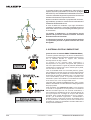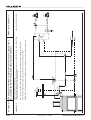
1
MONOBLOCCO
MBL TERMOPALEX 78•86
ISTRUZIONI USO E MANUTENZIONE
INSTRUCTIONS FOR USE AND MAINTENANCE
GEBRAUCHS- UND WARTUNGSANLEITUNG
La stufa a combustione ecologica che riscalda la tua casa
The eco-friendly combustion stove that heats your home
Der Heizofen mit der umweltfreundlichen Verbrennung, der Ihr ganzes Haus heizt
Le apparecchiature da riscaldamento (denominate in
seguito “caminetti”) PALAZZETTI LELIO S.P.A. (di seguito
PALAZZETTI) serie TERMOPALEX MONOBLOCCO sono
costruite e collaudate seguendo le prescrizioni di sicurezza
indicate nelle direttive europee di riferimento.
Questo manuale è indirizzato ai proprietari del caminetto,
agli installatori, operatori e manutentori dei caminetti serie
TERMOPALEX MONOBLOCCO.
In caso di dubbi sul contenuto e per ogni chiarimento
contattare il costruttore o il servizio di assistenza tecnica
autorizzato citando il numero del paragrafo dell'argomento
in discussione.
La stampa, la traduzione e la riproduzione anche
parziale del presente manuale s'intende vincolata
dall'autorizzazione Palazzetti.
Le informazioni tecniche, le rappresentazioni grafiche
e le specifiche presenti in questo manuale non sono
divulgabili.
IL SISTEMA A DOPPIA COMBUSTIONE
(presente solo sul modello EMBL TERMOPALEX 86)
La fiamma prodotta dalla legna che brucia correttamente in
una stufa emette la stessa quantità di anidride carbonica (CO2)
che si sarebbe liberata in seguito alla naturale
decomposizione del legno stesso.
La quantità di CO 2 prodotta dalla combustione o
decomposizione di una pianta corrisponde alla quantità di
CO2 che la pianta stessa è in grado di prelevare dall’ambiente
e trasformare in ossigeno per l’aria e carbonio per la pianta,
nel corso del suo ciclo di vita.
L’uso di combustibili fossili non rinnovabili (carbone, gasolio,
gas), a differenza di quanto avviene con la legna, libera nell’aria
enormi quantità di CO2 accumulate nel corso di milioni di anni,
aumentando la formazione dell’effetto serra. L’uso della legna
come combustibile, quindi, è in perfetto equilibrio con
l’ambiente in quanto viene utilizzato un combustibile rinnovabile
ed in armonia con il ciclo ecologico della natura.
Il principio della combustione pulita risponde in pieno a questi
obiettivi e la Palazzetti vi ha fatto riferimento nella progettazione
dei propri prodotti.
Cosa intendiamo per combustione pulita e come avviene?
Il controllo e la regolazione di aria primaria e l’immissione
dell’aria secondaria provoca una seconda combustione, o
post-combustione caratterizzata da una seconda fiamma più
viva e più limpida che si sviluppa al di sopra della fiamma
principale. Essa, grazie all’immissione di nuovo ossigeno,
brucia i gas incombusti migliorando sensibilmente il
rendimento termico e riducendo al minimo le emissioni nocive
di CO (monossido di carbonio) dovute alla combustione
incompleta. È questa una caratteristica esclusiva delle stufe e
di altri prodotti PALAZZETTI.
2/64
cod. 004770171 - 07/2009
TERMOPALEX MONOBLOCCO
IT
TERMOPALEX MONOBLOC series of heating
GB Palazzetti’s
appliances are made and tested following the safety
prescriptions for machines as laid down in the relative
European directives.
This manual is for ownersof the fireplace, and installers,
operators and maintenance engineers of the TERMOPALEX
MONOBLOC series of fireplaces.
If you have any doubts about the contents or need some
clarifications, do not hesitate to contact the manufacturer
or an authorised technical assistance centre, giving the
number of the paragraph in question.
The printing, translation and reproduction, even partial,
of this manual are bound by Palazzetti’s authorisation.
The technical information, graphs and specifications
in this manual are not to be disclosed.
Die Heizgeräte (nachstehend „Heizofen“ genannt) der Firma
PALAZZETTI LELIO S.P.A. (nachstehend PALAZZETTI
GENANNT) Mod. TERMOPALEX MONOBLOCCO werden
unter Einhaltung der von den diesbezüglichen europäische
Richtlinien vorgegebenen Sicherheitsbestimmungen
hergestellt und geprüft.
Dieses Handbuch richtet sich an den Eigentümer des
Heizofens Mod. TERMOPALEX MONOBLOCCO, sowie an
die Installateure, Bediener und das Wartungspersonal.
Im Zweifelsfalle bzw. für jede weitere Erklärung zum Handbuch
ist mit dem Hersteller oder der befugten
Kundendienststelle Kontakt aufzunehmen. Dabei bitte die
Absatznummer und das betreffende Argument angeben.
Der Druck, die Übersetzung und auch nur die teilweise
Vervielfältigung dieses Handbuchs unterstehen der
Genehmigung seitens der Fa. Palazzetti.
Die in diesem Handbuch enthaltenen technischen
Informationen, grafischen Darstellungen und
Spezifikationen dürfen nicht verbreitet werden.
DUAL COMBUSTION SYSTEM
DAS SYSTEM DER DOPPELTEN
VERBRENNUNG
(present only on the model EMBL TERMOPALEX 86)
In a fireplace, a correctly burning flame emits the same amount
of carbon dioxide (CO2) as would be emitted through the natural
decomposition of the same wood.
The quantity of CO2 produced by combustion or decomposition
of a tree corresponds to the quantity of CO2 that the tree itself is
capable of extracting from the environment and transforming
into oxygen for the air and carbon for itself during its lifetime.
Unlike wood, when fossil fuels are burned – which are not
renewable, like coal, diesel oil, gas - a huge amount of CO2
accumulated in the course of millions of years is emitted into
the atmosphere, increasing the green-house effect.
Consequently, the use of wood as fuel maintains the perfect
equilibrium of nature because it is a renewable fuel whose
burning is compatible with nature’s life cycle.
The principle of clean combustion is in perfect harmony with
these characteristics and Palazzetti always refers to it when
designing its products.
What exactly do we mean by clean combustion and how does
it come about?
By controlling the flow of primary air and by adding secondary
air, a second level of combustion, or post-combustion, takes
place. This is indicated by a second characteristically clearer
and stronger flame above the main flame. By adding new
oxygen, this flame consumes the unburned gasses,
remarkably improving heat production and reducing
t h e
harmful emission of CO (carbon monoxide) caused by
incomplete combustion.
This is a unique feature of the fireplaces and other PALAZZETTI
products.
TERMOPALEX MONOBLOCCO
(nur beim Modell EMBL TERMOPALEX 86 vorhanden)
Eine in einem Kaminofen korrekt brennende Flamme gibt die
gleiche Menge an Kohlendioxyd (C02) ab, die durch die
natürliche Zersetzung des Holzes selbst hätte erzeugt werden
können.
Die von der Verbrennung oder Zersetzung einer Pflanze
erzeugte C02-Menge entspricht der Menge, die eben diese
Pflanze während ihres Lebenszyklus aus der Atmosphäre
entnimmt und für die Luft in Sauerstoff bzw. für die Pflanze in
Kohlenstoff umwandeln kann.
Bei
der
Verwendung
von
nicht
erneuerbaren
Fossilbrennstoffen (Kohle, Dieselöl, Gas) werden im Gegenteil
zum Holz enorme Mengen an CO2, das sich im Laufe von
Millionen Jahren angesammelt hat, an die Atmosphäre
abgegeben, was zur Erhöhung des “Treibhauseffekts” beiträgt.
Demnach kann die Anwendung von Holz als Brennstoff als
umweltfreundlich angesehen werden, da ein erneuerbarer
Brennstoff verwendet wird, der sich harmonisch in den
natürlichen, ökologischen Zyklus einfügt.
Das von Palazzetti für Kaminöfen und Kamine angewandte
Prinzip der sauberen Verbrennung entspricht voll und ganz
diesen Zielsetzungen, woran man sich auch in der Planung
der Produkte hält.
Was versteht man unter sauberer Verbrennung und wie
funktioniert sie? Die Kontrolle der Primärluft und die Zufuhr
von Sekundärluft bewirken eine zweite Verbrennung bzw. eine
so genannte Nachverbrennung, bei der sich eine zweite
Flamme über der ersten entwickelt und lebendiger und auch
klarer brennt. Sie verbrennt durch die Zufuhr der ekundärluft
die unverbrannten Gase, wodurch die Heizleistung wesentlich
verbessert wird: die schädlichen, durch die unvollständige
Verbrennung bedingten CO-Emissionen (Kohlenmonoxyd)
werden auf ein Minimum reduziert. Es handelt sich hierbei um
ein exklusives Merkmal der Kaminöfen und anderen Produkte
der Fa. PALAZZETTI.
cod. 004770171 - 07/2009
3/64
D
IT
INDICE
5.5
COLLEGAMENTI IDRAULICI
5.5.1
Collegamento base
5.5.2
Collegamento base con bollitore
5.6
COLLEGAMENTI ELETTRICI
5.6.1
Installazione centralina digitale
6
MESSA IN SERVIZIO ED USO DEL
TERMOPALEX MONOBLOCCO
6.1
TIPO DI COMBUSTIBILE
6.2
VERIFICHE PRELIMINARI PRIMA
DELL’ACCENSIONE
RESPONSABILITÀ DEL COSTRUTTORE
6.3
CENTRALINA DIGITALE/ QUADRO DI CONTROLLO
1.10
CARATTERISTICHE DELL’UTILIZZATORE
6.4
1.11
ASSISTENZA TECNICA
PRIMA ACCENSIONE: INFORMAZIONI
PRELIMINARI
1.12
PARTI DI RICAMBIO
6.4.1
Accensione e uso del caminetto
1.13
CONSEGNA DEL CAMINETTO
6.5
COME USARE LA PORTINA
6.6
VALVOLA FUMI VDF
6.6.1
Funzionamento
7
MANUTENZIONE E PULIZIA
7.1
PRECAUZIONI DI SICUREZZA
7.2
PULIZIA DEL VETRO
7.3
PULIZIA DEL CASSETTO CENERE
7.4
MANUTENZIONE GENERALE
7.4.1
Ogni settimana
7.4.2
Pulizia stagionale - fine inverno
7.4.3
Pulizia canna fumaria
8
INFORMAZIONI PER LA DEMOLIZIONE E LO
SMALTIMENTO
9
SCHEMI IDRAULICI
10
CARATTERISTICHE TECNICHE
1
PREMESSA
1.1
SIMBOLOGIA
1.2
DESTINAZIONE D’USO
1.3
SCOPO E CONTENUTO DEL MANUALE
1.4
CONSERVAZIONE DEL MANUALE
1.5
AGGIORNAMENTO DEL MANUALE
1.6
GENERALITÀ
1.7
PRINCIPALI NORME RISPETTATE
E DA RISPETTARE
1.8
GARANZIA LEGALE
1.9
2
AVVERTENZE PER LA SICUREZZA
2.1
AVVERTENZE PER L’INSTALLATORE
2.2
AVVERTENZE PER L’UTILIZZATORE
2.3
AVVERTENZE PER IL MANUTENTORE
3
CARATTERISTICHE E DESCRIZIONE DEL
CAMINETTO
3.1
3.2
3.3
DESCRIZIONE
TARGHETTA DI IDENTIFICAZIONE
LA COMBUSTIONE
4
MOVIMENTAZIONE E TRASPORTO
5
INSTALLAZIONE
5.1
PRECAUZIONI PER LA SICUREZZA
5.2
CANNE FUMARIE E COMIGNOLI
5.3
MONTAGGIO DEL CAMINETTO
5.3.1
Predisposizione ambiente di installazione e
posizionamento a secco
5.3.2
Montaggio definitivo - Regolazione altezza
5.3.3
Impianto idraulico
5.3.4
Montaggio del rivestimento
5.3.5
Messa a terra
5.3.6
Collegamento alla canna fumaria
5.3.7.1
Controcappa e pannello di ispezione parti idrauliche
5.3.7.2
Montaggio pannello di ispezione e regolazione VDF
5.3.8
Smontaggio e montaggio deflettori
5.4
ACCESSORI
5.4.1
In dotazione
5.4.2
Opzionali
4/64
cod. 004770171 - 07/2009
TERMOPALEX MONOBLOCCO
CONTENTS
GB
1
GENERAL
1.1
SYMBOLS
1.2
USE OF THE FIREPLACE
1.3
PURPOSE AND CONTENTS OF THE MANUAL
1.4
KEEPING THE MANUAL
1.5
UPDATING THE MANUAL
1.6
GENERAL INFORMATION
1.7
MAIN REGULATIONS TO COMPLY WITH
1.8
5.5
PLUMBING
5.5.1
Basic connection
5.5.2
Basic connection with boiler
5.6
ELECTRICAL CONNECTIONS
5.6.1
Installing the digital control unit
6
COMMISSIONING AND USING
TERMOPALEX MONOBLOCCO
LEGAL GUARANTEE
6.1
TYPE OF FUEL
1.9
MANUFACTURER LIABILITIES
6.2
PRELIMINARY CHECKS PRIOR TO LIGHTING
1.10
USER CHARACTERISTICS
6.3
DIGITAL CONTROL UNIT / CONTROL PANEL
1.11
TECHNICAL ASSISTANCE
6.4
FIRST IGNITION: PRELIMINARY INFORMATION
1.12
SPARE PARTS
6.4.1
Lighting and using the fireplace
1.13
DELIVERY OF THE FIREPLACE
6.5
HOW TO USE THE DOOR
6.6
VDF SMOKE VALVE
2
SAFETY PRECAUTIONS
6.6.1
Operation
2.1
INSTRUCTIONS FOR THE INSTALLER
2.2
INSTRUCTIONS FOR THE USER
7
MAINTENANCE AND CLEANING
2.3
INSTRUCTIONS FOR THE MAINTENANCE
ENGINEER
7.1
SAFETY PRECAUTIONS
7.2
CLEANING THE GLASS
7.3
CLEANING THE ASH BOX
7.4
GENERAL MAINTENANCE
3
CHARACTERISTICS AND DESCRIPTION OF
THE FIREPLACE
3.1
DESCRIPTION
7.4.1
Every week
3.2
IDENTIFICATION TAG
7.4.2
Seasonal cleaning at the end of winter
3.3
COMBUSTION
7.4.3
Cleaning the flue
4
HANDLING AND TRANSPORT
8
INFORMATION FOR DEMOLITION AND
DISPOSAL
5
INSTALLATION
5.1
SAFETY PRECAUTIONS
9
PLUMBING DIAGRAMS
5.2
FLUES AND CHIMNEY TOPS
10
TECHNICAL FEATURES
5.3
ASSEMBLY OF THE FIREPLACE
5.3.1
Preparation of installation area and dry positioning
5.3.2
Final assembly - Height adjustment
5.3.3
Hydraulic system
5.3.4
Cladding assembly
5.3.5
Earthing
5.3.6
Connection to flue pipe
5.3.7.1
Counter-hood and inspection panel hydraulic
system
5.3.7.2
Inspection panel installation and VDF adjustment
5.3.8
Removing and mounting the diaphragms
5.4
ACCESSORIES
5.4.1
Equipped
5.4.2
Optionals
TERMOPALEX MONOBLOCCO
cod. 004770171 - 07/2009
THE
5/64
D
NHALTSVERZEICHNIS
1
EINLEITUNG
5.5
WASSERANSCHLÜSSE
1.1
SYMBOLE
5.5.1
Anschluss des Unterteils
1.2
ANWENDUNGSZWECK
5.5.2
Anschluss des Unterteils mit Boiler
1.3
ZWECK UND INHALT DES HANDBUCHS
5.6
STROMANSCHLÜSSE
1.4
AUFBEWAHRUNG DES HANDBUCHS
5.6.1
Installation der Digitale Steuereinheit
1.5
ERGÄNZUNG DES HANDBUCHS
1.6
ALLGEMEINE INFORMATIONEN
6
INBETRIEBNAHME UND GEBRAUCH DES
TERMOPALEX MONOBLOCCO
1.7
GRUNDLEGENDE EINGEHALTENE UND
EINZUHALTENDE
6.1
BRENNSTOFFE
1.8
GESETZLICHE GARANTIE
6.2
VOR DER ZÜNDUNG DURCHZUFÜHRENDE
PRÜFUNGEN
1.9
HAFTBARKEIT DES HERSTELLERS
6.3
DIGITALE STEUEREINHEIT/ BEDIENBLENDE
1.10
EIGENSCHAFTEN DES BENUTZERS
6.4
ERSTE ZÜNDUNG: VORABHINWEISE
1.11
TECHNISCHER KUNDENDIENST
6.4.1
Zündung und Gebrauch des Heizkamins
1.12
ERSATZTEILE
6.5
HANDHABUNG DER TÜ
1.13
LIEFERUNG DES HEIZOFENS
6.6
VDF-RAUCHVENTIL
2
VORBEUGENDE SICHERHEITSMASSNAHMEN
6.6.1
Betrieb
2.1
HINWEISE FÜR DEN INSTALLATEUR
7
INSTANDHALTUNG UND REINIGUNG
2.2
HINWEISE FÜR DEN BENUTZER
7.1
VORBEUGENDE SICHERHEITSMASSNAHMEN
2.3
HINWEISE FÜR DAS WARTUNGSPERSONAL
7.2
REINIGUNG DES GLASES
3
MERKMALE UND GERÄTEBESCHREIBUNG
7.3
REINIGUNG DES ASCHENKASTENS
3.1
BESCHREIBUNG
7.4
ALLGEMEINE WARTUNG
3.2
TYPESCHILD
7.4.1
Wöchentlich
3.3
DIE VERBRENNUNG
7.4.2
Reinigung bei Wintersaisonende
7.4.3
Reinigung des Rauchfangs
8
INFORMATIONEN FÜR DEN ABRISS UND DIE
ENTSORGUNG
9
HYDRAULIKPLÄNE
10
TECHNISCHE EIGENSCHAFTEN
4
HANDLING UND TRANSPORT
5
INSTALLATION
5.1
VORBEUGENDE SICHERHEITSMASSNAHMEN
5.2
RAUCHFÄNGE UND
5.3
MONTAGE DES HEIZKAMINS
5.3.1
Vorbereitung des Installationsortes
provisorische Aufstellung
5.3.2
Endgültige Montage - Höheneinstellung
5.3.3
Hydraulische Anlage
5.3.4
Montage der Verkleidung
5.3.5
Erdung
5.3.6
Anschluss an den Rauchfang
5.3.7.1
Gegenhaube und Inspektionspaneel
5.3.7.2
Montage des Inspektionspaneels und VDFEinstellung
5.3.8
Abnahme und Montage der Rauchleitbleche
5.4
ZUBEHÖR
5.4.1
Gehört zum Lieferumfang
5.4.2
Zusätzliches Zubehör
6/64
SCHORNSTEINE
und
cod. 004770171 - 07/2009
TERMOPALEX MONOBLOCCO
TERMOPALEX MONOBLOCCO
cod. 004770171 - 07/2009
7/64
Gentile cliente,
IT
desideriamo innanzitutto ringraziarLa per la preferenza
che ha voluto accordarci acquistando il nostro prodotto
e ci congratuliamo con Lei per la scelta.
Per consentirLe di utilizzare al meglio il Suo nuovo
caminetto TERMOPALEX MONOBLOCCO, la invitiamo
a seguire attentamente quanto descritto nel presente
manuale.
1
PREMESSA
Non operare se non si sono ben comprese tutte le
notizie riportate nel manuale; in caso di dubbi
richiedere sempre l’intervento di personale
specializzato PALAZZETTI.
Palazzetti si riserva il diritto di modificare specifiche
e caratteristiche tecniche e/o funzionali del prodotto
in qualsiasi momento senza darne preavviso.
1.1
SIMBOLOGIA
Nel presente manuale i punti di rilevante importanza
sono evidenziati dalla seguente simbologia:
INDICAZIONE: Indicazioni concernenti il corretto utilizzo
della stufa e le responsabilità dei preposti.
ATTENZIONE: Punto nel quale viene espressa una
nota di particolare rilevanza.
!
1.2
PERICOLO: Viene espressa un’importante nota di
comportamento per la prevenzione di infortuni o danni
materiali.
DESTINAZIONE D’USO
L’apparecchiatura
PALAZZETTI
modello
TERMOPALEX MONOBLOCCO è il nuovo caminetto
per il riscaldamento, realizzato da una struttura
completamente metallica, con focolare chiuso da un
vetro - ceramico.
Il caminetto funziona in maniera ottimale con la porta
del focolare chiusa.
Il caminetto è caratterizzato da un doppio sistema di
combustione PRIMARIA e SECONDARIA con effetti
positivi sia sul rendimento che sulla emissione di
“fumi più puliti”.
La destinazione d’uso sopra riportata e le
configurazioni previste dell’apparecchiatura sono le
uniche ammesse dal Costruttore: non utilizzare il
prodotto in disaccordo con le indicazioni fornite.
!
1.3
La destinazione d’uso indicata è valida solo per
apparecchiature in piena efficienza strutturale,
meccanica ed impiantistica. Il caminetto PALAZZETTI
è un apparecchio solo da interno.
SCOPO E CONTENUTO DEL MANUALE
SCOPO
Lo scopo del manuale è quello di consentire
all’utilizzatore di prendere quei provvedimenti e
8/64
cod. 004770171 - 07/2009
TERMOPALEX MONOBLOCCO
GB
Dear customer,
Sehr geehrter Kunde,
We would first of all like to thank you for having chosen
one of our products and congratulate you on your
choice.
Zu allererst möchten wir Ihnen für den uns gewährten
Vorzug danken und Ihnen zur Wahl gratulieren.
Damit Sie Ihren neuen Kaminofen TERMOPALEX
MONOBLOCCO so gut wie möglich benutzen können,
bitten wir Sie, die in diesem Handbuch enthaltenen
Angaben genau zu befolgen.
So you will get the best out of your new TERMOPALEX
MONOBLOC fireplce, please follow the advice and
instructions given in this manual.
1
1
GENERAL
Keinesfalls vorgehen, wenn Sie nicht alle Hinweise
des Handbuchs verstanden haben; im Zweifelsfall
immer den Eingriff von Fachpersonal der Fa.
PALAZZETTI anfordern.
Do not start using the stove until you have read and
understood the contents of this manual. If you have
any doubts at any time do not hesitate to call the
PALAZZETTI specialized personnel who are there to
help you.
Die Firma Palazzetti behält sich das Recht vor,
Spezifikationen und technische bzw. funktionelle
Eigenschaften des Geräts jederzeit und ohne
Vorbescheid zu ändern.
Palazzetti reserves the right to modify the technical
and/or functional specifications and features at any
time without prior notice.
1.1
!
1.2
1.1
SYMBOLS
In diesem Handbuch sind die wichtigen Punkte durch
folgende Symbole gekennzeichnet:
INDICATION:Indications concerning the correct use of
the stove and the responsibilities of those using it.
HINWEIS: Hinweise zum korrekten Gebrauch des
Kaminofens unter Verantwortung des Bedieners.
ATTENTION: A particularly important note is written
here.
ACHTUNG: Damit werden besonders wichtige
Anmerkungen gekennzeichnet.
DANGER: Here you are warned of the possibility of
bodily harm or material damages.
!
GEFAHR: Hierbei handelt es sich um wichtige
Verhaltenshinweise zur Vorbeugung von Verletzungen
oder Materialschäden.
USE OF THE STOVE
1.2
Der Kaminofen funktioniert bei geschlossener
Feuerraumtür optimal.
This fireplace features the dual PRIMARY and
SECONDARY combustion system with positive effects
both on efficiency and on the emission of “cleaner
smoke”.
Der Kaminofen zeichnet sich durch ein doppeltes
Verbrennungssystem
mit
PRIMÄRUND
SEKUNDÄRVERBRENNUNG aus, was sich nicht nur
auf die Heizleistung positiv auswirkt, sondern auch
„reinere Abgase“ bewirkt.
Use of the stove, as described above, and its
configurations are only those allowed by the
manufacturer: do not use the product in
disagreement with the indications provided.
Der oben genannte Anwendungszweck bzw. die für
das Gerät vorgesehenen Konfigurationen sind die
einzigen vom Hersteller zugelassenen: das Produkt
nicht gegen die gelieferten Anweisungen
verwenden.
The indicated use of the fireplace is applicable only
for fireplaces in full structural, mechanical and
engineering efficiency. The PALAZZETTI fireplace is
for indoor use only.
PURPOSE AND CONTENTS OF THE MANUAL
PURPOSE
ANWENDUNGSZWECK
Das neue Kaminofenmodell TERMOPALEX
MONOBLOCCO von PALAZZETTI ist der neue
Kaminofen mit einer ganz aus Metall bestehenden
Struktur die Feuerstelle und ist mit Keramikglas
geschlossen.
The fireplace operates at its best when the firebox
door is shut.
1.3
SYMBOLE
The important points in this manual are highlighted
with the following symbols:
The PALAZZETTI TERMOPALEX MONOBLOC model
stove is the new fireplace heater, consisting in a
structure made completely of metallic material, with
the firebox enclosed by ceramic glass.
!
EINLEITUNG
!
Der angegebene Anwendungszweck gilt nur für Geräte
mit einwandfreier Struktur, Mechanik und Anlage. Der
Kaminofen von PALAZZETTI ist nur für Innenräume
geplant.
The purpose of the manual is to allow the user to take
the necessary precautions and to have all the human
and material means required for its correct, safe and
TERMOPALEX MONOBLOCCO
cod. 004770171 - 07/2009
9/64
D
predisporre tutti i mezzi umani e materiali necessari
per un suo uso corretto, sicuro e duraturo.
CONTENUTO
Questo manuale contiene tutte le informazioni
necessarie per l’installazione, l’impiego e la
manutenzione del caminetto TERMOPALEX
MONOBLOCCO.
La scrupolosa osservanza di quanto in esso descritto
garantisce un elevato grado di sicurezza e produttività
del caminetto.
1.4
CONSERVAZIONE DEL MANUALE
CONSERVAZIONE E CONSULTAZIONE
Il manuale deve essere conservato con cura e deve
essere sempre disponibile per la consultazione, sia
da parte dell’utilizzatore che degli addetti al montaggio
ed alla manutenzione.
Il manuale Istruzione Uso e Manutenzione è parte
integrante del prodotto.
DETERIORAMENTO O SMARRIMENTO
In caso di necessità fare richiesta di un’ulteriore copia
a PALAZZETTI.
CESSIONE DEL CAMINETTO
In caso di cessione del caminetto l'utente è obbligato
a consegnare al nuovo acquirente anche il presente
manuale.
1.5
AGGIORNAMENTO DEL MANUALE
Il presente manuale rispecchia lo stato dell'arte al
momento dell’immissione sul mercato del prodotto.
Le apparecchiature già presenti sul mercato, con la
relativa documentazione tecnica, non verranno
considerate da PALAZZETTI carenti o inadeguate a
seguito di eventuali modifiche, adeguamenti o
applicazione di nuove tecnologie su apparecchi di
nuova commercializzazione.
1.6
GENERALITÀ
INFORMAZIONI
In caso di scambio di informazioni con il Costruttore
del caminetto fare riferimento al codice a barre presente
nelle etichette che seguono il presente libretto ed ai
dati identificativi indicati alla pagina "INFORMAZIONI
GENERALI" alla fine del presente manuale.
RESPONSABILITÀ
Con la consegna del presente manuale PALAZZETTI
declina ogni responsabilità, sia civile che penale, per
incidenti derivati dalla non osservanza parziale o totale
delle specifiche in esso contenute.
PALAZZETTI declina, altresì, ogni responsabilità
derivante da uso improprio del caminetto od uso non
corretto da parte dell’utilizzatore, da modifiche e/o
riparazioni non autorizzate, da utilizzo di ricambi non
originali o non specifici per questo modello di
TERMOPALEX MONOBLOCCO.
MANUTENZIONE STRAORDINARIA
Le operazioni di manutenzione straordinaria devono
essere eseguite da personale qualificato ed abilitato
ad intervenire sul modello di stufa a cui fa riferimento
il presente manuale.
10/64
cod. 004770171 - 07/2009
TERMOPALEX MONOBLOCCO
IT
lasting use.
GB
1.3
ZWECK UND INHALT DES HANDBUCHS
D
CONTENTS
ZWECK
This manual contains all the information necessary
for installation, use and maintenance of the
TERMOPALEX MONOBLOC fireplace.
Zweck des Handbuchs ist es, dem Bediener die
nötigen Grundlagen zu liefern, um für einen korrekten,
sicheren und dauerhaften Gebrauch des Kaminofens
die geeigneten Maßnahmen zu treffen bzw. alle
menschlichen und materiellen Mittel zur Verfügung zu
stellen.
By complying scrupulously with the contents of this
manual you will ensure a high degree of safety and
productivity of the fireplace.
INHALT
1.4
KEEPING AND CONSULTING THE MANUAL
Dieses Handbuch enthält alle für die Installation, den
Gebrauch und die Wartung des Kaminofens
TERMOPALEX MONOBLOCCO nötigen Informationen.
The manual must be kept in a safe, dry place and be
available at all times for consultation by the user and
by those who see to its installation and maintenance.
Die gewissenhafte Beachtung aller Anweisungen
gewährleistet einen hohen Sicherheits- und
Produktivitätsgrad des Kaminofens.
KEEPING THE MANUAL
The instructions for use and maintenance manual
is an integral part of the product.
DETERIORATION OR LOSS
1.4
AUFBEWAHRUNG UND NACHSCHLAGEN
If needed, ask Palazzetti for another copy of the manual.
Das Handbuch muss sorgfältig aufbewahrt werden
und sowohl für den Benutzer, als auch für das Montageund Wartungspersonal immer zum Nachschlagen
verfügbar sein.
SELLING THE FIREPLACE
If the fireplace is sold the user must give the manual
to the new owner as well.
1.5
MANUAL UPDATE
Das
Handbuch
Wartungsanleitung”
Produktebestandteil.
This manual reflects the state-of-the-art at the time
the product was put on the market.
VERSCHLEISS ODER VERLUST
GENERAL INFORMATION
VERKAUF DES KAMINOFENS
Beim eventuellen Verkauf des Kaminofens muss dem
neuen Käufer auch das Handbuch ausgehändigt
werden.
1.5
INFORMATION
Die bereits auf dem Markt befindlichen Geräte und deren
technische Dokumentation werden von der Fa. PALAZZETTI
nach eventuellen Änderungen, Anpassungen oder
Anwendung neuer Technologien für neue Geräte nicht als
überholt bzw. ungeeignet angesehen.
LIABILITIES
PALAZZETTI also declines all liabilities resulting from
an improper use of the fireplace, incorrect use by the
user or resulting from unauthorised alterations and/
or repairs, or the use of spare parts that are either not
genuine or not specific for this particular model.
EXTRAORDINARY MAINTENANCE
Extraordinary maintenance must be carried out by
personnel qualified to work on the fireplace model to
which this manual refers.
RESPONSIBILITY FOR INSTALLATION
It is not PALAZZETTI’s responsibility to carry out the
works needed to install the fireplace. Such works are
entirely up to the installer who is requested to check
TERMOPALEX MONOBLOCCO
ERWEITERUNG DES HANDBUCHS
Dieses Handbuch entspricht dem technischen Stand
zum Zeitpunkt der Erstvermarktung des Produkts.
If there is an exchange of information with the stove
manufacturer, please quote the serial number and
identification data which you will find on the “GENERAL
INFORMATION” page at the end of this manual.
Upon delivery of this manual PALAZZETTI declines all
liabilities, both civil and penal, for any accidents that
may derive from the total or partial failure to comply
with the specifications contained in it.
“Gebrauchsund
ist
integrierender
Falls nötig, bei der Fa. PALAZZETTI eine Ersatzkopie
anfordern
The appliances already on the market, together with
their technical documentation, will not be considered
by PALAZZETTI as wanting or inadequate simply
because changes or adjustments have been made
or new technologies have been applied to the next
generation of appliances.
1.6
AUFBEWAHRUNG DES HANDBUCHS
1.6
ALLGEMEINES
INFORMATIONEN
Bei Nachfragen beim Kaminofenhersteller immer die
Seriennummer und die Identifikationsdaten angeben.
Diese Daten sind der Seite „ALLGEMEINE
INFORMATIONEN“ am Ende dieses Handbuchs zu
entnehmen.
HAFTBARKEIT
Mit der Übergabe dieses Handbuchs weist die Fa.
PALAZZETTI jede sowohl zivil- als auch strafrechtliche
Haftbarkeit für Unfälle zurück, die zwecks mangelnder
oder kompletter Nichtbeachtung der darin enthaltenen
Spezifikationen entstehen.
Die Firma PALAZZETTI weist des Weiteren jede
cod. 004770171 - 07/2009
11/64
RESPONSABILITÀ DELLE OPERE DI INSTALLAZIONE
La responsabilità delle opere eseguite per
l'installazione del caminetto non può essere
considerata a carico della PALAZZETTI, essa è, e
rimane, a carico dell’installatore, al quale è
demandata l’esecuzione delle verifiche relative alla
canna fumaria e della presa d’aria ed alla correttezza
delle soluzioni di installazione proposte. Devono
essere rispettate tutte le norme previste dalla
legislazione locale, nazionale ed europea vigente nello
stato dove la stessa è installata.
USO
L'uso del prodotto è subordinato, oltre che alle
prescrizioni contenute nel presente manuale, anche
al rispetto di tutte le norme di sicurezza previste dalla
legislazione specifica vigente nello stato dove la
stessa è installata.
1.7
PRINCIPALI NORME RISPETTATE E DA
RISPETTARE
A) Direttiva 2006/95/CE: “Materiale elettrico destinato
ad essere adoperato entro taluni limiti di tensione “.
B) Direttiva 2004/108/CE: “Ravvicinamento delle
legislazioni degli Stati membri relative alla
compatibilità elettromagnetica”.
C) Direttiva 89/391/CEE: “Attuazione delle misure volte
a promuovere il miglioramento della sicurezza e della
salute dei lavoratori durante il lavoro”.
D)Direttiva
89/106/CEE:
“Concernente
il
riavvicinamento delle disposizioni legislative,
regolamentari ed amministrative degli stati membri
concernenti i prodotti da costruzione”.
E)Direttiva 85/374/CEE: “Concernente il riavvicinamento
delle disposizioni legislative, regolamentari ed
amministrativee degli stati membri in materia di
responsabilità per danno da prodotti difettosi”.
F)Direttiva
1999/5/CE:
“Riguardante
le
apparecchiature radio e le apparecchiature terminali
di telecomunicazione e il reciproco riconoscimento
della loro conformità”.
1.8 GARANZIA LEGALE
L'utente per poter usufruire della garanzia legale, di
cui alla Direttiva CEE 1999/44/CE deve osservare
scrupolosamente le prescrizioni indicate nel presente
manuale, ed in particolare:
• operare sempre nei limiti d'impiego del caminetto;
• effettuare sempre una costante e diligente
manutenzione;
• autorizzare all’uso della stufa persone di provata
capacità, attitudine ed adeguatamente addestrate allo
scopo.
L'innosservanza delle prescrizioni contenute in questo
manuale implicherà l’immediata decadenza della
garanzia.
1.9
RESPONSABILITÀ DEL COSTRUTTORE
Il Costruttore declina ogni responsabilità civile e
penale, diretta o indiretta, dovuta a:
12/64
cod. 004770171 - 07/2009
TERMOPALEX MONOBLOCCO
IT
the flue and air intake and to check if the installation
solutions proposed are feasible. All applicable
standards and local, national and European
legislation in force in the country where the fireplace
is installed must be respected.
GB
Verantwortung für Unfälle zurück, die aus einem
unzweckmäßigen
oder
nicht
korrekten
Gerätegebrauch seitens des Benutzers, aus
unbefugten Änderungen bzw.
Reparaturen, dem Einsatz von Nicht-Originalersatzteilen
oder nicht spezifisch für dieses Modell TERMOPALEX
MONOBLOCCO geeignet, entstehen.
USE
Use of the stove is subject to compliance with all the
safety standards established by the relevant laws in
force in the place of installationbesides the
prescriptions contained in this manual.
1.7
AUSSERORDENTLICHE WARTUNG
Die außerordentlichen Wartungsarbeiten müssen von
Fachpersonal, das für den Eingriff am, in diesem
Handbuch beschriebenen Kaminofenmodell befugt
ist, ausgeführt werden.
MAIN REGULATIONS TO COMPLY WITH
HAFTUNG FÜR DIE INSTALLATION
A) Directive 2006/95/CE: “Electrical material to be
used within certain voltage limits”.
Die Haftung für die Installation des Kaminofens geht
keinesfalls zu Lasten der Fa. PALAZZETTI. Sie geht zu
Lasten des Installateurs, dem die Ausführung der
Kontrollen des Rauchfangs und der Lüftungsöffnung
bzw. der Korrektheit der
Installationsvorschläge
übertragen wird. Es sind alle Vorschriften der örtlichen,
nationalen und europäischen Gesetzgebung zu
beachten, die im jeweiligen Aufstellungsland gültig sind.
B) Directives 2004/108/CE: “Standardization of the
legislation of member states concerning
electromagnetic compatibility”.
C) Directive 89/391/CEE: “Implementation of
measures to promote improvement of the safety and
health of workers during their working hours.”.
D) Directive 89/106/CEE: “Concerning the
standardization of legislative, regulating and
administrative guidelines of the member states on
the subject of construction products”.
E) Directive 85/374/CEE: “Concerning the
standardization of legislative, regulating and
administrative guidelines of the state members on the
subject of liability for damages due to faulty products”.
GEBRAUCH
Der Gebrauch des Geräts untersteht nicht nur den
präzisen Anweisungen dieses Handbuchs, sondern
auch der Beachtung aller im Installationsland
vorgesehenen Sicherheitsnormen.
1.7
F)Directive 1999/5/CE: “Regarding radio equipment
and telecommunication terminal equipment and the
reciprocal recognition of their compliance”.
1.8
A) Richtlinie 2006/95/CE: “Elektrisches Material, das
innerhalb bestimmter Spannungsgrenzen zu
verwenden ist “.
B) Richtlinie 2004/108/CE: “Angleichung der
Gesetzgebung der Mitgliedsstaaten hinsichtlich der
elektromagnetischen Verträglichkeit”.
C) Richtlinie 89/391/EWG: “Durchführung von
Maßnahmen zur Verbesserung der Sicherheit und des
Gesundheitsschutzes der Arbeitnehmer bei der Arbeit”.
D) Richtlinie 89/106/EWG: “Angleichung der Gesetzes-,
Regelund
Verwaltungsvorschriften
der
Mitgliedstaaten
hinsichtlich der Bauprodukte”.
E) Richtlinie 85/374/EWG: “Angleichung der
Gesetzes-, Regel- und Verwaltungsvorschriften der
Mitgliedstaaten hinsichtlich der Haftung für Schäden
durch fehlerhafte Produkte”.
LEGAL GUARANTEE
The user may only make use of the legal guarantee,
as under the EEC directive 1999/44/CE, if he has
scrupulously complied with the regulations indicated
in this manual, and more specifically:
• To work always within the fireplace’s range of use
• Maintenance must be constant and accurate;
• Only allow people who are capable and who have
been suitably trained to use the fireplace.
Failure to comply with the regulations contained in
this manual will invalidate the guarantee immediately.
1.9
F) Richtlinie 1999/5/CE: “Bezüglich Funkgeräten und
Telekommunikationsendeinrichtungen ind der
gegenseitigen Anerkennung ihrer Konformität ”.
MANUFACTURER’S LIABILITY
The manufacturer declines all civil and penal
liabilities, direct or indirect, due to:
• An installation that fails to comply with the laws in
force in the country and with the safety rules and
regulations;
• Failure to comply with the instructions given in the
manual;
• An installation by unqualified and untrained
personnel;
• Use that fails to conform to the safety directives;
• Alterations and repairs on the appliance not
authorised by the manufacturer;
TERMOPALEX MONOBLOCCO
GRUNDLEGENDE EINGEHALTENE UND
EINZUHALTENDE
1.8
GEWÄHRLEISTUNG
Damit der Benutzer die gesetzliche Garantie laut
Richtlinie 1999/44/EG beanspruchen kann, hat er die
Anweisungen dieses Handbuchs gewissenhaft zu
befolgen und insbesondere:
• immer innerhalb der Einsatzgrenzen des
Kaminofens vorzugehen;
• die Wartung regelmäßig und sorgfältig auszuführen;
• nur Personen mit den geeigneten Kapazitäten und
Befähigungen bzw. zu diesem Zweck geschulte
Personen mit der Kaminofenbedienung zu
beauftragen.
cod. 004770171 - 07/2009
13/64
D
• installazione non conforme alle normative vigenti nel
paese ed alle direttive di sicurezza;
• inosservanza delle istruzioni contenute nel manuale;
• installazione da parte di personale non qualificato e
non addestrato;
• uso non conforme alle direttive di sicurezza;
• modifiche e riparazioni non autorizzate dal Costruttore
effettuate sul prodotto;
• utilizzo di ricambi non originali o non specifici per il
modello di stufa;
• carenza di manutenzione;
• eventi eccezionali.
1.10
CARATTERISTICHE DELL’UTILIZZATORE
L'utilizzatore del caminetto deve essere una persona
adulta e responsabile provvista delle conoscenze
tecniche necessarie per la manutenzione ordinaria
dei componenti del caminetto.
1.11
ASSISTENZA TECNICA
Palazzetti è in grado di risolvere qualunque problema
tecnico riguardante l’impiego e la manutenzione
nell'intero ciclo di vita del prodotto.
La sede centrale è a vostra disposizione per indirizzarvi
al più vicino centro di assistenza autorizzato.
1.12
PARTI DI RICAMBIO
Impiegare esclusivamente parti di ricambio originali.
Non attendere che i componenti siano logorati dall’uso
prima di procedere alla loro sostituzione.
Sostituire un componente usurato prima della rottura
favorisce la prevenzione degli infortuni derivanti da
incidenti causati proprio dalla rottura improvvisa dei
componenti, che potrebbero provocare gravi danni a
persone e cose.
Eseguire i controlli periodici di manutenzione come
indicato nel capitolo “MANUTENZIONE E PULIZIA”.
1.13
CONSEGNA DEL CAMINETTO
Il caminetto viene consegnato perfettamente imballato
e fissato ad una pedana in legno che ne permette la
movimentazione mediante carrelli elevatori e/o altri
mezzi.
All’interno del caminetto viene allegato un Kit in
scatola di cartone contenente:
• 1 valvola di sicurezza DN ½”.
14/64
cod. 004770171 - 07/2009
TERMOPALEX MONOBLOCCO
IT
• Use of spare parts that are either not genuine or
specific for this particular model of fireplace;
GB
Das fehlende Einhalten der Beschreibungen dieses
Handbuchs führt zum unverzüglichen Garantieverfall.
• Lack of maintenance;
• Exceptional events.
1.10
1.9
Der Hersteller lehnt in folgenden Fällen jede direkte
oder indirekte zivil- und strafrechtliche Haftung ab:
• Nicht konform mit den im Aufstellungsland gültigen
Bestimmungen und den Sicherheitsrichtlinien
erfolgte Installation;
• Fehlendes Einhalten der im Handbuch enthaltenen
Anweisungen;
• Installation durch nicht qualifiziertes bzw. nicht
geschultes Personal;
• Nicht mit den Sicherheitsrichtlinien konformer Gebrauch;
• Nicht vom Hersteller befugte Änderungen und
Reparaturen am Gerät;
• Einsatz von Nicht-Originalersatzteilen oder nicht spezifisch
für dieses Kaminofenmodell geeigneten Ersatzteilen;
• Mangelnde Wartung;
• Außerordentliche Vorkommnisse.
USER CHARACTERISTICS
The person who uses the fireplace must be an adult
and responsible, with all the necessary technical
know-how to carry out routine maintenance of the
mechanical and electrical components of the fireplace.
1.11
TECHNICAL ASSISTANCE
PALAZZETTI is able to solve any technical problem
concerning the use and maintenance of the product’s
whole life cycle.
The main office will help you find the nearest
authorised assistance centre.
1.12
SPARE PARTS
1.10
Use genuine spare parts only.
Changing a worn component before it breaks makes
it easier to prevent accidents that could otherwise lead
to serious injury to people or damage to things.
1.13
1.11
TECHNISCHER KUNDENDIENST
Die Fa. PALAZZETTI ist in der Lage, jedes technische
Problem bezüglich der Benutzung oder der Wartung
während der gesamten Lebensdauer des Produkts
zu lösen.
DELIVERY OF THE STOVE
Unser Firmensitz teilt Ihnen gerne mit, wo sich die
nächstgelegene befugte Kundendienststelle befindet.
The fireplace is delivered perfectly packed and
attached to a wooden platform which allows it to be
handled by forklifts and/or other means.
A cardboard box in the fireplace contains a kit with the
following:
EIGENSCHAFTEN DES BENUTZERS
Der Benutzer des Kaminofens muss ein
verantwortungsbewusster Erwachsener mit den
nötigen technischen
Kenntnissen für die regelmäßige Instandhaltung der
Kaminofen-Bestandteile sein.
Do not wait until the components are worn from use
before changing them.
Carry out the routine maintenance checks as
explained in the “MAINTENANCE AND CLEANING”
chapter.
HAFTBARKEIT DES HERSTELLERS
1.12
ERSATZTEILE
Ausschließlich Original-Ersatzteile verwenden.
• 1 safety valve DN ½”.
Vor dem Austausch gewisser Bestandteile nicht erst
abwarten, bis sie komplett abgenutzt sind.
Wird ein verschlissener Bestandteil vor seinem
kompletten Kaputtgehen ersetzt, können Unfälle, die
eben auf das plötzliche Kaputtgehen von Teilen
zurückzuführen sind und schwere Personen- und
Sachschäden verursachen könnten, vermieden werden.
Die regelmäßigen Kontrollen zur Instandhaltung laut
Kapitel „WARTUNG UND REINIGUNG“ durchführen.
1.13
LIEFERUNG DES KAMINOFENS
Der Heizkamin wird einwandfrei verpackt und auf einer
Holzpalette befestigt geliefert, dadurch wird das
Handling mit einem Gabelstapler und/oder anderen
Hilfsmitteln möglich.
Im Innern des Heizkamins befindet sich ein Karton
mit einem Bausatz, der folgendes enthält:
• sicherheitsventil DN ½”.
TERMOPALEX MONOBLOCCO
cod. 004770171 - 07/2009
15/64
D
2
2.1
AVVERTENZE PER LA SICUREZZA
AVVERTENZE PER L’INSTALLATORE
!
• Il caminetto deve essere installato da personale
qualificato,
per la parte fumistica,
per i collegamenti idraulici,
per eventuali parti elettriche,
per la regolazione e l’avvio dell’impianto.
• Operare in conformità ai regolamenti locali, nazionali
ed europei.
• Osservare le prescrizioni indicate nel presente
manuale.
• Verificare che le predisposizioni della canna fumaria
e della presa d’aria siano conformi al tipo di
installazione.
• Non creare restringimento o strozzature nel circuito
idraulico.
• Non effettuare collegamenti elettrici volanti con cavi
provvisori o non isolati.
• Verificare che la messa a terra dell’impianto elettrico
sia efficiente.
• Usare sempre i dispositivi di sicurezza individuale e
gli altri mezzi di protezione previsti per legge.
2.2
AVVERTENZE PER L’UTILIZZATORE
!
• Predisporre il luogo d’installazione della stufa
secondo i regolamenti locali, nazionali ed europei.
• Il caminetto, essendo un’apparecchiatura da
riscaldamento, presenta delle superfici esterne
particolarmente calde.
Per questo motivo si raccomanda la massima cautela
durante il funzionamento in particolare:
• non toccare e non avvicinarsi al vetro della porta,
potrebbe causare ustioni;
• non toccare lo scarico dei fumi;
• non eseguire pulizie di qualunque tipo;
• fare attenzione che i bambini non si avvicinino.
• Osservare le prescrizioni indicate nel presente
manuale.
• Rispettare le istruzioni e gli avvertimenti evidenziati
dalle targhette esposte sul caminetto.
• Le targhette sono dispositivi antinfortunistici , pertanto
devono essere sempre perfettamente leggibili.
Qualora risultassero danneggiate ed illeggibili è
obbligatorio sostituirle, richiedendone il ricambio
originale al costruttore.
• Utilizzare solo il combustibile conforme alle
indicazioni riportate sul capitolo relativo alle
caratteristiche del combustibile stesso.
• Seguire scrupolosamente il programma di
manutenzione ordinaria e straordinaria.
• Non impiegare il caminetto senza prima avere
16/64
cod. 004770171 - 07/2009
TERMOPALEX MONOBLOCCO
IT
GB
2
2.1
SAFETY PRECUATIONS
2
VORBEUGENDE
SICHERHEITSMASSNAHMEN
2.1
HINWEISE FÜR DEN INSTALLATEUR
INSTRUCTIONS FOR THE INSTALLER
!
• The fireplace must be installed by qualified
personnel,
!
for the smoke part,
• Der Heizkamin muss von Fachpersonal installiert
werden,
for the hydraulic connections,
für den Rauchabschnitt,
for any electrical parts,
für die hydraulischen Anschlüsse,
for adjustment and start-up of the system.
für eventuelle elektrische Teile,
• Work in compliance with the national and European
rules and regulations.
D
für die Einstellung und die Inbetriebnahme der Anlage.
• In Konformität dass die Vorbereitungen für die
Kaminofeninstallation den örtlichen, nationalen und
europäischen Normen entsprechen.
• Comply with the indications given in this manual.
• Check that the flue and air intake are suitable for the
type of installation opted for.
• Die aufgeführten Vorschriften in diesem Handbuchs
beachten.
• Do not create narrows or chokes in the plumbing
circuit.
• Sicherstellen, dass sich der Rauchfang und die
Lüftungsöffnung für die vorgesehene Installation eignen.
• The electrical connection must not be done using
temporary or non-insulated leads.
• Make sure the electrical systems earthing is efficient.
• Keine Querschnittverkleinerungen oder Drosselungen
am Wasserkreislauf erzeugen.
•Always use the individual safety devices and the other
protection gear as established by law.
•Keine losen Stromanschlüsse mit provisorischen
oder nicht isolierten Kabeln durchführen.
•Sicherstellen, dass die Erdung der Stromleitung
wirksam ist.
2.2
!
INSTRUCTIONS FOR THE USER
• Prepare the place of installation of the fireplace in
accordance with the local, national and European rules
and regulations.
• Immer die persönlichen Sicherheitsausrüstungen
und die gesetzlich vorgesehenen Schutzmittel
verwenden.
2.2
HINWEISE FÜR DEN BENUTZER
• Since the fireplace is an appliance that heats, its
outer surfaces can get very hot.
For this reason we advise maximum caution when it
is working, in particular:
• do not touch or go near the glass door as you
could get burnt;
!
• Den Installationsort des Kaminofens gemäß den
örtlichen, nationalen und europäischen Normen
vorbereiten.
• Die Aussenflächen des Kaminofens werden sehr heiß.
Aus diesem Grund sind während des Betriebs
folgenden Punkten besondere Aufmerksamkeit zu
gewähren:
• do not touch the smoke discharge;
• do not do any type of cleaning;
• make sure that children are kept away.
• Comply with the indications given in this manual.
• das Glas der Tür nicht anfassen oder sich diesem
nähern - es kann Verbrennungen verursachen;
• Comply with the instructions and warnings given on
the plates on the fireplace.
• den Rauchfang nicht anfassen;
• The plates are accident prevention devices and as
such must be easily and perfectly legible at all times.
Should they be damaged and rendered illegible it is
compulsory to change them, asking the manufacturer
for an original plate.
• darauf achten, dass sich keine Kinder dem
Heizofen nähern.
• Only use fuel that complies with the indications given
in the chapter referring to fuel characteristics.
• Keep strictly to the routine and extraordinary
maintenance programme.
• Do not use the fireplace without first having carried
out the daily inspection as specified in the
“Maintenance” chapter in this manual.
• Do not use the fireplace if there is a malfunction.
• Do not throw water on the fireplace when it is lit or to
TERMOPALEX MONOBLOCCO
• das Gerät keinesfalls reinigen;
• Die Beschreibungen dieses Handbuchs beachten.
• Die Beschreibungen und Hinweise der am
Kaminofen befindlichen Schilder beachten.
• Die Schilder dienen der Unfallverhütung und müssen
aus diesem Grund immer einwandfrei leserlich sein.
Sollten sie beschädigt oder unleserlich sein, ist es
Vorschrift beim Hersteller ein Original anzufordern und
auszutauschen.
• Nur mit den Anweisungen im diesbezüglichen Kapitel
konformen Brennstoff verwenden.
•Die
programmierte
regelmäßige
und
außerordentliche Wartung gewissenhaft durchführen.
cod. 004770171 - 07/2009
17/64
eseguito l’ispezione giornaliera come prescritto al
capitolo “Manutenzione” del presente manuale.
• Non utilizzare il caminetto in caso di funzionamento
anomalo.
• Non gettare acqua sul caminetto in funzionamento o
per spegnere il fuoco nel focolare.
• Non usare il caminetto come supporto od ancoraggio
di qualunque tipo.
• Non pulire il caminetto fino a completo
raffreddamento di struttura e ceneri.
• Eseguire tutte le operazioni nella massima sicurezza
e calma.
• In caso di incendio del camino cercare di spegnere il
caminetto chiudendo tutta l’aria primaria necessaria alla
combustione e successivamente soffocando la fiamma.
Chiamare immediatamente il pronto intervento.
• I tubi di sicurezza e di caricamento devono essere
protetti contro il gelo se il luogo di installazione è
soggetto a questo fenomeno.
• Non usare il caminetto come inceneritore di rifiuti,
usare solo il combustibile raccomandato.
• In caso di malfunzionamento del caminetto dovuto
ad un tiraggio non ottimale della canna fumaria
effettuare la pulizia della stessa secondo la procedura
descritta nel paragrafo 7.4.3.
La pulizia della canna fumaria deve essere effettuatta
comunque almeno una volta all’anno.
Fig. 3.1.1
Un tiraggio non ottimale della canna fumaria può
essere causato anche da condizioni atmosferiche
particolarmente avverse (tipicamente bassa
pressione): in tal caso è necessario fare riscaldare
bene la canna fumaria. A tale scopo è necessario
effettuare correttamente l’accensione secondo la
procedura descritta nel paragrafo 6.4.
2.3
AVVERTENZE PER IL MANUTENTORE
!
• Osservare le prescrizioni indicate nel presente
manuale.
• Usare sempre i dispositivi di sicurezza individuale e
gli altri mezzi di protezione.
• Prima di iniziare qualsiasi operazione di
manutenzione assicurarsi che il caminetto, nel caso
in cui sia stata utilizzato, si sia raffreddato.
• Togliere l’alimentazione elettrica prima di intervenire
su eventuali parti elettriche, elettroniche e connettori.
• Qualora anche uno solo dei dispositivi di sicurezza
risultasse non funzionante, il caminetto stesso è da
considerasi non funzionante.
3
3.1
Fig. 3.1.2
18/64
CARATTERISTICHE E DESCRIZIONE
DEL CAMINETTO
DESCRIZIONE
Con il termine Termopalex Monoblocco si definisce
un caminetto costruito con una struttura
completamente metallica, con caldaia ad acqua per il
cod. 004770171 - 07/2009
TERMOPALEX MONOBLOCCO
IT
put the fire out in the hearth.
GB
• Den Kaminofen nicht in Betrieb setzen, bevor nicht
alle im Kapitel „Wartung” beschriebenen, täglichen
Kontrollen durchgeführt wurden.
• Do not lean against the open door.
• Do not use the fireplace as a support or anchor of
any type.
• Den Kaminofen bei Betriebsstörungen nicht
benutzen.
• Do not clean the fireplace until the structure and
ashes are completely cold.
• Kein Wasser auf den betriebenen Kaminofen bzw.
zum Löschen des Feuers in die Feuerstelle schütten.
• All work must be carried out in maximum safety and
calmly.
• Sich nicht auf die offene Tür lehnen.
• In the event of a chimney fire, attempt to extinguish
the fire by closing the primary air required for
combustion, and then by smothering the flame.
Immediately call for emergency assistance.
• Den Kaminofen nicht als Stütze oder Verankerung
verwenden.
• the safety and filling pipes must be protected against
freezing wherever this may occur.
• Alle Eingriffe unter größter Sicherheit und mit Ruhe
ausführen.
• Do not use the fireplace as an incinerator for waste.
Use only recommended fuel.
• Im Falle eines Kaminbrandes, versuchen den
Heizkamin durch Schließen der für die Verbrennung
notwendige Primärluft und dem Löschen der Flammen
abzuschalten. Unverzüglich die Feuerwehr verständigen.
• Den Kaminofen nicht reinigen, solange die Struktur
und die Asche nicht komplett ausgekühlt sind.
• If the stove malfunctions due to improper draught of
the flue, clean it via the procedure set forth in
paragraph 7.4.3.
• Die Sicherheits- und Abgasrohre müssen in Gebieten,
wo er auftreten kann, vor Frost geschützt sein.
The flue must in any case be cleaned at least once a
year.
• Den Kaminofen nicht zur Abfallverbrennung benutzen,
nur den empfohlenen Brennstoff verwenden.
Imperfect draft of the flue may also be caused by
especially severe weather conditions (typically low
pressure). In this case the flue must be well heated.
For this purpose, perform lighting correctly in
accordance with the contents of paragraph 6.4.
2.3
Bei einem schlechten Heizkaminbetrieb, der auf einen
unzureichenden
Abzug
des
Rauchfangs
zurückzuführen ist, muss eine Reinigung wie unter
Absatz 7.4.3 beschrieben, durchgeführt werden.
Die Reinigung des Rauchfangs muss auf jeden Fall
mindestens einmal pro Jahr durchgeführt werden.
PRECAUTIONS FOR THE MAINTENANCE
ENGINEER
Ein gestörter Abzug des Rauchfangs kann auch durch
ungünstige Witterungseinflüsse (typisch ist Tiefdruck)
verursacht sein: in diesem Fall muss der Rauchfang
gut aufgeheizt werden. Zu diesem Zweck, wie im
Absatz 6.4 beschrieben, vorschriftsmäßig anzünden.
!
• Comply with the indications given in this manual.
• Always use individual safety devices and other
protection means.
• Before undertaking any maintenance, if the fireplace
has been used, it must be completely cold.
• Disconnect from the electrical power supply before
working on any electrical or electronic parts or
connectors.
2.3
!
3.1
• falls der Kaminofen in Betrieb war, vor jedem
Wartungseingriff prüfen. ob er abgekühlt ist.
CHARACTERISTICS AND A
DESCRIPTION OF THE MACHINE
• Bevor an elektrischen oder elektronischen Teilen und
Steckverbindern gearbeitet wird, die Stromversorgung
abstellen.
DESCRIPTION
The name Termopalex Monobloc defines a fireplace
which is made of an entirely metallic structure, with a
water boiler for heating and with a firebox enclosed in
pyroceram.
The pyroceram is inserted in a vertically-sliding
concealed door which opens upwards into the
counter-hood, door opening is provided for cleaning.
There are different models of MONOBLOC, which
differ in the size of the firebox (78, 86 and Exagone), in
the different technical performance as well as for the
various shapes of the door which may be flat, flat with
right-hand opening, flat with left-hand opening, or
TERMOPALEX MONOBLOCCO
• Die in diesem Handbuch aufgeführten Vorschriften
beachten.
• immer die eigenen Sicherheitsausrüstungen und
andere Schutzmittel verwenden.
• Even if only one of the safety devices is not working,
the fireplace is to be considered “not working”.
3
HINWEISE FÜR DAS WARTUNGSPERSONAL
• Sollte auch nur eine der Sicherheitsvorrichtungen
falsch nicht funktionieren, ist der Kaminofen als nicht
funktionsfähig zu betrachten.
3
3.1
MERKMALE UND
GERÄTEBESCHREIBUNG
BESCHREIBUNG
Mit Termopalex Monoblocco wird ein Kaminofen
definiert, der komplett aus Metall gefertigt ist und eine
mit einem Wasserheizkessel für die Heizung und
einem geschlossenem Feuerraum aus Keramikglas.
cod. 004770171 - 07/2009
19/64
D
riscaldamento e con focolare chiuso da un vetroceramico.
Il vetro-ceramico è inserito in una portina apribile con
scorrimento verticale a scomparsa verso I’alto nella
controcappa, l’apertura ad anta è prevista per la pulizia.
Esistono vari modelli di Termopalex Monoblocco, che
si differenziano per le misure di focolare (78, 86 ed
Exagone) e per le differenti prestazioni tecniche,
nonchè per le diverse forme della portina che può
essere piana, piana con apertura a destra, piana con
apertura a sinistra, o di tipo exagone (Fig. 3.1.2).
I vari modelli di Termopalex Monoblocco si inseriscono
perfettamente nei diversi rivestimenti Palazzetti.
Termopalex Monoblocco può scaldare i radiatori
dell’impianto di riscaldamento e produrre acqua
sanitaria utilizzando il bollitore opzionale.
La doppia combustione è presente solo nel modello
MBL Termopalex 86.
Accessori opzionali
Il Termopalex Monoblocco può essere fornito con i
seguenti accessori opzionali:
Kit idraulici
•Kit completo 30 o 50 litri, con anticondensa e
produzione acqua calda sanitaria.
• Kit anticondensa.
• Bollitore per acqua calda sanitari.
• Collettore con attacchi per tutti i collegamenti idraulici.
• Kit a vaso aperto per sistemi a vaso chiuso.
• Kit per produzione acqua calda sanitaria istantanea.
Accessori di gestione (centraline)
• Centralina digitale Termopalex.
• Quadro di controllo.
• Kit scintilla.
3.2
TARGHETTA DI IDENTIFICAZIONE
È posta sul fianco del Termopalex Monoblocco e riporta
le caratteristiche tecniche dell’apparecchio, il marchio
CE e il numero di matricola, da indicare sempre, per
qualsiasi richiesta relativa al prodotto.
3.3
LA COMBUSTIONE
Molti sono i fattori che concorrono per rendere efficace
la combustione in termini di prestazioni termiche e
basse emissioni di sostanze inquinati (CO Monossido di carbonio).
Alcuni fattori dipendono dall’apparecchiatura nella
quale avviene la combustione altri invece dipendono
da caratteristiche ambientali, di installazione e dal
grado di manutenzione ordinaria effettuato al prodotto
e alla canna fumaria.
Alcuni fattori importanti sono:
• aria comburente;
• qualità della legna (umidità e dimensioni);
• caratteristiche del sistema di evacuazione dei prodotti
della combustione.
Nei paragrafi successivi sono riportate alcune
indicazioni da rispettare per ottenere il massimo
rendimento del prodotto acquistato.
20/64
cod. 004770171 - 07/2009
TERMOPALEX MONOBLOCCO
IT
Das Keramikglas sitzt in einer nach oben, in die
Gegenhaube gehenden Schiebetür, für die Reinigung
ist eine Öffnung der Tür vorgesehen.
hexagon type (Fig. 3.1.2).
GB
The various Termopalex Monoblocco models fit
perfectly into the different Palazzetti claddings.
Termopalex Monoblocco gibt es in verschiedenen
Modellen, die sich durch die Grösse der Feuerstelle
(78,86 und Exagone), durch unterschiedliche
technische Leistungen, ebenso gibt es verschiedene
Türformen, flach mit Öffnung nach rechts oder links
oder in der Ausführung Exagone (Abb. 3.1.2).
Termopalex Monoblocco can heat the radiators of the
heating system and produce sanitary water using the
optional boiler.
Dual combustion is present only in the model MBL
Termopalex 86.
Optional accessories
Die einzelnen Modelle Termopalex Monoblocco
lassen sich perfekt in die verschiedenen PalazzettiVerkleidungen einsetzen.
Termopalex Monoblocco can be equipped with the
following optional accessories:
Termopalex Monoblocco kann die Heizkörper der Heizanlage
erwärmen und Brauchwasser erhitzen den zusätzlichen
Boiler verwenden.
Hydraulic kits
• Kit complete 30 or 50 litres kit, complete with anticondensation and production of hot sanitary water.
• Anti-condensation kit.
Die doppelte Verbrennung gibt es nur beim Modell
MBL Termopalex 86.
• Boiler for hot sanitary water.
Zusätzliches Zubehör
• Collector with fittings for hydraulic connections.
Der Termopalex Monoblocco kann mit folgendem
zusätzlichem Zubehör geliefert werden:
• Open cup kit for closed cup systems.
Hydraulischer Bausatz
• Kit for producing instantaneous hot sanitary water.
• Kompletter Bausatz 30 oder 50 Liter, mit
Kondensatschutz und Erzeugung warmen
Brauchwassers.
• Bausatz Kondensatschutz.
• Boiler für warmes Brauchwasser.
•Sammelleitung mit Anschlüssen für alle
hydraulischen Verbindungen.
•Satz offenes Gefäß für Systeme mit
geschlossenem
Gefäß.
•
Satz
für
die
sofortige
Erzeugung
Brauchwarmwassers.
Management accessories (control units)
• Termopalex control unit.
• Control panel.
• Spark kit.
3.2
IDENTIFICATION TAG
It is located on the side of the Termopalex Monobloc
and carries the technical characteristics of the unit,
the EC mark and the serial number, which must always
be provided for any request concerning the product.
3.3
Steuerungszubehör (Steuereinheiten)
• Digitale Steuereinheit Termopalex.
• Bedienblende.
• Set Funke.
COMBUSTION
There are many factors that contribute to good
combustion in terms of heat performance and low
emission of polluting substances (CO - carbon
monoxide).
Some of these factors depend on the unit itself while
others depend on the environmental and installation
conditions and on the routine maintenance carried
out on the product and on the flue.
Some of the important factors are:
• air for combustion;
• quality of the wood (humidity and dimensions);
• features of the combustion products evacuation
system.
Some indications are given in the following
paragraphs that should be complied with to achieve
maximum stove performance.
TERMOPALEX MONOBLOCCO
3.2
TYPENSCHILD
Befindet sich auf der Seite des Kompaktheizkamins
Termopalex und gibt die technischen Eigenschaften
des Geräts, die CE-Kennzeichnung und die
Seriennummer an, die für jede Anfrage bezüglich des
Produkts immer anzuführen ist.
3.3
DIE VERBRENNUNG
Viele Faktoren spielen für eine im Sinne von
Wärmeleistung und niedriger Schadstoffabgabe (CO
- Kohlenmonoxyd) effiziente Verbrennung eine
bedeutende Rolle.
Einige Faktoren hängen vom Gerät ab, in dem die
Verbrennung erfolgt, andere hingegen von den
Umweltbedingungen, der Installation und der
regelmäßigen Wartung des Geräts und des Rauchfangs.
Einige wichtige Faktoren sind:
• Verbrennungsluft;
• Holzqualität (Feuchtigkeit und Größe);
• Eigenschaften
des
Rauchabzugs
der
Verbrennungsprodukte.
In den nachstehenden Abschnitten sind einige
Anweisungen enthalten, die einzuhalten sind, damit das
erworbene Produkt mit maximaler Leistung funktioniert.
cod. 004770171 - 07/2009
21/64
D
4
Il caminetto viene consegnato con la struttura
metallica montata, con l’eventuale rivestimento
separato, in un imballo adeguato ai lunghi trasporti.
Consigliamo di disimballare il caminetto solo quando
è giunta sul luogo di installazione.
Seguire le istruzioni di montaggio nei punti 5.3 e
seguenti.
L’apparecchio viene consegnato completo di tutte le
parti previste.
Fare attenzione alla tendenza allo sbilanciamento
dell’apparecchio.
Durante il sollevamento evitare strappi o bruschi
movimenti.
Accertarsi che il carrello sollevatore abbia una portata
superiore al peso dell’apparecchiatura da sollevare.
Al manovratore dei mezzi di sollevamento spetterà
tutta la responsabilità del sollevamento dei carichi.
C
D
E
A
F
G
I
20 m
m
MOVIMENTAZIONE E TRASPORTO
!
5
Fare attenzione che i bambini non giochino con i
componenti dell’imballo (es. pellicole e polistirolo).
Pericolo di soffocamento!
INSTALLAZIONE
SCHEMA DI MONTAGGIO
B
H
• Il presente schema di montaggio non tiene conto delle
operazioni preliminari relative all’impianto idraulico.
• Per una corretta installazione la conduttura fumi tra
caminetto e canna fumaria va fatta a tenuta stagna
sigillando tutti i giunti di unione.
• Qualora il caminetto venga installato su una canna
fumaria precedentemente usata con altri caminetti è
necessario provvedere ad una accurata pulizia per
evitare anomali funzionamenti e prevenire l’eventuale
incendio degli incombusti che si depositano sulle
pareti interne della stessa.
Fig. 5
• Su tutti i Termopalex Monoblocchi, sui fianchi esterni
del focolare e della cappa, devono essere applicati
dei pannelli di lana di roccia dello spessore di 4 cm di
densità 40 kg/m³ con supporto in foglio di alluminio,
per isolare termicamente il caminetto.
• Le norme UNI prevedono l’installazione di una griglia
di recupero di calore il più possibile vicino al soffitto.
• Una installazione non corretta può pregiudicare la
sicurezza dell’apparecchiatura.
Fig. 5:
80 cm
80 cm
80 cm
Fig. 5.1
22/64
A - SIGILLARE
B - PRESA ARIA ESTERNA (SOTTO PIANO FUOCO)
C - GRIGLIA RECUPERO CALORE
D - CONTROCAPPA E STRUTTURA PORTANTE
IGNIFUGA
E - RIVESTIMENTO IN FIBRA CERAMICA O IN LANA DI
ROCCIA PROVVISTO DI FOGLIO DI ALLUMINIO
ESTERNO
F - PANNELLO ISPEZIONE
G - SCHERMARE LE PARTI IN LEGNO CON
MATERIALE IGNIFUGO
H - DISTANZA MIN. 5 mm TRA RIVESTIMENTO E
T E R M O C A M I N E T T O
I - SPORTELLO ISPEZIONE PARTI IDRAULICHE (PER
LE DIMENSIONI VEDI KIT SPECIFICO)
cod. 004770171 - 07/2009
TERMOPALEX MONOBLOCCO
IT
GB
4
4
HANDLING AND TRANSPORT
It is advisable to wait until the fireplace arrives at the
place where it will be installed before unpacking it.
Please follow the assembly instructions at point 5.3
and those that follow.
The fireplace is supplied with all its parts.
Pay attention to the stove’s tendency to oscillate.
Avoid sudden movements and sharp tugs when lifting
the stove.
!
The person manoeuvring the lifting means is held
completely responsible for lifting loads.
!
Do not let children play with the packaging materials
(film, polystyrene). Suffocation hazard!
D
Der Ofen wird mit montierter Metallstruktur und
eventuell separater Verkleidung und in einer für lange
Transportwege geeigneten Verpackung geliefert.
Es ist empfehlenswert, den Kaminofen erst am
Installationsort auszupacken.
Die Montageanleitung ab Punkt 5.3 befolgen
Das Gerät wird mit allen vorgesehenen Teilen geliefert.
Achtung, das Gerät kippt leicht.
Nicht mit abrupten oder ruckartigen Bewegungen
anheben.
Sicherstellen, dass die Belastbarkeit des
Hubstaplers über dem Gerätegewicht liegt.
Der Bediener der Hebevorrichtung hat die gesamte
Verantwortung für das Anheben der Lasten.
The fireplace is delivered with an assembled metal
structure while the possible surround is in a separate
package suitable for long-distance transport.
Make sure the lifting capacity of the lift truck is more
than the weight of the stove.
HANDLING UND TRANSPORT
5
Sicherstellen, dass keine Kinder mit den
Verpackungsteilen spielen (z.B. Folien und Polystyrol).
Es besteht Erstickungsgefahr!
INSTALLATION
MONTAGESCHEMA
5
INSTALLATION
ASSEMBLY DIAGRAM
• This assembly diagram does not cover preliminary
operations concerning the hydraulic system.
• For proper installation, the smoke ducting between
the fireplace and the flue must have all joints sealed.
• If the fireplace is installed on a flue used previously
with other fireplaces, it is necessary to clean thoroughly
to avoid abnormal functioning and prevent a fire due
to the combustible materials which deposit on the
walls of the flue pipe.
• On all Monoblocco units, on the outer sides of the
firebox and the hood, panels of rock wool must be
installed with a thickness of 4 cm and a densty of 40
kg/m3 on an aluminium foil base, to thermally insulate
the fireplace.
• UNI standards require installaiton of a heeat recovery
grille as close as possible to the ceiling.
• Incorrect installation may compromise safety of the unit.
Fig. 5:
A - SEAL
B - EXTERNAL AIR INTAKE (UNDER FIRE BED)
C - HEAT RECOVERY GRILLE
D - COUNTER-HOOD AND FIREPROOF LOADBEARING STRUCTURE
E - CLADDING IN CERAMIC FIBRE OR ROCK
WOOL WITH EXTERNAL ALUMINIUM FOIL
F - INSPECTION PANEL
G - SHIELD THE WOOD PARTS WITH FIREPROOF
MATERIAL
H - MINIMUM DISTANCE 5 mm BETWEEN
CLADDING AND FIREPLACE STOVE
I - HYDRUALIC PARTS INSPECTION DOOR (FOR
DIMENSIONS SEE SPECIFIC KIT)
TERMOPALEX MONOBLOCCO
•Dieser Montageplan berücksichtigt nicht die
vorbereitenden Arbeiten für die hydraulische Anlage.
• Für eine korrekte Installation müssen alle Anschlüsse
der Rauchleitung zwischen Kaminofen und
Rauchfang dicht versiegelt sein.
• Falls der Kaminofen an einem Rauchfang, an dem
bereits andere Kaminöfen angeschlossen waren,
installiert werden soll, muss eine gründliche
Reinigung vorgenommen werden, um einen
anomalen Betrieb oder eventuelle Brände von
unverbrannten Rückständen, die sich auf den
Innenwänden ablagern, zu vermeiden.
• Auf allen Monoblöcken müssen auf den Aussenseiten
der Feuerstelle und der Abzugshaube Paneele aus 4
cm starker Steinwolle mit einer Dichte von 40 kg/m3 auf
einer Aluminiumblatthalterung zur Wärmeisolierung
des Kaminofens angebracht werden.
• Die UNI-Normen sehen die Anbringung eines Gitters
zur Wärmerückgewinnung möglichst nahe der
Zimmerdecke vor.
• Eine nicht fachgerechte Installation kann die
Gerätesicherheit beeinträchtigen.
Abb.5:
A - Versiegeln
B - externe Luftöffnung (unter der Feuerplatte)
C - Gitter Wärmerückgewinnung
D - Gegenhaube und tragende, feuerfeste Struktur
E - Verkleidung aus Keramikfaser oder Steinwolle mit
Aluminiumblatt aussen
F - Inspektionspaneel
G - Die Holzteile mit feuerfestem Material abschirmen
H - Mindestabstand 5 mm zwischen Verkleidung und
Kaminofen
I - Inspektionsklappe des Hydraulischen Teils (für die
Abmessungen siehe Entsprechenden Bausatz)
• Die Verkleidung muss auf feuerfestem Material
bestehen.
• Wenn sich hinter der Feuerstelle entflammbares
Material oder brennbare Strukturen befinden muss der
Abstand zum brennbarem Material 20 cm betragen.
cod. 004770171 - 07/2009
23/64
• Il rivestimento deve essere realizzato in materiale
ignifugo.
A
• In presenza di strutture o materiali infiammabili
sul retro del focolare la ditanza minima da essi deve
essere di 20 cm.
Max 1,5 A
• La distanza minima dai materiali combustibili
adiacenti deve essere di 20 cm.
Fig. 5.2.1
• Tutti i materiali combustibili che si trovano nella
zona di irraggiamento del calore dal vetro della porta
devono essere posti ad una distanza da esso di
almeno 80 cm (fig. 5.1).
2,00 m
NO
0,40 m
5.1
PRECAUZIONI PER LA SICUREZZA
La responsabilità delle opere eseguite nello spazio
d’ubicazione dell’apparecchio è, e rimane, a carico
dell’utilizzatore; a quest’ultimo è demandata anche
l’esecuzione delle verifiche relative alle soluzioni
d’installazione proposte.
L’utilizzatore dove ottemperare a tutti i regolamenti di
sicurezza locali, nazionale ed europei.
Fig. 5.2.2
!
L’apparecchio dovrà essere installato su pavimenti
con adeguata capacità portante.
Nel caso in cui il pavimento non sia di capacità
portante sufficiente, si consiglia di utilizzare una piastra
di distribuzione del carico di dimensioni adeguate.
Le operazioni di montaggio e smontaggio del
caminetto sono riservate ai soli tecnici specializzati.
E’ sempre consigliabile che gli utenti si rivolgano al nostro
servizio di assistenza per le richieste di tecnici qualificati.
Nel caso in cui intervengano altri tecnici si
raccomanda di accertarsi sulle loro reali capacità.
Fig. 5.2.3
L’installatore, prima di avviare le fasi di montaggio o di
smontaggio dell’apparecchio, deve ottemperare alle
precauzioni di sicurezza previste per legge ed in particolare a:
≤5m
A) non operare in condizioni avverse;
B) deve operare in perfette condizioni psicofisiche e
deve verificare che i dispositivi antinfortunistici
individuali e personali, siano integri e perfettamente
funzionanti;
C) deve indossare i guanti antiinfortunistici;
D) deve indossare scarpe antiinfortunistiche;
E) deve accertarsi che l’area interessata alle fasi di
montaggio e di smontaggio sia libera da ostacoli.
0,50 m
>5m
0,50 m
B
Fig. 5.2.4
5.2
>A
≤A
B
H min.
0,50 m
α
Fig. 5.2.5
24/64
CANNE FUMARIE E COMIGNOLI
La canna fumaria per lo scarico dei fumi deve essere
realizzata in osservanza alle norme UNI 10683, EN
1856-1-2 EN 1857, EN 1443 EN 13384-1-3, EN 123911sia per quanto riguarda le dimensioni che per i
materiali utilizzati nella sua costruzione.
• Le dimensioni della CANNA FUMARIA dovranno
essere conformi a quanto riportato nella scheda
Tecnica (tiraggio medio 12 Pa con portina chiusa).
È consigliabile l’uso di canne fumarie coibentate in
refrattario o in acciaio inox di sezione circolare, c o n
pareti interne a superficie liscia (Fig. 5.2.1). La sezione
della canna fumaria dovrà mantenersi costante per
tutta la sua altezza. È opportuno prevedere, sotto
l’imbocco del canale da fumo, una camera di raccolta
per materiali solidi ed
eventuali
condense.
cod. 004770171 - 07/2009
TERMOPALEX MONOBLOCCO
IT
• The cladding must be made of fireproof material.
GB
• Der Mindestabstand zum brennbaren Material
muss 20 cm betragen.
• If there are flammable structures or materials on
the back of the firebox, the distance from the
combustible materials must be 20 cm.
• Alle brennbaren Stoffe, die sich im Bereich der
Wärmestrahlung des Türglases befinden, müssen
in einem Mindestabstand von 80 cm von demselben
untergebracht werden (Abb. 5.1).
• The minimum distance from adjacent combustible
materials must be 20 cm.
• All combustible materials in the area of heat
radiated from the glass of the door must be placed
at a distance of at least 80 cm (Fig. 5.1).
5.1
5.1
SAFETY PRECAUTIONS
The responsibility for any work done in the space where
the stove is to be installed is, and remains, the user’s.
The user is also entrusted with carrying out the checks
regarding the proposed installation solutions.
The user must comply with all the local, national and
European rules and regulations.
If the floor does not have a sufficient load-bearing
capacity, it is advisable to use a load-distributing plate
of an appropriate size.
!
!
The appliance must be installed on a floor with an
adequate carrying capacity.
The stove assembly and disassembly operations
must be carried out by skilled technicians only.
It is always advisable for the user to call our assistance
service when they need qualified technicians.
If other technicians are called in, please make sure
they are truly qualified.
Before starting the assembly or dismantling phases
of the machine, the installer must comply with the
safety precautions as established by law, and in
particular as regards:
A) he must not work in adverse conditions;
B) he must be in perfect psychophysical condition to
work and ensure that the individual and personal
accident prevention devices are sound and in perfect
working order;
C) he must wear accident prevention gloves;
D) he must wear safety shoes;
E) he must make sure that the area he is working in
for assembling/dismantling the stove is free from
obstacles.
5.2
GUIDELINES ON FLUES AND CHIMNEY CAPS
The flue pipe for the discharge of smoke must be
compliant with standards UNI 10683, EN 1856-1-2,
EN 1857, EN 1443, EN 13384-1-3, EN 12391-1 both
in terms of size and materials used to construct it.
• FLUE dimensions must comply with the instructions
given in the technical data sheet (medium draught 12
Pa with the door closed)It is advisable to use flues
insulated with a refractory material or in stainless steel
with a circular cross section and smooth internal walls
(Fig. 5.2.1). Flue cross-section should be kept constant
for all its height. Under the outlet of the smoke pipe
there should be a chamber for gathering solid
materials and any condensation.
DETERIORATING flues made with unsuitable
materials such as asbestos cement, galvanised steel,
etc., with a rough or porous internal surface are illegal
TERMOPALEX MONOBLOCCO
5.2
VORBEUGENDE SICHERHEITSMASSNAHMEN
Die Verantwortung für die Arbeiten im Aufstellungsraum
des Gerätes ist und bleibt die des Benutzers; diesem
wird auch die Ausführung der Kontrolle bezüglich der
Installationsvorschläge übertragen.
Der Benutzer hat alle örtlichen, nationalen und
europäischen Sicherheitsregelungen einzuhalten.
Das Gerät muss auf einem Fußboden mit
entsprechender Ladefähigkeit installiert werden.
Sollte die Tragfähigkeit des Fußbodens nicht
ausreichen, eine Platte zur Lastverteilung mit
entsprechender Größe verwenden.
Die Maßnahmen zur Montage und zum Zerlegen des
Kaminofens dürfen nur von Fachpersonal durchgeführt werden.
Es ist immer empfehlenswert, sich für die Anforderung
von qualifizierten Technikern an eine unserer
Kundendienststellen zu wenden.
Sollten andere Techniker eingreifen, sind deren
Fähigkeiten unbedingt sicherzustellen.
Der Installateur hat vor der Montage oder dem
Zerlegen des Geräts alle gesetzlich vorgesehenen
Sicherheitsmaßnahmen und insbesondere die
folgenden zu beachten:
A) Nicht bei ungünstigen Bedingungen vorgehen;
B) Unter
einwandfreien
psychophysischen
Bedingungen arbeiten und sicherstellen, dass die
individuellen
und
persönlichen
Unfallverhütungsvorrichtungen komplett sind und
einwandfrei funktionieren;
C) Schutzhandschuhe tragen;
D) SchutztÿËuhe tragen;
E) Sicherstellen, dass der für die Montage bzw. das
Zerlegen nötige Bereich keine Hindernisse aufweist.
LEITFADEN FÜR RAUCHFÄNGE UND
SCHORNSTEINE
Der Rauchfang für die Ableitung der Rauchgase muss
unter Beachtung der Normen UNI 10683, EN 1856-12, EN 1857, EN 1443, EN 13384-1-3, EN 12391-1
angelegt werden, sowohl was seine Größe betrifft als
auch das für seinen Bau verwendete Material.
• Die Maße des RAUCHFANGS müssen den Angaben
des technischen Datenblattes (bei geschlossener Tür
Abzug medium 12Pa) entsprechen. Es wird die
Verwendung von runden, isolierten Rauchfängen aus
Schamotte oder Edelstahl, die an den Innenwänden
eine glatte Oberfläche haben, empfohlen (Abb. 5.2.1).
Der Durchmesser des Rauchfangs muss über seine
gesamte Länge gleich sein. Es ist außerdem
empfehlenswert, an der Mündung des Rauchkanals
eine Kammer vorzusehen, in der Feststoffe und
eventuelle Kondensflüssigkeit aufgefangen werden.
BAUFÄLLIGE Rauchfänge aus ungeeignetem Material
(Asbestzement, verzinktem Stahl, usw. ... mit einer
rauen und porösen Innenfläche) entsprechen nicht
den geltenden Gesetzen und beeinträchtigen den
cod. 004770171 - 07/2009
25/64
D
Canne fumarie FATISCENTI, costruite con materiale
non idoneo (fibrocemento, acciaio zincato, ecc... con
superficie interna ruvida e porosa) sono fuorilegge e
pregiudicano il buon funzionamento del caminetto.
• Un PERFETTO TIRAGGIO è dato soprattutto da una
canna fumaria libera da ostacoli quali strozzature,
percorsi orizzontali, spigoli; eventuali spostamenti di
asse dovranno avere un percorso inclinato con
angolazione max di 45° rispetto alla verticale, meglio
ancora se di soli 30°. Detti spostamenti vanno effettuati
preferibilmente in prossimità del comignolo.
UNI 10683/98
COMIGNOLI, DISTANZE E POSIZIONAMENTO
Eventuali tratti orizzontali non dovranno superare i 2 m
e dovrà comunque esserci un dislivello di 8÷10 cm
per ogni metro, a salire in direzione della canna fumaria.
Sono consentite al massimo due curve a 90°.
• II RACCORDO FUMI tra caminetto e canna fumaria
dovrà avere la stessa sezione dell’ apparecchiatura e
deve essere costruito con materiali adatti, ricordando che
è vietato l’uso di tubi flessibili ed in fibrocemento. Eventuali
spostamenti di asse dovranno avere un percorso inclinato
con angolazione max di 45° rispetto alla verticale.
• II COMIGNOLO deve essere del tipo ANTIVENTO con
sezione interna equivalente a quella della canna fumaria
e sezione di passaggio dei fumi in uscita almeno DOPPIA
di quella interna della canna fumaria.
3÷ 5 mm
3÷ 5 mm
• Per evitare inconvenienti nel tiraggio, ogni caminetto
dovrà avere una propria canna fumaria indipendente.
Nel caso di presenza di più canne fumarie sul tetto è
opportuno che le altre si trovino ad almeno 2 metri di
distanza e che il comignolo del caminetto SOVRASTI
gli altri di almeno 40 cm (Fig.5.2.4 e 5.2.5). Se i
comignoli risultano accostati prevedere dei setti
divisori.
• In figura 5.2.4 (TETTO PIANO; B volume tecnico) e f i g .
5.2.5 (TETTO INCLINATO; B oltre il colmo) vengono visualizzati
i dati della tabella delle prescrizioni UNI 10683/98 relative alle
distanze e al posizionamento dei comignoli.
Fig. 5.3
Qualora la canna fumaria che si vuole utilizzare per
l’installazione fosse precedentemente collegata ad
altre stufe o caminetti, è necessario verificare che sia
conforme alle normative e provvedere ad una accurata
pulizia per evitare anomali funzionamenti e per
scongiurare il pericolo di incendio degli incombusti
depositati sulle pareti interne della canna fumaria.
In condizioni di normale funzionamento la pulizia della
canna fumaria deve essere effettuata almeno u n a
volta all’anno.
5.3
MONTAGGIO DEL CAMINETTO
5.3.1 Predisposizione ambiente di installazione e
posizionamento a secco
5 mm
a) Si consiglia di pre-montare il termocaminetto a secco
assieme all’eventuale nostro rivestimento in marmo,
in modo da prendere visione degli ingombri dei vari
componenti, quindi del passaggio della presa d’aria,
Fig. 5.3.1
5 mm
26/64
b) In particolare è necessario fare coincidere la parte
frontale anteriore del termocaminetto con il filo interno
del piano di marmo lasciando una fessura di 3÷5
mm in modo da permettere la libera dilatazione del
monoblocco. In questa fessura e in tutte le parti
comuni d’accostamento tra il termocaminetto e il
rivestimento sarà opportuno inserire una guarnizione
cod. 004770171 - 07/2009
TERMOPALEX MONOBLOCCO
IT
einwandfreien Betrieb des Ofens.
• Ein PERFEKTER RAUCHABZUG wird vor allem durch
einen von Hindernissen, wie z.B. Verstopfungen,
waagrechten Verläufen und Kanten freien Rauchfang
gewährleistet; eventuelle horizontale Versetzungen
sind so auszuführen, dass das Rohr in einem 45°
Winkel zur Senkrechten verläuft, besser noch in einem
30° Winkel. Diese Versetzungen sollten möglichst in
der Nähe des Schornsteins vorgenommen werden.
Eventuelle horizontale Abschnitte dürfen 2 m nicht
überschreiten, und es muss in jedem Fall eine Steigung
von 8÷10 cm pro Meter in Richtung Rauchfang vorhanden
sein. Es sind maximal zwei 90º-Kurven gestattet.
• Der RAUCHANSCHLUSS zwischen Heizkamin und
Rauchfang muss denselben Querschnitt wie das
Gerät haben und aus geeignetem Material hergestellt
sein, dabei beachten, dass die Verwendung flexibler
Rohre oder aus Asbestzement verboten ist. Eventuelle
Achsenverschiebungen müssen einen geneigten
Verlauf mit einem max. Winkel von 45° bezüglich der
Senkrechten haben.
• Der SCHORNSTEIN muss WINDFEST sein und innen
denselben Schnitt des Rauchfangs aufweisen; der
Schnitt des Rauchdurchgangs muss am Ausgang
mindestens DOPPELT so groß sein, wie das
Innenmaß des Rauchfangs.
• Um unangenehmen Überraschungen vorzubeugen,
muss jeder Kaminofen über einen eigenen unabhängigen
Rauchfang verfügen. Bei mehreren Rauchfängen auf dem
Dach müssen sich die anderen mindestens in 2 Meter
Entfernung befinden und der Schornstein des
Kaminofens die anderen um mindestens 40 cm
ÜBERRAGEN (Abb. 5.2.5, 5.2.5). Sollten die Schornsteine
alle dicht beieinander und auf gleicher Höhe liegen, muss
für Trennwände gesorgt werden.
• In den Abbildungen 5.2.4 (EBENES DACH; B
Technisches Volumen) und 5.2.5 (GENEIGTES DACH;
B Über den Dachfirst hinaus) sind die Tabellen der
Bestimmungen der UNI 10683/98 bzgl.den Abständen
und der Positionierung der Schornsteine angeführt.
Sollte der Ofen an einen bereits verwendeten
Rauchfang angeschlossen werden, muss geprüft
werden, ob dieser den Normen entspricht und er muss
gründlich gereinigt werden, um Betriebsstörungen
und Brandgefahr zu vermeiden, die auf Grund der an
den Innenflächen des Rauchfangs abgelagerten,
unverbrannten Rückständen entstehen können.
and can jeopardise the correct operation of the stove.
GB
• A PERFECT DRAUGHT is above all the result of a flue
that is clear of obstructions such as chokes, horizontal
sections or corners; any axial displacements should
be at a maximum angle of 45° compared to the vertical
axis, (better still if it is only 30°). These displacements
should preferably be effected near the chimney top.
Horizontal sections must not exceed 2 m and there
must be a height difference of 8÷10 cm for each metre,
going up in the direction of the flue pipe. Up to two 90°
curves are permitted.
• The SMOKE-FITTING FLUE between the fireplace and
the flue must have the same section as the unit. It must
be made of suitable materials. The use of flexible tubes
and tubes made of asbestos cement pipes is prohibited.
Any axis movements must have a path inclined at a
maximum angle of 45° with respect to the vertical.
• The CHIMNEY TOP shall be the WINDPROOF type
with an inside cross section equivalent to that of the
flue and with a smoke outlet passage section at least
DOUBLE the internal one of the flue.
• To avoid draught problems, each stove should have its
own flue. If there is more than one flue on the roof the
others should be situated at a distance of at least 2
metres and the stove’s chimney top should be at least
40 cm ABOVE the others (Fig. 5.2.4, 5.2.5). If the chimney
tops are near each other install some dividing panels.
• the data in the table of the UNI 10683/98 rules
regarding distances and positioning of chimney tops
are given in Fig. 5.2.4 (FLAT ROOF ; B Technical
volume) and Fig. 5.2.5 (SLOPING ROOF ; B Above the
ridge cap).
If the fireplace is installed with a flue that has already
been used, check that it is compliant with standards
and clean it thoroughly to avoid malfunctions and the
danger of unburned parts deposited on the inside from
catching fire.
Under normal conditions of use of the stove the flue
should be cleaned at least once a year.
UNI 10683/98 – Chimney tops, distances and
positioning
Roof slant; distance between the ridge cap and
chimney; minimum chimney height
less than 1,85 m; greater than 1,85 m; 0,50 m beyond
the ridge cap;1,00 m from the roof
5.3
UNI 10683/98 - Schornsteine, Abstände und
Positionierung. Neigung des Dachs; Abstand
zwischen Dachfirst und Kamin; Mindesthöhe des
Kamins (gemessen am Austritt) weniger als 1.85 m;
höher als 1.85 m; 0.50 m über den Dachfirst hinaus;
1.00 m vom Dach
ASSEMBLY OF THE FIREPLACE
5.3.1 Preparation of installation area and dry
positioning
a) We suggest you pre-assemble the fireplace dry
together with our marble cladding if used so as to see
exactly how much room is taken up by the various
components and the air intake passage,
b) The front of the fireplace must coincide with the
internal edge of the marble surface leaving a gap of 35 mm to allow free expansion of the Termopalex. It is
advisable to place a panel of rock wool in this gap and
between all parts where the heating fireplace and
cladding touch.
c) Choose the side for the plumbing – whether on the
TERMOPALEX MONOBLOCCO
5.3
MONTAGE DES HEIZKAMINS
5.3.1 Vorbereitung des Installationsortes und
provisorische Aufstellung
a) Es ist empfehlenswert, den Heizkamin zur Probe
eventuell gemeinsam mit unserer Marmorverkleidung
trocken aufzustellen, um die Maße der verschiedenen
Bestandteile bzw. die Lüftungsöffnungen einwandfrei
festlegen zu können.
b) Insbesondere muss die Front des Heizkamins mit
der Innenkante der Marmorplatte übereinstimmen,
wobei ein Spalt von 3-5 mm zur normalen Dehnung
cod. 004770171 - 07/2009
27/64
D
composta da materassino in lana di roccia.
c) Scegliere da quale parte effettuare i collegamenti
idraulici, se sul lato destro o su quello sinistro, quindi
provvedere a chiudere gli attacchi non utilizzati con
tappi a tenuta (non di ns/fornitura).
d) Rimuovere il termocaminetto e il relativo
rivestimento per eseguire le opere murarie.
e) Praticare il foro di presa d’aria sul muro esterno in
modo che I’aria fredda comburente entri sotto il piano
di fuoco (Fig. 5.3 - C). Per quanto riguarda il diametro
della presa d’aria, fare riferimento alla tabella
caratteristiche tecniche alla fine del presente manuale.
0, 5 cm
B
Incrementare questa sezione del 20% per ogni metro
di percorso in più oltre ai 40 cm del muro.
Fig. 5.3.2
5.3.2 Montaggio definitivo - Regolazione altezza
A
Per regolare l’altezza finale del monoblocco (altezza
piano fuoco del rivestimento) sarà sufficiente agire
sulle viti di regolazione predisposte sulla base.
Registrare le viti (Fig. 5.3.2: A-vite regolazione, B-altezza
piano fuoco), fino a portare il manufatto all’altezza
prevista rispetto al rivestimento, avendo cura che la
base del focolare sia a bolla. In caso di rivestimenti
con piano fuoco H 30 cm, togliere le viti di regolazione.
La levetta di regolazione dell’aria comburente dovrà
sovrastare di circa 0,5 cm il piano del rivestimento, in
modo da essere facilmente manovrabile (Fig. 5.3.1).
5.3.3 Impianto idraulico
max 45°
B
C
A
Il collegamento all’impianto idraulico e l’impianto
stesso devono essere eseguiti nel rispetto delle leggi
e delle norme vigenti nel paese, da personale
qualificato (in Italia rif. D.M. 1/12/1975 e UNI 10412-2).
Il collegamento idraulico all’impianto deve essere
eseguito prima dell’installazione della parte superiore
del rivestimento e della controcappa.
a) Eseguire i collegamenti idraulici al corpo caldaia
come da schemi idraulici, vedasi sezione idraulica
(pag. 60-67).
H=2D
D
b) Evitare il collegamento diretto all’acquedotto.
c) Prima di installare il rivestimento effettuare la prova
di tenuta idraulica delle tubazioni di collegamento
all’impianto.
Fig. 5.3.6
d) Accertarsi che siano stati installati correttamente
tutti gli organi di controllo e sicurezza compresi quelli
dati in dotazione (valvole di sicurezza e scarico
termico).
PRESSIONE MASSIMA DI ESERCIZIO: 2 bar
5.3.4 Montaggio del rivestimento
Il rivestimento del caminetto, indipendentemente dal
materiale impiegato, deve essere autoportante
rispetto al monoblocco e non essere a contatto con
questo. L’eventuale trave in legno, o comunque
qualsiasi finitura in materiale combustibile deve
essere adeguatamente isolata (oppure posta al di
fuori dalla zona di irraggiamento del focolare, vedi UNI
10683) e mantenere rispetto al monoblocco una
distanza di almeno 1 cm per garantire il libero flusso
di aria atto ad evitare il surriscaldamento. Eventuali
28/64
cod. 004770171 - 07/2009
TERMOPALEX MONOBLOCCO
IT
GB
right or left – and then close the fittings that are not going
to be used with sealing plugs (we do not supply them).
d) Remove the heating fireplace and cladding so the
masonry work can be done.
e) Make the air intake hole on the external wall so that
the cold combustion air comes in under the hearth
(Fig. 5.3) (C). For the diameter of the air intake, refer to
the technical characteristics table at the end of this
manual.
Increase this section 20% for each metre that goes
beyond the 40 cm of the wall.
5.3.2 Final assembly - Height adjustment
To adjust the final height of the monobloc (cladding
fire bed height), just turn the adjustment screws locted
on the base. Adjsut the screws (Fig. 5.3.2: Aadjsutment screw, B-fire bed height), until the piece is
at the established height with respect to the cladding,
while ensuring that the base of the fire box is level. In
the case of cladding with fire bed H 30 cm, remove
the adjustment screw. The lever for the adjustment of
combustion air must be about 0.5 cm over the cladding
surface, so that it is easily usable (Fig. 5.3.1).
5.3.3 Plumbing system
Connection to the plumbing system and the plumbing
system must be in compliance with current national
laws and standards, and realized by qualified personnel
(in Italy, ref. M.D. D.M. 1/12/1975 and UNI 10412-2).
Hydraulic connection of the system must be made
before installing the upper part of the cladding and the
counter hood.
a) Make hydraulic connections to the boiler body as
shown in the hydraulic diagrams. Refer to the hydraulic
section (pp. 60-67).
b) Avoid direct connection to the water mains.
c) Before installing the cladding check for leaks in the
pipes connected to the water system.
d) Make sure that all the control and safety devices
including those supplied with the fireplace are
installed correctly (safety and heat exhaust valves).
MAXIMUM WORKING PRESSURE: 2 bar
5.3.4 Cladding assembly
The cladding of the fireplace, regardless of the material
used, must be self-bearing with respect to the
monobloc and it must not be in contact with it.
Any wood beams, or any finishing in combustible
material, must be suitably insulated (or placed outside
the area of radiation of the fireplace, see UNI 10683),
and must be at a distance form the monobloc of at
least 1 cm to guarantee free air flow to avoid
overheating.
Any coverings in combustible material located over
the generator must be shielded by diaphragms in noncombustible insulating material.
Palazzetti claddings are realized in complaince safety
and technical requirements as set forth by current
standards.
TERMOPALEX MONOBLOCCO
des Termopalex Monoblocco freizulassen ist. In
diesen Spalt sowie an allen Anschluss-Stellen
zwischen Kamin und Verkleidung sollte eine Dichtung
aus Steinwolle eingesetzt werden.
c) Festlegen, ob der Wasseranschluss rechts oder
links durchgeführt werden soll, danach die nicht
verwendeten Anschlüsse mit dichten Stopfen (werden
nicht mitgeliefert) verschließen.
d) Den Kamin und die Verkleidung entfernen und die
nötigen Mauerarbeiten durchführen.
e) Die Lüftungsöffnung an der Außenmauer anlegen,
sodass die kalte Verbrennungsluft unter der
Feuerstelle eintritt (Abb. 5.3) (C).
Für den Durchmesser der Lüftungsöffnung, siehe
Tabelle der technischen Merkmale am ende dieses
Handbuches.
Den Querschnitt dieser Öffnung für jeden weiteren
Meter über die 40 cm der Mauer hinaus um 20%
erhöhen.
5.3.2 Endgültige Montage - Höheneinstellung
Zur Einstellung der endgültigen Höhe des Termopalex
Monoblocks (Höhe Feuerstelle der Verkleidung),
genügt es, auf die unteren
Einstellschrauben
einzuwirken. Die Schrauben (Abb. 5.3.2 AEinstellschraube, B-Höhe Feuerstelle) drehen, b i s
das Teil auf der vorgesehenen Höhe der Verkleidung
ist, dabei beachten, dass das Unterteil des
Feuerraums in der Waage ist.Bei Verkleidungen mit
einer Feuerstelle H. 30 cm, die Einstellschrauben
enfernen. Der Einstellhebel der Verbrernnungsluft
muss ungefähr 0,5 cm über der Verkleidungsplatte
sein, damit er leicht bedient werden kann (Abb. 5.3.1).
5.3.3 Hydraulikanlage
Der Anschluss an die Wasseranlage und die Anlage
selbst müssen unter Einhaltung der im Land geltenden
Gesetze und Vorschriften von Fachpersonal ausgeführt
werden (in Italien siehe Ministerialerlass D.M. 1/12/1975
und UNI 10412-2). Der hydraulische Anschluss an die
Anlage muss vor der Installation des oberen Teils der
Verkleidung und der Gegenhaube ausgeführt werden.
a)
Die
hydraulischen
Anschlüsse
am
Heizkesselkorpus vornehmen, wie in den
hydraulischen Schaltplänen angegeben, siehe
hydraulischer
Abschnitt
(Seite
60-67).
b) Keinen direkten Anschluss an die Wasserleitung
durchführen.
c) Vor der Installation der Verkleidung sicherstellen,
dass die Wasser-Anschlussleitungen dicht sind.
d) Sicherstellen, dass alle mitgelieferten Kontroll- und
Sicherheitsvorrichtungen (Sicherheitsventil und
Wärmeablassventil) korrekt installiert sind.
MAXIMALER BETRIEBSDRUCK: 2 bar
5.3.4 Montage der Verkleidung
Die Verkleidung des Kaminofens muss, unabhängig
vom verwendeten Material, selbsttragend sein und darf
denselben nicht berühren. Ein eventueller Holzbalken
oder jedes andere brennbare Material muss
entsprechend isoliert werden (oder aus dem
Strahlungsbereich der Feuerstelle entfernt werden,
siehe UNI 10683) und ein Abstand von 1 cm zum
cod. 004770171 - 07/2009
29/64
D
coperture in materiale combustibile poste al di sopra
del generatore devono essere schermate mediante
diaframmi in materiale isolante non combustibile.
I rivestimenti Palazzetti sono realizzati rispettando i
requisiti tecnici e di sicurezza dettati dalle norme vigenti.
5.3.5 Messa a terra
Il Termopalex Monoblocco è provvisto di vite per attacco
equipotenziale atto a ricevere un cavo di sezione da 2,5
mm2 a 6 mm2, da utilizzare per ottenere l’equipotenzialità
della massa in conformità alle Norme vigenti. Tale
attacco è posto nella parte posteriore del monoblocco
e indicata con il simbolo
.
5.3.6 Collegamento alla canna fumaria (Fig 5.3.6)
Le dimensioni della canna fumaria devono
corrispondere a quanto indicato nelle norme UNI di
riferimento. Si consiglia di eseguire il raccordo per
l’uscita fumi, tra il caminetto e la canna fumaria,
mediante curve e tubi metallici di spessore adeguato,
avendo l’attenzione di non superare l’inclinazione di
45° , qualora la canna fumaria non si trovi
perpendicolare al caminetto. A raccordo eseguito è
opportuno isolare i tubi metallici dell’uscita fumi con
lana di roccia ricoperta da foglio di alluminio esterno o
altro materiale adatto allo scopo (vedi Fig. 5.3.6: Acurva, B-coibentazione fibra ceramica lana di roccia, Ctronchetto).
Fig. 5.3.7.1a
• Non utilizzare lana di vetro o isolante con supporto di
carta: potrebbero incendiarsi.
• Non utilizzare tubi metallici flessibili, di spessore
ridotto e/o fibrocemento: hanno ridotta resistenza
meccanica (dilatazione termica - temperatura) e
chimica (condensa).
• Per facilitare i collegamenti tra uscita fumi caminetto
e canna fumaria sono disponibili su richiesta appositi
elementi di raccordo in acciaio alluminato, materiale
resistente alla corrosione dei fumi e alle alte
temperature fino a 550÷600°C.
Fig. 5.3.7.1b
5.3.7.1 Controcappa e pannello di ispezione parti
idrauliche
Per la realizzazione della controcappa si consiglia
l’utilizzo del cartongesso, per la facile lavorabilità e
soprattutto per evitare di sovracaricare con tavelle o
tavelloni la struttura del monoblocco, l’architrave in
marmo e la trave in legno che NON devono fungere
da struttura portante.
Sul un lato della controcappa deve essere messo un
pannello amovibile per l’ispezione e la manutenzione
dei componenti termoidraulici, avente dimensioni di
cm 45 x 80 h (vedi fig. 5.3.7.1a).
!
Fig. 5.3.7.2
30/64
• Nel corso della realizzazione della cappa è
indispensabile proteggere il telaio dello scorrimento
portina con nylon fissato da nastro adesivo (Fig.
5.3.7.1b). Questo per impedire che polvere, malte o
altri corpi estranei si incastrino tra le boccole e le guide
bloccando lo scorrimento della portina stessa.
Rimuoverete la protezione a lavoro ultimato attraverso
la griglia d’ispezione.
cod. 004770171 - 07/2009
TERMOPALEX MONOBLOCCO
IT
GB
Monoblocco für den freien Luftstrom zur Vermeidung
einer Überhitzung, muss eingehalten werden.
Eventuelle brennbare Materialien, die sich oberhalb
dem
Generator
befinden,
müssen
mit
Schutzvorrichtungen aus feuerfestem Isoliermaterial
abgeschirmy sein.
Die Verkleidungen Palazzetti sind unter Beachtung der
technischen Anforderungen und der von den Normen
vorgeschriebenen Sicherheit ausgeführt.
5.3.5 Earthing
The Termopalex Monoblocco is provided with screws
for equipotential connection which can hold a cable
with a section from 2.5 mm2 to 6 mm2, to be used in
order to obtain the equipotentiality in compliance with
current standards. This fitting is located on the rear
part of the unit and is indicated by the symbol .
5.3.6 Connection to the flue pipe (Fig. 5.3.6)
The dimensions of the flue pipe must correspond to
those indicated in the UNI reference standards. It is
advisable to make the connection for smoke outlet
between the fireplace and the flue pipe with curves
and metallic pipes of a suitable thickness, taking care
not to exceed and inclination of 45° if the flue pipe is
not perpendicular to the flue pipe.
When the connection has been made, it is advisable to
insulate the meatllic pipes of the smoke outlet with rock
wool which may be externally covered with aluminium
foil or other suitable material (see Fig. 5.8: A-curve, Bceramic fiber rock wool insulation, C- short section).
5.3.5 Erdung
Der Termopalex Monoblocco ist mit einer Schraube
für den Erdungsanschluss ausgerüstet: diese nimmt
ein Kabel mit einem Querschnitt von 2,5 mm2 bis 6
mm2 auf, das für die Erdung der Masse zu verwenden
ist und den geltenden Normen entspricht. Dieser
Anschluss befindet sich auf der Rückseite des
Termopalex Monoblocco und ist mit dem
. gekennzeichnet.
Erdungssymbol
5.3.6 Anschluss an den Rauchfang (Abb. 5.3.6)
• Do not use fibre glass wool or insualtion with a paper
base: they may catch fire.
Die Abmessungen des Rauchfangs müssen den Angaben
der Tabelle den Forderungen der entsprechenden DINNormen genügen. Es ist ratsam, den Anschluss des
Rauchaustritts zwischen Kaminofen und Rauchfang mit
Metallrohren und -kurven mit geeigneter Stärke anzulegen,
darauf achten, das der Neigungswinkel von 45° nicht
überschritten wird, falls der Rauchfang nicht senkrecht zum
Kamin verläuft. Nach dem Anschluss die flexiblen Metallrohre
des Rauchausgangs mit Steinwolle isolieren und außen
eventuell mit Aluminium oder einem anderen, geeigneten
Material abdecken (siehe Abb. 5.3.6: A-Kurve, BWärmedämmung Keramikfaser, Steinwolle, C-Stutzen).
• Keine Glaswolle oder Isolierungen die Papier
enthalten, verwenden: Brandgefahr.
• Keine flexiblen Metallrohre mit reduzierter Stärke und/
oder Asbestzement verwenden: sie sind mechanisch
(Wärmeausdehnung-Temperatur) und chemisch
(Kondens) weniger widerstandsfähig.
• Um die Anschlüsse zwischen Rauchaustritt aus dem
Kaminofen und Rauchfang zu erleichtern, sind auf
Anfrage Anschlusselemente aus Aluminiumstahl
lieferbar, dieses Material widersteht der Korrosion des
Rauches und hohen Temperaturen bis 550-600 °C.
• Do not use flexible metallic pipes of reduced
thickness or fiber cement: they have reduced
mechanical (thermal expansion-temperature) and
chemical (condensation) resistance.
• To ease connection between the fireplace smoke
outlet and the flue pipe, there are available on request
special connection pieces in aluminium steel, which
is resistant to smoke corrosion and high temperatures
up to 550-600°C.
5.3.7.1 Counter-hood and inspection panel
hydraulic parts
For the realization of the counter-hood, we recommend
the use of plasterboard, becasue it is easy to work
with and because it will keep from overloading with
boards and beams the structure of the monobloc, the
marble architrave and the wood beam which must
NOT act as load-bearing structures.
On one side of the counter hood, a removable panel
must be placed for the inspection and maintenance
of the thermo-hydraulic components, with dimensions
of 45 x 80 h cm (see fig. 5.3.7.1a).
!
5.3.7.1 Gegenhaube und Inspektionspaneel
hydraulische Teile
• During realization of the hood it is indispensable to
protect the door sliding frame with nylon covering
secured with adhesive tape (Fig. 5.3.7.1b). This will
keep dust, mortar or foreign objects from getting stuck
between the outlets and the runners, thus keeping
the door itself from sliding. Remove the protection
when work is complete through the inspection grille.
Für die Ausführung der Gegenhaube empfiehlt sich
der Einsatz von Gipskartonplatten, wegen der leichten
Verarbeitung und vor allem wird vermieden, dass die
Monoblockstruktur, der Marmor- und der Holzbalken,
die KEINE tragende Struktur bilden, mit Klinkersteinen
oder -platten überladen werden.
Auf einer Seite der Gegenhaube muss ein
abnehmbares Paneel für die Inspektion und Wartung
der Thermohydraulischen Bauteile angebracht sein,
seine Abmessungen müssen 45 x 80 cm H. betragen
(siehe Abb. 5.3.7.1a).
• Before carrying out final assembly, it would be a good
idea to make a smoke test, which means operating
the fireplace with the door open.
!
TERMOPALEX MONOBLOCCO
• Während der Ausführung der Abzugshaube muss
der Rahmen der Schiebetür mit einer Plastikfolie, die
mit Klebestreifen (Abb. 5.3.7.1b) befestigt wird,
geschützt werden.Damit wird vermieden, dass sich
Staub, Mörtel oder andere Fremdkörper zwischen
cod. 004770171 - 07/2009
31/64
D
• Prima di effettuare il montaggio definitivo sarà opportuno
effettuare un collaudo fumistico, ossia provare il
funzionamento del caminetto con antina aperta.
5.3.7.2 Montaggio pannello di ispezione e regolazione
VDF (Fig. 5.3.7.1a - 5.3.7.2)
Il pannello deve essere installato sulla controcappa
utilizzando il controtelaio fornito a corredo.
Per l’installazione seguire le seguenti indicazioni:
a) Sulla controcappa in cartongesso praticare un foro
di dimensioni adeguate per alloggiare il telaio in
dotazione, centrato rispetto all’asse del perno valvoIa
fumi. Quindi inserire il controtelaio e fissarlo con le
due staffe (verticalmente o orizzontalmente) serrando
le viti “testa croce” come indicato in figura 5.3.7.1a.
Per controcappe in muratura cementare il controtelaio
fisso, rispettando la centratura all’asse perno VDF.
b) Posizionare il pannello in modo tale che vada in
aderenza al controtelaio, quindi far pressione fino
all’incastro sul controtelaio stesso come indicato in
figura 5.3.7.2.
5.3.8 Smontaggio e montaggio deflettori (Fig. 7.4.1)
Il Termopalex Monoblocco viene fornito con i deflettori
già installati. Controllare il corretto posizionamento in
sede. (vedi Fig. 7.4.1 a pag. 46)
5.4
ACCESSORI:
5.4.1 In dotazione
I TERMOPALEX MONOBLOCCO 78-86 ed Exagone
vengono corredati di alcuni accessori per facilitare
I’installazione dello stesso e per fare in modo che
I’idraulico ne esegua il montaggio nel rispetto delle
vigenti normative di legge.
V.S. = Valvola di sicurezza DN ½” (esempio in Fig.
5.4.1.1)
Fig. 5.4.1.1
Questo accessorio va installato posizionandolo in
modo che sia ispezionabile attraverso un portello da
prevedere sul rivestimento esterno del caminetto. Lo
scarico della V.S. dovrà essere raccordato all’esterno
con uno scarico a perdere in fognatura.
• La V.S. tarata a 2,5 bar deve essere prevista anche
se il termocaminetto è installato con il vaso
d’espansione tipo aperto, infatti serve ad evitare che il
corpo caldaia superi la pressione di collaudo nel caso
di otturazioni dei tubi di carica causate dal gelo
notturno, o dei tubi di sicurezza per i vasi d’espansione
qualora vengano collocati nel sottotetto, non isolati e
siano soggetti a temperature inferiori allo zero.
32/64
cod. 004770171 - 07/2009
TERMOPALEX MONOBLOCCO
IT
panel installation
GB 5.3.7.2 Inspection
adjustment (Figs. 5.3.7.1 - 5.3.7.2)
den Buchsen und Schienen festsetzen und die
Schiebung der Tür blockieren. Nach der Beendigung
der Arbeiten wird die Schutzfolie über das
Inspektionspaneel entfernt.
• Vor der endgültigen Montage sollte eine Rauchprobe
vorgenommen werden, das heisst, den Betrieb des
Kaminofens bei geöffneter Tür prüfen.
and VDF
The panel must be installed on the counter-hood using
the counter-frame provided.
For installation follow these instructions:
a) On the plasterboard counter hood, make a hole of a
suitable size to hold the provided frame, centered on
the axis of the smoke valve pin. Then insert the conterframe and secure it with the two brackets (vertically or
horizontally) by tightening the Philips-head screws as
shown in figure 5.3.7.1a.
5.3.7.2 Montage des Inspektionspaneels und VDFEinstellung (Abb. 5.3.7.1a - 5.3.7.2)
Das Paneel muss auf der Gegenhaube installiert
werden, der dazu verwendete Rahmen wird mitgeliefert.
Für die Installation folgenden Anweisungen befolgen:
a) An der Gegenhaube in Gipskarton eine geeignete
Bohrung für die Befestigung des mitgelieferten
Rahmens vornehmen. Bezüglich der Achse des
Bolzens des Rauchventils muss diese mittig sein.
Den Gegenrahmen einsetzen und mit den zwei
Bügeln (senkrecht oder waagrecht) befestigen, die
“Kreuzkopf”-schrauben anziehen, wie in der Abb.
5.3.7.1a gezeigt. Für gemauerte Gegenhauben wird
der feste Gegenrahmen zementiert, auf die
Zentrierung der Zapfenachse VDF achten.
b) Das Paneel so anbringen, dass es am Gegenrahmen
aufliegt, durch drücken im Gegenrahmen einrasten
lassen, wie in der Abbildung 5.3.7.2 gezeigt.
For masonry counter-hoods, cement the fixed counterframe, respecting the centring of the VDF valve pin.
b) Place the panel so that it adheres to the counter
frame, then press until it snaps into the counter frame
as shown in figure 5.3.7.2.
5.3.8 Removing and mounting the diaphragms
(Fig. 7.4.1)
The diaphragms already installed on the Termopalex
Monoblocco. Make sure they are positioned correctly.
(see Fig. 7.4.1 on page 46).
5.4
ACCESSORIES
5.4.1 Equipped
TERMOPALEX MONOBLOCCO 78-86 Exagone comes
with a few accessories to facilitate its installation and
also so that the plumber can do his job in compliance
with current standards.
5.3.8 Abnahme und Montage des
Rauchleitbleches (Abb. 7.4.1)
Der Termopaex Monoblocco wird bereits mit
installierten Rauchleitblechen geliefert.
Sicherstellen, dass diese Bleche einwandfrei sitzen.
(siehe Abb. 7.4.1 auf Seite 46)
V.S. = Safety Valve DN ½” (example Fig. 5.4.1.1)
This accessory should be installed by positioning it so
that it can be inspected through a hatch which must be
provided on the external fireplace cladding. The V.S. drain
must be externally connected with a drainpipe which
drains into the sewer.
• The V.S., calibrated at 2.5 bar, must be included even
if the heating fireplace is installed with the open type
expansion tank. In fact, its function is to avoid the boiler
body from exceeding the test pressure should the fillup pipe burst due to nighttime freezing, or the safety
pipes for the expansion tanks if they are installed under
the roof and are not lagged and subject to
temperatures below zero.
5.4
ZUBEHÖR
5.4.1 Gehört zum Lieferumfang
Der TERMOPALEX 78-86 UND Exagone wird mit
einigen Zusatzteilen geliefert, sodass die Installation
erleichtert wird und der Installateur die Montage
gemäß den gültigen Gesetzen vornimmt.
V.S. = Sicherheitsventil DN ½” (Beispiel Abb. 5.4.1.1)
Dieses Zubehörteil muss so installiert werden , dass
es über eine vorzusehenden Klappe auf der äußeren
Verkleidung des Heizkamins einsehbar ist. Der Ablauf
des Ablaufventils muss im Freien an einen
Abflusskanal angeschlossen werden.
• La V.S. Das Sicherheitsventil ist auf 2,5 bar eingestellt
und muss auch dann installiert werden, wenn der
Heizkamin mit einem offenen Ausdehnungsgefäß
ausgestattet ist. Das Ventil verhindert bei Zufrieren
der Zulaufleitungen bzw. der am Dachstuhl, nicht
isoliert verlegten, d.h. niedrigen Temperaturen
ausgesetzten
Sicherheitsleitungen
für
Ausdehnungsgefäße, dass im Kesselkörper der
Prüfdruck überschritten wird.
TERMOPALEX MONOBLOCCO
cod. 004770171 - 07/2009
33/64
D
5.4.2 Opzionali
IT
ACCESSORI IDRAULICI
Kit Completo
Il kit ha lo scopo di ottimizzare la funzionalità del
caminetto ed è costituito da un sistema anticondensa,
da un boiler con accumulo di 30 l che fornisce acqua
calda sanitaria anche istantaneamente con una
potenzialità, a caminetto funzionante, di 4 l al minuto
a 50° C, da una pompa di circolazione, da valvole di
sicurezza e scarico termico. Si integra al Termopalex
mediante particolari specifici e semplifica al massimo
il collegamento all’impianto (Fig. 5.4.2.1). Per
l’installazione vedi lo schema B a pag. 67.
Fig. 5.4.2.1
Kit anticondensa
Il kit ha lo scopo di ottimizzare la funzionalità del
caminetto, è costituito da un sistema anticondensa,
da una pompa di circolazione, da valvole di sicurezza
e scarico termico. Si integra al Termopalex mediante
particolari specifici e semplifica al massimo il
collegamento all’impianto (per l’installazione vedi
schema C Kit opzionale a pag. 67).
Bollitore
Bollitore per produzione di acqua calda sanitaria con
capacità di 30 lt, con una potenzialità di erogazione
istantanea di 4l/min di acqua a 50° C, a caminetto
funzionante (Fig. 5.4.2.2).
Collettore multi-attacchi
Fig. 5.4.2.2
Collettore con tutti gli allacciamenti per mandata,
sonde, valvole e vaso aperto (Fig. 5.4.2.3).
ACCESSORI DI GESTIONE (CENTRALINE)
Centralina digitale Termopalex
Dispositivo di comando e controllo elettronico delle funzioni
idrotermiche del caminetto quali pompa, temperature
elettrovalvole accensione e allarmi (Fig. 5.4.2.4).
Comanda anche il Kit scintilla, qualora presente.
Kit scintilla
Dispositivo per l’accensione automatica del
caminetto.
Fig. 5.4.2.3
L’accensione a mezzo interruttore con o senza timer,
oppure via telefono tramite attuatore opzional (GSM control).
Fig. 5.4.2.4
34/64
cod. 004770171 - 07/2009
TERMOPALEX MONOBLOCCO
GB
5.4.2 Optionals
5.4.2 Zusatzteile
D
HYDRAULIC ACCESSORIES
HYDRAULISCHES ZUBEHOR
Complete kit
Kompletter Bausatz
Dieser Bausatz verbessert die Funktionalität des
Heizkamins und setzt sich aus einem
Kondensatschutzsystem, einem Boiler mit
Pufferspeicher von 30 l zusammen, der
Brauchwarmwasser auch instantan, bei brennendem
Heizkamin, in einer Menge von 4 l und einer
Temperatur von 50° C abgibt, weiterhin sind eine
Umwälzpumpe
und
Sicherheitsund
Wärmeablassventile vorhanden. Er wird in den
Termopalex durch spezielle Bauteile integriert und
vereinfacht weitestgehend den Anschluss an die
Anlage (Abb. 5.4.2.1). Für die Installation siehe
Schema B auf Seite 67.
The purpose of the kit is to optimize the operation of
the fireplace. It is composed of an anti-condensation
system, a boiler with storage capacity of 30 litres which
provides hot sanitary water, even instantaneously,
when the fireplace is in operation, with a flow rate of 4
litres a minute at 50°C, a circulation pump, safety valves
and thermal discharge. It combines with Termopalex
by means of special parts and simplifies connection
to the system to the utmost (Fig. 5.4.2.1).
For installaion see diagram B on page 67.
Anti-condensation kit
The purpose of the kit is to optimize the operation of the
fireplace. It is composed of an anit-condensation
system, safety valves and thermal discharge. It
combines with Termopalex by means of special parts
and simplifies connection to the system to the utmost
(for installaiton see diagram C optional kit on page 67).
Boiler
Boiler for the production of hot sanitary water with
capacity of 30 litres, with instantaneous flow rate of 4
litres per minute at 50°C when the fireplace is in
operation (Fig. 5.4.2.2).
Multi-fitting manifold
Manifold with all connections for delivery, valves, and
open tank. 5.4.2.3).
MANAGEMENT ACCESSORIES (CONTROL UNITS)
Termopalex digital control unit
Boiler
Boiler für die Erzeugung Brauchwarmwasser mit
einem Fassungsvermögen von 30 l und einer
instantanen Abgabeleistung von 4 l Wasser bei 50° C
bei funktionierendem Heizkamin( Abb. 5.4.2.2).
Sammelleitung mit Mehrfachanschlüssen
Sammelleitung mit allen Anschlüssen für die
Druckleitung, Fühler, Ventile und offenes
Expansionsgefäss (Abb. 5.4.2.3).
STEUERUNGSZUBEHÖR (STEUEREINHEITEN)
Electronic command and control device for hydrothermal functions of the fireplace such as pump,
ignition solenoid valve temperatures and alarms (Fig.
5.4.2.4).
Also controls the spark kit, if included.
Spark kit
Device for automatic lighting of the fireplace.
Ignition by switch either with or without timer, or by
phone with optional actuator (GSM control).
TERMOPALEX MONOBLOCCO
Bausatz Kondensatschutz.
Dieser Bausatz verbessert die Funktionalität des
Heizkamins und setzt sich aus einem
Kondensatschutzsystem, einer Umwälzpumpe und
Sicherheits- und Wärmeablassventilen zusammen.
Er wird in den Termopalex durch spezielle Bauteile
integriert und vereinfacht weitestgehend den
Anschluss an die Anlage (für die Installation siehe
Schema C zusätzlicher Bausatz Seite 67).
digitale Steuereinheit Termopalex
Vorrichtung für die Steuerung und elektronische
Kontrolle der hydrothermischen Funktionen des
Heizkamins,
wie
Pumpe,
Temperaturen,
Magnetventile, Zündung und Alarme (Abb. 5.4.2.4).
Steuert auch das Set Funke, falls es vorhanden ist.
Set Funke
Vorrichtung für due automatische Zündung des
Heizkamins. Die Zündung durch einen Schalter mit
oder ohne Timer, oder über Telefon mit einem einen
zusätzlichen Stellantrieb (GSM Control).
cod. 004770171 - 07/2009
35/64
5.5
COLLEGAMENTI IDRAULICI
Nell’effettuare i collegamenti idraulici attenersi alle
normative locali, nazionali ed europee.
7
3
I Termopalex Monoblocchi devono essere installati
seguendo le indicazioni e gli schemi idraulici
presentati nelle pagine 62-67 del presente manuale.
E
L’installazione deve essere effettuata in conformità
alle leggi e alle norme vigenti nel paese (in Italia rif.
UNI 10412-2).
1
NON SI DEVONO inserire nell’impianto eventuali
termostati ambiente, che fermano o avviano la pompa
di circolazione, per regolare la temperatura negli
ambienti. Per motivi di sicurezza, la pompa deve
SEMPRE funzionare fino a che il caminetto è acceso,
smaltendo il calore prodotto nel TERMOPALEX
MONOBLOCCO. Se negli ambienti c’e troppo caldo,
ridurre il volume di fuoco, eventualmente fino allo
spegnimento.
F
4
2
Il Termopalex ha quattro manicotti da 1"1/4, due di
mandata in alto alla base della cappa e due in basso
sui fianchi per il ritorno. Possono essere utilizzati quelli
di destra o di sinistra o anche incrociati i restanti vanno
chiusi con tappi.
Fig. 5.5.1
Collegamento base Fig. 5.5.1
1. mandata impianto
2. ritorno impianto
3. tubo di sicurezza al vaso aperto
4. tubo caricamento dal vaso aperto
7. centralina digitale
8. bollitore
5.6
COLLEGAMENTI ELETTRICI
5.6.1 Installazione della centralina digitale
Vedi istruzioni allegate alla centralina digitale (Fig.
5.6.1).
Fig. 5.6.1
36/64
cod. 004770171 - 07/2009
TERMOPALEX MONOBLOCCO
IT
GB
5.5
HYDRAULIC CONNECTIONS
5.5
When making hydraulic connections, adhere to local,
national and European standards.
WASSERANSCHLÜSSE
D
Bei der Ausführung der hydraulischen Anschlüsse, die
lokalen, nationalen und europäischen Normen
beachten.
The Termopalex Monoblocs must be installed in
accordance with the instructions and hydraulic
diagrams on pages 62-67 of this manual.
Die Kompaktheizkamine Termopalex müssen unter
Beachtung der Anweisungen und der Hydraulikpläne
auf den Seiten 62-67 dieses Handbuchs ausgeführt
werden.
Installation must be made in compliance with current
national laws and standards (in Italy ref. UNI 10412-2).
Die Installation muss entsprechend der im Land
geltenden Gesetze und Normen ausgeführt werden
(in Italien siehe UNI 10412-2).
IT IS PROHIBITED to install room thermostats on the
system that start or stop the circulation pump, to adjust
the temperature in the rooms. For safety reasons the
pump must ALWAYS work any time the fire is lit,
disposing of the heat produced inside the
TERMOPALEX MONOBLOCCO. If it is too hot in the
rooms, reduce the fire, even until it goes out if wanted.
In die Anlage DÜRFEN KEINE Raumthermostate
eingesetzt werden, die die Umwälzpumpe für die
Regulierung der Raumtemperatur starten oder
stoppen. Aus Sicherheitsgründen muss, so lange im
Heizkamin Feuer brennt, die Pumpe IMMER
funktionieren, um die erzeugte Wärme im
TERMOPALEX MONOBLOCCO abzuleiten. Sollte die
Raumtemperatur zu hoch sein, das Feuer kleiner
stellen oder ganz ausgehen lassen.
The Termopalex has four sleeves of 1"1/4, two for
delivery at the top at the base of the hood and two at
bottom on the sides for return. The ones on the right or
left can be used or also crossed over, the rest are to be
closed off with plugs.
Der Termopalex hat vier Muffen mit 1"1/4, zwei für die
Druckleitung oben am Unterteil der Abzugshaube und
zwei unten an den Aussenseiten für die
Rücklaufleitung. Es können die rechten und linken,
oder auch über Kreuz verwendet werden, die übrigen
werden mit Kappen verschlossen.
Basic connection Fig. 5.5.1
1.system delivery
2.system return
3.safety pipe to open tank
4.fill pipe from open tank
Anschluss Unterteil Abb. 5.5.1
7.digital control unit
1.Druckleitung Anlage
2.Rücklaufleitung Anlage
3.Sicherheitsrohr am offenen Expansionsgefäss
4.Befüllrohr vom offenen Expansionsgefäss
7.digitale Steuereinheit
8.Boiler
8.boiler
5.6
ELECTRICAL CONNECTIONS
5.6.1 Installing the digital control unit
See instructions included with the digital control unit
(Fig. 5.6.1).
5.6
STROMANSCHLÜSSE
5.6.1 Installation der Digitalen Steuereinheit
Siehe Anleitungen, die der digitalen Steuereinheit
beiliegen (Abb. 5.6.1).
TERMOPALEX MONOBLOCCO
cod. 004770171 - 07/2009
37/64
6
6.1
MESSA IN SERVIZIO ED USO DEL
TERMOPALEX MONOBLOCCO
TIPO DI COMBUSTIBILE
I TERMOPALEX MONOBLOCCHI vanno alimentati
preferibilmente con legna ben stagionata. Ciascun
tipo di legna possiede caratteristiche diverse che
influenzano anche il rendimento della combustione.
L’uso delle conifere (pino-abete) è sconsigliato:
contengono elevate quantità di sostanze resinose che
intasano velocemente la canna fumaria.
Non possono essere bruciati: cascami di corteccia,
legna trattata con vernici, pannelli, carbone, materiali
plastici; in questi casi decade la garanzia
dell’apparecchio.
IMPORTANTE: l’uso continuo e prolungato di legna
particolarmente ricca di olii aromatici (es. eucalipto,
mirto, ecc.) provoca il deterioramento repentino dei
componenti in ghisa che compongono il prodotto.
La quantità di legna consigliata è indicata nella tabella
del paragrafo 10.
La resa nominale dichiarata del caminetto, in kW, si
ottiene bruciando una corretta quantità di legna,
facendo attenzione a non sovraccaricare la camera di
combustione.
6.2
VERIFICHE PRELIMINARI PRIMA
DELL’ACCENSIONE
Prima di accendere il fuoco è indispensabile verificare
che la caldaia sia piena d’acqua.
Prima di accendere il fuoco è indispensabile
accertarsi che la caldaia del termopalex sia piena
d’acqua, verificando la pressione indicata dal
manometro installato secondo le indicazioni del
paragrafo 5.5.
La verifica sopra descritta
effettuata tassativamente:
deve
essere
• Prima di accendere il fuoco;
• All’inizio di ogni stagione invernale;
• Dopo un prolungato periodo di inattività;
Si eviterà in tale modo di accendere il TERMOPALEX
MONOBLOCCO in mancanza parziale o totale d’acqua,
e il conseguente pericolo di deformazione o rottura
dello stesso.
N.B.: Se la lancetta del manometro segna 0 (zero), non
accendere il fuoco, ma ricercare le eventuali cause, quali:
• perdita nell’impianto
• mancato reintegro dell’acqua.
Se avete dei dubbi, interpellate il vostro idraulico di
fiducia.
• Nel caso di abbinamento con un’altra caldaia,
eventuali saracinesche o valvole d’esclusione, non
dovranno MAI impedire il flusso di vapore e acqua
bollente al vaso d’espansione attraverso il tubo di
sicurezza. Quindi prima di accendere il fuoco
accertarsi che il circuito con il TERMOPALEX
MONOBLOCCO abbia tutte le valvole aperte.
38/64
cod. 004770171 - 07/2009
TERMOPALEX MONOBLOCCO
IT
GB
6
6.1
COMMISSIONING AND USING THE
TERMOPALEX MONOBLOC
TYPE OF FUEL
6
6.1
BRENNSTOFFE
The TERMOPALEX MONOBLOCCO models should
be fuelled with well-seasoned firewood.
Each type of wood has different characteristics that
also influence combustion yield.
Die TERMOPALEX MONOBLOCCHI müssen mit gut
abgelagertem Holz versorgt werden. Jede Holzart
besitzt Eigenschaften, die auch die Verbrennung
beeinflussen.
Use of pinewood (pine, fir) is not recommended as it
contains high quantities of resin substances that
quickly clog the flue.
Von der Verwendung von Koniferen (Fichte, Tanne) ist
abzuraten: sie enthalten eine grosse Menge
harzhaltiger Substanzen, die in kurzer Zeit den
Rauchfang verschmutzen.
It is forbidden to burn: pieces of bark, wood treated
with varnish, pressed wood panels, coal, plastic
materials; in this case, the guarantee on the appliance
is no more valid.
Es ist verboten folgende Materialien zu verbrennen:
Rinde, Holz mit Lackbeschichtung, Paneele aus
gepresstem Holz, Kohle, Kunststoff. In diesem Fall,
entfällt die Garantie.
IMPORTANT: the continuous and prolonged burning
of wood types rich of aromatic oils (e.g. eucalyptus,
myrth, etc.) will cause the rapid corrosion of the cast
iron parts of the appliance.
WICHTIG: die durchgehende und verlängerte
Verbrennung von Holzsorten mit aromatischem
Ölinhalt (z. B. Eukalyptus, Myrthe, usw.) wird die
schnelle Beschädigung der Gussteilen des Geräts
verursachen.
The suggested quantity of wood is shown in the table
in paragraph 10.
Die empfohlene Holzmenge ist in der Tabelle des
Abschnittes 10 aufgeführt.
The declared nominal yield of the fireplace in kW is
obtained by burning the right quantity of wood, making
sure not to overload the combustion chamber.
6.2
INBETRIEBNAHME UND GEBRAUCH
DES TERMOPALEX MONOBLOCCO
Die erklärte Nennleistung in kW des Heizkamins erhält
man durch Verbrennen einer korrekten Menge Holz,
ohne dabei die Brennkammer zu überfüllen.
PRELIMINARY CHECKS PRIOR TO LIGHTING
Before lighting the fire, it is essential to check that the
boiler is filled with water.
Before lighting the fire, you must make sure that the
boiler of the termopalex is filled with water, checking
the pressure on the pressure gauge as set forth in
paragraph 5.5.
The above check must always be made:
• Before lighting the fire;
• At the beginning of each winter season;
• After a long time that the fireplace has not been used;
This will ensure that the TERMOPALEX is not lit if
there is little or no water which could cause the
fireplace to become deformed or even break.
Note: If the pointer on the water gauge is on 0 (zero),
do not light the fire, but look for the causes, such as:
• leaks in the system
• the water has not been topped up.
If you have any doubts, call your usual plumber.
• If it is used together with another boiler, any gate
valves or exclusion valves must NEVER prevent the
flow of steam and boiling water to the expansion tank
through the safety pipe. Therefore, before lighting the
fire, make sure that all the valves are open on the
circuit with the TERMOPALEX.
TERMOPALEX MONOBLOCCO
6.2
VOR DER ZÜNDUNG DURCHZUFÜHRENDE
PRÜFUNGEN
Vor dem Anzünden des Feuer muss unbedingt geprüft
werden, ob der Heizkessel mit Wasser gefállt ist.
Bevor das Feuer angezündet wird, muss unbedingt
sichergestellt werden, dass der Kessel des
Termopalex mit Wasser gefüllt ist, indem der Druck
auf dem Manometer geprüft wird, das gemäß der
Anweisungen des Absatzes 5.5. installiert wurde.
Die oben genannte Kontrolle muss obligatorisch
ausgeführt werden:
• Vor dem Anzünden des Feuers;
• Bei Beginn jeder Wintersaison;
• Nach einem längeren Anlagenstillstand;
Auf diese Weise vermeidet man eine Inbetriebnahme
des TERMOPALEX bei fehlendem oder mangelndem
Wasser, was zu Deformierungen oder Beschädigung
des Heizkamins führen würde.
Zeigt der Zeiger der Wassermanometer sanzeige auf
0 (Null), kein Feuer anzünden, sondern die
eventuellen Ursachen ausfindig machen:
• Leckstellen in der Anlage
• Fehlende Wasserzuguhr.
Wenden Sie sich im Zweifelsfall an Ihren Installateur.
• Bei Kombination mit einem anderen Heizkessel
dürfen eventuelle Sperrschieber oder -ventile NIE den
Dampf- bzw. Wasserfluss zum Ausdehnungsgefäß
über die Sicherheitsleitung unterbinden. Vor dem
Zünden des Feuers also immer Sicherstellen, dass
im Kreislauf des TERMOPALEX alle Sperrschieber
offen sind.
cod. 004770171 - 07/2009
39/64
D
6.3
CENTRALINA DIGITALE/ QUADRO DI
CONTROLLO
Prima di accendere il fuoco nel caminetto accertarsi
che l’interruttore generale sia in posizione ON.
Non si deve mai spegnere la centralina durante
l’uso del caminetto, prima che il fuoco sia
spento e non si siano consumate completamente
tutte le braci.
In caso di black-out non accendere e/o ricaricare il
caminetto.
6.4
PRIMA ACCENSIONE:
INFORMAZIONI PRELIMINARI
• Le prime accensioni devono essere effettuate a fuoco
moderato.
• Eventuali sgradevoli odori o fumi sono causati
dall’evaporazione o dall’essiccamento di alcuni
materiali utilizzati. Tale fenomeno tenderà a protrarsi
per qualche giorno fino a svanire.
• Non toccare le parti verniciate durante le prime
accensioni per evitare danneggiamenti alla
verniciatura.
6.4.1 Accensione e uso del caminetto
(se il Termopalex è dotato del Kit Scintilla, per attivare
l’accensione vedere le istruzioni specifiche)
• Accendere il fuoco ponendo nel focolare della carta
appallottolata, coprire la carta con una piccola
quantità di ramoscelli o qualche pezzo di legno
sottile e ben stagionato in modo che sviluppi il più
possibile la fiamma.
• Aprire al massimo il registro dell’aria comburente
(Fig. 6.4.1: - CHIUSO; + APERTO).
• Accendere la carta e mano a mano che il fuoco
procede aggiungere legna per circa la metà del
quantitativo consigliato (vedi tabella carica legna).
Appena le fiamme si saranno smorzate e avranno
formato un buon letto di braci, caricare il focolare con
un normale quantitativo di legna.
Fig. 6.4.1
!
Per accendere il fuoco non usare mai alcool, benzina,
kerosene o altri combustibili liquidi.
Tenere gli stessi lontano dal fuoco. Non usare zollette
accendi-fuoco derivate dal petrolio o di origine chimica:
possono arrecare gravi danni alle pareti del focolare.
Utilizzare esclusivamente zollette accendi-fuoco di tipo
ecologico.
• A combustione avviata si potrà caricare il
termocaminetto con una quantità di legna adeguata
all’esigenza del proprio impianto. Rammentiamo
che per ottenere un buon rendimento, non si
dovranno mai effettuare dei carichi esagerati di
legna perché possono surriscaldare l’acqua
dell’impianto attivando allarmi ed organi di
sicurezza. Non si dovranno utilizzare pezzature
troppo grosse o legna non sufficientemente
essiccata.
• Quando la temperatura dell’acqua si sarà
stabilizzata tra i 60-70°C, vuol dire che I’acqua
contenuta nell’impianto è a regime, per cui sarà
40/64
cod. 004770171 - 07/2009
TERMOPALEX MONOBLOCCO
IT
GB
6.3
6.4
DIGITAL CONTROL UNIT / CONTROL PANEL
6.3
Before starting the fire in the heater be sure that the
main switch is on the ON position.
Vor der Zündung des Brennstoffs im Brennraum prüfen
Sie dass der Hauptschalter auf der ON Stellung ist.
The central unit must never be switched off when
the heater is in use, and before fire has extinguished
and all the embers have died.
Der Thermoregler muss nie ausgeschaltet werden
wann der Einsatz benutzt bevor Feuer erlischt und
die Glut völlig ausbrennt.
In the event of a power outage, do not turn on and/or
reload the fireplace.
Bei Stromausfall den Heizkamin weder zünden noch
befüllen.
6.4
FIRST IGNITION:
ERSTE ZüNDUNG:
PRELIMINARY INFORMATION
VORABHINWEISE
• When lighting the fireplace the first few times the
flame should be kept low.
• Die ersten Zündungen sollten bei mäßiger Flamme
erfolgen.
• If there are any unpleasant smells or fumes they are
caused by the evaporation or drying of some of the
materials used. This phenomenon will last for several
days but will gradually disappear.
• Das eventuelle Entstehen von schlechten Gerüchen
oder die Bildung von Rauch werden durch das
Verdampfen bzw. Trocknen einiger verwendeter
Materialien verursacht. Das kann bei den ersten Malen
geschehen, wenn der Ofen benutzt wird, und hört dann
mit der Zeit ganz auf.
• Do not touch the painted parts during first lightings to
avoid damaging the paint finish.
• Während der ersten Zündungen nicht die lackierten
Teile berühren, um die Lackierung nicht zu
beschädigen.
6.4.1 Ignition and use of the fireplace
(if the Termopalex is equipped with the Spark Kit, see
the specific instructions for lighting)
6.4.1 Zündung und Gebrauch des Heizkamins
• Place rolled up balls of paper in the hearth, cover the
paper with a small amount of twigs or fine pieces of
old wood so that the fire takes nicely.
• Open the comburent air grid completely (Fig. 6.4.1 CLOSED; +OPEN).
• Light the paper and as the fire builds up add wood
with approximately half the recommended quantity
(see wood load table). As soon as the flames die down
leaving a bed of ashes, load the fireplace with a
normal amount of wood.
!
DIGITALE STEUEREINHEIT/ BEDIENBLENDE
(falls der Termopalex mit dem Set Funke ausgerüstet
ist, die speziellen Anleitungen für die Zündung
nachlesen)
• Zum Anzünden des Feuers in den Feuerraum
zerknülltes Papier und etwas Reisig oder
trockene,dünne Holzscheite legen, damit sich die
Flamme gut entwickelt.
• Den Schieber der Verbrennungsluft ganz öffnen (Abb.
6.4.1: - GESCHLOSSEN, + OFFEN).
Never use alcohol, petrol, kerosene or other liquid
fuels to light the fire. Keep these substances far away
from the fire. Do not use petrol or chemical origin firelighters as they can seriously damage the hearth’s
walls.
Only use ecological fire lighting aids.
• Once the fire is burning well, you can load the heating
fireplace with enough firewood for your system.
Remember that to have a good yield, never overload
with firewood because they may overheat the water in
the system, thus activating system alarms and safety
devices. Do not use pieces that are too big or not
completely dry.
• When the temperature of the water has stabilised
between 60-70°C it means that the water in the system
is at the set heating temperature so now less firewood
will be needed to keep the TERMOPALEX
MONOBLOCCO at the conditions wanted.
If water temperature reaches 80-85° C, you must
reduce or stop loading wood into the firebox, since the
Termopalex is producing more heat than the system
is using. This may trip alarms and safety devices.
In the event of an overheat alarm do not extinguish the
fire with water. Let the fire burn down slowly by closing
the combustion air, and do not put any more firewood
in the firebox.
TERMOPALEX MONOBLOCCO
• Das Papier anzünden und nach und nach Holz in der
brennende Feuer nachlegen, bis die Hälfte der
empfohlenen Holzmenge erreicht ist (siehe Tabelle
Holzfüllung). Sobald die Flammen sich senken und
sich eine gute Glut gebildet hat, wird der Feuerraum
mit der normalen Holzmenge gefüllt.
!
Zum Anzünden des Feuers nie Alkohol, Benzin,
Kerosen oder andere flüssige Brennstoffe verwenden.
Diese müssen vom Feuer fern gehalten werden.
Keine Feuerzünder-Würfel auf Petrolium- oder
chemischer Basis verwenden, da sie die Wände des
Feuerraums schwer beschädigen können.
Nur umweltfreundliche Feuerzünder-Würfel benutzen.
• Nachdem das Feuer gut brennt, den Kamin mit der
für die Anlage nötigen Holzmenge beschickten. Für
eine einwandfreie Leistung darf nie zu viel Holz
geladen werden, weil das Wasser in der Anlage zu
heiss werden könnte und dadurch Alarme und
Sicherheitsorgane ausgelöst werden.
•Sobald sich die Wassertemperatur auf 60-70°C
stabilisiert, heißt das, dass das Wasser auf
Betriebsregime gebracht wurde. Nun kann etwas
weniger Holz in den TERMOPALEX nachgelegt
werden, um die gewünschten Bedingungen
beizubehalten.
Wenn die Wassertemperatur 80-85° C erreicht, muss
cod. 004770171 - 07/2009
41/64
D
sufficiente una quantità minore di legna
per mantenere il TERMOPALEX MONOBLOCCO
alle condizioni desiderate.
Se la temperatura dell’acqua raggiunge 80-85° C
si deve ridurre o evitare il carico di legna nel focolare
in quanto il Termopalex sta producendo più calore di
quello che l’impianto sta utilizzando e quindi
potrebbero attivarsi allarmi e sicurezze.
Nel caso di allarme per sovratemperatura non
spegnere il fuoco con acqua; lasciare bruciare
lentamente la legna chiudendo l’aria comburente;
non caricare di legna il focolare.
MESSA A REGIME IMPIANTO
Si consiglia inizialmente di fare un fuoco vivace.
Sarà necessaria comunque almeno un’ora di fuoco
per portare a regime I’impianto.
Fig. 6.5.1
La resa nominale in kW del caminetto dichiarata, si
ottiene bruciando una corretta quantità di legna,
facendo attenzione a non sovraccaricare la camera di
combustione.
6.5
COME USARE LA PORTINA (FIG. 6.5.1)
L’apertura si ottiene impugnando la maniglia e
spingendola verso l’alto Fig. 6.5.1. Durante il normale
funzionamento del caminetto, salvo per le fasi di
caricamento della legna, la portina va tenuta
completamente abbassata (fig. 6.5.2).
In caso di anomalo funzionamento della portina
verificare i meccanismi di sollevamento accedendo
ad essi dal pannello di ispezione.
La portina è in vetro ceramico resistente a sbalzi termici
fino a 800°C. Il sistema di scorrimento e sollevamento
della portina è affidato ad apposite bussole che
garantiscono il minimo attrito e la massima
silenziosità.
!
Fig. 6.5.2
Quando il fuoco è acceso la portina raggiunge
temperature elevate.
A caminetto funzionante l’apertura della portina va eseguita
in due fasi, dapprima lentamente e parzialmente (3-4
cm), per permettere ai fumi del focolare di essere aspirati
dalla canna fumaria; poi completamente, evitando così
fuoriuscite di fumo in ambiente.
La portina è dotata di anta apribile a compasso solo
per la pulizia del vetro.
6.6
VALVOLA FUMI VDF (FIG. 6.6)
Tutti i Termopalex Monoblocchi Palazzetti sono
accessoriati con il nuovo comando per la regolazione
della quantità dei fumi di combustione in uscita. Tale
regolazione permette di modulare la combustione
adeguando il tiraggio in base alle condizioni di
installazione o alle condizioni atmosferiche.
A
B
Il comando permette inoltre l’apertura automatica della
valvola dei fumi quando la portina del focolare viene
sollevata, evitando così la fuoriuscita di fumo in
ambiente.
6.6.1 Funzionamento
Fig. 6.6
42/64
Il dispositivo di regolazione permette di variare la
cod. 004770171 - 07/2009
TERMOPALEX MONOBLOCCO
IT
GB
6.5
STEADY STATE
We suggest a good live fire to start with. It will take at
least one hour for the fire to get the system up to the
steady state.
die Holznachlegung im Feuerraum reduziert oder
unterlassen werden, da der Termopalex mehr Wärme
erzeugt als die Anlage benötigt und dadurch können
Alarme und Sicherheiten ausgelöst werden.
The declared nominal yield of the fireplace in kW is
obtained by burning the right quantity of wood, making
sure not to overload the combustion chamber.
Bei Alarm wegen zu hoher Temperatur, das Feuer nicht
mit Wasser löschen; das Holz langsam abbrennen
lassen, indem man die Verbrennungsluft schliesst;
kein Holz im Feuerraum nachlegen.
ERREICHEN DES BETRIEBSREGIMES
HOW TO USE THE DOOR (FIG. 6.5.1)
Zu Beginn ist es empfehlenswert, das Feuer recht
lebendig zu halten.
To open the door lift the handle and push up (Fig.
6.5.1). During normal operation of the fireplace, except
when loading wood, the door must be kept completely
lowered (fig. 6.5.2).
Das Betriebsregime wird auf jeden Fall erst erreicht,
nachdem das Feuer mindestens eine Stunde lang
brennt .
If the door is not working properly, check the lifting
mechanisms, accessing them through the inspection
panel.
The door is in pyroceram and resistant to sudden
temperature changes up to 800°C. The door’s sliding
and lifting mechanism is entrusted to bushes that
guarantee minimum friction and maximum silence.
Die erklärte Nennleistung in kW des Heizkamins erhält
man durch Verbrennen einer korrekten Menge Holz,
d.h. ohne die Brennkammer zu überfüllen.
6.5
Zum Öffnen den Griff anfassen und nach oben
schieben (Abb. 6.5.1). Während des normalen
Betriebs des Heizkamins muss die Tür außer in den
Holzbeschickungsphasen vollständig abgesenkt
bleiben (Abb. 6.5.2).
When the fire is lit the door reaches high temperatures.
!
When the fireplace is in operation, the door must be
opened in two stages, first slowly and partially (3-4
cm) so the smoke is taken up the flue, and then
completely which prevents smoke coming into the
room.
Sollte die Tür nicht einwandfrei funktionieren, die
Hebemechanismen vom Inspektionspaneel aus
überprüfen.
The door has a small door that can be opened for
cleaning the glass.
6.6
Die Tür ist aus Glaskeramik gefertigt und bis zu 800°C
hitzebeständig. Das Gleit- und Hebesystem
funktioniert mit geeigneten Buchsen, die für geringe
Reibung und leisen Betrieb sorgen.
VDF® FUME VALVE (FIG. 6.6)
All the Palazzetti Termopalex Monoblocs are fitted with
the new control to adjust the outlet quantity of
combustion fumes. This adjustment allows the
combustion to be regulated by adapting the draught
to the installation or weather conditions.
HANDHABUNG DER TÜR (ABB. 6.5.1)
!
Bei brennendem Feuer erreicht diese Tür sehr hohe
Temperaturen.
Bei brennendem Heizkamin erfolgt das Öffnen der
Tür in zwei Phasen: zuerst langsam und teilweise (ca.
3-4 cm), damit der Rauch von der Feuerstelle in den
Rauchfang gesogen werden kann und dann ganz,
damit kein Rauch nicht in die Umgebung entweicht.
This control also makes the fume valve open
automatically when the sliding door of the firebox is
raised, thus preventing smoke from entering the room.
Die Tür ist mit einem Drehflügel zur Reinigung der
Glasscheibe ausgestattet.
6.6.1 Operation
With the adjustment device you can very gradually
change the position of the smoke valve from
“completely closed” to “completely open” thanks to
the innovative micrometric selector.
To change the opening of the smoke valve, turn the
knurled wheel to the left (to close) or to the right (to
open). You will be able to see how far it is opened on
the graduated scale on the left of the control.
(Fig. 6.6: A- display of opening of butterfly valve; Bopening of butterfly valve in relation to the direction of
rotation of the selector).
Whatever adjustment you have chosen, when the
hearth’s door is lifted the mechanism will move the
smoke valve automatically into the “completely open”
position so that smoke will not bellow out into the
room. When the door is closed the valve returns
automatically to the position set previously.
TERMOPALEX MONOBLOCCO
6.6
RAUCHVENTIL VDF (ABB. 6.6)
Alle Termopalex Monoblocco der Firma Palazzetti sind
mit der neuen Steuervorrichtung zur Regelung der
abgeleiteten Rauchmenge ausgestattet. Diese
Regelung ermöglicht die Modulation der Verbrennung,
wobei der Abzug den Installations- oder
Wetterbedingungen angepasst werden kann.
Die Steuervorrichtung ermöglicht außerdem die
automatische Öffnung des Rauchventils, wenn die Tür
der Feuerstelle angehoben wird, wodurch das
Austreten von Rauch in den Raum vermieden wird.
6.6.1 Betrieb
Durch den neuen Mikrometerschalter kann die
Stellung des Rauchventils über die Reglervorrichtung
stufenlos von “ganz geschlossen” auf “ganz offen”
eingestellt werden.
cod. 004770171 - 07/2009
43/64
D
posizione della valvola fumi da “tutto chiuso” a “tutto
aperto” con estrema gradualità, grazie all’innovativo
selettore micrometrico.
Per modificare l’apertura della valvola fumi ruotare
la rotellina zigrinata verso sinistra (chiusura) o verso
destra (apertura). Sarà possibile visualizzare lo
stato di apertura sulla scala graduata posta a
sinistra del comando (Fig. 6.6: A- visualizzazione
dell’apertura della farfalla; B-apertura della farfalla in
relazione al senso di rotazione del selettore).
Qualsiasi sia la regolazione prescelta, quando la
portina del focolare viene sollevata, il meccanismo
presente porterà automaticamente la valvola fumi
nella posizione “tutto aperto”, evitando così la
fuoriuscita di fumo in ambiente. Quando la portina
viene richiusa la valvola ritornerà, sempre
automaticamente, alla posizione precedentemente
impostata.
44/64
cod. 004770171 - 07/2009
TERMOPALEX MONOBLOCCO
IT
Zur Einstellung des Rauchventils die gerändelte
Scheibe nach links (geschlossen) oder rechts (offen)
drehen. Der Öffnungsgrad kann an der Messskala
links von der Steuerung angezeigt werden (Abb. 6.6:
A- Sichtanzeige der Öffnung der Luftklappe; B-Öffnung
der Luftklappe in der Drehrichtung des Wahlschalters).
GB
Bei Anheben der Tür zur Feuerstelle stellt der
Mechanismus das Rauchventil, auf welcher Stellung
es sich auch immer befindet, automatisch auf “ganz
offen”. Dadurch sollte kein Rauch in den Raum
austreten. Beim Schließen der Tür kehrt das Ventil
wieder automatisch auf die zuvor eingestellte Stellung
zurück.
TERMOPALEX MONOBLOCCO
cod. 004770171 - 07/2009
45/64
D
7
7.1
MANUTENZIONE E PULIZIA
PRECAUZIONI DI SICUREZZA
Prima di effettuare qualsiasi operazione di
manutenzione adottare le seguenti precauzioni:
A) Assicurarsi che tutte le parti del caminetto siano
fredde.
B) Accertarsi che le ceneri siano completamente
spente.
C) Utilizzare i dispositivi di protezione individuale
previsti dalla direttiva 89/391/CEE.
D) Operare sempre con attrezzature appropriate per
la manutenzione.
7.2
PULIZIA DEL VETRO (FIG. 7.2)
• Per pulire la superficie interna del vetro è necessario
aprire l’antina portavetro come indicato a disegno.
• Pulire il vetro con un panno o carta di giornale
appallottolata inumiditi, passati nella cenere e
strofinati quindi sulle parti sporche fino ad ottenere la
pulizia totale.
• Non effettuare la pulizia durante il funzionamento del
caminetto. (Fig. 7.2: A-apertura antina per pulizia vetro)
Il vetro ceramico resiste benissimo alle alte
temperature, ma è fragile, quindi NON URTARE.
A
Fig. 7.2
7.3
PULIZIA DEL CASSETTO CENERE
Il cassetto cenere interno è capiente e di facile
estrazione.
É consigliato lo svuotamento giornaliero del cassetto
per favorire l’immissione d’aria comburente nel
focolare.
Per svuotare il cassetto cenere rimuovere la griglia
posizionata al centro della base del focolare ed
estrarre il cassetto.
!
B
Prima di effettuare tale operazione accertarsi che il
caminetto si sia completamente raffreddato e porre
attenzione alla eventuale presenza di braci ancora
accese nel casetto cenere.
A
7.4
MANUTENZIONE GENERALE
II Termopalex necessita di una frequente ed accurata
pulizia per poter garantire sempre un efficiente
rendimento, nel funzionamento invernale:
7.4.1 Ogni settimana
È indispensabile eseguire la pulizia dei fasci tubieri;
per facilitare questa operazione consigliamo di
bruciare legna sottile e secca che sviluppa un
maggiore volume di fiamma, facilitando il distacco e
la rimozione delle incrostazioni formatesi sulla
superficie delle tubazioni. In tale maniera si eviterà la
graduale occlusione del passaggio dei fumi,
favorendo una maggiore resa del termocaminetto.
Fig. 7.4.1
Nel corso delle operazioni di pulizia sarà necessario
smontare i deflettori agendo come segue:
• sollevate il deflettore fumi (Fig 7.4.1-A) inserendo le
46/64
cod. 004770171 - 07/2009
TERMOPALEX MONOBLOCCO
IT
GB
7
7.1
MAINTENANCE AND CLEANING
SAFETY PRECAUTIONS
7
INSTANDHALTUNG UND REINIGUNG
7.1
VORBEUGENDE SICHERHEITSMASSNAHMEN
Before carrying out any maintenance work, take the
following precautions:
A) Ensure that all parts of the stove are completely
cold.
B) Ensure that the ashes are completely out.
C) Use individual safety gear as set forth by directive
89/391/EEC.
D) Always use appropriate tools for maintenance.
7.2
Vor jedem Wartungseingriff unbedingt folgende
Sicherheitsmaßnahmen treffen:
A) Sicherstellen, dass alle Kaminofenteile kalt sind.
B) Sicherstellen, dass die Asche komplett erloschen ist.
C) Die laut Richtlinie 89/391/EWG vorgesehenen
individuellen Schutzvorrichtungen anwenden.
D) Für die Wartung immer geeignetes Werkzeug
verwenden.
CLEANING THE GLASS (FIG. 7.2)
• To clean the internal surfaces of the glass, it is
necessary to open the glass holding door as shown
in the figure.
7.2
• Um die interne Glasfläche zu reinigen, wird die
Glastür wie auf Zeichnung gezeigt, geöffnet.
• Clean the glass with a cloth or a damp roll of
newspaper wiped in the ashes and then rubbed on
the dirty parts until they are completely clean.
• Das Glas mit einem angefeuchtetem und mit Asche
bestäubtem Tuch oder zerknülltem Zeitungspapier die
verschmutzten Teile abreiben bis alles sauber ist.
• Do not carry out cleaning when the fireplace is in
operation (Fig. 7.2: A - door opening for glass cleaning)
• Keine Reinigung bei betriebenem Kaminofen
vornehmen. (Abb. 7.2: A Öffnen der Tür zur
Glasreinigung)
Pyroceram resists high temperatures very well, but
it is fragile, so DO NOT STRIKE IT.
7.3
REINIGUNG DES GLASES (ABB. 7.2)
Das Keramikglas widersteht ausgezeichnet auch
sehr hohen Temperaturen, aber es bricht leicht,
DAHER SCHLÄGE VERMEIDEN.
CLEANING THE ASH BOX
The internal ash box is spacious and easy to extract.
It is advisable to empty the ash box frequently to allow
combustion air to get into the fire box.
7.3
Die Aschenlade hat ein grosses Fassungsvermögen
und ist leicht auszuziehen.
To empty the ash box, remove the grille located at the
centre of the base of the firebox and extract the box.
!
7.4
Sie sollte häufig ausgeleert werden, um den Eintritt
von Verbrennungsluft in den Feuerraum zu erleichtern.
Before carrying out this operation, make sure that the
fireplace has cooled completely and make sure there
are no burning embers in the ash box.
GENERAL MAINTENANCE
The Termopalex should be cleaned frequently and
thoroughly if it is going to be efficient during the winter:
It is essential to clean the tube nests. To make this job
easier we suggest burning thin, dry pieces of firewood
that will give a bigger flame which will help remove the
deposits that have formed on the pipe surface. By
doing this you will avoid the gradual clogging of the
smoke passage and also ensure better efficiency of
the heating fireplace.
When cleaning you will have to remove the diaphragms,
proceeding as follows:
• lift the smoke diaphragm (Fig. 7.4.1-A) putting your
fingers inside the two holes, pull it out from its groove and
then out between the fireplace’s hood and the tube nest.
• the tube deflector (Fig. 7.4.1-B) is positioned
horizontally above the tube nest. Take hold of the ends
and pull it outwards and down, turning it gradually.
• to put everything back in place carry out the steps
described above in the reverse order.
TERMOPALEX MONOBLOCCO
Zum Leeren des Aschenkastens, das Gitter, dass sich
in der Mitte am Boden der Feuerstelle befindet,
entfernen und den Kasten herausnehmen.
!
7.4
7.4.1 Every week
REINIGUNG DES ASCHENKASTENS
Vor dieser Arbeit, sicher stellen, dass der Heizkamin
vollständig abgekühlt ist und darauf achten, dass sich
im Aschenkasten keine glühende Asche mehr befindet.
ALLGEMEINE WARTUNG
Der Termopalex muss während der Wintersaison
häufig und gründlich gereinigt werden, um immer eine
optimale Leistung zu gewähren:
7.4.1 Wöchentlich
Unbedingt die Röhrenbündel reinigen. Um diese
Reinigung zu vereinfachen, ist es empfehlenswert,
dünne, gut getrocknete Holzspäne zu verbrennen.
Durch die somit entstehende größere Flamme
können die Verkrustungen einfacher von den
Rohrleitungen entfernt werden. Dadurch umgeht man
eine schrittweise Verstopfung des Rauchdurchgangs
und erzielt bessere Heizleistungen.
Während
der
Reinigung
müssen
die
Rauchleiterbleche wie folgt abgenommen werden:
• die Finger in die beiden Löcher des
Rauchleiterblechs (Abb. 7.4.1-A) stecken und das
Blech aus der Einkerbung herausnehmen. Das Blech
cod. 004770171 - 07/2009
47/64
D
dita nei due fori, estraetelo dalla gola in cui è inserito,
sfilatelo facendolo passare tra la cappa del caminetto
ed il fascio tubiero.
• il deflettore tubi (Fig 7.4.1-B) è posizionato
orizzontalmente sopra il fascio tubiero. Impugnatelo
alle estremità e sfilatelo verso l’esterno e in basso,
ruotandolo gradualmente.
• per rimontare il tutto eseguire in senso inverso le
operazioni sopra descritte.
7.4.2 Pulizia stagionale - fine inverno
Consigliamo di eseguire una pulizia radicale a fondo
di focolare e caldaia.
Estrarre i deflettori come descritto al punto 7.4.1. Pulire
i deflettori, le superfici liscie del termopalex e il fascio
tubiero utilizzando una spazzola metallica o raschiare
con un apposito attrezzo, per rimuovere i depositi
carboniosi residui della combustione
7.4.3 Pulizia canna fumaria
Da effettuarsi almeno una volta all’anno, all’inizio della
stagione invernale e comunque ogni volta che fosse
necessario. La legna umida, non essiccata almeno
da 6 mesi, oltre a bruciare in maniera non ottimale
con scarso sviluppo di calore, provoca delle forti
condensazioni del vapore acqueo sulla superficie
interna della canna fumaria, che impastandosi con
gli incombusti contenuti nei fumi, formano le
incrostazioni e il deposito di fuliggine, con
conseguente maggiore necessità di pulizia e
manutenzione.
8
INFORMAZIONI PER LA DEMOLIZIONE
E LO SMALTIMENTO
La demolizione e lo smaltimento del prodotto sono
ad esclusivo carico e responsabilità del proprietario.
Smantellamento e smaltimento possono essere
affidati anche a terzi, purchè si ricorra sempre a ditte
autorizzate al recupero ed all'eliminazione dei
materiali in questione.
Attenersi sempre e comunque alle normative in vigore
nel
paese
dove
si
opera
per
lo
smaltimento dei materiali ed eventualmente per la
denuncia di smaltimento.
Tutte le operazioni di smontaggio per la demolizione
devono avvenire ad apparecchio fermo.
• rottamare la struttura dell’apparecchio tramite le ditte
autorizzate.
L'abbandono dell’apparecchio in aree accessibili
costituisce
un
grave
pericolo
per
persone ed animali.
La responsabilità per eventuali danni a persone ed
animali ricade sempre sul proprietario.
All’atto della demolizione la marcatura CE, il
presente manuale e gli altri documenti relativi a
questo prodotto dovranno essere distrutti.
48/64
cod. 004770171 - 07/2009
TERMOPALEX MONOBLOCCO
IT
GB
beim Herausziehen zwischen der KaminAbzugshaube und dem Röhrenbündel durchführen.
7.4.2 Seasonal cleaning at the end of winter
We suggest a thorough clean of both the hearth and
boiler.
• das Rauchleiterblech (Abb. 7.4.1-B) befindet sich
waagrecht über den Röhrenbündel. Das Blech an
seinem Ende anfassen und nach unten herausziehen.
Das Blech dabei nach und nach drehen.
Extract the diaphragms/deflectors as described in
point 7.4.1. Clean them and the smooth surfaces of
the termopalex and the tube nest
• zur erneuten Montage die obigen Schritte umgekehrt
befolgen.
using a metal brush or scraper to remove all the
residual carbon deposits resulting from combustion.
7.4.2 Reinung bei Wintersaisonende
7.4.3 Cleaning the flue
This should be done at least twice a year, at the start
and end of the winter season and any time it is
necessary. Damp wood that has not been left to dry
for at least 6 months, besides burning probably without
giving off any heat, will cause a great deal of
condensate to collect on the inside of the flue which,
together with the unburnt particles contained in the
smoke, form incrustations and deposits of soot which
will call for more cleaning and maintenance.
8
Die Feuerstelle und den Kessel gründlich reinigen.
Die Rauchleiterbleche laut Anweisungen unter Punkt
7.4.1 herausnehmen. Die Bleche, glatten Oberflächen
des Termopalex und das Röhrenbündel mit einer
Metallbürste reinigen oder mit einem geeigneten
Werkzeug abschaben, um alle Russablagerungen der
Verbrennung zu entfernen.
7.4.3 Reinung des Rauchfangs
Die Reinigung ist mindestens einmal im Jahr am
Beginn der Wintersaison und in jedem Fall bei Bedarf
durchzuführen. Feuchtes, nicht mindestens 6 Monate
lang getrocknetes Holz brennt nicht optimal und
erzeugt dabei wenig Wärme und bildet auch starken
Wasserdampf, der im Rauchfang kondensiert. Dieser
Dampf bildet dann gemeinsam mit den unverbrannten
Teilen
des
Rauchs
Verkrustungen
und
Russablagerungen, wodurch die Reinigung und
Instandhaltung häufiger nötig ist.
INFORMATION FOR DEMOLITION AND
DISPOSAL
Demolition and disposal of the product is the sole
responsibility of the owner.
Dismantling and disposal may be entrusted to a third
party provided we are talking about a company
authorised to salvage and eliminate said materials.
In all cases you must abide by the laws in force in the
country of installation as regards the disposal of
materials and, if necessary, the report of disposal.
All dismantling operations for demolition must take
place when the stove is at a standstill.
• contact the local authorised waste disposal company
to scrap the stove structure.
Dumping the fireplace in accessible areas is a serious
hazard for both people and animals.
8
INFORMATIONEN FÜR DEN ABRISS
UND DIE ENTSORGUNG
Der Abriss und die Entsorgung des Produkts geht ganz
und gar zu Lasten des Eigentümers.
Mit dem Abriss und der Entsorgung können auch Firmen
beauftragt werden, die für die Sammlung und Entsorgung
der betroffenen Materialien zugelassen sind.
Immer die einschlägigen Normen des jeweiligen
Lands für die Entsorgung und eventuelle
Entsorgungsmeldung einhalten.
The owner is always responsible for injury to people
and animals.
When the fireplace is demolished, the EC mark, this
manual and all the other documents relative to the
product must be destroyed.
Das Zerlegen des Kaminofens für seine Entsorgung
darf ausschließlich bei stillstehendem Gerät erfolgen.
• die Struktur des Gerätes über befugte Unternehmen
entsorgen.
Die Verwahrlosung des Geräts an zugänglichen
Stellen stellt eine große Gefahr für Personen und Tiere
dar.
Die Verantwortung für eventuelle Schäden an
Personen und Tieren trägt immer der Eigentümer.
Beim Abriss müssen das CE-Markenzeichen, dieses
Handbuch und alle Unterlagen zu diesem Produkt
vernichtet werden.
TERMOPALEX MONOBLOCCO
cod. 004770171 - 07/2009
49/64
D
9
SCHEMI IDRAULICI / PLUMBING DIAGRAMS / HYDRAULIKPLÄNE
LEGENDA, LEGEND, LEGENDE
1. mandata impianto
2. ritorno impianto
3. tubo di sicurezza al vaso aperto
4. tubo di caricamento dal vaso aperto
5. uscita acqua calda sanitaria
6. alimentazione bollitore
7. centralina
8. accumulo acqua sanitaria
9. collettore Palazzetti
10. generatore di calore a basamento
11. generatore di calore murale
12. accumulo primario multienergia
13. pannelli solari
14. termostato ambiente
50/64
1.system delivery
2.system return
3.safety pipe to open tank
4.fill pipe from open tank
5.hot sanitary water outlet
6.boiler supply
7.control unit
8.sanitary water storage
9.Palazzetti’s manifold
10.base heat generator
11.wall heat generator
12.primary multi-energy storage
13.solar panels
14.room thermostat
cod. 004770171 - 07/2009
1.Druckleitung Anlage.
2.Rücklaufleitung Anlage
3.Sicherheitsrohr am offenen Expansionsgefäss
4.Befüllrohr vom offenen Expansionsgefäss
5.Austritt Brauchwarmwasser
6.Versorgung Boiler
7.Steuereinheit
8.Pufferspeicher Brauchwasser
9.Sammelleitung Palazzetti
10.Wärmegenerator Unterteil
11.Wand-Wärmegenerator
12.Primärer Pufferspeicher Multienergie
13.Solarpanele
14.Raumthermostat
TERMOPALEX MONOBLOCCO
TERMOPALEX MONOBLOCCO
9
1
4
**
1
*
7
cod. 004770171 - 07/2009
2
Mindestdurchmesser 1” (Minimaler Innendurchmesser 25 mm für Kupferrohr)
*
** Mindestdurchmesser : 3/4' (22 mm mm für Kupferrohr)
** minimum diameter: 3/4' (22 mm for copper pipe)
** diametro minimo: 3/4' (22 mm per tubo in rame)
minimum diameter 1" (minimum internal diameter 25 mm for copper pipe)
*
diametro minimo 1' (diametro interno minimo25 mm per tubo in rame)
HEIZKAMIN MIT OFFENEM GEFÄSS
TERMOPALEX MIT OFFENEM GEFÄSS
SCHEMA NR° 1
3
OPEN TANK HEATING FIREPLACE SYSTEM
TERMOCAMINETTO AVASO
APERTO
TERMOPALEX WITH OPEN TANK
TERMOPALEX CON IMPIANTO A VASO APERTO
DIAGRAM N° 1
SCHEMA N° 1
*
51/64
52/64
cod. 004770171 - 07/2009
TERMOPALEX MONOBLOCCO
SCHEMA NR. 2
DIAGRAM N° 2
SCHEMA N° 2
9
3
4
1
7
T ERMOPALEX MIT PARALLELER HEIZANLAGE MIT BETRIEBENEM STAND- ODER WANDHEIZKESSEL
TERMOPALEX WITH HEATING SYSTEM IN PARALLEL WITH A WALL OR FLOOR TYPE GAS BOILER
TERMOPALEX CON IMPIANTO DI RISCALDAMENTO IN PARALLELO CON
CALDAIA A GAS DI TIPO MURALE O BASAMENTO
111
2
1
HEIZKAMIN MIT OFFENEM GEFÄSS, ANLAGE MIT
GESCHLOSSENEM GEFÄSS
OPEN TANK HEATING FIREPLACE SYSTEM WITH
CLOSED TANK
TERMOCAMINETTO AVASO
APERTO IMPIANTO A VASO CHIUSO
TERMOPALEX MONOBLOCCO
cod. 004770171 - 07/2009
SONDA 1
SONDA 2
9
4
1
CENTRALINA
7
POMPA 2
T ERMOPALEX MIT PARALLELER HEIZANLAGE MIT BETRIEBENEM STAND- ODER WANDHEIZKESSEL
SCHEMA NR. 3
3
TERMOPALEX WITH HEATING SYSTEM IN PARALLEL WITH A WALL OR FLOOR BOILER
TERMOPALEX CON IMPIANTO DI RISCALDAMENTO IN PARALLELO CON
CALDAIA DI TIPO MURALE O BASAMENTO
DIAGRAM N° 3
SCHEMA N° 3
POMPA 1
53/64
111
2
1
HEIZKAMIN MIT OFFENEM GEFÄSS, ANLAGE MIT
GESCHLOSSENEM GEFÄSS
OPEN TANK HEATING FIREPLACE SYSTEM WITH
CLOSED TANK
TERMOCAMINETTO AVASO
APERTO IMPIANTO A VASO CHIUSO
54/64
cod. 004770171 - 07/2009
TERMOPALEX MONOBLOCCO
SCHEMA NR. 4
DIAGRAM No. 4
9
3
1
7
HINWEIS: die Positionierungshöhe des Bauteils 8 muss niedriger als die des offenen Gefäßes sein
Note: the positioning value for component 8 must be less than that of the open tank
N.B.: la quota di posizionamento del componente 8 deve essere inferiore a quella del vaso aperto
2
1
TERMOPALEX WITH HEATING SYSTEM WITH FORCED CIRCULATION AND SEPARATE BOILER FOR THE
PRODUCTION OF HOT SANITARY WATER
TERMOPALEX MIT HEIZANLAGE MIT FORCIERTER UMWÄLZUNG UND SEPARATEM BOILER ZUR AUFBEREITUNG
VON BRAUCHWARMWASSER - FUSSBODENHEIZUNG
SCHEMA N° 4 TERMOPALEX CON IMPIANTO DI RISCALDAMENTO A CIRCOLAZIONE FORZATA E
BOLLITORE SEPARATO PER PRODUZIONE DI ACQUA CALDA SANITARIA
8
6
5
ANLAGE MIT OFFENEM GEFÄSS
OPEN TANK SYSTEM
IMPIANTO A VASO APERTO
TERMOPALEX MONOBLOCCO
cod. 004770171 - 07/2009
55/64
T ERMOPALEX MIT PARALLELER HEIZANLAGE MIT BETRIEBENEM STAND- ODER WANDHEIZKESSEL
SCHEMA NR. 5
9
3
4
1
7
111
HINWEIS : die Positionierungshöhe des Boilers muss niedriger als die des offenen Gefäßes sein
Note : the positioning value for the boiler must be less than that of the open tank
N.B. : la quota di posizionamento del boiler deve essere inferiore a quella del vaso aperto
TERMOPALEX WITH HEATING SYSTEM IN PARALLEL WITH A WALL OR FLOOR BOILER
TERMOPALEX CON IMPIANTO DI RISCALDAMENTO IN PARALLELO CON
CALDAIA A GAS DI TIPO MURALE O BASAMENTO
DIAGRAM N° 5
SCHEMA N°5
2
1
6
5
13
HEIZKAMIN MIT OFFENEM GEFÄSS, ANLAGE
MIT GESCHLOSSENEM GEFÄSS
OPEN TANK HEATING FIREPLACE SYSTEM WITH
CLOSED TANK
TERMOCAMINETTO AVASO
APERTO IMPIANTO A VASO CHIUSO
56/64
cod. 004770171 - 07/2009
TERMOPALEX MONOBLOCCO
DIAGRAM N° 6
SCHEMA NR. 6
INERTIALEM
SCHEMA N°6
SONDA 1
9
3
4
1
7
SONDA 2
111
HINWEIS: die Positionierungshöhe des Bauteils 8 muss niedriger als die des offenen Gefäßes sein
1
2
6
5
13
HEIZKAMIN MIT OFFENEM GEFÄSS, ANLAGE
MIT GESCHLOSSENEM GEFÄSS
N.B.: la quota di posizionamento del componente 8 deve essere inferiore a quella del vaso aperto
Note: the positioning value for component 8 must be less than that of the open tank
OPEN TANK HEATING FIREPLACE SYSTEM WITH
CLOSED TANK
TERMOCAMINETTO AVASO
APERTO IMPIANTO A VASO CHIUSO
TERMOPALEX WITH HEATING SYSTEM IN PARALLEL WITH A GAS BOILER AND INERTIAL STORAGE SYSTEM
T ERMOPALEX MIT PARALLELER HEIZANLAGE MIT BETRIEBENEM GASBETRIEBENEM UND
PUFFERSPEICHERSYSTEM
TERMOPALEX CON IMPIANTO DI RISCALDAMENTO IN PARALLELO CON
CALDAIA A GAS E SISTEMA AD ACCUMULO INERZIALE
TERMOPALEX MONOBLOCCO
cod. 004770171 - 07/2009
57/64
A
3
A) LIEFERUNG UNTERTEIL
A) BASIC SUPPLY
A) FORNITURA BASE
4
1
2
7
6
5
7
B
8
9
4
B) KOMPLETTER INSTALLATIONSBAUSATZ
B) COMPLETE INSTALLATION KIT
B) KIT INSTALLAZIONE COMPLETO
3
2
1
C
3
9
4
C) BAUSATZ KONDENSATSCHUTZ
C) ANTI-CONDENSATION KIT
C) KIT ANTICONDENSA
7
2
1
TERMOPALEX A) (Grundschema), MIT ZUSÄTZLICHEM BAUSATZ B) (BRAUCHWASSER + HEIZPUMPE) UND ZUSÄTZLICHETR BAUSATZ C) (HEIZPUMPE)
TERMOPALEX A) (base diagram), WITH OPTIONAL KITB) (SANITARY + HEATING PUMP) AND OPTIONAL KIT C) (HEATING PUMP)
TERMOPALEX A) (schema base), CON KIT OPZIONALE B) (SANITARIO + POMPA RISCALDAMENTO) E KIT
OPZIONALE C) (POMPA RISCALDAMENTO)
ZUSÄTZLICHER BAUSATZ
OPTIONAL KIT
KIT
OPZIONALE
DIMENSIONI (cm)/DIMENSIONS (cm)/ABMESSUNGEN (cm)
MBL Termopalex 78 centrale-central-zentral
MBL Termopalex 78 dx,
il sx è speculare al dx-the lh is specular on the rh-der linken ist spiegelbildlich zum rechte
MBL Termopalex 78 exagone
58/64
cod. 004770171 - 07/2009
TERMOPALEX MONOBLOCCO
DIMENSIONI (cm)/DIMENSIONS (cm)/ABMESSUNGEN (cm)
MBL Termopalex 86 centrale-central-zentral
MBL Termopalex 86 dx,
TERMOPALEX MONOBLOCCO
il sx è speculare al dx-the lh is specular on the rh-der linken ist spiegelbildlich zum rechte
cod. 004770171 - 07/2009
59/64
60/64
cod. 004770171 - 07/2009
TERMOPALEX MONOBLOCCO
Wmax
Wmin
f
V
d
COmin (13% O2)
COmax (13% O2)
EFFmin
EFFmax
p
Pwmin
Pwmax
Pmin
Pmax
F
SI M BOL OGI A
Wasserseitig Max.
Nennwärmeleistung
Wasserseitig Teilwärmeleistung
Nominal heat output to water
Reduced heat output to water
Maximum operating water
pressure
Efficiency at nominal heat
output
Efficiency at reduced heat
output
CO emmissions at nominal heat
output (13% O2)
CO emmissions at partial heat
output (13% O2)
Distance between sides and
combustible materials
Voltage
Potenza ridotta all’ acqua
Pressione massima di esercizio
Maximum power absorbed when
working
Maximum power absorbed for
ignition
The appliance cannot be used in
a shared flue
Potenza Max assorbita in
funzionamento
Potenza Max assorbita in
accensione
L’ apparecchio non può essere
utilizzato in una canna fumaria
condivisa
Leggere e seguire le istruzioni di
uso e manutenzione
Usare solo il combustibile
raccomandato
L’ apparecchio funziona a
combustione intermittente
The appliance is capable of
discontinuous operation
Read and follow the user’ s
instructions
Use only recommended fuel
Frequency
Frequenza
Emissioni di CO alla potenza
nominale (13% O2)
Emissioni di CO alla potenza
ridotta (13% O2)
Distanza minima da materiali
infiammabili
Tensione
Rendimento alla potenza
nominale
Rendimento alla potenza ridotta
Raumteilwärmeleistung
Reduced space heat output
Max. aufgenommene Leistung
(Betrieb)
Max. aufgenommene Leistung
(Zündung)
Ofen kann nicht mit andere in
ein gemeinsames Kamin
funktionieren
Bedienungsanleitung lesen und
befolgen
Nur den vorgeschriebenen
Brennstoff verwenden
Der ofen ist ein Zeitbrand
feuerstatt
Frequenz
Emissionen bei CO Nennwärmel
(13% O2)
Emissionen bei CO Teillast
(13% O2)
Mindestabstand zu brennbaren
Bauteilen mind.
Spannung
Wirkungsgrad Teillast
Wirkungsgrad Nennwärmel
Maximaler Betriebsdruck
Max. Raumnennwärmeleistung
Nominal space heat output
DEUTSCH
Brennstoff
Potenza termica nominale
all’ ambiente
Potenza termica ridotta
all’ ambiente
Potenza nominale all’ acqua
ENGL I SH
Fuel type
Combustibile
I TAL I ANO
Puissance maximale utilisée en
phase de travail
Puissance maximale utilisée en
phase d’ allumage
L’ appareil ne peut pas Être
utilisé dans un conduit partagé
avec autres appareils
Lire et suivre le livre
d’ instruction
Utiliser seulement les
combustibles prescrites
L’ appareil fonctionne à
combustion intermittente
Fréquence
Emissions de CO (réf 13% O2)
à puissance nominale
Emissions de CO (réf 13% O2)
à puissance partielle
Distance minimum avec
matériaux inflammables
Tension
Rendement à puissance
nominale
Rendement à puissance partielle
Pression maximale d’ utilisation
Puissance partielle à l’ eau
Puissance nominale à l’ eau
Puissance partielle a l’ aìr
Puissance nominale a l’ aìr
Combustible
FRANCAI S
Lean y sigan el manual de
instruciones
Utilizen solamente combustibles
otorgados
El aparato funciòna a
combustion intermitente
Potencia máxima utilizada en
fase de trabajo
Potencia máxima utilizada en
fase de arranque
No se puede utilizàr el aparato
en canòn compartido
Frecuencia
Emisiones de CO (ref. 13% O2)
a potencia nominal
Emisiones de CO (ref. 13% O2)
a potencia parcial
Distancia mínima con materiales
inflammables
Tensión
Rendimiento a potencia parcial
Rendimiento a potencia nominal
Presìon màxima de utilizaciòn
Potencia parcial al agua
Potencia nominal al agua
Potencia parcial a la aìre
Potencia nominal a la aìre
Combustible
ESPAÑOL
L EGENDA TARGHETTA M ATRI COL A – L EGEND PRODUCT L ABEL – BESCHREI BUNG TYPENSCHI L D
L EGEND ETI QUETTE PRODUI T – L EYENDA PL ACA DE CARACTERI STÍ CAS
10 CARATTERISTICHE TECNICHE / TECHNICAL FEATURES / TECHNISCHE EIGENSCHAFTEN
TERMOPALEX MONOBLOCCO
cod. 004770171 - 07/2009
61/64
62/64
cod. 004770171 - 07/2009
TERMOPALEX MONOBLOCCO
TERMOPALEX MONOBLOCCO
cod. 004770171 - 07/2009
63/64
BESAdesign
Per maggiori informazioni tecniche,
di installazione o di funzionamento è operativo il:
Palazzetti Lelio s.p.a.
Via Roveredo, 103 - 33080 Porcia/PN - ITALY
Tel. 0434/922922-922655
Telefax 0434/922355
Internet: www.palazzetti.it
E-mail: [email protected]
SERVIZIO DI CONSULENZA TECNICA
POST-VENDITA
0434.591121
Attivo dal Lunedì al Venerdì
dalle 09.00 alle 12.00 e dalle 15.00 alle 18.00
64/64
La Ditta Palazzetti non si assume alcuna responsabilità per eventuali errori del presente opuscolo
e si ritiene libera di variare senza preavviso le caratteristiche dei propri prodotti.
Palazzetti accepts no liability for any mistakes in this handbook and is free to modify the features of its
products without prior notice.
Die Firma Palazzetti übernimmt für eventuelle Fehler in diesem Heft keine Verantwortung und behält
sich das Recht vor, die Eigenschaften ihrer Produkte ohne Vorbescheid zu ändern.
cod. 004770171 - 07/2009
TERMOPALEX MONOBLOCCO