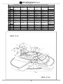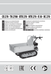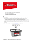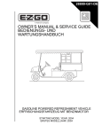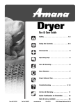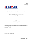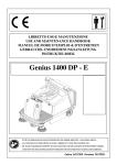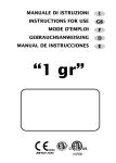
1
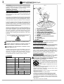
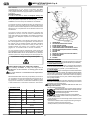
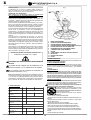
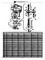
DELTA "V" 90 - DELTA "V" 120
(1193164 - 1193156)
LISCIATRICE
TRUELLE MECANIQUE
SMOOTHING MACHINE
GLÄTTEMASCHINE
ALISIDORA
manuale uso manutenzione ricambi
manuel utilisation entretien pieces de rechange
Operating,maintenance, spare parts manual
Handbuch für Bedienung, Wartung und Ersatzteile
manual de uso, mantenimiento y recambios
IMER INTERNATIONAL S.p.A.
53036 POGGIBONSI (SIENA) loc. SALCETO
(ITALY)
tel. (0577) 97341 - fax (0577) 983304
R06 - 2005/03
Cod. 2288975
I
IMER INTERNATIONAL S.p.A.
DELTA "V" 90 - 120
Fig.1
Caro Cliente,
ci complimentiamo per il suo acquisto: la lisciatrice IMER,
risultato di anni di esperienza, è una macchina di massima
affidabilità e dotata di soluzione tecniche innovative.
OPERARE IN SICUREZZA.
E’ fondamentale ai fini della sicurezza leggere attentamente le seguenti istruzioni.
Il presente manuale di USO E MANUTENZIONE deve essere custodito dal responsabile di cantiere nella persona del
CAPOCANTIERE nel cantiere stesso, sempre disponibile per la
consultazione.
Il manuale è da considerarsi parte della macchina e deve essere
conservato per futuri riferimenti (EN 12100/2) fino alla distruzione della macchina stessa. In caso di danneggiamento o smarrimento potrà essere richiesto al costruttore un nuovo esemplare.
Il manuale contiene importanti indicazioni sulla preparazione del
cantiere, l’installazione, l’uso, le modalità di manutenzione e la
richiesta di parti di ricambio. Comunque è da ritenersi indispensabile una adeguata esperienza e conoscenza della macchina
da parte del montatore e dell’utilizzatore.
Affinchè sia possibile garantire la sicurezza dell’operatore, la
sicurezza di funzionamento e una lunga durata della macchina
devono essere rispettate le istruzioni del manuale, unitamente
alle norme di sicurezza e prevenzione degli infortuni sul lavoro
secondo la legislazione vigente (uso di calzature e abbigliamento adeguati, uso di elmetti, guanti ed occhiali sec. D.P.R. 164 e
D.P.R. 547.
1
MANUBRIO DI COMANDO
2
LEVA ACCELERATORE/SPEGNIMENTO
3
LEVA COMANDO SOLLEVAMENTO PALE
4
POMELLO REGOLAZIONE ALTEZZA PALE
5
LEVA REGISTRO ALTEZZA MANUBRIO
6
ACCENSIONE MOTORE (SISTEMA A STRAPPO)
7
CAMPANELLA DI SOLLEVAMENTO
8
MOTORE
9
MARMITTA CON GRIGLIA DI PROTEZIONE
10 RIDUTTORE
11 PROTEZIONE PALE
12 PALE
2. NORME DI PROGETTO
La LISCIATRICE IMER è stata progettata e costruita applicando le
seguenti norme:EN 89/392; 91/368 CEE; D.P.R.547/55.
3. LIVELLO EMISSIONE SONORA
Livello emissione sonora all'orecchio dell'operatore(livello pressione
acustica continuo equivalente ponderato "A" ): la lisciatrice Imer ha
un livello di emissione di dB(A) 85 = (mot.HONDA GXV160).
4. TIPOLOGIA DI LAVORO
La macchina è progettata per la lisciatura di pavimenti o piani orizzontali, realizzati in calcestruzzo o materiali simili. Devono essere
usate solo pale appropriate secondo le specifiche IMER. Non si
devono lisciare manufatti realizzati con materiali collosi, o
semiliquidi, pavimenti con armature metalliche sporgenti o in presenza di materiali che possono essere proiettati dalle pale.
5. MISURE DI SICUREZZA
- La LISCIATRICE IMER è stata progettata per lavorare in cantieri
edili in condizioni normali di illuminazione solare o in condizioni di
illuminazione naturale o artificiale non inferiore a 500 LUX.
Non deve essere usata in ambienti ove esista pericolo di esplosioni o incendio o in ambienti di scavi sotterranei.
- Non asportare nessuna protezione.
Il simbolo rappresentato sull'etichetta sta' ad indicare che "È VIETATO AZIONARE LA MACCHINA SE
LE PROTEZIONI NON SONO MONTATE ED EFFICIENTI".
- Mantenere leggibili le segnalazioni dei vari avvertimenti.
- Far funzionare la macchina in zone sufficientemente areate, onde
evitare intossicazioni da gas di scarico.
- Attenzione nell' usare il carburante. I rifornimenti devono essere
eseguiti a motore spento e raffreddato.
- Assicurarsi che le pale non siano a contatto con nessun oggetto
prima di usare il motore.
- Trasportare la macchina con motore spento.
- Mantenere le impugnature asciutte e pulite da olio e grasso.
- Far funzionare la macchina in zone sufficientemente areate.
- Non iniziare il lavoro se la zona non è libera da persone o cose.
- Non lasciare che le persone si avvicinino mentre state lavorando.
- Quando si esegue qualsiasi tipo di manutenzione il motore deve
essere spento.
- Non lasciare la macchina incustodita.
Particolare attenzione deve essere fatta alle avvertenze
contrassegnate con questo simbolo :
MANTENERE SEMPRE LEGGIBILI LE SEGNALAZIONI
È vietato apportare modifiche di qualsiasi natura alla
struttura metallica o impiantistica della macchina.
È sconsigliato l'uso della macchina in ambienti con temperature inferiori a 0° C.
La IMER International declina ogni responsabilità in caso di non
osservanza delle leggi che regolano l’uso di tali apparecchi, in
particolare: uso improprio, difetti di alimentazione, carenza di
manutenzione, modifiche non autorizzate, inosservanza parziale o totale delle istruzioni contenute in questo manuale.
1. DATI TECNICI
DELTA 90
Giri pale
Diametro max pale
giri/min
mm
DELTA 120
min 50 / max 110
900
1200
N° pale
N°
4
Potenza motore
Kw
3.7
Giri max motore
giri/min
3600
Avviamento motore
manuale
Avanzamento
manuale
Peso
kg
91
106
Peso per trasporto
kg
106
126
2
IMER INTERNATIONAL S.p.A.
DELTA "V" 90 - 120
9.5 FINITURA
Quando la superficie lisciata è leggermente indurita, si può cominciare la finitura. All' inizio inclinare leggermente le pale di circa
4,6 mm. Dopo ogni passata di finitura, aumentare l' inclinazione
delle pale ed aumentare la velocità della macchina secondo la
durezza che si vuole ottenere.
Per livellare una depressione o un dosso, è sufficiente passare
la macchina avanti e indietro su questa zona fino ad aver ottenuto la livellazione desiderata.
9.6 FINITURA MEDIANTE DISCO DI LISCIATURA
Allo scopo di ottenere un grado di finitura ancora più elevato, è
possibile applicare il disco di lisciatura cod. 1193300 (optional,
installabile solo ed esclusivamente sul modello DELTA "V" 90).
Questo accessorio va montato sotto le pale di finitura e
non è applicabile alle pale universali o a quelle di
sgrossatura.
Il montaggio si effettua a macchina spenta, equipaggiata con le
pale di finitura, appoggiando il disco di lisciatura al suolo e
sovrapponendoci la lisciatrice, avendo cura di far coincidere le
pale con le battute presenti sul disco medesimo. Avviare la macchina per incominciare il lavoro, l'incastro tra le pale di finitura ed
il disco di lisciatura avverrà in modo automatico (in quanto le
battute sono orientate nello stesso senso di rotazione delle pale).
10. MANUTENZIONE
Attenzione!! Prima di qualsiasi manutenzione occorre
sempre spengere la macchina.
10.1 PRIMA REGOLAZIONE GIRI E CARBURAZIONE
MOTORE (rif.fig.5 - 6 )
Per eseguire la regolazione dei giri o la taratura della carburazione
del motore in sicurezza, le pale di lisciatura devono essere
smontate.Togliere la vite (rif.1 fig.5) e la rondella, sfilare il mozzo
(rif.2 fig.5) completo di pale, la linguetta (rif.3 fig.5) ed il piattello
(rif.4 fig.5).
Appoggiare la macchina a terra. Controllare che non vi siano
interferenze con l' albero riduttore.
Attenersi alle istruzioni del costruttore del motore per le
regolazioni da eseguire. Controllare i giri del motore con contagiri
elettronico (fig.6).
Assicurarsi che, con il motore tarato al minimo numero di giri,
l'albero riduttore non ruoti assolutamente. Terminate le varie
regolazioni, rimontare il piattello (rif.4 fig.5), la linguetta (rif.3 fig.5),
il mozzo con le pale (rif.2 fig.5) bloccando con la vite (rif.1 fig.5)
e la rondella.
10.2 MANUTENZIONI GENERALI
- Motore endotermico attenersi alle istruzioni della casa
costruttrice.
- Non abbandonare la macchina all' aperto, ma lasciarla al riparo
dalle intemperie.
- Ingrassare periodicamente le parti munite di ingrassatori.
- Controllare olio idraulico tipo 45c St 40°C della pompa.
- Sostituire olio SAE 140 riduttore dopo le prime 1000 ore di
lavoro; ripetere l' operazione ogni 3000 ore controllando periodicamente il livello.
L' olio esausto è rifiuto speciale. Come tale va gestito a
termini di legge.
- Pulire la macchina a fine lavoro per evitare incrostazioni.
- Per la sostituzione di parti guaste usare esclusivamente ricambi originali.
11. INCONVENIENTI / CAUSE / RIMEDI
INCONVENIENTI
CAUSE
RIMEDI
La leva di
Azionarla inserendo
accelerazione non è l' apposito fermo di
azionata
"minimo"
Il motore non si
avvia
Ripristinare livello
Manca carburante
Vedere libretto
motore
Le pale non
La frizione è usurata Sostituirla
ruotano
Livello olio
Ripristinarlo
insufficiente
Le pale non si
inclinano
Pomello di
Serrarlo
regolazione aperto
Rivolgersi all'
Se l' inconveniente persiste
Assistenza IMER
6. INSTALLAZIONE (rif.fig.2)
Togliere la macchina dall' imballo.
Per il sollevamento con un argano è necessario impegnare il gancio nell' apposita campanella.
Assicurarsi che non vi sia possibilità di scivolamento del gancio.
In sede di sollevamento, mani e piedi devono essere tenuti fuori
dall' area di pericolo.
Nessuno deve stazionare sotto il carico.
La macchina verrà scaricata nella postazione di lavoro con l' argano.
Deporre la macchina a terra.
La macchina è ora pronta per la messa in funzione.
7. CARATTERISTICHE
Manubrio regolabile per meglio soddisfare le esigenze dell' operatore e ridurre al minimo le dimensioni di ingombro.
E' munito di due impugnature di gomma e tutti i comandi sono di
comoda e facile azionabilità.
Cerchio di protezione in acciaio, permette di avvicinarsi il più
possibile agli ostacoli, garantendo la massima sicurezza all' operatore.
8. MONTAGGIO DELLE PALE
Sono disponibili tre tipi di pale che possono essere montate su
ogni modello. Il senso di rotazione delle pale è orario.
8.1 PALE UNIVERSALI (Montate di serie sulla macchina)
Avvitare le pale universali ai bracci esagonali servendosi delle viti
fornite con la macchina.
8.2 PALE DI FINITURA
Avvitare le pale di finitura ai bracci esagonali.
Contrariamente alle pale universali, le pale di finitura possono essere usate da ambo i lati, per cui non è necessario verificare il
senso di rotazione.
8.3 PALE DI SGROSSATURA
Le pale di sgrossatura vengono fissate sotto le pale di finitura per
mezzo di una clip.
9. USO (rif.fig.3)
Leggere ed applicare scrupolosamente le istruzioni del costruttore
del motore.
Avviamento: la leva di accelerazione è del tipo antinfortunistico
(rif.2 fig.1), a uomo presente; per avviare il motore si deve porre la
leva piccola (rif.1) in posizione di "fermo innestato" o di "minimo".
Solo dopo questa operazione attenersi ai consigli del costruttore
del motore per l' avviamento.
Accelerando il motore il fermo si disinnesta automaticamente e
lasciando completamente la leva di accelerazione il motore si spegne.
Attenzione!! Con la macchina in posizione "fermo innesto" o
di "minimo", le pale non devono girare; è quindi importante
ai fini della sicurezza la regolazione del minimo motore.
(Vedere istruzioni costruttore).
9.1 REGOLAZIONE INCLINAZIONE PALE
La regolazione inclinazione pale è di tipo oleodinamico; agendo
sulla leva della pompa si predispongono la pale in modo uniforme
all' inclinazione di lavoro necessaria.
La valvola posta sulla pompa permette, con una semplice manovra,
di riportare le pale in piano o variare l' angolo di inclinazione delle
stesse durante il lavoro.
9.2 TRASMISSIONE
Il motore è flangiato sul riduttore a bagno d' olio per ridurre l' usura
degli organi di trasmissione. La frizione centrifuga permette di avviare progressivamente la rotazione delle pale e fermare la rotazione delle stesse quando il motore gira al minimo.
9.3 MANOVRA
Si esegue premendo o alzando il manubrio.Sinistra: premendo /
Destra: alzando.In fase di lavoro si consiglia di seguire lo schema
riportato in fig.4 .
9.4 SGROSSATURA
Preparare il calcestruzzo come per una lisciatura manuale.
Assicurarsi di avere una superficie ben livellata (si raccomanda l'
uso di una staggia o meglio ancora di una staggia vibrante.
Quando il calcestruzzo ha fatto una presa tale che l' operatore
possa camminarci sopra lasciando solo una leggera impronta (circa 3 mm), si può cominciare la lisciatura.
La lisciatura è fatta tenendo le pale praticamente in piano.
Si raccomanda di inclinare leggermente le pale durante le ultime
passate per evitare gli effetti di aspirazione e d' attrito che si creano
normalmente durante la lisciatura di una pavimentazione ancora
umida.
Lisciare sempre alla velocità più bassa consentita dalla macchina.
3
I
F
IMER INTERNATIONAL S.p.A.
DELTA "V" 90 - 120
Fig.1
Cher Client
Nous vous félicitons de votre achat: la TRUELLE MECANIQUE
IMER, résultat de plusieurs années d’expérience, est une
machine de grande fiabilité dotée de solutions techniques à
l’avant-garde.
OPERER EN SECURITE
Il est fondamental, pour travailler en toute sécurité, de
lire attentivement les instructions qui suivent.
Le présent manuel USAGE ET ENTRETIEN doit être conservé par
la responsable du chantier c’est-à-dire le chef de chantier en
personne, et doit toujours être disponible pour la consultation.
Le manuel doit être considéré comme partie intégrante de la
machine et doit être conservé pour les références futures (EN
12100/2) jusqu’à la destruction de la machine. En cas
d’endommagement ou de perte, un nouvel exemplaire pourra
être demandé au constructeur.
Le manuel contient des indications importantes sur la préparation
du chantier, l’installation, l’utilisation, les modalités d’entretien et
la demande de pièces de rechange. Une expérience appropriée
et une bonne connaissance de la machine de la part de
l’installateur et de l’utilisateur sont à considérées comme
indispensables.
Afin qu’il soit possible de garantir une sécurité absolue à
l’opérateur, une sécurité de fonctionnement et une longue durée
de vie de l’appareil, les instructions du manuel doivent être
respectées, ainsi que les normes de sûreté et de prévention
contre les accidents du travail selon la loi en vigueur (utilisation
de chaussures et de vêtements appropriés, de casques, gants,
lunettes et casque anti-bruit selon D. N°92-765/766/767 et L23384).
Le non-respect des indications contenues dans le présent manuel
est considéré comme un usage incorrect de l’appareil et par
conséquent, il exonère à tous les effets la société IMER
INTERNATIONAL de tout dommage à personnes et choses
pouvant en dériver.
1
2
3
4
5
6
7
8
9
10
11
12
2. NORMES DE PROJET
Le TRUELLE MECANIQUE IMER a été conçue et coustruite en
appliquant les normes suivantes: EN 392 (91/368 CEE).
3. NIVEAU D'EMISSION SONORE
Niveau d'emission sonore a l'oreille de l'operateur (niveau pression
acoustique continu equivalente pondere "A"):la truelle mecanique Imer a
un niveau d' èmission sonore de dB(A) 85 = mot.HONDA GXV160 (*).
3.1 NIVEAU SONORE DES BRUITS AÉRIENS EMIS
(ART.5 ARRÊTÉ 11/04/72)
Type homologé par le Ministere de l' Enuironnement.
(*) Delta 90:
Arrete N° (95 - 040) du 18/07/95
(*) Delta 120:
Arrete N° (95 - 041) du 18/07/95
avec un niveau sonore maximal observé de 74 dB(A).
4. TYPE DE TRAVAIL
La machien est conçue pour lisser les pavements et autres surfaces
horizontales en bèton matèriaux assimilès.
Les pales utilisèes doivent exclusivement et impèrativement rèpondre
aux caractèristiques IMER.
Ne pas lisser de surfaces collantes, semi-liquides, contenant des pierres
ou prèsentant des saillies d' èlèments mètalliques, et d' une manière
gènèrale tout matèriau prèsentant des risques de projection de dèbris et
d' èmoussement des pales.
5. MESURES DE SECURITE
- La TRUELLE MECANIQUE IMER IMER a été conçue pour travailler
dans des chantiers de construction dans des conditions normales d'
éclairage e avec et dans des Ateliers des conditions d’éclairage naturel
ou artificiel superieur á 500 LUX.
Elle ne doit pas être utilisée dans des milieux à risques d’explosions
ou des incendies ou de fouilles souterraines.
N' enlever aucune protection.
Le symbole représenté sur l'étiquette indique qu'"IL EST
INTERDIT D'ACTIONNER LA MACHINE SI LES
PROTECTIONS NE SONT PAS MONTEES ET
EFFICACES".
- Maintenir lisibles les signalisations des diffèrents
avertissements.
- Employer des vêtements et des protections indiquès (casques antibruit, chaussures anti-écrasement).
- Faire attention á l' emploi du carburant qui doit être mis quand le moteur
est froid.
- S' assurer que les aubes ne soient au contact d' aucun objet avant d'
employer le moteur.
Il faut prêter une attention toute particulière aux notes
précédées de ce symbole:
LES SIGNALISATIONS DOIVENT TOUJOURS ETRE BIEN
LISIBLES.
Il est interdit d’apporter des modifications, de quelque
nature que ce soit, à la structure métallique ou à
l’ingénierie de la machine.
L'usage de la machine est déconseillé dans de endroits
avec températures inférieures a 0°C.
La société IMER INTERNATIONAL décline toute responsabilité en
cas de non-respect des lois régissant l’utilisation de ces appareils,
en particulier: usage impropre, défauts d’alimentation, manque
d’entretien, modifications non autorisées, non-respect partiel ou
total des instructions contenues dans ce manuel.
1. DONNES TECHNIQUES
D ELTA 90
D ELTA 120
Vitess de rotation
des aubes
nbre
t/min
D iamètre maxi
aubes
mm
Nbre d' aubes
N°
4
Puisanse moteur
Kw
3.7
nbre
t/min
3600
Tours maxi. moteur
min 50 / max 110
900
1200
Mise en marche
moteur
manuelle
Avance
manuelle
Poids
kg
91
106
Poids pour
transport
kg
106
126
GUIDON DE COMMANDE
POIGNEE ACCELERATION/EXTINCTION
LEVIER DE COMMANDE LEVAGE DES PALES
MANETTE DE COMMANDE LEVAGE DES PALES
LEVIER DE REGLAGE HAUTEUR DU GUIDON
DEMARRAGE MOTEUR (MANUEL)
ARCEAU DE LEVAGE
MOTEUR
POT D' ECHAPPEMENT AVEC GRILLE
DE PROTECTION
REDUCTEUR
PROTECTION DES PALES
PALES
4
F
IMER INTERNATIONAL S.p.A.
DELTA "V" 90 - 120
uniquement une empreinte légère (environ 3 mm), on peut
commencer le lissage.
Le lissage est effectuée en tenant les presque horizontalement.
On récomande d' incliner légèrement les aubes pendant les
derniéres passes pour éviter les effets d' aspiration et de
frottement se présentant pendant le lissage d' une pavage encore
humide.
Lisser toujours à la vitesse la plus basse admise par la machine.
9.5 FINISSAGE
Quand la surface lissée s' est legèrement durcie, on peut
commencer le finissage. Au début incliner les aubes d' environ
4.6 mm.
Après chaque passe de finissage augmenter l' inclinaison des
aubes et la vitesse de la machine selon la dureté que l' on veut
obtenir.
Pour niveler une flache ou une bosse, il suffit de passer la
machine d' avant en arrière sur cette zone jusqu' au nivellement
désiré.
9.6 FINITION PAR DISQUE DE LISSAGE
Pour obtenir un degré de finition encore plus élevé, appliquer le
disque de lissage cod. 1193300 (optionnel, installable
uniquement sur le modèle DELTA “V” 90).
Cet accessoire doit être monté sous les pales de finition
et n’est pas applicable aux pales universelles et de
dégrossissage.
Le montage doit être effectué machine arrêtée, équipée des
pales de finition, en appuyant le disque de lissage au sol et en
superposant la lisseuse, en ayant soin de faire coïncider les
pales avec les butées se trouvant sur le disque. Démarrer la
machine pour commencer le travail, l’encastrement des pales
de finition et du disque de lissage se fera en mode automatique
(car les butées sont orientées dans le même sens de rotation
que les pales).
10. ENTRETIEN
Attention !! Eteindre la machine avant toute opération
d'entretien.
10.1 PREMIER REGLAGE DU REGIME ET DE LA
CARBURATION DU MOTEUR (ref. fig. 5-6)
Pour régler le régime ou la carburation du moteur en toute sécurité,
démonter préalablement les pales de lissage: enlever la vis (ref.
1 fig.5) et la rondelle, désenfiler le moyeu (ref. 2 fig.5) avec les
pales, la languette (ref. 3 fig.5) et le plateau (ref. 4 fig.5).
Poser la machine par terre. Contrôler qu'il n'y ait pas d'obstacles
gênant l'arbre réducteur.
Respecter les instructions du constructeur du moteur pour les
réglages. Contrôler le régime du moteur à l'aide d'un comptetours électronique de proximité, placé près du câble d'allumage
de la bougie (fig. 6 ).
S'assurer que l'arbre réducteur ne tourne pas du tout lorsque le
régime du moteur est réglé au minimum. Après avoir effectué les
différents réglages, remonter le plateau (ref. 4 fig.5), la languette
(ref. 3 fig.5), le moyeu avec les pales (ref. 2 fig.5) et bloquer
avec la vis (ref. 1 fig.5) et la rondelle.
10.2 ENTRETIEN GENERAL
- Remplacer les pièces usées ou endommagées avee despiéces
de rechange d' origine.
- Moteur à combustion interne: suivre les instructions du fabricant.
- Ne pas abandonner la machine en plein air. La mettre à l' abri
des intepéries.
- Graisser périodiquement les parties pourveus de graisseurs.
- contrôler l' huile hidraulique type 45c St 40°C de la pompe.
- Remplacer l' huile SAE 140 du réducteur aprèr les premières
1000 heures de service; répéter l' opération toutes les 3000
heures en contrôlant périodiquement son niveau.
L' huile esée est un déchet spécial. Elle doit être éliminée
comme telle suivant les termes de la loi.
- A la fin du travail nettoyer la machine pour éviter les
encrasements.
- Pour le remplacement des pièces endommagées, utiliser
exclusivement des pièces de rechange d' origine.
11. INCONVENIENTS / CAUSES / REMEDES
- Transporter la machine avec le moteur arrêtè.
- Maintenir les poignèes sêches et propes, sans huile et graisse.
- Faire marcher la machine dans des zones assez aèrèes.
- Ne pas commencer le travail si la zone n' est pas libre de persones ou
choses.
- Ne pas laisser les personnes s' approcher pendant le travail.
- Pendant l' exècution de tout type d' entretien le moteur doit être arrêtè.
- Ne pas laisser la machine sans surveillance.
6. INSTALLATION (rif.fig.2)
Après avoir ôtè l' emballage, la machine peut être dèchargèe.
Pour le soulèvement avec un treuil, il est nècessaire de positionner le
crochet à l' endroit indiquè.
S' assurer que le crochet ne puisse pas glisser.
Au moment du soulèvement, mains et pieds doivent être èloignès de la
zone de danger.
Personne ne doit stationner sous la charge.
La machine sera dèchargèe à l' emplacement de travail avec le truil.
La machine ne peut descendre des plans inclinès ètant donnè qu'elle
n'est pas dotèe de dispositif de freinage.
Dèposer la machine au sol.
Oter le câble portant.
La machine est prête pour la mise en service.
7. CARACTERISTIQUES
Guidon pliable pour mieux rèpondre aux exigences de l' opèrateur et
pour rèduire au minimun les dimensions d' encombrement.
Il est pourvu de deux poignèes en caoutchouc et les commandes peuvent
être effectuèes facilement.
Cercle de protection en acier, permet de s' approcher autant que possible
des obstacles, garantissant la sècuritè maximale de l' opèrateur.
8. MONTAGE DES AUBES
Trois types d' aubes sont disponibles pouvant être installèes sur chaque
modèle.
La rotation des aubes se fait dans le sens des aiguilles d' une montre.
8.1 AUBES COMBINEES
Visser les aubes combinèes aux bras hexagonaux à l' aide des vis fournies
avec la machine.
S' assurer que le bord pliè des aubes tourne dans la direction approprièe.
8.2 AUBES DE FINISSAGE
Visser les aubes de finissage aux bras hexagonaux.
Contrairement aux aubes combinèes, les aubes de finissage peuvent être
employèes des deux côtès, ainsi il n' est pas nècessaire de vèrifier la
direction de rotation.
8.3 AUBES DE DEGROSSISSAGE
Les aubes de lissage sont fixèes au-dessous des aubes de finissage par
l' intermèdiaire d' une agrafe.
9. USAGE (rif.fig.3)
Lire et suivre scigneusement les instructiens du frabricant du moteur.
Dèmarrage le levier d' accèlèration est du type pour la prèvention des
accidents (rif.2 fig.1), en prèsence d' homme. Pour dèmarrer le moteur
positionner de sécurité (rif.1) sur "arrêt engage" ou "ralenti".
Uniquement après cette opèration il faut suivre les rècommandations du
frabricant du moteur pour le dèmarrage.En accèlèrant le moteur le levier
de sécurité se dègage automatiquement et, laissant complètement le levier
d' accèlèration, le moteur s' arrête.
Attention!! Avec la machine dans la position "arrêt engage" ou
"ralenti", les aubes ne doivent pas tourner; pour des raisons de
sècuritè le règlage du moteur est important.
(Voir instructions du fabricant).
9.1 REGLAGE DE L' INCLINAISON DES AUBES
Règlage de l' inclinaison des aubes de type olèodynanique; en agissant
sur le levier de la pompe on prèpare les aubes uniformèment à l' inclinaison
de travail nècessaire.
La soupape placèe sur la pompa permet, par une simple opèration, de
placer de nouveau les aubes horizontalement ou de charger l' angle d'
inclinaison de celles-ci pedant le travail.
9.2 TRASMISSION
Le moteur est à brides sur le rèducteur à bain d' huile pour rèduire
' usure des organes de trasmission. L' embrayage centrifughe entre le
moteur et le rèducteur permet de commencer progressivement la rotation
des aubes et d' arrêter leur rotation quand le moteur tourne au ralenti.
9.3 MANOEUVRE
Effectuée en appuyant ou levant le guidon. Guche: en appuyant - Droite:
en levant. Pendant le travil il faut suivre le schéma ci dessous fig.4.
9.4 DEGROSSISSAGE
Préparer le béton comme pour un lissage manuel. S' assurer d' avoir une
surface bien nivelée (on récommande l' emploi d' une barre ou bien d'
une barre vibrante).
Quand le béton a pris de façon que l' opérateur puisse y marcher laissant
INCONVENIENTS
Le moteur ne
démarre pas.
Les pales ne
tournent pas.
Les pales ne
s'inclinent pas.
CAUSES
Le levier
d'accélération n'a
pas été actionné.
Absence de
carburant.
L'embrayage est
usé.
Le niveau de l'huile
est insuffisant.
Le pommeau de
réglage est ouvert.
Si l' inconvénient persiste
5
REMEDES
Actionner le levier
en introduisant l'arrêt
de "minimum".
Rétablir le niveau.
Voir livret du
moteur.
Remplacer
l'embrayage.
Faire l'appoint
d'huile.
Serrer le pommeau.
S'adresser au
service d'assistance
IMER
GB
IMER INTERNATIONAL S.p.A.
DELTA "V" 90 - 120
Dear customer,
congratulations on your choice of purchase: the IMER
SMOOTHING MACHINE, the result of years of experience, is
a very reliable machine tool equipped with all the latest technical
innovations.
WORKING IN SAFETY
In order to be able to work in complete safety, the
following instructions must be read carefully
This OPERATING AND MAINTENANCE manual must be kept on
site by the person responsible for the site, e.g. the YARD
FOREMAN, and must always be available for consultation.
Fig.1
The manual should be considered as being an integral part of
the machine, and must be kept for future reference (EN 12100/
2) until the machine itself is disposed of. If the manual becomes
damaged or lost, a replacement can be obtained from the saw
manufacturer.
The manual contains important information regarding the
preparation of the site, use of the machine, maintenance and
spare parts ordering. Nevertheless, the installer and operator
must both have adequate experience and knowledge of the
machine.
In order that the safety of the operator, safe working and long
life of the equipment can all be guaranteed, the instructions in
this manual must be followed together with safety standards
and health and safety at work laws currently in force (use of
suitable footwear and clothing, use of helmets, gloves and
goggles, etc. in accordance with S.I. N°3073 of 30/11/92).
1
2
3
4
5
6
7
8
9
10
11
12
Any non-compliance with the requirements of this manual will
be considered as improper use of the equipment, consequently
IMER INTERNATIONAL will be exonerated from any damages
caused to persons or things resulting from said improper use.
Special attention must be given to warnings with this symbol:
2. DESIGN STANDARDS
The IMER Smoothing machine has been designed and constructed
in accordance with the following standards:EN 392 (91/368CEE).
3. NOISE EMISSION LEVEL
noise emission level read at operator's post(equivalent weighted
continuos sound pressure"a"): the Imer smothing machine has a
noise emission level of (a) 85 dB = (mot. HONDA GXV160).
4. TYPE OF WORK
The machine is designed for smoothing floors and horizontal surfaces
made of concrete or similar materials. Only IMER specification blades
must be used. Products must not be smoothed which are made of
tacky or semi-liquid materials, or with stone inclusions or projecting
iron rod reinforcements and in any case, liable to vestigial projction
risk or grating of blades.
5. SAFETY MEASURES
- The IMER Smoothing machine has been designed to work on building
sites under normal daylight conditions and in workshops with natural or
artificial lighting of not less than 500 lux.
It must never be used in explosion risk areas or fires or in
underground excavations.
-Use ear protectors and safety shoes.
This symbol appearingon the label indicates that THE
MACHINE MUST NOT BE USED IF THE PROTECTIVE
COVERS ARE NOT MOUNTED OR EFFICIENT.
- Do not remove the guards.
- To keep the different warning signals readable.
- To wear suitable clothes and protections. (Fars
protectors, safety shoes).
- To pay attention to fuel use. Rufuellings shall be carried out when
the engine is cold.
- To be sure the blades contact no object before using the engine.
- To move the machine when the engine is off.
- To keep handles dry and free from oil and grease.
ALWAYS MAKE SURE THAT SIGNS ARE LEGIBLE
It is strictly forbidden to carry out any form of
modification to the structure or working parts of the
machine.
Use of the machine is unadvisable with temperatures
below 0°C.
IMER INTERNATIONAL decline any responsibility in the case of
non-compliance with laws and standards governing the use of
this equipment. In particular: improper use, defective power
supply, lack of maintenance, unauthorized modifications, partial
or total inobservance of instructions contained in this manual.
1. TECHNICAL DATA
DELTA 90
Blade rpm
rpm
Max. blade diameter
mm
DELTA 120
min 50 / max 110
900
1200
Number of blade
N°
4
Motor rating
Kw
3.7
Max. motor rpm
rpm
3600
Motor starting
manual
Movement
manual
Weight
kg
91
106
Weight for transport
kg
106
126
HANDLEBAR
ACCELERATOR/SHUTOFF LEVER
BLADE ASCENT LEVER
BLADE HEIGHT ADJSTMENT KNOB
HANDLEBAR HEIGHT ADJUSTMENT LEVER
ENGINE IGNITION (WITH RECOIL STARTER)
LIFTING BAR
ENGINE
EXHAUST PIPE WITH PROTECTION GRILLE
REDUCTION GEAR
BLADE GUARD
BLADES
6
IMER INTERNATIONAL S.p.A.
DELTA "V" 90 - 120
GB
9.5 FINISHING
When the smooth surface has sligtly hardened, you can begin
finishing. At first slightly lean the blades by about 4.6 mm. After
any finishing pass, increase the blades tilt and increase the
machine speed according to the hardness you wish to reach.
To grade a depression or a bump it is sufficient to move the
machine to and fro on this area till the desired grading is reached.
9.6 FINISHING BY MEANS OF FLOAT DISK
To achieve optimal finishing standards, the power float disk
(code no. 1193300) can be applied (optional; installation
possible on model DELTA “V” 90 only).
This accessory should be fitted below the floating
blades and cannot be applied on universal or roughing
blade s.
Assembly must be performed with the machine switched off,
fitted with the finishing blades, placing the floating disk on the
floor and mounting the power float from above, taking care to
align the blades with the stops on the disk. Start up the machine
to begin work and engage the finishing blades and smoothing
disk (this is automatic as the stops are positioned in the same
direction of rotation as the blades).
10. MAINTENANCE
CAUTION! - The machine must always be switched off
before carrying out any maintenance operations.
10.1 INITIAL RPM ADJUSTMENT AND ENGINE TIMING(fig
5-6)
To adjust rpm or engine timing in safety, remove smoothing blades.
Remove screw (ref.1fig.5) and washer, slide off hub (ref.2
fig.5) complete with blades, key (ref.3 fig.5) and disc (ref.4
fig.5).
Place the machine on the ground. Check that the reduction gear
shaft is not obstructed.
Follow manufacturer's instructions for engine adjustment. Check
engine rpm by means of a noncontact tachometer, placed near
the spark plug cable (fig.6)
With the engine set to idling speed, ensure that the reduction
gear shaft does not rotate. Once adjustment is completed, refit
disc (ref.4 fig.5), key (ref.3 fig.5), hub with blades (ref.2 fig.5)
and secure with screw (ref.1 fig.5) and washer.
10.2 GENERAL MAINTENANCE
Internal combustion engine: follow the manufacturer' s
instructions.
- Do not abandon the machine in the open air; proteet it against
weather.
- Periodically grease the parts provided with lubricators.
- Check hidraulic oil type 45c St 40°C of the pump.
- Replace SAE 140 oil of the gear after the first 1000 working
hours; repeat the operation every 3000 checking its level
periodically.
Used oil is classed as special waste. As such, it must be
disposed of in accordance with the laws in force.
- Clean the machine at the end of the work in order to avoid
deposits.
- Use original spares only when replacing faulty components.
11. TROUBLESHOOTING / CAUSE / REMEDY
FAULT
CAUSE
REMEDY
- activate lever by
- acceleration lever
engaging the relative
not activated
idling safety lock
motor does not
- top up fuel
start
- no fuel
- refer to motor
instruction booklet
blades do not
- clutch is worn
- replace clutch
rotate
- insufficient oil
- top up oil
blades do not
- adjustment knob is
- tighten knob
incline
loose
refer to the IMER
If problem persists
service centre
6. INSTALLATION (fig.2 )
When the packing has been removed from the machine it can be
unloaded.
When using a lifting device, the hook must be placed in the lifting
eye provided.
Ensure that the hook cannot slide.
During lifting operations keep hands and feet away from the danger
zone.
Do not under any circumstances allow anyone to stand under the
supended load.
The machine will be placed in its working area by the lifting device.
Place the machine on the ground.
Remove the lifting cables.
The machine is now ready to work.
7. CARACTERISTICS
Handle bar is adjstable to meet the operator' s requirements and
minimize the overall dimensions.
It is provided with two rubber handles and all controls can be operated
easily.
Steel protection ring, permits to approach obstacles, assuring the
greatest safety for the operator.
8. BLADE INSTALLATION
Three types of blades are available that can be installed on any model.
The blade direction of rotation is clockwise.
8.1 COMBINED BLADES
Fasten the combined blades to hexagonal arms by means of the
screws supplied with the machine.
Be sure the bent edge of the blades rotates in the right direction.
8.2 FINISHING BLADES
Fasten the finishing blades to hexagonal arms.
Contrary to combined blades, the finishing blades can be used on
both sides, therefore it is not necessary to check the direction of
rotation.
8.3 ROUGHING BLADES
Smoothing blades are fastened under finishing blades by means of
a clip.
9. USE (fig.3)
Read and follow the engine manufacturer' s instructions carefully.
Starting: The acceleration lever is accident prevention type (rif.2
fig.1) when it is attended; to start the engine, position the small lever
(rif.1) on "Retainer engaged" or "Idling". Only after this operation
follow the engine manufacturer' s recommendations for starting.
By accelerating the engine the retainer disengages automatically and
leaving the acceleration lever completely, the engine stops.
CAREFUL!! With the machine positioned on "Retainer
engaged" or "Idling", blades shall not rotate; therefore, for
safety' s sake the engine idling adjustment is important. (See
the manufacturer' s instructions).
9.1 BLADE TILTING ADJUSTMENT
Oleodynamic type; by operating on the pump lever the blades are
set for the required working tilting evenly.
The valve located on the pump permits, by a simple operation, to
place again the blades horizontally or to change the angle of inclination
during the work.
9.2 DRIVE
The engine is flanged on the gear in oil bath to reduce the wear of
the driving elements. The centrifugal clutch between the engine and
the gear permits to start the blade rotation progressively and to stop
their rotation when the engine idles.
9.3 CONTROL
Carried out by pushing or lifting the andle. Left: by pushing - Right:
by lifting.
During the work we recommend to keep to the following diagram
fig.4.
9.4 ROUGHING
Prepare concrete as for a manual smoothing. Make sure the surface
is smooth (is recommended the use of a bar or of a vibrating bar).
When concrete has set so that operator may walk on it leaving only
a slight footprint (about 3 mm), you can begin smoothing.
Smoothing is made by keeping blades almost horizontally.
Slightly lean the blades during the last passes in order to avoid suction
and friction effects occurring during the smoothing of a still damp
paving.
Always smooth at the lowest speed allowed by the machine.
7
D
IMER INTERNATIONAL S.p.A.
DELTA "V" 90 - 120
Sehr geehrter Kunde, wir beglückwünschen Sie zu Ihrem Kauf. Die
Glättemaschine IMER, Ergebnis der langjährigen Erfahrung des
Unternehmens, bietet höchste Zuverlässigkeit und ist mit innovativen
technischen Lösungen ausgestattet.
ARBEITSSICHERHEIT
Zur Gewährleistung der Arbeitssicherheit sind aufmerksam die
folgenden Anweisungen zu lesen.
Das vorliegende Bedienungs- und Wartungshandbuch ist von dem
Baustellenverantwortlichen in Person des Baustellenleiters auf der
Baustelle aufzubewahren und hat stets zur Einsicht bereitzuliegen.
Abb. 1
Das Handbuch ist als Teil der Glättemaschine zu betrachten und
ist für künftige Konsultationen (EN 12100/2) bis zur Zerstörung
der Glättemaschine aufzubewahren. Bei Beschädigung oder
Verlust ist vom Hersteller ein neues Exemplar anzufordern.
Das Handbuch enthält wichtige Hinweise zur Vorbereitung der
Baustelle sowie zu Installation, Benutzung, Wartung und
Ersatzteilbestellung. Eine angemessene Erfahrung und Kenntnis
im Umgang mit dem Mischer von Seiten des Monteurs und des
Benutzers ist unbedingt vorauszusetzen.
1
LENKER
2 GASHEBEL/AUSSCHALTHEBEL
3 HEBEL FLÜGELHUB
4 EINSTELLKNOPF FLÜGELHÖHE
5 EINSTELLHEBEL LENKERHÖHE
6 MOTORANLASSER (HANDSTARTVORRICHTUNG)
7 HEBEGLOCKE
8 MOTOR
9 AUSPUFFTOPF MIT SCHUTZGITTER
10 UNTERSETZUNGSGETRIEBE
11 SCHAUFELVERKLEIDUNG
12 FLÜGEL
2.PROJEKTNORMEN
Der IMER GLÄETTEMASCHINE wurde nach den folgenden Normen geplant
und konstruiert: I.E.C.34.4; EN 60204-1; EN 392 (91/368 CEE).
3.GERÄUSCHPEGEL
Der IMER GLÄETTEMASCHINE hat eine Schallemission von 74 dB(A).
4.EINSATZARTEN
Die Maschine ist für das Glätten von Fußböden und horizontalen Flächen aus
Beton und ähnlichen Materialien geplant. Dazu dürfen ausschließlich spezielle
Flügel gemäß IMER-Spezifikationen verwendet werden. Erzeugnisse aus klebrigen
oder halbflüssigen Materialien, Fußböden mit hervorstehenden Metallarmierungen
oder bei Vorhandensein von losem Material, das von den Fluegeln
herausgeschleudert werden kann, können nicht geglättet werden.
5.SICHERHEITSMASSNAHMEN
Der IMER-BETONGLÄTTER wurde für den Einsatz auf Baustellen unter normaler
Sonnenlichteinwirkung oder unter natürlichen oder künstlichen
Beleuchtungsbedingungen von mindestens 500 Lux entwickelt.
DieMaschinedarfaufkeinenFallinRäumenmitExplosions-undBrandgefahroderin
unterirdischenRäumeneingesetztwerden.
- Entfernen Sie keine der Schutzvorrichtungen.
Das auf dem Etikett abgebildete Symbol zeigt an, DASS DIE
MASCHINE
BEI
NICHT
MONTIERTEN
SCHUTZVORRICHTUNGEN NICHT BETRIEBEN WERDEN
DARF.
- Halten Sie die verschiedenen Hinweisschilder stets gut leserlich.
- Der IMER-Betonglätter darf nur betrieben werden, wenn alle Schutzvorrichtungen
montiert und diese perfekt leistungsfähig sind.
- Im Falle von defekten Anschlußkabeln darf die Maschine auf keinen Fall
betrieben werden.
- Auf Baustellen müssen die Anschlußleitungen so verlegt werden, daß sie nicht
beschädigt werden können. Stellen Sie den Betonglätter nicht auf die Kabel.
- Die Anschlußleitungen müssen außerdem so verlegt werden, daß die Verbinder
gegen eindringendes Wasser geschützt sind. Verwenden Sie ausschließlich
Verbinder mit Schutz gegen Wasserspritzer (IP55).
- Reparaturen der Elektroanlage dürfen nur von Fachpersonal ausgeführt werden.
Der Betonglätter darf während Wartungs- oder Reparaturarbeiten nicht
eingeschaltet werden.
- Innerhalb des Arbeitsbereiches müssen die Unfallschutznormen und die
Sicherheitsvorschriften eingehalten werden.
- Die elektrische Versorgungsanlage muß den Normen CEI-64-8 entsprechen
(Harmonisierungsdokument CENELEC HD384).
- Vor dem Einschalten des Motors sicherstellen, daß die Schaufeln keine
Gegenstände berühren.
- Vor dem Anlassen des Motors sicherstellen, daß die Schaufeln keine Gegenstände
berühren. - Transportieren Sie die Maschine bei abgestelltem Motor.
- Halten Sie den Griffteil sauber und öl- und fettfrei.
Um die Sicherheit des Bedieners, die Betriebssicherheit und eine
lange Standzeit der Glättemaschine gewährleisten zu können, sind
die Anweisungen des Handbuches sowie die Sicherheits und
Unfallverhütungsmaßnahmen nach der geltenden Gesetzgebung zu
befolgen (Tragen von Schutzschuhen, Schutzbekleidung,
Schutzhelm, Schutzhandschuhen und Schutzbrille)9.GSGV von
12.05.93.
Lesen Sie die mit diesem Symbol bezeichneten Abschnitte
mit besonderer Aufmerksamkeit:
Halten Sie alle Aufschriften stets perfekt lesbar.
An der Metallstruktur oder den Anlagenteilen der Maschine
dürfen keinerlei Änderungen angebracht werden.
Die Maschine sollte nicht in Umgebungen
Temperaturen unter 0° C benutzt werden.
mit
IMER INTERNATIONAL übernimmt keine Haftung bei
Nichteinhaltung der Gesetze zum Gebrauch von
Arbeitsausrüstungen, insbesondere bei zweckentfremdetem
Gebrauch, falscher Netzversorgung, fehlender Wartung, nicht
genehmigter Änderungen sowie teilweiser oder vollständiger
Nichtbefolgung der in diesem Handbuch enthaltenen Anweisungen.
1. TECHNISCHE DATEN
DELTA 90
Flügelumdrehungen
U/min
Max.
Flügeldurchmesser
mm
DELTA 120
min 50 / max 110
900
1200
Schaufelzahl
N°
4
Motorleistung
Kw
3.7
U/min
3600
Max. Motordrehzahl
Anlasser
manuell
Vorschub
manuell
Gewicht
kg
91
106
Transportgewicht
kg
106
126
8
IMER INTERNATIONAL S.p.A.
DELTA "V" 90 - 120
- Beginnen Sie erst mit der Arbeit, wenn der betreffende Bereich
9.4 GROBBEARBEITUNG
frei von Personen und Gegenständen ist.
Den Beton wie für das manuelle Glätten vorbereiten.
- Achten Sie darauf, daß sich während der Arbeit keine Personen
Sorgen Sie für eine gut nivellierte Oberfläche (es empfiehlt sich,
in der Nähe aufhalten.
einen Verdichter oder besser einen Rüttler zu verwenden).
- Führen Sie alle Wartungsarbeiten ausschließlich bei abgestelltem
Sobald der Beton soweit abgebunden ist, daß beim Betreten nur
ein leichter Abdruck (zirka 3 mm) zurückbleibt, kann mit dem
Motor aus.
Glätten begonnen werden.
- Lassen Sie die Maschine nicht unbeaufsichtigt stehen.
Für das Glätten werden die Schaufeln praktisch gerade gehalten.
6. INSTALLATION (Bez. Abb. 2)
Deneken Sie daran die Schaufeln für die letzten Durchgänge
Die Maschine aus der Verpackung nehmen.
leicht schräg zu stellen, damit der normalerweise beim Glätten
Für das Heben mit einer Winde wird der Haken an der speziellen
von noch feuchten Böden auftretende Ansaug- und Abriebeffekt
Glocke befestigt.
vermieden wird.
Stellen Sie sicher, daß der Haken während dem Hebevorgang nicht
Glätten Sie stets bei der niedrigsten Maschinengeschwindigkeit.
verrutschen kann.
9.5 FEINBEARBEITUNG
Sobald die geglättete Fläche leicht gehärtet ist, kann mit der
Halten Sie Hände und Füße während dem Heben außerhalb der
Feinbearbeitung begonnen werden.
Gefahrenzone.
Neigen Sie die Fluegeln anfangs um ungefähr 4,5 mm. Nach
Achten Sie unbedingt darauf, daß sich keine Personen unterhalb
jedem Feinbearbeitungsdurchgang je nach gewünschter Härte
der Last aufhalten.
die
Schägstellung
der
Schaufeln
und
die
Die Maschine wird mittels der Winde in Arbeitsposition abgeladen.
Maschinengeschwindigkeit erhöhen.
Die Maschine auf dem Boden abstellen.
Für das Nivellieren von Unebenheiten genügt es die Maschine an
Damit ist die Maschine betriebsbereit.
der betreffenden Stelle hin- und herzubewegen, bis die
gewünschte Ebenheit erhalten ist.
7. CHARAKTERISTIKEN
9.6 OBERFLÄCHENBEHANDLUNG MIT GLÄTTSCHEIBE
Verstellbare Lenkstange für optimale Anpassung an die
Eine noch feinere Oberflächenbehandlung ist mit der
Anforderungen des Benutzers und minimalen Raumbedarf.
Glättscheibe, Art.-Nr. 1193300, möglich (auf Wunsch erhältlich,
Mit zwei Griffteilen aus Gummi und einfach bedienbaren
Installation ausschließlich an Modell DELTA “V” 90).
Schaltelementen.
Dieses Zubehörteil kann nur unter die Schleiffflügel,
Schutzverkleidung aus Stahl, dank der die Maschine so weit wie
nicht
aber
unter
die
Universaloder
möglich an Hindernisse angenähert werden kann, ohne den Benutzer
Grobbehandlungsflügel montiert werden.
zu gefährden.
Die Glättscheibe zur Montage auf den Boden legen. Die
ausgeschaltete Maschine mit montierten Schleifflügeln so
8. MONTAGE DER FLÜGEL
darauf stellen, dass die Flügel mit den Anschlägen auf der
Es stehen drei fluegeltypen zur Verfügung, die an allen Modellen
Scheibe übereinstimmen. Die Maschine einschalten und mit der
eingebaut werden können. Die Drehrichtung der Schaufeln erfolgt
Arbeit beginnen. Schleifflügel und Glättscheibe rasten
im Uhrzeigersinn.
automatisch ein, da die Anschläge in der Richtung der
8.1 KOMBINATIONSGLÄTTEFLÜGEL
Flügelrehung orientiert sind.
(SERIENMÄSSIG AN DER MASCHINE EINGEBAUT)
10. WARTUNG
Die Kombinationsglätteflügel den mitgelieferten Schrauben an den
Achtung! Vor jedem Wartungseingriff stets die Maschine
Sechskantarmen befestigen.
ausschalten.
10.1 Erste Drehzahl- und Vergasereinstellung des Motors
8.2 NACHARBEITUNGLÄTTEFLÜGEL
(Bez. Abb.5 - 6)
Die Nacharbeitungsglätteflügel an den Sechskantarmen
Für die sichere Drehzahl- oder Vergasereinstellung müssen die
anschrauben.
Schaufeln ausgebaut werden. Die Schraube (Bez. 1 Abb.5) und
Im Gegensatz zu den Kombinationsglätteflügeln können die
die Unterlegscheibe entfernen, die Nabe (Bez. 2 Abb.5)
Nacharbeitungsglätteflügel beidseitig verwendet werden und folglich
zusammen mit den Schaufeln, die Lasche (Bez. 3 Abb.5) und
muß die Drehrichtung nicht kontrolliert werden.
den Teller (Bez. 4 Abb.5) abziehen.
8.3 VORARBEITUNGSGLÄTTEFLÜGEL
Die Maschine auf den Boden legen. Kontrollieren, ob
Interferenzen mit der Welle des Untersetzungsgetriebes vorliegen.
Die Vorarbeitungsglätteflugel werden mit einer Klammer unterhalb
Befolgen Sie für die durchzuführenden Einstellungen die
den Kombinationsglätteflügel befestigt.
Anweisungen des Motorherstellers. Kontrollieren Sie die
9. GEBRAUCH (Bez. Abb. 3)
Motordrehzahl mit einem elektronischen Drehzahlmesser (Abb.
Lesen und befolgen Sie genau die Anweisungen des
6 ). Sicherstellen, daß die Welle des Untersetzungsgetriebes bei
Motorherstellers.
auf Mindestdrehzahl eingestelltem Motor nicht dreht. Nachdem
Starten: der Gashebel ist unfallgeschützt (Bez.2, Abb.1) bei
die verschiedenen Einstellungen ausgeführt wurden, den Teller
anwesendem Benutzer; für das Starten des Motors den kleinen
(Bez. 4 Abb.5), die Lasche (Bez. 3 Abb.5) die Nabe mit den
Hebel (Bez.1) auf die Position “Arretierung eingekuppelt” oder
Fluegeln (Bez. 2 Abb.5) wieder einbauen und mit der Schraube
(Bez. 1 Abb.5) und der Unterlegscheibe befestigen.
“Minimum” stellen.
10.2 ALLGEMEINE WARTUNG
Erst nach diesem Vorgang die Anleitungen des Motorherstellers
- Für den endothermischen Motor die Anweisungen des
für das Starten befolgen.
Herstellers befolgen.
Beim Gasgeben kuppelt sich die Arretierung automatisch aus und
- Stellen Sie die Maschine nicht im Freien ab, damit sie keinen
beim vollkommenen Loslassen des Hebels geht der Motor aus.
Witterungseinflüsse ausgesetzt wird.
Achtung! Bei Maschine auf Position “Arretierung
- Das Hydrauliköl Typ 45c St 40°C der Pumpe kontrollieren.
eingekuppelt” oder “Minimum” dürfen die Schaufeln nicht
- Das Öl SAE 140 des Untersetzungsgetriebes nach den ersten
drehen; aus diesem Grund ist die Einstellung der
1000 Betriebsstunden wechseln; in der Folge alle 3000 Stunden
wechseln und regelmäßig den Stand kontrollieren.
Mindestdrehzahl des Motors für die Sicherheit wichtig.
Das verbrauchte Öl ist Sondermüll, der vorschriftsmäßig
(Siehe Anleitungen des Herstellers).
entsorgt werden muß.
9.1 EINSTELLUNG DER FLUEGELSCHRÄGE
Nach der Arbeit die Maschine säubern, damit Verkrustungen
Die Einstellung der Flügelschräge erfolgt öldynamisch; durch
vermieden werden. - Zum Austausch defekter Teile dürfen
Einwirken auf den Pumpenhebel werden die Schaufeln gleichmäßig
ausschließlich Original-Ersatzteile verwendet werden.
auf die erforderliche Arbeitsschräge eingestellt.
11. STÖRUNGEN / URSACHEN / ABHILFEN
Das an der Pumpe befindliche Ventil ermöglicht es, die Schaufeln
STÖRUNG
URSACHE
ABHILFE
mit einem einfachen Vorgang wieder gerade zu stellen oder den
Gashebel über
Gashebel ist nicht
Neigungswinkel während der Arbeit zu verändern.
Leerlaufsperre
betätigt
9.2 ANTRIEB
betätigen
Kein Motorstart
Der Motor ist an einem Untersetzungsgetriebe in Ölbad
Öl auffüllen
Kein
Kraftstoff
aufgeflanscht, um den Verschleiß der Antriebsorgane zu mindern.
Motorhandbuch
vorhanden
Die Fliehkraftkupplung ermöglicht die progressive Flügeldrehung und
einsehen
das Anhalten dieser Drehung, wenn der Motor mit Mindestdrehzahl
Kupplung
Flügelräder
Kupplung
abgenutzt
läuft.
auswechseln
drehen nicht
9.3 MANÖVER
Ölstand
Öl auffüllen
Flügelräder
Dieses erfolgt durch nach oben und unten bewegen der
unzureichend
schwenken nicht
Lenkstange. Links: nach unten bewegen/Rechts: nach oben
Regelknopf offen
Knopf schließen
bewegen. Während der Arbeit empfiehlt es sich das Schema
IMER-Kundendienst
Störung besteht weiterhin
verständigen
der Abb. 4, zu befolgen.
9
D
E
IMER INTERNATIONAL S.p.A.
DELTA "V" 90 - 120
Fig.1
Estimado cliente,
Le felicitamos por su compra: la Alisidora IMER, resultado de
años de experiencia, es una máquina absolutamente fiable y
dotada con soluciones técnicas innovadoras.
TRABAJAR CON SEGURIDAD
Para trabajar en condiciones seguras es fundamental
leer con atención las siguientes instrucciones.
El presente manual de USO Y MANTENIMIENTO tiene que ser
conservado por el responsable de las obras y, en concreto, por
el capataz, y, además, tiene que estar siempre disponible para
poderlo consultar en cualquier momento.
El manual debe considerarse parte de la máquina y, por lo tanto,
tiene que conservarse para poder efectuar cualquier consulta
(EN 12100/2) hasta que se destruya la máquina. Si se pierde o
se daña, se puede solicitar un nuevo ejemplar al fabricante.
El manual contiene importantes indicaciones sobre la preparación
de las obras, la instalación, el uso, las modalidades de
mantenimiento y la solicitud de piezas de recambio. De todas
formas, es indispensable que el encargado de la instalación y el
usuario tengan una experiencia y conocimiento adecuados de la
máquina.
Para garantizar la seguridad del operador y el correcto
funcionamiento y una larga duración del equipo se tienen que
respetar no sólo todas las instrucciones del manual sino también
las normas de seguridad y prevención de accidentes en el trabajo
establecidas por la legislación vigente (uso de calzado y ropas
adecuadas, empleo de cascos, guantes y gafas de protección;
R.D. 1435/92).
Se considera un uso indebido del equipo el hecho de no respetar
todo lo descrito en el presente manual y, por lo tanto, exime a
todos los efectos la empresa IMER INTERNATIONAL por cualquier
daño provocado a personas o cosas.
1
2
3
4
5
6
7
8
9
10
11
12
Se tiene que prestar una atención especial a las
indicaciones marcadas con el signo:
2. NORMAS DE PROYETTO
La alisidora IMER ha sido proyectada y fabricada en conformidad con las
siguientes normas: EN 392 (91/368CEE).
3. NIVEL DE EMISION SONORA
Nivel de emision sonora en el oido del operador (nivel de presion
acustica continuo equivalente ponderado "A"): la alisidora IMER
posee un nivel de emisión sonora de 85 dB (A) = (mot. HONDA
GXV160).
4. TIPO DE TRABAJO
La máquina ha sido proyectada para pulir pavimentos y superficies horizontales,
realizadas en hormigón o materiales análogos. Deberán ser utilizadas sólo aspas
adecuadas según las aspecificaciones IMER. La máquina no debe ser utilizada
para pulir manufacturas realizadas con materiales viscosos o semiliquidos, que
contengan piedras o armaduras sobresalientesde varillas de hierro o que, en
todo caso, comprten peligro de lanzamiento de residuos o choque de las aspas.
5. MEDIDAS DE SEGURIDAD
-La Alisidora IMER ha sido proyectada para trabajar en las obras de construcción
en condiciones normales de iluminación solar y en talleres de carpintería en
condiciones de iluminación natural o artificial no inferiores a 500 lux.
No se tiene que utilizar nunca en ambientes donde haya peligro de
explosión o incendios o en excavaciones subterráneas.
El símbolo ilustrado en la etiqueta indica que ESTA
PROHIBIDP ACCIONAR LA MAQUINA SI LAS
PROTECCIONES NO ESTAN MONTADAS Y EFICIENTES.
- No quitar ninguna protección.
- Mantener legibles las señales de las distintas
advertencias.
- Utilizar vestuario y protecciones adecuadas.
- Atención al usar el carburante. El abastecimiento se debe efctuar con el
motor frio.
- Asegurarse de que las palas no estén en contacto con ningún objeto
antes de utilizar el motor.
- Transportar la máquina con el motor apagado.
- Mantener las empuñaduras secas y limpias de aceite y de grasa.
- Hacer funcionar la máquina en zona suficientemente ventiladas.
- No comenzar el trabajo si la zona no está libre de personas o cosas.
- No permitir que las personas se acerquen mientras se está trabajando.
- Cuando se efectúa cualquier tipo de manutención el motor debe estar
apagado.
- No dejar la máquina sin custodia.
MANTENER LAS SEÑALIZACIONES PERFECTAMENTE
VISIBLES
Se prohíbe efectuar cualquier tipo de modificación en la
estructura metálica o en la instalación de la máquina.
No se aconseja el uso de la máquina en ambientes con
temperatura inferiores a 0° C.
IMER INTERNATIONAL declina toda responsabilidad cuando no
se respeten las leyes que reglamentan el uso de estos equipos,
y, en concreto: uso indebido, defectos de alimentación, falta de
mantenimiento, modificaciones no autorizadas e incumplimiento
total o parcial de las instrucciones ilustradas en este manual.
1. DATOS TÈCNICOS
DELTA 90
Revoluciones des
palas
rpm
Diàmetro màximo de
las palas
mm
DELTA 120
min 50 / max 110
900
1200
N° de la palas
N°
4
Potencia motor
Kw
3.7
Revoluciones màximas
del motor
rpm
3600
Arranque del motor
manual
Avance
manual
Peso
kg
91
106
Peso para el
transporte
kg
106
126
MANILLAR DE MANDO
PALANCA ACELERADOR/APAGADO
PALANCA MANDO LEVANTAMIENTO PALAS
BOTÓN ESFÉRICO MANDO LEVANTAMIENTO PALAS
PALANCA REGLAJE ALTURA MANILLAR
ENCENDIDO MOTOR (SISTEMA DE TIRÓN)
CAMPANILLA DE LEVANTAMIENTO
MOTOR
CATALIZADOR CON REJILLA DE PROTECCIÓN
REDUCTOR
PROTECCIÓN PALAS
PALAS
10
IMER INTERNATIONAL S.p.A.
DELTA "V" 90 - 120
9.5 PULIDO
Cuando la superficie alisada está ligerramente endurecida, se
puede empezar el pulido. Al inicio, inclinar ligeramente las palas
unos 4-6 mm. Después de cada pasada de pulido, aumentar la
inclinación de las palas y aumentar la velocidad de la máquina
según la dureza que se desea obtener.
Para nivelar una depresión o una protuberancia, es suficiente
pasar la máquina hacia adelante y hacia atrás sobre esta zona
hasta obtenido la nivelación deseada.
9.6 ACABADO CON DISCO DE ALISADO
Para obtener un acabado todavía más liso, es posible aplicar el
disco de alisado opcional cód. 1193300 (sólo se puede montar
en el modelo DELTA “V” 90).
Este accesorio no puede montarse en las palas
universales ni en las palas de desbaste sino que ha de
montarse debajo de las palas de acabado.
El disco de alisado se ha de montar con la máquina apagada y
equipada con las palas de acabado de la siguiente manera:
apoyar el disco al suelo y poner el alisador encima de manera
que sus palas coincidan con los topes del disco. Poner en
marcha la máquina pare empezar el trabajo: las palas de
acabado quedan automáticamente ensambladas con el disco
de alisado ya que los topes están orientados en el sentido de
rotación de las palas.
10. MANUTENCION
Atención!
Antes
de
cualquier
operación
de
mantenimiento siempre habrá que apagar la máquina.
10.1 PRIMERA REGULACION DE LAS REVOLUCIONES Y
CARBURACION DEL MOTOR (fig. 5 - 6).
Para realizar la regulación de las revoluciones o el reglaje de la
carburación del motor con plena seguridad, las palas de pulido
han de desmontarse. Quitar el tornillo (ref. 1 fig.5) y la arandela,
extraer el buje (ref. 2 fig.5) con las palas, la lengüeta (ref. 3 fig.5)
y el platillo (ref. 4 fig.5).
Apoyar la máquina en el suelo. Controlar que no hay interferencias
con el eje del reductor.
Seguir las instrucciones del fabricante del motor para las
regulaciones que se realicen. Controlar las revoluciones del
motor con cuentarrevoluciones electrónico de proximidad, situado
cerca del cable de encendido de la bujía (fig. 6).
Comprobar que, con el motor regulado al mínimo número de
revoluciones, el eje del reductor no gira. Una vez terminados los
reglajes oportunos, montar el platillo (ref. 4 fig.5), la lengüeta
(ref. 3 fig.5), el buje con las palas (ref. 2 fig.5), bloqueando con
el tornillo (ref. 1 fig.5) y la arandela.
10.2 MANUTENCION GENERAL
- Motor endotermico: atenerse a las instrucciones de la casa
constructora.
- No dejar la máquina al aire libre sino en lugar protegido de la
intemperie.
- Lubricar periodicamente las partes provistas de engrasadores.
- Controlar aceite hidraulico tipo 45c St 40°C de la bomba.
- Cambiar aceite SAE 140 reductor después de las primeras
1000 horas de trabajo; repetir la operación cada 3000 horas
controlando periódicamente el nivel del mismo.
El aceito utilizado se considera un residuo especial y,
por lo tanto, tiene que eliminarse en conformidad con
las leyes vigentes.
- Limpiar la máquina al final del trabajo para evitar que se former
incrustaciones.
- Cambiar las piezas desgastadas o averiadas con piezas de
recambio originales.
11. INCONVENIENTES / CAUSAS / REMEDIOS
6. INSTALACION (fig.2)
Despés de haber desembalado la máquina, se pude descargar.
Si se levanta con un cabrestante, hay que sujetar el gancho a la
correspondiente argolla.
Asegurarse de que el gancho no pueda soltarse.
Cuando se levante la alisidora, las manos y los pies tienen que estar fuera
del área de peligro.
Además, no tiene que haber nadie debajo de la alisidora.
La máquina tiene que descargarse en el lugar de trabajo deseado con
ayuda del cabrestante.
Dejar la máquina en el suelo.
Quitar el cable de elevación.
La máquina está lista para ser puesta en marcha.
7. CARACTERISTICAS
Manivela es regulabile para satisfacer mejor las exigencias del operador y
para reducir al minimo las dimensiones de la máquina.
Está provisto de dos empuñaduras de goma y todos los mandos son de
comodo y fácil accionamiento.
Cerco de protección de acero, permite acercarse lo más posible a los
obstaculos, garantizando la máxima seguridad al operador.
8. MONTAJE DE LAS PALAS
Existen tres tipos de palas que pueden ser montadas sobre cualquier
modelo.
La rotación de las palas es en el sentido de las agujas del reloj.
8.1 PALAS COMBINADAS
Atornillar las palas combinadas a los brazos hexagonales utilizando los
tornillos suministrados con la máquina.
Cerciorarse de que el borde replegado de las palas gire en el sentido justo.
8.2 PALAS DE PULIDO
Atornillar las palas de pulido a los brazos hexagonales.
Contrariamente a las palas combinadas, las palas de pulido pueden ser
utilizadas de ambos lados, por lo tanto no es necesario verificar el sentido
de rotación.
8.3 PALAS DE DESBASTE
La palas de alisadura son fijadas dabajo de las palas de pulido por medio
de un clip.
9. USO (fig.3)
Leer y aplicar escrupolosamente las instrucciones del constructor del motor.
Puesta en marcha: La palanca de aceleración es del tipo contra accidentes
(ref.2 fig.1) en presencia del operador; para dar arranque al motor, se debe
colocar la palanca pequeña (ref.1) en posición de "freno embragado" o de
"minimo".
Sólo después de esta operación atenerse, para el arranque, a los consejos
del constructor del motor.
Acelerando el motor, el freno se desembraga automaticamente y,
abandonando completamente la palanca de aceleración, el motor se para.
Atencion!! Con la máquina en posición de "freno embragado" o de
"minimo", las palas no deben girar; es pues importante, a los fines de
obtener seguridad, la regulación del minimo del motor (Ver
instrucciones del constructor).
9.1 REGULACIÓN DE LA INCLINACIÓN DE LAS PALAS
Di tipo oleodinamico: operando sobre la palanca de la bomba se
predisponen las palas de modo uniforme a la inclinación de trabajo
necesaria.
La válvula colocada sobre la bomba permite, con una simple maniobra,
volver a colocar las palas horizontales o variar el ángulo de enclinación de
las mismas durante el trabajo.
9.2 TRANSMISION
El motor está rebordeado sobre el reductor a baño de aceite para reducir el
desgaste de los órganos de transmisión. El embrague centrifugo entre motor
y reductor permite poner en marcha progresivamente la rotación de las
palas y detener la rotación de las mismas cuando el motor gira al ralenti.
9.3 MANIOBRA
Se efectúa apretando o alzando la manivela. Izquierda: apretando Derecha: alzando.
Durante la fase de trabajo, se aconseja seguir lo esquema fig.4.
9.4 DESBASTE
Preparar el hormigón como para una alisadura manual.
Asegurarse de que la supeficie esté bien nivelada (se aconseja el uso de
una barra o, mejor aún, de una barra vibrante).
Cuando el hormigón se ha fraguado hasta un punto tal que el operador
puede caminar encima de él dejando sólo una ligera huella (3 mm
aproximadamente), se puede comenzar la alisadura.
La alisadura se realiza teniendo las palas práticamente horizontales.
Se recomienda inclinar ligeramente las palas durante las últimas pasadas
para evitar los efectos de aspiración y de roce que normalmente se crean
durante la alisadura de pavimentado todavia húmedo.
Alisar siempre a la velocidad más baja permitida por la máquina.
INCONVENIENTES
CAUSAS
REMEDIOS
La palanca de
Accionarla poniendo
aceleración no está
el tope de “mínimo”
El motor no
accionada
arranca
Restablecer nivel
Falta combustible
Véase libro motor
El embrague está
Las palas no
Sustituirlo
desgastado
giran
Nivel de aceite
Restablecerlo
insuficiente
Las palas no se
Mando de regulación
inclinan
Apretarlo
abierto
Dirigirse a la
Si el inconveniente sigue
Asistencia IMER
manifestándose
11
E
IMER INTERNATIONAL S.p.A.
DELTA "V" 90 - 120
Fig.3
Fig.2
Fig.4
Fig.6
Fig.5
RICAMBI :Per tutti gli ordini dei pezzi di ricambio vogliate indicare: 1 - Tipo di macchina. 2 - Numero di codice e di riferimento collocato in corrispondenza di ogni
definizione. 3 - Numero di serie e anno di costruzione riportato sulla targhetta della macchina. SIMBOLOGIA: Intercambiabilità (esempio): Fino alla macchina matricola N° 5240 è
stato installato il rif.1 cod.3204530,dalla mcchina matricola N° 5241 è stato installato il rif.1.1 cod.3204520. Il rif.1.1 è intercambiabile (
) con il rif.1. Non sono intercambiabili i rif.1
e rif.1.1 se in tabella è presente il simbolo (
).
PIECES DE RECHANGE :Pour toutes les commandes de pièces de rechange, veuillez indiquer: 1 - Le Type de machine 2 - Le Numéro de code et de référence se
trouvant en face de chaque définition 3 - Le Numéro de série et l'année de construction se trouvant sur la plaquette d'identification de la machine
SYMBOLOGIE: Intercambiabilità (exemple):Jusqu'à la machine matricule N° 5240, nous avons installé la réf. 1 code 3204530; à partir de la machine matricule N° 5241, nous avons
installé la réf. 1.1 code 3204520. La réf. 1.1 est interchangeable (
) avec la réf.1. Les réf. 1 et réf. 1.1 ne sont pas interchangebles si le symbole (
) n'est pas sur le tableau.
SPARE PARTS :All orders for spare parts must indicate the following: 1 - Type of machine.2 - Part number and position number of each part.3 - Serial number and year
of manufacture reported on the machine's identification plate.
SYMBOL: Interchangeability (example):Pos..1 P.n. 3204530 was installed on machincs up to N° 5240 and Pos.1.1 P.n. 3204520 installed on machine N° 5241 onwards. Pos. 1.1 is
interchangeable (
) with Pos. 1.Pos. 1 and Pos. 1.1 are not interchangeable if the ( ) symbol appears in the table.
ERSATZTEILE: Für Ersatzteilbestellungen bitte die folgenden Angaben machen: 1) Maschinentyp 2) Jeweils zugeordnete Art.-Nr. und Positionsnummer 3) Seriennummer
und Baujahr (Angabe auf dem Maschinenschild)
SYMBOLE: Austauschbarkeit (Beispiel):Bis zur Maschinenummer 5240 ist Ref. 1 Cod. 3204530 und ab Maschinennummer 5241 ist Ref. 1.1 Cod. 3204520 installiert worden. Ref. 1.1
und Ref. 1 sind austaschbar (
). Ref. 1 und Ref.1.1 sind nicht austauschbar, wenn das Symbol (
) angegeben ist.
PIEZAS DE RECAMBIO :Para pedir una pieza de recambio hay que indicar siempre: 1 -El tipo de máquina. 2 -Los números de gódigo y de referencia indicados en
correspondencia de cada definición. 3 -El número de serie y el año de construcción indicados en la placa de la máquina.
SIMBOLOGIA : Intercambiabilidad (ejemplo): Hasta el equipo con matrìcula N° 5240, se ha instalado la pieza con ref. 1 y còd. 3204530; a partir de la màquina con matrìcula N° 5241,
se ha instalado la pieza con ref. 1.1 y còd. 3204520. La pieza con ref. 1.1 se puede intercambiar (
) con la pieza con ref. 1. Si en tabla se halla presente el sìmbolo (
), las piezas
co referencia 1 y 1.1 no son intercabiables.
Rif.
1
2
Cod.
3204530
3204520
I
Riduttore
Riduttore
F
Réducteur
Réducteur
GB
Reducer
Reducer
D
Untersetzungsgetriebe
Untersetzungsgetriebe
12
E
Reductor
Reductor
Note
5240
5241
IMER INTERNATIONAL S.p.A.
DELTA "V" 90 - 120
TAV. 1 STRUTTURA MACCHINA - STRUCTURE DE LA MACHINE - MACHINE STRUCTURE - MASCHINENSTRUKTUR - ESTRUCTURA MAQUINA/ DELTA "V" 90 - DELTA "V" 120
Rif.
Cod.
I
F
GB
D
E
Note
1
2288891 MANOPOLA
POIGNÉE
HANDLE
GRIFF
MANILLA
2
3208394
MANIGLIA
POIGNÉE
HANDLE
GRIFF
MANILLA
3
3208705
INTERRUTTORE
INTERRUPTEUR
SWITCH
SCHALTER
INTERRUPTOR
4
2252680
MANUBRIO MOBILE
GUIDON MOBILE
MOBILE HANDLE
BEWEGLICHER LENKER MANUBRIO MÓVIL
6
2284866
VOLANTINO
VOLANT
HANDWHEEL
KL.HANDRAD
VOLANTE
7
2288884
MANIGLIA
POIGNÉE
HANDLE
GRIFF
MANILLA
8
2224430
ROSETTA
RONDELLE
WASHER
UNTERLEGSCHEIBE
ARANDELA
9
2225717
VITE
VIS
SCREW
SCHRAUBE
TORNILLO
10
2223755
DADO
ECROU
NUT
MUTTER
TUERCA
11
2252682
MANUBRIO FISSO
GUIDON FIXE
FIXED HANDLE
STARRER LENKER
MANUBRIO FIJO
12
2213276
ATTACCO DI SOLLEVAMENTO ARCEAU DE LEVAGE
LIFTING RAIL
HUBKUPPLUNG
CONEXIÓN DE ELEVACIÓN
13
3224125
POMPA
POMPE
PUMP
ÖLPUMPE
BOMBA
14
3224143
VITE
VIS
SCREW
SCHRAUBE
TORNILLO
5931 M6X45
15
2224530
ROSETTA
RONDELLE
WASHER
UNTERLEGSCHEIBE
ARANDELA
6592 ø6X12,5
16
2223924
DADO
ECROU
NUT
MUTTER
TUERCA
7473 M6
28
2284399
GUAINA
GAINE
SHEATH
MANTEL
FUNDA
29
2212098
CAVO
CÁBLE
CABLE
KABEL
CABLE
30
2222056
VITE
VIS
SCREW
SCHRAUBE
TORNILLO
5739 10X25
31
2224340
ROSETTA
RONDELLE
WASHER
UNTERLEGSCHEIBE
ARANDELA
6592 Ø10X20
6593 Ø14X36
5588 M 14
32
2222561 VITE
VIS
SCREW
SCHRAUBE
TORNILLO
5931 M 14X30
33
2223650
ECROU
NUT
MUTTER
TUERCA
5588 Ø10
DADO
13
14
15
16
13
IMER INTERNATIONAL S.p.A.
DELTA "V" 90 - 120
TAV.2 MONTAGGIO PALE - MONTAGE DES PALES - BLADE ASSEMBLY - MONTAGE DER FLÜGEL - MONTAJE DE LAS ASPAS/
DELTA "V" 120
Rif.
1
Cod.
3207916
I
CERCHIO PROTEZIONE
3208108
3
2203040 SUPPORTO
F
GB
D
E
SELLETTE DE
PROTECTION
PROTECTION RAIL
SCHUTZRING
ARO DE PROTECCIÓN
SUPPORT
SUPPORT
UNTERLAGE
SOPORTE
Note
DELTA 90
DELTA 120
4
2252790 FORCELLA
FOURCHE
FORK
GABEL
HORQUILLA
5
2260468 PERNO
PIVOT
PIN
ZAPFEN
PERNO
6
2292700 PISTONE
PISTON
PISTON
KOLBEN
PISTÓN
7
2292745 CILINDRO
CYLINDRE
CYLINDER
ZYLINDER
CILINDRO
8
2227078 ANELLO TENUTA
BAGUE D' ÉTANCHÉITÉ
SEAL RING
DICHTUNGSRING
JUNTA DE RETÉN
9
2230550 INGRASSATORE
GRAISSEUR
GREASE NIPPLE
SCHMIERBÜCHSE
ENGRASADOR
10
2222490 VITE
VIS
SCREW
SCHRAUBE
TORNILLO
11
2222486 VITE
VIS
SCREW
SCHRAUBE
TORNILLO
5739 M 8X16
12
2222056 VITE
VIS
SCREW
SCHRAUBE
TORNILLO
5739 M 10X25
13
2224340 ROSETTA
RONDELLE
WASHER
UNTERLEGSCHEIBE
ARANDELA
6592 Ø 10X20
14
3208769
BRACCIO PALE
2251190
BRAS PALES
BLADE ARM
FLÜGELARM
BRAZO DE LAS ASPAS
DELTA 90
DELTA 120
1193382 SERIE PALE
UNIVERSALI
SÉRIE PALES
UNIVERSELLES
UNIVERSAL BLADE SET
SATZ
UNIVERSALFLÜGEL
SERIE DE ASPAS
UNIVERSALES
DELTA 90
2222082 VITE
VIS
SCREW
SCHRAUBE
TORNILLO
5739 M 10X60
15
1193372
16
17
2223920 DADO
ECROU
NUT
MUTTER
TUERCA
18
2226769 NIPLES
NIPLES
NIPPLES
NIPPEL
MACHÓN
19
2226702 COPIGLIA
GOUPILLE
SPLIT PIN
SPLINT
PASADOR
20
2252792 LEVA
LEVIER
LEVER
HEBEL
PALANCA
21
2222104 VITE
VIS
SCREW
SCHRAUBE
TORNILLO
DELTA 120
7474 M 10
5739 M 10X16
DELTA "V" 90
DELTA "V" 120
14
IMER INTERNATIONAL S.p.A.
DELTA "V" 90 - 120
TAV.3 MOTORIZZAZIONE - MOTEUR - ENGINE - ANTRIEB - MOTORIZACIÓN / DELTA "V" 90 (cod.1193164) - DELTA "V" 120 (cod.1193156)
RIF.
COD.
I
F
1
2
3
4
5
6
7
8
9
2275755
2215117
2203042
2236731
2204466
2202675
2289355
2227240
2227640
MOTORE
CARCASSA
SUPPORTO MOTORE
FLANGIA RIDUTTORE
CUSCINETTO
CAMPANA FRIZIONE
FRIZIONE
ANELLO ARRESTO
ANELLO ARRESTO
MOTEUR
CARCASSE
SUPPORT MOTEUR
FLASQUE RÉDUCTEUR
PALIER
CLOCHE DE DÉBRAYAGE
EMBRAYAGE
BAGUE D'ARRÊT
BAGUE D'ARRÊT
MOTOR
YOKE
ENGINE SUPPORT
GEARMOTOR FLANGE
BEARING
CLUTCH HOUSING
CLUTCH
STOP RING
STOP RING
GB
MOTOR
GEHÄUSE
MOTORTRÄGER
REDUZIERFLANSCH
LAGER
KUPPLUNGSGEHÄUSE
ZENTRALKUPPLUNG
DRHATSPRENGRING
DRHATSPRENGRING
D
MOTOR
ARMAZÓN
SOPORTE DEL MOTOR
BRIDA REDUCTOR
COJINETE
CAMPANA DEL EMBRAGUE
EMBRAGUE CENTRAL
ANILLO DE TOPE
ANILLO DE TOPE
HONDA GXV160
10 2202848 PIGNONE
PIGNON
PINION
RITZEL
PIÑÓN
Z15
11 2229450 LINGUETTA
LANGUETTE
KEY
FEDER
LENGÜETA
8X7X20
12 2202610 INGRANAGGIO
ENGRENAGE
GEAR WHEEL
ZAHNRAD
ENGRANAJE
Z/66
13 2227660 ANELLO ARRESTO
BAGUE D'ARRÊT
STOP RING
DRHATSPRENGRING
ANILLO DE TOPE
7437 I/62
14
15
16
17
18
19
20
2201159
2244071
2204500
2227360
2207500
2204501
2202600
ALBERO CENTRALE
DISCO PRESSAPALE
CUSCINETTO
ANELLO ARRESTO
ANELLO PARAOLIO
CUSCINETTO
INGRANAGGIO
ARBRE CENTRAL
DISQUE PRESSE-PALES
PALIER
BAGUE D'ARRÊT
BAGUE D'ÉTANCHÉITÉ
PALIER
ENGRENAGE
MAIN SHAFT
BLADE SECURING DISC
BEARING
STOP RING
OIL SEAL RING
BEARING
GEAR WHEEL
HAUPTWELLE
SCHAUFEL ANDRÜCKSCHEIBE
LAGER
DRHATSPRENGRING
ÖLABSTREIFRING
LAGER
ZAHNRAD
EJE CENTRAL
DISCO PRENSA-PALAS
COJINETE
ANILLO DE TOPE
ANILO DE RÉTEN
COJINETE
ENGRANAJE
6007
7435 E/35
62X35X10
6007 2RS
Z.82
21
22
23
24
25
26
27
28
29
30
31
2201587
2204480
2202860
2229300
2235500
2224560
2208660
2227220
2208660
2222082
2207510
MOZZO PALE
CUSCINETTO
PIGNONE
LINGUETTA
TAPPO
ROSETTA RAME
ROSETTA
ANELLO ARRESTO
ROSETTA
VITE
ANELLO PARAOLIO
MOYEU PALES
PALIER
PIGNON
LANGUETTE
BOUCHON
RONDELLE EN CUIVRE
RONDELLE
BAGUE D'ARRÊT
RONDELLE
VIS
BAGUE D'ÉTANCHÉITÉ
BLADE HUB
BEARING
PINION
KEY
PLUG
COPPER WASHER
WASHER
STOP RING
WASHER
SCREW
OIL SEAL RING
FLÜGELNABE
LAGER
RITZEL
FEDER
STOFFEN
KUPFERRING
UNTERLEGSCHEIBE
DRAHTSPRENGRING
UNTERLEGSCHEIBE
SCHRAUBE
ÖLABSTREIFRING
CUBO DE ASPAS
COJINETE
PIÑÓN
LENGÜETA
TAPÓN
ARANDELA DE COBRE
ARANDELA
ANILLO DE TOPE
ARANDELA
TORNILLO
ANILO DE RÉTEN
15
E
NOTE
6006 2RS
7435 E/30
7437 I/55
6203
Z.11
6X6X20
10X14X2
7435 E/40
5739 M 10X60
62X48X8
1.- DICHIARAZIONE CE DI CONFORMITA' PER MACCHINE
( Direttiva 98/37/CE, Allegato II, parte A)
IMER International S.p.A.
Loc. Salceto, 55 - (53036) Poggibonsi - Siena - Italy
2.- Fabbricante :.................................
3.- Indirizzo:......................
4.-
Dichiara che il prodotto :
LISCIATRICE DELTA "V"90-LISCIATRICE DELTA "V"120
Matricola
N°
è conforme ai requisiti della Direttiva Macchine (Direttiva 98/37/CE), e
alla legislazione nazionale che la traspone;
6.- è conforme alle condizioni delle seguenti altre direttive
CEE :73/23/CEE,
89/336/CEE, come modificate;
7.- inoltre dichiara che sono state applicate le seguenti (parti/clausole di)
norme armonizzate: EN 12100-1; EN 12100-2; EN 60204-1.
5.-
8.-
Poggibonsi (SI)
\
9. - il
Direttore Generale
IMER
INTERNATIONAL
S.p.A.
.....................................................
( Ing. Gianpaolo Gandolfo)
1. - DECLARATION CE DE CONFORMITE POUR LES MACHINES
(Directive 98/37/CE, Annexe II, Chapitre A)
2. - Fabbricant : (nom commercial)
3. - Adresse
4. - Déclare ci-après que
5. - Est conforme aux dispositions de la Directive "Machines" (Directive 98/37/CE), et aux législations nationales la transposant;
6. - Est conforme aux dispositions des Directives CEE suivantes :73/23/CEE, 89/336/CEE, modifiée.
7. - Et déclare par ailleurs que les (parties/paragraphes) suivants des normes harmonisées ont été appliquées:
8. - (lieu)
9. - (signature)
1. - EC DECLARATION OF CONFORMITY FOR MACHINERY
(Directive 98/37/EC, Annex II, sub A)
2. - Manufacturer: (businnes name)
3. - Address
4. - Herewith declares that
5. - Is in conformity with the provisions of the Machinery Directive ( Directive 98/37/EC), and with implenting legislation;
6. - Is in conformity with the provisions of the following other EEC directives : 73/23/EEC, 89/336/EEC, as amended.
7. - The following (parts/clauses of) national technical standards and specifications have been used :
8. - (place)
9. - (signature)
1. - EG-KONFORMITÄTSERKLÄRUNG FÜR MASCHINEN
(EG-Richtlinie 98/37/EG, Anhang II, sub.A)
2. - Hersteller: (Name)
3. - Adresse
4. - Erklärt hiermit daß
5. - Konform ist den einschlägigen Bestimmungen der EG-Maschinenrichtlinia (EG-Richtlinie 98/37/CE), sowie mit dem entsprachenden Rechtserl zur Umsetzung der
Richtline ins nationale Recht;
6. - Konform ist mit den einschlägigen Bestimmungen folgender weiterer EG-Richtlinian :73/23/EWG, 89/336/EWG, inklusive deren Aenderungen,
sowie mit dem entsprachenden Rechtserl zur Umsetzung der Richtline ins nationale Recht :
7. - Das weiteren erklären wir, daß folgende harmonislerten Normen (oder Teile/klauseln hieraus) zur Anwendung gelangren:
8. - (ort)
9. - (Unterschrift)
1. - DECLARACION "CE" DE CONFORMIDAD SOBRE MAQUINES
(Segùn la directiva 98/37/CE, anexo II, sub A)
2. - Fabricante: (nombre)
3. - Direcciòn
4. - Declaramos que el producto
5. - Corresponde a las exigencias bàsicas de la directiva de la CE sobre màquinas (Directiva "CE" 98/37/CE) y la corrispondiente transposiciòn a la nacional;
6. - Està, ademàs, en conformidad con las exigencias de las siguientes directivas de la CE: 73/23/CEE, 89/336/CEE, incluidas las
modificaciones de la misma ;
7. - Ademàs declaramos que las siguientes normas armonizades (o partes de ellas) fueron aplicadas:
8. - (lugar)
9. - (firma)
Macchina Tipo
MAT.N°
AVVERTENZA IMPORTANTE
Questo modulo deve essre compilato e timbrato ed il TAGLIANDO DI RICHIESTA GARANZIA
consegnato al Rivenditore o spedito per Raccomandata al Servizio Assistenza IMER al momento
dell'acquisto della macchina.
L'invio del tagliando di richiesta è condizione indispensabile perchè la garanzia abbia corso e
venga inviato all'utilizzatore il Certificato di Garanzia.
La soc. IMER si riserva di non riconoscere alcuna garanzia nel caso di mancato invio.
DATA
TIMBRO DEL RIVENDITORE
Tagliare e spedire al SERV.ASS. della IMER International o consegnare al Rivenditore
IMER International Spa
Tagliando di richiesta del CERTIFICATO DI GARANZIA
Macchina Tipo
MAT.N°
NOME
COGNOME
INDIRIZZO
CAP
Leggere le avvertenze di Sicurezza contenute nel Libretto di Manutenzione e Uso
della Macchina e renderne il personale edotto prima del suo impiego
Data
Firma dell' acquirente
TIMBRO DEL RIVENDITORE
GARANZIE
Per la validità della garanzia occorre che venga restituito all'azienda opportunamente compilato,il relativo modulo allegato al libretto di
uso e manutenzione.Per garanzia si intende la riparazione e/o sostituzione di quelle parti che risultassero difettose di fabbricazione.E'
esclusa la sostituzione integrale.
Per tutti i beni prodotti dalla IMER INTERNATIONAL la garanzia è di sei mesi dalla data di spedizione o consegna all'utilizzatore.
I materiali ritenuti difettosi dovranno essere fatti pervenire presso il ns.stabilimento,franco destino,e dopo benestare tecnico sarà riconosciuto e inviato
il materiale in porto assegnato.Restando in ogni caso a carico esclusivo dell'acquirente tutte le spese di mano d'opera e trasferte relative alla riparazione
o sostituzione eventualmente eseguite presso l'acquirente in base alle tariffe pubblicate dall'ANIMA.
La garanzia viene a cessare quando:
1) I prodotti venduti vengono modificati,riparati,smontati o comunque manomessi dall'acquirente o vengono sugli stessi montate attrezzature o altri
accessori,non espressamente forniti o autorizzati dalla venditrice.
2) I prodotti venduti non vengono usati o montati in modo conforme alle indicazioni della venditrice.
3) Vengono impiegati combustibili e lubrificanti inadatti.
4) Le riparazioni effettuate in garanzia non interrompono il periodo della garanzia stessa.
5) I collegamenti elettrici non sono effettuati secondo le ns.disposizioni causando danno ai componenti elettrici.
Spett.le Ditta
IMER International S.p.a.
Loc.Salceto
53036 POGGIBONSI (SI) - ITALY