1
ITA_xp65r.qxd
19-09-2007
13:21
Pagina 1
XP 65 R
MANUALE D’USO E MANUTENZIONE
ITA_xp65r.qxd
19-09-2007
13:21
Pagina 2
- USO E MANUTENZIONE
pagina 1
- USE AND MAINTENANCE MANUAL
page 14
- NOTICE POUR L’UTILISATION ET L’ENTRETIEN
page 25
- USO Y MANTENIMIENTO
página 36
- BEDIENUNGS UND WARTUNGSHANDBUCH
seite 47
PREMESSA
TANTE INDICAZIONI SONO RIPETUTE PIÙ VOLTE NEI VARI
PARAGRAFI VOLUTAMENTE PER FAR PESARE L’IMPORTANZA DELLE ATTENZIONI E DEI PERICOLI. LA MANUTENZIONE DEL MOTORE È STATA TASSATIVAMENTE DIROTTATA
SOLO PRESSO UN’OFFICINA SPECIALIZZATA.
IMPORTANTE
Vi preghiamo di leggere attentamente questo libretto d’uso e
manutenzione prima di mettervi alla guida del Vostro veicolo.
Questo manuale contiene informazioni importanti che vi aiuteranno ad evitare a Voi stessi, a cose e persone spiacevoli
rotture, lesioni personali gravi e incidenti anche mortali. La
perfetta messa a punto e la totale conoscenza del Vostro veicolo prima della partenza assicura sicurezza e tranquillità
per godere fino a fondo il piacere della Vostra guida in fuoristrada.
AVVERTIMENTO IMPORTANTE
QUESTA MOTOCICLETTA È STATA DISEGNATA E FABBRICATA SOLO PER USO COMPETITIVO E VIENE VENDUTA
“COME È” SENZA GARANZIA. ESSA NON OTTEMPERA
ALLE NORME SULLA SICUREZZA ED IL SUO UTILIZZO SU
VIE, STRADE ED AUTOSTRADE È ILLEGALE.
LE LEGGI VIGENTI PERMETTONO L’USO DI QUESTA
MOTOCICLETTA SOLO IN GARE ORGANIZZATE O AVVENIMENTI SPORTIVI SU PISTE CHIUSE CONDOTTI SOTTO
GLI AUSPICI DI AUTORITÁ LOCALI.
DETERMINARE PER PRIMA COSA CHE L’USO DELLA
MOTOCICLETTA SIA LEGALE.
SOLO PILOTA SENZA PASSEGGERO.
Questa minicross è stata disegnata per l’uso col solo pilota.
RICORDA
L’impiego di questo veicolo deve essere sempre raccomandato sotto la tutela di un adulto.
AL NUOVO PROPRIETARIO
Scegliendo una minicross Polini come vostra nuova motocicletta siete entrati a far parte di una distinta famiglia di propietari e piloti di motociclette.
AVVERTENZA
La minicross Polini è una motocicletta da corsa
ad alte prestazioni che utilizza tutti gli ultimi
ritrovati della tecnologia per motocross. Questa
minicross deve essere utilizzata in gara solo da
piloti esperti.
Questo nuovo modello è stato disegnato in modo da essere
il più competitivo possibile. Il motocross è comunque uno
sport fisico che richiede di più che una buona motocicletta.
Per ottenere buoni risultati è necessario essere in buone condizioni fisiche ed essere un pilota abile. Per ottenere i
migliori risultati possibili, allenarsi diligentemente per il condizionamento fisico ed esercitarsi di frequente.
Lo scopo di questo manuale consiste nell’aiutarvi ad ottenere
la massima soddisfazione possibile dalla vostra minicross
Polini, soddisfazione ottenuta tramite le prestazioni della
motocicletta stessa ed i successi ottenuti in gara.
ACCESSORI DI PROTEZIONE
1- La gran parte dei decessi per incidenti motociclistici sono
dovuti a ferite al capo. Indossare SEMPRE un casco.
Indossare anche, possibilmente, una visiera o degli
occhiali, stivali, guanti ed abiti protettivi.
2- Il sistema di scarico diviene estremamente caldo durante
l’uso e rimane tale per un certo tempo anche dopo. Non
toccare mai le parti calde del sistema di scarico.
Indossare abiti che coprano completamente le gambe.
3- Non indossare abiti larghi che si possano impigliare nelle
leve di comando, nel pedale dell’avviamento, nei poggia
piedi, nella catena di trasmissione o nelle ruote.
4- Rispetta la natura.
MODIFICHE
PERICOLO
LEGGERE QUESTO MANUALE CON ATTENZIONE.
PERICOLO
Indica che è possibile incorrere in lesioni personali gravi o morte se le istruzioni non vengono
seguite. Bisogna rispettare delle prescrizioni particolari al fine di evitare rotture meccaniche del
veicolo.
ATTENZIONE
Indica la possibilità di lesioni personali o di
danni meccanici. Bisogna rispettare istruzioni e
procedure particolari che possono evitare incidenti anche mortali.
Questo manuale deve essere considerato una parte permanente della minicross e deve rimanere con essa qualora
venisse rivenduta.
MODIFICHE DELLA MINICROSS O LA RIMOZIONE
DI PARTI ORIGINALI POSSONO RENDERE IL VEICOLO INSICURO O ILLEGALE. OTTEMPERARE A
TUTTE LE NORMATIVE NAZIONALI E LOCALI.
QUESTO MOTOCICLO È PROGETTATO PER UN
PILOTA DI PESO INFERIORE A:
_ 60 Kg.
ITA_xp65r.qxd
19-09-2007
13:21
Pagina 1
1
ITALIANO
La Polini Motori raccomanda per la Vostra sicurezza di
avere sempre il meglio per il Vostro veicolo e di esigere
esclusivamente ricambi originali Polini Motori.
Al fine di conoscere la vera identità del Vostro veicolo
annotate da subito qui di seguito le sue generalità:
MODELLO:
CILINDRATA:
PNEUMATICI: Ant.
Post.
N.TELAIO:
CODICE: 144.000.
UBICAZIONE CODICE IDENTIFICATIVO VEICOLO
Il numero identificativo del veicolo è stampato nella parte
anteriore del telaio sul lato destro del canotto dello sterzo.
MOLLA PER PEDANA
VITE TCEI M8X40
VITE TB M6X16
VITE TBEI M6x40
TABELLA PORTANUMERO
DISTANZIALE TABELLA
PEDANA DESTRA
PEDANA SINISTRA
DADO AUTOBLOCC. M8
VITE TCEI M8X75
CAVALLOTTO MANUBRIO
DISTANZIALI PER CAVALLOTTO
MANUBRIO CON PARACOLPI
RUOTA ANTERIORE CON DISCO
PARAFANGO ANTERIORE
PERNO RUOTA ANTERIORE
DISTANZIALE PERNO RUOTA
DADO PERNO RUOTA M12
N.
N.
N.
N.
N.
N.
N.
N.
N.
N.
N.
N.
N.
N.
N.
N.
N.
N.
2
2
4
1
1
1
1
1
2
4
2
4
1
1
1
1
1
1
2
1. ISTRUZIONE PER LA MESSA IN STRADA
La moto che vi si presenterà all’apertura della scatola
d’imballo non è pronta all’uso ma parzialmente smontata
per motivi di trasporto.
Al momento del disimballo si dovranno effettuare una serie
di operazioni di montaggio e di controllo, seguendo le
nostre istruzioni, al fine di poter ottenere il prodotto nella
sua giusta conformazione e pronto all'uso.
Per una migliore funzionalità di montaggio vi consigliamo di
procedere nel seguente ordine:
3- Iniziate con il montaggio dell’ammortizzatore posteriore,
utilizzando la vite a testa esagonale M10 e le due
rondelle con il dado M10, lasciando una rondella dal lato
del dado ed una dal lato della vite; particolari che
troverete già montati nella propria sede nel forcellone
(foto n.3).
3
1- Togliere la moto dalla scatola (foto n.1).
1
4- Allargare le pastiglie del freno della pinza anteriore.
2- Controllare i prodotti necessari per il montaggio del
veicolo presenti nella scatola (foto n.2):
RONDELLA 6X18X1
FASCETTA DI PLASTICA
N. 4
N. 1
5- Procedete con il montaggio della ruota anteriore
utilizzando l’apposito perno; inserite il distanziale in
dotazione montato verso il lato del disco.
6- Infilare il perno ruota e il dado. Chiudere poi con chiave
dinamometrica (vedi paragrafo 6.2) (foto n.4).
ITALIANO
ITA_xp65r.qxd
19-09-2007
13:21
Pagina 2
2
4
7- Chiudere il bullone di fissaggio del perno con chiave
dinamometrica (vedi paragrafo 6.2) (foto n.5).
7
8
5
MINIMO 4 TACCHE
MASSIMO 5 TACCHE
12- Smontare il comando del gas, infilare il filo come nella
foto n.9 e richiudere il coperchietto (vedi paragrafo 4.9)
8- Procedere al gonfiaggio del pneumatico ant. – post. (vedi
paragrafo 4.12).
9
9- Montare il parafango con le 4 apposite viti e rondelle in
dotazione (foto n.6) TB M6x16.
6
10- Tagliare la fascetta d’imballaggio della pompa del freno
anteriore. Montare ora il manubrio fissandolo alla
forcella tramite i due appositi cavallotti, i distanziali e le
quattro viti a testa cilindrica con esagono incassato
M8X75 (vedi paragrafo 6.2) (foto n.7).
11- Regolare l'altezza della forcella come nella foto n.8
(vedi paragrafo 6.2 per coppie di serraggio)
ATTENZIONE. Per motivi di sicurezza la forcella deve
obbligatoriamente essere sfilata tra la tacca 4 (minimo) e 5
(massimo) (foto n.8).
ITALIANO
13- Posizionare la leva del freno anteriore fissando il
cavallotto con le apposite viti.
14- Montare il pulsante di massa e fissare con fascetta sul
manubrio.
15- Posizionare la leva della frizione e con il registro
regolare la corsa a vuoto della leva come desiderate
(foto n.10) (vedi paragrafo 4.11). Montare la tabella
portanumero fissandola con l’apposito distanziale e vite
TBEI M6x40, e infilare nella guida il cavo del freno
anteriore.
16- Procedere al montaggio delle pedane poggiapiede.
(foto n.11)
17- Riempire il circuito di raffreddamento del motore (vedi
paragrafo 4.5 - 4.6) (foto n.12).
ATTENZIONE. Mentre si riempie il circuito di
raffreddamento aprire la vite di spurgo sul
radiatore sinistro fino alla fuoriuscita del liquido.
ITA_xp65r.qxd
19-09-2007
13:21
Pagina 3
3
PERICOLO. Il circuito di raffreddamento è normalmente
sprovvisto del liquido; effettuare quindi il riempimento del
circuito stesso prima di avviare la moto.
14
10
19- Posizionare la leva del cambio (foto n.14).
20- Riempire il serbatoio di carburante (vedi paragrafo
4.16).
11
12
18- Togliere il tappo dallo sfiato olio (foto n.13) e controllare
il livello olio (vedi paragrafo 4.3).
INTRODUZIONE
Una regolare manutenzione e un controllo prima di utilizzare
il veicolo sono essenziali. Se occorre un intervento di
manutenzione o si rendono necessarie delle riparazioni
rivolgetevi al Vostro concessionario POLINI MOTORI.
A causa del continuo sviluppo di questi veicoli e dei diversi
aggiornamenti tecnici durante la progettazione, in alcuni
casi potrebbero rilevarsi discordanze tra il veicolo effettivo,
le illustrazioni ed il testo di questo manuale. I particolari
originali che la POLINI MOTORI fornisce come ricambio
sono dello stesso materiale ed hanno subìto il medesimo
ciclo dei pezzi che costituiscono la Vostra minicross.
Garanzie queste di una maggiore durata e di un
funzionamento ottimale del Vostro veicolo. Le raccomandiamo
di esigere sempre ricambi originali POLINI MOTORI.
2. AVVIAMENTO DEL MOTORE
Solo dopo aver letto ed effettuato tutti i controlli elencati qui
sopra, potete procedere alla messa in moto del Vostro
veicolo. Operare nel seguente modo:
1- Svitare il tappo del radiatore.
2- Procedere con il riempimento del circuito fino a che il
liquido di raffreddamento non raggiunga l’orlo superiore
del radiatore (foto n.12); attendere qualche istante in
modo che il liquido si possa diffondere per tutto il circuito.
Se il livello all’interno del radiatore diminuisce, eseguire
un ulteriore rabbocco ripristinando il livello massimo.
3- Avvitare il tappo.
4- Prima della messa in moto controllate che il motore sia in
folle (foto n.15, marcia N).
15
13
4°
5°
6°
3°
2°
N
1°
5- Aprire il rubinetto della benzina posto sotto il
serbatoio sulla posizione “ON” (foto n.16).
ITALIANO
ITA_xp65r.qxd
19-09-2007
13:21
Pagina 4
4
16
OFF
ON
6- Se il motore è freddo aiutare l’accensione sollevando la
leva dello starter sul carburatore.
ATTENZIONE. Quando il motore è caldo riabbassare lo
starter dell’aria.
7- Tenendo la manopola del gas al minimo, posizionare la
leva del pedale dell’avviamento verso l’esterno ed
avviare il veicolo ruotando energicamente il pedale verso
il suolo.
8- Sistemare la leva del pedale di avviamento verso il carter
motore in posizione di marcia. Portare il motore a
temperatura normale di esercizio tenendolo al minimo
per qualche minuto.
9- Spegnere il motore e togliere di nuovo il tappo del
radiatore per controllare che il livello del liquido non si
sia abbassato. In tal caso eseguire un ulteriore rabbocco.
10- Riavvitare il tappo; a questo punto il veicolo è pronto ad
essere utilizzato.
ATTENZIONE. Ogni controllo futuro del livello del
liquido di raffreddamento va eseguito a motore freddo e
spento per evitare possibili ustioni.
AVVERTENZA. I regolamenti sportivi vietano l’uso di
liquidi diversi dall’acqua nel circuito di raffreddamento.
ATTENZIONE. Non aprire e chiudere bruscamente
l’acceleratore perché la moto avrà un brusco scatto in avanti
con il rischio di perdere il controllo del veicolo.
ATTENZIONE. Controllare che il motore si arresti
tramite il pulsante di massa posto sul manubrio prima di
mettersi alla guida del veicolo
3. RODAGGIO DEL VEICOLO
1- Per ottimizzare l’assestamento del motore e della
trasmissione al primo funzionamento e preservare da
subito l’affidabilità è indispensabile un breve rodaggio.
PERICOLO. Per la prima messa in strada del Vostro
veicolo e per eseguire un completo rodaggio, raccomandiamo
due ore percorse a basso regime di rotazione.
Attenersi alle precauzioni di seguito elencate.
2- Una volta acceso il motore farlo girare al minimo fino al
raggiungimento della normale temperatura di esercizio.
Una volta spento il motore per una breve pausa
aspettare il completo raffreddamento prima di
riaccenderlo nuovamente.
3- Durante la fase di rodaggio procedete sempre ad
un’andatura costante: MAI ACCELERARE BRUSCAMENTE
4- Anche se a basso regime di rotazione, cercate di evitare
ITALIANO
tratti di percorso particolarmente prolungati e
impegnativi che possono provocare un eccessivo
surriscaldamento del motore.
5- Dopo avere rispettato tutte queste precauzioni durante il
rodaggio del Vostro veicolo, consigliamo di rivolgervi ad
un concessionario Polini Motori per un’assistenza postrodaggio come rimuovere il gruppo termico e controllare
lo stato di deterioramento di: candela, testa, pistone,
cilindro e provvedere alla sostituzione di candela e olio
della trasmissione.
PERICOLO. Un pistone rigato può essere un inizio di
calo delle prestazioni o veloce deterioramento del cilindro.
Il tipo di incrostazioni carboniose formate sulla testa, sulla
candela e sullo scarico del cilindro sono informazioni che
indicano il tipo di miscelazione del Vostro motore.
Ricordate che una combustione troppo ricca di olio non
allunga la durata del motore.
4. MANUTENZIONE, INTERVENTI E REGOLAZIONI
Le manutenzioni e gli interventi necessari per una messa a
punto ottimale del veicolo sono da intendersi come controlli
quotidiani prima della messa in moto del veicolo.
Manutenzioni e regolazioni quotidiane sono facilmente
eseguibili se fatte con le istruzioni dettate da questo manuale
d’assistenza. Le manutenzioni straordinarie sono
raccomandate presso i concessionari POLINI MOTORI che
sostituiranno i particolari deteriorati esclusivamente con
ricambi originali. La frequenza della manutenzione ed il tipo
di intervento sono dettati dalle tabelle seguenti (5.1 e 5.2)
4.1 RIMOZIONE DELLA SELLA
Svitare il bullone di fissaggio sella, sollevare leggermente la
sella e sfilarla verso la direzione del parafango posteriore.
Per rimontare la sella bisogna infilare il gancio anteriore
della sella nella vite posta sul serbatoio della benzina e
calzare la sella nell’inserto sul telaio. Una volta posizionata
serrarla con la vite con linguetta ruotandola di 180 gradi
verso destra.
4.2 RIMOZIONE E PULIZIA DEL FILTRO ARIA
Una delle cause dello scarso rendimento del motore è una
conseguenza dovuta alle cattive condizioni del filtro aria.
Per la pulizia procedere nel seguente modo:
- Staccare la sella (vedi paragrafo 4.1)
- Estrarre il coperchio della cassetta filtro (foto n.17).
- Rimuovere il filtro dell’aria e lavarlo in acqua calda con
sapone neutro (foto n.18).
- Dopo averlo sciacquato e strizzato, umidificarlo con olio
per filtri.
Nel caso il filtro presenti una forte concentrazione di polvere
oltre alle impurità, sostituitelo immediatamente con uno
nuovo.
17
ITA_xp65r.qxd
19-09-2007
13:21
Pagina 5
5
18
- Riavvitare il tappo di scarico. Immettere 600 grammi di
olio per motore tipo SAE 20W50. Utilizzare solo olio
motore altamente detergente classificato di servizio
API SF o SG.
4.5 CONTROLLO LIVELLO LIQUIDO DI
RAFFREDDAMENTO
ATTENZIONE. Lo svitamento del tappo del radiatore a
motore caldo può provocare gravi ustioni personali.
A motore freddo controllare il livello del liquido di
raffreddamento del motore svitando il tappo del radiatore e
rabboccare se necessario (vedi paragrafo 2, Avviamento
motore).
PERICOLO. La mancata pulizia del filtro dell’aria può
soffocare il motore causando un calo delle prestazioni.
Un filtro deteriorato può invece facilitare l’immissione nel
motore di particelle di polvere accelerando il normale
deterioramento di fasce e cilindro.
4.3 CONTROLLO LIVELLO OLIO MOTORE
Mettere il veicolo in posizione di marcia.
- Togliere il tappo di livello posto sul carter laterale.
(foto n.19).
- Verificare che il livello dell’olio sfiori il bordo inferiore del
foro.
19
TAPPO LIQUIDO
4.6 CAMBIO LIQUIDO DI RAFFREDDAMENTO
Mettere la moto in posizione di marcia.
Svitare il tappo del radiatore e svitare il tappo di fuoriuscita
del liquido di raffreddamento posta sul carter sopra la
pompa dell’acqua. (foto n.19).
Fare fuoriuscire tutto il liquido di raffreddamento, rimettere il
tappo e riempire nuovamente il circuito come spiegato al
paragrafo 2, Avviamento motore.
4.7 REGOLAZIONE DEL MINIMO
La regolazione del minimo si effettua a motore caldo ed in
folle. Lasciando girare il motore, con la manopola del gas
chiusa, avvitare o svitare la vite posta sulla parte destra del
carburatore fino ad avere un numero dei giri del motore più
basso possibile, ma costante (foto n.21).
21
LIVELLO OLIO
4.4 CAMBIO OLIO MOTORE
ATTENZIONE. Lo svitamento del tappo olio a motore
caldo può provocare gravi ustioni personali.
Mettere la moto in posizione di marcia.
- Togliere il tappo di livello posto nella parte inferiore del
carter (foto n.20) e lasciare uscire l’olio.
Non disperdere l’olio esausto nell’ambiente ma
consegnarlo alla stazione ecologica per lo smaltimento.
20
TAPPO OLIO
4.8 REGOLAZIONE DELLA VITE DELL'ARIA
Per ottenere migliori prestazioni fuori dal minimo:
- Se il motore ha difficoltà uscendo da una curva (miscela
ricca), svitare la vite dell'aria.
- Se il motore si imballa uscendo da una curva (miscela
povera), avvitare la vite dell'aria
ATTENZIONE. La vite di regolazione è molto vicina al
gruppo termico. Attenzione a non ustionarsi quando la si
regola.
4.9 COMANDO DELL’ACCELERATORE
Controllare che la manopola del comando del gas sia
sempre ben funzionante ed il cavo del comando del gas
misuri un gioco di 3–5 mm.
Se il gioco è superiore, mettere a punto la vite che si trova
sul carburatore (foto n.22).
PERICOLO. La mancanza di questi controlli quotidiani e
manutenzioni straordinarie possono provocare seri danni al
veicolo o incidenti gravi.
ITALIANO
ITA_xp65r.qxd
19-09-2007
13:21
Pagina 6
6
22
con la vite "C" (foto n.23). L'impianto idraulico posteriore
invece, deve mantenere più gioco (foto n.24).
23
B
C
A
4.10 REGOLAZIONE IMPIANTO FRENANTE
Questo modello possiede un freno a disco idraulico
anteriore ed uno posteriore. Quando le pastiglie si usurano,
il livello del liquido dei freni cala.
Perciò, il livello del liquido freni e l'usura delle pastiglie
devono essere controllati periodicamente.
24
ATTENZIONE. Quando si aggiunge liquido per freni,
accertarsi che il serbatoio sia orizzontale prima di rimuovere
il tappo onde evitare di versare il liquido stesso.
ATTENZIONE. Il tubo freno mal posizionato o a contatto
con parti in movimento può vanificare l'azione frenante
causando anche gravi incidenti. L'impianto frenante necessita
di un periodo di assestamento per ottenere il massimo della
sua efficienza. Prima di considerare il sistema ben assestato
occorre effettuare almeno un centinaio di frenate, agendo
con accortezza, e quindi procedere con un'ulteriore
regolazione di messa a punto e con un controllo del
serraggio delle viti. Per regolare la corsa del pedale del
freno posteriore occorre agire manualmente sulla vite del
perno del pompante sulla pompa del freno e, trovata la
giusta taratura del pilota, serrare il controdado posto sullo
stesso filetto del perno (vedi foto n.24).
5/10 mm.
VITE REGOLAZIONE
4.11 REGOLAZIONE FRIZIONE
Controllare che la leva frizione mantenga un pò di gioco
prima dell'innesto frizione. La regolazione del gioco si
effettua agendo sull'apposito registro (foto n.25).
25
PERICOLO. Utilizzare esclusivamente olio per impianti
freno idraulici DOT 4 prelevato da confezioni integre.
ATTENZIONE. Il liquido impiegato nell'impianto
frenante, oltre a danneggiare le parti verniciate, è
dannosissimo a contatto degli occhi e della pelle. In caso di
incidente consultare un medico.
E' buona norma sostituire l'olio dell'impianto frenante ogni
due anni.
NON DISPERDERE L'OLIO ESAUSTO NELL'AMBIENTE.
Pastiglie freno anteriori e posteriori
Controllare visivamente le pastiglie attraverso la ruota per
determinarne l'usura. Se una delle pastiglie fosse usurata in
qualsiasi punto fino ad uno spessore di 1 mm, sostituire
entrambe le pastiglie.
Controlli generali
Accertarsi che non vi siano perdite di liquido. Controllare se
tubi e giunti presentano segni di deterioramento e crepe.
4.10.1 REGOLAZIONE IMPIANTO FRENANTE A
COMANDO IDRAULICO
Per regolare la posizione della leva occorre agire
manualmente sulla vite "A" e regolare la distanza "B" in
funzione alle esigenze del pilota (foto n.23). Controllare che
dopo la regolazione della distanza, la leva mantenga 3/4
millimetri di gioco. La regolazione del gioco si mette a punto
ITALIANO
REGISTRO
4.12 PRESSIONE DEI PNEUMATICI
Una pressione appropriata di gonfiaggio fornirà la massima
stabilità di guida e durata dei pneumatici.
Controllare frequentemente la pressione dei pneumatici e
regolare se necessario. La rilevazione della pressione di
gonfiaggio dei pneumatici va effettuata a gomme fredde.
PRESSIONE PNEUMATICI CONSIGLIATE
ANTERIORE
POSTERIORE
1,0 BAR - 14,5 PSI
1,0 BAR - 14,5 PSI
4.13 CATENA DELLA TRASMISSIONE
La catena per la moto è un organo di tale importanza da
meritare una cura ed una manutenzione particolare.
ITA_xp65r.qxd
19-09-2007
13:21
Pagina 7
7
ATTENZIONE. Evitare di impigliare le dita tra la catena
e la corona
1- Controllare la tensione della catena. La moto deve essere
tenuta in posizione verticale e non ci devono essere
pressioni sulla moto. Controllare la tensione alla posizione
illustrata nella foto n. 26.
26
- Allentare leggermente il bullone di registro “2” in senso
antiorario fino a che non tocca la piastra dell’assale.
Stringere quindi il controdado “1” tenendo fermo il
bullone di registro con una chiave.
2- Verificare ad ogni regolazione lo stato di usura di corona
e pignone e controllare eventuali giochi o eccessive
impuntature.
3- La catena va sempre lubrificata anche dopo il lavaggio
della moto. Per rimuovere impurità si può utilizzare del
gasolio e per la lubrificazione raccomandiamo un
lubrificante spray che consente di diminuire notevolmente
l’usura e di migliorare il rendimento della trasmissione.
4- Nel caso si debba rimuovere la catena dal veicolo
ricordatevi che la clip della maglia principale va inserita
con le estremità chiuse della “U” rivolte verso il senso di
marcia. (foto n.29)
29
Verificare che la distanza riportata in foto 35/39 mm sia
corretta, altrimenti eseguire come segue la regolazione
della catena (foto n.27).
27
A
PERICOLO. Non montate mai una catena di trasmissione
nuova su pignone e corona notevolmente usurati e viceversa.
Un allineamento scorretto della ruota provoca un’usura
abnorme e compromette la stabilità del mezzo.
1
3
2
ATTENZIONE. Se la catena si rompe o si sgancia dalle
ruote dentate può arrotolarsi sul pignone e bloccare la ruota
posteriore causando gravi incidenti e lesioni personali.
- Allentare il dado dell’assale posteriore “3”
- Allentare i controdadi “1” e ruotare il bullone di registro
“2” in senso antiorario per diminuire il lasco o in senso
orario per aumentarlo. Allineare i bordi posteriori delle
piastre dell’assale e controllare su entrambi i lati del
forcellone la distanza “A” dal forcellone alla piastra.
- Stringere il dado dell’assale posteriore “3” (vedi
paragrafo 6.2) (foto n.28):
28
4.14 REGOLAZIONE AMMORTIZZATORE
POSTERIORE
Il forcellone oscillante viene controllato da un
ammortizzatore idraulico con un serbatoio per l’olio e
l’azoto pressurizzato.
La pressione del gas nel serbatoio viene mantenuta da una
vescica di gomma.
La precarica della molla dell’ammortizzazione
(compressione e finecorsa) devono essere regolate secondo
il peso del pilota e delle condizioni della pista.
ATTENZIONE. Non aprire il serbatoio dell’olio
dell’ammortizzatore in quanto contiene azoto pressurizzato
e, un’apertura fatta da una persona inesperta, può
provocare una esplosione del serbatoio con conseguenti
lesioni personali. Esistono quattro differenti tipi di
regolazioni possibili sul Vs. ammortizzatore:
1- Regolazione del precarico della molla (foto n.30).
La moto viene consegnata con una molla da 80 Newton,
adatta ad un pilota di circa 50/60 Kg.
Se il peso del pilota dovesse essere inferiore, consigliamo
di sostituirla con una da 75 Newton, presente nel
Catalogo Polini.
- Ricontrollare il lasco della catena e regolare se necessario.
ITALIANO
ITA_xp65r.qxd
19-09-2007
13:21
Pagina 8
8
30
Quando il Vostro veicolo è nuovo, bisogna eseguire il
rodaggio per circa un’ora con le impostazioni standard
della sospensione prima di eseguire una nuova regolazione.
ATTENZIONE. É assolutamente vietato allungare
l'interasse dell'ammortizzatore oltre la linea di
demarcazione presente sul registro.
2- regolazione dell’idraulica in compressione. (foto n.31)
31
MANUTENZIONE:
1- Controllare se la molla risulta rotta o collassata;
2- Controllare che la sospensione funzioni senza alcun
problema facendo saltare su e giù la parte del veicolo
posteriore.
3- Controllare se l’albero dell’ammortizzatore è piegato o se
vi sono perdite di olio.
4- Spingere la ruota posteriore lateralmente per controllare
se le boccole del forcellone sono usurate. Se vi fosse un
movimento laterale sostituire le boccole.
4.15 REGOLAZIONE FORCELLA ANTERIORE
La forcella che trovate installata sul veicolo nuovo è già
regolata con tarature standard.
MANUTENZIONE:
1- Accertarsi che i parapolvere siano puliti e non siano
sporchi di fango e polvere.
2- Controllare se vi sono segni di perdite di olio.
I parapoveri danneggiati devono essere sostituiti prima di
utilizzare il veicolo.
3- Prima di utilizzare il veicolo eseguire sempre un veloce
controllo di funzionamento della forcella spingendola su
e giù con il freno anteriore azionato.
3- regolazione della velocità di ritorno dell’ammortizzatore.
(senso orario più lento, senso antiorario più veloce)
(foto n.32)
32
4.16 CARBURANTE
Il Vostro veicolo possiede un motore a due tempi che
necessita di una miscela di benzina e olio sintetico al 2%.
Utilizzare benzina per automobili con un numero di ottani
alla pompa da 96 a 100 o più ottani. Se il motore batte in
testa cambiare marche di benzina differenti o con un
numero di ottani diverso. Capacità serbatoio 3 litri.
4.17 FILTRO CARBURANTE
Il filtro del carburante si trova nel rubinetto sul lato inferiore
del serbatoio. Lo sporco accumulato nel filtro del carburante
impedisce il flusso dello stesso al carburatore.
La manutenzione del filtro deve perciò essere eseguita
frequentemente.
4- regolazione di interasse ammortizzatore (foto n.33).
33
MANUTENZIONE:
1- Scaricare il carburante dal serbatoio in un recipiente per
benzina.
2- Rimuovere il rubinetto dal serbatoio per mezzo delle due
viti.
3- Lavare il filtro con acqua e sapone neutro. Asciugare
possibilmente al sole.
4- Rimontare il rubinetto del serbatoio in ordine inverso
prestando attenzione che la guarnizione sia
posizionata correttamente.
ATTENZIONE. La benzina è estremamente
infiammabile ed esplosiva. Eseguire questa operazione in
un area ben ventilata e a motore spento.
Non fumare e non produrre fiamme o scintille nell’aria dove
la benzina viene scaricata o dove viene eseguito il
rifornimento.
ITALIANO
ITA_xp65r.qxd
19-09-2007
13:21
Pagina 9
9
4.18 PULIZIA VEICOLO
Prima di procedere al lavaggio del veicolo è necessario
proteggere dall’acqua le seguenti parti:
- Comando della trasmissione.
- Comando dei freni
- Presa dell’aria e filtro dell’aria
- Bocchettone del silenziatore
Non indirizzare direttamente il getto d’acqua su:
- Mozzi ruota
- Perno forcelle
- Canotto dello sterzo
- Pinze freno
- Cappuccio della candela.
A lavaggio ultimato, procedere a lubrificare tutti i punti qui
sopra elencati, avviare il motore e farlo girare per qualche
minuto.
ATTENZIONE. Prima di mettersi in moto verificare la
perfetta efficienza dalla frenata.
5.1 CONTROLLI QUOTIDIANI: DA EFFETTUARE
SEMPRE PRIMA DI METTERSI ALLA GUIDA
- Olio del motore: nessuna perdita, livello corretto.
- Carburatore: acceleratore flessibile che scorra
regolarmente libero da impuntature.
- Liquido refrigerante: nessuna perdita, livello corretto,
serraggio fascette.
- Tappo del radiatore: verificare serraggio.
- Tappo del serbatoio carburante: verificare serraggio.
- Filtro dell’aria e scatola filtro: filtro libero da impurità e
scatola pulita dalla polvere.
- Freni: guaine libere da strozzature e pinze ripulite dal
fango.
- Sella: agganciata nel suo incastro e vite bloccata.
- Catena: pulita da fango, lubrificata e controllo tensione.
- Pignone: libero di girare da sassi e polvere.
- Manubrio: canotti di bloccaggio ben serrati.
- Pneumatici: controllo pressione.
- Forcella anteriore: controllo e pulitura.
- Sterzo: controllo gioco seraggio canotto.
5. ISPEZIONE E CONTROLLI DI MESSA A PUNTO E
PREPARAZIONE GARA
ITALIANO
ITA_xp65r.qxd
19-09-2007
13:21
Pagina 10
10
FREQUENZA
AVVISI
DOPO 1 GARA DOPO 3 GARE DOPO 9 GARE
P: PERICOLO
5.2 CONTROLLI PERIODICI:
DA EFFETTUARSI PRIMA DI OGNI
GARA E DOPO IL RIMESSAGGIO
CATENA DI TRASMISSIONE
2 ORE CIRCA
+
6 ORE CIRCA
PARAGRAFO
18 ORE CIRCA A: ATTENZIONE
+
P
4.13
4.13
PIGNONE CATENA E CORONA
+
P
RULLO DELLA CATENA
+
P
PARACATENA-SLITTACATENA
+
A
REGOLAZIONE FRENI
+
P
P
4.5
PINZA FRENO IDRAULICO
+
A
4.10
PASTIGLIE FRENI
+
A
4.10
LIVELLO OLIO FRENO IDRAULICO
+
A
4.10
COMANDO GAS
+
A
4.9
CAVI DI COMANDO GAS
+
A
4.9
LIQUIDO RAFFREDDAMENTO-RADIATORE
4.10
P
4.2
PRESSIONE GONFIAGGIO PNEUMATICI
+
P
4.12
CUSCINETTI MOZZI RUOTE
+
P
TIRAGGIO RAGGI RUOTE
+
P
FILTRO ARIA
OLIO MOTORE
+
A
+
4.3
GIOCO CANOTTO DELLO STERZO
+
A
CUSCINETTI STERZO
+
A
FORCELLE ANTERIORI
+
A
FORCELLONE POSTERIORE
+
P
TUBO ALIMENTAZIONE
+
P
4.17
P
4.17
FILTRO BENZINA
+
VALVOLA LAMELLARE
+
P
CARBURATORE
+
P
CANDELA
+
P
CAPPUCCIO CANDELA
+
P
IMPIANTO ELETTRICO
+
P
IMPIANTO DI SCARICO
P
SILENZIATORE
P
GRUPPO TERMICO
+
P
PISTONE
+
P
SEGMENTO
+
4.15
4.8
P
CARTER MOTORE
+
P
ALBERO MOTORE
+
P
CUSCINETTI BANCO
+
P
SERIE CUSCINETTI MOTORE
+
P
INGRANAGGIO PRIMARIO-SECONDARIO
+
P
INGRANAGGIO PARASTRAPPO FRIZIONE
+
P
FRIZIONE
+
P
MINUTERIA INNESTO AVVIAMENTO
+
P
INGRANAGGIO AVVIAMENTO
+
P
DADI-BULLONI-ELEMENTI FISSAGGIO
+
A
= ISPEZIONARE O REGOLARE
P= PERICOLO
= PULIZIA
A= ATTENZIONE
= LUBRIFICAZIONE
: Pulire il filtro aria dopo ciascuna manche in condizioni
= SOSTITUIRE
ITALIANO
ambientali polverose
ITA_xp65r.qxd
19-09-2007
13:21
Pagina 11
11
XP 65 R
6 CARATTERISTICHE TECNICHE
Monocilindrico 2T
Motore
Liquido
Raffreddamento
45x40,8
Alesaggio per corsa
64,9
Cilindrata
14,2:1
Rapporto di compressione
Carburatore
Mikuni 24
Accensione
Elettronica
Benzina verde 2%
Alimentazione
Aspirazione
Valvola lamellare nel carter
Avviamento
Kick starter
Trasmissione
6 Speed
In acciaio
Telaio
Ø 180 mm.
Freno anteriore idraulico
Ø 150 mm.
Freno posteriore idraulico
60/100 - 14”
Pneumatico anteriore
80/100 - 12”
Pneumatico posteriore
Forcella idraulica Ø 35 mm usp regolabile
Sospensione anteriore Marzocchi
Monoammortizzatore idraulico
Sospensione posteriore Ohlins
3 litri
Serbatoio
Peso
56,5 Kg
Altezza sella
790 mm.
1.145 mm.
Interasse
6.2 TABELLA COPPIE DI SERRAGGIO MINUTERIA TELAIO E CICLISTICA
M
N.m
Kgf.m
Lbf.t
PERNO RUOTA ANTERIORE
M12
50
5
37
BULLONE DI FISSAGGIO PERNO ANTERIORE
M6
10
1
7,4
VITI FISSAGIO MANUBRIO
M8
20
2
14,8
PERNO RUOTA POSTERIORE
M14
60
6
44,40
PERNO MOTORE-FORCELLONE
M12
50
5
37
PERNO MOTORE ANTERIORE
M8
25
2,5
18,,5
VITI PIASTRA SUPERIORE
M8
18
1,8
13,32
VITI PIASTRA INFERIORE
M6
9
0,9
6,7
VITI DISCHI FRENO
M6
10
1
7,4
VITI FISSAGGIO PINZE IDRAULICHE
M6
10
1
7,4
LOCTITE 242
DADO CANOTTO DELLO STERZO
80
8
59,2
LOCTITE 242
GHIERA REGOLATORE CANOTTO STERZO
6
0,6
4,44
FRENA FILETTO
TABELLA COPPIE DI SERRAGGIO MINUTERIA MOTORE N.m / Lbf . ft
M
N.m
Kgf.m
Lbf.t
DADI DELLA TESTA
M7
15
1,5
11,1
DADO ALBERO MOTORE LATO FRIZIONE
M10
45
4,5
33,3
LOCTITE 270
DADO ALBERO MOTORE LATO ACCENSIONE
M10
40
4,0
29,6
LOCTITE 242
18
1,8
13,32
DADO INGRANAGGIO CONDOTTO
FRENA FILETTO
CANDELA
I valori di coppia sopraelencati
sono per i punti di serraggio
più importanti.
Se una certa coppia non è
elencata, utilizzare gli standard
forniti di seguito.
VALORI DI COPPIA STANDARD
N.m
Kgf.m
Lbf.t
BULLONE E DADO DA 5 mm
6
0,6
4,44
BULLONE E DADO DA 6 mm
10
1
7,40
BULLONE E DADO DA 8 mm
25
2,5
18,50
BULLONE E DADO DA 10 mm
45
4,5
33,30
BULLONE E DADO DA 12 mm
55
5,5
40,70
CANDELA STANDARD
CANDELA PIÚ FREDDA
NGK B9, NGK BR9EG
NGK B10, NGK BR10EG
ITALIANO
XP65R_instructions.qxd
5-09-2007
10:45
Pagina 2
2
ENGLISH
FOREWORD
INSTRUCTIONS MAY BE REPEATED A NUMBER OF TIMES
IN THE COURSE OF THIS MANUAL.
THIS HAS BEEN DONE PURPOSEFULLY TO EMPHASISE THE
IMPORTANCE OF CERTAIN OPERATIONS AND THE NEED
TO BEAR SAFETY CONSTANTLY IN MIND.
ALL ENGINE MAINTENANCE MUST BE REFERRED TO A
SPECIALIST DEALER.
IMPORTANT
Read this manual carefully throughout before riding your
new motorcycle.
This manual contains important information that will help
you avoid causing unnecessary damage to the machine and
serious or even fatal injury to yourself, to other persons and
things.
To ensure care-free and satisfying offroad riding you must
get to know your new motorcycle thoroughly and set it up
correctly before you start riding.
IMPORTANT LEGAL NOTICE
THIS MOTORCYCLE HAS BEEN DESIGNED AND
MANUFACTURED EXCLUSIVELY FOR COMPETITION USE
AND IS SOLD “AS SEEN” WITH NO WARRANTY.
THIS MOTORCYCLE DOES NOT COMPLY WITH CERTAIN
ROAD SAFETY REGULATIONS AND IT IS THEREFORE
ILLEGAL TO RIDE IT ON PUBLIC ROADS, HIGHWAYS AND
MOTORWAYS.
APPLICABLE LEGISLATION PERMITS THE USE OF THIS
MOTORCYCLE ONLY IN ORGANISED COMPETITIONS OR
CLOSED TRACK SPORTING EVENTS ORGANISED IN
COMPLIANCE WITH LOCAL BY-LAWS.
ALWAYS ENSURE THAT IT IS LEGAL TO OPERATE THE
MOTORCYCLE BEFORE RIDING IT.
IT IS STRICTLY FORBIDDEN TO CARRY PASSENGERS.
This minicross motorcycle has been designed and
manufactured for use by one rider only.
NOTE
Children must always be supervised by an adult when riding
this motorcycle.
READ THIS MANUAL CAREFULLY.
CAUTION!
This text identifies a risk of serious or even fatal
personal injury if the associated instructions are
not followed. The associated instructions must
be followed carefully to avoid damage to the
motorcycle.
WARNING!
This text identifies a risk of personal injury or
damage to the motorcycle. The associated
instructions must be followed carefully to avoid
serious or fatal accidents.
This manual is an integral part of the motorcycle and must
accompany it if it is sold or transferred to a new owner or
keeper.
ENGLISH
WELCOME NOTICE
Congratulations on your choice of a Polini minicross
motorcycle. By purchasing a Polini motorcycle you have
become one of a large family of satisfied Polini motorcycle
owners and riders.
NOTE!
This Polini minicross is a high performance
competition motorcycle and incorporates the
latest motocross race technology. It must only be
used in competitive racing by expert riders.
This new Polini minicross model has been designed to
perform as competitively as possible.
Motocross is nevertheless a physical sport and winning
requires more than just a good motorcycle.
To achieve good results you must be in good physical
condition and be a skilful motorcycle rider.
The best results are achieved by riders who exercise
regularly to keep in peak physical form and who practise
their motorcycling skills frequently.
The purpose of this manual is to help you get the greatest
satisfaction possible from you new Polini minicross
motorcycle, both from the performance of the machine itself
and from success in competitions.
PERSONAL PROTECTIVE EQUIPMENT
1- Most deaths in motorcycling are caused by head injuries.
ALWAYS wear a helmet. Whenever possible, also wear a
visor or goggles, as well as protective boots, gloves and
clothes.
2- The exhaust system becomes extremely hot during use
and may remain so for quite some time afterwards.
Do not touch any parts of the exhaust system.
Always wear clothes that completely cover your legs.
3- Do not wear loose or flowing clothing. This can become
entangled in the control levers, kick-start lever, footrests,
chain or wheels.
4- Respect the environment.
DANGEROUS MODIFICATIONS
MODIFICATIONS TO OR THE REMOVAL OF
ORIGINAL PARTS FROM THIS MINICROSS
MOTORCYCLE MAY CAUSE IT TO BECOME UNSAFE
OR ILLEGAL. ALWAYS COMPLY WITH ALL LOCAL
AND NATIONAL LAWS, REGULATIONS AND
SAFETY STANDARDS.
THIS MOTORCYCLE HAS BEEN PROJECTED FOR A
DRIVER UNDER A WEIGHT OF:
_ 60 KGS
XP65R_instructions.qxd
5-09-2007
10:45
Pagina 3
3
For your own safety and for the best performance of your
motorcycle, always insist on original Polini Motori spare
parts for all repairs.
To be able to recognise your motorcycle and to keep track of
its identity in case of theft, make a note here of its specifications and frame number:
MODEL:
ENGINE CAPACITY:
TYRES: Front.
Rear.
FRAME NUMBER:
IDENTITY CODE: 144.000.
TCEI SCREW M8X40
TB SCREW M6X16
TBEI SCREW M6X40
NUMBER PLATE
NUMBER PLATE SPACER
RIGHT FOOTREST
LEFT FOOT REST
M8 SELF-LOCKING NUT
TCEI SCREW M8X75
HANDLEBAR CLAMP
HANDLEBAR CLAMP SPACER
HANDLEBAR WITH FOAM ROLL
FRONT WHEEL WITH DISK
FRONT MUDGUARD
No.
No.
No.
No.
No.
No.
No.
No.
No.
No.
No.
No.
No.
No.
2
4
1
1
1
1
1
2
4
2
4
1
1
1
LOCATION OF VEHICLE IDENTITY CODE
The motorcycle’s identity code is stamped on the front of the
frame or on the right hand side of the steering head.
1. PREPARING YOUR MOTORCYCLE FOR USE
When you first open the crate you will see that the
motorcycle is not ready for use, but has been partly
disassembled for reasons of packing and transport.
Carefully unpack all the parts from the crate and proceed as
instructed below to check and assemble your motorcycle for
use.
The following instructions give the most practical order for
assembling the various parts of your motorcycle.
1- Remove the motorcycle from the crate (photo 1).
2
3- Fit the rear shock-absorber, using the M10 hexagonal
head screw and the two washers with the M10 nut.
Fit one of the washers at the bolt side and the other at the
nut side. The nut, bolt, spacers and washers have been
pre-fitted in their seats on the swinging arm (photos 3).
3
1
4- Open the front brake disk pads.
5- Fit the front wheel using the special spindle; fit the spacer
on the disk side of the wheel
6- Insert the spindle and the nut and tighten with a torque
wrench (See section 6.2) (photo n.4).
2- Remove all the parts needed to reassemble the motorcycle
from the crate and check them thoroughly (photo 2).
WASHER 6X18X1
PLASTIC TIE
FRONT WHEEL SPINDLE
WHEEL SPINDLE SPACER
M12 WHEEL SPINDLE NUT
FOOTREST SPRING
No.
No.
No.
No.
No.
No.
4
1
1
1
1
2
ENGLISH
XP65R_instructions.qxd
5-09-2007
10:45
Pagina 4
4
4
7
7- Tighten the spindle locking bolt with a torque wrench
(See section 6.2) (photo 5).
8
5
MINIMUM 4 NOTCHES
MAXIMUM 5 NOTCHES
12- Remove the throttle control cover and fit the cable as
shown in photo 9. Re-fit the cover. (See section 4.9).
8- Inflate the front and rear tyres (See section 4.12).
9
9- Fit the front mudguard with the provided 4 screws and
the TBM6X16 washers (photo 6).
6
13- Fit the front brake lever and secure the clamp with the
provided screws
10- Cut the transport tie securing the front brake master
cylinder. Fit the handlebar and fix it to the top fork with
the two handlebar clamps and the four Allen bolts
M8X75 (See section 6.2) (photo 7).
11- Regulate the front fork height as per photo No. 8
(see section 6.2 for tightening torque)
ATTENTION! For safety reasons the front fork must be
extracted within notch No. 4 (minimum) and No. 5
(maximum) (photo No. 8).
14- Fit the engine stop button and fix it to the handlebar
with its mounting clamp
15- Fit the clutch lever and adjust the travel of the lever as
you prefer using the regulator (photo 10) (See section
4.11). Fit the number plate fixing it with the related
spacers and screw TBEI M6X40 and insert the front
brake cable in the slide.
16- Fit the footrests (photo 11)
17- Fill the engine coolant circuit
(See sections 4.5 and 4.6) (photo 12).
ATTENTION! While filling the cooling system,
open the draining screw on the left radiator till
the liquid comes out.
ENGLISH
XP65R_instructions.qxd
5-09-2007
10:45
Pagina 5
5
CAUTION! The coolant circuit is normally drained for
transport. Make sure that it is topped up before starting the
engine.
19- Fit the gear lever (photo 14).
14
10
20- Fill the fuel tank (See section 4.16).
11
12
INTRODUCTION
Always ensure that the motorcycle has been efficiently
serviced and check it over before riding it. Take your
motorcycle to an authorised POLINI MOTORI dealer for all
major servicing and repair.
Because of the manufacturer's policy of continuous
development, and because of constant innovations in
technology, your motorcycle may differ in some details from
what described in the illustrations and text in this manual.
Original POLINI MOTORI spare parts are always made of
the same materials and in the same way as the parts
originally fitted on your minicross motorcycle to ensure a
longer life and improve efficiency to your motorcycle.
Always use original POLINI MOTORI spare parts.
2. STARTING THE ENGINE FOR THE FIRST TIME
Always check over your motorcycle thoroughly before
starting the engine. To start the engine for the first time,
proceed as instructed below.
1- Remove the radiator filler cap.
2- Fill the cooling system with coolant up to the top rim of
the radiator (photo 12). Wait a few minutes for the
coolant to circulate through the system. Top up the
radiator as necessary if the coolant level drops.
3- Screw the radiator filler cap back on tightly.
4- Before starting the bike, check that the gear is at the
neutral position (photo No. 15, gear N)
15
18- Take off the protection cap (photo No. 13) and check
the oil level (See section 4.3).
13
4°
5°
6°
3°
2°
N
1°
5- Open the fuel cock located under the fuel tank: position
ON (photo 16).
ENGLISH
XP65R_instructions.qxd
5-09-2007
10:45
Pagina 6
6
16
OFF
ON
6- If the engine is cold, lift the choke lever on the carburettor.
WARNING! Lower the starter lever again as soon as the
engine starts to warm up.
7- Leave the throttle closed. Pivot the kick-start lever
outwards and push energetically downwards with your
foot to start the engine.
8- Return the kick-start lever to its rest position. Leave the
engine idle for a few minutes to warm it up.
9- Switch the engine off and remove the radiator filler cap.
Check the level of coolant inside and top up as necessary.
10- Screw the radiator filler cap back on tightly. The
motorcycle is now ready for riding.
WARNING! Risk of burns! Only check the coolant level
with the engine cold and switched off.
NOTE. Motocross competition rules forbid the use of coolant
other than water.
WARNING! Never open the throttle abruptly. The
motorcycle could jump forwards, causing you to loose control.
WARNING! Check that the engine stop button stops the
engine effectively before you begin riding the motorcycle.
CAUTION! Scored pistons can lead to a drop in
performance and to rapid deterioration of the cylinder.
The nature of the carbon deposits that form on the cylinder
head, spark plug and exhaust port gives important
information about the fuel mixture burning in your engine.
Remember that mixtures that contain too much oil do not
extend the life of your engine.
4. SERVICING: INTERVALS AND OPERATIONS
The servicing described below is intended to keep your
motorcycle in peak condition. It consists of tasks that should
be done regularly, or on all occasions before you start
riding. All the tasks and adjustments described below can be
done easily by following the instructions given in this
manual. Refer to your POLINI MOTORI dealer for scheduled
services and repairs, and insist that only original spare parts
are used to replace worn or broken components.
Refer to the servicing tables in sections 5.1 and 5.2 below
for the frequency with which the various service operations
must be performed.
4.1 REMOVING THE SEAT
Unscrew the seat fixing nut, lift the seat gently and slide it
out towards the rear mudguard.
To refit the seat, engage the front seat catch with the screw
on the fuel tank and push the seat onto the frame member.
Once the seat is firmly in position, turn the seat lock 180
degrees clockwise to lock the seat in place.
4.2 REMOVING AND CLEANING THE AIR FILTER
Dirty air filters are one of the most common causes of poor
engine performance.
Proceed as follows to clean the air filter.
- Remove the seat (See section 4.1).
- Remove the cover from the filter box (photo 17).
- Remove the air filter and wash it in hot water with neutral
soap (photo 18)
- Rinse the filter and squeeze it dry, then dampen it with oil
for filters.
17
3. RUNNING IN
1- Run your new motorcycle in as instructed below to ensure
that the engine and transmission bed in correctly and to
ensure continuous reliability in future.
CAUTION! The first time you ride your new motorcycle,
ride for about two hours at low engine speeds to ensure that
it runs in correctly. Also respect the following precautions.
2- Once the engine starts, leave it idle until it warms up to
normal temperature. If you switch the engine off for a
short time, wait for it to cool down completely before you
re-start it.
3- During the running in period, always ride at constant
speed. AVOID RAPID ACCELERATION.
4- Even when riding at low engine speeds, avoid extended
difficult sections of road or track that could cause the
engine to become very hot.
5- Once you have run in your motorcycle following all these
instructions, take it to a Polini Motori dealer for its
post-running-in service. Apart from a change of spark
plug and engine oil, this service also includes the
disassembly of the cylinder to check on the condition of
the spark plug, cylinder head, piston and cylinder.
The service also includes the replacement of the spark
plug and of the transmission oil.
ENGLISH
18
XP65R_instructions.qxd
5-09-2007
10:45
Pagina 7
7
If the filter becomes clogged with fine dust as well as normal
dirt, replace it with a new one.
CAUTION! Dirty air filters choke the engine and cause
poor performance. Torn or broken filters can allow dirt to
enter the engine and cause rapid deterioration of the piston
rings and barrel.
4.3 CHECKING THE ENGINE OIL LEVEL
- Stand the motorcycle upright.
- Remove the oil level screw from the gearbox casing on the
right hand side of the engine (photo 19).
- Check that the oil level reaches the bottom edge of the
hole.
19
FLUID LEVEL CAP
4.6 CHANGING THE COOLANT
- Stand the motorcycle upright.
- Unscrew the radiator filler cap.
-Unscrew the coolant drain screw on the engine casing on
the water pump (photo 19).
- Wait until all the old coolant has drained out.
- screw the filler cap and refill the cooling system
(See section 2, “Starting the engine for the first time”).
4.7 ADJUSTING ENGINE IDLING SPEED
- Warm up the engine before adjusting the idling speed and
leave it run at neutral position (gear N).
- Leave the engine idle with the throttle closed.
- Turn the idle speed adjustment screw on the right hand side
of the carburettor in or out to achieve the lowest engine
speed possible without running becoming irregular
(photo 21).
21
OIL LEVEL
4.4 CHANGING THE ENGINE OIL
WARNING! Risk of burns! Wait for the engine to cool
before removing the oil drain screw.
- Stand the motorcycle upright.
- Remove the oil drain screw from the bottom of the gearbox
casing (photo 20) and leave the old oil drain out.
Do not throw spent oil into the environment. Dispose of it
correctly through authorised collection points.
- Screw the drain screw back in. Add 600 grams of SAE
20W50 engine oil. Only employ highly detergent engine
oil classified for service API SF or SG.
20
4.8 ADJUSTING THE AIR SCREW
The air screw can be adjusted in order to obtain better
performance when the bike is out of idling speed.
- If the engine has difficulty in curve (rich mixture) unscrew
the air screw.
- If the engine has difficulty in curve (poor mixture) screw
the air screw.
WARNING! The adjusting screw is near the cylinder.
Pay attention not to scald oneself while adjusting it.
4.9 ADJUSTING THE THROTTLE CONTROL AND
CABLE
- Make sure that the throttle twist grip operates smoothly.
- Make sure that the play in the throttle cable measures
3-5 mm. If play exceeds this measurement, reduce play by
screwing out the adjuster on the top of the carburettor.
(Photo n. 22)
22
OIL LEVEL CAP
4.5 CHECKING THE COOLANT LEVEL
WARNING! Risk of burns! Wait for the engine to cool
before removing the radiator filler cap.
When the engine is cold, unscrew the radiator filler cap and
check the level of the coolant inside. Top up as necessary.
(See section 2, “Starting the engine for the first time”).
ENGLISH
XP65R_instructions.qxd
5-09-2007
10:45
Pagina 8
8
CAUTION! Failure to keep this parts in peak condition
and to make repairs whenever necessary can lead to serious
personal accidents and serious damage to the motorcycle.
24
4.10 ADJUSTING BRAKES
This modes is provided with a front and a rear hydraulic
brake. When the brake pads wear, the oil brake level goes
down. Therefore, periodically check the brake oil level and
the wear of the brake pads
WARNING! When you add brake fluid, make sure that
the tank is in horizontal position before removing the cap to
avoid spilling the fluid.
WARNING! Incorrectly positioned brake lines can be
damaged by contact with moving parts, leading to serious
accidents. The braking system must also be run in before it
achieves maximum efficiency. Apply the brakes at least one
hundred times before considering them to be fully efficient.
Proceed with great caution throughout this period. At the
end of this period, adjust the brakes and also check that all
the fixing bolts are tight. Adjust the travel of the back brake
pedal to suit the stature of the rider. To do so, loosen the lock
nut and turn the adjuster on the master cylinder control rod
(photo n. 24).
5/10 mm.
ADJUSTABLE CONTROL ROD
4.11 ADJUSTING CLUTCH
Make sure that the clutch lever keeps play before the
coupling. The adjusting of the play can be done through the
related adjuster (photo 25)
25
CAUTION! Use only DOT 4 hydraulic brake fluid from
clean new containers.
WARNING! Brake fluid is highly corrosive to paintwork
and can cause injury if it comes into contact with the eyes or
skin. Consult a doctor immediately in case of accident.
Change the brake fluid every two years.
DO NOT THROW SPENT BRAKE FLUID INTO THE
ENVIRONMENT.
Front and rear brake pads
Check the brake pads through the wheel to determine the
wear. If one of the pads should be worn up to a thickness of
1mm, replace both the pads.
General controls
Make sure there are no drippings. Check if hoses and joints
show wear or cracks.
4.10.1 ADJUSTING HYDRAULIC BRAKES
To adjust the lever position, manually act on the screw “A”
and adjust the distance “B” in relation to the rider's needs
(photo 23). After adjusting, make sure that the lever keeps a
3/4 mm play. The adjusting of the play can be done through
screw “C” (photo 23). The rear hydraulic brake, on the
contrary, must have a bigger play (photo 24).
23
B
C
ENGLISH
A
ADJUSTER
4.12 TYRE PRESSURES
Correct tyre pressure ensures maximum stability and control
and also extends tyre life.
Check tyre pressure frequently and adjust as necessary.
Always measure tyre pressure when tyres are cold.
RECOMMENDED TYRE PRESSURES
FRONT
REAR
1,0 BAR - 14,5 PSI
1,0 BAR - 14,5 PSI
4.13 TRANSMISSION CHAIN
The final drive chain is an extremely important component
and deserves special care and regular servicing.
WARNING! When working on the chain, take care not
to jam your fingers between the chain and sprocket.
1- Check the chain tension with the motorcycle standing
upright and with no pressure on the suspensions. Measure
chain movement at the position shown in photo 26.
Chain movement must be 35-39 mm as shown in the
figure. If necessary, proceed as follows to adjust the chain
tension (photo 27).
- Loosen the nut (3) on the rear wheel spindle.
- Loosen the two lock nuts (1) and turn the two adjusters (2)
anti-clockwise to tighten or clockwise to slacken the chain.
Make sure that the edges of the spindle plates are
perpendicular to the swing arm and measure distance
“A” between the swing arm and the plates. Make sure
that distance “A” is the same on both sides.
- Tighten the rear spindle nut (3) (photo 28). See section 6.2
for the tightening torque.
XP65R_instructions.qxd
5-09-2007
10:45
Pagina 9
9
26
jam the rear wheel and cause accidents with serious
personal injury and damage to the motorcycle.
29
27
4.14 ADJUSTING THE REAR SHOCK
The swinging arm is damped by a hydraulic monoshock with
oil and nitrogen gas reservoir. Gas pressure in the reservoir
is maintained by a rubber diaphragm. The pring preload of
the monoshock, (compression and travel) must be adjusted to
suit the weight of the rider and the circuit conditions.
A
1
3
2
WARNING! Never attempt to open the oil reservoir,
since it also contains nitrogen gas at high pressure.
Incorrect handling of the reservoir can lead to the unit
exploding, causing potentially serious personal injury.
28
The monoshock can be adjusted in four different ways:
1- Spring preload (photo 30). The bike is equipped with a
80 Newton spring, to be used for riders with a weight of
50/60 Kgs. If the weight is inferior, we suggest your
replacing with a 75 Newton spring, listed in the Polini
Catalogue.
2- Hydraulic adjusting in compression (photo 31).
30
- Measure the chain movement again and repeat the
adjustment procedure if necessary.
- Gently turn the adjuster (2) to bring it into firm contact with
the axle plates. Hold the adjusters firmly with a spanner
and tighten the lock nut (1).
2- Whenever you check chain tension, also check the chain
and the front and rear sprockets for wear or damage.
3- Always lubricate the chain after washing the motorcycle.
Dirty chains can be cleaned with diesel fuel.
A good quality chain lube spray reduces chain wear and
improves the efficiency of the transmission.
4- If you need to remove or change the chain, remember to
replace the clip on the split link with the closed end facing
in the direction of travel (photo 29).
31
CAUTION! Never fit a new chain to worn sprockets or
vice-versa. Incorrect wheel alignment not only causes rapid
chain and sprocket wear but also affects the handling and
control of the motorcycle.
WARNING! Loose, worn or badly aligned chains can
break or come off the sprockets. If this occurs the chain can
ENGLISH
XP65R_instructions.qxd
5-09-2007
10:45
Pagina 10
10
3- Hydraulic rebound (turn clockwise for greater damping,
anti-clockwise for faster action) (photo 32).
4- Suspension height (photo 33). When your motorcycle is
new, run the suspensions in with their factory settings for
at least one hour before making any personal adjustments
4.17 FUEL FILTER
The fuel filter is incorporated in the fuel tap under the tank.
As dirt builds up in the filter it gradually impedes the flow of
fuel to the carburettor.
For this reason the filter must be cleaned regularly.
32
SERVICING
1- Drain the fuel out of the tank into a clean petrol can.
2- Unscrew the two fixing screws and remove the fuel tap
from the tank.
3- Wash the filter in water with neutral soap. Leave the filter
dry, in the sun if possible.
4- Replace the fuel tap on the tank, making sure that the seal
is correctly seated.
WARNING! Petrol is extremely inflammable and petrol
vapour can explode easily. Only drain the tank in a well
ventilated area and with the engine switched off.
Refrain from smoking and avoid all naked flames or sparks
while draining fuel or refuelling.
33
ATTENTION! The shock is set up in the factory and has
no user adjustments. Never exceed the line indicated on the
register
SERVICING
1- Check the spring for damage or wear.
2- Bounce the rear of the motorcycle up and down and
check that the rear suspension functions smoothly.
3- Check that the shock rod is perfectly straight and that
there are no oil leaks around it.
4- Push the rear wheel sideways to check for play in the
swing arm bushings. Replace the bushings immediately if
any play is detected.
4.15 ADJUSTING THE FRONT FORK
The front fork is set up in the factory and no adjustments can
be done by users.
SERVICING
1- Check that the fork seals are clean and free from oil, dust
and dirt.
2- Check the legs for oil leaks. Replace damaged fork seals
before using the motorcycle.
3- Apply the front brake and bounce the front of the
motorcycle up and down to check that the front fork is
functioning smoothly.
4.16 FUEL
Your bike is equipped with a 2 stroke engine which needs a
2% synthetic oil and fuel mixture. Only use car petrol with
an octane rating of 96 to 100 or more. In case of
pre-ignition (knocking) try a different brand of fuel or a
higher octane rating. Fuel tank capacity is 3 litres.
ENGLISH
4.18 WASHING THE MOTORCYCLE
Cover the following parts to prevent water from entering
before washing your motorcycle:
- the throttle control
- the brake controls
- the air intake and filter
- the exhaust hole.
Avoid directing jets of water directly on to the following
parts:
- the wheel hubs
- the swinging arm pivot
- the steering head
- the brake callipers
- the spark plug hood.
On completion of washing, lubricate the above parts as
necessary then start the engine and leave it run for a few
minutes.
WARNING! Make sure that the brakes are fully efficient
before you start riding the motorcycle.
5. PRE-RACE INSPECTION AND PREPARATION
5.1 DAILY CHECKS: TO BE PERFORMED ALWAYS
BEFORE RIDING THE MOTORCYCLE
- Engine oil: check for leaks; check oil level.
- Carburettor: check that the throttle cable operates smoothly
and without sticking.
- Coolant: check for leaks; check level; check that the hose
clamps are tight.
- Radiator filler cap: check for tightness.
- Fuel filler cap: check for tightness.
- Air filter and filter box: check that filter and box are free
from dust and dirt.
- Brakes: check that the brakes lines are not kinked or
pinched and that the callipers are clean.
- Seat: check that the seat is correctly fitted and locked in
place.
- Chain: check that the chain is free from caked mud and
that it is well lubricated and correctly tensioned.
- Sprockets: check that the sprockets are free from dirt and
stones.
- Handlebars: check that the handlebar clamp bolts are tight.
- Tyres: check the tyre pressures.
- Front fork: check functioning and cleanliness.
- Steering: check the steering head for play.
XP65R_instructions.qxd
5-09-2007
10:45
Pagina 11
11
INTERVAL
5.2 REGULAR CHECKS: TO BE
PERFORMED EACH RACE AND AFTER
LAYING UP
AFTER 1 RACE
AFTER 3 RACE
RISK LEVELS
AFTER 9 RACE
SECTION
W: WARNING!
APPROX.2 HOURS APPROX.6 HOURS APPROX.18HOURS C: CAUTION!
W
4.13
SPROCKETS AND GEARS
+
W
4.13
CHAIN ROLLER
+
W
CHAIN GUARD - CHAIN SLIDE
+
C
BRAKES
+
W
4.10
W
4.5
CHAIN
+
+
COOLING LIQUID - RADIATOR
HYDRAULIC BRAKE CALIPERS
+
C
4.10
BRAKE PADS
+
C
4.10
HYDR. BRAKE OIL LEVEL
+
C
4.10
THROTTLE CONTROL
+
C
4.9
THROTTLE CABLES
+
AIR FILTER
C
4.9
W
4.2
4.12
TYRE PRESSURE
+
W
WHEEL BEARINGS
+
W
SPOKES
ENGINE OIL
W
+
+
C
+
STEERING HEAD ACTION
+
C
STEERING HEAD BEARINGS
+
C
FRONT FORK
+
C
REAR FORK
+
W
FUEL LINE
+
FUEL FILTER
+
4.3
4.15
W
4.17
W
4.17
REED VALVE
+
W
CARBURETTOR
+
W
SPARK PLUG
+
W
SPARK PLUG HOOD
+
W
ELECTRICAL SYSTEM
+
W
4.8
W
EXHAUST
W
SILENCER
CYLINDER HEAD PISTON AND BARREL
+
W
PISTON
+
W
PISTON RING
+
W
W
ENGINE CASING
CRANKSHAFT
+
W
MAIN BEARINGS
+
W
ALL ENGINE BEARINGS
+
W
+
W
+
W
PRIMARY / SECUNDARY GEAR
CLUTCH SPRING DRIVE GEAR
+
CLUTCH GEAR
+
W
KICK-START BOLTS
+
W
KICK START GEAR
+
W
NUTS, BOLTS, FIXINGS
+
C
= INSPECT/ADJUST
C= CAUTION!
= CLEAN
W= WARNING!
= LUBRICATE
: In dusty race conditions, clean the air filter after every heat.
= REPLACE
ENGLISH
XP65R_instructions.qxd
5-09-2007
10:45
Pagina 12
12
XP 65 R
6 TECHNICAL SPECIFICATIONS
single cylinder two stroke
ENGINE
COOLING SYSTEM
liquid
BORE AND STROKE
45x40,8
64,9
DISPLACEMENT
14,2:1
COMPRESSION RATIO
Mikuni 24
CARBURETTOR
electronic
IGNITION
2% unleaded fuel
FUEL
reed valve in crankcase
INDUCTION
STARTING
kick-start
TRANSMISSION
6 Speed
FRAME
steel
steel
Ø 180 mm.
FRONT MECHANICAL BRAKE
REAR MECHANICAL BRAKE
Ø 150 mm.
FRONT
60/100 - 14”
TYRE
80/100 - 12”
REAR TYRE
hydraulic fork, Ø 35 mm, adjusting usp
FRONT SUSPENSION MARZOCCHI
hydraulic monoshock
REAR SUSPENSION OHLINS
3 litres
FUEL TANK CAPACITY
EMPTY WEIGHT
56,5 Kg
SEAT HEIGHT
790 mm.
WHEELBASE
1.145 mm.
6.2 TIGHTENING TORQUE VALUES FOR FRAME AND CHASSIS
M
N.m
Kgf.m
Lbf.t
FRONT WHEEL SPINDLE
M12
50
5
37
FRONT WHEEL SPINDLE LOCKING BOLT
M6
10
1
7,4
HANDLEBAR FIXING SCREWS
M8
20
2
14,8
REAR WHEEL SPINDLE
M14
60
6
44,40
ENGINE/SWING ARM SPINDLE
M12
50
5
37
FRONT ENGINE MOUNTING BOLT
M8
25
2,5
18,,5
TOP FORK PLATES
M8
18
1,8
13,32
BOTTOM FORK PLATES
M6
9
0,9
6,7
BRAKE DISK SCREWS
M6
10
1
7,4
HYDR. BRAKE CALIPER FIXING SCREWS
M6
10
1
7,4
LOCTITE 242
STEERING HEAD NUT
80
8
59,2
LOCTITE 242
STEERING HEAD ADJUSTMENT RING NUT
6
0,6
4,44
LOCKING COMPOUND
ENGINE SMALL PARTS TORQUE WRENCH SETTING N.m / Lbf. ft
M
N.m
Kgf.m
Lbf.t
HEAD BOLTS
M7
15
1,5
11,1
CRANKCASE NUT (CLUTCH SIDE)
M10
45
4,5
33,3
LOCTITE 270
CRANKCASE NUT (IGNITION SIDE)
M10
40
4,0
29,6
LOCTITE 242
18
1,8
13,32
DRIVEN GEAR NUT
LOCKING COMPOUND
SPARK PLUG
The torque values listed in the
tables above cover the most
important nuts and bolts on the
motorcycle.
Apply the following standard
tightening torque values to all
nuts and bolts not listed above.
STANDARD TIGHTENING TORQUE VALUES
N.m
Kgf.m
Lbf.t
5 mm NUTS AND BOLTS
6
0,6
4,44
6 mm NUTS AND BOLTS
10
1
7,40
8 mm NUTS AND BOLTS
25
2,5
18,50
10 mm NUTS AND BOLTS
45
4,5
33,30
12 mm NUTS AND BOLTS
55
5,5
40,70
STANDARD SPARK PLUG
COLDER SPARK PLUG
NGK B9, NGK BR9EG
NGK B10, NGK BR10EG
ENGLISH
FRA_xp65r.qxd
19-09-2007
13:19
Pagina 3
3
FRANÇAIS
GENERALITES
DANS LES DIFFERENTS PARAGRAPHES DE CETTE NOTICE,
DE NOMBREUSES INDICATIONS SONT
VOLONTAIREMENT REPETEES PLUSIEURS FOIS POUR BIEN
FAIRE RESSORTIR L’IMPORTANCE DE L’ATTENTION QUE
L’ON DOIT Y PRETER ET DES DANGERS AUXQUELS ON
EST EXPOSE.
IL EST FORMELLEMENT RECOMMANDE DE CONFIER LA
MAINTENANCE DU MOTEUR A UN GARAGE SPECIALISE.
IMPORTANT
Nous vous prions de lire attentivement cette notice
d’utilisation et d’entretien avant de vous mettre au guidon de
votre véhicule car elle contient des informations qui vous
aideront à éviter à vous-mêmes, à d’autres personnes ou
aux choses qui vous entourent de regrettables accidents
(ruptures, lésions personnelles graves et même accidents
mortels). Seules une mise au point parfaite et une
connaissance totale de votre véhicule, avant de vous mettre
en selle, pourront vous assurer sécurité et tranquillité, et vous
permettre de conduire votre moto tout terrain en jouissant à
fond de ses performances.
AVERTISSEMENT IMPORTANT
CETTE MOTO A ETE DESSINEE ET FABRIQUEE
UNIQUEMENT POUR LES COMPETITIONS.
ELLE EST VENDUE “TELLE QUELLE ” SANS GARANTIE.
ELLE NE REPONDRA DONC PAS AUX NORMES DE
SECURITE ET SON UTILISATION SUR ROUTE ET
AUTOROUTE EST ILLEGALE.
LES LOIS EN VIGUEUR NE PERMETTENT D’UTILISER CETTE
MOTO QUE LORS DE COMPETITIONS ORGANISEES OU
D’EVENEMENTS SPORTIFS SUR PISTES FERMEES, SOUS LES
AUSPICES DES AUTORITES LOCALES.
ASSUREZ-VOUS AVANT TOUT QUE L’UTILISATION DE LA
MOTO EST LEGALE.
PILOTE SEUL, SANS PASSAGER.
Cette mini cross a été conçue pour n’être utilisée que par le
pilote.
A BIEN SE RAPPELER
On doit toujours recommander d’utiliser ce véhicule sous
tutelle d’un adulte.
LIRE ATTENTIVEMENT CETTE NOTICE.
DANGER
Cela indique qu’il y a risque de lésions
personnelles graves ou même de mort, si vous
ne suivez pas les instructions.
Pour éviter toute rupture mécanique du véhicule
vous devrez respecter des prescriptions
particulières.
ATTENTION
Cela indique que des lésions personnelles ou des
dommages mécaniques sont possibles.
Respectez les instructions et les procédures
particulières servant à éviter des accidents qui
pourraient même entraîner la mort.
Cette notice doit être considérée comme partie intégrante de
la minicross et doit toujours l’accompagner en cas de
revente.
AU NOUVEAU PROPRIETAIRE
Quand vous choisissez une minicross Polini comme nouvelle
moto, vous entrez à faire partie d’une famille bien distincte
de propriétaires et de pilotes de motos.
AVERTISSEMENT
La minicross Polini est une moto de course à
hautes performances qui utilise toutes les
dernières trouvailles de la technologie pour
moto cross. Cette mini cross ne doit être utilisée
qu’en compétition et uniquement par des
coureurs experts.
Ce nouveau modèle a été conçu en vue de devenir le plus
performant possible. Le moto cross est de toute façon un
sport physique qui ne demande pas seulement une bonne
moto. Pour obtenir de bons résultats, il faut que le pilote soit
habile et en parfaites conditions physiques. Pour atteindre
les meilleures performances possibles, il devra s’entraîner
sérieusement et fréquemment pour préparer son physique.
Le but de cette notice est de vous aider à tirer un maximum
de satisfaction de votre mini cross Polini, satisfaction obtenue
à travers les performances de la moto même et les succès
remportés au cours des compétitions.
ACCESSOIRES DE PROTECTION
1- La plupart des décès par accidents de moto sont dus à
des blessures à la tête. Portez TOUJOURS un casque.
Portez également, si possible, une visière ou des lunettes,
des gants et des vêtements de protection.
2- Le système d’échappement devient extrêmement chaud
durant l’usage et reste encore ainsi pendant un certain
temps. Ne touchez jamais les parties chaudes de
l’échappement. Portez un pantalon qui couvre entièrement
vos jambes.
3- Ne portez pas de vêtements larges pouvant se prendre
dans les commandes, dans la pédale de démarrage, dans
les repose-pieds, dans la chaîne de transmission ou dans
les roues.
4- Respectez la nature.
MODIFICATIONS
DANGER
TOUTE MODIFICATION APPORTEE A LA
MINICROSS ET TOUTE ELIMINATION DE PIECES
D’ORIGINE POURRONT PRIVER CE VEHICULE DE
SA SECURITE OU RENDRE SON USAGE ILLEGAL.
RESPECTEZ TOUTES LES REGLEMENTATIONS
NATIONALES ET LOCALES.
Cette moto est prévue pour un pilote d’un poids
inférieur à:
_ 60 kg
FRANÇAIS
FRA_xp65r.qxd
19-09-2007
13:19
Pagina 4
4
Pensant à votre sécurité, Polini Motori vous recommande de
toujours chercher ce qu’il y a de mieux pour votre moto et
d’exiger exclusivement des pièces de rechange d’origine
Polini Motori.
Pour connaître la véritable identité de votre véhicule, notez
dès maintenant ci-dessous ses généralités :
MODELE :
CYLINDREE :
PNEUS : Avant
Arrière
N° CHASSIS :
CODE : 144.000.
EMPLACEMENT CODE D’IDENTIFICATION DU
VEHICULE
Le numéro d’identification du véhicule est estampillé dans la
partie avant du châssis sur le côté droit de la colonne de
direction.
1. INSTRUCTIONS POUR LA MISE SUR ROUTE
La moto qui se présentera à vous quand vous ouvrirez
l'emballage n'est pas prête à l'usage mais partiellement
démontée pour des exigences de transport. Au moment du
déballage, on devra effectuer une série d'opérations de
montage et de contrôle, en suivant nos instructions, afin que
le produit trouve sa juste conformation et soit prêt à l'usage.
Pour faciliter le montage, nous vous conseillons de procéder
de la sorte :
1- Retirez la moto de l'emballage (photo 1).
RESSORT POUR REPOSE-PIED
VIS TCEI M8X40
VIS TB M6X16
VIS TBEI M6X40
PLAQUE PORTE-NUMERO
ENTRETOISE DE LA PLAQUE
REPOSE-PIED DROIT
REPOSE-PIED GAUCHE
ECROU AUTOBLOQUANT M8
VIS TCEI M8X75
PONTET GIUDON
ENTRETOISES POUR PONTET
GUIDON AVEC PROTECTIONS ANTI-CHOCS
ROUE AVANT AVEC DISQUE
GARDE-BOUE AVANT
2
2
4
1
1
1
1
1
2
4
2
4
1
1
1
2
3- Commencez par le montage de l'amortisseur arrière, en
utilisant la vis à tête à six pans M10 et les deux rondelles
avec écrou M10, en plaçant une rondelle du côté de
l'écrou et l'autre du côté de la vis; vous trouverez ces
pièces déjà montées dans leurs logements respectifs sur la
fourche (photo 3)
3
1
4- Elargissez les plaquettes du frein de la pince avant.
5- Procédez au montage de la roue avant à l'aide de l'axe
spécialement prévu à cet effet; introduisez l'entretoise
montée du côté du disque.
6- Enfilez l'axe de la roue et l'écrou. Serrez à l'aide d'une
clé dynamométrique (voir paragraphe 6.2) (photo 4).
2- Contrôlez les pièces nécessaires au montage du véhicule
se trouvant dans la boîte (photo 2) :
RONDELLE 6X18X1
4
BRIDE EN PLASTIQUE
1
AXE ROUE AVANT
1
ENTRETOISE AXE RUE
1
ECROU M12 AXE RUE
1
FRANÇAIS
7- Serrez le boulon de fixation de l'axe à l'aide de la clé
dynamométrique (voir paragraphe 6.2) (photo 5).
8- Gonflez le pneu avant - arrière (voir paragraphe 4.12).
9- Montez le garde-boue à l'aide des 4 vis spéciales et des
rondelles fournies TB M6X16 (photo 6).
FRA_xp65r.qxd
19-09-2007
13:19
Pagina 5
5
4
7
5
8
MINIMUM 4 CRANS
MAXIMUM 5 CRANS
6
10- Coupez la bride d'emballage de la pompe du frein
avant. Montez maintenant le guidon en le fixant à la
fourche à l'aide de deux pontets prévus à cet effet et des
quatre vis à tête cylindrique et hexagone noyé M8X75.
(voir paragraphe 6.2) (photo 7).
11- Régler la hauteur de la fourche comme indiqué dans la
photo n.8. (voir paragraphe 6.2 pour les couples de
serrage)
9
15- Positionnez le levier de l'embrayage et réglez à l'aide
de la rosette la course du levier comme Vous préférez
(photo 10) (voir paragraphe 4.11). Monter la plaque
porte-numéro en la fixant à l'aide de l'entretoise et de la
vis TBEI M6X40 et enfiler dans la guide le câble du frein
avant.
10
ATTENTION. Pour raisons de sécurité, la fourche doit
obligatoirement être défilé entre le cran 4 (minimum) et le 5
(maximum) (photo 8).
12- Démontez la commande du gaz, introduisez le fil
comme l'indique la photo 9 et refermez le couvercle.
(voir paragraphe 4.9).
13- Positionnez le levier du frein avant en fixant le pontet à
l'aide des vis spéciales
14- Montez le bouton de masse et fixez-le à l'aide d'une
bride sur le guidon.
FRANÇAIS
FRA_xp65r.qxd
19-09-2007
13:19
Pagina 6
6
16- Procédez au montage des repose-pied (photo 11).
17- Remplissez le circuit de refroidissement du moteur (voir
paragraphe 4.5 - 4.6) (photo 12).
ATTENTION: tandis quíon remplit le circuit de
refroidissement, ouvrir la vis de purge sur le
radiateur à gauche jusquíà líécoulement du liquide
14
DANGER. Le circuit de refroidissement est normalement
dépourvu de liquide; procédez donc au remplissage du
circuit avant de faire démarrer la moto.
11
quelques discordances entre le véhicule effectif, les
illustrations et le texte de cette notice. Les pièces d'origine
que POLINI MOTORI fournit comme pièces de rechange sont
dans le même matériau que celles de votre minicross et elles
ont subi le même cycle de fabrication. Pour votre véhicule,
ce sont là des garanties de longue durée de vie et de fonctionnement optimal. Nous vous recommandons de toujours
exiger des pièces de rechange d'origine POLINI MOTORI.
12
2. DEMARRAGE DU MOTEUR
Ce n'est qu'après avoir lu ce qui précède et effectué tous les
contrôles ci-dessus que vous pourrez procéder à la mise en
marche de votre véhicule. Opérez de la façon suivante:
1- Dévissez le bouchon du radiateur.
2- Procédez au remplissage du circuit jusqu'à ce que le
liquide de refroidissement atteigne le bord supérieur du
radiateur (photo 12) ; attendez quelques instants pour
faire en sorte que le liquide puisse bien se répandre dans
tout le circuit. Si le niveau baisse à l'intérieur du radiateur,
rajoutez du liquide pour rétablir le niveau maximum.
3- Vissez le bouchon.
4- Avant du démarrage contrôlez que le moteur soit au point
mort (photo 15, vitesse N).
15
18- Enlever le bouchon d'échappe de l'huile (photo 13) et
contrôlez le niveau d'huile (voir paragraphe 4.3).
19- Positionnez le levier du changement de vitesse (photo 14)
20- Faire le plein de carburant (voir paragraphe 4.16).
13
4°
5°
6°
3°
2°
N
1°
16
OFF
INTRODUCTION
Il est essentiel de procéder à un entretien régulier et au
contrôle du véhicule avant l'usage. S'il est nécessaire
d'entreprendre une intervention de maintenance ou si des
réparations s'imposent, adressez-vous à votre revendeur
POLINI MOTORI. Suite au développement constant de ces
véhicules et aux différentes mises à jour techniques en phase
de conception, on pourrait relever dans certains cas
FRANÇAIS
ON
FRA_xp65r.qxd
19-09-2007
13:19
Pagina 7
7
5- Ouvrez le robinet d'essence placé sous le réservoir en
position ''ON'' (photo 16).
6- Si le moteur est froid, facilitez l'allumage en soulevant la
poussette du starter placé sur le carburateur.
ATTENTION. Quand le moteur est chaud, rabaissez le
starter.
7- En maintenant la manette du gaz au minimum, tournez le
levier de la pédale de démarrage vers l'extérieur et faites
démarrer le véhicule en poussant énergiquement la
pédale vers le bas.
8- Mettez le levier de la pédale de démarrage vers le carter
moteur en position de marche. Portez le moteur à la
température d'exercice normale en le tenant pendant
quelques minutes au ralenti.
9- Eteignez le moteur et enlevez de nouveau le bouchon du
radiateur pour contrôler si le niveau du liquide n'a pas
baissé. Si c'est le cas, procédez à un autre complément
de remplissage.
10- Revissez le bouchon; le véhicule est alors prêt à l'usage.
ATTENTION. Tous les contrôles de niveau du liquide de
refroidissement effectués par la suite ne devront avoir lieu
que si le moteur est froid et éteint, afin d'éviter de se brûler.
AVERTISSEMENT. Les règlements sportifs interdisent
l'usage de liquides autres que l'eau dans le circuit de
refroidissement.
ATTENTION. Evitez d'ouvrir ou de fermer brusquement
l'accélérateur car la moto bondirait en avant et vous
risqueriez de perdre le contrôle de votre moto.
ATTENTION. Contrôlez si le moteur s'arrête bien par
l'intermédiaire du bouton de masse placé sur le guidon
avant de vous mettre en selle.
3. RODAGE DU VEHICULE
1- Pour optimiser l'ajustement du moteur et de la
transmission au premier usage et afin de préserver dès le
début la fiabilité de votre moto, il est indispensable que
vous procédiez à un rodage de courte durée.
Le type d'incrustations carbonées qui se forment sur la tête,
sur la bougie et sur l'échappement du cylindre donne une
indication sur le type de mélange de votre moteur.
Rappelez-vous bien qu'une combustion trop riche en huile ne
prolonge pas la durée de vie de votre moteur.
4. MAINTENANCE, INTERVENTIONS D'ENTRETIEN
ET REGLAGES
On entend par opérations d'entretien et interventions
nécessaires à une mise au point optimale du véhicule, les
contrôles journaliers avant la mise en marche du véhicule.
Les opérations d'entretien courant et les réglages quotidiens
sont faciles à effectuer si l'on suit les instructions données
par cette notice d'assistance. On recommande de faire
exécuter les opérations de maintenance plus particulières
par les concessionnaires POLINI MOTORI qui remplaceront
les pièces détériorées en utilisant exclusivement des pièces
de rechange d'origine. La fréquence des opérations
d'entretien et le type d'intervention sont indiqués dans les
tableaux qui suivent (5.1 et 5.2).
4.1 RETRAIT DE LA SELLE
Dévisser le boulon de fixation de la selle et soulevez
légèrement la selle, puis enlevez-la en tirant dans la direction
du garde-boue arrière. Pour la remonter, enfilez le crochet
avant de cette dernière dans la vis placée sur le réservoir
d'essence. Encastrez bien la selle dans son logement sur le
châssis. Une fois positionnée correctement, fixez-la en
serrant la vis à languette de 180 degrés vers la droite.
4.2 RETRAIT ET NETTOYAGE DU FILTRE A AIR
L'une des causes du bas rendement du moteur peut être
attribuée aux mauvaises conditions du filtre à air.
Pour le nettoyer, procédez de la façon suivante :
- Enlevez la selle (voir paragraphe 4.1)
- Retirez le couvercle de la boîte filtre (photo 17).
- Sortez le filtre à air et lavez-le à l'eau chaude et au savon
neutre (photo 18).
17
DANGER. La première fois que vous conduirez votre
véhicule, pour effectuer un rodage complet, nous
recommandons de rouler pendant deux heures à bas régime.
Prenez les précautions indiquées ci-dessous.
2- Une fois le moteur allumé, faites-le tourner au ralenti
jusqu'à ce qu'il atteigne la température d'exercice
normale. Eteignez alors le moteur pendant quelques
instants et attendez qu'il soit complètement froid avant de
le rallumer.
3- En phase de rodage, roulez toujours à une vitesse
constante. N'ACCELEREZ JAMAIS BRUSQUEMENT.
4- Même si vous roulez en bas régime, essayez d'éviter des
parcours trop longs et trop durs; cela pourrait provoquer
une excessive surchauffe du moteur.
5- Quand vous aurez terminé le rodage de votre véhicule en
prenant toutes les précautions voulues, nous vous
conseillons de vous adresser à un revendeur Polini Motori
pour une assistance après rodage, comme par exemple le
retrait du groupe thermique et le contrôle de l'état d'usure
de la bougie, de la culasse, du piston, du cylindre. Nous
vous recommandons en outre de faire changer la bougie
et vidanger l'huile du moteur.
18
DANGER. Un piston rayé peut entraîner une baisse des
performances ou une détérioration rapide du cylindre.
FRANÇAIS
FRA_xp65r.qxd
19-09-2007
13:19
Pagina 8
8
- Après l'avoir rincé et essoré, imprégnez-le d'huile pour filtres.
Si le filtre présente une forte concentration de poussière, en
plus des impuretés, remplacez-le immédiatement par un
filtre neuf.
DANGER. Un filtre d'air sale peut fatiguer le moteur et
causer une baisse de performances. Un filtre abîmé peut au
contraire permettre l'entrée de nombreuses particules de
poussière dans le moteur, ce qui accélère la détérioration
normale des logements et du cylindre.
4.3 CONTROLE DU NIVEAU D'HUILE DU MOTEUR
Mettez le véhicule en position de marche.
- Enlevez le bouchon du niveau d'huile placé sur le carter
latéral (photo 19).
- Vérifiez si le niveau de l'huile frôle bien le bord inférieur
du trou.
19
BOUCHON DU LIQUIDE
radiateur quand le moteur est chaud peut provoquer de
graves brûlures aux personnes.
Quand le moteur est froid, contrôlez le niveau du liquide de
refroidissement du moteur en dévissant le bouchon du
radiateur et rajouter du liquide si cela est nécessaire (voir
paragraphe 2, Démarrage du moteur).
4.6 VIDANGE DU LIQUIDE DE REFROIDISSEMENT
Mettez la moto en position de marche. Dévissez le bouchon
du radiateur et le bouchon de vidange du liquide de
refroidissement placé sur le carter derrière la pompe à eau.
(photo 19). Faites sortir tout le liquide de refroidissement,
remettez le bouchon et remplissez de nouveau le circuit selon
les explications du paragraphe 2 “Démarrage du moteur”.
4.7 REGLAGE DU RALENTI
Le réglage du ralenti doit être effectué quand le moteur est
chaud et au point mort. Laissez tourner le moteur avec la
manette du gaz fermée; tournez dans un sens ou dans
l'autre la vis qui se trouve sur la droite du carburateur
jusqu'à ce que le nombre de tours du moteur soit le plus bas
possible, tout en restant constant (photo 21).
21
NIVEAU D'HUILE
4.4 VIDANGE DE L'HUILE DU MOTEUR
ATTENTION. Le fait de dévisser le bouchon de l'huile
quand le moteur est chaud peut provoquer de graves
brûlures aux personnes.
Mettez la moto en position de marche.
- Enlevez le bouchon du niveau d'huile placé dans le bas du
carter (photo 20) et laissez couler l'huile. Ne déversez
jamais l'huile de vidange n'importe où, mais utilisez les
containers réservés à la récupération des huiles usées.
- Revissez le bouchon de vidange. Verser dans le réservoir
600 grammes d'huile pour moteur type SAE 20W50.
Utiliser uniquement huile moteur hautement détergent avec
classification de service API SF ou SG.
20
4.8 REGLAGE DE LA VIS DE L'AIR
Pour obtenir meilleures performances hors du ralenti.
- Si le moteur a difficultés en sortant des virages
(mélange riche), dévissez la vis de l'air.
- Si le moteur s'emballe en sortant des virages
(mélange pauvre), vissez la vis de l'air.
ATTENTION. La vis de réglage se trouve très proche
au groupe cylindre-piston. Faites attention à ne pas Vous
brûler pendant le réglage
4.9 COMMANDE DE L'ACCELERATEUR
Contrôlez si la manette de la commande du gaz fonctionne
bien et si le câble de la commande du gaz a bien un jeu de
3-5 mm. Si le jeu est supérieur, mettez au point la vis qui se
trouve sur le carburateur (photo 22).
22
BOUCHON DE L'HUILE
4.5 CONTROLE DU NIVEAU DU LIQUIDE DE
REFROIDISSEMENT
ATTENTION. Le fait de dévisser le bouchon du
FRANÇAIS
FRA_xp65r.qxd
19-09-2007
13:19
Pagina 9
9
DANGER. Un manque de contrôles journaliers et
d'opérations de maintenance peut provoquer de sérieux
dommages au véhicule ou des accidents graves.
23
4.10 REGLAGE DU SYSTEME DE FREINAGE
Ce modèle a un frein à disc du type hydraulique avant et
arrière. Quand les plaquettes de frein sont usurée, le niveau
du liquide des freins cale. Pour cette raison le niveau du
liquide des freins et l'état d'usure des plaquettes des freins
doivent être périodiquement contrôlez.
B
C
ATTENTION. Quand on rajoute du liquide pour freins,
assurez-Vous que le réservoir soit en position horizontal
avant de dévisser le bouchon de la façon d'éviter le
versement du liquide.
ATTENTION. Un flexible de frein mal placé ou en
contact avec les parties en mouvement peut annuler l'action
freinante et causer de graves accidents. Le circuit de freinage
a besoin d'un certain temps pour s'ajuster et donner le
maximum de son efficacité. Avant de décider si le système
est parfaitement efficace, il est bon d'effectuer au moins une
centaine de coups de freins, en opérant avec prudence, et
procéder ensuite à un autre réglage de mise au point et à un
contrôle du serrage des vis. Pour régler la course de la
pédale du frein arrière, desserrer la vis du piston qui se
trouve sur la pompe du frein et, une fois que vous avez
trouvé le réglage qui convient le mieux au pilote, serrer le
contre-écrou placé sur le même filet de l'axe (photo 24).
A
24
5/10 mm.
VIS DE REGLAGE
DANGER. N'utilisez que de l'huile pour systèmes de
freinage hydrauliques DOT 4 prélevée dans des confections
intactes.
25
ATTENTION. Le liquide utilisé dans le circuit de
freinage, endommage les parties vernies ou peintes et est
très dangereux s'il entre en contact avec les yeux ou avec la
peau. En cas d'accident, consulter un médecin. Il est bon de
changer l'huile du circuit de freinage tous les deux ans.
DEBARRASSEZ-VOUS DE L'HUILE DE VIDANGE DANS LES
CONTAINERS RESERVES A LA RECUPERATION DES HUILES
USEES.
Plaquettes de frein avant et arrière
Contrôlez les plaquettes à travers de la rue pour en
déterminer l'usure. Au cas ou une des plaquettes soit usée en
quelque point jusqu'au en épaisseur de 1 mm, remplacez
les deux plaquettes.
Contrôles généraux
Assurez-vous qu'il n'y ait pas de pertes de liquide. Contrôlez
si le tuyaux et les joints présentent signe d'usure et crevasses.
4.10.1 RÉGLAGE DU SYSTÈME DE FREINS À
COMMANDE HYDRAULIQUE
Pour régler la position du levier, intervenez manuellement sur
la boule “A” et réglez la distance “B” en fonction des
exigences du pilote (photo 23). Contrôlez qu'après le
réglage de la distance, le levier maintient un jeu de 3/4
mm. Le réglage du jeu peut être mis au point par l'utilisation
de la vis “C” (photo 23). Le circuit hydraulique arrière doit
avoir plus de jeu (photo 24).
4.11 REGLAGE DE L'EMBRAYAGE
Contrôlez que le levier de l'embrayage maintient en peu de
jeu avant de l'embrayage. Le réglage du jeu est possible en
opérant sur la rosette spéciale (photo 25).
ROSETTE
4.12 PRESSION DES PNEUS
Une pression de gonflage appropriée assurera un maximum
de stabilité de conduite et de durée de vie des pneus.
Contrôlez fréquemment la pression des pneus et réglez si
nécessaire. Il faut toujours mesurer la pression de gonflage
quand les pneus sont froids.
PRESSIONS DES PNEUS CONSEILLEES
AVANT
ARRIERE
1,0 BAR - 14,5 PSI
1,0 BAR - 14,5 PSI
4.13 CHAINE DE TRANSMISSION
La chaîne pour moto est un organe tellement important qu'il
mérite un soin et un entretien particuliers:
ATTENTION. Ne mettez jamais vos doigts entre la
chaîne et la couronne
1- Contrôlez la tension de la chaîne. La moto doit être en
position verticale et ne subir aucune pression. Contrôlez la
tension dans la position illustrée sur la photo 26.
FRANÇAIS
FRA_xp65r.qxd
19-09-2007
13:19
Pagina 10
10
26
3- La chaîne doit toujours être graissée, même après le
lavage de la moto. Pour enlever les impuretés, utilisez du
gasoil et pour le graissage on conseille un lubrifiant en
bombe aérosol qui permettra de réduire considérablement
l'usure et d'améliorer les performances de la transmission.
4- Si pour quelque raison vous devez enlever la chaîne,
rappelez-vous bien que le clip du maillon principal doit
toujours être inséré avec les extrémités fermées du “U”
tournées dans le sens de la marche (photo 29).
29
Vérifiez si la distance de 35/39 mm indiquée sur la photo
est bien respectée, sinon procédez comme suit au réglage de
la chaîne (photo 27).
27
A
DANGER. Ne montez jamais une chaîne de
transmission neuve sur un pignon et une couronne très usée
et vice versa. Un mauvais alignement de la roue entraînera
une usure excessive et compromettra la stabilité de la moto.
1
3
2
ATTENTION. Si la chaîne se casse ou se décroche des
roues dentées, elle peut aller s'enrouler sur le pignon et
bloquer la roue arrière, causant ainsi de graves accidents et
des lésions aux personnes
- Desserrez l'écrou de l'essieu arrière “3”.
- Desserrez les contre-écrous “1” et tourner le boulon de
réglage “2” dans le sens contraire des aiguilles d'une
montre pour diminuer le jeu ou dans le sens des aiguilles
d'une montre pour l'augmenter. Alignez les bords arrière
des plaques de l'essieu et contrôlez sur les deux côtés de la
fourche la distance “A” qui sépare la fourche de la plaque.
- Serrez l'écrou de l'essieu arrière “3” (voir paragraphe
6.2) (photo 28):
28
4.14 TARAGE DE L'AMORTISSEUR ARRIERE
La fourche oscillante est contrôlée par un amortisseur
hydraulique avec réservoir pour l'huile et azote pressurisé.
La pression du gaz dans le réservoir est maintenue par une
vessie en caoutchouc. La précharge du ressort de
l'amortisseur (compression et détente) doit être tarée selon le
poids du pilote et les conditions de la piste.
ATTENTION. N'ouvrez jamais le réservoir d'huile de
l'amortisseur car il contient de l'azote pressurisé. Une main
inexperte pourrait donc provoquer une explosion du
réservoir et les lésions aux personnes qui pourraient en
découler. Il existe quatre différents types de réglages
possibles sur votre amortisseur:
1- Réglage de la pré charge du ressort (photo 30). La moto
est livrée avec un ressort de 80 Newton, adapte pour un
pilote de 50/60 kg. Si le poids du pilote est inférieur,
nous vous conseillons la remplacer avec une de 75
Newton, que vous pouvez trouver dans le catalogue Polini.
30
- Contrôlez de nouveau le jeu de la chaîne et réglez si
nécessaire.
- Desserrez légèrement le boulon de réglage “2” dans le
sens contraire des aiguilles d'une montre jusqu'à ce qu'il
ne touche plus la plaque de l'essieu. Serrez ensuite le
contre-écrou “1” en immobilisant le boulon de réglage à
l'aide d'une clé.
2- Vérifier à chaque réglage l'état d'usure de la couronne et
du pignon.
FRANÇAIS
FRA_xp65r.qxd
19-09-2007
13:19
Pagina 11
11
2- Réglage de l'hydraulique en compression (photo 31).
3- Réglage de la vitesse de retour de l'amortisseur (sens des
aiguilles d'une montre: plus lent; sens contraire des
aiguilles d'une montre: plus rapide) (photo 32).
4- Réglage de l'entraxe amortisseur (photo 33).
Quand votre véhicule est neuf, il faut faire un rodage d'une
heure environ avec les réglages standard de la suspension
avant de procéder à un nouveau réglage.
31
4.15 REGLAGE DE LA FOURCHE AVANT
La fourche avant que vous trouverez installée sur le véhicule
neuf est déjà tarée selon des réglages standard.
ENTRETIEN:
1- Assurez-vous que les pare poussière soient propres et
qu'ils ne soient pas pleins de boue ou de poussière.
2- Contrôlez qu'il n'y ait pas de traces de fuites d'huile.
Les pare poussière endommagés devront être remplacés
avant d'utiliser le véhicule.
3- Avant de vous mettre en selle, effectuez toujours un contrôle
rapide du fonctionnement de la fourche. Poussez-la vers
le haut et vers le bas tout en serrant le frein avant.
4.16 CARBURANT
Votre véhicule possède un moteur à deux temps qui nécessite
un mélange essence et huile synthétique à 2%. Utilisez de
l'essence pour auto avec un nombre d'octanes à la pompe
de 96 à 100 octanes ou plus. Si le moteur cogne, essayez
un' autre marque d'essence ou un' essence ayant un nombre
d'octanes différent. Capacité du réservoir: 3 litres.
32
4.17 FILTRE CARBURANT
Le filtre du carburant se trouve dans le robinet au bas du
réservoir. Les saletés qui s'y accumulent empêchent au
carburant d'affluer au carburateur. L'entretien du filtre doit
donc être très fréquent.
ENTRETIEN:
1- Videz le carburant du réservoir dans un bidon à essence.
2- Enlevez le robinet du réservoir en retirant les deux vis.
3- Lavez le filtre avec de l'eau et du savon neutre.
Séchez au soleil si possible.
4- Remontez le robinet du réservoir en suivant l'ordre
inverse et en faisant bien attention à ce que la garniture
soit bien en place.
ATTENTION. L'essence est extrêmement inflammable et
explosive. Effectuez cette opération dans une zone bien
ventilée et à moteur éteint. Ne fumez pas, ne produisez
aucune flamme, aucune étincelle dans l'air là où vous
viderez l'essence, ni là où vous ferez le plein.
33
ATTENTION. Il est absolument interdit d'allonger
l'entraxe amortisseur au-delà de la ligne de démarcation
présente sur la rosette.
ENTRETIEN:
1- Contrôlez le ressort, qu'il ne soit ni cassé, ni trop détendu.
2- Contrôlez que la suspension fonctionne sans aucun
problème en faisant rebondir plusieurs fois l'arrière du
véhicule.
3- Contrôlez l'arbre de l'amortisseur, qu'il ne soit pas plié et
qu'il n'y ait pas de fuites d'huile.
4- Poussez latéralement la roue arrière pour vérifier si les
douilles de la fourche ne sont pas trop usées. En cas de
mouvement latéral, remplacez les douilles.
4.18 NETTOYAGE DU VEHICULE
Avant de procéder au lavage de la moto, protégez contre
l'eau les parties ci-dessous :
- Commande de la transmission
- Commande du frein
- Prise d'air et filtre de l'air
- Tube de fuite du silencieux
N'orientez pas directement le jet d'eau sur :
- Moyeux de roue
- Pivot des fourches
- Colonne de la direction
- Pinces du frein
- Capuchon de bougie
Quand le lavage est terminé, procédez au graissage de tous
les points cités ci-dessus, mettez le moteur en marche et
faites-le tourner pendant quelques minutes.
ATTENTION. Avant de vous mettre en selle, vérifiez si le
freinage est parfait.
5. INSPECTION ET CONTROLES DE MISE AU
POINT - PREPARATION A LA COMPETITION
5.1 CONTROLES JOURNALIERS: A TOUJOURS
EFFECTUER AVANT DE SE METTRE AU GUIDON DE
LA MOTO
- Huile du moteur: aucune fuite, niveau correct.
- Carburateur: accélérateur flexible glissant librement sans
frottements.
FRANÇAIS
FRA_xp65r.qxd
19-09-2007
13:19
Pagina 12
12
- Liquide réfrigérant: aucune fuite, niveau correct, serrage
correct des brides.
- Bouchon du radiateur: vérifiez le serrage.
- Bouchon du réservoir carburant: vérifier le serrage.
- Filtre à air et boîte filtre: filtre sans impuretés et boîte sans
poussière.
- Freins: gaines sans étranglements et pinces propres, sans boue.
5.2 CONTROLES PERIODIQUES A
EFFECTUER AVANT CHAQUE COURSE
ET APRÈS PERIODE D'ARRET
CHAINE DE TRANSMISSION
-
Selle: enclenchée dans son logement et vis serrée à fond.
Chaîne : sans boue, graissée et contrôle tension.
Pignon: tournant librement, sans cailloux ni poussière.
Guidon: manchons de blocage bien serrés.
Pneus: contrôle pression.
Fourche avant: contrôle et nettoyage.
Direction: contrôle du jeu serrage manchon.
AVERTISSEMENTS PARAGRAPHE
FREQUENCE
APRES 1 COURSE APRES 3 COURSE APRES 9 COURSE
2 HEURE
+
6 HEURE
18 HEURE
D: DANGER
A: ATTENTION
+
D
4.13
4.13
PIGNON CHAINE ET COURRONNE
+
D
ROULEAU DE LA CHAINE
+
D
PARE-CHAINE/ PATIN DE GUIDE CHAINE
+
A
REGLAGE FREINS
+
D
D
4.5
PINCE FREIN HYDRAULIQUE
+
A
4.10
PLAQUETTES FREINS
+
A
4.10
NIVEAU HUILE FREIN HYDRAULIQUE
+
A
4.10
COMMANDE GAZ
+
A
4.9
CABLES DE COMMANDE GAZ
+
A
4.9
LIQUIDE REFROIDISSEMENT-RADIATEUR
4.10
D
4.2
PRESSION GONFLAGE PNEUS
+
D
4.12
ROULEMENTS MOYEUX DE ROUES
+
D
TIRAGE RAYONS DE ROUES
+
D
FILTRE AIR
HUILE MOTEUR
+
A
+
4.3
JEU COLONNE DE LA DIRECTION
+
A
ROULEMENTS DIRECTION
+
A
FOURCHES AVANT
+
A
FOURCHE ARRIERE
+
D
TUYAU D'ALIMENTATION
+
D
4.17
D
4.17
FILTRE ESSENCE
+
CLAPET A LAMELLES
+
D
CARBURATEUR
+
D
BOUGIE
+
D
CAPUCHON DE BOUGIE
+
D
CIRCUIT ELECTRIQUE
+
D
SYSTEME D'ECHAPPEMENT
D
SILENCIEUX
D
GROUPE THERMIQUE
+
D
PISTON
+
D
SEGMENT DE PISTON
+
D
CARTER MOTEUR
+
D
VILEBREQUIN
+
D
ROULEMENTS DE SUPPORT
+
D
SERIE ROULEMENTS MOTEUR
+
D
ENGRENAGE PRIMAIRE -SECONDAIRE
+
D
ENGRENAGE FLECTEUR EMBRAYAGE
+
D
EMBRAYAGE
+
D
MENUES PIECES POUR DEMARRAGE
+
D
ENGRENAGE DEMARREUR
+
D
ECROUS-BOULONS-ELEMENTS DE FIXATION
+
A
= INSPECTER OU REGLER
= NETTOYAGE
= REMPLACER
D= DANGER
: Nettoyer le filtre à air après chaque manche en milieu poussiéreux.
FRANÇAIS
= GRAISSAGE
A= ATTENTION
4.15
4.8
FRA_xp65r.qxd
19-09-2007
13:19
Pagina 13
13
XP 65 R
6 CARACTERISTIQUES TECHNIQUES
Monocylindre 2 temps
Moteur
Liquide
Refroidissement
45x40,8
Alésage et course
64,9
Cylindrée
14,2:1
Rapport de compression
Mikuni 24
Carburateur
Electronique
Allumage
Essence verte à 2%
Alimentation
Aspiration
Clapet à lamelles dans le carter
Démarrage
Kick starter
Transmission
6 Speed
En acier
Châssis
Ø 180 mm.
Frein avant hydraulique
Ø 150 mm.
Frein arrière hydraulique
60/100 - 14”
Pneu avant
80/100 - 12”
Pneu arrière
Fourche hydraulique Ø 35 mm usp réglable
Suspension avant Marzocchi
Monoamortisseur hydraulique
Suspension arrière Ohlins
3 litres
Reservoir
Poids
56,5 Kg
Hauteur selle
790 mm.
1.145 mm.
Entraxe
6.2 TABLEAU DES COUPLES DE SERRAGE DE LA VISSERIE DU CHASSIS ET DE LA PARTIE-CYCLE
M
N.m
Kgf.m
Lbf.t
AXE ROUE AVANT
M12
50
5
37
BOULON DE FIXATION AXE AVANT
M6
10
1
7,4
VIS DE FIXATION GUIDON
M8
20
2
14,8
AXE ROUE ARRIERE
M14
60
6
44,40
AXE MOTEUR -FOURCHE
M12
50
5
37
AXE MOTEUR AVANT
M8
25
2,5
18,,5
VIS PLAQUE SUPERIEURE
M8
18
1,8
13,32
VIS PLAQUE INFERIEURE
M6
9
0,9
6,7
VIS DISQUES FREIN
M6
10
1
7,4
VIS DE FIXATION PINCES HYDRAULIQUES
M6
10
1
7,4
LOCTITE 242
ECROU COLONNE DE LA DIRECTION
80
8
59,2
LOCTITE 242
BAGUE REGLAGE COLONNE DE LA DIRECTION
6
0,6
4,44
FREIN FILET
TABLEAU DES COUPLES DE SERRAGE DE LA VISSERIE MOTEUR N.m / Lbf . ft
M
N.m
Kgf.m
Lbf.t
ECROUS DE LA CULASSE
M7
15
1,5
11,1
ECROU VILEBREQUIN COTE EMBRAYAGE
M10
45
4,5
33,3
LOCTITE 270
ECROU VILEBREQUIN COTE ALLUMAGE
M10
40
4,0
29,6
LOCTITE 242
18
1,8
13,32
ECROU ENGRENAGE ARBRE DE TRANSMISSION
FREIN FILET
BOUGIE
Les valeurs de couple ci-dessus
concernent les points de
serrage les plus importants.
Pour les couples ne figurant
pas dans ces tableaux, utilise
les valeurs standard fournies
ci-dessous.
VALEURS DE COUPLES STANDARD
N.m
Kgf.m
Lbf.t
BOULON ET ECROU DE 5 mm
6
0,6
4,44
BOULON ET ECROU DE 6 mm
10
1
7,40
BOULON ET ECROU DE 8 mm
25
2,5
18,50
BOULON ET ECROU DE 10 mm
45
4,5
33,30
BOULON ET ECROU DE 12 mm
55
5,5
40,70
BOUGIE STANDARD
BOUGIE PLUS FROIDE
NGK B9, NGK BR9EG
NGK B10, NGK BR10EG
FRANÇAIS
Instrucciones_XP65R.qxd
7-09-2007
16:56
Pagina 2
2
ESPAÑOL
PRELIMINAR
MUCHAS DE LAS INDICACIONES SE REPITEN VARIAS
VECES EN LOS DIVERSOS APARTADOS. SE HA HECHO
ASÍ EXPROFESO PARA ENFATIZAR SU IMPORTANCIA Y LA
ATENCIÓN A LOS PELIGROS. EL MANTENIMIENTO DEL
MOTOR EN NINGÚN CASO DEBE AFRONTARSE SIN
ACUDIR A UN TALLER ESPECIALIZADO.
IMPORTANTE
Les rogamos leer atentamente este manual de uso y
mantenimiento antes de conducir el vehículo.
Este manual contiene informaciones muy importantes que
ayudarán a evitar desagradables roturas, lesiones personales
graves y accidentes incluso mortales.
Una perfecta puesta a punto y un conocimiento completo del
vehículo antes de salir dan seguridad y tranquilidad a la
hora de disfrutar a fondo del placer de la conducción todo
terreno.
ADVERTENCIA IMPORTANTE
ESTA MOTOCICLETA HA SIDO DISEÑADA Y FABRICADA
ÚNICAMENTE PARA COMPETICIÓN Y SE VENDE “TAL
COMO ES”, SIN GARANTÍA.
NO SE ATIENE A LAS NORMAS DE SEGURIDAD, Y SU
USO EN CALLES, CARRETERAS Y AUTOPISTAS ES ILEGAL.
LA LEGISLACIÓN ACTUAL PERMITE EL USO DE ESTA
MOTOCICLETA SOLAMENTE EN COMPETICIONES
ORGANIZADAS O EN ACONTECIMIENTOS DEPORTIVOS
EN PISTA CERRADA BAJO LOS AUSPICIOS DE LAS
AUTORIDADES LOCALES.
ANTES QUE NADA, ES NECESARIO ASEGURARSE DE
QUE EL USO DE LA MOTOCICLETA SEA LEGAL.
SÓLO PARA PILOTO SIN PASAJERO.
Esta minicross ha sido diseñada para ser montada
únicamente por el piloto.
RECUERDA
Este vehículo siempre debe utilizarse bajo la tutela de un
adulto.
LEER ATENTAMENTE ESTE MANUAL.
PELIGRO
Indica instrucciones que, de no seguirse, pueden
comportar lesiones personales graves e incluso
la muerte.
Es necesario respetar las indicaciones específicas
destinadas a evitar la rotura de partes
mecánicas del vehículo.
ATENCIÓN
Indica la posibilidad de lesiones personales o
daños mecánicos.
Es necesario respetar las instrucciones y
procedimientos específicos destinados a evitar
accidentes incluso mortales.
Este manual debe considerarse parte permanente de la
minicross y debe acompañarla en todo cambio de
propietario.
ESPAÑOL
AL NUEVO PROPIETARIO
Elegir una minicross Polini como nueva motocicleta es entrar
a formar parte de una distinguida familia de propietarios y
pilotos de motocicletas.
ADVERTENCIA
La minicross Polini es una motocicleta de
carreras de altas prestaciones que utiliza las
últimas innovaciones de la tecnología para
motocross. Esta minicross debe ser utilizada en
carrera sólo por pilotos expertos.
Este nuevo modelo ha sido diseñado para ser lo más
competitivo posible.
En todo caso, el motocross como deporte es una actividad
física que requiere mucho más que una buena moto.
Para obtener buenos resultados, es necesario también estar
en buena forma física y ser un piloto hábil. Para obtener los
mejores resultados, es necesario un buen entrenamiento de
las condiciones físicas y la ejercitación frecuente.
Este manual tiene por objeto ayudar a obtener de la
minicross Polini la máxima satisfacción posible, a través de
las prestaciones de la motocicleta y de los éxitos en
competición.
ACCESORIOS DE PROTECCIÓN
1- La mayor parte de las muertes por accidentes de moto se
deben a heridas en la cabeza. Ponerse SIEMPRE un
casco. Lo mejor es llevar también una visera o gafas,
botas, guantes y traje protector.
2- El sistema de escape se calienta muchísimo durante el
uso, y se mantiene caliente durante un tiempo una vez
apagada la moto. Nunca tocar las partes calientes del
sistema de escape. Vestir prendas que cubran
completamente las piernas.
3- Nunca ponerse prendas anchas que puedan enredarse
en las palancas de mando, el pedal de arranque, los
apoyapiés, la cadena de transmisión o las ruedas.
4- Respetar la naturaleza.
MODIFICACIONES
PELIGRO
CON LA INTRODUCCIÓN DE CAMBIOS O LA
ELIMINACIÓN DE PIEZAS ORIGINALES EL
VEHÍCULO PUEDE VOLVERSE INSEGURO O
ILEGAL. SEGUIR TODAS LAS NORMATIVAS
NACIONALES Y LOCALES.
ESTE VEHÍCULO HA SIDO DISEÑADO PARA UN
PILOTO DE PESO INFERIOR A :
- 60 KG
Instrucciones_XP65R.qxd
7-09-2007
16:56
Pagina 3
3
Polini Motori aconseja, por razones de seguridad, dar
siempre lo mejor al vehículo y exigir exclusivamente
recambios originales Polini Motori.
Para tener claramente identificado el vehículo, anotar acto
seguido sus generalidades:
MODELO:
CILINDRADA:
NEUMÁTICOS: Del.
Tras.
N.CHASIS:
CÓDIGO: 144.000.
LOCALIZACIÓN DEL CÓDIGO DE IDENTIFICACIÓN
DEL VEHÍCULO
El número de identificación del vehículo está grabado en la
parte delantera del chasis, en el lado derecho del tubo de la
dirección.
1. INSTRUCCIÓN PARA LA PUESTA EN CARRETERA
Tal y como aparece cuando se abre el embalaje, la moto no
está lista para su uso, sino parcialmente desmontada para
facilitar el transporte. En el momento de desembalar,
deberán efectuarse una serie de operaciones de montaje y
de control, siguiendo nuestras instrucciones, para que el
producto adopte su justa conformación y quede listo para el
uso. Para un montaje más funcional, aconsejamos proceder
en el siguiente orden:
1- Sacar la moto de la caja (foto n.1).
MUELLE PARA ESTRIBO
TORNILLO TCEI M8X40
TORNILLO TBM6X16
TORNILLO TBM6X40
PLACA PORTANUMERO
SEPARADOR PLACA
ESTRIBO DERECHO
ESTRIBO IZQUIERDO
TUERCA AUTOBLOQ. M8
TORNILLO TCEI M8X75
PERNO EN U DEL MANILLAR
SEPARADOR PARA PERNO EN U
MANILLAR CON PARACHOQUES
RUEDA DELANTERA CON DISCO
GUANDABARROS DELANTERO
N.
N.
N.
N.
N.
N.
N.
N.
N.
N.
N.
N.
N.
N.
N.
2
2
4
1
1
1
1
1
2
4
2
4
1
1
1
2
3- Comenzar montando el amortiguador trasero, utilizando
el tornillo de cabeza hexagonal M10 y las dos arandelas
con la tuerca M10, dejando una arandela del lado de la
tuerca y una del lado del tornillo; estas piezas aparecerán
ya montadas en su sitio en el horquillón (foto n.3)
3
1
4- Separar las pastillas de freno de la pinza delantera.
5- Montar la rueda delantera utilizando el perno
correspondiente; introducir el separador de serie
montándolo hacia el lado del disco.
2- Controlar la presencia de los productos necesarios para
el montaje dentro de la caja (foto n.2):
ARANDELA 6X18X1
ABRAZADERA DE PLÁSTICO
PERNO RUEDA DLANTERA
SEPARADOR PERNO RUEDA
TUERCA PERNO RUEDA
N.
N.
N.
N.
N.
6- Introducir el perno de la rueda y la tuerca.
Cerrar con llave dinamométrica (ver párrafo 6.2)
(foto n.4).
4
1
1
1
1
ESPAÑOL
Instrucciones_XP65R.qxd
7-09-2007
16:56
Pagina 4
4
4
7
7- Cerrar el espárrago de sujeción del perno con una llave
dinamométrica (ver párrafo 6.2) (foto n.5).
8
5
MÍNIMO 4 MUESCAS
MÁXIMO 4 MUESCAS
9
8- Inflar el neumático del. - tras. (ver párrafo 4.12).
9- Montar el guardabarros con los 4 tornillos y arandelas
correspondientes (foto n.6) TB M6X16.
6
13- Colocar la palanca de freno delantera fijando el perno
en U con los tornillos correspondientes.
14- Montar el interruptor de apagado y fijarlo con la
abrazadera en el manillar.
10- Quitar la abrazadera de embalaje de la bomba del
freno delantero. Montar ahora el manillar fijándolo a la
horquilla con los dos pernos en U y los cuatro tornillos
de cabeza cilíndrica con hexágono interior M8X75
(ver párrafo 6.2) (foto n.7).
11- Regolar la altura de la horquilla como en la foto n. 8
(ver párrafo 6.2 para le pares de cerraje).
ATENCIÓN. Por su seguridad la horquilla se debe
absolutamnete quitar entre la muesca 4 (mínimo) y 5
(máximo) (foto n.8).
12- Desmontar el mando del gas, introducir el cable como
se ve en la foto n.9 y cerrar la tapa (ver párrafo 4.9).
ESPAÑOL
15- Colocar la maneta del embrague con la regulación
deseada (foto n.10) (ver párrafo 4.11). Montar la
placa portanúmeros fijandola con el espaciador y el
tornillo TBEI M6x40, pasando el cable de freno
delantero por la guía correspondiente.
16- Proceder al montaje los estribos de apoyo de los piés
(foto n.11).
17- Llenar el circúito del refrigeración del motor
(ver párrafo 4.5 - 4.6) (foto n.12)
ATENCIÓN. Cuando se rellena el circúito de
enfriamiento, abrir el tornillo de vaciado situado
sobre el radiador izquierdo hasta que salga el
líquido.
Instrucciones_XP65R.qxd
7-09-2007
16:56
Pagina 5
5
PELIGRO. El circuito de refrigeración normalmente viene
sin líquido; llenarlo antes de encender la moto.
14
10
20- Llenar el déposito de carburante (ver párrafo 4.16)
11
12
INTRODUCCIÓN
Es esencial someter el vehículo a una revisión de
mantenimiento y de control antes de utilizarlo. Si fuesen
necesarias operaciones de mantenimiento o reparaciones,
dirigirse al concesionario POLINI MOTORI. Debido a que
estos vehículos se están mejorando constantemente y a las
actualizaciones técnicas del diseño efectuadas, en algunos
casos podrían notarse diferencias entre el vehículo recibido,
las ilustraciones y el texto de este manual. Las piezas de
recambio originales de POLINI MOTORI están hechas con
los mismos materiales y han pasado por el mismo ciclo de
producción que las piezas que componen la minicross.
Todo ello garantiza al vehículo mayor duración y el mejor
funcionamiento. Aconsejamos exigir siempre recambios
originales POLINI MOTORI.
2. PUESTA EN MARCHA DEL MOTOR
Sólo después de haber leído y llevado a efecto todos los
controles hasta aquí indicados, se puede pasar a la puesta
en marcha del vehículo.
Proceder como se indica a continuación:
1- Desenroscar la tapa del radiador.
2- Llenar el circuito hasta que el líquido refrigerante alcance
el borde superior del radiador (foto n.12); esperar unos
instantes, de modo que el líquido se difunda por todo el
circuito. Si el nivel dentro del radiador desciende, llenar
de nuevo hasta restablecer el nivel máximo.
3- Enroscar la tapa.
4- Antes de arrancar el motor, comprobar que esté en punto
muerto (foto n. 15, cambio N).
15
18- Sacar la tapa de lumbrera de aceite (foto 13) y
controlar el nivel del aceite (ver párrafo 4.3)
13
4°
5°
6°
3°
2°
N
1°
19- Colocar la palanca del cambio (foto 14.)
5- Abrir el grifo de la gasolina situado bajo el depósito
llevándolo a la posición “ON” (foto n.16).
6- Si el motor está frío, ayudar al encendido moviendo
hacia arriba la palanca del estárter sobre el carburador.
ESPAÑOL
Instrucciones_XP65R.qxd
7-09-2007
16:56
Pagina 6
6
16
OFF
ON
ATENCIÓN. Cuando el motor esté caliente, bajar de
nuevo el estárter del aire.
7- Manteniendo el puño del gas al mínimo, llevar la palanca
del pedal de arranque hacia afuera y encender el
vehículo girando enérgicamente el pedal hacia el suelo.
8- Situar la palanca de arranque en posición de marcha.
Llevar el motor a temperatura de funcionamiento
manteniéndolo arrancado durante unos minutos.
9- Apagar el motor y quitar de nuevo la tapa del radiador
para controlar que no haya descendido el nivel del
líquido. Si así ocurriera, rellenarlo.
10- Enroscar la tapa; el vehículo está ahora listo para ser
usado.
ATENCIÓN. Cualquier otro control del nivel del líquido
de refrigeración se efectuará con el motor en frío y
apagado, para evitar quemaduras.
ADVERTENCIA. Los reglamentos deportivos prohiben el uso
de líquidos distintos del agua en el circuito de refrigeración.
ATENCIÓN. Evitar abrir y cerrar bruscamente el
acelerador, porque la moto saltará repentinamente hacia
adelante y se corre el riesgo de perder el control del vehículo.
ATENCIÓN. Antes de ponerse en marcha, controlar que
el motor se pare mediante el interruptor de apagado situado
en el manillar.
rodaje, como desmontar el grupo térmico y controlar el estado de deterioro de: bujía, culata, pistón, cilindro, así como
para cambiar la bujía y el aceite de la trasmisión.
PELIGRO. Un pistón rayado puede representar el
comienzo de un descenso de las prestaciones o de un veloz
deterioro del cilindro. El tipo de incrustaciones carbonosas
que se hayan formado en la culata, en la bujía y en el
escape del cilindro revelan el tipo de mezcla del motor.
Recuérdese que una combustión demasiado rica de aceite
no ayuda a prolongar la duración del motor.
4. MANTENIMIENTO, INTERVENCIONES Y REGLAJES
Las operaciones de mantenimiento y las intervenciones
necesarias para una idónea puesta a punto del vehículo
deben considerarse controles cotidianos antes de poner en
marcha el vehículo. Las operaciones cotidianas de mantenimiento y reglaje pueden realizarse fácilmente siguiendo las
instrucciones de este manual de asistencia. Se aconseja
efectuar las operaciones de mantenimiento extraordinario en
los concesionarios POLINI MOTORI, que sustituirán las piezas
deterioradas exclusivamente con recambios originales.
La frecuencia y el tipo de operaciones de mantenimiento se
indican en las siguientes tablas (5.1 y 5.2)
4.1 DESMONTAR EL SILLÍN
Destornillar la tuerca de fisaje del sillín, levantar ligeramente
el sillín y sacarlo en dirección al guardabarros trasero.
Para montarlo de nuevo introducir el gancho delantero del
sillín en el tornillo situado sobre el depósito de gasolina, y
calzar el sillín en el enganche del chasis. Una vez colocado,
apretarlo mediante el tornillo con lengüeta girándolo 180
grados hacia la derecha.
4.2 LIMPIEZA Y CAMBIO DEL FILTRO DE AIRE
Una de las causas de escaso rendimiento del motor es el
filtro de aire en malas condiciones.
Para su limpieza proceder como se indica a continuación:
- Desmontar el sillín (ver párrafo 5.1)
- Sacar la tapa de la caja del filtro (foto n.17).
17
3. RODAJE DEL VEHÍCULO
1- Para optimisar el asentamiento del motor y de la
transmisión la primera vez que se hace funcionar y
preservar desde el mismo comienzo su fiabilidad, es
indispensable un breve rodaje.
PELIGRO. La primera vez que se saca a la pista el
vehículo, y para que el rodaje sea completo, aconsejamos
dos horas de recorrido a un régimen de revoluciones bajo.
Seguir estrictamente las precauciones que se indican a
continuación.
2- Una vez encendido el motor, hacerlo funcionar al mínimo
hasta que alcance la temperatura de ejercicio normal. Si
se apaga el motor por una pausa breve, antes de encenderlo de nuevo esperar a que se enfríe completamente.
3- Durante la fase de rodaje, mantener siempre la misma
velocidad: NUNCA ACELERAR BRUSCAMENTE.
4- Incluso a pocas revoluciones, tratar de evitar los tramos
particularmente largos y difíciles, que puedan provocar
un calentamiento excesivo del motor.
5- Después del período de rodaje respetando todas estas
medidas de precaución, aconsejamos dirigirse a un
concesionario Polini Motori para la asistencia post-
ESPAÑOL
- Quitar el filtro del aire y limpiarlo en agua caliente con
jabón neutro (foto n.18).
- Después de enjuagarlo y retorcerlo, humedecerlo con
aceite para filtros.
Si el filtro presentase, además de las impurezas, una fuerte
concentración de polvo, sustituirlo inmediatamente con uno
nuevo.
PELIGRO. La falta de limpieza del filtro de aire puede
ahogar el motor y causar el descenso de sus prestaciones.
Un filtro deteriorado puede facilitar la entrada en el motor
de partículas de polvo, acelerando el deterioro normal de
los segmentos y del cilindro.
Instrucciones_XP65R.qxd
7-09-2007
16:56
Pagina 7
7
18
ATENCIÓN. Desenroscar la tapa del radiador con el
motor caliente puede causar graves quemaduras.
Con el motor frío, controlar el nivel del líquido de
refrigeración del motor desenroscando la tapa del radiador
y rellenar, si fuera necesario (ver apartado 2 - Puesta en
marcha del motor).
4.6 CAMBIO DEL LÍQUIDO DE REFRIGERACIÓN
Poner la moto en posición de marcha. Desenroscar la tapa del
radiador y la tapa de desagüe del líquido de refrigeración
situada sobre el cárter detrás de la bomba del agua
(foto n.19). Dejar salir todo el líquido de refrigeración,
poner de nuevo la tapa y rellenar el circuito como antes se
explicó en el apartado 2, “Puesta en marcha del motor”.
4.3 CONTROL DEL NIVEL DE ACEITE DEL MOTOR
Poner el vehículo en posición de marcha.
- Quitar el tapón de nivel situado en el cárter lateral,foto n.19.
- Verificar que el nivel de aceite alcanze el nivel inferior del
orificio.
19
4.7 REGULACIÓN DEL MÍNIMO
La regulación del mínimo se efectúa con el motor caliente y al
punto muerto. Dejando funcionar el motor, con el puño del
gas cerrado, apretar o aflojar el tornillo situado en la parte
de atrás del carburador hasta obtener el número de revoluciones del motor más bajo posible, pero constante (foto n.21).
TAPA DEL LÍQUIDO
21
NIVEL DE ACEITE
4.4 CAMBIO DE ACEITE DEL MOTOR
ATENCIÓN. Desenroscar la tapa del aceite con el motor
caliente puede causar graves quemaduras.
Poner la moto en posición de marcha.
- Quitar la tapa de nivel situada en la parte inferior del
cárter (foto n.20) y dejar salir el aceite. No vaciar el aceite
de desecho en el medio ambiente, llevarlo a un centro de
recogida para su eliminación.
- Reapretar la tuerca de desagüe. Rellenar con 600 gramos
de aceite para motores SAE 20W50. Utilizar solamente
aceite de motor altamente detergente con especificaciones
API SF o SG.
20
4.8 REGULACIÓN DEL TORNILLO DE AIRE
Para obterner mejores prestaciones.
- Si el motor tiene dificultades a la salida de una curva
(mezcla rica), aflojar el tornillo de aire.
- Si el motor tiene dificultades a la salida de una curva
(mezcla pobre), apretar el tornillo del aire.
ATENCIÓN. El tornillode regulación está muy cerca del
motor. Se debe prestar atención para no quemarse.
4.9 MANDO DEL ACELERADOR
Controlar que el puño del mando del gas funcione siempre
bien, y que el cable del mando del gas deje un juego de
3-5 mm. Si el juego fuera superior, ajustar el tornillo situado
sobre el carburador (foto n. 22).
22
TAPA DEL ACEITE
4.5 CONTROL DEL NIVEL DEL LÍQUIDO DE
REFRIGERACIÓN
ESPAÑOL
Instrucciones_XP65R.qxd
7-09-2007
16:56
Pagina 8
8
PELIGRO. No efectuar estos controles cotidianos y
operaciones extraordinarias de mantenimiento puede ser
causa de graves daños para el vehículo, así como de
accidentes graves.
23
4.10 REGULACIÓN DEL SISTEMA DE FRENADO
Este modelo tiene un freno a disco hidráulico delantero y
trasero. Si las pastillas están dañadas, el nivel del líquido de
los frenos baja. Por eso, tienen que controlar periódicamente
el nivel del líquido de los frenos y las pastillas.
B
C
ATENCIÓN. Cuando se añade líquido para frenos,
cincerarse que el depósito esté en posición orizontal antes
de sacar la tapa para no vaciar el líquido.
ATENCIÓN. El tubo de freno no correctamente situado
o en contacto con partes en movimiento puede anular la
acción de frenado y causar además accidentes graves. El
sistema de frenado necesita un período de asentamiento
para dar el máximo de eficiencia. Antes de considerar el
sistema bién asentado, hay que efectuar al menos cien
frenazos, obrando con prudencia, y proceder entonces a
otra regulación de puesta a punto y a un control del apriete
de los tornillos. El recorrido del pedal de freno trasero se
regula a mano mediante el tornillo del perno del émbolo
situado sobre la bomba del freno. Tras haber hallado el
reglaje más adecuado para el piloto, apretar la contratuerca
situada en la rosca del perno (foto n.24).
A
24
5/10 mm.
TORNILLO DE REGULACIÓN
PELIGRO. Utilizar exclusivamente aceite para sistemas
de freno hidráulicos DOT 4 procedente de envases sin usar.
25
ATENCIÓN. El líquido empleado en el sistema de
frenado, además de dañar las piezas pintadas, es muy
dañino en contacto con los ojos y con la piel. En caso de
accidente, consultar a un médico.
Es buena regla cambiar el aceite del sistema de frenado
cada dos años.
NO VACIAR EL ACEITE DE DESECHO EN EL MEDIO
AMBIENTE.
Pastillas de freno delanteras y traseras.
Verificar el desgaste de las pastillas mirando a travez de la
rueda. Si una de las dos pastillas se ha dañado en un
cualquier punto de al menos 1 mm, sustituir las dos pastillas.
Controles generales.
Estar seguros que no salga el líquido. Controlar si tubos y
juntas estan dañados.
4.10.1 REGULACIÓN DEL SISTEMA DE FRENADO
A MANDO HIDRÁULICO
Para regular la posición de la palanca hay que mover
manualmente el pomo “A” y regular la distancia “B” en
función de las exigencias del piloto. (foto n.23). Controlar
que después de la regulación de la distancia, la palanca
tenga 3/4 mm de juego. La regulación del juego se hace
con el tornillo “C” (foto n.23). Al contrario, el sistema
hidráulico trasero debe tener más juego (foto n. 24).
4.11 REGULACIÓN EMBRAGUE
Controlar que la maneta del embrague tenga un poco de
juego antes de la partida del embrague.
La regulación del juego se hace con su regístro (foto n.25).
REGISTRO
4.12 PRESIÓN DE LOS NEUMÁTICOS
Si la presión de inflado es la adecuada, la estabilidad de
conducción y la duración de los neumáticos será la máxima.
Controlar frecuentemente la presión de los neumáticos y
regular si es necesario. La medida de la presión de inflado
de los neumáticos se hace con las cubiertas frías.
Se debe tener presente que la presión puede variar a según
las condiciones del circuito y del peso del piloto.
PRESIONES DE LOS NEUMÁTICOS
DELANTERO
TRASERO
1,0 BAR - 14,5 PSI
1,0 BAR - 14,5 PSI
4.13 CADENA DE TRANSMISIÓN
La cadena de la moto es un órgano tan importante que
merece unos cuidados y una atención especiales:
ATENCIÓN. No pillarse los dedos entre la cadena y la
corona.
1- Controlar el tensado de la cadena. La moto debe
mantenerse en posición vertical, sin soportar ningún tipo
ESPAÑOL
Instrucciones_XP65R.qxd
7-09-2007
16:56
Pagina 9
9
de presiones. Controlar el tensado en la posición ilustrada
en la foto n. 26. Comprobar que la distancia indicada en la
foto (35/39 mm) sea correcta. De no ser así, regular la
cadena como se indica a continuación (foto n.27)
26
utilizar gasóleo. Para lubricarla aconsejamos un lubricante
en spray, que permite una notable disminución del
desgaste y la mejora del rendimiento de la transmisión.
4- Si hubiera que desmontar la cadena, recuérdese que el
clip del eslabón principal debe introducirse con los
extremos cerrados de la “U” hacia el sentido de la
marcha (foto n.29).
29
27
PELIGRO. Nunca montar una cadena de transmisión
nueva sobre piñón y corona muy desgastados, o a la
inversa. La incorrecta alineación de la rueda provoca un
desgaste anormal y repercute desfavorablemente en la
estabilidad del vehículo.
A
1
3
ATENCIÓN. Si la cadena se rompe o se desengancha
de las ruedas dentadas, puede enrollarse sobre el piñón y
bloquear la rueda trasera, causando graves accidentes y
lesiones personales.
2
- Aflojar la tuerca del eje trasero “3”
- Aflojar las contratuercas “1” y girar el perno de regulación
“2” en sentido contrario a las agujas del reloj para tensarla
o en sentido contrario para aflojarla. Alinear los bordes
traseros de las placas del eje y controlar en ambos lados
del horquillón la distancia “A” entre el mismo y la placa.
- Apretar la tuerca del eje trasero “3” (ver párrafo 6.2)
(foto n.28):
- Controlar de nuevo el tensado de la cadena y regular si
fuera necesario.
- Aflojar ligeramente el perno de registro “2” en sentido
contrario a las agujas del reloj hasta que toque la placa
del eje. Apretar entonces la contratuerca “1”
inmovilizando con una llave el perno de ajuste.
28
4.14 REGULACIÓN DEL AMORTIGUADOR TRASERO
El horquillón oscilante se controla mediante un amortiguador
hidráulico con un depósito para el aceite y el nitrógeno presurizado. La presión del gas en el depósito se mantiene gracias a una vejiga de goma. La precarga del muelle del sistema de amortiguación (compresión y tope) debe regularse en
función del peso del piloto y de las condiciones de la pista.
ATENCIÓN. No abrir el depósito del aceite del
amortiguador, ya que contiene nitrógeno presurizado y su
apertura por parte de una persona inexperta puede causar
una explosión del depósito, con las consiguientes lesiones
personales. El amortiguador admite cuatro reglajes distintos:
1- regulación de la precarga del muelle (foto n.30). La moto
se entrega con un muelle de 80 Newton, para un piloto
de más o menos 50/60 kg. Si el peso del piloto es
inferior, aconsejamos sustituirla con una de 75 Newton,
que encuentran en el catálgo Polini.
30
2- Comprobar a cada regulación el desgaste de la corona y
del piñón.
3- La cadena debe lubricarse siempre bien, incluso después
de lavar la moto. Para eliminar impurezas se puede
2- regulación de la hidráulica en compresión (foto n.31).
ESPAÑOL
Instrucciones_XP65R.qxd
7-09-2007
16:56
Pagina 10
10
31
3- regulación de la velocidad de retorno del amortiguador.
(más lento en el sentido de las agujas del reloj, más
rápido en sentido contrario) (foto n.32).
4- regulación de la distancia entre ejes del amortiguador
(foto n.33).
El vehículo nuevo precisa de un rodaje de aproximadamente
una hora con la suspensión en regulación estándar antes de
efectuar cualquier otro reglaje.
32
33
ATENCIÓN. Está prohibido largar el eje del
amotiguador más de la linea de demarcación que se
encuentra sobre el registro.
MANTENIMIENTO:
1- Controlar que el muelle no esté roto o no haya perdido la
fuerza.
2- Controlar que la suspensión funcione sin problemas; para
ello, hacer saltar arriba y abajo la parte trasera del
vehículo.
3- Controlar que el eje del amortiguador no esté doblado y
que no haya pérdidas de aceite.
4- Empujar la rueda trasera en sentido lateral para controlar
el desgaste de los bujes del horquillón. Si se produjese un
movimiento lateral, cambiar los bujes.
ESPAÑOL
4.15 REGULACIÓN DE LA HORQUILLA DELANTERA
La horquilla instalada en el vehículo nuevo está ya regulada
con ajustes estándar.
MANTENIMIENTO:
1- Asegurarse de que los guardapolvos estén limpios, sin
barro ni polvo.
2- Controlar que no haya señal de pérdidas de aceite. Los
guardapolvos estropeados deben cambiarse antes de
utilizar el vehículo.
3- Antes de utilizar el vehículo, hacer siempre un rápido
control del funcionamiento de la horquilla empujándola
hacia arriba y hacia abajo con el freno delantero
accionado.
4.16 CARBURANTE
Este vehículo tierne un motor dos tiermpos que necesita una
mezcla de gasolina y aceite sintético al 2%. Utilizar gasolina
para automóviles de 96 a 100 octanos, o superior. Si se
produjera martilleo de válvulas, probar con gasolinas de
distintas marcas o con un octanaje distinto. Capacidad del
depósito 3 litros.
4.17 FILTRO DEL CARBURANTE
El filtro del carburante está en el grifo del lado inferior del
depósito. La suciedad acumulada en el filtro del carburante
impide que éste fluya hacia el carburador. Por consiguiente,
el mantenimiento del filtro debe hacerse con frecuencia.
MANTENIMIENTO:
1- Vaciar el combustible del depósito en un recipiente para
gasolina.
2- Desmontar la tapa del depósito quitando los dos tornillos.
3- Lavar el filtro con agua y jabón neutro. Secar, de ser
posible al sol.
4- Montar de nuevo el grifo del depósito invirtiendo el orden
y prestar atención a que la guarnición quede en la
posición correcta.
ATENCIÓN. La gasolina es extremadamente inflamable
y explosiva. Efectuar esta operación en una zona bien
ventilada y con el motor apagado. No fumar ni generar
llamas o chispas en el aire allí donde se descarga la gasolina o se llena el depósito.
4.18 LIMPIEZA DEL VEHÍCULO
Antes de lavar el vehículo es necesario proteger del agua
las siguientes partes:
- Mando de la transmisión.
- Mando de los frenos
- Toma de aire y filtro de aire
- Boca del silenciador
No dirigir el chorro de agua directamente contra:
- Cubos de la rueda
- Perno de las horquillas
- Tubo de la dirección
- Pinzas de freno
- Capuchón de la bujía.
Después del lavado, lubricar todos los puntos que se acaban
de mencionar, encender el motor y hacerlo funcionar
durante unos minutos.
ATENCIÓN. Antes de ponerse en marcha, comprobar
que los frenos funcionen perfectamente.
5. INSPECCIÓN Y CONTROL DE PUESTA A PUNTO
Y PREPARACIÓN PARA LA COMPETICIÓN
5.1 CONTROLES DIARIOS: DEBEN HACERSE
SIEMPRE ANTES DE PONERSE EN MARCHA
- Aceite del motor: no hay pérdidas, el nivel es el correcto.
- Carburador: acelerador flexible que se deslice
regularmente, sin rigidecez.
Instrucciones_XP65R.qxd
7-09-2007
16:56
Pagina 11
11
- Líquido refrigerante: no hay pérdidas, el nivel es el
correcto, apriete de las abrazaderas.
- Tapa del radiador: comprobar el apriete.
- Tapa del depósito de carburante: comprobar el apriete.
- Filtro del aire y caja del filtro: filtro sin impurezas y caja
limpia de polvo.
- Frenos: vainas sin estrangulamientos y pinzas limpias de barro.
5.2 CONTROLES PERIÓDICOS: DEBEN
HACERSE ANTES DE CADA CARRERA
Y TRAS LA PUESTA EN GARAJE
CADENA DE TRANSMISIÓN
- Sillín: enganchado en su punto de encastre y tornillo bloqueado.
- Cadena: limpia, sin barro y lubricada. Control del tensado.
- Piñón: gira libremente, sin piedras ni polvo.
- Manillar: tubos de bloqueo bien apretados.
- Neumáticos: control de la presión.
- Horquilla delantera: control y limpieza.
- Dirección: control del juego y del apriete del tubo.
FRECUENCIA
DESPUÉS DE 1
DESPUÉS DE 3
AVISOS
DESPUÉS DE 9
APARTADO
P: PELIGRO
CARRERA 2 HORA CARRERA 6 HORA CARRERA 18HORA A: ATENCIÓN
+
+
P
4.13
P
4.13
PIÑÓN DE LA CADENA Y CORONA
+
RODILLO DE LA CADENA
+
P
CUBRECADENA-DESLIZADOR DE CADENA
+
A
REGULACIÓN DE LOS FRENOS
+
P
4.10
P
4.5
LIQUIDO DE REFRIGERACIÓN RADIATOR
PINZA DEL FRENO HIDRÁULICO
+
A
4.10
PASTILLAS DE LOS FRENOS
+
A
4.10
NIVEL ACEITE FRENO HIDRÁULICO
+
A
4.10
MANDO DEL GAS
+
A
4.9
CABLES DE MANDO DEL GAS
+
A
4.9
P
4.2
4.12
FILTRO DE AIRE
PRESIÓN DE INFLADO DE LOS NEUMÁTICOS
+
P
COJINETES DE LOS CUBOS DE LAS RUEDAS
+
P
TENSADO DE LOS RADIOS DE LAS RUEDAS
ACEITE DEL MOTOR
P
+
+
A
+
JUEGO DEL TUBO DE DIRECCIÓN
+
A
COJINETES DE DIRECCIÓN
+
A
HORQUILLAS DELANTERAS
+
A
HORQUILLÓN TRASERO
+
P
TUBO DE ALIMENTACIÓN
+
FILTRO DE GASOLINA
+
4.3
4.15
P
4.17
P
4.17
VÁLVULA LAMINAR
+
P
CARBURADOR
+
P
BUJÍA
+
P
CAPUCHÓN DE LA BUJÍA
+
P
SISTEMA ELÉCTRICO
+
P
4.8
P
SISTEMA DE ESCAPE
P
SILENCIADOR
GRUPO TÉRMICO
+
P
PISTÓN
+
P
SEGMENTO
+
P
CÁRTER DEL MOTOR
+
P
EJE MOTOR
+
P
COJINETES DE BANCADA
+
P
SERIE DE COJINETES DE MOTOR
+
P
+
P
ENGRANAJE PRIMERO-SEGUNDO
ENGRANAGE EMBRAGUE DE SEGURIDAD
+
P
EMBRAGUE
+
P
ELEMENTOS DE FIJACIÓN ENCENDIDO
+
P
ENGRANAJES ENCENDIDO
+
P
TUERCAS-PERNOS-ELEMENTOS DE FIJACIÓN
+
A
= INSPECCIONAR O REGULAR
= LIMPIEZA
= SUSTITUIR
P= PELIGRO
: Limpiar el filtro del aire después de cada carrera en lugares con mucho polvo
= LUBRICACIÓN
A= ATENCIÓN
ESPAÑOL
Instrucciones_XP65R.qxd
7-09-2007
16:56
Pagina 12
12
XP 65 R
6 CARACTERÍSTICAS TÉCNICAS
Monocilíndrico de 2 tiempos
MOTOR POLINI
Líquido
REFRIGERACIÓN
45x40,8
DIÁMETRO INTERIOR Y CARRERA
64,9
CILINDRADA
14,2:1
RELACIÓN DE COMPRESIÓN
CARBURADOR
Mikuni 24
ENCENDIDO
electrónico
gasolina verde 2%
ALIMENTACIÓN
APIRACIÓN
Válvula lamelar en el carter
ARRANQUE
Kick starter
TRANSMISIÓN
6 Speed
CHASIS
de acero
Ø 180 mm.
FRENO DELANTERO HIDRÁULICO
Ø 150 mm.
FRENO TRASERO HIDRÁULICO
60/100 - 14”
NEUMÁTICO DELANTERO
80/100 - 12”
NEUMÁTICO TRASERO
horquilla hidráulica Ø 35 mm USP regul.
SUSPENSIÓN DELANTERA MARZOCCHI
monoamortiguador hidráulico
SUSPENSIÓN TRASERA OHLINS
3 litros
CAPACIDAD DEPÓSITO
56,5 Kg
PESO
790 mm.
ALTURA DEL SILLÍN
1.145 mm.
DISTANCIA ENTRE EJES
6.2 TABLA DE PARES DE APRIETE PIEZAS DEL CHASIS Y PARTE CICLIST
SELLADOR LÍQUIDO
M
N.m
Kgf.m
Lbf.t
PERNO RUEDA DELANTERA
M12
50
5
37
ESPÁRRAGO DE FIJACIÓN PERNO DELANTERO
M6
10
1
7,4
TORNILLOS DE FIJACIÓN MANILLAR
M8
20
2
14,8
PERNO RUEDA TRASERA
M14
60
6
44,40
PERNO MOTOR-HORQUILLÓN
M12
50
5
37
PERNO MOTOR DELANTERO
M8
25
2,5
18,,5
TORNILLOS PLACA SUPERIOR
M8
18
1,8
13,32
TORNILLOS PLACA INFERIOR
M6
9
0,9
6,7
TORNILLOS DISCOS DE FRENO
M6
10
1
7,4
TORNILLO FISAJE PINZAS HIDRÁULICAS
M6
10
1
7,4
LOCTITE 242
LOCTITE 242
PARA ROSCAS
TUERCA CAÑA DE DIRECCIÓN
80
8
59,2
VIROLA REGULADOR CAÑA DE DIRECCIÓN
6
0,6
4,44
M
N.m
Kgf.m
Lbf.t
TUERCAS DE LA CULATA
M7
15
1,5
11,1
TUERCA EJE MOTOR LADO EMBRAGUE
M10
45
4,5
33,3
LOCTITE 270
TUERCA EJE MOTOR LADO ENCENDIDO
M10
40
4,0
29,6
LOCTITE 242
18
1,8
13,32
N.m
Kgf.m
Lbf.t
PERNO Y TUERCA DE 5 mm
6
0,6
4,44
PERNO Y TURCA DE 6 mm
10
1
7,40
PERNO Y TUERCA DE 8 mm
25
2,5
18,50
PERNO Y TUERCA DE 10 mm
45
4,5
33,30
PERNO Y TUERCA DE 12 mm
55
5,5
40,70
TABLA DE PARES DE APRIETE PIEZAS MOTOR N.m / Lbf . ft
TUERCA ENGRANAJE CONDUCIDO
SELLADOR LÍQUIDO
PARA ROSCAS
BUJÍA
Los valores de par
mencionados son para los
puntos de apriete más
importantes.
Si un determinado par no
aparece en la lista, utilizar los
valores estándar que se dan a
continuación.
VALORES DE PAR ESTÁNDAR
BUJÍA STANDARD
BUJÍA MÁS FRÍA
NGK B9, NGK BR9EG
NGK B10, NGK BR10EG
ESPAÑOL
TED_xp65r.qxd
19-09-2007
13:20
Pagina 3
3
DEUTSCH
HINWEIS
VIELE ANWEISUNGEN WERDEN BEWUSST MEHRMALS IN
DEN VERSCHIEDENEN ABSCHNITTEN WIEDERHOLT, UM
DIE BEDEUTUNG DER WARN- UND GEFAHRENHINWEISE
ZU UNTERSTREICHEN. DIE WARTUNG VOM MOTOR DARF
AUSSCHLIESSLICH VON EINER ENTSPRECHEND
QUALIFIZIERTEN WERKSTATT DURCHGEFÜHRT WERDEN.
ACHTUNG!
Bevor Sie mit Ihrem Motorrad losfahren, sollten Sie unbedingt
diese Bedienungs- und Wartungsanleitung lesen.
Das Handbuch enthält wichtige Informationen, die dazu
beitragen, leichte und schwere Sach- und Personenschäden
und Unfälle, auch mit Todesfolge, zu vermeiden. Für ein
sicheres Fahren ist es unverzichtbar, dass Sie Ihr Fahrzeug
vorher korrekt einstellen und gut kennen lernen. Nur so
können Sie das Fahren im Gelände so richtig genießen!
WICHTIGE HINWEISE
DIESES MOTORRAD WURDE AUSSCHLIESSLICH FÜR DEN
EINSATZ IN WETTRENNEN ENTWORFEN UND
HERGESTELLT UND WIRD "WIE BESEHEN" UND OHNE
GARANTIE VERKAUFT. DAS MOTORRAD ENTSPRICHT
NICHT DEN SICHERHEITSVORSCHRIFTEN. DAS FAHREN
MIT DEM MOTORRAD AUF ÖFFENTLICHEN STRASSEN
UND AUTOBAHNEN IST DAHER VERBOTEN.
LAUT GELTENDER GESETZGEBUNG IST DER GEBRAUCH
DIESES MOTORRADS AUSSCHLIESSLICH BEI
ORGANISIERTEN WETTRENNEN UND
SPORTVERANSTALTUNGEN AUF GESCHLOSSENER PISTE
ERLAUBT, DIE VON DEN ZUSTÄNDIGEN BEHÖRDEN
GENEHMIGT WORDEN SIND.
VOR GEBRAUCH MUSS DESHALB UNBEDINGT
SICHERGESTELLT WERDEN, OB DAS FAHREN MIT DEM
MOTORRAD LEGAL IST.
NUR FÜR FAHRER OHNE BEIFAHRER
Dieses Minicross wurde nur für einen Fahrer entworfen.
Beifahrer sind nicht zulässig.
BITTE BEACHTEN
Dieses Fahrzeug darf nur unter Aufsicht eines Erwachsenen
benützt werden!
DAS VORLIEGENDE HANDBUCH MUSS
AUFMERKSAM GELESEN WERDEN!
GEFAHR!
Weist darauf hin, dass eine Nichtbeachtung der
Anweisungen zu schweren oder tödlichen
Verletzungen führen kann. Das Beachten
besonderer Vorschriften ist erforderlich, um die
mechanische Beschädigung des Fahrzeuges zu
vermeiden.
ACHTUNG!
Weist darauf hin, dass es zu Verletzungen oder
zu mechanischen Schäden am Fahrzeug
kommen kann. Das Beachten besonderer
Vorschriften ist erforderlich, um Unfälle - auch
mit Todesfolge - zu vermeiden.
INFORMATIONEN FÜR DEN NEUEN BESITZER
Sie haben sich für den Kauf eines Minicross von Polini
entschieden und gehören damit jetzt auch zur Familie der
Motorradfahrer und Motorradbesitzer.
ACHTUNG!
Das Minicross von Polini ist ein leistungsstarkes
Motorrad für Wettrennen, bei dessen
Konstruktion die neueste Motocross-Technologie
zur Anwendung gekommen ist. Dieses Minicross
darf deshalb bei Rennen nur von erfahrenen
Motorradfahrern gefahren werden!
Mit diesem neuen Modell wurde ein sehr leistungsstarkes
Motorrad entwickelt. Es wird dennoch darauf hingewiesen,
dass es sich bei Motocross um einen Sport handelt, der
neben einem guten Motorrad auch körperliche Fitness
erforderlich macht. Um gute Ergebnisse zu erzielen, muss
sich der Fahrer in ausgezeichneter körperlicher Form
befinden und außerdem über großes Geschick beim Fahren
verfügen. Wer zu den Gewinnern zählen will, der muss
deshalb regelmäßig Fitnesstraining betreiben und mit dem
Motorrad trainieren.
Wir möchten, dass Sie mit Ihrem Minicross von Polini so
richtig zufrieden sind. Das Handbuch hilft Ihnen dabei, die
besten Leistungen mit dem Motorrad zu erzielen und so die
Voraussetzungen für die Erfolge bei Wettrennen zu schaffen.
PERSÖNLICHE SCHUTZAUSRÜSTUNG UND
SICHERHEITSHINWEISE
1- Die meisten tödlichen Verletzungen bei Motorradunfällen
sind Kopfverletzungen. Deshalb beim Fahren IMMER
einen Helm tragen! Beim Fahren sollten möglichst auch
Visier oder Motorradbrille, Stiefel, Handschuhe und
Motorradkleidung getragen werden.
2- Der Auspuff wird beim Fahren sehr heiß und bleibt auch
nach Abstellen vom Motorrad noch für eine gewisse Zeit
heiß. Auf keinen Fall die heißen Teile vom Auspuff
berühren. Verbrennungsgefahr! Motorradkleidung tragen,
die Beine vollständig bedeckt!
3- Auf keinen Fall weite Kleidungsstücke tragen, die sich an
den Hebeln, dem Startpedal, der Fußraste, der
Antriebskette oder den Rädern verfangen können!
4- Schützt eure Umwelt!
VERÄNDERUNGEN
GEFAHR!
VERÄNDERUNGEN AM MINICROSS SOWIE DIE
ENTFERNUNG VON ORIGINALTEILEN KÖNNEN
DEN SICHEREN GEBRAUCH DES FAHRZEUGES
BEEINTRÄCHTIGEN UND ILLEGAL SEIN. ALLE
ÖRTLICHEN UND NATIONALEN VORSCHRIFTEN
MÜSSEN BEACHTET WERDEN!
DIESES MOTORRAD WURDE ENTWICKELT FÜR
FAHRER MIT GEWICHT UNTER:
- 60 KG
Dieses Handbuch gehört zum Minicross und muss auch bei
Verkauf beim Fahrzeug bleiben.
DEUTSCH
TED_xp65r.qxd
19-09-2007
13:20
Pagina 4
4
Damit Ihre Sicherheit nicht beeinträchtigt wird, sollten Sie
ausschließlich Originalersatzteile von Polini Motori
verwenden, die auch das Beste für Ihr Motorrad sind.
Zu Informationszwecken und um das Bestellen von
Ersatzteilen zu vereinfachen, tragen Sie bitte hier die Daten
Ihres Motorrads ein:
MODELL:
HUBRAUM:
REIFEN: Vorne
Hinten
FAHRGESTELLNUMMER:
CODE: 144.000.
SCHRAUBE TB M6X16
SCHRAUBE TBEI M6X40
NUMMERNTAFEL
TAFELABSTANDSSTUECK
RECHTE FUSSRASTE
LINKE FUSSRASTE
SELBSTSICHERNDE MUTTER M8
SCHRAUBE TCEI M8X75
BÜGELSCHRAUBE LENKER
BÜGELABSTANDSSTUECK
LENKER MIT HANDPROTEKTOREN
VORDERRAD MIT SCHEIBE
VORDERES SCHUTZBLECH
4
1
1
1
1
1
2
4
2
4
1
1
1
STK.
STK.
STK.
STK.
STK.
STK.
STK.
STK.
STK.
STK.
STK.
STK.
STK.
2
POSITION KENNNUMMER
Die Fahrgestellnummer Ihres Fahrzeugs ist vorne am
Fahrgestell auf die rechte Seite vom Lenkerschaft geprägt.
1. MONTAGEANLEITUNG
Das Motorrad wird für den Transport teilweise auseinander
gebaut und muss vor Gebrauch erst wieder korrekt zusammen
gebaut werden. Nach dem Auspacken sind deshalb eine
Reihe von Kontrollen und Montagearbeiten erforderlich.
Für eine korrekte Montage ist es wichtig, dass Sie sich genau
an unsere Montageanleitung halten. Gehen Sie beim
Zusammenbauen des Motorrads bitte wie folgt vor:
1- Das Motorrad auspacken (Bild 1).
3- Zuerst den hinteren Stossdämpfer montieren und dazu die
M10 Sechskantschraube, und die beiden
Unterlegscheiben mit der M10 Mutter verwenden. Dabei
kommt eine Unterlegscheibe auf die Seite der Mutter und
eine auf die Seite der Schraube. Die Teile befinden sich
bereits vormontiert am Federbein (Bild 3).
3
1
4- Die Bremsbeläge der vorderen Zange abrücken.
5- Das Vorderrad montieren und dazu die entsprechende
Steckachse verwenden. Das mitgelieferte Distanzstück auf
der Seite der Scheibe einsetzen.
2- Kontrollieren, ob sich alle für die Montage notwendigen
Teile im Karton befinden (Bild 2):
UNTERLEGSCHEIBE 6X18X1
PLASTIKSCHELLE
VORDERER RADBOLZEN
RADBOLZEN ABSTANDSSTUECK
RADBOLZEN MUTTER M12
FEDER FÜR FUSSRASTE
SCHRAUBE TCEI M8X40
DEUTSCH
4
1
1
1
1
2
2
STK.
STK.
STK.
STK.
STK.
STK.
STK.
6- Die Steckachse und die Mutter einsetzen und mit einem
Drehmomentesschlüssel anziehen (siehe Kap. 6.2)
(Bild 4).
7- Die Klemmschraube der Steckachse mit einem
Drehmomentesschlüssel anziehen (siehe Kap. 6.2)
(Bild 5).
8- Den Vorderreifen und den Hinterreifen aufpumpen
(siehe Kap. 4.12).
TED_xp65r.qxd
19-09-2007
13:20
Pagina 5
5
4
11- Die Höhe der Radgabel wie im Abbildung 8 regulieren
(siehe Kap. 6.2 für die Klemmungspaar)
ACHTUNG. Damit Ihre Sicherheit nicht beeinträchtigt
wird, sollte die Radgabel obligatorisch zwischen Raste 4
(Minimum) und Raste 5 (Maximum) ausgefädelt sein (Bild 8).
8
MINIMUM 4 RASTE
MAXIMUM 5 RASTE
5
12- Den Gasdrehgriff abmontieren, den Gaszug wie auf Bild
9 anbringen und den Griff wieder verschließen (siehe
Kap. 4.9).
9
9- Das Schutzblech mit den 4 TB M6X16 Schrauben und den
dazugehörigen Unterlegscheiben montieren (Bild 6).
6
13- Den Hebel der Vorderbremse anbringen und den
Bügelbolzen mit den dazugehörenden Schrauben
befestigen.
14- Den Killschalter montieren und mit der Schelle am
Lenker befestigen.
10- Das Verpackungsband der Pumpe der Vorderbremse
abschneiden. Dann den Lenker montieren und ihn dazu
mit den beiden Bügelschrauben und den vier
Inbusschrauben M8x75 an der oberen Gabelbrücke
befestigen (siehe Kap. 6.2) (Bild 7).
7
15- Den Hebel der Kupplung anbringen und mit der
Einstellschraube den Hub des Hebels einstellen (Bild 10)
(siehe Kap. 4.11). Die Nummerntafel bei der Befestigung
mit den dafür vorgesehenen Abstandsstück und der TBEI
M6X40 Schraube montieren; dann die vordere
Bremsleitung in den dazugehörigen Sitz einstecken.
10
DEUTSCH
TED_xp65r.qxd
19-09-2007
13:20
Pagina 6
6
16- Die Fußraster montieren (Bild 11).
14
17- Den Kühlkreislauf vom Motor befüllen
(siehe Kap. 4.5 u. 4.6) (Bild 12).
ACHTUNG: während Sie das Kühlsystem füllen,
öffnen Sie die Reinigungsschraube über den
linken Kühler bis zu dem Austritt der Flüssigkeit
11
12
GEFAHR! Der Kühlkreislauf ist in der Regel bei Lieferung
des Motorrads leer und muss deshalb gefüllt werden, bevor
der Motor gestartet wird.
18- Den Deckel vom Öl-Entlüfterohr abnehmen und den
Motorölstand prüfen (siehe Kap. 4.3) (Bild 13).
ALLGEMEINE INFORMATIONEN
Eine regelmäßige Wartung und eine Kontrolle vor Gebrauch
des Fahrzeuges sind von entscheidender Bedeutung. Wenn
Wartungs- oder Reparaturarbeiten anfallen, wenden Sie sich
bitte an Ihren POLINI MOTORI Vertragshändler. Diese
Fahrzeuge werden ständig weiter entwickelt und es können
auch bei der Planung noch technische Veränderungen
durchgeführt werden. Deshalb kann es vorkommen, dass das
eigentliche Fahrzeug, die Illustrationen und der Text in diesem
Handbuch in einigen Fällen nicht ganz übereinstimmen.
Die von POLINI MOTORI gelieferten Originalersatzteile
bestehen aus dem gleichen Material und der gleichen
Fertigung wie die Teile Ihres Minicross. Dadurch wird eine
längere Lebensdauer und ein optimales Funktionieren Ihres
Motorrades garantiert. Es wird empfohlen, ausschließlich
Originalersatzteile von POLINI MOTORI zu verwenden.
2. INBETRIEBNAHME VOM MOTOR
Erst nachdem die oben genannten Kontrollen gelesen und
durchgeführt wurden, kann das Motorrad in Betrieb
genommen werden. Dazu wie folgt vorgehen:
1- Den Kühlerdeckel abmachen.
2- Kühlmittel in den Kühler füllen, bis das Kühlmittel bis zum
oberen Rand des Kühlers steht (Bild 12). Dann einige
Augenblicke abwarten, damit sich das Kühlmittel im
Kühlkreislauf verteilen kann. Falls der Kühlmittelspiegel im
Kühler sinken sollte, muss erneut Kühlmittel bis zum
Höchststand nachgefüllt werden.
3- Den Deckel wieder aufschrauben.
4- Vor der Inbetriebnahme des Motors kontrollieren, dass
dieser sich in Leerlaufstellung befindet (Bild 15, Gang N).
13
15
4°
5°
6°
3°
2°
N
1°
19- Den Schalthebel anbringen (Bild 14).
20- Das Motorrad tanken (siehe Kap. 4.16).
DEUTSCH
5- Den Benzinhahn unter dem Tank aufdrehen und dazu auf
ON stellen (Bild 16).
6- Wenn der Motor kalt ist, zum besseren Zünden den
Anlasser am Vergaser anheben.
TED_xp65r.qxd
19-09-2007
13:20
Pagina 7
7
16
OFF
ON
ACHTUNG! Wenn der Motor warm ist, den Anlasser
wieder absenken.
7- Den Gasdrehgriff auf dem Minimum halten, den
Kickstarter nach außen klappen und das Motorrad durch
energisches Treten vom Kickstarter nach unten anlassen.
8- Den Kickstarter wieder zum Motorgehäuse wegklappen
(Fahrstellung). Den Motor auf normale Betriebstemperatur
bringen und dazu einige Minuten lang laufen lassen.
9- Den Motor ausschalten und nochmals den Lüfterdeckel
abschrauben um zu kontrollieren, ob der
Flüssigkeitsspiegel gesunken ist. Gegebenenfalls nochmals
Kühlmittel nachfüllen.
10- Den Deckel wieder aufschrauben. Jetzt ist das Motorrad
fahrbereit.
ACHTUNG! Alle folgenden Kontrollen vom
Kühlmittelstand dürfen ausschließlich bei abgeschaltetem und
kaltem Motor durchgeführt werden, um Verbrennungen zu
vermeiden.
HINWEIS: Die für den Sport geltenden Bestimmungen
erlauben ausschließlich die Verwendung von Wasser für den
Kühlkreislauf. Alle anderen Kühlmittel sind verboten.
ACHTUNG! Den Gasdrehgriff nicht heftig auf- oder
zudrehen, da das Motorrad sonst nach vorne schnellen kann
und die Gefahr besteht, dass der Fahrer die Kontrolle über
das Fahrzeug verliert.
ACHTUNG! Vor dem Losfahren muss kontrolliert
werden, ob sich der Motor durch Drücken vom Killschalter
abschalten lässt.
3. EINFAHREN VOM FAHRZEUG
1- Um das Einlaufen vom Motor und vom Antrieb bei
Inbetriebnahme des Motorrades zu optimieren und einen
zuverlässigen Fahrzeugbetrieb zu garantieren, ist ein
kurzes Einfahren von entscheidender Bedeutung.
4- Auch beim Fahren mit niedriger Drehzahl sollten zu lange
und zu schwierige Strecken vermieden werden, die zu
einer übermäßig starken Erhitzung vom Motor führen
können.
5- Nach dem Einfahren unter Beachtung der oben
genannten Hinweise wenden Sie sich am besten an Ihren
Polini Motori Vertragshändler zur Durchführung einer
Inspektion, bei der die Antriebeinheit ausgebaut wird und
der Zustand von Zündkerze, Zylinderkopf, Kolben und
Zylinder kontrolliert sowie Zündkerze und Antrieböl
ausgewechselt werden.
GEFAHR! Ein gereifter Kolben kann der Anfang für
einen Leistungsabfall oder einen schnellen Verschleiß vom
Zylinder sein. Die Kohleablagerungen, die sich auf dem
Zylinderkopf, der Zündkerze und Zylinderausmaß bilden,
geben Hinweise auf die Kraftstoffölmischung Ihres Motors.
Bitte beachten Sie, dass die Lebensdauer vom Motor durch
eine zu stark ölhaltige Mischung beeinträchtigt wird.
4. WARTUNG UND EINSTELLUNG
Unter der Wartung und den für eine optimale Einstellung des
Fahrzeugs notwendigen Arbeiten werden die täglichen
Kontrollen vor dem Starten des Motorrads verstanden.
Tägliche Wartungen und Einstellungen sind ganz einfach
durchzuführen, wenn die im vorliegenden Handbuch
gegebenen Anweisungen befolgt werden. Außerordentliche
Wartungsarbeiten sollten nur von POLINI MOTORI
Vertragshändlern durchgeführt werden, die ausschließlich
Originalersatzteile verwenden. Die Wartungsabstände und
die Art der Wartungsarbeiten können den entsprechenden
Tabellen (5.1 und 5.2) entnommen werden.
4.1 ABMONTIEREN DER SITZBANK
Die Klemmschraube der Sitzbank aufschrauben. Die
Sitzbank leicht anheben und in Richtung vom hinteren
Schutzblech abziehen. Um die Sitzbank wieder anzubringen,
muss der vordere Haken der Sitzbank in die Schraube auf
dem Tank gesteckt werden. Dann die Sitzbank in den
Rahmen einsetzen. Sobald die Sitzbank richtig sitzt, muss sie
blockiert werden. Dazu die Schraube mit dem Federkeil um
180 Grad im Uhrzeigersinn drehen.
4.2 AUSBAUEN UND SAUBERMACHEN VOM
LUFTFILTER
Eine der Ursachen für eine schlechte Motorleistung ist ein
verstopfter Luftfilter.
Den Luftfilter wie folgt sauber machen:
- Die Sitzbank abmachen (siehe Kap. 4.1).
- Den Deckel vom Filterfach abmachen (Bild 17).
17
GEFAHR! Bei der ersten Fahrt mit Ihrem Motorrad und
für ein komplettes Einfahren ist eine zweistündige Fahrt mit
niedriger Drehzahl nötig. Die unten aufgeführten
Sicherheitsvorschriften müssen beachtet werden.
2- Sobald der Motor gestartet wurde, den Motor mit
kleinster Drehzahl laufen lassen, bis er die normale
Betriebstemperatur erreicht hat. Sollte der Motor für eine
kurze Pause abgeschaltet werden, darf er erst wieder
eingeschaltet werden, nachdem er sich vollständig
abgekühlt hat.
3- Beim Einfahren mit gleichmäßiger Geschwindigkeit
fahren. AUF KEINEN FALL SCHNELL BESCHLEUNIGEN.
- Den Luftfilter herausnehmen und mit warmem Wasser und
Neutralseife waschen (Bild 18).
DEUTSCH
TED_xp65r.qxd
19-09-2007
13:20
Pagina 8
8
18
20
ÖLDECKEL
- Den Luftfilter mit Wasser ausspülen, auswringen und dann
mit Filteröl befeuchten.
4.5 KONTROLLE KÜHLMITTELSTAND
ACHTUNG! Den Kühlerdeckel auf keinen Fall aufdrehen,
so lange der Motor noch heiß ist! Verbrennungsgefahr durch
austretenden Dampf!
Sollte der Filter eine große Menge Staub und andere
Verunreinigungen enthalten, muss er durch einen neuen
ersetzt werden.
GEFAHR! Ein schmutziger Luftfilter beeinträchtigt die
Luftversorgung vom Motor und dadurch auch die
Motorleistung. Wenn ein abgenutzter Luftfilter nicht
ausgewechselt wird, können Staubpartikel in den Motor
gelangen und den normalen Verschleiß von Kolbenring und
Zylinder beschleunigen.
4.3 KONTROLLE ÖLSTAND AM MOTOR
Das Motorrad in Fahrtstellung bringen.
- Den Deckel der Ölstandsanzeige an der seitlichen
Verkleidung abmachen (Bild 19).
- Kontrollieren, ob das Öl bis zum unteren Rand der
Öffnung steht.
19
FLÜSSIGKEITDECKEL
Den Kühlmittelstand bei kaltem Motor kontrollieren und dazu
den Kühlerdeckel aufschrauben. Gegebenenfalls Kühlmittel
nachfüllen (siehe Kap. 2 “Inbetriebnahme vom Motor”).
4.6 KÜHLMITTELWECHSEL
Das Motorrad in Fahrtstellung bringen. Den Kühlerdeckel
abschrauben. Dann den Ablassdeckel vom Kühlmittel
abschrauben, der sich an der Verkleidung hinter der
Wasserpumpe befindet (Bild 19). Das Kühlmittel vollständig
ablaufen lassen. Den Ablassdeckel wieder aufschrauben und
frisches Kühlmittel in den Kühlkreislauf füllen. Dabei wie in
Kap. 2 “Inbetriebnahme vom Motor” beschrieben vorgehen.
4.7 EINSTELLEN VOM LEERLAUF
Der Leerlauf wird bei warmem Motor eingestellt.
Den Motor bei geschlossenem Gasdrehgriff laufen lassen
und die Reglerschraube rechts am Vergaser auf- bzw.
zudrehen, bis die Drehzahl vom Motor so niedrig wie
möglich und gleichzeitig regelmäßig ist (Bild 21).
21
ÖLSTAND
4.4 ÖLWECHSEL AM MOTOR
ACHTUNG! Den Öldeckel auf keinen Fall aufdrehen,
solange der Motor noch warm ist. Verbrennungsgefahr!
Das Motorrad in Fahrtstellung bringen.
- Den Ölablassdeckel unten an der Verkleidung abschrauben
(Bild 20) und das Öl ablassen.
Das Altöl nicht wegschütten! Altöl muss umweltgerecht bei
einer Sammelstelle für Sondermüll entsorgt werden!
- Den Ablassdeckel wieder aufschrauben. 600 g Motoröl Typ
SAE 20W50 einfüllen. Ausschließlich Motoröl der
Güteklasse API SF oder SG benutzen.
4.8 EINSTELLEN DER LUFTSCHRAUBE
Die Luftschraube muss eingestellt werden um bessere
Leistung aus dem Leerlauf heraus zu erreichen.
- Bei schlechter Gasannahme (zu fettes Gemisch) die
Luftschraube weiter herausdrehen.
- Die Luftschraube hineindrehen wenn der Motor nur sehr
langsam wieder in die Leerlaufdrehzahl zurück geht
(zu mageres Gemisch)
ACHTUNG! Die Regelschraube ist neben der
Antriebeinheit. Verbrennungsgefahr!
DEUTSCH
TED_xp65r.qxd
19-09-2007
13:20
Pagina 9
9
4.9 GASDREHGRIFF
Sicherstellen, dass der Gasdrehgriff immer gut funktioniert
und dass der Gaszug ein Spiel von 3-5 mm hat. Wenn das
Spiel größer ist, muss es an der Reglerschraube eingestellt
werden, die sich am Vergaser befindet (Bild 22).
22
Vorder- und Hinterbremsbeläge
Prüfen Sie visuell die Abnutzung Ihrer Bremsbeläge durch das
Rad. Sind die Bremsbeläge auch nur an einem Punkt auf
weniger als 1mm abgenutzt, sollten Sie beide Beläge ersetzen.
Generalkontrolle
Sicherstellen, dass keine Bremsflüssigkeit aus undichten
Stellen austritt. Kontrollieren, Sie die Bremsschläuche und die
Fuge auf Risse oder angegriffene Stellen.
4.10.1 Einstellung des Presswasserantriebs der
Bremsanlage
Die Position vom Bremshebel wird durch Drehen am
Kugelgriff “A” auf den Abstand “B” eingestellt, je nach
Anforderungen des Fahrers (Bild 23). Stellen Sie sicher, dass
nach der Abstandregulierung, der Bremshebel 3/4 mm Spiel
halt. Die Spielregulierung wird durch die Schraube “C”
eingestellt (Bild. 23). Die hintere Hydraulikanlage muss mehr
Spiel haben (Bild 24).
23
GEFAHR! Wenn die hier beschriebenen täglichen
Kontrollen und die außerordentlichen Wartungen nicht
korrekt durchgeführt werden, kann es zu schweren Schäden
am Fahrzeug und zu schweren Unfällen kommen.
4.10 EINSTELLUNG DER BREMSENANLAGE
Dieses Modell ist mit einer hydraulischen Vorder- und
Hinterbremse ausgestattet. Sind die Bremsbeläge
abgenutzten, senkt den Stand der Bremsflüssigkeit.
Aus diesem Grund muss auch die Abnutzung der
Bremsbeläge periodisch kontrolliert werden.
B
C
ACHTUNG! Überprüfen Sie bei der Zugabe der
Bremsflüssigkeit zuerst, dass der Tank waagerecht zum
Boden ist um ein Vergießen der Flüssigkeit zu vermeiden
ACHTUNG! Wenn der Bremsschlauch schlecht platziert
ist oder mit drehenden Teilen in Berührung kommt, kann die
Bremswirkung stark beeinträchtigt werden, was zu schweren
Unfällen führen kann! Um den optimalen Wirkungsgrad zu
erreichen, benötigt die Bremsenanlage eine gewisse
Einfahrzeit, in der die Bremsen mit Umsicht mindestens hundert Mal betätigt werden sollten. Anschließend ist eine
weitere Feineinstellung der Bremsen und eine Kontrolle vom
Anzug der Schrauben notwendig. Zum Einstellen vom Lauf
des hinteren Bremspedals muss an der Schraube gedreht
werden, die sich am Stift vom Pumpenelement der
Bremsenpumpe befindet. Sobald die Bremse für den Fahrer
optimal eingestellt ist, die Gegenmutter auf dem Gewindestift
anziehen (Bild 24).
GEFAHR! Er dürfen ausschließlich Öl für hydraulische
Bremsenanlagen DOT 4 verwendet werden. Es darf nur Öl
aus ungeöffneten Packungen verwendet werden!
A
24
5/10 mm.
REGELSCHRAUBE
4.11 EINSTELLUNG DER KUPPLUNG
Kontrollieren, dass der Gasdrehgriff ein bisschen Spiel vor
der Kupplung hat. Die Spielregulierung erfolgt durch die
Einstellschraube (Bild 25).
25
ACHTUNG! Die in der Bremsenanlage enthaltene
Bremsflüssigkeit beschädigt nicht nur die lackierten Teile,
sondern ist auch gesundheitsschädlich und darf nicht mit
Augen oder Haut in Berührung gebracht werden. Bei
Unfällen bitte umgehend einen Arzt aufsuchen. Die
Bremsflüssigkeit sollte alle zwei Jahre ausgewechselt werden.
ALTÖL NICHT WEGSCHÜTTEN, SONDERN
UMWELTGERECHT ENTSORGEN!
EINSTELLSCHRAUBE
DEUTSCH
TED_xp65r.qxd
19-09-2007
13:20
Pagina 10
10
4.12 REIFENDRUCK
Ein korrekter Reifendruck ist eine wichtige Voraussetzung für
eine gute Straßenlage und eine lange Lebensdauer der
Reifen. Den Reifendruck häufig kontrollieren und
gegebenenfalls regulieren. Der Reifendruck muss bei kalten
Reifen gemessen werden.
28
EMPFOHLENER REIFENDRUCK
VORNE
HINTEN
1,0 BAR - 14,5 PSI
1,0 BAR - 14,5 PSI
4.13 ANTRIEBSKETTE
Die Antriebskette vom Motor ist sehr wichtig und macht deshalb eine besondere Pflege und Wartung erforderlich.
ACHTUNG! Nicht mit den Fingern zwischen Kette und
Zahnkranz fassen!
1- Die Kettenspannung kontrollieren. Das Motorrad muss
senkrecht stehen und es darf kein Druck auf das Motorrad
ausgeübt werden. Die Kettenspannung an der auf Bild 26
angegebenen Stelle kontrollieren.
Kontrollieren, ob der auf dem Bild angegebene Abstand
von 35/39 mm korrekt ist. Anderenfalls die Kette
einstellen (Bild 27).
26
- Den Durchhang der Kette erneut kontrollieren und die Kette
gegebenenfalls nochmals nachspannen.
- Den Kettenspanner “2” langsam gegen den Uhrzeigersinn
aufdrehen, bis er die Achsenplatte berührt. Dann den
Kettenspanner mit einem Schraubenschlüssel festhalten und
gleichzeitig die Gegenmutter “1” anziehen.
2- Beim Kettenspannen immer den Abnutzungsgrad von
Zahnkranz und Ritzel kontrollieren.
3- Die Kette muss immer geschmiert werden, auch nach dem
Waschen vom Motorrad. Verschmutzungen müssen mit
Diesel entfernt werden. Zum Abschmieren sollte
Schmierspray verwendet werden, das den Verschleiß
deutlich reduziert und den Wirkungsgrad vom Antrieb
erhöht.
4- Sollte die Kette abgemacht werden müssen, bitte
beachten, dass der Klipp vom Kettenschloss so eingesetzt
werden muss, dass die geschlossene Seite vom “U” in
Laufrichtung der Kette zeigt (Bild 29).
29
27
A
1
3
2
- Die Mutter der Hinterachse “3” lösen.
- Die Gegenmuttern “1” lösen und den Kettenspanner “2”
gegen den Uhrzeigersinn drehen, um den Durchhang zu
verkleinern, bzw. im Uhrzeigersinn, um den Durchhang zu
vergrößern. Die Hinterränder der Achsenplatten ausrichten
und auf beiden Seiten der Radgabel den Abstand “A”
zwischen Radgabel und Platte kontrollieren.
- Die Mutter der Hinterachse “3” anziehen (siehe Kap. 6.2)
(Bild 28).
DEUTSCH
GEFAHR! Auf keinen Fall eine neue Kette auf deutlich
abgenutztem Ritzel und Zahnkranz montieren und umgekehrt!
Wenn das Rad nicht korrekt ausgerichtet ist, kommt es zu
übermäßigem Verschleiß und die Stabilität vom Fahrzeug
wird beeinträchtigt.
ACHTUNG! Wenn die Kette reißt oder von den
Zahnrädern springt, kann sie sich um das Ritzel wickeln und
das Hinterrad blockieren. Dadurch kann es zu schweren
Unfällen und Verletzungen kommen!
4.14 EINSTELLUNG HINTERER STOSSDÄMPFER
Die schwingende Radgabel wird von einem hydraulischen
Stossdämpfer mit einem Drucktank für das Öl und den
Stickstoff kontrolliert. Der Gasdruck im Tank wird von einer
Gummiblase gehalten. Die Vorspannung der
Stossdämpferfeder (Einfedern und Endanschlag) muss je
nach Gewicht des Fahrers und nach Zustand der Piste
eingestellt werden.
TED_xp65r.qxd
19-09-2007
13:20
Pagina 11
11
ACHTUNG! Den Öltank vom Stossdämpfer nicht
aufmachen, da er Stickstoff unter Druck enthält. Beim Öffnen
durch unqualifizierte Personen kann der Tank explodieren
und schwere Verletzungen verursachen!
33
Am Stossdämpfer sind vier verschiedene Einstellungen
möglich:
1- Einstellung der Vorspannung der Feder (Bild 30).
Die Moto wird mit einer 80 Newton Feder geliefert, was
für einen Fahrer mit 50/60 Kg Gewicht geeignet ist.
Sollte das Gewicht niedriger sein, empfehlen wir eine 75
Newton Feder die Sie im Polini Katalog finden.
2- Einstellung der Hydraulik beim Einfedern (Bild 31).
30
ACHTUNG! Es ist verboten den Abstand des
Stossdämpfers über die Kennzeichnungslinie des Reglers
verlängern.
WARTUNG:
1- Kontrollieren, ob die Feder defekt oder ausgeleiert ist.
2- Kontrollieren, ob die Aufhängung problemlos funktioniert
und dazu das Fahrzeug hinten hochfedernd lassen.
3- Kontrollieren, ob die Stossdämpferwelle verbogen ist und
ob Öl aus undichten Stellen austritt.
4- Seitlich gegen das Hinterrad drücken um zu
kontrollieren, ob die Lager der Gabel abgenutzt sind.
Wenn sich eine seitliche Bewegung feststellen lässt,
müssen die Lager ausgewechselt werden.
31
4.15 EINSTELLUNG VORDERE RADGABEL
Die am neuen Fahrzeug montierte Radgabel wurde bereits
mit den Standardwerten eingestellt.
WARTUNG:
1- Sicherstellen, dass die Staubdeckel sauber und nicht mit
Schlamm oder Staub verschmutzt sind.
2- Kontrollieren, ob Öl aus undichten Stellen austritt.
Beschädigte Staubdeckel müssen vor Gebrauch des
Fahrzeugs ausgewechselt werden.
3- Vor dem Losfahren sollte die vordere Radgabel immer
kurz kontrolliert werden. Die Radgabel dazu bei
angezogener Handbremse hochfedernd lassen.
3- Einstellung der Rücklaufgeschwindigkeit (langsamer im
Uhrzeigersinn, schneller gegen den Uhrzeigersinn)
(Bild 32).
32
4.16 KRAFTSTOFF
Ihres Motorrad ist mit einem Zweitakter Motor ausgestattet
und fährt deshalb mit einem 2% Benzin-Öl-Gemisch. Benzin
für Autos mit einer Oktanzahl an der Pumpe von 96-100
oder mehr verwenden. Wenn der Motor klopft, eine andere
Benzinmarke oder eine andere Oktanzahl verwenden.
Fassungsvermögen vom Tank: 3 Liter.
4.17 KRAFTSTOFFFILTER
Der Kraftstofffilter befindet sich im Benzinhahn unten am
Tank. Wenn der Filter verschmutzt ist, wird dadurch der
Benzinfluss behindert. Der Filter muss deshalb häufig
kontrolliert werden!
4- Einstellung vom Abstand des Stossdämpfers (Bild 33).
Bei neuen Fahrzeugen müssen die Stossdämpfer ca. eine
Stunde lang mit den Standardeinstellungen eingefahren
werden, bevor eine neue Einstellung möglich ist.
WARTUNG:
1- Den Kraftstoff aus dem Tank in einen Benzinkanister
ablassen.
2- Den Benzinhahn vom Tank abmachen und dazu die
beiden Schrauben aufdrehen.
3- Den Filter mit Wasser und Neutralseife waschen.
Am Besten an der Sonne trocknen lassen.
4- Den Benzinhahn wieder am Tank anbringen und dabei
darauf achten, dass die Dichtung richtig sitzt.
DEUTSCH
TED_xp65r.qxd
19-09-2007
13:20
Pagina 12
12
ACHTUNG! Benzin ist hochgradig entflammbar und
explosiv! Den Kraftstofffilter deshalb nur an einem gut
belüfteten Standort und bei abgeschaltetem Motor ausbauen!
In den Bereichen, in denen Benzin umgefüllt oder Fahrzeuge
getankt werden, sind Rauchen, offenes Feuer und Funken
streng verboten!
4.18 SAUBERMACHEN VOM FAHRZEUG
Vor dem Saubermachen vom Motorrad müssen folgende
Teile vor Wasser geschützt werden:
- Gasdrehgriff
- Bremshebel
- Luftansaugöffnung und Luftfilter
- Stutzen vom Auspufftopf
Den Wasserstrahl nicht auf folgende Teile richten:
- Radnaben
- Radgabelbolzen
- Lenkerschaft
- Bremszangen
- Zündkerzenstecker
Nach dem Waschen müssen alle oben genannten Stellen
geschmiert werden. Dann den Motor starten und einige
Minuten lang laufen lassen.
ACHTUNG! Vor dem Losfahren die Bremsen auf ihre
Funktionstüchtigkeit hin überprüfen!
DEUTSCH
5. INSPEKTION, FEINEINSTELLUNG UND
VORBEREITUNG FÜR WETTRENNEN
5.1 TÄGLICHE KONTROLLEN: MÜSSEN IMMER
VOR DEM LOSFAHREN DURCHGEFÜHRT WERDEN
- Motoröl: keine undichten Stellen, Ölstand korrekt;
- Vergaser: flexibler Gasdrehgriff, der sich frei drehen lässt;
- Kühlmittel: keine undichten Stellen, Kühlmittelstand korrekt,
Schellen fest angezogen;
- Kühlerdeckel: fest zugedreht;
- Tankdeckel: fest zugedreht;
- Luftfilter und Filtergehäuse: Filter sauber und Gehäuse
staubfrei;
- Bremsen: Bremsbacken lassen sich frei bewegen, Zangen
frei von Schlamm;
- Sitzbank: eingehakt, sitzt richtig in ihrem Sitz, ist mit der
Schraube blockiert;
- Kette: frei von Schlamm, abgeschmiert, Kettenspannung
kontrolliert;
- Ritzel: dreht sich frei, nicht mit Steinen oder Staub
verschmutzt;
- Lenker: Blockierschäfte gut angezogen;
- Reifen: Reifendruck kontrollieren;
- Vordere Radgabel: kontrollieren und saubermachen;
- Lenkung: Spiel vom Anzug vom Schaft kontrollieren.
TED_xp65r.qxd
19-09-2007
13:20
Pagina 13
13
5.2 REGELMESSIGE KONTROLLEN:
INTERVALL
HINWEISE
VOR JEDEM WETTRENNEN UND NACH NACH 1 WETTR. NACH 3 WETTR. NACH 9 WETTR.
LÄNGERER AUSSERBETRIEBNAHME
CA. 2 H
CA. 6 H
CA. 18 H
KAPITEL
G: GEFAHR
A: ACHTUNG
G
4.13
RITZEL, KETTE UND ZAHNKRANZ
+
G
4.13
KETTENROLLE
+
G
KETTENSCHUTZ-KETTENSCHLITTEN
+
A
BREMSEN EINSTELLEN
+
G
4.10
G
4.5
ANTRIEBSKETTE
+
+
KÜHLFLÜSSIGKEIT-KÜHLER
BREMSZANGE
+
A
4.10
BREMSBELÄGE
+
A
4.10
ÖLSTAND HYDRAULISCHE BREMSE
+
A
4.10
GASDREHGRIFF
+
A
4.9
GASZUG
+
LUFTFILTER
A
4.9
G
4.2
4.12
REIFENDRUCK
+
G
LAGER RADNABEN
+
G
SPEICHENSPANNUNG RÄDER
MOTORÖL
G
+
+
A
+
SPIEL LENKERSCHAFT
+
A
LAGER LENKUNG
+
A
VORDERE RADGABEL
+
A
HINTERE RADGABEL
+
G
EINLASSROHR
+
BENZINFILTER
+
4.3
4.15
G
4.17
G
4.17
LAMELLARVENTIL
+
G
VERGASER
+
G
ZÜNDKERZE
+
G
ZÜNDKERZENSTECKER
+
G
ELEKTRISCHE ANLAGE
+
G
4.8
G
AUSPUFF
G
AUSPUFFTOPF
ZYLINDER
+
G
KOLBEN
+
G
KOLBENRING
+
G
MOTORGEHÄUSE
+
G
ANTRIEBSWELLE
+
G
HAUPTLAGER
+
G
LAGERSERIE MOTOR
+
G
+
G
PRIMÄR- UND SEKUNDÄRGETRIEBE
GETRIEBE ELASTISCHE KUPPLUNG
+
G
KUPPLUNG
+
G
KLEINTEILE (SCHRAUBEN, STECKER)
+
G
GETRIEBE STARTER
+
G
MUTTERN-SCHRAUBENBOLZEN-BEFESTIGUNGSELEMENTE
+
A
= KONTROLLIEREN ODER EINSTELLEN
G= GEFAHR
= SAUBERMACHEN
A= ACHTUNG
= ABSCHMIERUNG
: Den Luftfilter nach jedem Rennen auf staubiger Piste sauber machen
= AUSWECHSELN
DEUTSCH
TED_xp65r.qxd
19-09-2007
13:20
Pagina 14
14
XP 65 R
6 TECHNISCHE DATEN
Einzylinder, Zweitakter
MOTOR
KÜHLUNG
Wasser
BOHRUNG UND LAUF
45x40,8
64,9
HUBRAUM
14,2:1
VERDICHTUNGSVERHÄLTNIS
VERGASER
Mikuni 24
ZÜNDUNG
Elektronisch
Bleifreies Benzin 2%
KRAFTSTOFF
EINLASS
Lamellarventil im Gehäuse
STARTEN
Kickstarter
ANTRIEB
6 Speeds
aus Stahl
RAHMEN
Ø 180 mm.
HYDRAULISCHE VORDERBREMSE
Ø 150 mm.
HYDRAULISCHE HINTERBREMSE
60/100 - 14”
VORDERREIFEN
80/100 - 12”
HINTERREIFEN
hydraulische Radgabel Ø 35 mm usp regulierbar
VORDERE MARZOCCHI AUFHÄNGUNG
hydraulische Stossdämpfer
HINTERE ÖHLINS AUFHÄNGUNG
3 liter
TANK
GEWICHT
56,5 Kg
SITZBANK HÖHE
790 mm.
ACHSABSTAND
1.145 mm.
6.2 TABELLE ANZUGSDREHMOMENT KLEINTEILE RAHMEN UND RÄDER
GEWINDE-
M
N.m
Kgf.m
Lbf.t
VORDERER RADBOLZEN
M12
50
5
37
BEFESTIGUNGSSCHRAUBE VORDERER BOLZEN
M6
10
1
7,4
BEFESTIGUNGSSCHRAUBEN LENKER
M8
20
2
14,8
HINTERER RADBOLZEN
M14
60
6
44,40
BOLZEN MOTOR-RADGABEL
M12
50
5
37
VORDERER MOTOR BOLZEN
M8
25
2,5
18,,5
SCHRAUBEN OBERE PLATTE
M8
18
1,8
13,32
SCHRAUBEN UNTERE PLATTE
M6
9
0,9
6,7
SCHRAUBEN BREMSBELÄGE
M6
10
1
7,4
BEFESTIGUNGSSCHRAUBEN HYDRAULISCHE ZANGEN
M6
10
1
7,4
LOCTITE 242
MUTTER LENKERSCHAFT
80
8
59,2
LOCTITE 242
STELLMUTTER LENKERSCHAFT
6
0,6
4,44
TABELLE ANZUGSDREHMOMENT KLEINTEILE MOTOR N.m / Lbf . ft
VERSCHLUSS
GEWINDE-
M
N.m
Kgf.m
Lbf.t
MUTTERN ZYLINDERKOPF
M7
15
1,5
11,1
MUTTER ANTRIEBSWELLE SEITE KUPPLUNG
M10
45
4,5
33,3
LOCTITE 270
MUTTER ANTRIEBSWELLE SEITE ZÜNDUNG
M10
40
4,0
29,6
LOCTITE 242
18
1,8
13,32
MUTTER ANGETRIEBENES RAD
VERSCHLUSS
ZÜNDKERZE
In den Tabellen oben sind die
Anzugsdrehmomente der
wichtigsten Teile aufgeführt.
Bei Teilen, deren
Anzugsdrehmomente nicht
aufgerührt sind, halten Sie sich
bitte an folgende Standards:
STANDARD-ANZUGSDREHMOMENTE
N.m
Kgf.m
Lbf.t
SCHRAUBENBOLZEN UND MUTTERN MIT 5 mm
6
0,6
4,44
SCHRAUBENBOLZEN UND MUTTERN MIT 6 mm
10
1
7,40
SCHRAUBENBOLZEN UND MUTTERN MIT 8 mm
25
2,5
18,50
SCHRAUBENBOLZEN UND MUTTERN MIT 10 mm
45
4,5
33,30
SCHRAUBENBOLZEN UND MUTTERN MIT 12 mm
55
5,5
40,70
STANDARDZÜNDUNG
KALTER KERZE
NGK B9, NGK BR9EG
NGK B10, NGK BR10EG
DEUTSCH
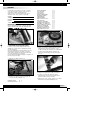
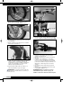
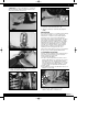
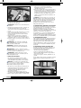
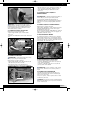
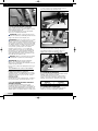
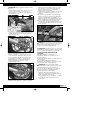
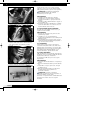
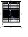

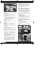
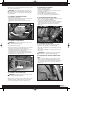
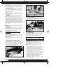
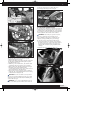
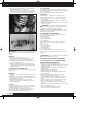
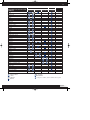
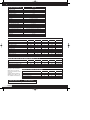
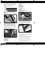
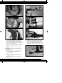
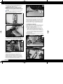
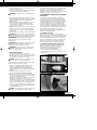
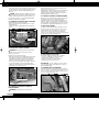
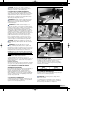
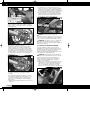
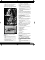
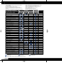
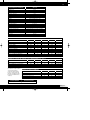
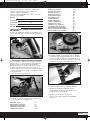
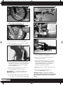
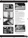
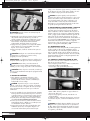
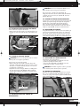
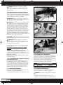
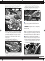
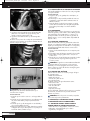
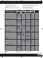
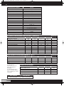
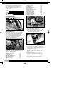
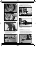


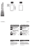

![Manuale [de]](http://vs1.manualzilla.com/store/data/006744650_1-ed92225d5e395f0fd2ab4bb1d4393f6a-150x150.png)