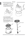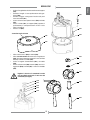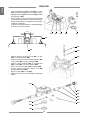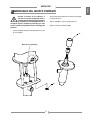
1
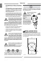
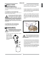
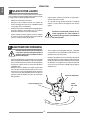
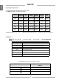
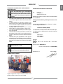
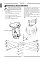
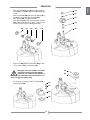
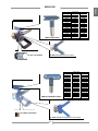
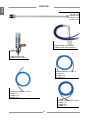
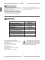
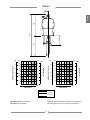
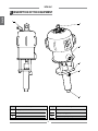
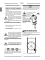
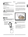
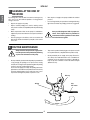
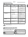
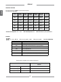
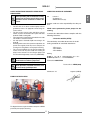
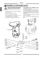
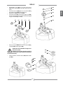
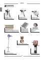
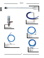
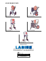
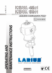
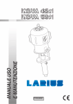
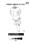
MANUALE USO
E MANUTENZIONE
II 2 G c IIB T6
ITALIANO
Ed. 006
03 - 10
NOVA 45:1/60:1
Italiano
POMPE PNEUMATICHE AIRLESS PER VERNICIATURA
N
O
P
Q
INTRODUZIONE........................................................p.1
A
B
C
D
E
F
G
H
I
L
M
PRINCIPIO DI FUNZIONAMENTO.....................p.2
Dati tecnici......................................................p.2
DESCRIZIONE DELL’APPARECCHIATURA.......p.4
DESCRIZIONE PER AREE ESPLOSIVE............p.9
SMONTAGGIO DEL MOTORE PNEUMATICO...p.12
SMONTAGGIO DEL GRUPPO POMPANTE.......p.17
ESPLOSO GRUPPO POMPANTE IN
TRASPORTO E DISIMBALLAGGIO....................p.5
ACCIAIO INOX....................................................p.20
NORME DI SICUREZZA.....................................p.5
INSTALLAZIONE TIPICA.....................................p.6
R ESPLOSO GRUPPO MOTORE..........................p.22
S ESPLOSO GRUPPO POMPANTE IN ACCIAIO
MESSA A PUNTO...............................................p.7
AL CARBONIO....................................................p.24
T
U
V
Z
FUNZIONAMENTO.............................................p.7
PULIZIA DI FINE LAVORO..................................p.8
MANUTENZIONE ORDINARIA...........................p.8
INCONVENIENTI E RIMEDI...............................p.9
Leggere attentamente
questo manuale prima di
usare l'apparecchiatura.
Un uso improprio può
causare danni a cose e
persone.
Segnala il rischio di
un infortunio o danno
grave all'apparecchiatura se non
viene seguito
l'avvertimento.
Segnala il rischio di
incendio o di esplosione se non viene
seguito
l'avvertimento.
ESPLOSO FILTRO DI LINEA ALTA PRESSIONE...p.26
CARRELLO COMPLETO....................................p.28
GRUPPO COMPLETO ARIA . ............................p.29
ACCESSORI.......................................................p.30
Segnala il rischio di
lesioni e schiacciamenti
alle dita per la presenza
di parti mobili nell'apparecchiatura
Segnalano la necessità di
utilizzare particolari accessori
come guanti, occhiali, maschere e cuffie di protezione per la
sicurezza dell'operatore.
QUESTA APPARECCHIATURA É AD USO ESCLUSIVAMENTE PROFESSIONALE.
NON É PREVISTA PER UN UTILIZZO DIVERSO DA QUELLO DESCRITTO IN QUESTO MANUALE.
Grazie per aver scelto un prodotto LARIUS s.r.l.
Unitamente all'articolo acquistato riceverete
una gamma di servizi di assistenza per consentirVi
di raggiungere i risultati desiderati,
velocemente ed in modo professionale.
1
Segnala importanti indicazioni
e consigli per lo
smaltimento o il
riciclaggio di un
prodotto nel rispetto dell'ambiente.
Italiano
NOVA 45:1/60:1
A PRINCIPIO DI FUNZIONAMENTO
La pompa NOVA 45:1 (o 60:1) è una pompa pneumatica da
utilizzare nella verniciatura alta pressione senz'aria (Airless) o
per il travaso di liquidi dove è necessario alimentare più stazioni
di utilizzo.
È essenzialmente costituita da un motore ad aria e da una struttura definita «gruppo pompaggio materiale» o più semplicemente
«gruppo pompante».
Nel motore pneumatico l'aria compressa genera il movimento
verticale alternativo del pistone motore; questo movimento
viene trasmesso tramite un asta di collegamento al pistone del
pompante materiale.
Ciò fa sì che la pompa aspiri il materiale e lo spinga verso
l'uscita.
Il rapporto 45:1 (o 60:1) sta ad indicare che la pressione di uscita
del materiale è 45 (o 60) volte la pressione dell'aria di alimentazione della pompa.
B DATI TECNICI
NOVA 45:1
NOVA 60:1
PRESSIONE ARIA DI ALIMENTAZIONE POMPA
3-7 bar (40-90 psi)
3-7 bar (40-90 psi)
PRESSIONE MASSIMA DEL PRODOTTO
270 bar (3900 psi)
360 bar (5200 psi)
3/4" GAS (M)
3/4" GAS (M)
14 l/min (3,7 gpm)
12 l/min (3,2 gpm)
NUMERO DI CICLI PER LITRO
4
5
MASSIMO N° DI CICLI AL MINUTO
60
60
1" GAS conico (F)
1" GAS conico (F)
57 kg
57 kg
<90 dB (A)
<90 dB (A)
1110 mm
1110 mm
INGRESSO ARIA DI ALIMENTAZIONE
PORTATA MASSIMA
USCITA MATERIALE
PESO
LIVELLO DELLA PRESSIONE SONORA
ALTEZZA TOTALE
Parti della pompa a contatto del materiale
Gruppo pompante: acciaio al carbonio zincato e ghisa o acciaio
inox AISI 303 e 420B
Sfere di tenuta: acciaio inox AISI 420B
Guarnizioni: teflon oppure gomma nitrile o delrin o vulkollan
Tenere ben presente queste note quando si
deve valutare la compatibilità di un prodotto
da utilizzare e quando si vuole procedere
all'eliminazione di uno o più particolari della
pompa non più utilizzabili, ai fini di programmare il riciclaggio
dei singoli componenti nel rispetto dell'ambiente.
Altri parti della pompa
Supporto e cilindro motore pneumatico: alluminio
Copertura: lamiera FE37
Pistone motore e supporto spingi rullo: ghisa
2
NOVA 45:1/60:1
Italiano
530
240
1110
580
87
150
100
4000
160
3500
140
3000
120
2500
100
2000
80
1500
60
1000
40
50
300
4000
3200
2400
1600
800
500
0
BAR
L/MIN
0
0
240
180
120
2
5
3
10
4
15
5 GPM
20
0
0
0
CFM
4800
120
4200
105
3600
90
3000
75
2400
60
1800
45
1200
30
600
15
L/MIN
60
20
1
PSI
L/MIN
2400
1800
1200
600
0
0
PORTATA POMPA
3000
CONSUMO D'ARIA
200
CFM
PRESSIONE USCITA MATERIALE
PRESSIONE USCITA MATERIALE
250
PSI
CONSUMO D'ARIA
BAR
1
2
5
3
10
4
15
5 GPM
20
0
0
L/MIN
PORTATA POMPA
7 bar (100 psi)
5 bar (70 psi)
3 bar (40 psi)
Curva nera: pressione uscita materiale
Curva grigia: consumo aria
La pompa può funzionare in continuità quando la portata è limitata
alla zona bianca. Fuori da questa zona la velocità deve essere
intermittente.
3
Italiano
NOVA 45:1/60:1
C DESCRIZIONE DELL'APPARECCHIATURA
1
6
2
5
3
4
POS.
POS.
Descrizione
Descrizione
1
Ingresso aria di alimentazione pompa
4
Entrata materiale
2
Motore pneumatico
5
Gruppo pompante materiale
3
Uscita materiale
6
Golfare per trasporto pompa
4
NOVA 45:1/60:1
Italiano
D TRASPORTO E DISIMBALLAGGIO
• Rispettare scrupolosamente l'orientamento dell'imballaggio indicato esternamente da scritte o simboli.
•
Prima di installare l'apparecchiatura, si predisponga un
ambiente idoneo con lo spazio necessario, la corretta
illuminazione, la pavimentazione pulita e liscia.
IL COMPORTAMENTO DEL PERSONALE D OVRÀ
RISPETTARE SCRUPOLOSAMENTE LE NORME ANTINFORTUNISTICHE DEL PAESE IN CUI È INSTALLATA
L'APPARECCHIATURA OLTRE CHE LE NORME IN MATERIA
DI INQUINAMENTO AMBIENTALE
Leggere attentamente ed integralmente le seguenti istruzioni prima di utilizzare il prodotto.
Custodire con cura le istruzioni.
• Tutte le operazioni di scarico e movimentazione dell'apparecchiatura sono di pertinenza dell'utilizzatore che dovrà
fare molta attenzione per evitare di provocare danni alle
persone o all'apparecchiatura.
Per l'operazione di scarico si utilizzi del personale specializzato ed abilitato (carrellisti, gruisti ecc.) ed un mezzo di
sollevamento idoneo che abbia portata adeguata al peso
dell'imballo e si rispettino tutte le norme di sicurezza.
Il personale dovrà essere dotato delle necessarie protezioni individuali.
La manomissione o la sostituzione non autorizzata di una o più parti che compongono
l'apparecchiatura, l'uso di accessori, di utensili,
di materiali di consumo diversi da quelli raccomandati dal costruttore, possono rappresentare pericolo di
infortunio e sollevano il costruttore da responsabilità civili
e penali.
•
TENERE IN ORDINE L'AREA DI LAVORO. DISORDINE
SUL POSTO DI LAVORO COMPORTA PERICOLO DI
INCIDENTI.
•
MANTENERE SEMPRE UN BUON EQUILIBRIO EVITANDO
POSIZIONI MALSICURE.
• Verificare l'integrità dell'imballo all'atto del ricevimento.
Togliere l'apparecchiatura dall'imballo e controllare che
non abbia subito danni durante il trasporto.
Qualora si riscontrassero componenti danneggiati,
contattare tempestivamente la LARIUS e l'Agente di
trasporto. Il termine massimo per le comunicazioni di
danneggiamento è di 8 giorni dalla data di ricevimento
dell'apparecchiatura.
La comunicazione dovrà avvenire tramite raccomandata
con ricevuta di ritorno indirizzata alla LARIUS ed al
trasportatore.
•
PRIMA DELL'UTILIZZO CONTROLLARE SCRUPOLOSAMENTE CHE NON VI SIANO PARTI DANNEGGIATE E CHE
L'APPARECCHIATURA SIA IN GRADO DI EFFETTUARE IL
SUO LAVORO IN MODO CORRETTO.
•
OSSERVARE SEMPRE LE ISTRUZIONI PER LA SICUREZZA E LE NORMATIVE VIGENTI.
•
NON PERMETTERE CHE PERSONE ESTRANEE POSSANO ACCEDERE ALL’AREA DI LAVORO.
•
NON SUPERARE MAI LE PRESSIONI MASSIME DI ESERCIZIO INDICATE.
• Lo smaltimento dei materiali di imballaggio, a carico dell'utilizzatore, dovrà essere eseguito in conformità alle normative
vigenti nel paese di utilizzo dell'apparecchiatura.
É comunque buon comportamento riciclare il più possibile
in modo ecologico i materiali dell'imballaggio.
•
NON DIRIGERE MAI LA PISTOLA VERSO SE STESSI O
ALTRE PERSONE. IL CONTATTO CON IL GETTO PUÒ
CAUSARE SERIE FERITE.
•
IN CASO DI FERITE PROCURATE DAL GETTO DELLA
PISTOLA RICORRERE SUBITO ALLE CURE DI UN MEDICO SPECIFICANDO IL TIPO DI PRODOTTO INIETTATO.
NON SOTTOVALUTARE MAI UNA LESIONE PROCURATA
DALL’INIEZIONE DI UN FLUIDO.
•
TOGLIERE SEMPRE L’ALIMENTAZIONE ELETTRICA E
SCARICARE LA PRESSIONE NEL CIRCUITO PRIMA DI
EFFETTUARE QUALSIASI TIPO DI CONTROLLO O DI
SOSTITUZIONE DEI PARTICOLARI DELL’APPAREC-CHIATURA.
•
NON MODIFICARE MAI NESSUN PARTICOLARE DELL’APPARECCHIATURA. VERIFICA REGOLARMENTE I
COMPONENTI DEL SISTEMA.SOSTITUIRE I PARTICOLARI
DANNEGGIATI O USURATI.
•
STRINGERE E CONTROLLARE TUTTI I RACCORDI DI
• Il costruttore declina ogni responsabilità relativa allo scarico
ed al trasporto dell'apparecchiatura sul luogo di lavoro.
E NORME DI SICUREZZA
•
IL DATORE DI LAVORO DOVRÀ PROVVEDERE AD
ISTRUIRE IL PERSONALE SUI RISCHI DI INFORTUNI,
SUI DISPOSITIVI DI SICUREZZA DELL'OPERATORE E
SULLE REGOLE ANTINFORTUNISTICHE GENERALI
PREVISTE DALLE DIRETTIVE INTERNAZIONALI E
DELLA LEGISLAZIONE DEL PAESE IN CUI È INSTALLATA L'APPARECCHIATURA OLTRE CHE LE NORME
IN MATERIA DI INQUINAMENTO AMBIENTALE.
5
Italiano
NOVA 45:1/60:1
COLLEGAMENTO TRA LA POMPA, IL TUBO FLESSIBILE
E LA PISTOLA PRIMA DI UTILIZZARE L’APPARECCHIATURA.
•
UTILIZZARE SEMPRE IL TUBO FLESSIBILE PREVISTO
NEL CORREDO STANDARD DI LAVORO. L'IMPIEGO DI
ACCESSORI O ATTREZZATURA DIVERSI DA QUELLI
RACCOMANDATI NEL PRESENTE MANUALE PUÒ ESSERE CAUSA DI INFORTUNI.
•
PRENDERE APPROPRIATE MISURE DI PROTEZIONE
DELL’UDITO SE SI LAVORA NELLE IMMEDIATE VICINANZE
DELL’APPARECCHIATURA.
Dopo alcuni minuti di funzionamento, la superficie
metallica superiore dell’apparecchiatura
raggiunge una temperatura
molto bassa.
Evitare di toccare la zona
indicata.
Il contatto della pelle con la
zona a bassa temperatura
può causare congelamento.
Indumenti comuni di lavoro e
guanti (di cuoio) forniscono
una protezione adeguata.
IL FLUIDO CONTENUTO NEL TUBO FLESSIBILE PUÒ ESSERE MOLTO PERICOLOSO. MANEGGIARE CON CURA IL
TUBO FLESSIBILE. NON TIRARE IL TUBO FLESSIBILE PER
SPOSTARE L’APPARECCHIATURA. NON UTILIZZARE MAI
UN TUBO FLESSIBILE DANNEGGIATO O RIPARATO.
L’elevata velocità di scorrimento del prodotto
nel tubo flessibile può creare elettricità statica
che si manifesta con piccole scariche e scintille.
Si raccomanda di collegare a terra l’apparecchiatura. La pompa e’ collegata a terra dal filo
di massa del cavo dell’alimentazione elettrica. La pistola e’
collegata a terra mediante il tubo alta pressione flessibile.
Tutti gli oggetti conduttori che si trovano in prossimità della
zona di lavoro devono essere collegati a terra.
•
EVITARE ASSOLUTAMENTE DI SPRUZZARE PRODOTTI
INFIAMMABILI O SOLVENTI IN AMBIENTI CHIUSI.
•
EVITARE ASSOLUTAMENTE DI UTILIZZARE L’APPARECCHIATURA IN AMBIENTI SATURI DI GAS POTENZIALMENTE ESPLOSIVI.
F INSTALLAZIONE TIPICA
La pompa NOVA viene solitamente fornita già fissata su staffa per
il fissaggio a parete oppure su carrello o su paranco pneumatico.
Per il corretto fissaggio della pompa su altre strutture utilizzare
i 4 fori posti sulla base del motore pneumatico (vedi figura per
quote dimensionali).
Verificare sempre la compatibilità del prodotto
con i materiali che compongono l’apparecchiatura (pompa, pistola, tubo flessibile e
accessori) con i quali può venire a contatto.
Non utilizzare vernici o solventi che contengono
idrocarburi alogenati (come il cloruro di metilene). Questi
prodotti a contatto con parti in alluminio dell’apparecchiatura
possono causare pericolose reazioni chimiche con rischio
di esplosione.
Ø266 *
45°
45°
Evitare di avvicinarsi eccessivamente allo
stelo pistone della pompa quando questa è in
funzione o in pressione.
Un movimento improvviso o brusco dello stelo
pistone può provocare lesioni o schaicciamenti alle dita.
Ø11
SE IL PRODOTTO DA UTILIZZARE E’ TOSSICO EVITARE L’INALAZIONE E IL CONTATTO UTILIZZANDO GUANTI PROTETTIVI,
OCCHIALI DI PROTEZIONE E APPROPRIATE MASCHERE.
Ø240
*Int. fori
6
NOVA 45:1/60:1
• Far affluire l'aria compressa alla pompa. Si consiglia di regolare
la pressione dell'aria al valore minimo che è necessario al
funzionamento della stessa in modo continuativo.
FISSAGGIO DELLA POMPA SUL PARANCO
Per il corretto fissaggio della pompa sul paranco seguire la procedura descritta nel manuale uso e manutenzione del paranco
pneumatico.
• La pompa si metterà in funzione e si arresterà quando tutta
la camera del prodotto sarà piena. La pompa ricomincerà
a funzionare ogni volta che verrà premuto il grilletto della
pistola o aperta la valvola erogatrice.
COLLEGAMENTO ALL'ARIA DI ALIMENTAZIONE
Per l'alimentazione della pompa utilizzare un tubo avente un
diametro interno non inferiore a 20 mm.
• La pompa è stata collaudata in fabbrica con olio minerale
leggero che può essere rimasto in parte all'interno del pompante. Puntare la pistola (H3) o la valvola erogatrice contro
un recipiente di raccolta (H4) ed espellere il prodotto rimasto
nella pompa fino a che non si veda uscire il materiale da
utilizzare.
Installare all'ingresso della pompa un regolatore
di pressione dell'aria (si consiglia completo di
filtro condensa e lubrificatore). La pressione
di uscita del materiale è 45 volte (NOVA 45:1)
o 60 volte (NOVA 60:1) la pressione d'ingresso dell'aria di
alimentazione della pompa. Quindi è di fondamentale importanza poter regolare il valore della pressione dell'aria di
alimentazione.
H3
H4
COLLEGAMENTO DEL TUBO USCITA MATERIALE
Collegare il tubo alta pressione all'uscita della pompa.
Si raccomanda di serrare fortemente i raccordi.
H fUNZIONAMENTO
Controllare tutti i raccordi di collegamento dei diversi componenti (pompa, tubo flessibile, pistola,
ecc.) prima di utilizzare l'apparecchiatura.
• Immergere il tubo pompante materiale (H1) nel serbatoio
del prodotto (H2) (se
la pompa è fissata sul
paranco pneumatico
seguire la procedura
descritta nel manuale
uso e manutenzione del
pneumatico).
Evitare assolutamente di far funzionare la pompa
a vuoto: questo potrebbe provocare seri danni
al motore pneumatico e rovinare le guarnizioni
di tenuta.
• Se si prevedono delle lunghe pause durante l'utilizzo dell'apparecchio (ad esempio la pausa notturna alla fine della giornata
lavorativa), accertarsi che il prodotto che si sta utilizzando può
essere lasciato all'interno della pompa e delle varie tubature
senza pericolo che secchi.
Se questo rischio non sussiste, allora in caso di pausa lavorativa è sufficiente interrompere la fornitura di aria alla pompa
e scaricare la pressione nel circuito agendo sulla valvola
erogatrice oppure sulla valvola di spurgo della pompa.
H1
H2
7
Italiano
G MESSA A PUNTO
Italiano
NOVA 45:1/60:1
I PULIZIA DI FINE LAVORO
Per pulizia di fine lavoro si intende la pulizia da effettuare qualora
si volesse utilizzare un diverso prodotto oppure quando si prevede
un lungo periodo di inattività dell'apparecchiatura.
•
Chiudere la fornitura d'aria alla pompa.
•
Immergere il tubo pompante materiale nel serbatoio del
solvente di lavaggio (accertare la sua compatibilità chimica
con il prodotto che si sta utilizzando).
•
Far affluire l'aria compressa alla pompa. Si consiglia di regolare
la pressione dell'aria al valore minimo che è necessario al
funzionamento della stessa in modo continuativo.
•
•
A questo punto, chiudere la fornitura di aria alla pompa e
scaricare la pressione residua.
•
Se si prevede un lungo periodo di inattività si consiglia di
aspirare e lasciare all'interno del pompante olio minerale
leggero.
Conservare eventuali fluidi pericolosi in contenitori appropriati. Essi vanno eliminati in
osservanza alle leggi relative allo smaltimento
dei rifiuti industriali.
Puntare la pistola o la valvola erogatrice contro un recipiente
di raccolta ed espellere il prodotto rimasto nella pompa fino
a che non si veda uscire del solvente pulito.
L MANUTENZIONE ORDINARIA
Chiudere sempre la fornitura di aria compressa
e scaricare la pressione nell'impianto prima di
effettuare qualsiasi tipo di controllo o di manutenzione sulla pompa.
•
Verificare periodicamente (e ogni volta che si avvia la pompa
dopo un lungo periodo di inattività) che la ghiera premi guarnizioni non sia allentata provocando la fuoriuscita del prodotto.
Per stringere la ghiera sollevare la tazza porta lubrificante
(vedi figura sotto).
Utilizzare la chiave in dotazione (rif. 11504). La ghiera deve
essere stretta in modo da impedire perdite ma non eccessivamente per non causare il grippaggio del pistone pompante
e l'usura eccessiva delle guarnizioni di tenuta. Se dovesse
persistere perdita di prodotto procedere alla sostituzione
delle guarnizioni.
•
Tenere riempita la tazza di liquido lubrificante (compatibile
con il prodotto che si sta utilizzando) in modo da evitare che
il prodotto secchi sullo stelo pistone.
•
Controllare periodicamente la linea di fornitura dell'aria alla
pompa. Accertarsi che l'aria sia sempre ben pulita e lubrificata.
Se sulla linea di fornitura dell'aria alla pompa è stato installato
un lubrificatore si consiglia di tenere riempita la tazza dello
stesso di una miscela di acqua e liquido antigelo (rapporto
di diluzione 4:1).
Tazza porta lubrificante
Corona di rabbocco olio
Chiave
Rif. 11504
8
NOVA 45:1/60:1
Italiano
M INCONVENIENTI E RIMEDI
Causa
Soluzione
• L'aria di alimentazione è insufficiente;
• Controllare la linea di fornitura
dell'aria. Aumentare il diametro del
tubo di alimentazione;
• Pulire. Staccare il tubo di uscita del
prodotto. Alimentare la pompa al
minimo della pressione e verificare
se senza il tubo di uscita la pompa
parte;
• Smontare il gruppo pompante e
pulire;
• Svitare il tappo e spingere in giù
il corpo valvola. Utilizzare un'asta
metallica e una mazzuola;
• Smontare il motore e verificare;
Problema
•
La pompa non entra in funzione
• Linea di uscita del prodotto intasata;
•
•
La pompa ha un funzionamento
accelerato e non va in pressione
•
Prodotto seccato all'interno del pompante;
Motore pneumatico bloccato nella
posizione di inversione ciclo;
•
Rottura di particolari del motore pneumatico;
• Manca il prodotto;
• La pompa aspira aria;
•
•
La pompa funziona ma c'è insufficiente uscita di prodotto
•
L'aria di alimentazione è insufficiente;
Valvola di aspirazione usurata o parzialmente ostruita;
•
Valvola di uscita prodotto usurata o
parzialmente ostruita;
• Valvola di aspirazione usurata o parzialmente ostruita;
• Linea di uscita del prodotto intasata;
• La pressione dell'aria di alimentazione
è troppo bassa;
•
Perdita di prodotto della tazza
porta lubrificante
•
Guarnizioni superiori usurate.
• Aggiungere il prodotto;
• Aprire la valvola di spurgo. Per la versione sul paranco vedere le istruzioni
contenute nel manuale relativo;
• Aumentare la pressione dell'aria di
alimentazione;
• Smontare la valvola di aspirazione.
Pulire e/o eventualmente sostituire
i particolari usurati;
• Smontare la valvola di uscita. Pulire
e/o eventualmente sostituire i particolari usurati;
• Smontare la valvola di aspirazione.
Pulire e/o eventualmente sostituire
i particolari usurati;
• Pulire. Staccare il tubo di uscita del
prodotto, alimentar e la pompa al
minimo della pressione e verificare
se senza il tubo di uscita la portata
aumenta;
• Aumentare la pressione dell'aria;
•
Stringere la ghiera premi guarnizioni.
Se persiste perdita di prodotto sostituire le guarnizioni superiori del
pompante.
Chiudere sempre la fornitura di aria compressa e scaricare la pressione nell'impianto prima di effettuare qualsiasi
tipo di controllo o sostituzione dei particolari della pompa.
N DESCRIZIONE PER AREE ESPLOSIVE
Queste istruzioni di sicurezza si riferiscono all’installazione, uso
e manutenzione delle pompe pneumatiche a pistone per travaso
LARIUS serie NOVA per l’utilizzo in aree potenzialmente esplosive
con presenza di gas o vapori.
Le pompe pneumatiche a pistone LARIUS serie
NOVA sono apparecchiature meccaniche del
gruppo II, per l'uso in zone classiche con presenza
di gas IIB (categoria 2G). Esse sono progettate e
costruite in accordo alla direttiva ATEX 94/9/CE,
secondo le norme europee: EN 1127-1, EN 13463-1
ed EN 13463-5.
Queste istruzioni devono essere osservate in
aggiunta alle avvertenze riportate nel manuale
d’uso e manutenzione.
9
CARATTERISTICHE TECNICHE
Le principali caratteristiche delle pompe pneumatiche a pistone
serie NOVA sono indicate nella tabella sotto riportata:
Rapporto
Pressione
Ø Ingresso
alimentazione
aria
Ø Ingresso
materiale
Ø Uscita
materiale
Pressione di
lavoro max
Portata
max
20:1
3 ÷ 6 bar
CG 3/4"
Valvola sfera CG 1. 1/2"
120 bar
32 l/min
45:1
3 ÷ 6 bar
CG 3/4"
Valvola sfera CG 1. 1/2"
270 bar
14 l/min
55:1
3 ÷ 6 bar
CG 3/4"
Piattello
CG 1"
330 bar
12 l/min
60:1
3 ÷ 6 bar
CG 3/4"
Valvola sfera
CG 1"
360 bar
12 l/min
68:1
3 ÷ 6 bar
CG 3/4"
Valvola sfera
CG 3/4"
410 bar
11 l/min
• Temperatura ambiente: -20°C ÷ +60°C
• Temperatura massima del fluido: 60°C
• Numero massimo di cicli al minuto: 60
MARCATURA
3
Italiano
NOVA 45:1/60:1
X
II 2 G c IIB T6
• Tamb: -20°C ÷ + 60°C
• Tmax. fluido: 60°C
• Tech. File: NOVA/ATX/08
II =
Gruppo II ( superficie)
2=
Categoria 2 (zona 1)
G=
Atmosfera esplosiva con presenza di gas, vapori o nebbie
c=
Sicurezza costruttiva "c"
T6 =
Classe di temperatura T6
- 20°C ÷ + 60°C
60°C
Temperatura ambiente
Massima temperatura del fluido di processo
xxxx/AA
Numero di serie o numero di lotto (xxxx = PROGRESSIVO/ anno = AA)
Corrispondenze tra zone pericolose, sostanze e categorie
ZONA PERICOLOSA
CATEGORIE SECONDO DIRETTIVA
94/9/CE
Gas, vapori o nebbie
Zona 0
1G
Gas, vapori o nebbie
Zona 1
2G oppure 1G
Gas, vapori o nebbie
Zona 2
3G, 2G oppure 1G
10
NOVA 45:1/60:1
ESEMPIO DI DICHIARAZIONE DI CONFORMITÀ
Prima dell’installazione leggere attentamente
quanto riportato nel manuale d’uso e manutenzione. Tutte le operazioni di manutenzione devono
essere eseguite secondo quanto riportato nel
manuale.
•
•
•
•
•
Larius S.r.l.
Via Stoppani, 21
23801 Calolziocorte (LC)
dichiariamo sotto la nostra esclusiva responsabilità
che il prodotto:
Il cavo di M.T. delle suddette pompe deve essere collegato
a terra mediante apposito elemento di connessione antiallentante.
Le tubazioni utilizzate per il collegamento mandata e aspirazione devono essere metalliche, oppure tubazioni plastici
con treccia metallica o tubazioni in plastica con treccia tessile
con idoneo conduttore di messa a terra.
Le pompe devono essere installate su fusti in materiale
metallico oppure in materiale antistatico, collegati a terra.
I gas o vapori dei liquidi infiammabili presenti devono appartenere al gruppo IIB.
L’utilizzatore deve controllare periodicamente, in funzione del
tipo di utilizzo e delle sostanze, la presenza di incrostazioni,
la pulizia, lo stato di usura ed il corretto funzionamento della
pompa.
L’utilizzatore deve pulire periodicamente il filtro presente
sull'aspirazione per impedire l’ingresso di corpi solidi all’interno della pompa. L’aria utilizzata per fornire potenza alla
pompa deve essere filtrata e provenire da zona sicura (SAFE
AREA).
Pompe pneumatiche a pistone per travaso serie
NOVA
al quale questa dichiarazione si riferisce è conforme alla seguente direttiva:
- Directive 94/9/EC (ATEX)
La conformità è stata verificata sulla base dei requisiti delle norme o dei documenti normativi riportati
nel seguito:
- EN 1127-1
- EN 13463-1
- EN 13463-5
Marcatura
3
•
Noi
X
II 2 G c IIB T6 • Tamb: -20°C ÷ + 60°C • Tmax. fluido: 60°C
Fascicolo tecnico: NOVA/ATX /08
Le pompe pneumatiche a pistone serie NOVA non
devono funzionare a vuoto.
Fascicolo tecnico depositato c/o: INERIS (0080)
Tutte le operazioni di installazione e manutenzione
devono essere fatte da personale qualificato.
Calolziocorte- LC
ESEMPIO DI INSTALLAZIONE
In figura è rappresentato un tipico esempio di installazione di una
pompa pneumatica a pistone per travaso LARIUS.
11
Firma (LARIUS)
Italiano
ISTRUZIONE DI SICUREZZA PER L'INSTALLAZIONE IN
ZONA PERICOLOSA
Italiano
NOVA 45:1/60:1
O SMONTAGGIO DEL MOTORE PNEUMATICO
Chiudere sempre la fornitura di aria compressa
e scaricare la pressione prima di procedere
allo smontaggio del motore pneumatico della
pompa.
•
Svitare il manicotto di giunzione così da staccare il gruppo
pompante dal motore.
•
Staccare il tubo di alimentazione dell'aria alla pompa.
•
Svitare il raccordo (N1) e il manicotto (N2).
•
Svitare le viti (N3) [fare attenzione alle rondelle (N4)] e togliere
la copertura (N5).
•
Svitare le due ghiere (N6) dal supporto (N7).
•
Svitare le viti (N8) [attenzione alle rondelle (N9)] e sfilare il
supporto (N7) assieme ai rulli (N10) e alle spine (N11).
•
Sfilare la molla (N12), l'asta guida molla (N13) e il pistone
spingi rullo (N14). Accertarsi che la molla scorra liberamente
sull'asta di guida, che l'asta di guida scorra liberamente nel
pistone spingi rullo e che quest'ultimo scorra liberamente
all'interno del foro del supporto.
•
Verificare l'integrità del rullo (N10) e della spina (N11). Sostituirli se danneggiati.
•
Togliere e controllare l'ammortizzatore (N15) e la rondella
(N16).
N1
N2
N3
N4
N5
Manicotto di congiunzione
N8
N9
N7
N14
N13
N6
N12
N12
N13
N6
N14
N10
N10
N11
N11
N15
N16
12
NOVA 45:1/60:1
•
•
•
Tirare verso l'alto l'alloggiamento (N17) così da poter togliere le
valvole (N18) e le molle (N19) (pulire e/o sostituire i particolari
usurati).
Svitare il controdado (N20) [attenzione alla rondella (N21)]
tenendo bloccata con una chiave la bussola (N22).
Sfilare dall'asta (N23) l'alloggiamento (N17).
Svitare la bussola (N22) (se necessario, tenere bloccata l'asta
(N23) sulla parte filettata con una pinza i cui becchi siano
avvolti in uno straccio per non danneggiare il filetto).
N18
•
N19
N17
N19
N20
N21
N17
N22
N23
N18
Togliere le viti (N24) [attenzione alle rondelle (N25)] e rimuovere un collettore (N26) e la guarnizione (N27).
Maneggiare con cura il collettore. I bordi della
piastra ad esso fissata sono molto taglienti.
Importante: non rimuovere l'altro collettore se
non strettamente necessario (faciliterà il successivo fissaggio del collettore tolto).
•
N28
N29
Con l'aiuto di un cacciavite estrarre la rondella (N28) e
l'ammortizzatore (N29).
N24
N25
N26
N27
13
Italiano
•
Italiano
NOVA 45:1/60:1
•
•
Svitare la vite guida asta (N30) [attenzione alla rondella (N31)]
e verificare che la guarnizione di tenuta all'interno della vite
(N30) non sia rovinata.
Togliere le viti (N32) [attenzione alle rondelle (N33) ] e rimuovere con cura il cilindro (N34) (evitare di inclinarlo eccessivamente mentre lo si sfila onde evitare che il pistone motore
possa danneggiare la superficie interna del cilindro).
N32
N30
N33
N34
N31
•
•
•
•
•
•
Sfilare il pistone dal supporto motore (N35).
Verificare l'integrità dell'anello OR (N36).
Stringere con una pinza il bordo inferiore dello stelo pistone
(vedi figura) e con una chiave svitare il raccordo (N37).
Togliere l'asta motore (N38) e verificare che non sia danneggiata.
Spalmare del grasso di vaselina sull'asta motore (N38) prima
di inserirla nella cavità dello stelo pistone.
Stringere con una pinza ancora il bordo inferiore dello stelo
pistone e avvitare il raccordo (N37) (si consiglia di applicare
sul filetto un liquido sigillante).
Attenzione: stringere qui
N36
N38
N35
N37
14
NOVA 45:1/60:1
•
•
•
•
•
Italiano
•
Verificare l'integrità dell'anello di tenuta all'interno del supporto
(N39).
Controllare l'integrità e l'esatto posizionamento della guarnizione (N40).
Stendere un leggero velo di grasso di vaselina sulle pareti
interne del cilindro (N41).
Inserire con molta cautela il pistone motore (N42) nel cilindro
(N41).
Fissare il cilindro (N41) sul supporto (N39) (rispettare il
posizionamento) e contemporaneamente inserire lo stelo
motore nel supporto.
Avvitare le viti (N43).
N43
N41
Controllare l'anello di tenuta
N40
N42
N39
•
•
Infilare sull'asta motore (N44) la rondella (N45).
Infilare con molta cautela sull'asta motore la vite guida asta
(N46) (farla girare lentamente seguendo il senso del filetto
dell'asta) e avvitarla sul cilindro (N41).
Inserire nel supporto l'ammortizzatore (N47) e la rondella
(N48).
Avvitare sull'asta motore (N44) la bussola (N49), inserire l'alloggiamento (N50), la rondella (N51) e avvitare il controdado
(N52).
N52
N51
N50
Regolare la bussola e il controdado in modo
che l'asta (N44) spunti fuori di 1 mm circa dal
controdado (vedi figura).
N48
1 mm
•
•
N49
N47
N46
N45
N44
N44
15
Italiano
NOVA 45:1/60:1
•
•
Inserire nell'alloggiamento (N53) le molle (N54) e le valvole
(N55), posizionare l'alloggiamento sul supporto pompa e
appoggiare contro l'alloggiamento il collettore (N56) [ricordarsi
della guarnizione (N57)].
Fissare il collettore con le viti (non stringere eccessivamente
per il momento) assicurandosi che esso risulti perfettamente
parallelo all'altro collettore e che la distanza tra i due collettori
sia di 46 mm (vedi figura).
La distanza tra le pareti del collettore e il bordo dell'alloggiamento deve essere di circa 0,8 mm.
46 mm
0,8 mm
N53
0,8 mm
N54
N55
N56
N57
N56
N68
N53
•
•
•
•
•
•
•
N67
Spalmare del grasso di vaselina sui rulli (N58) e le spine
(N59) e inserirli nel supporto (N60).
Spalmare del grasso di vaselina sull'ammortizzatore (N61)
e sulla rondella (N62) e inserirli nel supporto (N60).
Ingrassare i pistoni spingi rullo (N63), le aste guida molla
(N64), le molle (N65) e inserirli nel supporto (N60).
Fissare senza avvitare le ghiere (N66) al supporto (N60).
Fissare il supporto sui collettori e stringere le viti (N68)
[ricordarsi delle rondelle (N67)].
Stringere le ghiere (N66) e le viti (N69).
Rimontare la copertura e i vari raccordi della linea di fornitura
dell'aria.
N66
N69
N60
N66
N65
N64
N63
N58
N59
N61
N62
16
NOVA 45:1/60:1
Italiano
P SMONTAGGIO DEL GRUPPO POMPANTE
Chiudere la fornitura di aria compressa e
scaricare la pressione nell'impianto prima di
procedere allo smontaggio del gruppo pompante.
Se il prodotto che si sta utilizzando è tossico si
consiglia di seguire la procedura di pulizia di pag. 8, onde
evitare il contatto con il prodotto durante lo smontaggio del
pompante.
•
•
Svitare il manicotto di congiunzione così da staccare il gruppo
pompante dal motore.
•
Togliere i dadi (O1) e staccare il gruppo pompante.
•
Togliere la tazza porta lubrificante (O2).
Staccare dal gruppo pompante il tubo di aspirazione e il tubo
di uscita prodotto.
O2
Manicotto di congiunzione
O1
17
Italiano
NOVA 45:1/60:1
•
Togliere la copiglia (O3), allentare il dado (O4) e svitare il
tirante di congiunzione dallo stelo pistone.
•
Svitare la ghiera premi guarnizione (O5).
O5
Tirante di congiunzione
O4
O3
•
Svitare la valvola di aspirazione. Pulire e/o sostituire se
necessario i particolari della stessa.
18
NOVA 45:1/60:1
Italiano
Si può aumentare la corsa della sfera della
valvola di aspirazione posizionando la spina
fermo sfera (O6) nei fori superiori della valvola
di aspirazione. Questa modifica è consigliata
in presenza di prodotti da aspirare molto viscosi. La stessa
modifica può essere effettuata sullo stelo pistone.
O6
O6
Valvola di aspirazione
•
•
•
•
Sfilare dal basso lo stelo pistone.
Smontare lo stelo pistone e sostituire le guarnizioni usurate.
Togliere se necessario le guarnizioni superiori per la loro
sostituzione.
Per il riassemblaggio corretto vedere figura e esploso a pag.
18.
19
Italiano
NOVA 45:1/60:1
Q ESPLOSO GRUPPO POMPANTE IN ACCIAIO INOX
ATTENZIONE : per ogni particolare richiesto indicare sempre il codice e la quantità.
20
1
2
11
3
12
10
9
9A
9
9A
9
4
5
8
21
22
23
6
7
13
7A
7B
7C
24
25
14
8
9
9A
26
27
2
16
9
9A
28
19
17
9
30
18
10
15
29
20
NOVA 45:1/60:1
Italiano
Pos.
Codice
Descrizione
Pos.
Codice
,
1
2*
3
4
5
6
7
7A
7B
7C
8*
9*
9A*
10*
11
12
98200
,
95003
95015
95004
95005
95006
95007
95008
95008/1
95008/3
95008/2
98209
95010
95138
98212
98214
98126
Gruppo pompante completo per
NOVA 45:1 inox
Bussola
Copiglia
Manicotto
Anello OR
Tirante
Dado
Tazza completa di ghiera
Tazza
Anello OR
Ghiera premiguarnizioni
Anello femmina
Guarnizione a "V" in teflon
Guarnizione polietilene
Anello maschio
Alloggiamento pompante
Raccordo per filtro
13
14
15
16
17
18*
19
20
21
22
23
24
25
26*
27
28
29
30
95016
98217
96099
98218
98220
98219
98053
98222
98223
98224
98225
98226
95027
95028
98229
98230
98232
98231
Descrizione
Guarnizione
Camicia
Bussola
Stelo pistone
Spina fermo sfera
Anello elastico
Sfera Ø7/8"
Anello premiguarnizione
Valvola pistone
Anello
Spina fermo sfera
Guida sfera
Sfera Ø1-1/4"
Anello OR
Valvola di aspirazione
Riduzione M-F
Raccordo tubo di aspirazione
Gomito M-F 1" GAS"
*Kit riparazione pompante NOVA 45:1 in acciaio inox Rif. 40071
Pos.
Codice
Descrizione
Pos.
Codice
,
1
2*
3
4
5
6
7
7A
7B
7C
8*
9*
9A*
10*
11
12
98201
,
95003
95015
95004
95005
95006
95007
95502
95008/1
95008/3
95502/1
98203
95504
95514
98204
98210
98126
Gruppo pompante completo per
NOVA 60:1 inox
Bussola
Copiglia
Manicotto
Anello OR
Tirante
Dado
Tazza completa di ghiera
Tazza
Anello OR
Ghiera premiguarnizioni
Anello femmina
Guarnizione a "V" in teflon
Guarnizione polietilene
Anello maschio
Alloggiamento pompante
Raccordo per filtro
13
14
15
16
17
18*
19
20
21
22
23
24
25
26*
27
28
29
30
95016
98208
96099
98202
98205
98219
98053
98206
98207
98224
98225
98226
95027
95028
98229
98230
98232
98231
*Kit riparazione pompante NOVA 60:1 in acciaio inox Rif. 40076
21
Descrizione
Guarnizione
Camicia
Bussola
Stelo pistone
Spina fermo sfera
Anello elastico
Sfera Ø7/8"
Anello premiguarnizione
Valvola pistone
Anello
Spina fermo sfera
Guida sfera
Sfera Ø1-1/4"
Anello OR
Valvola di aspirazione
Riduzione M-F
Raccordo tubo di aspirazione
Gomito M-F 1" GAS"
Italiano
NOVA 45:1/60:1
R ESPLOSO GRUPPO MOTORE
ATTENZIONE : per ogni particolare richiesto indicare sempre il codice e la quantità.
1
2
3
40
41
6
50
34
51
34
4
5
10
11
12
13
35
36
7
14
15
16
17
37
42
29
30
43
44
28
27
38
26
25
24
18
15
14
19
20
21
22
39
45
46A
46B
46
47
48
49
52
54
53
22
8
9
23
24
25
26
27
28
33
32
31
29
30
NOVA 45:1/60:1
Codice
Pos.
Codice
1
95062
Vite
29
95070
Collettore
2
95063
Rondella
30*
95072
Guarnizione collettore
3
95064
Copertura
31
95096
Rondella
4
95065
Vite
32
95068
Vite
5
95066
Rondella
33
95067
Tappo 3/4" GAS conico
6
95061
Golfare
34
95090
Raccordo
7
95109
Supporto
35
95089
Gomito 3/4" GAS
8
95092
Rullo
36
95088
Prolunga
9
95091
Spina
37
95099
Anello di tenuta
10
95084
Pistone spingi rullo
38
95074
Vite
11
95085
Guida molla
39
95100
Cilindro motore
12
95086
Molla
40*
95101
Anello OR
13
95087
Ghiera
41
95102
Pistone motore
14
95093
Ammortizzatore
42
95103
Asta motore
15
95094
Rondella
43
95104
Raccordo
16
95095
Controdado
44
95105
Guarnizione
17
95096
Rondella
45
95106
Anello OR
18
95098
Bussola
46
95107
Supporto motore completo
19
95078
Vite guida asta
46A*
3314
Anello di tenuta
20*
95079
Anello in cuoio
46B*
95082
Anello cuoio
21*
95080
Guarnizione di tenuta
47
95114
Rondella
22*
33031
Rondella in rame
48
95083
Vite
23
95097
Alloggiamento valvola
49
95159
Tappo
24
95077
Molla
50
510040
Tappo
25*
95075
Anello OR
51
95944
Manicotto 3/4" GAS
26
95076
Valvola inversione corsa
52
95002
Tirante
27
95073
Piastra su collettore
53
95013
Dado
28
95071
Guarnizione su piastra
54
95229
Tappo
Descrizione
*Kit guarnizioni motore pompa NOVA Rif. 40065
23
Descrizione
Italiano
Pos.
Italiano
NOVA 45:1/60:1
S ESPLOSO GRUPPO POMPANTE IN ACCIAIO AL CARBONIO
ATTENZIONE : per ogni particolare richiesto indicare sempre il codice e la quantità.
1
2
20
11
10
12
9
9
9
9
15
3
4
5
8
21
6
7A
7
7B
22
13
23
14
24
25
26
7C
8
15
9
9
9
9
2
27
16
30
28
31
17
19
18
10
24
29
NOVA 45:1/60:1
Italiano
Pos.
Codice
,
1
2*
3
4
5
6
7
7A
7B
7C
8*
9*
10*
11
12
13
95001
,
95003
95015
95004
95005
95006
95007
95008
95008/1
95008/3
95008/2
98209
95011
98212
95014
95126
95016
Descrizione
Gruppo pompante completo
per NOVA 45:1
Bussola
Copiglia
Manicotto
Anello OR
Tirante
Dado
Tazza completa di ghiera
Tazza
Anello OR
Ghiera premiguarnizioni
Anello femmina
Guarnizione a "V" in cuoio
Anello maschio
Alloggiamento pompante
Raccordo per filtro
Guarnizione
Pos.
Codice
14
15*
16
17
18*
19
20
21
22
23
24
25
26*
27
28
29
30
31
98217
95010
98218
95020
95019
95021
98222
95023
95024
95025
95026
95027
95028
95029
95030
95031
95032
96099
Descrizione
Camicia
Guarnizione a "V" in teflon
Stelo pistone
Spina fermo sfera
Anello elastico
Sfera Ø7/8"
Anello premiguarnizione
Valvola pistone
Anello
Spina fermo sfera
Guida sfera
Sfera Ø1-1/4"
Anello OR
Valvola di aspirazione
Riduzione M-F
Gomito M-F
Raccordo tubo aspirazione
Bussola
*Kit riparazione pompante NOVA 45:1 in acciaio al carbonio Rif. 40070
Pos.
Codice
,
1
2*
3
4
5
6
7
7A
7B
7C
8*
9*
10*
11
12
13
95500
,
95003
95015
95004
95005
95006
95007
95502
95008/1
95008/3
95502/1
95503
95505
95506
95511
95126
95016
Descrizione
Gruppo pompante completo
per NOVA 60:1
Bussola
Copiglia
Manicotto
Anello OR
Tirante
Dado
Tazza completa di ghiera
Tazza
Anello OR
Ghiera premiguarnizioni
Anello femmina
Guarnizione a "V" in cuoio
Anello maschio
Alloggiamento pompante
Raccordo per filtro
Guarnizione
Pos.
Codice
14
15*
16
17
18*
19
20
21
22
23
24
25
26*
27
28
29
30
31
98208
95504
98202
98205
95019
95021
98206
95509
95024
95025
95026
95027
95028
95029
95030
95031
95032
96099
*Kit riparazione pompante NOVA 60:1 in acciaio al carbonio Rif. 40075
25
Descrizione
Camicia
Guarnizione a "V" in teflon
Stelo pistone
Spina fermo sfera
Anello elastico
Sfera Ø7/8"
Anello premiguarnizione
Valvola pistone
Anello
Spina fermo sfera
Guida sfera
Sfera Ø1-1/4"
Anello OR
Valvola di aspirazione
Riduzione M-F
Gomito M-F
Raccordo tubo aspirazione
Bussola
Italiano
NOVA 45:1/60:1
T ESPLOSO FILTRO DI LINEA ALTA PRESSIONE
ATTENZIONE : per ogni particolare richiesto indicare sempre il codice e la quantità.
6
11
5
10
9
4
3
8
15
2
13
7
1
17
16
16
12
12
16
15
16
14
26
NOVA 45:1/60:1
Italiano
Nova 45:1/60:1
Pos.
Codice
Descrizione
Pos.
Codice
,
95200
Filtro di linea completo
8
95207
Raccordo intermedio
1
95201
Base filtro
9
95208
Ghiera
2
95202
Anello OR
10
95209
Anello OR
3
98303
Raccordo per staccio
11
96115
Serbatoio filtro
4
95204
Grano
12
95230
Raccordo 3/8" - 3/8"
5
95205
Supporto staccio
13
95231
Raccordo 3/8"" G-M16x1,5
6
95218
Staccio filtro 30 MESH
14
3387
Raccordo 3/8" G-M20x2
6
95219
Staccio filtro 60 MESH
15
33034
Valvola a sfera a.p.3/8"
6
95220
Staccio filtro 100 MESH
16
33010
Rondella
6
95221
Staccio filtro 200 MESH
17
95214
Tappo 3/8" GAS
7
95206
Vite
Descrizione
Versione INOX
Nova 45:1/60:1
Pos.
Codice
Descrizione
Pos.
Codice
98300
Filtro di linea completo in acciaio
7
98306
Vite
inox
8
98307
Raccordo intermedio
Descrizione
,
,
1
98301
Base filtro
9
95208
Ghiera
2
95202
Anello OR
10
95209
Anello OR
3
98303
Raccordo per staccio
11
98090
Serbatoio filtro
4
98304
Grano
12
6149
Raccordo 3/8" - 3/8"
5
95205
Supporto staccio
13
6148
Raccordo 3/8" G-M16x1,5
6
95218
Staccio filtro 30 MESH
14
3385
Raccordo 3/8" G-M20x2
6
95219
Staccio filtro 60 MESH
15
33037
Valvola a sfera a.p.3/8"
6
95220
Staccio filtro 100 MESH
16
33010
Rondella
6
95221
Staccio filtro 200 MESH
17
98385
Tappo 3/8" GAS
27
Italiano
NOVA 45:1/60:1
U CARRELLO COMPLETO
1
2
Pos.
Codice
1
95150
Carrello completo
2
95154
Ruote
Descrizione
28
NOVA 45:1/60:1
Italiano
V GRUPPO COMPLETO ARIA
10
11
8
9
4
5
6
3
5
2
7
1
12
Pos.
Codice
Descrizione
Pos.
Codice
Descrizione
95145
Gruppo trattamento aria
6
95309
Tubo tor/20NL 71N 19x29
,
,
completo
7
95313
Riduzione 1" -3/4" MF
1
95031
Gomito M.F. 1" -MF92
8
95318
Innesto rapido 8x17
2
95090
Adattatore 3/4 (NGE 3/4)
9
95319
Attacco rapido m. da 1/4"
3
95301
Attacco rapido C/per tubo in
10
95323
Valvola 1"
,
,
gomma skg 25
11
95350
Gruppo F.R.L.
4
95302
Attacco rapido 1"maschio
12
96259
Manometro
5
95308
Femmina girevole (FB 3/4X19)
13
95089
Gomito F-F 3/4"
29
2
13
Italiano
NOVA 45:1/60:1
Z ACCESSORI
Art. 11000: AT 300 1/4"
Art. 11090: AT 300 M16x1,5
Art. 11250: AT 250 1/4"
Art. 11200: AT 250 M16x1,5
FILTRI CALCIO PISTOLA
Art. 11039: Verde (30M) - Art. 11038: Bianco (60M)
Art. 11037: Giallo (100M) - Art. 11019: Rosso (200M)
FILTRO
Art. 95218: STACCIO 30M
Art. 95219: STACCIO 60M
Art. 95220: STACCIO 100M
Art. 95221: STACCIO 200M
Art. 11180: L91X 1/4"
Art. 11120: L91X M16x1,5
RACCORDO CON MANOMETRO
Art. 147: M16x1,5
Art. 150: 1/4"
Art. 7030: REGOLATORE DI FLUSSO AP
Art. 91044: MISCELATORE PNEUMATICO
Art. 6099: PRERISCALDATORE
30
NOVA 45:1/60:1
FAST-CLEAN
UGELLO FAST-CLEAN
Art. 303: GUARNIZIONE
07-20
07-40
09-20
09-40
11-20
11-40
13-20
13-40
13-60
15-20
15-40
15-60
17-20
17-40
17-60
19-20
19-40
19-60
21-20
21-40
21-60
23-20
23-40
23-60
25-20
25-40
25-60
27-20
27-40
27-60
27-80
29-20
29-40
29-60
29-80
31-40
31-60
31-80
33-40
33-60
33-80
39-40
39-60
39-80
43-40
43-60
43-80
51-40
51-60
51-80
Art. 300: FAST-CLEAN base UE 11/16x16
Codice ugelli
SUPER FAST-CLEAN
UGELLO SUPER FAST-CLEAN
SFC07-20
SFC07-40
SFC09-20
SFC09-40
SFC11-20
SFC11-40
SFC13-20
SFC13-40
SFC13-60
SFC15-20
SFC15-40
SFC15-60
SFC17-20
SFC17-40
SFC17-60
SFC19-20
SFC19-40
SFC19-60
SFC21-20
SFC21-40
SFC21-60
SFC23-20
SFC23-40
SFC23-60
SFC25-20
SFC25-40
SFC25-60
SFC27-20
SFC27-40
SFC27-60
SFC27-80
SFC29-20
SFC29-40
SFC29-60
Art. 18280: GUARNIZIONE
Art. 18270: SUPER FAST-CLEAN base UE 11/16x16
31
SFC29-80
SFC31-40
SFC31-60
SFC31-80
SFC33-40
SFC33-60
SFC33-80
SFC39-40
SFC39-60
SFC39-80
SFC43-40
SFC43-60
SFC43-80
SFC51-40
SFC51-60
SFC51-80
Italiano
Codice ugelli
Italiano
NOVA 45:1/60:1
PROLUNGA PISTOLA
Art. 153: cm 30
Art. 154: cm 40
Art. 155: cm 60
Art. 156: cm 100
Art. 95055: SISTEMA DI ASPIRAZIONE
Art. 98055: SISTEMA DI ASPIRAZIONE inox
Art. 95200: FILTRO DI LINEA
Art. 98300: FILTRO DI LINEA inox
TUBO ANTISTATICO 3/16" - M16x1,5
Art. 6164: 5 mt
Art. 55050: 7,5 mt
Art. 35018: 10 mt
TUBO ANTIPULSAZIONI 1/4" - M16x1,5
Art. 35013: 5 mt
Art. 35014: 7,5 mt
Art. 35017: 10 mt
TUBO ALTA PRESSIONE 3/8" - M16x1,5
Art. 18063: 7,5 mt
Art. 18064: 10 mt
Art. 18065: 15 mt
32
La casa produttrice si riserva la possibilità di variare caratteristiche e dati
del presente manuale in qualunque momento e senza preavviso.
POMPE PNEUMATICHE AIRLESS
OMEGA Rif. 7300
OMEGA ZINC Rif. 7430
GHIBLI Rif. 96000
GHIBLI ZINC Rif. 96900
VEGA Rif. 91500
COSTRUTTORE:
23801 CALOLZIOCORTE - LECCO - ITALY - Via Stoppani, 21
Tel. (39) 0341/62.11.52 - Fax (39) 0341/62.12.43
E-mail: [email protected] - Internet http://www.larius.com
LINEA DIRETTA
SERVIZIO TECNICO CLIENTI
Tel. (39) 0341/621256
Fax (39) 0341/621234
OPERATING AND
MAINTENANCE INSTRUCTIONS
II 2 G c IIB T6
ENGLISH
Ed. 003
12 - 09
NOVA 68:1
English
AIRLESS PNEUMATIC PUMPS FOR SPRAY PAINTING
N DESCRIPTION FOR EXPLOSIVE AREAS.........p.9
O DISASSEMBLY OF THE PNEUMATIC MOTOR.. p.12
P DISASSEMBLY OF THE PUMPING GROUP......p.17
INTRODUCTION........................................................p.1
A
B
C
D
E
F
G
H
I
L
M
WORKING PRINCIPLE.......................................p.2
TECHNICAL DATA..............................................p.2
EXPLODED VIEW FOR STAINLESS STEEL
DESCRIPTION OF THE EQUIPMENT...............p.4
Q PUMPING GROUP..............................................p.19
R EXPLODED VIEW FOR MOTOR GROUP..........p.20
TRANSPORT AND UNPACKING.......................p.5
SAFETY RULES..................................................p.5
Exploded view for high pressure
TYPICAL INSTALLATION....................................p.6
S
T
U
V
SETTING-UP.......................................................p.7
WORKING...........................................................p.7
CLEANING AT THE END OF THE WORK..........p.8
ROUTINE MAINTENANCE.................................p.8
filter.................................................................p.22
COMPLETE HANDTRUCK.................................p.24
AIR GROUP COMPLETE....................................p.25
ACCESSORIES...................................................p.26
PROBLEMS AND SOLUTIONS..........................p.9
Read this operator’s
manual carefully before
using the equipment. An
improper use of this machine can cause injuries
to people or things.
It indicates an accident risk or serious
damage to equipment if this warning
is not followed.
It indicates a fire
or explosion risk if
this warning is not
followed.
It indicates wound and
finger squashing risk
due to movable parts in
the equipment.
It is obligatory to wear suitable It indicates imporclothing as gloves, goggles and tant recommendations about dispoface shield.
sal andrecycling
process of products
in accordance with
the environmental
regulations.
WE ADVISE THE USE OF THIS EQUIPMENT ONLY BY PROFESSIONAL OPERATORS.
ONLY USE THIS MACHINE FOR USAGE SPECIFICALLY MENTIONED IN THIS MANUAL.
Thank you for choosing a LARIUS S.R.L. product. As well as the product purchased,
you will receive a range of support services enabling you to achieve the results desired,
quickly and professionally.
1
NOVA 68:1
English
A WORKING PRINCIPLE
NOVA pump 68:1 is a pneumatic pump to be used in the high
pressure painting without air (Airless) or for transferring of fluids
in case of more stations of usage.
NOVA pump is essentially constituted of an air motor and a structure
called «material pumping group» or simply «pumping group».
In the pneumatic motor, compressed air causes the vertical reciprocating movement of the motor piston; this movement is transmitted
through a connecting rod to the material pumping piston.
So doing the pump sucks the fluid and pushes it to the outlet.
The ratio 68:1 means that the outlet pressure of fluid is 68 times
higher than the pump feed air pressure.
B TECHNICAL DATA
NOVA 68:1
PUMP FEED AIR PRESSURE
3-7 bar (40-90 psi)
MAXIMUM PRESSURE OF THE PRODUCT
408 bar (5890 psi)
FEED AIR INLET
3/4" GAS (M)
MAXIMUM DELIVERY
10 l/min (3,2 gpm)
CYCLES PER LITRE
6
MAXIMUM CYCLES PER MINUTE
60
MATERIAL OUTLET
1" GAS CON. (F)
WEIGHT
57 kg
NOISE PRESSURE LEVEL
<90 dB (A)
1110 mm
TOTAL HEIGHT
Parts of the pump in contact with the material
Pumping group: galvanized carbon steel and cast iron or stainless
steel AISI 303 and 420B
Sealing balls: stainless steel AISI 420B
Gaskets: teflon or nitrile or delrin or vulkollan
Always observe these instructions carefully
when evaluating the product compatibility
and in case of disposal of some parts of the
pump no more usable, in order to meet the
environmental regulations on recycling process.
Other parts of the pump
Support and cylinder for pneumatic motor: aluminium
Covering: sheet FE37
Motor piston and roller pushing mount: cast iron
2
NOVA 68:1
87
530
240
1110
580
English
150
100
4000
160
3500
140
3000
120
2500
100
2000
80
1500
60
1000
40
50
300
4000
3200
2400
1600
800
500
0
BAR
L/MIN
0
0
240
180
120
2
5
3
10
4
15
5 GPM
20
0
0
0
CFM
4800
120
4200
105
3600
90
3000
75
2400
60
1800
45
1200
30
600
15
L/MIN
60
20
1
PSI
L/MIN
2400
1800
1200
600
0
0
PUMP DELIVERY
3000
AIR CONSUMPTION
200
CFM
MATERIAL OUTLET PRESSURE
MATERIAL OUTLET PRESSURE
250
PSI
AIR CONSUMPTION
BAR
1
2
5
3
10
4
15
5 GPM
20
0
0
L/MIN
PUMP DELIVERY
7 bar (100 psi)
5 bar (70 psi)
3 bar (40 psi)
Black curve: Material outlet pressure
Gery curve: Air consumption
The pump can work in continuity when the delivery is limited to the
white zone. Out of this zone the speed must be intermittent.
3
NOVA 68:1
English
C DESCRIPTION OF THE EQUIPMENT
1
6
2
5
3
4
POS.
POS.
Description
Description
1
Pump feed air inlet
4
Fluid inlet
2
Pneumatic motor
5
Fluid pumping group
3
Material outlet
6
Eyebolt for pump transport
4
NOVA 68:1
D TRANSPORT AND
UNPACKING
•
Before installing the equipment, ensure that the area to
be used is large enough for such purposes, is properly
lit and has a clean, smooth floor surface.
The behaviour of the employees shall strictly
comply with the Accident prevention AND
ALSO ENVIRONMENTAL regulations in force in
the country where the plant is installed and
used.
Read carefully and entirely the following
instructions before using the product. Please
save these instructions in a safe place.
• The user is responsible for the operations of unloading
and handling and should use the maximum care so as
not to damage the individual parts or injure anyone.
To perform the unloading operation, use only qualified
and trained personnel (truck and crane operators, etc.)
and also suitable hoisting equipment for the weight of the
installation or its parts.
Follow carefully all the safety rules.
The personnel must be equipped with the necessary
safety clothing.
The unauthorised tampering/replacement of
one or more parts composing the machine,
the use of accessories, tools, expendable
materials other than those recommended by
the Manufacturer can be a danger of accident.
The Manufacturer will be relieved from tort and criminal
liability.
•
KEEP YOUR WORK PLACE CLEAN AND TIDY. DISORDER
WHERE YOU ARE WORKING CREATES A POTENTIAL
RISK OF ACCIDENTS.
•
ALWAYS KEEP PROPER BALANCE AVOIDING UNUSUAL
STANCE.
• Check the packing is undamaged on receipt of the equipment. Unpack the machine and verify if there has been
any damage due to transportation.
In case of damage, call immediately LARIUS and the
Shipping Agent. All the notices about possible damage or
anomalies must arrive timely within 8 days at least from
the date of receipt of the plant through Registered Letter
to the Shipping Agent and to LARIUS.
•
BEFORE USING THE TOOL, ENSURE THERE ARE NOT
DAMAGED PARTS AND THE MACHINE CAN WORK PROPERLY.
•
ALWAYS FOLLOW THE INSTRUCTIONS ABOUT SAFETY
AND THE REGULATIONS IN FORCE.
•
Keep those who are not responsible for the
equipment out of the work area.
• The disposal of packaging materials is a customer’s
competence and must be performed in accordance with
the regulations in force in the country where the plant is
installed and used.It is nevertheless sound practice to
recycle packaging materials in an environment-friendly
manner as much as possible.
•
NEVER exceed the maximum working pressure
indicated.
•
NEVER point the spray gun at yourselves or at
other people.THE CONTACT WITH THE CASTING CAN
CAUSE SERIOUS INJURIES.
•
In case of injuries caused by the gun casting,
seek immediate medical advice specifying the
type of the product injected. Never undervalue a wound caused by the injection of a
fluid.
•
Always DISCONNECT THE SUPPLY AND release the
pressure in the circuit before performing any
check or part replacement of the equipment.
•
NEVER MODIFY ANY PART IN THE EQUIPMENT. CHECK
REGULARLY THE COMPONENTS OF THE SYSTEM.
REPLACE THE PARTS DAMAGED OR WORN.
•
Tighten and check all the fittings for
• The manufacturer will not be responsible for the unloading
operations and transport to the workplace of the machine.
E SAFETY RULES
•
The employer shall train its employees
about all those risks stemming from accidents, about the use of safety devices for
their own safety and about the general
rules for accident prevention in compliance with international regulations and with
the laws of the country where the plant
is used.
5
English
• The packed parts should be handled as indicated in the
symbols and markings on the outside of the packing.
NOVA 68:1
connection between pump, flexible hose and
spray gun before using the equipment.
•
Always use the flexible hose supplied with
standard kit. THE USE OF ANY ACCESSORIES OR
TOOLING OTHER THAN THOSE RECOMMENDED IN
THIS MANUAL, MAY CAUSE DAMAGE OR INJURE THE
OPERATOR.
English
•
TAKE PROPER SAFETY MEASURES FOR THE PROTECTION
OF HEARING IN CASE OF WORK NEAR THE PLANT.
The fluid contained in the flexible hose can
be very dangerous. Handle the flexible hose
carefully. Do not pull the flexible hose to
move the equipment. Never use a damaged or
a repaired flexible HOSE.
After a few minutes of operation, the upper metal
surface of the
machine drops to a very low
temperature.
Avoid touching the area
indicated.
Contact of the skin with the
low-temperature area may
cause frostbite. Common
working clothes and leather
gloves provide adequate
protection.
The high speed of travel of the product in
the hose can create static electricity through
discharges and sparks. It is suggested to earth
the equipment.
The pump is earthed through the earth cable
of the supply.
The gun is earthed through the high pressure flexible hose.
All the conductors near the work area must be earthed.
•
NEVER SPRAY OVER FLAMMABLE PRODUCTS OR SOLVENTS IN CLOSED PLACES.
•
NEVER USE THE TOOLING IN PRESENCE OF POTENTIALLY EXPLOSIVE GAS.
F TYPICAL INSTALLATION
The NOVA pump is generally supplied on support for wall fastening
or on trolley or on double post ram.
For the correct fastening of the pump on other structures use
the 4 holes placed at the base of the pneumatic motor (see the
illustration for dimensions).
Always check the product is compatible with
the materials composing the equipment (pump,
spray gun, flexible hose and accessories)
with which it can come into contact. Never
use paints or solvents containing Halogen
Hydrocarbons (as the Methylene Chloride).
If these products come into contact with aluminium parts can
provoke dangerous chemical reactions with risk of corrosion
and explosion.
Ø266 *
45°
45°
Avoid approaching too much to the pump piston rod when the pump is working or under
pressure. A sudden movement of the piston rod
can cause wounds or finger squashing.
Ø11
IF THE PRODUCT TO BE USED IS TOXIC, AVOID INHALATION
AND CONTACT BY USING PROTECTION GLOVES, GOGGLES
AND PROPER FACE SHIELDS.
Ø240
*Int. holes
6
NOVA 68:1
G SETTING-UP
• Make the compressed air flow into the pump. It is advisable to
adjust air pressure to minimum necessary for its continuous
working.
• When the product chamber is full, pump will start working and
stopping. Pump will start working again any time the trigger
of the spray gun is pressed or the delivery valve is open.
CONNECTION TO THE FEED AIR
For pump feed use a hose with an internal diameter no lower
than 20 mm.
• The pump has been adjusted at our factory with light mineral
oil and a part of it could be left inside the pumping element.
Point the spray gun (H3) or the delivery valve at the tank (H4)
and drain the product left inside the pump till the material to
be used has come out.
Install at the pump inlet an air pressure regulator
(it is suggested complete with condensate filter
and lubricator).The outlet pressure of the material
is 68 times the inlet pressure of the pump feed
air. Therefore, it is extremely important to adjust the value of
the feed air pressure.
H3
CONNECTION OF THE MATERIAL OUTLET HOSE
Connect the high pressure hose at the outlet of the pump.
It is recommended to tighten the fittings.
H4
H WORKING
Check all the fittings for connection of the different components (pump, flexible hose, spray
gun, etc.) before using the equipment.
• Dip the material pumping hose (H1) into the product tank
(H2) (if the pump is fixed
on the double post ram,
follow the procedure described in the manual of
use and maintenance of
the double post ram).
Always avoid pump idling: this operation could
damage the pneumatic motor and the seals.
• In case of long inactivity during the use with the plant (for
example, all night long at the end of the working day), ensure
the product you are using can be left inside the pump and
the different pipes without drying.
In this case, it is enough to stop the air supply to the pump
and drain the residual pressure in the circuit acting on the
delivery valve or on the pump bleeder valve.
H1
H2
7
English
PUMP FASTENING ON THE HOIST
For the correct fastening of the pump on the ram, follow the
procedure described in the manual for use and maintenance of
the double post ram.
NOVA 68:1
English
I CLEANING AT THE END OF
THE WORK
By "cleaning at the end of the work" is meant the cleaning to carry
out in case of use with a different product or if a long period of
storage is foreseen.
•
Stop the air supply to the pump.
•
Dip the material pumping hose into the washing solvent
tank (check its chemical compatibility with the product being
used).
•
Make compressed air flow into the pump. It is advisable to
adjust the air pressure to minimum necessary to its continuous
working.
•
Point the spray gun or the delivery valve at a container and
drain all the product left inside the pump till a clean solvent
comes out.
•
Now, stop the air supply to the pump and drain the residual
pressure.
•
In case of long inactivity, the operations of sucking and leaving
light mineral oil inside the pumping element are suggested.
Store possible dangerous fluids in proper containers. Their disposal must be performed in
accordance with the regulations in force about
the industrial waste goods.
L ROUTINE MAINTENANCE
Always close the compressed air supply and release the pressure in the plant before performing
any check or maintenance of the pump.
•
Check periodically (and each time the pump is operated after
a long storage) the packing nut is not loosened, causing
otherwise the coming out of the product.To tighten the packing
nut, lift the wet cup (see illustration below).
Use the wrench supply (ref. 11504). The packing nut must be
tightened so as to avoid wastes of product, but not excessively
to provoke pumping piston seizure and seals wear. In case
of persistent coming out of product, replace the seals.
•
To prevent the product from drying up on the piston rod, refill
the cup with lubricant (compatible with the product used).
•
Check periodically the air supply to the pump. Ensure the
air is always clean and lubricated. In case of installation of
a lubricator on the air supply to the pump, it is advisable to
keep its cup full of a mixture of water and antifreeze liquid
(dilution ratio 4:1).
Wet cup
Oil ring
Key
Ref. 11504
8
NOVA 68:1
M PROBLEMS AND SOLUTIONS
•
The pump does not start
• Feed air not sufficient;
• Check the air supply. Widen the
diameter of the feed hose;
• Outlet product line clogged;
• Clean. Disconnect the outlet product
pipe. Feed pump at minimum pressure and check if the pump starts
without the outlet pipe;
• Disassemble the pumping group and
clean;
• Turn the plug counterclockwise and
push downwards the valve body. Use
a metal rod and a mallet;
• Disassemble the motor and check;
•
•
Accelerated working and no pressure of the pump
Solution
Cause
•
Dried product inside the pumping
element;
Pneumatic motor blocked in the cycle
reversal position;
•
Parts failure of the pneumatic motor;
• There is no product;
• The pump sucks air;
•
•
Feed air not sufficient;
Suction valve worn or partially clogged;
•
Outlet valve worn or partially clogged;
• Suction valve worn or partially clogged;
•
•
The pump works, but not sufficient
flow of product
Leakage of product from the wet
cup
• Add product;
• Open the bleeder valve. For ram
version, follow the instructions in the
relevant manual;
• Increase the feed air pressure;
• Disassemble the suction valve. Clean
and/or replace if necessary the worn
parts;
• Disassemble the outlet valve. Clean
and/or replace if necessary the worn
parts;
• Disassemble the suction valve. Clean
and/or replace the worn parts;
• The feed air pressure is too low;
• Clean. Disconnect the outlet product
pipe. Feed pump at minimum pressure and check if delivery increases
without the outlet pipe;
• Increase air pressure;
•
•
• Outlet product line clogged;
Upper gaskets worn.
Tighten the packing nut. In case of
persistent waste of product, replace
the upper gaskets of the pumping
element.
Always close the compressed air supply and release the pressure in the plant before performing any check or
replacement of parts of the pump.
N DESCRIPTION FOR EXPLOSIVE AREAS
These safety instructions refer to the installation, use and maintenance procedures for NOVA series LARIUS pneumatic piston
pumps for decanting. These pumps are designed for use in potentially explosive areas where gas or vapours are present.
NOVA series LARIUS pneumatic piston pumps
are group II mechanical devices for use in the
presence of gas in zones classified as IIB (category
2 G). They have been designed and constructed in
accordance with ATEX Directive 94/9/EC and the
European standards: EN 1127-1, EN 13463-1ed
EN 13463-5.
These instructions must be followed in addition to
the warnings given in the user and maintenance
manual.
9
English
Problem
NOVA 68:1
The main characteristics of NOVA series pneumatic piston pumps
are indicated in the table below:
Ratio
Input
pressure
Ø Air
intake
Ø Material
intake
Ø Material
outlet
20:1
3 ÷ 6 bar
CG 3/4"
Ball valve
CG 1. 1/2"
120 bar
32 l/min
45:1
3 ÷ 6 bar
CG 3/4"
Ball valve
CG 1. 1/2"
270 bar
14 l/min
55:1
3 ÷ 6 bar
CG 3/4"
Plate
CG 1"
330 bar
12 l/min
60:1
3 ÷ 6 bar
CG 3/4"
Ball valve
CG 1"
360 bar
12 l/min
68:1
3 ÷ 6 bar
CG 3/4"
Ball valve
CG 3/4"
410 bar
11 l/min
• Environment temperature: -20°C ÷ +60°C
• Max. fluid temperature: 60°C
Ø Max working Max capacity
pressure
• Maximum number of cycles per minute: 60
MARKING
3
English
TECHNICAL FEATURES
X
II 2 G c IIB T6
• Eanvironment temp.: -20°C ÷ + 60°C
• M fluid temperature: 60°C
• Tech. File: NOVA/ATX/08
II =
Group II ( surface)
2=
Category 2 (zone 1)
G=
Explosion hazardous environment with presence of gas, fog and vapour
c=
Manufacturing safety "c"
T6 =
Class of temperature T6
- 20°C ÷ + 60°C
Environment temperature
60°C
xxxx/AA
Maximum fluid temperature
Serial number (xxxx = PROGRESSIVE/ year = AA)
Relation between hazardous areas, products and categories
DANGEROUS AREA
CATEGORIES AS PER RULES
94/9/CE
Gas, vapour or fog
Zone 0
1G
Gas, vapour or fog
Zone 1
2G or 1G
Gas, vapour or fog
Zone 2
3G, 2G or 1G
10
NOVA 68:1
SAFETY INSTRUCTIOINS FOR ONSTALLATIONS IN HAZARDOUS AREAS
SAMPLE DECLARATION OF CONFORMITY
•
•
•
•
•
•
Larius S.r.l.
Via Stoppani, 21
23801 Calolziocorte (LC)
English
We
Before proceeding with the installation carefully
read the use and service manual. All the service
operations must be carried out as stated in the
manual.
declare under our sole responsibility that the product
The M.T. cable of the above mentioned pumps must be
grounded by means of an appropriate anti-loosening connection element.
The pipes used to connect suction and delivery must be
metallic, or plastic with metallic braid or plastic with fabric
braid with suitable earthing cable.
The pumps must be installed upon grounded barrels made
from metallic or anti-static materials.
Gas and vapour of flammable liquids must belong to the
group IIB.
According with the nature of the operations and products, the
operator must regularly check the presence of deposit, the
cleaning, the wearing and the correct pump’s functioning.
The user must periodically clean the filter located upon the
suction unit in order to prevent solids from reaching the
pump’s internal elements. The air feeling the pump needs
to be filtered and originated by a safe area. (SAFE AREA).
NOVA series pneumatic piston pumps for decanting
to which this declaration relates complies with the
following Directives:
- Directive 94/9/EC (ATEX)
The conformity are under observance of the following standards or standards documents:
- EN 1127-1
- EN 13463-1
- EN 13463-5
Marking
3
X
II 2 G c IIB T6 • Eanvironment temp.: -20°C ÷ + 60°C
• M. fluid temperature: 60°C • Tech. File: NOVA/ATX/08
The NOVA series pneumatic piston pumps must
not be made to run without a proper load.
Technical file: NOVA/ATX /08
All the operations, installation and service, must
be carried out by qualified operators.
Calolziocorte- LC
EXAMPLE OF INSTALLATION
The diagram illustrates a typical installation example of a LARIUS
pneumatic piston pump for decanting.
11
Technical file c/o: INERIS (0080)
Signature (LARIUS)
NOVA 68:1
O DISASSEMBLY OF THE PNEUMATIC MOTOR
English
Always close the compressed air supply and
release the pressure in the plant before disassembling the pneumatic motor of the pump.
•
Turn counterclockwise the screws (N8) [take care of the
washers (N9)] and extract the mount (N7) together with the
rollers (N10) and the pins (N11).
•
Extract the spring (N12), the spring guide rod (N13) and the
roller pushing piston (N14). Ensure the spring slides freely
on the guide rod, the guide rod slides into the roller pushing
piston and this last slides into the mount hole. Replace possible
damaged parts.
•
Unscrew the coupling sleeve so as to disconnect the pumping
group from the motor.
•
Disconnect the air feed pipe to the pump.
•
Unscrew the fitting (N1) and the sleeve (N2).
•
•
Turn counterclockwise the screws (N3) [take care of the
washers (N4)] and remove the covering (N5).
Check the roller (N10) and the pin (N11) are undamaged.
Replace them if damaged.
•
Remove and check the rubber pad (N15) and the washer
(N16).
•
Unscrew the two ring nuts (N6) from the mount (N7).
N1
N2
N3
N4
N5
Coupling sleeve
N8
N9
N7
N14
N13
N6
N12
N12
N13
N6
N14
N10
N10
N11
N11
N15
N16
12
NOVA 68:1
•
•
•
N18
•
N19
N17
N19
N20
N21
N17
N22
N23
N18
Remove the screws (N24) [take care of the washers (N25)],
a manifold (N26) and the gasket (N27).
Handle with care the manifold. The edges of its
plate are very sharp.
Important: do not remove the other manifold if
not necessary (it will facilitate the fastening of
the manifold removed).
•
N28
N29
Using a screwdriver, extract the washer (N28) and the rubber
pad (N29).
N24
N25
N26
N27
13
English
•
Pull upwards the seat (N17) so as to take out the valves
(N18) and the springs (N19) (clean and/or replace the worn
parts).
Unscrew the lock nut (N20) [take care of the washer (N21)]
by keeping the bush (N22) blocked using a key.
Extract the seat (N17) from the rod (N23).
Unscrew the bush (N22) (if necessary, keep the rod (N23)
blocked on the threaded part using pliers with the bits wrapped
in rags to avoid damage to thread).
NOVA 68:1
English
•
•
Turn counterclockwise the trip rod bearing (N30) [take care
of the washer (N31)] and check the seal inside the screw
(N30) is undamaged.
Take out the screws (N32) [take care of the washers (N33)]
and remove carefully the cylinder (N34) (do not bend it during
extraction in order to avoid that motor piston may damage
the internal surface of the cylinder).
N32
N30
N33
N34
N31
•
•
•
•
•
•
Extract the motor piston from the motor support (N35).
Verify the O-ring (N36) is undamaged.
Tighten the lower edge of the piston rod using pliers (see
illustration) and unscrew the fitting (N37) with a key.
Remove the motor rod (N38) and check it is undamaged.
Rub the motor rod (N38) with vaseline grease before inserting
it into the housing of the piston rod.
Tighten again with pliers the lower edge of the piston rod and
screw the fitting (N37) (application of a sealant on the thread
is advisable).
Warning: tighten here
N36
N38
N35
N37
14
NOVA 68:1
•
•
•
•
•
N43
English
•
Check the gas ring inside the support (N39) is undamaged.
Check the gasket (N40) is undamaged and correctly positioned.
Coat the inner walls of the cylinder (N41) with a thin layer of
vaseline grease.
Insert the motor piston (N42) into the cylinder (N41) carefully.
Fasten the cylinder (N41) on the support (N39) (respect the
position) and at the same time insert the piston rod into the
support.
Turn clockwise the screws (N43).
N41
Check gas ring
N40
N42
N39
•
•
Insert into the motor rod (N44) the washer (N45).
Carefully insert the trip rod bearing (N46) into the motor rod
(turn it slowly following the direction of the thread) and screw
it on the cylinder (N41).
Insert the rubber pad (N47) and the washer (N48) into the
support.
Screw the bush (N49) on the motor rod (N44). Insert the seat
(N50), the washer (N51) and screw the lock nut (N52).
N52
N51
N50
Adjust bush and lock nut so as the rod (N44)
just out of about 1 mm from the lock nut (see
illustration).
N48
1 mm
•
•
N49
N47
N46
N45
N44
N44
15
English
NOVA 68:1
•
Insert the springs (N54) and the valves (N55) into the seat
(N53). Position the seat on the pump support and lay the
manifold (N56) on the seat [do not forget the gasket (N57)].
•
Fasten the manifold with screws (do not tighten) ensuring it
is perfectly parallel to the other manifold and the distance
between them is 46 mm (see illustration).
The distance between the walls of the manifold and the edge
of the seat must be about 0,8 mm.
46 mm
0,8 mm
N53
0,8 mm
N54
N55
N56
N57
N56
N68
N53
•
•
•
•
•
•
•
N67
Rub the rollers (N58) and the pins (N59) with vaseline grease
and insert them into the mount (N60).
Rub the rubber pad (N61) and the washer (N62) with vaseline
grease and insert them into the mount (N60).
Grease the roller pushing pistons (N63), the spring guide
rods (N64), the springs (N65) and insert them into the mount
(N60).
Fasten without tightening the ring nuts (N66) on the mount
(N60).
Fasten the mount on the manifolds and tighten the screws
(N68) [do not forget of washer (N67)].
Tighten the ring nuts (N66) and the screws (N69).
Assemble again the covering and all the fittings of the air
supply line.
N66
N69
N60
N66
N65
N64
N63
N58
N59
N61
N62
16
NOVA 68:1
P DISASSEMBLY OF THE PUMPING GROUP
•
Disconnect the suction pipe and the outlet tube of the product
from the pumping group.
•
Unscrew the coupling sleeve so as to disconnect the pumping
group from the motor.
•
Remove the nuts (O1) and take out the pumping group.
•
Remove the wet cup (O2).
•
Remove the split pin (O3), loosen the nut (O4) and unscrew
the tie rod from the piston rod.
•
Unscrew the packing nut (O5).
O2
Coupling sleeve
O1
O5
O4
Tie rod
O3
17
English
Always close the compressed air supply and
release the pressure in the plant before disassembling the pumping group. If the product being
used is toxic, it is suggested to follow the cleaning
procedure on page 8 to avoid the contact with the product
during the disassembling of the pumping element.
NOVA 68:1
English
•
It is possible to increase the suction valve ball
stroke placing the stop ball pin (O6) on the upper
holes of the suction valve. This modification is
suggested in case of very viscous products.The
same operation can be performed on the piston rod.
Unscrew the suction valve. Clean and/or replace its parts, if
necessary.
O6
O6
Suction valve
•
Extract the piston rod from the bottom.
•
Disassemble the piston rod and replace the gaskets worn.
•
Remove the upper gaskets, if necessary, to be replaced.
•
For the correct reassembling see illustration and the exploded
view on page 17.
18
NOVA 68:1
Q EXPLODED VIEW FOR STAINLESS STEEL PUMPING GROUP
WARNING: always indicate code and quantity for each part required.
2
11
3
12
10A
32
29
32
4
29
5
8A
21
22
23
6
13
7
7A
7B
7C
24
25
14
8
26
27
2
9
9A
16
9
9A
28
19
17
9
30
18
10
15
31
Pos.
Code
1
2
3
4
5
6
7
7A
7B
7C
8
8A
9
9A
10
10A
11
12
13
95003
95015
95004
95005
95006
95007
95502
95008/1
95008/3
95502/1
98203
98213
95504
95514
98204
98221
98210
98126
95016
Description
Pos.
Code
14
15
16
17
18
19
20
21
22
23
24
25
26
27
28
29
30
31
32
98211
33025
98202
98205
98219
98053
98228
98216
98224
98225
98226
95027
95028
98229
98230
95515
98231
98232
95516
Bush
Split pin
Sleeve
O-ring
Tie rod
Nut
Cup complete with packing
Cup
O-ring
Packing nut
Upper female ring
Lower female ring
Upper teflon "V" gasket
Upper polyethilene "V" gasket
Upper male ring
Lower male ring
Pumping group housing
Filter fitting
Gasket
19
Description
Sleeve
Bush
Piston rod
Stop ball pin
Elastic ring
Ball Ø7/8"
Packing nut
Piston valve
Ring
Stop ball pin
Ball guide
Ball Ø1-1/4"
O-ring
Suction valve
M-F reduction
Lower teflon "V" gasket
Elbow M-F 1"GAS"
Suction pipe fitting
Lower polyethilene "V" gasket
English
20
1
NOVA 68:1
R EXPLODED VIEW FOR MOTOR GROUP
English
WARNING: always indicate code and quantity for each part required.
1
2
3
40
41
6
50
34
51
34
4
5
10
11
12
13
35
36
7
14
15
16
17
37
42
29
30
43
44
28
27
38
26
25
24
18
15
14
19
20
21
22
39
45
46A
46B
46
47
48
49
52
53
20
8
9
23
24
25
26
27
28
33
32
31
29
30
NOVA 68:1
Code
Pos.
Code
1
95062
Screw
29
95070
Manifold
2
95063
Washer
30*
95072
Manifold gasket
3
95064
Covering
31
95096
Washer
4
95065
Screw
32
95068
Screw
5
95066
Washer
33
95067
Plug 3/4" conical GAS
6
95061
Eyebolt
34
95090
Fitting
7
95109
Support
35
95089
Elbow 3/4" GAS
8
95092
Roller
36
95088
Extension
9
95091
Pin
37
95099
Gas ring
10
95084
Roller piston
38
95074
Screw
11
95085
Spring guide
39
95100
Motor cylinder
12
95086
Spring
40*
95101
O-ring
13
95087
Ring nut
41
95102
Motor piston
14
95093
Shock absorber
42
95103
Motor rod
15
95094
Washer
43
95104
Fitting
16
95095
Lock nut
44
95105
Gasket
17
95096
Washer
45
95106
O-ring
18
95098
Bush
46
95107
Complete motor mount
19
95078
Rod guide screw
46A*
3314
Gas ring
20*
95079
Leather ring
46B*
95082
Leather ring
21*
95080
Seal
47
95114
Washer
22*
33031
Copper washer
48
95083
Screw
23
95097
Valve housing
49
95108
Plug 1" GAS
24
95077
Spring
50
510040
Plug
25*
95075
O-ring
51
95944
Sleeve 3/4" GAS
26
95076
Travese reverse valve
52
95002
Tie rod
27
95073
Manifold plate
53
95013
Nut
28
95071
Plate gasket
Description
*Motor gasket kit for NOVA pump Ref. 40065
21
Description
English
Pos.
NOVA 68:1
S EXPLODED VIEW FOR HIGH PRESSURE FILTER
English
WARNING: always indicate code and quantity for each part required.
6
11
5
10
9
4
3
8
15
2
13
7
1
17
16
16
12
12
16
15
16
14
22
NOVA 68:1
Version INOX
Nova 68:1
Code
Description
Pos.
Code
98300
Stainless steel complete line
7
98306
Screw
filter
8
98307
Intermediate fitting
Description
1
98301
Filter base
9
95208
Ring nut
2
95202
O-ring
10
95209
O-ring
3
98303
Sieve fitting
11
98090
Filter container
4
98304
Dowel
12
6149
Fitting 3/8" - 3/8"
5
95205
Sieve support
13
6148
Fitting 3/8"" G-M16x1,5
6
95218
Filter sieve 30 MESH
14
3385
Fitting 3/8" G-M20x2
6
95219
Filter sieve 60 MESH
15
33037
High pressure ball valve 3/8"
6
95220
Filter sieve 100 MESH
16
33010
Washer
6
95221
Filter sieve 200 MESH
17
98385
Plug 3/8" GAS
23
English
Pos.
NOVA 68:1
English
T COMPLETE HANDTRUCK
1
2
Pos.
Code
1
95150
Complete handtruck
2
95154
Wheels
Description
24
NOVA 68:1
U AIR GROUP COMPLETE
10
11
5
6
2
13
English
8
9
4
3
5
2
7
1
12
Pos.
Code
Pos.
Code
,
95145
Air group complete
7
95313
Reduction 1" -3/4" Male Female
1
95031
Elbow Male Female 1" -MF92
8
95318
Rapid coupling 8x17
2
95090
Adapter 3/4 (NGE 3/4)
9
95319
Rapid coupling male da 1/4"
3
95301
Rapid coupling C/for rubber
10
95323
Valve 1"
,
,
hose skg 25
11
95350
Group F.R.L.
4
95302
Rapid coupling 1"male
12
96259
Manometer
5
95308
Female fitting (FB 3/4X19)
13
95089
Elbow F-F 3/4"
6
95309
Hose tor/20NL 71N 19x29
Description
25
Description
NOVA 68:1
English
V ACCESSORIES
Code 11000: AT 300 1/4"
Code 11090: AT 300 M16x1,5
Code 11250: AT 250 1/4"
Code 11200: AT 250 M16x1,5
PISTON GUNSTOCK FILTERS
Code 11039: Green (30M) - Code 11038: White (60M)
Code 11037: Yellow (100M) - Code 11019: Red (200M)
FILTER
Code 95218: SIEVE 30M
Code 95219: SIEVE 60M
Code 95220: SIEVE 100M
Code 95221: SIEVE 200M
Code 11180: L91X 1/4"
Code 11120: L91X M16x1,5
FITTING WITH MANOMETER
Code 147: M16x1,5
Code 150: 1/4"
Code 7030: HP FLOW REGULATOR
Code 91044: PNEUMATIC MIXER
Code 6099: HEATER
26
NOVA 68:1
Nozzles code
FAST-CLEAN TIP
19-60
21-20
21-40
21-60
23-20
23-40
23-60
25-20
25-40
25-60
27-20
27-40
27-60
27-80
29-20
29-40
29-60
29-80
31-40
31-60
31-80
33-40
33-60
33-80
39-40
39-60
39-80
43-40
43-60
43-80
51-40
51-60
51-80
Code 300: FAST-CLEAN base UE 11/16x16
Code 303: GASKET
Nozzles code
SUPER FAST-CLEAN
SUPER FAST-CLEAN TIP
SFC07-20
SFC07-40
SFC09-20
SFC09-40
SFC11-20
SFC11-40
SFC13-20
SFC13-40
SFC13-60
SFC15-20
SFC15-40
SFC15-60
SFC17-20
SFC17-40
SFC17-60
SFC19-20
SFC19-40
SFC19-60
SFC21-20
SFC21-40
SFC21-60
SFC23-20
SFC23-40
SFC23-60
SFC25-20
SFC25-40
SFC25-60
SFC27-20
SFC27-40
SFC27-60
SFC27-80
SFC29-20
SFC29-40
SFC29-60
Code 18280: GASKET
Code 18270: SUPER FAST-CLEAN base UE 11/16x16
27
SFC29-80
SFC31-40
SFC31-60
SFC31-80
SFC33-40
SFC33-60
SFC33-80
SFC39-40
SFC39-60
SFC39-80
SFC43-40
SFC43-60
SFC43-80
SFC51-40
SFC51-60
SFC51-80
English
FAST-CLEAN
07-20
07-40
09-20
09-40
11-20
11-40
13-20
13-40
13-60
15-20
15-40
15-60
17-20
17-40
17-60
19-20
19-40
NOVA 68:1
English
GUN EXTENSION
Code 153: cm 30
Code 154: cm 40
Code 155: cm 60
Code 156: cm 100
Code 95055: SUCTION SYSTEM
Code 98055: SUCTION SYSTEM inox
Code 95200: LINE FILTER
Code 98300: LINE FILTER inox
ANTISTATIC HOSE 3/16" - M16x1,5
Code 6164: 5 mt
Code 55050: 7,5 mt
Code 35018: 10 mt
ANTIPULSATIONS HOSE 3/8" - M16x1,5
Code 35013: 5 mt
Code 35014: 7,5 mt
Code 35017: 10 mt
HIGH PRESSURE HOSE 3/8" - M16x1,5
Code 18063: 7,5 mt
Code 18064: 10 mt
Code 18065: 15 mt
28
Due to a constant product improvement programme, the factory reserves the right to modify
technical details mentioned in this manual without prior notice.
AIRLESS PNEUMATIC PUMPS
OMEGA Ref. 7300
OMEGA ZINC Ref. 7430
GHIBLI Ref. 96000
GHIBLI ZINC Ref. 96900
VEGA Ref. 91500
Manufacturer:
23801 CALOLZIOCORTE - LECCO - ITALY - Via Stoppani, 21
Tel. (39) 0341/62.11.52 - Fax (39) 0341/62.12.43
E-mail: [email protected] - Internet http://www.larius.com
DIRECT LINE
CUSTOMERS TECHNICAL SERVICE
Tel. (39) 0341/621256
Fax (39) 0341/621234