1
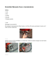
Manuale di Uso e Manutenzione
Owner’s Manual
Italiano
English
www.frmbike.com
Manufactured and distributed by:
FRM Bike Technology
Via Mattei 18/a 48025 Riolo Terme (Ra) ITALY
Phone +39 0546 70310 fax 74623
e-mail [email protected]
ITALIANO
Congratulazioni
Congratulazioni per aver scelto la FRM ANAKIN FULL.. E’ una MTB estremamente sofisticata che richiede cura ed attenzione. E’
assolutamente necessario leggere questo manuale prima di montare o usare la bici.
Il telaio è utilizzabile esclusivamente per il Cross Country.
Qualsiasi altro uso improprio limita la responsabilità del costruttore.
Per ottenere le migliori
migliori prestazioni, il telaio deve essere ass
assemblato con componenti idonei. Si raccomanda di seguire le seguenti istruzioni.
FORCELLA:
Il tubo di sterzo accetta cannotti conici 1,5” - 1 1/8”. La corsa consigliata è di 100mm. Non montare forcelle a doppia piastra.
MOVIMENTO CENTRALE:
La scatola movimento è di tipo Press-Fit Shimano. Diametro interno 41mm. Larghezza 89,5mm, simmetrica.
CORONE GUARNITURA:
Disegnata per guarniture singole o doppie. Controllare che la linea catena sia quella specificata dal produttore della guarnitura
DERAGLIATORE:
Se necessario, utilizzare deragliatori di tipo Direct-Mount S3 per corone 36 denti, con tiro dal basso
GUAINE COMANDI :
I comandi del cambio e dell’eventuale deragliatore sono interni. Le loro guaine partono dai relativi comandi, si interrompono agli stop guaina a lato del tubo
obliquo. I cavi escono dalla asola presente nella nicchia sottoscatola. Il tubo del freno idraulico entra nel foro sul lato del tubo obliquo ed esce dalla stessa asola
nella nicchia sottoscatola. Cavi comando e tubo freno idraulico passano attraverso un apposito stop triplo in plastica, dal quale partono poi i tratti di guaina per il
cambio posteriore e per l’eventuale deragliatore
FRENI :
Il supporto per il freno a disco è di tipo Post-Mount per dischi da 160mm, posizionato all’interno dei foderi orizzontali e verticali
REGGISELLA :
Il diametro del reggisella è di 31,6 mm. Scegliere il reggisella in modo che almeno 80mm ne rimangano all’interno del telaio.
MANUTENZIONE
Non lavare mai la bici con prodotti o solventi derivati dal petrolio (benzina, petrolio, nafta ecc) che sciolgono il grasso dei mozzi, movimento centrale e sterzo, ma
solo con detergenti o saponi ad acqua. Dopo il lavaggio, asciugare e ungere catena, pedali, movimento e deragliatori con oli specifici.
MANUTENZIONE
Si richiede una manutenzione simile a quella riservata ad altri telai da MTB.
Prima di ogni uscita
Controllare la forcella anteriore.
Controllare il serraggio dell’attacco manubrio e del manubrio.
Controllare il gioco dello sterzo.
Controllare la tensione degli sganci.
Controllare il funzionamento dei freni e l’usura dei pattini.
Controllare il funzionamento di cambio e deragliatore.
Controllare la pressione delle gomme.
Controllare che le ruote siano centrate
Ogni 33-6 mesi
Sostituire l’olio della forcella.
Smontare, pulire e ingrassare lo sterzo ed il movimento centrale.
Smontare, pulire ed ingrassare i mozzi.
Sostituire guaine e cavi del cambio, deragliatore e freni.
Smontare, pulire ed ingrassare gli snodi della sospensione.
SMONTARE LA SOSPENSIONE
ATTREZZI NECESSARI:
NECESSARI:
chiave a brugola da 3mm
due chiavi a brugola da 6mm
1 Sfilare i perni dell’occhio superiore ed inferiore ammortizzatore dopo aver svitato
le viti a brugola conica con chiave da 3mm.
2 Smontare l’ammortizzatore dal telaio
3 Separare il braccio superiore sospensione dalla biella svitando i due bulloni di
fissaggio con due chiavi contrapposte a brugola da 6mm. Sfilati i bulloni si
separa dalla biella un tubo distanziale di irrigidimento. Attenzione alle rondelle
distanziali ed agli O-Ring che si trovano tra la biella e le estremità della
sospensione.
4 Controllare i movimenti sia della biella che della sospensione sul telaio. Devono
essere fluidi, omogenei e senza alcun gioco.
5 Separare la sospensione dal telaio svitando i due bulloni di fissaggio con due
chiavi contrapposte a brugola da 6mm. Attenzione alle rondelle distanziali ed agli
O-Ring che si trovano tra il telaio e le estremità della sospensione.
6 Separare la biella dal telaio svitando i due bulloni di fissaggio con due chiavi
contrapposte a brugola da 6mm. Attenzione alle rondelle distanziali ed agli ORing che si trovano tra il telaio e la biella.
7 Se necessario, smontare i cuscinetti dalle loro sedi e sostituirli con nuovi di tipo
MAX a pieno riempimento di sfere (Full Complement Balls)
MONTARE LA SOSPENSIONE
ATTREZZI NECESSARI:
chiave a brugola da 3mm
due chiavi a brugola da 6mm
frenafiletti medio
grasso idrorepellente da cuscinetti
1 Ingrassare i sei cuscinetti su ambedue le loro facce.
2 Bagnare con un paio di gocce di frenafiletti medio il filetto dei sei bulloni di
alluminio e delle due viti in acciaio a testa conica
3 Posizionare la parte bassa della sospensione in corrispondenza del perno
filettato del telaio, interponendo tra cuscinetti e telaio una rondella + O-Ring per
lato. Infilare due bulloni (corti) con il loro O-Ring ed avvitarli con due chiavi a
brugola da 6mm contrapposte. Serrare a 10Nm
4 Verificare che il movimento braccio della sospensione sia fluido, omogeneo e
senza giochi
5 Posizionare i fori alti della biella in corrispondenza del perno filettato del telaio,
interponendo tra cuscinetti e telaio una rondella + O-Ring per lato. Infilare due
bulloni (corti) con il loro O-Ring ed avvitarli con due chiavi a brugola da 6mm
contrapposte. Serrare a 10Nm
6 Verificare che il movimento della biella sia fluido, omogeneo e senza giochi
7 Posizionare la parte alta della sospensione in corrispondenza dei fori bassi della
biella, interponendo tra cuscinetti e biella una rondella + O-Ring per lato. Inserire
all’interno della biella il tubo distanziale in alluminio filettato. Infilare due bulloni
(lunghi) con il loro O-Ring ed avvitarli al tubo distanziale con due chiavi a brugola
da 6mm contrapposte. Serrare a 10Nm
8 Verificare che il movimento della sospensione sia fluido, omogeneo e senza
giochi
9 Inserire l’ammortizzatore infilando i relativi perni di fissaggio: quello lungo
nell’occhio superiore e quello corto nell’occhio inferiore tra ammortizzatore e
biella
10 Infilare le viti a testa svasata M5x10 nelle relative rondelle coniche ed avvitarle nei
perni di fissaggio con chiave a brugola da 3mm. Serrate a 5Nm
TARARE L’AMMORTIZZATORE
Interasse ammortizzatore 165mm
SAG
La pressione dell’aria, immessa con una pompa dotata di valvola Shraeder,
determina il sag (affondamento) che si determina con il ciclista, in ordine di marcia,
seduto in sella . Si consiglia un sag di 88-9 mm.
mm. Un O-Ring filato sullo stelo
dell’ammortizzatore aiuta a calcolare questa distanza
Attenzione
Attenzione: l’ammortizzatore non deve comprimersi per più di 12mm
12mm con il peso
del ciclista in sella. Oltre questo limite è molto facile raggiungere il fondocorsa con
conseguenti problemi strutturali dell’ammortizzatore e/o del telaio. La corsa totale
dell’ammortizzatore è di 37mm, per una corsa alla ruota di 100mm
PROCEDURA PER CALIBRARE LA PRESSIONE DELL’ARIA
Immettere aria nella valvola con una pompa ad alta pressione dotata di valvola
Shraeder. Far scivolare l’O-Ring sullo stelo dell’ammortizzatore completamente
verso l’alto. Salire in sella appoggiando le mani sul manubrio, nella posizione della
pedalata.. Scendere lentamente dalla bici e misurare lo spostamento dell’O-Ring
sullo stelo, ovvero la distanza tra l’O-Ring e il paraolio. Se l’ammortizzatore affonda
troppo occorre ripetere l’operazione dopo aver aumentato leggermente la
pressione. Se, al contrario, l’ammortizzatore non affonda a sufficienza, occorre
sgonfiarlo leggermente. Dopo un certo numero di prove sarà evidente a quale
pressione si deve gonfiare l’ammortizzatore perché il sag sia quello giusto. E’
evidente che chi utilizza la bici per puro escursionismo cercherà il massimo del
confort e probabilmente utilizzerà una pressione inferiore a quella in tabella, che
permetta di raggiungere un sag di 8 - 9 mm, mentre gli agonisti, che prediligono la
prestazione, possono aumentare la pressione in modo da ottenere un sag inferiore.
La possibilità di bloccare l’ammortizzatore nei momenti di rilancio della velocità offre
comunque la possibilità di mantenere la pressione a livelli normali. L’O-Ring infilato
sullo stelo dell’ammortizzatore permette anche di controllare la corsa massima
raggiunta dopo una discesa. Nel caso in cui, per particolari stili di guida, non si
riesca mai a sfruttare tutta al corsa dell’ammortizzatore sarà bene diminuire la
pressione. Il contrario ovviamente se, per una guida particolarmente aggressiva si
raggiunge troppo frequentemente il fondocorsa.
PROCEDURA PER CALIBRARE LA VELOCITA’ DI RITORNO
Vedi istruzioni dello specifico ammortizzatore montato sul telaio
BLOCCO DELLA SOSPENSIONE
Vedi istruzioni dello specifico ammortizzatore montato sul telaio
MANUTENZIONE
L’ammortizzatore va lavato e pulito dopo uscite particolarmente sporche. Il fango
che si secca sullo stelo può infatti danneggiare le tenute idrauliche. Durante il
lavaggio accertarsi che il tappo di protezione della valvola dell’aria sia avvitato. Non
è prevista la sostituzione dell’olio all’interno dell’ammortizzatore se non nel caso in
cui questo presenti dei problemi di funzionamento. Lo smontaggio
dell’ammortizzatore va eseguito solo da centri specializzati col permesso del
produttore.
La garanzia decade automaticamente nel caso in cui si smonti l’ammortizzatore
senza autorizzazione.
GARANZIA
I prodotti FRM sono garantiti contro difetti di materiale e costruzione per un periodo di 2 anni dalla data di acquisto del primo utilizzatore, certificata dallo scontrino fiscale del negozio.
La garanzia decade nel caso in cui la manutenzione ordinaria o straordinaria consigliata in questo manuale non sia stata eseguita OBBLIGHI: in caso di vizio, FRM si impegna ad effettuare la
sostituzione o la riparazione, a sua discrezione dell’elemento riconosciuto difettoso. Per essere accettato, il difetto deve essere comunicato dal legittimo proprietario al negoziante dove il prodotto è
stato acquistato e da quest’ultimo, dopo averlo verificato, alla FRM Nel caso in cui la FRM non riconosca l’esistenza del difetto o stabilisca che questo è dovuto ad una delle cause riportate nel
seguente paragrafo, la sostituzione non è dovuta ed il componente viene restituito a spese del destinatario LIMITI: la garanzia non copre i danni risultanti da trasporto, giacenza, incidenti, negligenze,
colpi o cadute, mancato rispetto delle informazioni del libretto istruzioni, montaggio errato o con prodotti non compatibili, cattiva manutenzione, usura normale, modifiche o alterazioni del prodotto.
La Garanzia non copre le parti soggette a normale usura (cuscinetti, paraolio ecc.)
------------------------------------------------------------------------------------------------------------------------------------------ENGLISH
Thank you for making the Anakin Full frame your choice in full suspension.
It is mandatory to read this manual entirely prior to working on your bike.
This frame has been designed exclusively for Cross Country riding
Any other improper use will void your warranty
The use of double-triple crown front forks will void your warranty
To obtain the best performance results, this frame must be assembled with the correct
correct components.
components. Please follow these instructions.
FRONT
FRONT FORK:
FORK
Head tube is for tapered 1,5” - 1 1/8” fork steerers. Suggested wheel travel is 100mm. Never install double-triple crown forks.
BOTTOM BRACKET:
BRACKET
Shimano Press-Fit standard. Inner bore 41mm Length 89,5mm symmetric
CHAINRINGS:
Designed for single or double cranksets. The chainline is specified by the crankset manufacturer
FRONT DERAILLEUR:
DERAILLEUR:
If necessary install bottom-pull Direct-Mount S3 type front derailleurs for 36t chainrings
CABLES :
The rear and front derailleur cable guides are internals. Their housings start from shifters to the stops on the down-tube sides. Steel wires exits from the down-tube
from a oval window located in front of the bb shell. The rear brake housing is internal as well. As a single continuous unit inside the down-tube, it exits form the
same window under the frame. Derailleur wires and hydraulic housing run through a plastic triple plug to their final destinations
BRAKES :
Post-Mount disc support for 160mm disc rotors
SEATPOST :
Seat-post diameter is 31,6 mm. Make sure that there is at least 80 mm of seat-post tube inside the frame
MAINTENANCE
Never clean the bike with petroleum-based products or solvents (petrol, gasoline, diesel, etc.) as they will dissolve the grease in the bearings.
After washing, wait until the bike is dry, then lubricate the chain, pedals, bottom bracket, hubs and derailleurs.
MAINTENANCE
This frame requires a maintenance regime similar to that of any type of MTB.
Before every ride
Check the front fork.
Check bolt tension of the stem.
Check headset play.
Check tension of quick releases.
Check brake efficiency.
Check front and rear derailleur efficiency.
Check tire pressure.
Check wheel trueness
Every 33-6 months
Replace fork oil
Disassemble, clean and grease the headset, and bottom bracket
Disassemble, clean and grease the front and rear hubs.
Replace derailleur and brake cable guides.
Disassemble, clean and grease all suspension pivot points.
Allen keys. Tighten at 10Nm
4 Check that the suspension strut turns freely and smoothly without play.
5 Align the upper ends of the rocker-arm with the threaded frame stud located in
the top tube. Insert two aluminium washers + O-Rings between the frame stud
and both ends of the rocker-arm. Slide two short bolts with their O-Rings into the
bearing bores and screw them with two opposed 6mm Allen keys. Tighten at
10Nm
6 Check that the rocker-arm turns freely and smoothly without play.
7 Align the upper ends of the suspension strut with the rocker-arm lower ends.
Insert two aluminium washers and O-Rings between the rocker-arm and both
ends of the suspension strut. Position the stiffening threaded tube inside the
wings of the rocker-arm. Slide two bolts (long) with their O-Rings into the bearing
bores and screw them with two opposed 6mm Allen keys. Tighten at 10Nm
8 Check that the suspension and rocker-arm turn freely and smoothly without play.
9 Position the shock into its seats and slide the long axle into the upper eye and
the short axle into the lower eye
10 Slide the M5 cone-headed bolts into their conical washers and screw them into
the shock axles with a 3mm Allen key. Tighten at 5Nm
SUSPENSION DISASSEMBLY
REAR SHOCK TUNING
TOOLS:
Required rear shock length: 165mm
SAG
One 3mm Allen key
Two 6mm Allen keys
1 With the 3mm Allen key unscrew the cone-headed bolts at the upper and lower
ends of the shock and slide both axles out of the shock eyes
2 Disassemble the shock from the frame.
3 With two 6mm Allen keys unscrew the bolts at the upper ends of the suspension
strut. Pay attention to the washers and O-Rings which are seated between the
rocker-arm and the upper ends of the suspension strut. Rocker-arm and
suspension are now separated
4 Check any eventual play of both the rocker-arm and the suspension strut. It
should turn freely and smoothly without play.
5 With two 6mm Allen keys unscrew the bolts at the lower ends of the suspension
strut. Pay attention to the washers and O-Rings which are seated between the
rocker-arm and the upper ends of the suspension strut. Frame and suspension
are now separated
6 With two 6mm Allen keys unscrew the bolts at the upper ends of the rocker-arm.
Pay attention to the washers and O-Rings which are seated between the rockerarm and the upper ends of the suspension strut. Frame and rocker-arm are now
separated
7 If necessary, bearings can be disassembled by tapping them out of their seats
with a plastic rod and mallet. Replace exclusively with MAX type bearings (Full
Complement Balls)
SUSPENSION ASSEMBLY
TOOLS:
One 3mm Allen key
Two 6mm Allen keys
Medium Thread Compound
Water-proof bearing grease
1 Grease all bearings on both faces
2 Put a few drops of Loctite Medium compound on the thread of all bolts
3 Align the lower ends of the suspension strut with the threaded frame stud located
just over the bb shell. Insert two aluminium washers and O-Rings between the
frame stud and both ends of the suspension strut. Slide two bolts (short) with
their O-Rings into the bearing bores and screw them with two opposed 6mm
The suggested
suggested sag has
has been determined as 8mm.
8mm. This sag level is about 1/4 of the
total shock travel. It means that the rear shock should shorten by 8mm with the
cyclist sitting on the saddle.
Warning
Warning:
rning: a sag higher than 1111-12mm
12mm is detrimental to the shock functional
capacity. Beyond this limit it is very easy to bottom out, with negative consequences
on the shock and/or frame structure. The total travel of the shock is 37mm, which
translates into 100mm of wheel travel.
AIR PRESSURE CALBRATION PROCEDURE
Unscrew the cap of the valve (positive chamber) and inflate with a fork pump fitted
with Shraeder adaptor.
NOTE:
NOTE if you re-attach the pump, the hose will re-fill with air. This will result in a
lower PSI registering of approximately 15 to 20 PSI on the gauge. Sit on the saddle
and measure the shock sag. If the shock over-sags de-pressurize the chamber and
repeat the procedure to a slightly lower pressure. If the shock under-sags increase
the pressure. After a few tests the correct pressure for optimum sag will become
evident. It is clear that if the bike is used simply for sport, the rider should tune the
suspension as confortably as possible (9-10 mm of sag) and will probably obtain
the best results at pressures which are slightly lower than those of the table. The
pro-racers however may prefer to sacrifice comfort for a stiffer suspension. In this
case we suggest increasing the pressure until the bobbing is minimal. The low
progression of the spring rate, achieved with variable volumes of the air-chamber
allows up to 10% more travel available at the some pressure of a shock with
constant air chamber volume. This means that you can use an higher pressure in
order to avoid bobbing and nevertheless use the whole travel of the shock if
needed.
REBOUND DAMPING CALIBRATION PROCEDURE
Read the manual of the shock which has been installed on the frame
LOCKLOCK-OUT
Read the manual of the shock which has been installed on the frame
MAINTENANCE
The shock should be washed and cleaned after wet and muddy rides. Mud drying
on the stanchions can in fact damage the seals. During washing make sure that the
air-valve cap is securely in place. The oil inside the shock need not be replaced
unless there are functional difficulties. The shock-unit should only be disassembled
by specialists authorized by the manufacturer. The guarantee will be void if the
shock-unit is disassembled without prior authorisation
WARRANTY
FRM products are guaranteed against any defects for a period of 2 years from the date of purchase by the first owner, registered in a dealer shop.
OBLIGATIONS: In case of defects, FRM pledge to replace or repair, at their discretion, the part recognised as defective. To be accepted, the rider compliant must be
communicated to FRM through the dealer/importer after his own control. If FRM after sales checking reveals that the damage is due to one of the reasons mentioned in the
following paragraph, the replacement is no longer accepted and the defective item is sent back to the plaintiff who supports the shipping fees. LIMITATIONS: The guarantee
does not cover damage resulting from transportation, warehousing, accidents, negligence, impact or falls, non-compliance with the information in the instruction manuals,
assembly errors, assembly using non-compatible products, bad maintenance, modifications or alterations to the product. The guarantee does not cover parts and components
subject to normal wear and tear such as ball-bearings, bushings, seals, etc.