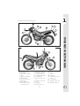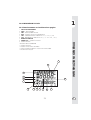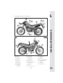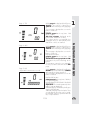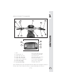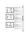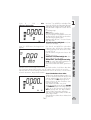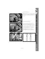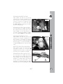
1
ALP4T 125/200cc
Grazie per la fiducia accordata e buon divertimento. Con questo libretto abbiamo voluto darLe le informazioni necessarie per
un corretto uso e una buona manutenzione della Sua moto.
I dati e le caratteristiche indicate sul presente manuale non impegnano la
BETAMOTOR S.p.A che si riserva il diritto di apportare modifiche e miglioramenti ai propri modelli in qualsiasi momento e senza preavviso.
1
I
AVVERTENZA
Si raccomanda, dopo la prima o seconda ora di utilizzo in
fuoristrada, di controllare tutti i serraggi con particolare attenzione a:
•
•
•
•
•
•
•
•
corona
supporti pedane
pinza freno anteriore
supporto parafango
bulloneria motore
bulloneria ammortizzatore
raggi ruota
telaietto posteriore
AVVERTENZA
In caso di interventi da eseguire sulla moto rivolgersi alla catena
di assistenza autorizzata Betamotor.
I
2
CAP. 1 INFORMAZIONI GENERALI ............................................. 7
Dati identificazione veicolo ...................................................................... 8
Fornitura ............................................................................................... 8
Carico ................................................................................................. 9
Pneumatici ............................................................................................ 9
Conoscenza del veicolo ........................................................................ 11
Chiavi e serrature ................................................................................. 12
Commutatore / bloccasterzo ................................................................. 12
Serratura casco ................................................................................... 12
Cruscotto e comandi ............................................................................ 13
Istruzioni di settaggio e funzionamento contachilometri ................................ 14
Dati tecnici generici .............................................................................. 31
Dati tecnici motore ALP125 .................................................................... 33
Dati tecnici motore ALP200 .................................................................... 34
Schema elettrico ALP125 ....................................................................... 35
Schema elettrico ALP200 ....................................................................... 37
Dispositivi elettrici ................................................................................. 39
CAP. 2 UTILIZZO DEL VEICOLO ................................................ 41
Controlli e manutenzione prima e dopo l’utilizzo in fuoristrada ...................... 42
Lubrificanti e liquidi consigliati ................................................................ 43
Rodaggio ........................................................................................... 43
Avviamento del motore .......................................................................... 44
Arresto del motore ................................................................................ 45
Rifornimento carburante ......................................................................... 46
INDICE
Avvertenze sull’uso ................................................................................. 5
Guida ecologica ................................................................................... 5
Guida sicura ......................................................................................... 6
CAP. 3 CONTROLLI E MANUTENZIONE .................................... 47
Olio motore e filtro olio ALP200 ............................................................. 48
Olio motore e filtro olio ALP125 ............................................................. 50
Tubo raccolta fumi ................................................................................ 51
Olio pompa freni, spurgo freni ............................................................... 51
Olio forcelle ........................................................................................ 53
Filtro aria ............................................................................................ 54
Candela ............................................................................................. 55
Freni: anteriore, posteriore ..................................................................... 56
Batteria .............................................................................................. 57
Rimozione carrozzeria .......................................................................... 58
Note per trial ...................................................................................... 59
Pulizia del veicolo e controlli .................................................................. 61
Manutenzione programmata .................................................................. 62
Lunga inattività del veicolo ..................................................................... 63
3
I
CAP. 4 REGOLAZIONI ............................................................. 65
Regolazione freni ................................................................................. 66
Regolazione frizione ............................................................................. 66
Regolazione minimo ............................................................................. 67
Regolazione flusso benzina (solo per ALP125) ........................................... 67
Regolazione gioco gas ......................................................................... 67
Controllo e regolazione gioco sterzo ....................................................... 68
Tensionamento catena .......................................................................... 69
Fascio luminoso ................................................................................... 70
CAP. 5 SOSTITUZIONI ............................................................. 71
Sostituzione pastiglie freni ...................................................................... 72
Sostituzione lampada faro anteriore ......................................................... 74
Sostituzione lampada faro posteriore ....................................................... 74
Sostituzione lampade indicatori di direzione ............................................. 75
INDICE
CAP. 6 COSA FARE IN CASO DI EMERGENZA ........................... 77
I
INDICE ALFABETICO ............................................................................ 79
4
AVVERTENZE SULL’USO DEL VEICOLO
• Il veicolo deve essere obbligatoriamente corredato di: targa, libretto di circolazione, bollo ed assicurazione.
• È vietato il trasporto di animali e oggetti non resi solidali al veicolo, che sporgono
dall’ingombro del veicolo stesso e che superino il carico previsto dal Costruttore.
• Il casco è obbligatorio.
• Viaggiare con luci anabaglianti sempre accese.
• Modifiche al motore o altri organi che possano determinare un aumento di potenza e quindi di velocità, è punita dalla legge con severe sanzioni, tra le quali la
confisca del mezzo.
• Per salvaguardare la tua vita e quella degli altri guidare con prudenza e portare
sempre il casco di sicurezza e le luci anabaglianti sempre accese
ATTENZIONE:
Modifiche e manomissioni durante il periodo di garanzia, esimono il Costruttore
da qualsiasi responsabilità e fanno decadere la garanzia stessa.
GUIDA ECOLOGICA
• Ogni veicolo con motore a scoppio produce più o meno rumore (inquinamento
acustico) e più o meno (inquinamento atmosferico) a seconda del tipo di guida
adottato.
• L’abbattimento, per quanto più possibile, di queste condizioni è oggi un dovere
per tutti, quindi evitare partenze a tutto gas, improvvise ed inutili accelerazioni ed
improvvise ed altrettanto inutili frenate, limitando così la rumorosità, l’usura precoce dei pneumatici e delle parti meccaniche del veicolo e risparmiando notevolmente sui consumi di carburante.
5
I
GUIDA SICURA
• Rispettare il Codice Stradale
• Indossare sempre casco omologato ed allacciato
• Mantenere sempre pulita la visiera protettiva
• Indossare indumenti senza estremità penzolanti
• Non viaggiare con in tasca oggetti acuminati o fragili
• Regolare correttamente lo specchietto retrovisore
• Guidare sempre seduti e con entrambe le mani sul manubrio ed i piedi sulle pedane
• Mai distrarsi o farsi distrarre durante la guida
• Non mangiare, bere, fumare, usare il cellulare, ecc... durante la guida
• Non ascoltare musica in “cuffia” durante la guida
• Non viaggiare mai appaiato ad altri veicoli
• Non trainare o farsi trainare da altri veicoli
• Mantenere sempre le distanze di sicurezza
• Viaggiare con le luci anabbaglianti accese anche di giorno
• Non sostare seduti sul veicolo in cavalletto
• Non partire con il veicolo sul cavalletto
• Non estrarre il cavalletto con il fronte/marcia del veicolo in discesa
• Impennate, serpentine, ondeggiamenti, sono pericolosissimi per Te, per gli altri e
per il Tuo veicolo
• Su strada asciutta e senza ghiaia o sabbia, usare entrambi i freni, uno solo può
causare slittamenti pericolosi ed incontrollabili
• In caso di frenata utilizzare entrambi i freni, ottenendo così un arresto del veicolo
in spazi più brevi
• Su strada bagnata, guidare con prudenza ed a velocità moderata: usare i freni
con maggior sensibilità
• Non avviare il motore in ambienti chiusi.
I
6
1
INDICE ARGOMENTI
CAP. 1 INFORMAZIONI GENERALI
Dati identificazione veicolo
Fornitura
Carico
Pneumatici
INFORMAZIONI GENERALI
Conoscenza del veicolo
Chiavi e serrature
Commutatore / bloccasterzo
Serratura casco
Cruscotto e comandi
Indicazioni su LCD
Dati tecnici
Schema elettrico
Dispositivi elettrici
7
I
1
DATI IDENTIFICAZIONE VEICOLO
IDENTIFICAZIONE TELAIO
I dati di identificazione A sono impressi
sul canotto dello sterzo nel lato destro.
I dati di identificazione B del motore sono
impressi nella zona indicata in figura.
INFORMAZIONI GENERALI
A
ATTENZIONE:
l’alterazione dei numeri di identificazione è severamente punita ai sensi di legge.
IDENTIFICAZIONE MOTORE ALP 125
IDENTIFICAZIONE MOTORE ALP 200
B
B
FORNITURA
• Il veicolo viene fornito pronto per l’uso, tuttavia si consiglia di effettuare alcuni
semplici controlli prima di utilizzarlo su strada:
- verificare la corretta pressione dei
pneumatici (in occasione del primo rifornimento di carburante);
- controllare il livello dell’olio del motore.
• Il corredo di serie comprende: il manuale d’uso e manutenzione, il set di
attrezzi (chiave candela, cacciavite
doppio uso), inseriti in una busta di plastica nel vano apposito posto sotto la
sella.
I
8
1
CARICO
PNEUMATICI
ATTENZIONE:
Per una guida sicura controllare frequentemente i pneumatici.
• Mantenere la pressione dei pneumatici
entro i limiti indicati.
• Effettuare il controllo della pressione ogni
15 giorni.
• Verificare la pressione solamente a pneumatici freddi.
pressione giusta
PNEUMATICI
Marca: MICHELIN
Tipo: Trial competition TT
PNEUMATICO
Dimensioni
Pressione bar
Pressione a pieno
carico bar
pressione troppo bassa
ANT.
2,75 - 21”
0,8
POST.
4,00 - 18”
0,6
1,3
1,3
pressione troppo alta
INFORMAZIONI GENERALI
• Carico massimo (conducente + passeggero): 280 Kg.
• Non trasportare assolutamente oggetti voluminosi o troppo pesanti, che potrebbero pregiudicare la stabilità del veicolo.
• Non trasportare oggetti che sporgano dal veicolo o che coprano i dispositivi
d’illuminazione e di segnalazione.
Il veicolo è omologato anche con pneumatici tutto terreno:
Marca: PIRELLI
Tipo: Scorpion
PNEUMATICO
Dimensioni
Pressione bar
ANT.
POST.
90/90 - 21” 120/80 - 18”
1,6
1,8
9
I
INFORMAZIONI GENERALI
1
I
Nota:
Lo spessore minimo del battistrada dei pneumatici (TUBE TYPE) non deve mai essere
inferiore ai 2 mm.
La mancata adempienza a questa norma è punita ai sensi di legge.
• Controllare prima di ogni viaggio che i pneumatici non presentino tagli, screpolature, abrasioni, rigonfiamenti, ecc... In questi casi far esaminare il pneumatico da
un esperto in quanto potrebbero verificarsi condizioni estremamente pericolose.
• In caso di foratura arrestare subito il veicolo; proseguire la marcia, oltre ad essere
rischioso, può provocare irrimediabili danni al pneumatico ed al cerchio ruota.
• In condizioni di max. carico sono consigliate pressioni maggiori (vedi tabella a
pag. 9).
10
1
CONOSCENZA DEL VEICOLO
4
3
2
11
22
6
8
7
1
5
10
12
17
14
20
19
18
21
13
Elementi principali:
1- Filtro aria
2- Serbatoio carburante
3- Tappo carburante
4- Silenziatore
5- Ammortizzatore
posteriore
6- Faro anteriore
7- Indicatori di direzione anteriori
16
15
8- Fanale posteriore
9- Indicatori di direzione posteriori
10 - Cavalletto laterale
11 - Portapacchi
12 - Specchi retrovisori
13 - Pedane passeggero
14 - Forcella
15 - Pedane pilota
11
INFORMAZIONI GENERALI
9
16 - Carter sotto motore
17 - Sella
18 - Motore
19 - Parafango anteriore
20 - Portatarga
21 - Leva messa in moto
22 - Serratura casco
I
1
CHIAVI E SERRATURE
Il veicolo viene fornito con due chiavi e le relative scorte da utilizzarsi per il commutatore/bloccasterzo e per la serratura casco.
INFORMAZIONI GENERALI
ATTENZIONE:
Non conservare la chiave di scorta all’interno del veicolo, ma in luogo sicuro ed a
portata di mano. Consigliamo di registrare sul presente manuale (o altrove) il numero di codice impresso sulle chiavi. In caso di smarrimento di entrambe si potranno
richiedere dei duplicati.
I
COMMUTATORE/BLOCCASTERZO
Controlla il circuito di accensione, l’inserimento del bloccasterzo e l’apertura sella.
OFF: Sistema elettrico disattivato.
ON: Si può effettuare l’accensione del
veicolo.
LOCK: Inserimento del bloccasterzo.
Per questa operazione occorre
sterzare il manubrio a sinistra,
premere sulla chiave, ruotarla
completamente in senso antiorario e dopo rilasciarla.
OFF
ON
LOCK
SERRATURA CASCO
Inserire la chiave più piccola nella serratura posta sul lato sinistro sotto la sella, e
ruotarla in senso antiorario per aprire il gancio portacasco.
12
1
CRUSCOTTO E COMANDI
11
1
19
17
18
13
12
16
4
15
14
8
9
7
5
6
1- LCD
4- Commutatore a chiave
5- Spia punto neutro
6- Spia indicatori di direzione
7- Spia abbaglianti
8- Spia riserva carburante
9- Spia cavalletto
10 - Leva frizione
11 - Leva freno anteriore
12 - Manopola acceleratore
13 - Pulsante accensione
14 - Pulsante stop motore
15 - Pulsante indicatori di direzione
16 - Pulsante clacson
17 - Interruttore luci
18 - Deviatore luci
19 - Passing
INFORMAZIONI GENERALI
10
Nota: l’accensione della spia cavalletto indica la posizione abbassata del cavalletto stesso. Per ragioni di sicurezza la moto si spegne all’inserimento della marcia.
13
I
1
ISTRUZIONI DI SETTAGGIO E FUNZIONAMENTO CONTACHILOMETRI
(per costruttore e concessionario)
La descrizione relativa al setup di base dello strumento digitale riveste un carattere
puramente informativo; è consigliabile rivolgersi ad un Officina autorizzata Betamotor
per effettuare questa operazione.
Serie ALP 125 - ALP 200
INFORMAZIONI GENERALI
INDICE DEGLI ARGOMENTI
I
PARAGRAFO
CONTENUTO
10.1
10.2
10.3
10.4
Caratteristiche ruota
Caratteristiche motore
Precaricamento codici
Codici caricati
20.0
20.1
20.2
20.3
20.4
20.4.1
20.4.2
20.4.3
20.4.3.1
20.4.4
20.4.5
20.4.6
20.5
SETUP LIVELLO 1 (per costruttore moto e concessionario)
Esecuzione setuo livello 1
Selezione codici
Verifica contenuto codici
Inserimento valori non codificati
Inserimento Ln (sviluppo ruota) o di (diametro ruota)
Inserimento numero impulsi giro ruota
Inserimento numero impulsi giro motore
Inserimento numero giri massimi motore
Selezione Km/h o Mph
Inserimento ore per cambio olio
Inserimento ore o Km per tagliando
Uscita da setup
40.0
40.1
40.2
40.3
LCD DISPLAY
Funzionamento e visualizzazione pagine
Oscuramento delle pagine
Cancellazione parametri TRP, SPEED max, LAP
50.0
50.1
IIntervento delle icone di sorveglianza (olio motore e tagliando)
Verifica del contenuto attivo delle icone di sorveglianza
14
NB: le azioni sul pulsante SCROLL sono di due tipi:
Azionamento breve ≤ 1” il programma passa alla pagina successiva.
Azionamento lungo ≥ 5” il programma permette di entrare nella funzione
visualizzata per verificare il contenuto o per inserire/modificare i valori contenuti e
in alcuni casi esegue la memorizzazione.
Nella presente documentazione, per comodità di esposizione si usa indicare solo il
tasto SCROLL su manubrio, ma si ottengono i medesimi risultati anche usando tasto
MODE sul contachilometri (il pulsante MODE azionabile solo a moto ferma).
10.2 Caratteristiche motore (solo se è attivo il contagiri)
Numero impulsi al giro e giri nominali massimi necessari per calibrare la barra.
L’eventuale inserimento dei parametri, con sensore assente, non modifica il funzionamento, ma aprirà ugualmente la pagina su LCD con parametri e barra a zero.
L’entrata del sensore è su pin 12 del connettore. Il numero d’impulsi giro rispetta le
medesime regole del numero impulsi giri ruota, mentre il numero di giri motore
richiede solo le migliaia e le centinaia. Esempio: per inserire 15000 giri dovrà
essere inserito 150 sulle cifre grandi, per inserire 8500 giri dovrà essere inserito
085 sulle cifre grandi.
10.3 Precaricamento codici (già impostati sul veicolo)
Sono già inseriti dal costruttore quattro codici predefiniti che contengono sempre i
parametri ruote e parametri di sorveglianza come “ore cambio olio” e “ore o km al
tagliando”. Solo i parametri di sorveglianza potranno sempre essere modificati.
L’identificazione avverrà evidenziando su LCD un numero in codice ed il primo
codice inserito sarà 0001.
I codici sono già inseriti e non saranno più modificabili se non dal costruttore. Va
evidenziato che eseguendo una riprogrammazione i km totali percorsi verranno
azzerati.
15
1
INFORMAZIONI GENERALI
10.1 Caratteristiche ruota (già impostate sul veicolo)
Dimensioni della ruota sulla quale è montato il sensore giri. Dovrà essere indicato il
diametro o lo sviluppo in mm (valori massimi 9999. Esempio: per diametro ruota di
695mm ad inserimento completato si dovrà leggere 0695) e il numero di impulsi
per ogni giro, valore massimo 99. Ad inserimento completato se il numero di impulsi minore di 10, esempio 1, si dovrà leggere 01.
I
INFORMAZIONI GENERALI
1
10.4 Codici caricati
Su ogni disegno d'assieme dei contachilometri, è riportata la tabella con i codici e
relative descrizioni.
E possibile, in qualsiasi momento, verificare il contenuto di ogni codice.
20.0 SETUP LIVELLO 1
Permette di operare scelte e inserimenti su tutti i campi e cioè:
• Selezione codice
o in alternativa:
• inserimento di
• sviluppo o diametro ruota,
• numero impulsi giro ruota,
• numero impulsi giri motore,
• numero giri massimo.
• carico o modifica dei valori di
• ore al cambio olio,
• km o ore al tagliando,
• unità di misura Km/h o Mph, l'unità di misura impostata di default
per la velocità è km/h.
20.1 Esecuzione setup livello 1
• Con strumento spento premere SCROLL e mantenerlo premuto.
• Avviare il veicolo con batteria allacciata.
• Dopo circa 7” compare WS nell'angolo in basso a destra come da figura 1
• Mantenendo SCROLL premuto, agire su abbagliante accendendolo e
spegnendolo 5 volte.
• Rilasciando SCROLL si presenta la scritta cu in figura 2 se lo strumento non ha mai
subito un’azione di setup e in alternativa la figura 3 se è già settato indicando il
codice adottato.
Figura 1
I
16
Figura 2
20.2 Selezione codici
•Premendo SCROLL brevemente si
evidenziano, in successione gli altri codici con presentazione della figura 2
alla fine.
1
Tabella codici
Alp 200 cc Motard M4
0002
0003
2115
1830
Figura 3
Figura 4
•Identificato il codice prescelto premere SCROLL mantenendolo premuto
fino alla comparsa di WS nell'angolo in basso a destra figura 4; al rilascio il codice viene attivato e si presenta figura 5.
•Se la configurazione è da ritenersi completa si presentano due possibilità:
- uscita da setup e attivazione test come
da paragrafo 40.0 spegnendo e
riaccendendo il contachilometri.
- verificare contenuto codice secondo
paragrafo 20.3.
•Se nessun codice è idoneo ripetere la
procedura fino alla comparsa della figura 2, raggiungibile premendo
SCROLL brevemente dalla figura 3,
quindi premere SCROLL fino a WS,
al rilascio si attiva la procedura del paragrafo 20.4.
17
INFORMAZIONI GENERALI
Veicolo
Alp 4.0
Codice
0001
Sviluppo 2105
ruota
I
INFORMAZIONI GENERALI
1
I
20.3 Verifica contenuto codici
É sempre possibile verificare il contenuto dei codici. Rieseguire le procedure di
setup ripetendo le operazioni dal paragrafo 20.1. A codice selezionato e memorizzato all'uscita si presenta la figura 5.
Premere SCROLL fino alla comparsa delle barre orizzontali, figura 7, al rilascio si
presenta lo sviluppo ruota abbinato al codice selezionato (non modificabile) .
Premendo brevemente SCROLL si presenta la figura 6.
Premere SCROLL fino alla comparsa delle barre orizzontali, figura 7, al rilascio si
presenta il diametro ruota abbinato al codice selezionato (non modificabile).
Premendo SCROLL brevemente si presenta la figura 8.
Premere SCROLL fino alla comparsa delle barre orizzontali al rilascio compare il
numero di impulsi per giro abbinato al codice (non modificabile).
Premendo SCROLL brevemente si presenta la figura 9.
Premere SCROLL fino alla comparsa delle barre orizzontali al rilascio compare il
numero di impulsi per giro motore abbinato al codice (non modificabile).
Premendo SCROLL brevemente si presenta la figura 10.
Premere SCROLL fino alla comparsa delle barre orizzontali al rilascio compare il
numero di giri motore abbinato al codice (non modificabile).
Proseguendo si presentano le figure successive 11,12 e 13 che, anche se abbinate
ai codici, sono sempre modificabili come da paragrafo 20.4.
Ad operazione conclusa compare la scritta End.
Con End presente premendo SCROLL brevemente si ripete il menù ritornando alla
figura 5.
Premendo SCROLL fino alla comparsa delle barre - - - - al rilascio lo strumento va
in test come da paragrafo 40.0. Il medesimo risultato si ottiene spegnendo e
riaccendendo lo strumento.
20.4 Inserimento valori non codificati
20.4.1 Inserimento Ln (sviluppo ruota)
o di (diametro ruota)
Ln (lunghezza ruota in mm): premendo
brevemente SCROLL si passa a di (diametro ruota in mm), ripremendo SCROLL
si ritorna a Ln e così via. Per procedere
oltre è necessario che almeno una delle
due grandezze sia diversa da 0.
Figura 5
18
Figura 7
Figura 8
Con figura 5 o 6 presente, ottenute eseguendo la procedura dal paragrafo 20.1
e 20.2, premere SCROLL mantenendolo premuto fino alla comparsa della figura 7.
Rilasciando SCROLL al posto delle barre si presenteranno o 0000 o il valore
precedentemente inserito con il primo numero di sinistra lampeggiante. Premendo brevemente SCROLL il numero avanza di uno. Lasciando SCROLL inattivo
per 2 secondi oscillerà il secondo numero da sinistra. Si opera come per il primo e per tutti i rimanenti.
Inserita la Ln attendere 2" fino alla scomparsa del numero.
Ripetendo l'operazione si può modificare il numero inserito.
Premendo brevemente SCROLL si presenta la figura 6. Avendo inserito la Ln,
il contenuto della pagina sarà il diametro corrispondente, calcolato automaticamente dallo strumento. Se si vuole modificare operare come per figura 7, diversamente attendere la scomparsa del numero e premendo brevemente SCROLL
si presenterà la figura 8.
20.4.2 Inserimento numero impulsi giro ruota
HALL Speed (numero impulsi al giro
ruota).
Da figura 8 premere SCROLL e mantenerlo premuto fino alla comparsa delle
barre - - - - . Al rilascio si presenta o 00
o il valore precedentemente caricato.
L’aggiornamento e il salvataggio del valore avviene con la stessa procedura di
figura 7.
Premendo SCROLL brevemente si prosegue e si presenta la figura 9.
19
1
INFORMAZIONI GENERALI
Figura 6
I
INFORMAZIONI GENERALI
1
I
20.4.3 Inserimento numero impulsi giro motore (solo se è stato
richiesto)
È possibile utilizzarlo se si dispone di un
traduttore connesso al pin 12 del
connettore inserendo i parametri manualmente. Se non è presente contagiri, mettere il valore 00 alla pagina 9 o alla
pagina 10. Questa operazione nasconde la pagina contagiri su LCD.
HALL rpm (numero impulsi giri motore).
Premere SCROLL e mantenerlo premuto
fino alla comparsa delle barre - - - -.
Al rilascio si presenta o 00 o il valore
precedentemente caricato. L’aggiornamento e il salvataggio del numero avviene con la stessa procedura di figura 7.
Premendo SCROLL brevemente si prosegue e si presenta la figura 10.
20.4.3.1 Inserimento numero
impulsi giri massimi motore
Il contagiri offre ad indicare il numero di giri
su 5 digit piccoli, utilizza anche la barra.
Per definire il fondo scala occorre inserire il
numero di giri massimo al mezzo.
Figura 9
Figura 10
Figura 11
max (numero impulsi giri motore).
Premere SCROLL e mantenerlo premuto
fino alla comparsa delle barre - - - -.
Al rilascio compariranno 000 su digit
grandi e 00 su digit piccoli. L’aggiornamento e il salvataggio del numero avviene con la stessa procedura di figura 7
tenendo presente che 100 significa
10.000 giri. A memorizzazione avvenuta ricompare la figura 10.
Premendo SCROLL brevemente si prosegue e si presenta la figura 11.
20
20.4.4 Selezione Km/h o Mph
Premere SCROLL e mantenerlo premuto
fino alla comparsa delle barre - - - -.
Al rilascio comparirà una sola unità di
misura lampeggiante e sarà quella attiva in quel momento: esempio Mph.
Premendo SCROLL brevemente verrà sostituita da Km/h.
Per confermare la selezione, con presente l’unità di misura prescelta premere
SCROLL e mantenerlo premuto fino alla
comparsa di WS nell‘angolo in basso a
destra; rilasciandolo ricompare la figura
11.
Premendo SCROLL brevemente si prosegue e si presenta la figura 12.
20.4.5 Inserimento ore per cambio olio
Premere SCROLL e mantenerlo premuto
fino alla comparsa delle barre - - - -.
L’aggiornamento e il salvataggio del valore avviene con la stessa procedura di
figura 7. Premendo SCROLL brevemente si prosegue e si presenta la figura 13.
21
1
INFORMAZIONI GENERALI
Figura 12
I
INFORMAZIONI GENERALI
1
I
20.4.6 Inserimento ore o Km per
tagliando
Premere SCROLL e mantenerlo premuto
fino alla comparsa delle barre - - - -: al
rilascio si presenterà la fig. 14.
Premendo SCROLL brevemente si alterna Km/h con CLK.
Per confermare la selezione, con presente l’unità di misura prescelta premere
SCROLL e mantenerlo premuto fino a
breve comparsa di WS nell’angolo in
basso a destra. Al rilascio inserire e salvare il valore con la stessa procedura di
figura 7; al termine della operazione si
ripresenta la figura 13. Premendo
SCROLL brevemente si prosegue e si presenta la scritta End.
Figura 13
Figura 14
Figura 15 - TEST.
20.5 Uscita da setup
Con End presente premendo SCROLL
brevemente si ripete il menù ritornando
alla figura 5.
Premendo SCROLL fino alla comparsa
delle barre - - - - al rilascio si attiva il test
(figura 15).
Il medesimo risultato si ottiene spegnendo e riaccendendo lo strumento.
Il test consiste nella verifica globale di
tutti i segmenti e di tutte le icone presenti
su LCD e test sugli indicatori luminosi.
Il test dura 3 secondi.
Al termine del test si presenterà la pagina di default.
22
1
40.0 INDICAZIONI SU LCD
40.1 Funzionamento e visualizzazione pagine
VELOCITÀ ISTANTANEA
ODO – TOTALIZZATORE
TRP – TOTALIZZATORE PARZIALE
AVS – VELOCITÀ MEDIA DEL PERCORSO TRP
LAP – CRONOMETRO NEI FORMATI hh:mm:ss e mm:ss:1/10s
CLK – OROLOGIO NEI FORMATI hh:mm:ss, con 12h e 24h, e mm:ss
BARRE CONTAGIRI
SPEED max – VELOCITÀ MASSIMA
ICONA BATTERIA
ICONA ORE CAMBIO OLIO
ICONA BENZINA
ICONA CHIAVE MANUTENZIONE
BARRA LIVELLO TENSIONE IN USCITA DALL’ALTERNATORE
TEMPERATURA ACQUA
INFORMAZIONI GENERALI
1
2
3
4
5
6
7
8
9
10
11
12
13
14
1
7
8
3
4
12
5
13
11
14
2
9
10
23
6
I
1
Successione pagine su LCD
Tutte le pagine a partire dalla pagina di default sono raggiungibili solo nella loro
sequenza.
INFORMAZIONI GENERALI
Pagina 1 - TEST.
I
Girare il commutatore a chiave su ON.
Verifica globale di tutti i segmenti e di
tutte le icone presenti su LCD e test sugli
indicatori luminosi.
Il test dura 3 secondi.
Al termine del test si presenterà la pagina di default.
Pagina 2 - PAGINA DI DEFAULT
La pagina di default si attiva automaticamente dopo il TEST.
Visualizza:
Batteria - indica lo stato di carica su
barra verticale (min 10,4V, max 14,5V).
Velocità istantanea in alto (max 199
Km/h o Mph)
ODO totalizzatore dei Km o miglia
percorsi dal primo setup. Visualizzato in
basso (percorrenza massima 999.999 Km
o miglia). Parametro non azzerabile.
24
Dalla pagina 2 con MODE a mezzo
fermo o SCROLL con veicolo in movimento, premendoli brevemente, si passa alla
pagina 3.
Il passaggio avviene al rilascio del comando.
Visualizza:
Velocità istantanea in alto (max 199
Km/h o Mph)
TRP Totalizzatore parziale visualizzata in basso (max 999.9 Km o Miglia).
Azzerabile manualmente (paragrafo 40.3)
o automaticamente al raggiungimento dei
999.9 Km o miglia
Pagina 4 - AVS
Dalla pagina 3 con MODE a mezzo
fermo o SCROLL con veicolo in movimento, premendoli brevemente, si passa alla
pagina 4.
Il passaggio avviene al rilascio del comando.
Visualizza:
Velocità istantanea in alto (max 199
Km/h o Mph)
AVS Velocità media effettiva del
percorso di TRP (calcolata solo con
mezzo in movimento) in basso.
Non azzerabile manualmente. Si azzera
con l’azzeramento della pagina TRP.
Pagina 5 - LAP
- Cronometro ore:minuti:secondi
Dalla pagina 4 con MODE a mezzo
fermo o SCROLL a veicolo in movimento,
premendoli brevemente, si passa alla pagina 5.
Il passaggio avviene al rilascio del comando.
Visualizza:
Velocità istantanea in alto (max 199
Km/h o Mph). Indica
ORE:MINUTI:SECONDI 00:00:00,
visualizzati in basso.
Funzionamento: i comandi operano
solo con pagina 5 o 6 presente.
- attivazione e arresto manuale da SCROLL
con impulso breve,
- attivazione e arresto in automatico da impulso ruota. Dopo 3 secondi dall’arresto
della ruota il cronometro cesserà di misurare, correggendo il tempo di ritardo.
25
1
INFORMAZIONI GENERALI
Pagina 3 - TRP
I
1
Pagina 6 - LAP – Cronometro
minuti:secondi:decimi di secondo
Dalla pagina 5, premendo SCROLL per
un tempo di 1,5”, si presenta per la durata di 1” la figura 21 con le barre
- - : - - in alto
Mantenendo premuto SCROLL si ripresenta la pagina 5.
Rilasciando SCROLL si presenta la pagina 6.
Visualizza:
Cronometro formato
INFORMAZIONI GENERALI
MINUTI:SECONDI 00:00,
Pagina 7 - CLK - Orologio
ore:minuti:secondi
visualizzati in alto. Utilizza 2 digit piccoli
per i decimi di secondo. Opera esattamente come pagina 5 della quale è
un’estensione.
L’azzeramento di questa pagina azzera
anche la pagina 5 e viceversa.
Velocità istantanea su digit piccoli
(max 199 Km/h o Mph)
Dalla pagina 6, premere SCROLL per un
tempo di 1,5”, si presenta per la durata
di 1” la figura 21.
Mantenendo premuto SCROLL si ripresenta la pagina 6.
Rilasciando SCROLL si presenta la pagina 7.
Visualizza:
Velocità istantanea in alto (max 199
Km/h o Mph)
Orologio ORE:MINUTI:SECONDI
in basso, 00:00:00.
Regolabile tramite MODE o SCROLL a
mezzo fermo.
Se l’unità di misura è Km/h opererà
su 24 ore
23:59:59
Se l’unità di misura è Mph opererà su
12 ore
11:59:59 con l’aggiunta di
AM/PM in automatica alla selezione di Mph.
Procedura d’impostazione dell’orologio
1°- Premere MODE o SCROLL fino al lampeggio dei numeri relativi alle ore.
2°- Rilasciare e ripremere: le ore avanzano di un numero. Mantenendo premuto avanzano automaticamente. Lasciandolo inattivo si passa al punto 4°.
3°- Rilasciare pulsante a ore raggiunte.
4°- Dopo 2” lampeggiano i minuti.
5°- Operare come al punto 2°. Lasciandolo inattivo si passa al punto 8°.
6°- Rilasciare pulsante a minuti raggiunti.
7°- Dopo 2” lampeggiano i secondi.
8°- Operare come al punto 2°.
9°- Rilasciare pulsante a secondi raggiunti e dopo 2” l’orario verrà assunto.
10° - Il cambio dell’unità di misura da Km/h a Mph adegua automaticamente l’orologio da 24 a 12 ore
I
26
Pagina 8 - CLK - Orologio minuti:secondi
Da pagina 7 con MODE a mezzo fermo
o SCROLL in movimento, premendoli brevemente si passa alla pagina 8.
Il passaggio avviene al rilascio del comando.
Visualizza:
Orologio formato
1
Pagina 10 SPEED max
Da pagina 8 con MODE a mezzo fermo
o SCROLL in movimento, premendoli brevemente si passa alla pagina 9.
Il passaggio avviene al rilascio del comando.
Visualizza:
Velocità istantanea in alto (max 199
Km/h o Mph)
SPEED max Velocità massima raggiunta dall’ultimo azzeramento.
Azzerabile manualmente.
40.2 Oscuramento delle pagine
Se qualche pagina può essere ritenuta non utile la si può rendere invisibile, pur restando sempre attiva, per accelerare il raggiungimento della pagina successiva.
Tutte le pagine, sia in blocco che singolarmente, ad esclusione della pagina 2 di
default, possono essere oscurate.
Per disattivare una pagina:
premere MODE o SCROLL dalla pagina che si vuol oscurare e mantenerlo premuto fino alla comparsa di WS nell’angolo in basso a destra dell’ LCD.
Al rilascio del pulsante la pagina non è
più visibile.
Per riattivare le pagine:
premere MODE o SCROLL da pagina
di default fino alla comparsa di WS nell’angolo in basso a destra dell’ LCD e tutte
le pagine ritorneranno visibili.
Se nessuna pagina era oscurata si oscureranno tutte.
Per riattivarle ripetere l’operazione.
27
INFORMAZIONI GENERALI
MINUTI:SECONDI 00:00
in alto. Regolabile tramite pulsante MODE
o SCROLL su minuti e secondi solo a mezzo fermo.
Aggiorna anche la pagina 7 di cui è
un’estensione.
Velocità istantanea in basso (max
199 Km/h o Mph).
I
1
40.3 Cancellazione parametri TRP, SPEED max, LAP
I parametri cancellabili sono:
- Percorso indicato da TRP e conseguentemente AVS
- SPEED max velocità massima raggiunta
Tempi indicati da LAP in entrambe le configurazioni da una qualsiasi delle 2 pagine.
La cancellazione dei parametri è attuabile con MODE a mezzo fermo e con SCROLL
sempre.
INFORMAZIONI GENERALI
Cancellazione TRP e
I
SPEED max
Premere MODE o SCROLL per un tempo
≥ 5”, dopo di che al posto del numero si
presenterà 0.0
La cancellazione del TRP è fattibile solo a
moto ferma. Tale operazione azzera anche AVS.
Cancellazione LAP
L’azzeramento del tempo di LAP azzera
sia la pagina 5 che la pagina 6 che sono
rigidamente collegate.
I numeri saranno sostituiti dalle barrette
orizzontali che rimarranno visibili per 1”.
Se in presenza delle barre - - - - viene
rilasciato MODE o SCROLL il numero viene cancellato.
Se MODE o SCROLL viene mantenuto
premuto si passa alla pagina successiva
conservando i valori della pagina.
28
50.0 INTERVENTO DELLE ICONE DI SORVEGLIANZA (olio motore e tagliando)
ICONA TAGLIANDO
ICONA BATTERIA Vb MAGGIORE DI 14,5V
Quando le ore al cambio olio raggiungono il 90% del valore impostato, su tutte le
pagine compare l’icona stabile e diventa
lampeggiante al raggiungimento del valore impostato.
Rivolgersi ad un concessionario Betamotor autorizzato.
Quando le ore o i chilometri al tagliando
raggiungono il 90% del valore impostato,
su tutte le pagine si ilumina stabilmente l’icona “tagliando”. Al raggiungimento del
valore impostato essa diventa lampeggiante.
Rivolgersi ad un concessionario Betamotor autorizzato.
Per quanto riguarda la manutenzione programmata eseguita dopo i primi 1000 km.
si farà riferimento alla tab. pag 49.
Il lampeggio della barra verticale con presente la scritta max indica che la tensione della batteria è maggiore di 14,5V. Se
la segnalazione persiste occorre verificarne la causa. Rivolgersi ad un concessionario Betamotor autorizzato.
29
INFORMAZIONI GENERALI
ICONA OLIO
1
I
INFORMAZIONI GENERALI
1
ICONA BATTERIA Vb MINORE DI 10,5V
Il lampeggio sia della barra verticale che
della batteria con presente la scritta min
indica che la tensione della batteria è minore di 10,5V. Se la segnalazione persiste occorre verificarne la causa.
ATTENZIONE. Se la batteria viene scollegata o ha una tensione prossima a zero
lo strumento pere il controllo; Tale problema è segnalato da Led Frecce e/o Led
Cavalletto accese con LCD illuminato ma
senza simboli. Per rimettere in funzione corretta lo strumento occorre o staccare il connettore o staccare il positivo di batteria per almeno 5”, di conseguenza si perderà la
regolazione dell’orologio che andrà riprogrammato.
Tutti i rimanenti dati vengono conservati.
50.1 Verifica del contenuto attivo delle icone di sorveglianza
Per le icone di sorveglianza, è sempre possibile verificare quanto manca in ore o Km
alla loro presentazione con richiesta d’intervento.
Accendere lo strumento con MODE e SCROLL premuti contemporaneamente.
Mantenendoli premuti dopo circa 5 secondi si presentano alternativamente l’icona olio
con indicato quante ore mancano al cambio e l’icona chiave indicando, a seconda
dell’unità scelta, quante ore o quanti km mancano al tagliando.
Rilasciando i pulsanti inizia il test.
SELEZIONE KM/H O MPH
Premere SCROLL e mantenerlo premuto fino
alla comparsa delle barre - - - - . Al rilascio
comparirà una sola unità di misura lampeggiante e sarà quella attiva in quel
momento: esempio Mph.
Premendo SCROLL brevemente verrà sostituita da Km/h.
Per confermare la selezione, con presente
l’unità di misura prescelta premere SCROLL
e mantenerlo premuto fino alla comparsa
di WS nell’angolo in basso a destra; rilasciandolo ricompare la figura.
Premendo SCROLL brevemente si prosegue e si presenta la figura riportata accanto.
I
30
1
DATI TECNICI
CARICO MASSIMO
conducente + passeggero ............................................................. 280 (kg)
DIMENSIONI
lunghezza totale ........................................................................ 2143
larghezza totale ........................................................................... 820
altezza totale ............................................................................ 1170
interasse ................................................................................... 1372
altezza sella ................................................................................ 836
luce a terra ................................................................................. 288
mm
mm
mm
mm
mm
mm
TELAIO ........................................................ in acciaio a doppia culla chiusa
PNEUMATICI
tipo .............................................................. Michelin - Trial Competition TT
pressione bar ................................................................ ant. 0,8/post. 0,6
pressione bar a pieno carico ........................................... ant. 1,3/post. 1,3
dimensioni ................................................. ant. 2,75 - 21”/post. 4,00 - 18”
tipo .................................................................................. PIRELLI Scorpion
pressione bar ................................................................ ant. 1,6/post. 1,8
pressione bar a pieno carico ........................................... ant. 2,0/post. 2,4
dimensioni .........................................ant. 90/90 - 21”/post. 120/80 - 18”
INFORMAZIONI GENERALI
PESO VEICOLO
in ordine di marcia (a secco) ALP200 .............................................. 103 (kg)
in ordine di marcia (a secco) ALP125 .............................................. 101 (Kg)
CAPACITÀ DI RIEMPIMENTO
serbatoio carburante ...................................................................... 6,8 (litri)
di cui lt di riserva .......................................................................... 1,5 (litri)
olio motore ................................................................................. 850 (cc)
consumo medio ........................................................................ 25 Km/litri
31
I
INFORMAZIONI GENERALI
1
I
SOSPENSIONE ANTERIORE
forcella idraulica con steli di Ø 38 mm, regolazione estensione e precarico molla
Contenuto olio nei gambi:
destro .......................................................................................... 350 cc
sinistro ......................................................................................... 350 cc
Tipo olio ................................................................ Bel Ray MC 10 SAE 10
in alternativa LIQUI MOLY RECING SUSPENSION OIL SAE 10W
Livello olio ........................................... 120 mm dal bordo superiore del tubo
con forcella a fine corsa e senza molla
avancorsa .................................................................................... 77 mm
SOSPENSIONE POSTERIORE
monoammortizzatore idraulico progressivo e regolazione in estensione e precarico
molla
corsa ammortizzatore ..................................................................... 80 mm
FRENO ANTERIORE
a disco Ø 245 mm con comando idraulico
FRENO POSTERIORE
a disco Ø 220 mm con comando idraulico
32
1
MOTORE ALP125
tipo ................................. Monocilindrico, inclinato in avanti, 4 tempi, SOHC
alesaggio x corsa ..................................................................... 54x54 mm
cilindrata (cm3) ............................................................................ 124 cm3
rapporto di compressione ................................................................... 10:1
MIKUNI UCAL 5Nh Ø26-38
lubrificazione ................................................................ Forzata con pompa
alimentazione .......... a benzina (con numero di ottano minimo 95 senza piombo)
raffreddamento ............................................................ a circolazione d’aria
candela ......................................................................... NGK R CR7 HSA
frizione ................................................................ multidisco a bagno d’olio
cambio ..................................................................................... 5 velocità
Rapporto riduzione primaria ............................................................. 68/20
Rapporto riduzione secondaria finale ................................................. 60/14
Rapporto cambio 1° ....................................................................... 37/14
2° ....................................................................... 32/18
3° ....................................................................... 25/19
4° ....................................................................... 23/22
INFORMAZIONI GENERALI
carburatore ...........................................................
5° ....................................................................... 21/24
Catena di trasmissione ............................... REGINA DERVIO 1/2, 5/16 P. 138
Gioco valvole .................. aspirazione mm 0,08 - 0,12 scarico mm 0,10-0,14
Avviamento .............................................................. elettrico e/o kick-starter
Olio motore ........................................................... BARDAHL XTM15W 50
Quantità olio motore ..................................................... 1,000 ml/1,050 ml
33
I
1
MOTORE ALP200
tipo .............................................. monocilindrico a quattro tempi
SUZUKI H402
alesaggio x corsa .................................................................. 66x58,2 mm
cilindrata (cm3) ............................................................................ 199 cm3
rapporto di compressione .................................................................. 9,4:1
INFORMAZIONI GENERALI
carburatore ..................................................................... MIKUNI BST31 42AD
lubrificazione .................................................................. con olio in coppa
alimentazione .............................................. a benzina (con numero di ottano
minimo 95 senza piombo) mediante carburatore
raffreddamento ............................................................ a circolazione d’aria
candela .................................................................................. NGK DR8 EA
frizione ................................................................ multidisco a bagno d’olio
cambio ..................................................................................... 5 velocità
Rapporto riduzione primaria ................................................. 3,157 (60/19)
Rapporto riduzione finale ..................................................... 3,200 (48/15)
Rapporto cambio 1° ........................................................... 3,000 (33/11)
2° ........................................................... 1,933 (29/15)
3° ........................................................... 1,437 (23/16)
4° ........................................................... 1,095 (23/21)
5° ........................................................... 0,913 (21/23)
Catena di trasmissione .......................... REGINA DERVIO 135 EBXL - 112 MG. c/giunto
Gioco valvole ..................................... aspirazione e scarico mm 0,08 - 0,13
Avviamento .............................................................. elettrico e/o kick-starter
Olio motore .................................................................. BARDAHL XTM15W 50
Quantità olio motore .................... cambio olio 850 ml con cambio filtro 950 ml
revisione 1300 ml
I
34
1
35
Az
Ro
Ro
19
18
Vi
Bi-Ne
Bl-Ve
Vi
Bl-Ve
Ve
Bi-Ne
Ve
Rs-Gi
16
17
Rs-Gi
Bl-Ne
15
Bl
Bi-Bl
Az
14
Bi-Bl
Bl-Ne
Bl-Ne
13
Ma
Ma
Gr
Bl-Ne
Ma
Gr-Ve
Ma-Gi
Ne
Rs
Bi-Ro
Ne
6
9
7
13
14
4
5 Ma-Ne
Gr
2 1 0
Ve
Vi
11 Bl-Ne
3 Ne-Ar
1
Bl-Ve
Bl-Ve
12
11
10
9
8
7
Bi-Ar
Bi-Ar
Ne
Ma-Ne
Bi-Gi
Bi-Ne
Bi-Gi
5
Bi-Ne
Gi
Gi
4
6
Ve
Ne
Bl-Ne
Bl-Ne
2
Ve
Ne
3
Bl-Ne
Gi
2
Ro
Ne
GrNe
Vi Ne
22
21
Ne
Rs
20
Bl
Ne Ne
Bi
Az Ro Ne Bl
Bi
Az Ro Ne Bl
47
Rs-Gi
Bl-Ne
Ne
Ar
RsBl
Ne
L
B
46
24
25
26
27
Ro
Ne
Bl BlRoRoBi
NeNeNeNeGi
Vi
Ne
45
Bi
MaBlRsNe
M
Rs
+ -
Bl
Ne Ne
23
Gi Bi Rs
RsVe
Ne
Rs
30
Bl
28
29
Vi
Bi Ve Bi
RsGi MaBlNeNe
Bl
Gi Ve Bi Gi Ne
43
BiNe
Ar
VeBi
BiNe
NeRsNeNe GiRs
44
41
+
RsRs
Gi
Bi-Bl
Ve
Vi
Ne
RoMa
NeGiNe
MaVeNe
Rs
42
INFORMAZIONI GENERALI
50
+
-
49
48
Ne
31
Gi
Bi-Bl
Ve
Vi
Ne
40
34
Ne
Ne
Gi
Ne
Ne
Gi
Bi-Bl
Vi
Ne
Ne
Ve
Bl-Ne
Gi
Ne
Gr-Ve
Bi-Bl
Bi-Bl
Ne
Ne
36
37
38
39
32
33
35
SCHEMA ELETTRICO ALP 125
1
I
INFORMAZIONI GENERALI
1
SCHEMA ELETTRICO ALP 125
1)
2)
3)
4)
5)
6)
7)
8)
9)
10)
11)
12)
13)
14)
15)
16)
17)
18)
19)
20)
21)
22)
23)
24)
25)
26)
27)
28)
29)
30)
31)
32)
33)
34)
35)
36)
37)
38)
39)
40)
41)
42)
43)
44)
45)
46)
47)
48)
49)
50)
LAMPEGGIATORI ANTERIORE DESTRO (LAMPADA 12V-10W)
PULSANTE STOP ANTERIORE
GRUPPO COMANDI DESTRO
ARRESTO MOTORE
PULSANTE AVVIAMENTO
SENSORE GIRI RUOTA
SPIA LUCE ABBAGLIANTE
SPIA LAMPEGGIATORI
DISPLAY
SPIA FOLLE
SPIA CAVALLETTO ABBASSATO
PULSANTE SCROLL
PULSANTE CLACSON
COMMUTATORE LUCI
DEVIATORE LUCI
SPRAZZO LUCI
COMMUTATORE LAMPEGGIATORI
GRUPPO COMANDO SINISTRO
PULSANTE FRIZIONE
BOBINA A.T.
INTERMITTENZA
LAMPEGGIATORE ANTERIORE SINISTRO CON LAMPADA 12V-10W
REGOLATORE 12V
MASSA MOTORE
MOTORINO D’AVVIAMENTO
CONDENSATORE
GRUPPO DIODI 1A
BATTERIA ERMETICA 12V-9A
TELERUTTORE D’AVVIAMENTO
FUSIBILE 10A
NODO POSTERIORE CAVI NERI
INDICATORE POSTERIORE SINISTRO CON LAMPADA 12V-10W
LUCE TARGA CON LAMPADA 12V-5W
NODO CAVI NERI
FANALE POSTERIORE CON LAMPADA 12V-5/21W
LAMPEGGIATORE POSTERIORE DESTRO CON LAMPADA 12V-10W
PULSANTE STOP POSTERIORE
RUBINETTO BENZINA
MASSA TELAIO
CAVALLETTO LATERALE
MASSA TELAIO
INTERRUTTORE POSIZIONE FOLLE
GENERATORE
CENTRALINA ELETTRONICA
COMMUTATORE A CHIAVE
RELE CAVALLETTO
PROIETTORE CON LAMPADA 12V-55/60W E LUCE POSIZIONE 12V-5W
CLACSON 12V
DIODO 1A
CONDENSATORE 47MF-50V
Legenda colori
Bi = Bianco
Ve = Verde
Ma = Marrone
Vi = Viola
I
Bl = Blu
Ne = Nero
Gi = Giallo
Rs = Rosso
36
Ar
Az
Ro
Gr
= Arancio
= Azzurro
= Rosa
= Grigio
1
INFORMAZIONI GENERALI
SCHEMA ELETTRICO ALP 200
37
I
INFORMAZIONI GENERALI
1
I
SCHEMA ELETTRICO ALP 200
1)
2)
3)
4)
5)
6)
7)
8)
9)
10)
11)
12)
13)
14)
15)
16)
17)
18)
19)
20)
21)
22)
23)
24)
25)
26)
27)
28)
29)
30)
31)
32)
33)
34)
35)
36)
37)
38)
39)
40)
41)
42)
43)
44)
45)
46)
47)
48)
49)
50)
51)
LAMPEGGIATORI ANTERIORE DESTRO (LAMPADA 12V-10W)
PULSANTE STOP ANTERIORE
GRUPPO COMANDI DESTRO
ARRESTO MOTORE
PULSANTE AVVIAMENTO
SPIA LAMPEGGIATORI
SPIA FOLLE
SENSORE GIRI RUOTA
SPIA LUCE ABBAGLIANTE
DISPLAY
SPIA CAVALLETTO ABBASSATO
PULSANTE SCROLL
PULSANTE CLACSON
COMMUTATORE LUCI
DEVIATORE LUCI
SPRAZZO LUCI
COMMUTATORE LAMPEGGIATORI
GRUPPO COMANDO SINISTRO
PULSANTE FRIZIONE
BOBINA A.T.
INTERMITTENZA
LAMPEGGIATORE ANTERIORE SINISTRO CON LAMPADA 12V-10W
N° 2 DIODI 1A
CONDENSATORE
MOTORINO D’AVVIAMENTO
MASSA MOTORE
GRUPPO DIODI 6A
REGOLATORE 12V
FUSIBILE 10A
NODO POSTERIORE CAVI NERI
TELERUTTORE D’AVVIAMENTO
BATTERIA ERMETICA 12V-9A
RELE’ CAVALLETTO
INDICATORE POSTERIORE SINISTRO CON LAMPADA 12V-10W
LUCE TARGA CON LAMPADA 12V-5W
NODO CAVI NERI
FANALE POSTERIORE CON LAMPADA 12V-5W
LAMPEGGIATORE POSTERIORE DESTRO CON LAMPADA 12V-10W
PULSANTE STOP POSTERIORE
RUBINETTO BENZINA
RITARDATORE SEGNALE SPIA CARBURANTE
MASSA TELAIO
INTERRUTTORE POSIZIONE FOLLE
CAVALLETTO LATERALE
MASSA TELAIO
PICK-UP
GENERATORE
CENTRALINA ELETTRONICA
COMMUTATORE A CHIAVE
PROIETTORE CON LAMPADA 12V-35/35W E LUCE POSIZIONE 12V-5W
CLACSON 12V
Legenda colori
Bi = Bianco
Ve = Verde
Ma = Marrone
Vi = Viola
Bl = Blu
Ne = Nero
Gi = Giallo
Rs = Rosso
38
Ar
Az
Ro
Gr
= Arancio
= Azzurro
= Rosa
= Grigio
1
DISPOSITIVI ELETTRICI
A
B
AL POSITIVO (+)
DELLA BATTERIA
(cavi rossi)
AL NEGATIVO (--)
DELLA BATTERIA
(cavi neri)
PROTEZIONE
POSIZIONE
BATTERIA
39
INFORMAZIONI GENERALI
BATTERIA
Si accede alla batteria (A) rimuovendo
la sella come descritto a pagina 58.
Sganciare l’elastico (B) scollegare i cavi
e rimuovere la batteria.
ATTENZIONE:
Per evitare danni all’impianto elettrico,
non scollegare mai i cavi con il motore
in moto.
Riinserire la batteria (A) nell’apposita
sede sottosella fissandola co l’elastico (B).
Collegare il terminale dei cavi di colore
nero al negativo (-) e i due cavi di colore
rosso al positivo (+) dopodiche inserire
la relativa protezione (vedi disegno).
I
INFORMAZIONI GENERALI
1
I
CENTRALINA - TELERUTTORE AVVIAMENTO - REGOLATORE DI TENSIONE
La centralina (C) il teleruttore di avviamento (D) e il regolatore di tensione (E)
sono collocati sul lato destro del veicolo, per accedere a tali componenti è
necessario rimuovere la sella e la
fiancata posteriore come descritto a
pagina 58.
C
D
E
BOBINA A.T.
Per accedere alla bobina (F) è necessario rimuovere il serbatoio carburante
come descritto a pagina 58.
F
FUSIBILE - INTERMITTENZA - RELE CAVALLETTO
L’intermittenza (G), il relé cacalletto (H)
e la scatola porta fusibili(I) sono collocati sotto la centralina, quindi per un
eventuale sostituzione di tali componenti
è necessario rimuovere la sella e la
fiancata posteriore come descritto a
pagina 58, dopodiche liberare
centralina (C) dal proprio supporto in
gomma.
G
H
I
40
2
INDICE ARGOMENTI
CAP. 2 UTILIZZO DEL VEICOLO
Controlli e manutenzione prima e dopo l’utilizzo in fuoristrada
Lubrificanti e liquidi consigliati
Rodaggio
Avviamento del motore
Arresto del motore
UTILIZZO DEL VEICOLO
Rifornimento carburante
41
I
2
CONTROLLI E MANUTENZIONE PRIMA E DOPO
L’UTILIZZO IN FUORISTRADA
Onde evitare spiacevoli inconvenienti durante il funzionamento del veicolo è
consigliabile effettuare, sia prima che dopo l’utilizzo, alcune operazioni di controllo
e manutenzione. Infatti pochi minuti dedicati a queste operazioni, oltre a rendere la
guida più sicura, possono farvi risparmiare tempo e denaro. Quindi procedere
come segue:
UTILIZZO DEL VEICOLO
PNEUMATICI
I
RAGGI
BULLONERIA
CATENA
FILTRO ARIA
verificare la pressione, lo stato generale e lo spessore del battistrada
verificare la corretta tensione
risentire completamente tutta la bulloneria
verificare la tensione (gioco 20 mm) e se necessario ingrassare
pulire il filtro e bagnarlo con olio
Nota:
Controllare la presenza dei documenti di identificazione del veicolo.
Nei giorni freddi è consigliabile prima della potenza, fare scaldare il motore facendolo funzionare al minimo per alcuni istanti. Ogni volta che il veicolo viene utilizzato in fuoristrada occorre lavarlo accuratamente.
42
2
LUBRIFICANTI E LIQUIDI CONSIGLIATI
TIPO DI PRODOTTO
SPECIFICHE TECNICHE
OLIO MOTORE
BARDAHL XTM 15W 50
OLIO FRENI
BARDAHL BRAKE FLUID DOT4
OLIO PER FORCELLE
BEL RAY “MC 10 SAE 10”
in alternativa
LIQUI MOLY RACING SAE 10W
GRASSO PER TIRANTERIE
BARDAHL Outboard Grease NLGI2
Nota:
Per gli interventi di sostituzione si raccomanda di attenersi scrupolosamente alla
tabella indicata.
RODAGGIO
UTILIZZO DEL VEICOLO
Per un migliore funzionamento ed una più lunga durata del mezzo si raccomanda di
utilizzare preferibilmente i prodotti elencati in tabella:
Il rodaggio ha una durata di circa 10 ore di attività, durante questo periodo si
consiglia di:
• Utilizzare il veicolo dopo aver fatto scaldare bene il motore
• Evitare di viaggiare a velocità costante (variando la velocità i vari componenti si
assesteranno uniformemente ed in minor tempo.
• Evitare di ruotare la manopola dell’acceleratore per più di 3/4
ATTENZIONE:
• Dopo i primi 1000 Km di percorrenza sostituire l’olio del motore
• Utilizzare sempre benzina super senza piombo
• Dopo la prima uscita fuoristrada provvedere a controllare tutta la bulloneria.
43
I
UTILIZZO DEL VEICOLO
2
AVVIAMENTO DEL MOTORE
ALP200
• Ruotare la chiave nel commutatore in
senso orario ed assicurarsi che la spia
del folle, posta sul cruscotto, sia accesa (vedi richiamo 9 a pagina 13).
• Posizionare l’interruttore di emergenza,
posto sul comando gas, in posizione
(o).
• Ruotare il rubinetto benzina A:
OFF = chiuso
ON = aperto
• Tirare verso l’esterno il pomello start B,
situato sul carburatore lato sinistro, fino
al secondo scatto.
• Sui modelli ALP125 per azionare la leva
leva start B è necessario premerla verso l’nterno.
• Tirare la leva frizione e contemporaneamente spingere il pulsante avviamento sul comando gas senza ruotare la
manopola gas (per veicoli con solo
avviamento elettrico).
• Intervenire sulla leva messa in moto,
affondando con il piede un colpo deciso quindi ripiegare la leva (per veicoli
con leva messa in moto).
Attenzione:
Nel caso di utilizzo kit pedane arretrate
(per trial) sollevare la pedana poggiapiedi dx per consentire la rotazione
della leva messa in moto.
• Attendere circa 2 minuti per scaldare il
motore, senza ruotare la manopola gas,
quindi abbassare lo start B con pausa
sul primo scatto.
Nota:
L’avviamento avviene anche con il cavalletto abbassato, purché sia accesa la spia
del folle.
I
44
A
ALP125
A
ALP200
B
ALP125
B
Nota:
In caso di emergenza, questo veicolo può
funzionare anche senza l’uso della batteria.
ARRESTO DEL MOTORE
• Da fermo e con il cambio in folle, ruotare
la chiave nel commutatore in posizione
“OFF”.
• Dopo un lungo percorso, prima di spegnere il motore, si consiglia di lasciarlo
ruotare per alcuni istanti.
• A motore fermo, chiudere sempre il rubinetto della benzina.
45
2
UTILIZZO DEL VEICOLO
Avvertenza:
Con cavalletto abbassato, la spia rossa
sul cruscotto rimane accesa, e per ragioni di sicurezza la moto si spegne all’inserimento della marcia, anche con frizione
tirata.
Quindi è necessario chiudere il cavalletto e poi procedere all’inserimento della
marcia.
I
2
RIFORNIMENTO CARBURANTE
•Spegnere il motore.
• Rimuovere il tappo A.
A
Nota:
La capacità del serbatoio è di circa 6,8
litri di cui 1,5 di riserva.
UTILIZZO DEL VEICOLO
Eventuali trabocchi di benzina sulla carrozzeria o su altre parti, devono essere
prontamente rimossi.
I
Prima di effettuare il rifornimento benzina, spegnere il motore.
La benzina è estremamente infiammabile.
Evitare di far cadere la benzina dal serbatoio durante il rifornimento.
Non avvicinarsi al bocchettone del serbatoio con fiamme libere o sigarette accese: pericolo d’incendio.
Evitare anche di inalare vapori nocivi.
46
3
INDICE ARGOMENTI
CAP. 3 CONTROLLI E MANUTENZIONE
Olio motore e filtro olio
Tubo raccolta fumi
Olio pompa freni, spurgo freni
CONTROLLI E MANUTENZIONE
Olio forcelle
Filtro aria
Candela
Freni: anteriore, posteriore
Batteria
Rimozione carrozzeria
Note per trial
Pulizia del veicolo e controlli
Manutenzione programmata
Lunga inattività del veicolo
47
I
3
OLIO MOTORE E FILTRO OLIO ALP200
CONTROLLI E MANUTENZIONE
B
G
A
Rabbocco
Eventuali rabbocchi di olio devono essere effettuati dopo la verifica del livello
max indicato sull’apposito oblò A.
C
E
D
F
I
Controllo
Tenere il veicolo in posizione verticale
rispetto al terreno. A motore freddo controllare, attraverso la spia livello olio A, il
livello dell’olio che non deve mai scendere sotto la spia. Per ripristinare il livello, procedere al rabbocco attraverso il
tappo di carico B.
Sostituzione
Eseguire sempre la sostituzione dell’olio
a motore caldo, facendo attenzione a
non toccare il motore e l’olio stesso onde
evitare scottature.
• La sostituzione del filtro olio dovrebbe
essere fatta insieme alla sostituzione dell’olio.
• Appoggiare la moto sul cavalletto.
• Rimuovere la protezione C, dopo aver
estratto le due viti D ed il fissaggio E.
• Posizionare un contenitore sotto al motore.
• Svitare il tappo di carico B e quello di
scarico F.
• Vuotare completamente il carter.
• Chiudere il tappo F.
• Togliere il coperchio del filtro olio svitando i 3 dadi di fissaggio G.
• Togliere il filtro olio ed inserire uno nuovo.
• Applicare un velo d’olio motore sull’ORing del coperchio filtro prima dell’inserimento.
48
Nota:
superati i primi 1000 km di percorrenza
sostituire l’olio motore. Le successive sostituzioni devono essere effettuate ogni 5000
km o 15 mesi (vedere tabella pag. 62),
utilizzando i lubrificanti consigliati a pag. 43.
Per il filtro olio, invece, la prima sostituzione deve essere effettuata insieme all’olio
motore; le successive ogni 10.000 km (30
mesi).
Avvertenza:
Smaltire l’olio usato nel rispetto delle normative vigenti.
49
3
CONTROLLI E MANUTENZIONE
• Inserire il coperchio filtro olio, dopo aver
montato molla ed O-Ring e serrare i tre
dadi di fissaggio.
• Introdurre la giusta quantità di olio (tabella pag. 35).
• Richiudere il tappo di carico, montare
nuovamente la protezione avendo cura
di posizionare i distanziali nella giusta
sequenza.
• Avviare il motore lasciandolo girare per
qualche minuto prima di spegnerlo
• Spegnere il motore ed attendere circa
un minuto, quindi controllare il livello ed
eventualmente rabboccare, senza mai superare il livello max.
quantità olio motore:
cambio olio ......................... 850 ml
con cambio filtro ................... 950 ml
revisione ............................ 1300 ml
I
3
OLIO MOTORE E FILTRO OLIO ALP125
CONTROLLI E MANUTENZIONE
Controllo
Tenere il veicolo in posizione verticale
rispetto al terreno. A motore freddo controllare la presenza dell’olio.
Rabbocco
Per ripristinare il livello procedere al
rabbocco attraverso il tappo A
Sostituzione
Eseguire sempre la sostituzione dell’olio
a motore caldo, facendo attenzione a
non toccare il motore e l’olio stesso onde
evitare scottature.
• Appoggiare la moto sul cavalletto.
• Rimuovere la protezione C, dopo aver
estratto le due viti D ed il fissaggio E.
• Posizionare un contenitore sotto al motore.
• Svitare il tappo di carico A e quello di
scarico B
• Vuotare completamente il carter.
• Chiudere il tappo B
• Introdurre 1000 c.c. di olio.
• Richiudere il tappo di carico A.
C
E
D
ATTENZIONE:
L’olio caldo può causare gravi ustioni
Nota:
Dopo i primi 500 Km di percorrenza
sostituire l’olio motore. Per le sostituzioni attenersi alla tabella a pagina 62,
utilizzando lubrificanti consigliati a pagina 43.
Avvertenza:
Smaltire l’olio usato nel rispetto delle
normative vigenti.5
I
A
50
B
A
Il tubo raccolta fumi A è situato sulla parte sinistra del veicolo vicino all’ammortizzatore, esce dalla parte inferiore della
scatola filtro e raccoglie i gas prodotti
dall’olio motore. Nel caso si riscontrasse
la presenza di olio all’interno del tubo,
questo deve essere svuotato, togliendo il
tappo all’estremità inferiore e facendo
defluire l’olio o la miscela di olio e benzina in un apposito recipiente ed effettuare lo smaltimento secondo le norme
vigenti.
Nota:
Effettuare lo svuotamento ogni 3000 Km.
OLIO POMPA FRENI, SPURGO FRENI
C
Freno anteriore
Controllare attraverso la spia livello A, la
presenza dell’olio. Il livello minimo dell’olio non deve mai essere inferiore al riferimento ricavato nella spia A. Per ripristinare il livello procedere al rabbocco
svitando le due viti B, sollevando il tappo C e inserendo l’olio.
B
A
E
D
Freno posteriore
Controllare attraverso il contenitore olio
D, la presenza dell’olio. Il livello dell’olio
non deve mai essere inferiore alla tacca
di livello minimo incisa sul contenitore D.
Per ripristinare il livello procedere al
rabbocco attraverso il tappo di carico E.
ATTENZIONE:
Nel caso in cui si rilevi una scarsa resistenza azionando la leva del freno, l’anomalia potrebbe essere causata da una
bolla d’aria nell’impianto frenante. È necessario rivolgersi al più presto ad un’officina autorizzata.
3
CONTROLLI E MANUTENZIONE
TUBO RACCOLTA FUMI
Nota:
Per le sostituzioni attenersi alla tabella a
pag. 62, utilizzando i lubrificanti consigliati a pag. 43.
51
I
CONTROLLI E MANUTENZIONE
3
I
Spurgo freno anteriore
Per lo spurgo aria dal circuito del freno
anteriore procedere come segue:
• Togliere il cappuccio di gomma A dalla valvola B
• Aprire il tappo della vaschetta olio
• Inserire un’estremità di un tubicino nella
valvola B, e l’altra all’interno di un contenitore
• Svitare la valvola B (con leva tirata) e
pompare con la leva del freno fino ad
ottenere una fuoriuscita d’olio continua
senza vuoti d’aria; durante questa operazione è importante non rilasciare completamente la leva, rabboccare continuamente la vaschetta della pompa freno per compensare l’olio fuoriuscito.
• Stringere la valvola, estrarre il tubicino.
• Rimettere il cappuccio.
Spurgo freno posteriore
Per lo spurgo aria dal circuito del freno
posteriore procedere come segue:
• Togliere il cappuccio di gomma C
• Aprire il tappo della vaschetta olio
• Inserire un’estremità di un tubicino nella
valvola D, e l’altra all’interno di un contenitore
• Svitare la valvola D (con leva tirata) e
pompare con la leva del freno fino ad
ottenere una fuoriuscita d’olio continua
senza vuoti d’aria; durante questa operazione è importante non rilasciare completamente la leva, rabboccare continuamente la vaschetta della pompa freno per compensare l’olio fuoriuscito.
• Stringere la valvola, estrarre il tubicino.
• Rimettere il cappuccio.
52
A
B
D
C
B
A
Steli
La descrizione relativa alla sostituzione
dell’olio delle forcelle riveste un carattere
puramente informativo. Infatti è consigliabile rivolgersi ad un’officina autorizzata BETAMOTOR per effettuare questa
operazione.
Per la sostituzione procedere nel modo
seguente:
1) Allentare la vite A di serraggio dello stelo.
2) Togliere il tappo inferiore (vite
brugola nel gambaletto) ed il tappo
superiore B.
3) Attendere il completo svuotamento
dell’olio dallo stelo.
4) Riavvitare il tappo inferiore del gambaletto.
5) Immettere olio indicato nella tabella
a pag. 43.
6) Riavvitare il tappo superiore B.
7) Restringere la vite A.
Nota: la procedura di sostituizione olio
è valida sia per lo stelo destro che sinistro.
53
3
CONTROLLI E MANUTENZIONE
OLIO FORCELLE
I
CONTROLLI E MANUTENZIONE
3
FILTRO ARIA
D
B
Per accedere al filtro è necessario:
• Rimuovere la sella, girare di 90° in senso antiorario il fissaggio D, sfilare la
sella tirandola all’indietro
• Smontare la fiancata B, svitando le viti
in figura
• Smontare la copertura di plastica A svitando le 7 relative viti di fissaggio, quindi procedere nel modo seguente:
• togliere il filtro C svitando la vite di
fissaggio del coperchio ferma filtro
• lavarlo con acqua e sapone
• asciugarlo
• bagnarlo con olio per filtri, eliminandone poi l’eccedenza in modo che
non goccioli
• se necessario pulire anche l’interno
della scatola filtro
• procedere al rimontaggio prestando
attenzione all’esatta chiusura ermetica della guarnizione in gomma
Nota: nel caso in cui il filtro fosse molto
sporco lavarlo prima con detergente specifico poi con acqua e shampoo.
Nel caso che il filtro risulti danneggiato
procedere immediatamente alla sua sostituzione.
A
C
ATTENZIONE:
Dopo ogni intervento controllare che all’interno della scatola del filtro non ci sia
rimasto nessun oggetto.
Eseguire la pulizia del filtro ogni volta
che il mezzo viene utilizzato in
fuoristrada.
I
54
3
CANDELA
Mantenere la candela in buono stato contribuisce alla diminuzione dei consumi e
all’ottimale funzionamento del motore.
È preferibile rimuovere la candela a motore caldo (ovviamente spento) in quanto
i depositi carboniosi e la colorazione dell’isolamento forniscono importanti indicazioni sulla carburazione, sulla lubrificazione e sullo stato generale del motore.
Infatti se la colorazione dell’isolamento si
presenta bianca la carburazione potrebbe essere troppo “magra”, se viceversa
la colorazione risultasse verde la carburazione potrebbe essere considerata troppo “ricca”. Una carburazione giusta dovrebbe essere evidenziata dalla colorazione nocciola.
Per effettuare il controllo è sufficiente sfilare la pipetta della corrente e svitare la candela, utilizzando la chiave in dotazione.
Pulire accuratamente gli elettrodi utilizzando uno spazzolino metallico. Soffiare la
candela con aria compressa per evitare
che eventuali residui possano entrare nel
motore.
Esaminare con uno spessimetro la distanza fra gli elettrodi che dovrà essere di
0,6-0,7 mm, nel caso non corrisponda
a questo valore è possibile correggerla
piegando l’elettrodo di massa.
Verificare inoltre che non presenti screpolature sull’isolante o elettrodi corrosi,
in questi casi procedere all’immediata sostituzione.
Effettuare il controllo attenendosi alla tabella a pag. 62.
Lubrificare la filettatura della candela e
(a motore freddo) avvitarla a mano fino
a battuta, quindi bloccarla con la chiave.
CONTROLLI E MANUTENZIONE
Effettuare l’operazione utilizzando guanti protettivi
onde evitare scottature.
Nota:
• Si raccomanda di utilizzare sempre candele NGK DR8 EA.
55
I
CONTROLLI E MANUTENZIONE
3
FRENO ANTERIORE
Controllo
Per verificare lo stato di usura del freno
anteriore è sufficiente visionare la pinza
dalla parte anteriore, dove è possibile
intravedere le estremità delle due pastiglie che dovranno presentare almeno uno
strato di 2 mm di ferodo. Nel caso lo
strato fosse inferiore procedere immediatamente alla loro sostituzione.
Nota:
Effettuare il controllo attenendosi ai tempi indicati in tabella a pag. 62.
FRENO POSTERIORE
Controllo
Per verificare lo stato di usura del freno
posteriore è sufficiente visionare la pinza dalla parte superiore, dove è possibile intravedere le estremità delle due pastiglie che dovranno presentare almeno
uno strato di 2 mm di ferodo. Nel caso
lo strato fosse inferiore procedere immediatamente alla loro sostituzione.
Nota:
Effettuare il controllo attenendosi ai tempi indicati in tabella a pag. 62.
I
56
Verificare lo stato di carica della batteria, misurando la tensione con batteria a
riposo “Veicolo spento” con un voltmetro.
Il voltaggio non deve essere inferiore a
12,8V.
Non è necessario controllare il livello
dell’elettrolita o rabboccare con acqua.
Tenere puliti i poli della batteria e se necessario, ingrassarli leggermente con
grassi privi di acidi.
57
CONTROLLI E MANUTENZIONE
3
BATTERIA
I
CONTROLLI E MANUTENZIONE
3
A
B
C
Smontaggio sella
Rimuovere la vite di fissaggio al parafango
e togliere la sella sfilandolo verso la parte
posteriore in modo da farla uscire dal gancio posto sul serbatoio.
Smontaggio portapacchi
Svitare le tre viti A di fissaggio al parafango
e rimuovere il portapacchi.
Smontaggio fiancata laterale
Dopo aver rimosso il coperchio filtro aria
come descritto nel capitolo “Filtro aria” svitare le quattro viti B di fissaggio, una delle
quali sul lato sinistro (sotto al coperchio scatola filtro) e la posteriore (non in vista) sotto
al tappo parafango.
C
D
Smontaggio fiancate anteriori
Svitare le sei viti C di fissaggio (tre per lato),
due delle quali poste sotto il serbatoio carburante e rimuovere le fiancate anteriori.
Smontaggio serbatoio carburante
Svitare la vite D di fissaggio al telaio, rimuovere il tubo del rubinetto carburante e togliere il serbatoio, sfilandolo verso la parte posteriore.
E
Smontaggio gruppo ottico anteriore
Staccare tutte le connessioni elettriche e svitare le tre viti E di fissaggio, una delle quali
posta sotto il gruppo ottico stesso.
F
I
RIMOZIONE DELLA CARROZZERIA
Per effettuare agevolmente i controlli od interventi in alcune zone del veicolo, è indispensabile smontare le parti componenti la
carrozzeria nel modo seguente:
B
Smontaggio parafango anteriore
Smontare il parafango anteriore agendo sulle
4 viti F posizionate su entrambi i lati della
forcella.
58
Sostituzione pedane pilota con tipo arretrato (trial)
• Togliere le pedane dai supporti svitando i bulloni M8.
• Togliere i supporti pedane, svitando le
viti speciali con esagono incassato.
• Rimontare i supporti pedane funzione
trial e le pedane facendo l’operazione
inversa allo smontaggio.
B
A
Smontaggio portatarga
• Svitare la vite di fi ssaggio A del portatarga al parafango posteriore.
• Svitare le tre viti di fissaggio B del portatarga al telaio poste nella parte
sottostante dello stesso.
• Scollegare la connessione elettrica della fanaleria posteriore e rimuovere il portatarga.
Smontaggio cavalletto
• Rimuovere l’interruttore cavalletto svitando l’unica vite di fissaggio C.
• Svitare le due viti D di fissaggio supporto cavalletto al telaio e rimuovere il
cavalletto stesso.
Smontaggio pedane passeggero
• Svitare le due viti E indicate in figura e
rimuovere la pedana passeggero completa di supporto attacco al telaio.
59
D
C
CONTROLLI E MANUTENZIONE
3
NOTE PER TRIAL
Per un utilizzo del veicolo in fuoristrada è
possibile smontare il portatarga, il cavalletto, le pedane passeggero, e sostituire il
pignone catena in dotazione nel kit e utilizzare kit pedane pilota arretrate.
E
I
3
CONTROLLI E MANUTENZIONE
F
Sostituzione pignone catena
La descrizione relativa alla sostituzione
del pignone catena riveste un carattere
puramente informativo. Infatti è consigliabile rivolgersi ad un’officina autorizzata BETAMOTOR per effettuare questa
operazione.
• Allentare la ruota posteriore.
• Allentare i registri catena.
• Far avanzare la ruota fino a fine corsa,
in modo da poter allentare la catena.
• Svitare le 3 viti F di fissaggio del coperchietto (2 viti per modelli ALP125).
• Rimuovere la catena dal relativo pignone.
• Inserire la prima marcia e svitare in senso antiorario il dado di fissaggio pignone.
• Procedere con la sostituzione del pignone catena.
• Per il rimontaggio procedere in senso
inverso allo smontaggio.
Perno attacco forcellone
• Rimuovere il tappo in gomma posto sopra la pedana pilota destra.
• Svitare il dado sottostante e sfilare il perno dalla parte opposta.
Avvertenza
Lo smontaggio del portatarga completo
di fanaleria è concesso solamente per uso
del veicolo in proprietà privata o pista.
Nota:
Si consiglia di effettuare la sostituzione
del pignone accompagnata da tutto il
gruppo trasmissione.
I
60
Per ammorbidire lo sporco e il fango depositato sulle superfici verniciate usare un
getto di acqua a bassa pressione. Una volta ammorbiditi, fango e sporcizia devono
essere tolti con una spugna soffice per carrozzeria imbevuta di molta acqua e
“shampoo” (2-4% di shampoo in acqua). Successivamente sciacquare abbondantemente con acqua, ed asciugare con pelle scamosciata. Per l’esterno del motore
servirsi di petrolio, pennello e stracci puliti. Il petrolio è dannoso per la vernice. Si
ricorda che l’eventuale lucidatura con cere siliconiche deve essere sempre preceduta dal lavaggio.
I detersivi inquinano le acque. Pertanto il lavaggio del veicolo va effettuato in
zone attrezzate per la raccolta e la depurazione dei liquidi impiegati per il
lavaggio stesso.
Il lavaggio non deve mai essere eseguito al sole specialmente d’estate quando la carrozzeria è ancora calda in quanto lo shampoo, asciugandosi prima
del risciacquo, può causare danni alla vernice. Non usare mai stracci imbevuti di
benzina o nafta per il lavaggio delle superfici verniciate o in materia plastica, per
evitare la perdita della loro brillantezza e delle caratteristiche meccaniche dei materiali.
CONTROLLI DOPO LA PULIZIA
Dopo la pulizia del motociclo è buona norma:
• Pulire il filtro dell’aria (procedere come descritto a pag. 54)
• Ingrassare la catena.
61
CONTROLLI E MANUTENZIONE
3
PULIZIA DEL VEICOLO E CONTROLLI
I
3
ciclistica
ammortizzatore posteriore
batteria
bulloneria *
cuscinetti di sterzo e gioco sterzo
filtro aria
forcella anteriore
impianto elettrico
impianto frenante
liquido freno (sostituire o gni 2 anni)
pulizia catena trasmissione
stato e pressione pneumatici
3° tagliando 15.000 km
4° tagliando 20.000 km
5° tagliando 25.000 km
6° tagliando 30.000 km
7° tagliando 35.000 km
p
c
c
s
c
c
c
p
c
c
s
c
c
s
p
c
c
s
c
c
c
p
c
c
s
c
c
s
s
s
c
s
c
c
c
p
c
c
s
c
c
s
s
c
c
s
c
c
c
p
c
c
s
c
c
km
2° tagliando 10.000 km
motore
candela
filtro olio motore
frizione
gioco valvole
olio motore e filtro olio
regolazione minimo
tubazioni dell'olio motore
1° tagliando 5.000
CONTROLLI E MANUTENZIONE
MOTOCICLO 4t
Alp 125/200
fine rodaggio 1.000 km
MANUTENZIONE PROGRAMMATA
c
c
c
c
c
c
c
c
c
c
t
c
s
c
c
c
c
c
c
c
c
c
c
c
c
c
c
c
c
t
c
c
t
c
pulire o gni 1000 km
tensione e lubrificazione catena trasmissione
(ogni 1000 km)
tubazioni freno (sostituire o gni 2 anni)
tubi carburante (sostituire o gni 2 anni)
c
s
c
t
t
c
c
s
c
c
c
c
c
c
c
c
c
c
ogni 1000 km
c
c
c
c
c
t
c
s
c
c
c
c
c
t
c
c
c
c
c
c
c
c
c
c
c
t
c
c
c
c
c
c
c
c
c
c
c
c
* si raccomanda il serraggio dopo ogni utilizzo in fuoristrada
legenda:
c - controllo (pulizia, regolazione, lubrificazione, sostituzione se necessari)
s - sostituzione
r- re golazione
p - pulizia
t - serra ggio
AVVERTENZA:
In caso di interventi da eseguire sulla moto rivolgersi alla catena di Assistenza Autorizzata BETAMOTOR.
I
62
In previsione di un lungo periodo di inattività del veicolo, ad esempio durante la
stagione invernale, è necessario adottare alcuni semplici accorgimenti a garanzia
di un buon mantenimento:
• Eseguire un’accurata pulizia del veicolo in tutte le sue parti.
• Ridurre la pressione dei pneumatici di circa il 30%, mantenendoli possibilmente
sollevati da terra.
• Rimuovere la candela ed immettere dal foro qualche goccia di olio motore. Far
compiere qualche giro al motore, azionando la leva di avviamento a pedale
(dove previsto). Riavvitare la candela.
• Coprire con un velo d’olio o silicone spray le parti non verniciate, tranne le parti in
gomma ed i freni.
• Rimuovere la batteria e conservarla in luogo asciutto, ricaricandola una volta al
mese.
• Coprire il veicolo con un telo a protezione della polvere.
A
• Scaricare la vaschetta del carburatore
agendo sull’apposita vite A. Il carburante espulso dalla vaschetta tramite
un’apposita tubazione deve essere raccolto all’interno di un recipiente e
immesso nel serbatoio carburante senza disperderlo nell’ambiente.
• Serrare nuovamente la vite.
DOPO UN LUNGO PERIODO DI INATTIVITÀ
CONTROLLI E MANUTENZIONE
3
LUNGA INATTIVITÀ DEL VEICOLO
• Riposizionare la batteria e controllarne la tensione con un voltmetro.
• Ripristinare la pressione dei pneumatici.
• Controllare il serraggio di tutte le viti di una certa importanza meccanica.
Nota:
Il controllo del serraggio delle viti deve essere ripetuto con una frequenza periodica.
• Effettuare il primo avviamento con il sistema a pedale: “kick-starter” (dove previsto).
63
I
4
INDICE ARGOMENTI
CAP. 4 REGOLAZIONI
Regolazione freni
Regolazione frizione
Regolazione minimo
Regolazione gioco gas
Controllo e regolazione gioco sterzo
Tensionamento catena
REGOLAZIONI
Fascio luminoso
65
I
4
REGOLAZIONE FRENI
REGOLAZIONI
Freno anteriore
Il freno anteriore è del tipo a disco con
comando idraulico per cui non necessita
di alcun intervento di regolazione.
Freno posteriore
Il freno anteriore è del tipo a disco con
comando idraulico.
È possibile variare la posizione del pedale in altezza intervenendo sui registri
B e C.
Mantenere un gioco minimo di 5 mm sulla leva.
B
C
REGOLAZIONE FRIZIONE
D
F
E
L’unica operazione che viene effettuata
sulla frizione è la regolazione della posizione della leva E.
Per effettuare questa regolazione agire
sul registro D.
Nel caso si effettui la regolazione sulla
vite a registro è importante, una volta terminata, serrare il fermo F in modo da
bloccare la vite a registro nella posizione voluta.
Nota:
La frizione deve avere un gioco compreso tra i 0,4 mm e i 0,6 mm.
I
66
4
REGOLAZIONE GIOCO GAS ALP200
Qualora sul comando dell’acceleratore
sia presente una corsa a vuoto superiore
ai 3 mm misurati sul bordo della manopola stessa, occorre effettuarne la
regolazione agendo sul registro B della
manopola.
REGOLAZIONE MINIMO ALP125
Per eseguire correttamente questa operazione si consiglia di effettuarla a motore caldo, collegando un contagiri elettronico al cavo candela.
Intervenire poi con un giravite sulla vite
di registro C tarando il minimo a 1900 giri.
ALP200
B
A
C
D
REGOLAZIONE
FLUSSO BENZINA ALP125
Per regolare il flusso della benzina occorre agire sulla vite D allentandola di
un giro e mezzo a partire dalla posizione tutto chiuso.
REGOLAZIONE GIOCO GAS ALP125
Qualora sul comando dell’acceleratore
sia presente una corsa a vuoto superiore
ai 3 mm misurati sul bordo della manopola stessa, occorre effettuarne la
regolazione agendo sulla ghiera E del
comando gas come indicato in figura
dopo aver sollevato la cuffia parapolvere F.
67
ALP125
REGOLAZIONI
REGOLAZIONE MINIMO ALP200
Per eseguire correttamente questa operazione, si consiglia di effettuarla a motore caldo, collegando un contagiri elettronico al cavo candela. Intervenire poi
sulla vite di registro A tarando il minimo
(n° giri motore 1400 ± 100).
ALP125
E
F
I
REGOLAZIONI
4
CONTROLLO E REGOLAZIONE GIOCO STERZO
Verificare periodicamente il gioco del
cannotto di sterzo muovendo avanti e indietro le forcelle come illustrato in figura.
Qualora si avverta del gioco, procedere
alla regolazione operando nel modo seguente:
• Svitare le 4 viti C
• Estrarre il manubrio D, porgendo particolare attenzione ai cavallotti E
• Allentare il dado F
• Recuperare il gioco intervenendo sulla
ghiera G
Per il ribloccaggio procedere nel modo
inverso.
Nota:
Una corretta regolazione, oltre a non lasciare del gioco, non deve causare
indurimenti o irregolarità durante la rotazione del manubrio; verificare il senso di
montaggio dei cavallotti che può variare l’assetto del manubrio.
D
F
G
I
C
68
E
TENSIONAMENTO CATENA
4
Per una più lunga durata della catena di
trasmissione è opportuno controllare periodicamente la sua tensione.
Tenerla sempre pulita dalla sporcizia depositata e lubrificarla.
Se il gioco della catena supera i 20 mm
procedere al suo tensionamento.
A
B
• Allentare i dadi su entrambi i bracci della forcella
• Procedere analogamente agendo sul
dado B situato sull’altro braccio della
forcella fino ad ottenere il perfetto allineamento della ruota
20 mm
• Serrare il dado A su entrambi i bracci
del forcellone.
69
REGOLAZIONI
• Agire sul dado B fino al raggiungimento
della tensione desiderata della catena
I
4
FASCIO LUMINOSO
• La regolazione del fascio luminoso avviene manualmente dopo aver svitato una
chiave a brugola le viti poste sui lati del gruppo ottico
• L’orientamento del fascio luminoso va verificato periodicamente. La regolazione è
soltanto verticale
• Porre il veicolo (in piano, ma non sul cavalletto) a 10 m da una parete verticale
h
• Accendere la luce anabbagliante, sedersi sulla moto e verificare che il fascio
luminoso proiettato sulla parete sia di poco al di sotto della crocetta riportata sul
muro.
9/10 h
REGOLAZIONI
• Misurare l’altezza dal centro del proiettore a terra e riportarla con una crocetta sul
muro a 9/10 dall’altezza del faro
10 m
I
70
5
INDICE ARGOMENTI
CAP. 5 SOSTITUZIONI
Sostituzione pastiglie freni
Sostituzione lampade faro anteriore
Sostituzione lampade faro posteriore
SOSTITUZIONI
Sostituzione lampade indicatori di direzione
71
I
5
SOSTITUZIONE PASTIGLIE FRENI
FRENO ANTERIORE
La descrizione relativa alla sostituzione
delle pastiglie, riveste un carattere puramente informativo; infatti è consigliabile
rivolgersi ad un’officina autorizzata
BETAMOTOR per effettuare questa operazione.
A
SOSTITUZIONI
B
Per la sostituzione occorre procedere nel
seguente modo:
• Smontare la pinza svitando le due viti
A
• Svitare le due viti B
Nota: le viti B sono serrate molto forte,
è consigliabile allentarle prima di sganciare la pinza dalla forcella
• Estrarre le pastiglie
• Per il rimontaggio procedere in senso
inverso.
Fare attenzione che la molla D in figura
sia bene posizionata nella propria sede,
essa dovrà offrire un po’ di resistenza al
posizionamento delle pastiglie.
Prestare particolare attenzione ad effettuare correttamente il rimontaggio delle
viti per evitare problemi di frenata.
C
C
Nel caso di rimozione del disco freno,
nel rimontaggio applicare della loctite alle
viti.
NOTA: Durante lo smontaggio della pinza freno fare attenzione a non danneggiare il reed C poiché è molto delicato.
I
72
FRENO POSTERIORE
5
NOTA: Per la sostituzione delle pastiglie
è sempre consigliabile rivolgersi ad un’officina autorizzata BETAMOTOR.
Per verificare lo stato di usura del freno
posteriore è sufficiente visionare la pinza dalla parte posteriore, dove è possibile intravedere le estremità delle due
pastiglie che dovranno presentare almeno uno strato di 2 mm di ferodo. Nel
caso lo strato fosse inferiore procedere
immediatamente alla loro sostituzione.
2 mm
73
SOSTITUZIONI
CONTROLLO USURA
I
5
SOSTITUZIONE LAMPADA DEL FARO
ANTERIORE
Rimuovere le tre viti di fissaggio e la cornice del faro.
Rimuovere le tre viti che fissano la parabola ed estrarla.
SOSTITUZIONI
Sfilare il connettore della lampada.
Ruotare il blocco della lampada in senso antiorario ed estrarre la lampada bruciata.
Inserire una lampada nuova avendo cura
di non toccarne il bulbo per evitare di
comprometterne l’efficienza e ruotare il
blocco in senso orario fino a battuta.
Rimontare il connettore, la parabola e la
cornice del faro procedendo nell’ordine
inverso a quello utilizzato per lo smontaggio.
SOSTITUZIONE LAMPADA DEL FARO
POSTERIORE
Rimuovere le due viti di fissaggio ed il
trasparente.
Sostituire la lampada difettosa.
Le lampadine hanno un fissaggio a baionetta, quindi per rimuoverle basta premerle leggermente, ruotare in senso
antiorario per 30° e successivamente
estrarle.
I
74
SOSTITUZIONE LAMPADE INDICATORI DI
DIREZIONE
5
Svitare la vite A e rimuovere il trasparente.
SOSTITUZIONI
A
75
I
6
INDICE ARGOMENTI
CAP. 6 COSA FARE IN CASO DI EMERGENZA
COSA FARE IN CASO DI EMERGENZA
INDICE ALFABETICO
77
I
6
INCONVENIENTE
COSA FARE IN CASO DI EMERGENZA
Il motore non si avvia
Il motore perde colpi
Il pistone batte in testa
Il motore si surriscalda e
perde potenza
Frenata anteriore scarsa
CAUSA
- Impianto di alimentazione
carburante ostruito (tubi,
serbatoio benzina, rubinetto)
Effettuare la pulizia dell’impianto
- Filtro aria eccessivamente
sporco
Operare come indicato a pag. 54
- Non arriva corrente alla candela
Effettuare la pulizia o la sostituzione
della candela. Se il problema persiste
rivolgersi ad un nostro Concessionario
- Motore ingolfato
Con il gas tutto aperto insistere per
alcuni istanti nella messa in moto. Se
non si ottengono risultati occorre
smontare la candela ed asciugarla
- Candela con distanza elettrodi
irregolare
Ripristinare la corretta distanza tra gli
elettrodi
- Candela sporca
Pulire o sostituire la candela
- Accensione troppo anticipata
Verificare la fase
- Presenza di depositi carboniosi
all’interno del cilindro o sulla
candela
Rivolgersi ad un nostro Concessionario
- Marmitta in parte ostruita
Rivolgersi ad un nostro
Concessionario
- Luce di scarico ostruita
Rivolgersi ad un nostro
Concessionario
- Accensione ritardata
Verificare la fase
- Pastiglie usurate
Operare come indicato a pag. 72
- Presenza di aria o umidità nel
circuito idraulico
Operare come indicato a pag. 52
Frenata posteriore scarsa - Pastiglie usurate
Operare come indicato a pag. 72
- Presenza di aria o umidità nel
circuito idraulico
I
RIMEDIO
78
Operare come indicato a pag. 52
Candela ............................................................................................. 55
Chiavi e serrature ................................................................................. 12
Commutatore / bloccasterzo ................................................................. 12
Controlli dopo la pulizia ........................................................................ 61
Controlli e manutenzione prima e dopo utilizzo in fuoristrada ....................... 61
Cruscotto e comandi ............................................................................ 13
Dati identificazione veicolo ...................................................................... 8
Dati tecnici ......................................................................................... 31
Filtro aria ............................................................................................ 54
Freno anteriore: controllo e sostituzione .................................................... 56
Freno posteriore: controllo e sostituzione ................................................... 56
Frizione .............................................................................................. 66
Lubrificanti e liquidi consigliati ................................................................ 43
LCD ................................................................................................... 14
Manutenzione programmata .................................................................. 62
Olio
Olio
Olio
Olio
motore: controllo e sostituzione ALP200 ............................................ 48
motore: controllo e sostituzione ALP125 ............................................ 50
pompa freni ................................................................................. 51
forcelle ........................................................................................ 53
Regolazione freni ................................................................................. 66
Regolazione frizione ............................................................................. 66
Regolazione flusso benzina (solo per ALP125) ........................................... 67
Regolazione gioco gas ......................................................................... 67
Regolazione minimo ............................................................................. 78
Ricerca del guasto ................................................................................ 46
Rifornimento carburante ......................................................................... 43
Rodaggio ........................................................................................... 35
Schema elettrico ALP125 ....................................................................... 35
Schema elettrico ALP200 ....................................................................... 37
Serratura casco ................................................................................... 12
Sostituzione lampade ............................................................................ 74
Spurgo freni ........................................................................................ 51
Sterzo: controllo e regolazione ............................................................... 68
6
COSA FARE IN CASO DI EMERGENZA
Avviamento ......................................................................................... 44
Tensionamento catena ........................................................................... 69
79
I
............................................................................................................
............................................................................................................
............................................................................................................
............................................................................................................
............................................................................................................
............................................................................................................
............................................................................................................
............................................................................................................
............................................................................................................
............................................................................................................
............................................................................................................
............................................................................................................
............................................................................................................
............................................................................................................
............................................................................................................
............................................................................................................
............................................................................................................
............................................................................................................
............................................................................................................
............................................................................................................
............................................................................................................
............................................................................................................
............................................................................................................
............................................................................................................
............................................................................................................
............................................................................................................
............................................................................................................
............................................................................................................
............................................................................................................
............................................................................................................
............................................................................................................
............................................................................................................
............................................................................................................
80
ALP4T 125/200 cc
Thanks for you preference, and have a good time! This handbook contains the information you need to properly operate and
maintain your motorcycle.
The data and specifications provided in this manual does not constitute an
engagement on the part of BETAMOTOR S.p.A. BETAMOTOR reserves the
right to make any changes and improvements to its models at any moment
and without notice.
81
GB
IMPORTANT
We recommend checking all the tightenings after the first one or
two hours’ ride over rough ground. Special attention should be
paid to the following parts:
•
•
•
•
•
•
•
•
rear sprocket
footrest supports
front brake caliper
mudguard bracket
engine bolts
shock absorber bolts
wheel spokes
rear frame
IMPORTANT
For any servicing requirements, please contact Betamotor’s authorized service network.
GB
82
CHAPTER 1 GENERAL INFORMATION ..................................... 87
Vehicle identification data ..................................................................... 88
Delivery ............................................................................................ 88
Load ................................................................................................. 89
Tyres ................................................................................................. 89
Familiarizing with your vehicle ............................................................... 91
Keys and locks ................................................................................... 92
Ignition switch / Steering lock ............................................................... 92
Helmet lock ........................................................................................ 92
Instrument panel and controls .................................................................. 93
Speedometer setting and operating istructions ........................................... 94
General specifications ........................................................................ 111
Engine specifications ALP125 ............................................................... 113
Engine specifications ALP200 ............................................................... 114
Wiring diagrams ALP125 ................................................................... 115
Wiring diagrams ALP 200 .................................................................. 116
Electrical devices .............................................................................. 119
CHAPTER 2 OPERATION .......................................................
Checks and maintenance before and after off-road use ............................
Recommended lubricants and fluids ......................................................
Running-in ........................................................................................
Starting the engine ............................................................................
Shutting off the engine .......................................................................
Refuelling .........................................................................................
121
122
123
123
124
125
126
CONTEENTS
Operating notes .................................................................................. 85
Ecologic guide ................................................................................... 85
Riding safety ...................................................................................... 86
CHAPTER 3 CHECKS AND MAINTENANCE ............................. 127
Engine oil and oil filter ALP 200 ........................................................... 128
Engine oil and oil filter ALP 125 ............................................................ 130
Fume collecting tube .......................................................................... 131
Brake pump oil - Bleeding the brakes .................................................... 131
Fork oil ............................................................................................ 133
Air filter ........................................................................................... 134
Spark plug ....................................................................................... 135
Brakes ............................................................................................ 136
Battery ............................................................................................ 137
Removing the bodywork ..................................................................... 138
Notes for trial use .............................................................................. 139
Cleaning and checking the vehicle ....................................................... 141
Scheduled maintenance ..................................................................... 142
Prolonged inactivity ........................................................................... 143
83
GB
CHAPTER 4 ADJUSTMENTS ................................................... 145
Adjusting the brakes .......................................................................... 146
Adjusting the clutch ............................................................................ 146
Adjusting the slow running .................................................................. 147
Fuel flow adjustment (ALP125 only) ........................................................ 147
Adjusting the throttle play .................................................................... 147
Checking and adjusting the steering play .............................................. 147
Tensioning the chain .......................................................................... 148
Adjusting the headlight ....................................................................... 149
CONTEENTS
CHAPTER 5 REPLACEMENTS .................................................
Replacing the brake pads ...................................................................
Replacing the headlight bulb ...............................................................
Replacing the rear light bulb ................................................................
Replacing the turn indicator bulbs .........................................................
GB
151
152
154
154
155
CHAPTER 6 TROUBLESHOOTING .......................................... 157
INDEX .................................................................................. 159
84
OPERATING NOTES
• The vehicle must be accompanied by: number-plate, registration document, tax
disc and insurance.
• Do not carry any animals or objects which are not securely fastened to the vehicle,
or exceed the vehicle’s overall dimensions or the maximum load specified by the
manufacturer.
• Riding without a helmet is forbidden.
• Any modifications of the engine or other parts resulting in a power and/or speed
increase are punishable by severe sanctions including the confiscation of the vehicle.
• To protect your safety and that of others, always wear a helmet and adopt a safe
riding conduct.
WARNING
Any modifications and tampering with the vehicle during the warranty period
exempt the manufacturer from all responsibility and make the warranty null and
void.
ECOLOGIC GUIDE
• Every vehicle powered by an internal combustion engine produces an amount of
noise (noise pollution) and gases (air pollution) which varies with the riding style.
• The abatement of noise and air pollution levels is the duty of everybody. Avoid fullthrottle starts, sudden acceleration and abrupt braking. This will reduce noise emission as well as the wear and tear of the tyres and mechanical parts, and will also
allow a considerable reduction in fuel consumption.
85
GB
RIDING SAFETY
• Observe the Highway Code.
• Always put on and fasten a homologated helmet.
• Always keep the helmet visor clean.
• Avoid wearing garments with hanging ends.
• Do not keep sharp or brittle objects in your pockets while riding.
• Be sure to correctly adjust the rearview mirrors.
• Always ride in a seated position, with both hands on the handlebars and both feet
on the footrests.
• Always pay attention and do not allow anything to distract you while riding.
• Do not eat, drink, smoke, use a mobile phone, etc. while riding.
• Do not wear headphones to listen to music while riding.
• Never ride abreast with other vehicles.
• Do not tow and avoid being towed by other vehicles.
• Always keep a safe distance from other vehicles.
• Ride with the lights (low beam) on, even during the day.
• Do not sit on the vehicle when it is on its stand.
• Do not start off while the vehicle is on its stand.
• Do not pull out the stand when the vehicle is facing downhill.
• Avoid swaying and wheelies as they are extremely dangerous for your own and
other people’s safety as well as for your vehicle.
• Always apply both brakes on dry roads with no gravel and sand. Using one brake
may result in dangerous and uncontrolled skidding.
• To reduce the braking distance, always apply both brakes.
• On wet roads, ride at moderate speed and be very careful, especially when
applying the brakes.
• Do not start the engine in closed places.
GB
86
1
CONTENTS
CHAPTER 1 GENERAL INFORMATION
Vehicle identification data
Delivery
Load
Tyres
Familiarizing with your vehicle
GENERAL INFORMATION
Keys and locks
Ignition switch / Steering lock
Helmet lock
Instrument panel and controls
Specifications
Wiring diagram
Electrical devices
87
GB
1
VEHICLE IDENTIFICATION DATA
FRAME IDENTIFICATION
Frame identification data A are stamped
on the right side of the steering head tube.
Engine identification data B are stamped
in the area shown in the figure.
A
GENERAL IMFORMATION
WARNING
Tampering with the identification numbers
is severely punished by law.
ENGINE IDENTIFICATION ALP 200
ENGINE IDENTIFICATION ALP 125
B
B
DELIVERY
• The vehicle is supplied ready for use. However, it is advisable to conduct a few
simple checks before riding:
- Check the tyre pressures (when first
refuelling).
- Check the oil level in the engine.
• The following items are supplied as
standard and are contained in a plastic envelope placed in a compartment
under the saddle: operation and maintenance manual, tool kit (ignition spanner, double-function screwdriver).
GB
88
1
LOAD
• Maximum load (rider + passenger): 280 kg.
• To avoid making the vehicle unstable, do not carry bulky or heavy objects.
• Do not carry objects that stick from the vehicle or cover the lighting and signalling
devices.
• The helmet must be put in its compartment with the top facing downwards.
WARNING
For your riding safety, frequently check the
tyres.
• Keep the tyre pressures within the prescribed range.
• Check the tyre pressures every other
week.
• Always measure the inflating pressures
when the tyres are cold.
TYRES
Make: MICHELIN
Type: Trial competition TT
TYRE
Size
Pressure bar
Full-load pressure
bar
pressure is too low
pressure is correct
FRONT
2.75 - 21”
0.8
REAR
4.00 - 18”
0.6
1.3
1.3
pressure is too high
GENERAL IMFORMATION
TYRES
The vehicle is also homologated with allterrain tyres:
Make: PIRELLI
Type: Scorpion
TYRE
Size
Pressure bar
FRONT
REAR
90/90 - 21” 120/80 - 18”
1.6
1.8
89
GB
1
Note:
The tyre (TUBE TYPE) tread depth must never be less than 2 mm.
Failure to comply with this rule is punished under the regulations in force.
GENERAL IMFORMATION
• Before riding, check the tyres for cuts, cracks, abrasions, bulges, etc. If any defects
are found, have the tyres checked by an expert as riding with a damaged tyre can
be extremely dangerous.
• If a tyre gets punctured, stop the vehicle immediately. Riding with a flat tyre is
dangerous and may seriously damage the tyre itself and the wheel rim.
∗Higher inflating pressures are recommended when riding in maximum load condition (refer to the table on page 89).
GB
90
1
FAMILIARIZING WITH THE VEHICLE
4
3
2
11
22
6
8
7
1
5
10
12
17
14
20
19
18
21
13
Main parts:
1- Air filter
2- Fuel tank
3- Tank cap
4- Silencer
5- Rear shock
absorber
6- Headlight
7- Front turn
indicators
16
GENERAL IMFORMATION
9
15
8- Rear light
9- Rear turn
indicators
10 - Side stand
11 - Carrier
12 - Rearview mirrors
13 - Passenger’s
footrests
14 - Fork
15 - Rider’s footrests
91
16- Undercowl
17- Saddle
18- Engine
19- Front mudguard
20- Number-plate
holder
21- Kick-start
22- Helmet lock
GB
1
KEYS AND LOCKS
The vehicle is supplied with two keys and the related spares for the ignition switch/
steering lock and the helmet lock.
GENERAL IMFORMATION
WARNING
Do not keep the spare keys in the vehicle. Keep the keys in a safe and easy-to-reach
place. The code number stamped on the keys should be copied on this manual (or
elsewhere) so it can be used to ask for duplicates should both keys be lost.
GB
IGNITION SWITCH/STEERING LOCK
It controls the ignition circuit and the steering lock, and the opens the saddle.
OFF: Electrical equipment disabled.
ON: The vehicle can be started.
LOCK: Steering lock on.
To lock the handlebar, turn it to
the left, press the key, rotate it
anticlockwise all the way and
then release it.
OFF
ON
LOCK
HELMET LOCK
Insert the smaller key into the lock located on the left side under the saddle, and then
rotate it anticlockwise to open the helmet hook.
92
1
INSTRUMENT PANEL AND CONTROLS
11
1
19
17
18
13
12
16
4
15
14
8
9
7
5
6
1- LCD
4- gnition switch
5- Neutral warning light
6- Turn indicator warning light
7- High beam warning light
8- Reserve fuel warning light
9- Stand warning light
10 - Clutch lever
11 - Front brake lever
GENERAL IMFORMATION
10
12 - Throttle twist grip
13 - Engine start button
14 - Engine stop button
15 - Turn indicator switch
16 - Horn button
17 - Lights switch
18 - Lights selector switch
19 - Passing
Note: The lighting of the stand warning light indicates that the stand is down. For
safety reasons, the engine stops as soon as the gears are engaged.
93
GB
1
SPEEDOMETER SETTING AND OPERATING INSTRUCTIONS
(for manufacturer and dealers)
A description of the basic procedure for setting up the digital instrument is provided
for information purposes only. We recommend having the operation performed by
an authorized Betamotor dealer.
ALP 125 - ALP 200 Series
GENERAL IMFORMATION
CONTENTS
PARAGRAPH
SUBJECT
10.1
10.2
10.3
10.4
Wheel specifications
Engine specifications
Preloaded codes
Loaded codes
20.0
20.1
20.2
20.3
20.4
20.4.1
20.4.2
20.4.3
20.4.3.1
20.4.4
20.4.5
20.4.6
20.5
LEVEL 1 SETUP (for manufacturer and dealers)
Performing level 1 setup
Selecting codes
Checking codes
Entering uncoded values
Setting Ln (wheel circumference) or di (wheel diameter)
Setting the number of pulses per wheel revolution
Setting the number of pulses per engine revolution
Setting the number of pulses for the maximum rpm
Selecting Km/h or Mph
Setting the number of hours to the next oil change
Setting the number of hours or kilometres to the next service
Exiting setup
40.0 LCD DISPLAY
40.1
Operation and display of pages and icons
40.2
Blanking out pages
40.3
Resetting the TRP, SPEED max and LAP parameters.
50.0
50.1
GB
Monitoring icons (engine oil and service icons)
Checking the active contents of the monitoring icons.
94
NB: The SCROLL button can be operated in one of two ways:
Short operation (button pressed for ≤ 1 second): displays the next page.
Long operation (button pressed for ≥ 5 seconds): selects the currently displayed
function, allowing its values to be checked, entered, altered and, in some cases,
stored.
For the sake of convenience, reference will only be made to the SCROLL button on
the handlebars, but the same results can be obtained by using the MODE button on
the speedometer (the MODE button can only be operated while the vehicle is stationary).
10.2 Engine specifications (only if tachometer is active)
Number of pulses per revolution and maximum nominal number of revolutions required to adjust the bar. Any parameters entered while the sensor is not present will
not alter operation but will bring up the page on the LCD display with the parameters
and the bar set to zero. The sensor input is on connector pin 12. The number of
pulses per engine revolution uses the same criteria as the number of pulses per wheel
revolution, whereas the number of engine revolutions only requires the thousands
and hundreds to be specified. For example, to enter 15,000 revolutions, enter 150
on the large digits; to enter 8,500 revolutions, enter 085 on the large digits.
10.3 Preloaded codes (factory loaded)
Four factory-defined codes contain the wheel parameters as well as monitoring
parameters such as ‘hours to oil change’ and ‘hours or km to service’. Only the
monitoring parameters can by altered at all times. Identification is obtained by highlighting a code number on the LCD display. The first code to be entered will be
0001.
The preloaded codes can only be altered by the manufacturer. It should be noted
that, if the instrument is reprogrammed, the total number of kilometres covered is set
to zero.
95
1
GENERAL IMFORMATION
10.1 Wheel specifications (factory loaded)
Size of the wheel fitting the revolution sensor. Enter the wheel diameter or circumference in mm (maximum allowable values 9999; if, for example, the wheel diameter
is 695 mm, after the measurement has been entered the display should read 0695)
and the number of pulses per revolution (maximum allowable value 99). Once the
value has been entered, if the number of pulses is less than 10, e.g. 1, the display
should read 01.
GB
GENERAL IMFORMATION
1
10.4 Loaded codes
Each speedometer layout contains a table showing the codes and the related descriptions. The contents of each code can be checked at any moment.
20.0 LEVEL 1 SETUP
It allows choices to be made and values to be entered in all fields:
• Code selection
or, alternatively:
• setting of
• wheel circumference or diameter,
• number of pulses per wheel revolution,
• number of pulses per engine revolution,
• maximum rpm.
• entering or altering the
• hours to oil change,
• km or hours to service,
• speed unit, Km/h or Mph, the default being Km/h.
20.1 Performing level 1 setup
• With the instrument switched off, press and hold down the SCROLL button.
• Start the vehicle while the battery is connected.
• After approximately 7 seconds WS will be displayed in the bottom right corner as
shown in Figure 1.
• Hold down the SCROLL button and operate the high beam button, turning the
beam on and off 5 times.
• When SCROLL is released, the display will appear cu as shown in Figure 2 if the
instrument has never been set up before. Otherwise the code adopted during the
previous setup will be displayed as shown in Figure 3.
Figure 1
GB
96
Figure 2
20.2 Selecting codes
•Pressing SCROLL for a short time cycles
through the other codes until the display
appears as shown in Figure 2.
1
Table of codes
Figure 3
Figure 4
•After selecting the desired code, press
and hold down SCROLL until WS is
displayed in the bottom right corner
(Figure 4). Once the button is released,
the code is activated and the display
appears as shown in Figure 5.
•If the configuration is complete, there
are two possibilities:
- exiting the setup procedure and launching the test as described in paragraph
40.0 by turning the speedometer off
and then on again;
- checking the code as described in
paragraph 20.3.
•If no code is appropriate, repeat the
procedure until the display is as shown
in Figure 2, which can be obtained by
briefly pressing SCROLL while Figure
3 is displayed. Subsequently press
SCROLL until WS is shown and then
release it to activate the procedure described in paragraph 20.4.
97
GENERAL IMFORMATION
Model
Alp 4.0
Alp 200 cc
Motard M4
Code
0001
0002
0003
Wheel
2105
2115
1830
circ.
GB
GENERAL IMFORMATION
1
20.3 Checking codes
The codes can be checked at all times. Perform the setup procedures again by
following the steps described in paragraph 20.1. Once the code has been selected
and stored, the display will appear as shown in Figure 5.
Press SCROLL until the horizontal bars shown in Figure 7 are displayed. Releasing
the button will display the wheel circumference corresponding to the selected code
(unmodifiable).
Briefly pressing the SCROLL button brings up Figure 6.
Press SCROLL until the horizontal bars shown in Figure 7 are displayed. Releasing
the button will display the wheel diameter corresponding to the selected code
(unmodifiable).
Briefly pressing the SCROLL button brings up Figure 8.
Press SCROLL until the horizontal bars shown in Figure 7 are displayed. Releasing
the button will display the number of pulses per wheel revolution corresponding to
the selected code (unmodifiable).
Briefly pressing the SCROLL button brings up Figure 9.
Press SCROLL until the horizontal bars are displayed. Releasing the button will
display the number of pulses per engine revolution corresponding to the selected
code (unmodifiable).
Briefly pressing the SCROLL button brings up Figure 10.
Press SCROLL until the horizontal bars are displayed. Releasing the button will
display the number of engine revolutions corresponding to the selected code
(unmodifiable).
Pressing SCROLL again will successively display figures 11, 12 and 13 which,
even though linked with the codes, can always be altered as described in paragraph 20.4. At the end of the procedure, End appears on the display.
Pressing SCROLL for a short time while End is displayed returns to the menu, going
back to Figure 5.
Pressing SCROLL until the bars - - - - are displayed and then releasing it causes the
instrument to go into test mode as described in paragraph 40.0. The same result is
obtained by turning the instrument off and then on again.
20.4 Entering uncoded values
Figure 5
20.4.1 Setting Ln (wheel circumference)
or di (wheel diameter)
Ln (wheel circumference in mm): pressing
SCROLL for a short time changes to di
(wheel diameter in mm); pressing
SCROLL again changes back to Ln and
so forth. To be able to proceed, at least one
of the two values must be other than 0.
GB
98
After performing the procedure described
in paragraphs 20.1 and 20.2 and with
the display appearing as shown in Figure 5 or 6, press and hold down the
SCROLL button until the display is as
shown in Figure 7.
Figure 7
Figure 8
When SCROLL is released, the bars will
be replaced by 0000, or by the previously entered value with the leftmost digit
blinking. Pressing SCROLL for a short
time increases the value by one unit. Leaving SCROLL inactive for 2 seconds will
cause the blinking of the second digit from
the left. Use the same procedure for the
second and all the other digits.
Once Ln has been entered, wait 2 seconds until the value disappears from the
display. To alter the entered value, simply repeat the procedure. Briefly pressing the SCROLL button causes the display to appear as shown in Figure 6.
Once Ln has been entered, the page will
display the corresponding diameter, calculated automatically by the instrument.
To change the value, follow the procedure described for Figure 7. Alternatively,
wait until the value disappears from the
display and briefly press SCROLL. The
display will then appear as shown in Figure 8.
20.4.2 Setting the number of
pulses per wheel revolution
HALL Speed (number of pulses per wheel
revolution).
With the display appearing as shown in
Figure 8, press and hold down the
SCROLL button until the bars - - - - are
displayed. When the button is released,
either 00 or the previously loaded value
is displayed.The value is updated and
stored using the same procedure described for Figure 7.
Pressing SCROLL for a short time causes
the display to appear as shown in Figure 9.
99
1
GENERAL IMFORMATION
Figure 6
GB
GENERAL IMFORMATION
1
GB
20.4.3 Setting the number of
pulses per engine revolution (only
if requested)
The parameters can be entered manually
by attaching a transducer to connector
pin 12. If no tachometer is present, enter
00 on page 9 or page 10. This will prevent the tachometer page from being displayed.
HALL rpm (number of pulses per engine
revolution)
Press and hold down the SCROLL button until the bars - - - - are displayed.
When the button is released, either 00
or the previously entered value is displayed. The value is updated and stored
using the same procedure described for
Figure 7. Pressing SCROLL for a short
time brings up Figure 10.
20.4.3.1 Setting the number of pulses
for the maximum rpm
The tachometer displays the number of
revolutions through 5 small digits and
the bar. To set the full-scale reading, it
is first necessary to enter the maximum
rpm.
max (number of pulses per engine revolution)
Press and hold down the SCROLL button until the bars - - - - are displayed.
When the button is released, 000 will
be displayed in large digits and 00 on
small digits. The value is updated and
stored using the same procedure described for Figure 7, bearing in mind that
100 stands for 10,000 rpm. Once the
value has been stored, the display will
appear as shown in Figure 10.
Pressing SCROLL for a short time brings
up Figure 11.
Figure 9
Figure 10
Figure 11
100
20.4.4 Selecting Km/h or Mph
Press and hold down the SCROLL button
until the bars - - - - are displayed.
As soon as the button is released, only
Km/h or Mph will blink to denote which
unit is active at that moment.
Briefly press SCROLL to toggle between
units.
To confirm the current selection, press and
hold down the SCROLL button until WS
is displayed in the bottom right corner.
Once the button is released, the display
will appear as shown in Figure 11.
Pressing SCROLL for a short time brings
up Figure 12.
20.4.5 Setting the number of
hours to the next oil change
Press and hold down the SCROLL button until the bars - - - - are displayed.
The value is updated and stored using
the same procedure described for Figure
7. Pressing SCROLL for a short time
brings up Figure 13.
101
1
GENERAL IMFORMATION
Figure 12
GB
GENERAL IMFORMATION
1
GB
20.4.6 Setting the number of
hours or kilometres to the next
service
Press and hold down the SCROLL button until the bars - - - - are displayed.
When the button is released, the display
will appear as shown in Figure 14.
Pressing SCROLL for a short time toggles between Km/h and CLK.
To confirm the current selection, press and
hold down the SCROLL button until WS
is briefly displayed in the bottom right
corner. After releasing the button, enter
and save the value by following the procedure described for Figure 7. At the end
of the operation, the display will appear
as shown in Figure 13. Pressing SCROLL
for a short time brings up the End caption.
Figure 13
Figure 14
20.5 Exiting setup
Pressing SCROLL for a short time while
End is displayed returns to the menu,
bringing back the display to the status
shown in Figure 5.
Pressing SCROLL until the bars - - - are displayed and then releasing it causes
the instrument to go into test mode (Figure 15).
The same result is obtained by turning
the instrument off and then on again.
The test is a general check of all the segments and icons on the LCD display and
of all the warning lights.
The test lasts 3 seconds.
At the end of the test the default page
will be displayed.
Figure 15 - TEST
102
1
40.0 LCD DISPLAY
40.1 Operation and display of pages and icons
ISTANT SPEED
ODO – TOTAL COUNTER
TRP – TRIP COUNTEER
AVS – TRP AVERAGE SPEED
LAP – STOPWATCH (FORMATS HH:MM )
CLK – CLOCK FORMATS hh:mm:ss, con 12h e 24h, e mm:ss
TACHOMETER BARS
SPEED max – MAXIMUM SPEED
ICON BATTEERY
ICON HOURS TO OIL CHENGE
ICON FUEL
ICON SERVICESPANNER
ICON TEMPERATURE WATER
ALTERNATOR OUTPUT VOLTAGE BAR
GENERAL IMFORMATION
1
2
3
4
5
6
7
8
9
10
11
12
13
14
1
7
8
3
4
12
5
14
11
13
2
9
10
103
6
GB
1
Order of pages on LCD display
The different pages can only be viewed in succession starting from the default page.
GENERAL IMFORMATION
Page 1 - TEST
GB
Turn the ignition switch to the ON position. General check of all the icons and
bars on the LCD display and warning light
test.
The test lasts 3 seconds.
At the end of the test the default page is
displayed.
Page 2 - DEFAULT PAGE
The default page is automatically displayed
at the end of the test.
Displayed information:
Battery - Shows the battery charge on a
vertical bar (min. 10.4 V, max. 14.5 V).
Instant speed at the top (max. 199
km/h or Mph).
ODO - Total counter measuring the kilometres or miles covered from the initial setup. It is displayed at the bottom (max. reading 999,999 kilometres or miles). The
parameter cannot be reset
104
While page 2 is displayed, briefly press
MODE if the vehicle is stationary or
SCROLL while travelling to bring up page
3.
The new page is displayed as soon as the
button is released.
Displays:
Instant speed at the top (max. 199
km/h or Mph)
TRP Trip counter, displayed at the
bottom (max. 999.9 km or miles)
The counter can be reset manually (see
paragraph 40.3) or automatically when
999.9 km or miles are totalled.
Page 4 - AVS
While page 3 is displayed, briefly press
MODE if the vehicle is stationary or
SCROLL while travelling to bring up page
4.
The new page is displayed as soon as the
button is released.
Displayed information:
Instant speed at the top (max. 199
km/h or Mph)
AVS Actual average speed for TRP
(calculated only while travelling) at the
bottom.
The parameter cannot be reset manually.
It is only reset at the same time as the TRP
page.
Page 5 - LAP
- Stopwatch hours:minutes:seconds
While page 4 is displayed, briefly press
MODE if the vehicle is stationary or SCROLL
while travelling to bring up page 5.
The new page is displayed as soon as the
button is released.
1
GENERAL IMFORMATION
Page 3 - TRP
Displayed information:
Instant speed at the top (max. 199 km/
h or Mph). It displays:
HOURS:MINUTES:SECONDS 00:00:00
at the bottom.
Operation: The controls operate only when
page 5 or 6 are displayed.
- Manual start/stop obtained by briefly pressing the SCROLL button.
- Automatic start/stop from wheel pulse. Three
seconds after the wheel has come to a halt,
the stopwatch ceases to operate and the delay is compensated for.
105
GB
GENERAL IMFORMATION
1
GB
Page 6 - LAP
Page 7 - CLK
Stopwatch minutes:seconds:tenths
of a second
Pressing SCROLL for 1.5 seconds while page
5 is displayed brings up figure 21 for 1 second with the bars
- - : - - :- - at the top.
Holding down SCROLL brings up page 5
again.
Releasing the SCROLL button brings up page
6.
Displayed information:
Stopwatch format
MINUTES:SECONDS 00:00
displayed at the top. Two small digits are used
for tenths of a second. It works exactly as page
5, of which it represents an extension.
When this page is reset, page 5 is also reset
and vice versa.
Instant speed on small digits (max. 199
km/h or Mph)
Clock hours:minutes:seconds
Releasing the SCROLL button brings up page 7.
Displayed information:
Instant speed at the top (max. 199 km/h
or Mph)
Clock HOURS:MINUTES:SECONDS
at the bottom, 00:00:00.
The parameter can be adjusted by pressing
MODE or SCROLL while the vehicle is stationary.
If Km/h has been selected, the clock will operate in 24-hour format.
23:59:59
If Mph has been selected, the clock will operate
in 12-hour format.
11:59:59 with AM/
PM added automatically when Mph is selected.
Clock setting procedure
1. Press the MODE or SCROLL button until the hour digits start blinking.
2. Releasing the button and then pressing it again. increases the hours by one unit.
Holding down the button causes the figures to change rapidly. Leaving the button
inactive skips to step 4.
3. Release the button when the correct hour setting has been obtained.
4. After 2 seconds the minute digits start blinking.
5. Use the procedure described at step 2. Leaving the button inactive skips to step 8.
6. Release the button when the correct minute setting has been obtained.
7. After 2 seconds the second digits start blinking.
8. Use the procedure described at step 2.
9. Release the button when the correct second setting has been obtained. The new time
setting is stored after 2 seconds.
10. Changing the speed unit from Km/h to Mph causes the time display to change
from the 24-hour to the 12-hour format.
106
Page 10 - SPEED max
Clock minutes:seconds
While page 7 is displayed, briefly press
MODE if the vehicle is stationary or SCROLL
while travelling to bring up page 8.
The new page is displayed as soon as the
button is released.
Displayed information:
Clock format
MINUTES:SECONDS 00:00
at the top. The parameter can only be adjusted by pressing MODE or SCROLL while
minutes or seconds are selected and the vehicle is stationary.
It also updates page 7, of which it represents
an extension.
Instant speed at the top (max. 199 km/
h or Mph).
While page 8 is displayed, briefly press
MODE if the vehicle is stationary or
SCROLL while travelling to bring up page
9.
The new page is displayed as soon as the
button is released.
Displayed information:
Instant speed at the top (max. 199
km/h or Mph)
SPEED max Maximum speed reached
from the last time the parameter was reset.
It can be reset manually.
40.2 Blanking out pages
If a page is of no interest to the user, it can be blanked out while remaining active to
speed up the display of the next page.
All the pages can be blanked out, individually or in sets, with the exception of default
page 2.
To blank out a page:
While the page is displayed, press MODE or
SCROLL and hold it down until WS appears
in the bottom right corner of the LCD display.
When the button is released, the page will no
longer be visible.
To display all blanked out pages again:
While the default page is displayed, press
MODE or SCROLL and hold it down until
WS appears in the bottom right corner of the
LCD display.
If no page had been previously blanked out, all
pages will be blanked out.
To display the pages again, repeat the above
procedure.
107
1
GENERAL IMFORMATION
Page 8 - CLK
GB
1
40.3 Resetting the TRP, SPEED max and LAP parameters.
The following parameters can be reset:
- TRP, trip counter, and consequently AVS.
- SPEED max, maximum speed reached by the vehicle.
Times indicated by LAP in both configurations while either of the two pages is displayed.
The parameters can be reset by pressing the MODE button while the vehicle is stationary
or the SCROLL button at all time.
GENERAL IMFORMATION
Resetting the TRP and
GB
SPEED max parameters
Press MODE or SCROLL for at least 5 seconds, causing 0.0 to be displayed in place of the figure.
The TRP parameter can only be reset while
the vehicle is stationary. Resetting TRP also
causes AVS to be reset.
Resetting the LAP parameter
When the LAP time is reset, pages 5 and
6, which are strictly dependent on it, are
also reset.
The figures will be replaced by the horizontal bars, which will remain visible for 1
second.
Releasing the MODE or SCROLL button
while the bars are displayed resets the figure.
Holding down the MODE or SCROLL button brings up the next page while retaining the figures on the current page.
108
50.0 MONITORING ICONS (engine oil and service icons)
OIL ICON
1
SERVICE ICON
When 90 per cent of the hours or kilometres making up the preset service interval
have been totalled, the service icon is displayed steadily on all pages. As soon as
the preset value is reached, the icon starts
to blink.
Contact an authorized Betamotor dealer.
Regarding the planned maintenance to be
performed after the first 1000 kilometres,
please refer to the table on page 115.
BATTERY ICON - Vb GREATER THAN 14.5 V
When the vertical bar blinks and max is
displayed, the battery voltage exceeds
14.5 V. If the indication persists, the cause
will have to be determined. Contact an
authorized Betamotor dealer.
109
GENERAL IMFORMATION
When 90 per cent of the hours making up
the oil change interval have elapsed, the
oil icon appears steadily on all pages. As
soon as the preset value is reached, the
icon starts to blink.
Contact an authorized Betamotor dealer.
GB
GENERAL IMFORMATION
1
BATTERY ICON - Vb LESS THAN 10.5 V
When the vertical bar blinks and min is
displayed, the battery voltage is less than
10.5 V. If the indication persists, the cause
will have to be determined.
IMPORTANT: If the battery is disconnected or its voltage is nearly zero, the
instrument loses its functionality. When this
happens, the indicator and/or stand warning lights light up and the LCD displays is
lit with no symbols. To restore the functionality of the instrument, unplug the connector
or disconnect the battery positive terminal
for at least 5 seconds. As a result, the clock will lose its setting and the time will have to
be set again.
All the other data are preserved.
50.1 Checking the active contents of the monitoring icons
It is always possible to check how many hours are to elapse or kilometres to be covered
before the monitoring icons are displayed.
Turn on the instrument while pressing MODE and SCROLL at the same time.
Holding down the buttons for about 5 seconds alternately displays the oil icon with the
hours to the next oil change and the service icon with the hours to elapse or the
kilometres to be covered (depending on the selected unit) before the vehicle requires
servicing. The test begins when the two buttons are released.
SELECTING Km/h or Mph
Press and hold down the SCROLL button
until the bars - - - - are displayed. When
the button is released, only a flashing Km/
h or Mph will be displayed to denote which
unit is active at the moment.
Briefly press SCROLL to toggle between
units.
To confirm the current selection, press and
hold down the SCROLL button until WS is
displayed in the bottom right corner. When
the button is released, the figure is displayed again.
Pressing SCROLL briefly brings up the figure at left.
GB
110
1
SPECIFICATIONS
MAXIMUM LOAD
rider + passenger .......................................................................... 280 kg
DIMENSIONS
overall length .......................................................................... 2,143
overall width .............................................................................. 820
overall height .......................................................................... 1,170
wheelbase .............................................................................. 1,372
saddle height ............................................................................. 836
ground clearance ........................................................................ 288
mm
mm
mm
mm
mm
mm
FRAME .............................................................. steel, double closed cradle
TYRES
type .............................................................. Michelin - Trial Competition TT
pressure bar ................................................................ front 0.8 / rear 0.6
full-load pressure bar ..................................................... front 1.3 / rear 1.3
size ........................................................ front 2.75 - 21" / rear 4.00 - 18"
type ................................................................................. PIRELLI Scorpion
pressure bar ................................................................ front 1.6 / rear 1.8
full-load pressure bar ..................................................... front 2.0 / rear 2.4
size ................................................ front 90/90 - 21" / rear 120/80 - 18"
GENERAL IMFORMATION
VEHICLE’S KERB (DRY) WEIGHT ALP200 .......................................... 103 kg
VEHICLE’S KERB (DRY) WEIGHT ALP125 ........................................... 101 kg
CAPACITIES
fuel tank ......................................................................................... 6.8 l
including reserve .............................................................................. 1.5 l
engine oil .................................................................................... 850 cc
average consumption .................................................................... 25 km/l
111
GB
FRONT SUSPENSION
Hydraulic fork with Ø 38 mm rods, adjustable rebound and spring preload
Leg oil capacity:
left ............................................................................................. 350 cc
right ........................................................................................... 350 cc
Oil type ............................................................... Bel Ray MC 10 SAE 10
or LIQUI MOLY RECING SUSPENSION OIL SAE 10W
Oil level ......................................................... 120 mm from tube upper rim
with fork at end of travel and no spring
Trail .................................................................................... 170 ± 3 mm
GENERAL IMFORMATION
1
REAR SUSPENSION
Single progressive hydraulic shock absorber with adjustable rebound and spring
preload
shock absorber travel ..................................................................... 80 mm
GB
112
FRONT BRAKE
Ø 220 mm disc brake with hydraulic control
REAR BRAKE
Ø 220 mm disc brake with hydraulic control
ENGINE ALP 125
Type ................................ Single-cylinder, forward-inclined, four-stroke, SOHC
Bore x stroke ............................................................................ 54X54 mm
1
Displacement ................................................................................ 124 cc
Compression ratio ............................................................................. 10:1
Carburettor .................................................... MIKUNI UCAL 5Nh Ø 26-38
Fuel system .... petrol (unleaded, with a minimum octane number of 95), by carburettor
Cooling system ................................................................. by air circulation
Spark plug ........................................................................ NGK DR7 HSA
Clutch ..................................................................... multiple-disc in oil bath
transmission ............................................. 5-speed, with constant-mesh gears
Primary gearbox ratio ..................................................................... 68/20
Final gearbox ratio ......................................................................... 60/14
Gear ratios
1st ...................................................................... 37/14
2nd ..................................................................... 32/18
3rd ..................................................................... 25/19
4th ...................................................................... 23/22
GENERAL IMFORMATION
Lubrication ............................................................................... oil in sump
5th ...................................................................... 21/24
Drive chain .......................................... REGINA DERVIO 1/2, 5/15 P. 138
Play of valves ...................... intake mm 0.08 - 0.12 , exhaust mm 0,10 - 0,14
Starting ................................................................. electric and/or kick-start
Engine oil ............................................................. BARDAHL XTM15W 50
Engine oil capacity ...................................................... 1,000 ml/1,050 ml
113
GB
1
ENGINE ALP 200
Type ............................................... single-cylinder, four-stroke SUZUKI H402
Bore x stroke ............................................................................. 66 x 58.2
Displacement ................................................................................ 199 cc
Compression ratio .......................................................................... 9.4 : 1
Carburettor ............................................................... MIKUNI BST31 42AD
GENERAL IMFORMATION
Lubrication ............................................................................... oil in sump
Fuel system .... petrol (unleaded, with a minimum octane number of 95), by carburettor
Cooling system ................................................................. by air circulation
Spark plug .......................................................................... NGK DR8 EA
Clutch ..................................................................... multiple-disc in oil bath
Transmission ............................................. 5-speed, with constant-mesh gears
Primary gearbox ratio ......................................................... 3.157 (60/19)
Final gearbox ratio ............................................................. 3.200 (48/15)
Gear ratios
1st .......................................................... 3.000 (33/11)
2nd ......................................................... 1.933 (29/15)
3rd ......................................................... 1.437 (23/16)
4th .......................................................... 1.095 (23/21)
5th .......................................................... 0,913 (21/23)
Drive chain ............................. REGINA DERVIO 135 EBXL – 112-link w/joint
Play of valves ........................................... intake and exhaust 0.08-0.13 mm
Starting ................................................................. electric and/or kick-start
Engine oil ............................................................. BARDAHL XTM15W 50
GB
Engine oil capacity ................ oil change 850 ml with filter replacement 950 ml
overhaul 1300 ml
114
115
Ro
Ro
19
18
Vi
Bi-Ne
Bl-Ve
Vi
Bl-Ve
Ve
Ve
Bi-Ne
Rs-Gi
Rs-Gi
16
17
Bl-Ne
15
Bl
Az
Az
14
Bi-Bl
Bi-Bl
Bl-Ne
Bl-Ne
13
Ma
Ma
Gr
Bl-Ne
Ma
Gr-Ve
Ma-Gi
Ne
Rs
Bi-Ro
Ne
6
9
7
13
14
4
5 Ma-Ne
Gr
2 1 0
Ve
Vi
11 Bl-Ne
3 Ne-Ar
1
Bl-Ve
Bl-Ve
12
11
10
9
8
7
Bi-Ar
Bi-Ar
Ne
Ma-Ne
Bi-Gi
Bi-Ne
Bi-Gi
5
Bi-Ne
Gi
Gi
4
6
Ve
Ne
Bl-Ne
Bl-Ne
2
Ve
Ne
3
Bl-Ne
Gi
2
1
Ro
Ne
GrNe
Vi Ne
22
21
Ne
Rs
20
Bl
Ne Ne
Bi
Az Ro Ne Bl
Bi
Az Ro Ne Bl
47
Rs-Gi
Bl-Ne
Ne
Ar
RsBl
Ne
L
B
46
24
25
26
27
Ro
Ne
Bl BlRoRoBi
NeNeNeNeGi
Vi
Ne
45
Bi
MaBlRsNe
M
Rs
+ -
Bl
Ne Ne
23
Gi Bi Rs
RsVe
Ne
Rs
30
Bl
28
29
Vi
Bi Ve Bi
RsGi MaBlNeNe
Bl
Gi Ve Bi Gi Ne
43
BiNe
Ar
VeBi
BiNe
NeRsNeNe GiRs
44
41
+
RsRs
Gi
Bi-Bl
Ve
Vi
Ne
RoMa
NeGiNe
MaVeNe
Rs
42
GENERAL IMFORMATION
50
+
-
49
48
Ne
31
Gi
Bi-Bl
Ve
Vi
Ne
40
34
Ne
Ne
Gi
Ne
Ne
Gi
Bi-Bl
Vi
Ne
Ne
Ve
Bl-Ne
Gi
Ne
Gr-Ve
Bi-Bl
Bi-Bl
Ne
Ne
36
37
38
39
32
33
35
WIRING DIAGRAM ALP 125
1
GB
GENERAL INFORMATION
1
GB
WIRING DIAGRAM ALP 125
1)
2)
3)
4)
5)
6)
7)
8)
9)
10)
11)
12)
13)
14)
15)
16)
17)
18)
19)
20)
21)
22)
23)
24)
25)
26)
27)
28)
29)
30)
31)
32)
33)
34)
35)
36)
37)
38)
39)
40)
41)
42)
43)
44)
45)
46)
47)
48)
49)
50)
RIGHT-HAND FRONT TURN INDICATOR (12V-10W BULB)
FRONT BRAKE LIGHT BUTTON
RIGHT-HAND CONTROL SET
ENGINE STOP BUTTON
START BUTTON
WHEEL REVOLUTION SENSOR
HIGH BEAM WARNING LIGHT
TURN INDICATOR WARNING LIGHT
DISPLAY
NEUTRAL WARNING LIGHT
STAND-DOWN WARNING LIGHT
SCROLL BUTTON
HORN BUTTON
LIGHTS SWITCH
LIGHTS SELECTOR SWITCH
HIGH-BEAM FLASH
TURN INDICATOR SWITCH
LEFT-HAND CONTROL SET
CLUTCH BUTTON
HV COIL
FLASHER UNIT
LEFT-HAND FRONT TURN INDICATOR (12V-10W BULB)
12V DC REGULATOR
ENGINE EARTH CONNECTION
STARTER MOTOR
CAPACITOR
1A DIODE CLUSTER
12V-9Ah SEALED BATTERY
STARTING RELAY
10 A FUSE
REAR BLACK WIRE CONNECTOR
LEFT-HAND REAR TURN INDICATOR (12V-10W BULB)
NUMBER-PLATE LIGHT (12V-5W BULB)
BLACK WIRE CONNECTOR
REAR LIGHT (12V-5/5W BULB)
RIGHT-HAND REAR TURN INDICATOR (12V-10W BULB)
REAR BRAKE LIGHT BUTTON
FUEL COCK
FRAME EARTH CONNECTION
SIDE STAND
FRAME EARTH CONNECTION
NEUTRAL POSITION SWITCH
GENERATOR
ELECTRONIC CONTROL UNIT
IGNITION SWITCH
STAND RELAY
HEADLIGHT WITH 12V-35/35W BULB AND 12V-5W PARKING LIGHT BULB
12V HORN
1A DIODE
CAPACITOR 47MF - 50V
Key to colours
Bi = White
Ve = Green
Ma = Brown
Vi = Purple
Bl = Blue
Ne = Black
Gi = Yellow
Rs = Red
116
Ar
Az
Ro
Gr
= Orange
= Sky-blue
= Pink
= Grey
1
GENERAL INFORMATION
WIRING DIAGRAM ALP 200
117
GB
GENERAL INFORMATION
1
WIRING DIAGRAM ALP 200
1)
2)
3)
4)
5)
6)
7)
8)
9)
10)
11)
12)
13)
14)
15)
16)
17)
18)
19)
20)
21)
22)
23)
24)
25)
26)
27)
28)
29)
30)
31)
32)
33)
34)
35)
36)
37)
38)
39)
40)
41)
42)
43)
44)
45)
46)
47)
48)
49)
50)
51)
RIGHT-HAND FRONT TURN INDICATOR (12V-10W BULB)
FRONT BRAKE LIGHT BUTTON
RIGHT-HAND CONTROL SET
ENGINE STOP BUTTON
START BUTTON
TURN INDICATOR WARNING LIGHT
NEUTRAL WARNING LIGHT
WHEEL REVOLUTION SENSOR
HIGH BEAM WARNING LIGHT
DISPLAY
STAND-DOWN WARNING LIGHT
SCROLL BUTTON
HORN BUTTON
LIGHTS SWITCH
LIGHTS SELECTOR SWITCH
HIGH-BEAM FLASH
TURN INDICATOR SWITCH
LEFT-HAND CONTROL SET
CLUTCH BUTTON
HV COIL
FLASHER UNIT
LEFT-HAND FRONT TURN INDICATOR (12V-10W BULB)
2 x 1A DIODE
CAPACITOR
STARTER MOTOR
ENGINE EARTH CONNECTION
6A DIODE CLUSTER
12V DC REGULATOR
10A FUSE
REAR BLACK WIRE CONNECTOR
STARTING RELAY
12V-9Ah SEALED BATTERY
STAND RELAY
LEFT-HAND REAR TURN INDICATOR (12V-10W BULB)
NUMBER-PLATE LIGHT (12V-5W BULB)
BLACK WIRE CONNECTOR
REAR LIGHT (12V-5/5W BULB)
RIGHT-HAND REAR TURN INDICATOR (12V-10W BULB)
REAR BRAKE LIGHT BUTTON
FULL COCK
RESERVE FUEL WARNING LIGHT DELAY UNIT
FRAME EARTH CONNECTION
NEUTRAL POSITION SWITCH
SIDE STAND
FRAME EARTH CONNECTION
PICK-UP
GENERATOR
ELECTRONIC CONTROL UNIT
IGNITION SWITCH
HEADLIGHT WITH 12V-35/35W BULB AND 12V-5W PARKING LIGHT BULB
12V HORN
Key to colours
Bi = White
Ve = Green
Ma = Brown
Vi = Purple
GB
Bl = Blue
Ne = Black
Gi = Yellow
Rs = Red
118
Ar
Az
Ro
Gr
= Orange
= Sky-blue
= Pink
= Grey
A
B
BATTERY
To gain access to battery (A), remove
the saddle as described on page 138.
Release rubber band (B), disconnect the
cables and remove the battery.
WARNING
To prevent damage to the electrical
system, never disconnect the cables
while the engine is running.
Reinsert battery (A) in the specially
designed recess under the saddle and
fasten it using rubber band (B).
Connect the terminal on the black cables
to the battery negative (-) terminal and
the two red cables to the battery positive (+) terminal, fitting the protective cap
as shown in the figure.
TO BATTERY
POSITIVE (+)
TERMINAL
(red cables)
TO BATTERY
NEGATIVE (--)
TERMINAL
(black cables)
PROTECTION
POSITION
OF BATTERY
119
1
GENERAL INFORMATION
ELECTRICAL DEVICES
GB
GENERAL INFORMATION
1
GB
ELECTRONIC CONTROL UNIT STARTING RELAY - VOLTAGE
REGULATOR
Control unit (C), starter relay switch (D)
and voltage regulator (E) are located
on the right side of the vehicle. To have
access to these components, remove the
saddle and the rear side panel as
described on page 138.
C
D
E
HV COIL
To gain access to coil (F), remove the
fuel tank as described on page 138.
F
FUSE - FLASHER UNIT - STAND RELAY
Flasher unit (G), stand relay (H) and fuse
box (I) are installed under the control
unit. To replace any of these
components, remove the saddle and the
rear side panel as described on page
138, then disengage control unit (C)
from its rubber support.
G
H
I
120
2
CONTENTS
CHAPTER 2 OPERATION
Checks and maintenance before and after off-road use
Recommended lubricants and fluids
Running-in
Starting the engine
Shutting off the engine
OPERATION
Refuelling
121
GB
2
CHECKS AND MAINTENANCE OPERATIONS BEFORE AND AFTER OFF-ROAD
USE
To avoid trouble during operation, it is advisable to perform a few checks and
maintenance operations before and after riding. In addition to making your vehicle
safer, a few minutes spent carrying out these operations will enable you to save time
and money.
Follow these steps:
Check the inflating pressures, the general condition, and the
tread depth.
SPOKES
Check the tensioning.
NUTS AND BOLTS Check the tightening of all nuts and bolts.
DRIVE CHAIN
Check the tension (play = 20 mm) and if necessary grease.
AIR FILTER
Clean the filter and wet it with oil.
OPERATION
TYRES
Note
Check for the presence of the vehicle identification papers.
In cold weather, it is advisable to warm up the engine by letting it idle for a few
moments before starting off.
The vehicle needs to be carefully washed every time it is used over rough ground.
GB
122
RECOMMENDED LUBRICANTS AND FLUIDS
2
PRODUCT TYPE
SPECIFICATIONS
ENGINE OIL
BARDAHL XTM 15W 50
BRAKE OIL
BARDAHL BRAKE FLUID DOT4
FORK OIL
BEL RAY “MC 10 SAE 10”
or
LIQUI MOLY RACING SAE 10W
TIE ROD GREASE
BARDAHL Outboard Grease NLGI2
Note
It is essential that all renewals should be performed with the products listed in the
table above.
OPERATION
To maximize the vehicle’s performance and ensure many years of trouble-free operation, we recommend using the following products:
RUNNING-IN
The running-in period lasts approximately 10 hours, during which it is advisable to:
• Warm up the engine well before starting off.
• Avoid riding at constant speed (changing the speed allows the different components to bed in uniformly and in a shorter time).
• Avoid turning the throttle twist grip more than 3/4 of its travel.
WARNING
• After the first 1000 km renew the engine oil.
• Always use high-octane unleaded petrol.
• After using the vehicle on rough ground for the first time, carefully check the tightening of all nuts and bolts.
123
GB
OPERATION
2
STARTING THE ENGINE
ALP200
• Turn the key in the ignition key clockwise
and ensure that the neutral indicator on
the instrument panel is lit (see item 5 on
page 93).
•
Set the emergency switch on the
throttle control to the (o) position.
• Turn fuel cock A:
OFF = closed
ON = open
• Pull out starting device knob B, located
on the left side of the carburettor, until
the second click is heard.
• On ALP125 models, starter lever B can
only be operated after pressing it
inwards.
• Pull the clutch lever while pushing the
start button on the throttle control without rotating the throttle twist grip (vehicles with electric start only).
• Intervenire sulla leva messa in moto,
affondando con il piede un colpo deciso quindi ripiegare la leva (per veicoli
con leva messa in moto).
Warning:
If a backward-shifted footrest kit is fitted
(for trial use), lift the right-hand footrest to
allow the rotation of the kick-start.
• Wait for about 2 minutes to warm up
the engine without rotating the throttle
twist grip, and then push down starting
device B, pausing after the first click.
A
ALP125
A
ALP200
B
ALP125
Note:
The engine can also be started when the
stand is down provided that the neutral
indicator is lit.
GB
124
B
2
Important
When the stand is down, the red warning light on the instrument panel stays lit
and the engine stops for safety reasons
as soon as the gears are engaged, even
if the clutch lever is pulled.
Always retract the stand before putting
into gear.
Note
In an emergency, the vehicle can also
be operated without a battery.
OPERATION
SHUTTING OFF THE ENGINE
• While the vehicle is stationary and in
neutral gear, rotate the ignition key to
the “OFF” position.
• Before stopping the engine after a long
ride, it is advisable to let it idle for a
few moments.
• Always close the fuel cock after stopping the engine.
125
GB
2
REFUELLING
A
• Switch off the engine.
• Remove cap A.
Note
The fuel tank capacity is approximately
6.8 litres, including 1.5 litres reserve.
OPERATION
Any spills of petrol on the bodywork or
other parts of the motorcycle must be removed immediately.
GB
Shut off the engine before refuelling.
Petrol is extremely flammable. Take care
not to spill any petrol from the tank or
while refuelling.
Do not keep open flames or lighted cigarettes close to the fuel filler: fire hazard.
Also avoid inhaling noxious fumes.
126
3
CONTENTS
CHAPTER 3 CHECKS AND MAINTENANCE
Engine oil and oil filter
Fume collecting tube
Brake pump oil - Bleeding the brakes
Fork oil
CHECKS AND MAINTENANCE
Air filter
Spark plug
Front and rear brakes
Battery
Removing the bodywork
Notes for trial use
Cleaning and checking the vehicle
Scheduled maintenance
Prolonged inactivity
127
GB
3
ENGINE OIL AND OIL FILTER ALP 200
B
Check
Keep the vehicle in an upright position.
Check the oil level through oil level sight
A when the engine is cold. The oil level
must never fall below the sight. If necessary, top up after removing filler cap B.
CHECKS AND MAINTENANCE
G
C
E
D
F
GB
Topping up
Only top up after checking the max level
shown on sight A.
A
Renewal
Always renew the oil when the engine is
hot. To avoid burns, take care not to touch
the engine and the oil.
• The oil filter should be renewed at the
same time as the oil.
• Put the vehicle on its stand.
• Extract the two screws D and fastening
E, and then remove protection C.
• Place a container under the engine.
• Unscrew filler plug B and drain plug F.
• Drain all the oil from the crankcase.
• Close plug F.
• Remove the oil filter cover after unscrewing the three nuts G.
• Remove the oil filter and replace it with
a new one.
• Apply a thin film of engine oil to the
filter cover O-ring before insertion.
• Apply a film of engine oil over the filter
cover O-ring before fitting it.
128
Note
Renew the oil after the first 1,000 km.
Subsequent renewals should be every
5,000 km 15 months, (refer to the table
on page 142). Always use the lubricants
shown on page 123.
The oil filter should be replaced for the first
time when the oil is first renewed, and subsequently every 10,000 km (30 months).
3
CHECKS AND MAINTENANCE
• Fit the oil filter cover after fitting the spring
and the O-ring, and then tighten the three
fastening nuts.
• Pour in the necessary quantity of oil.
• Close the filler plug and then refit the protection taking care to position the spacers
in sequence.
• Start the engine and allow it to idle for a
few minutes.
• Switch off the engine, wait for about a
minute, and then check the level. If necessary top up without exceeding the max
level.
Engine oil capacity:
oil change ........................... 850 ml
with filter replacement ............ 950 ml
overhaul ........................... 1,300 ml
Important
Dispose of used oil in compliance with the
regulations in force.
129
GB
3
ENGINE OIL AND OIL FILTER ALP 125
CHECKS AND MAINTENANCE
Check
Keep the vehicle in an upright position.
The engine is cold, check for the presence
of oil.
GB
A
Topping up
To restore the level, remove cap A and
top up.
Renewal
Always renew the oil when the engine is
hot. To avoid burns, take care not to touch
the engine and the oil.
• Put the vehicle on its stand.
• Extract the two screws D and fastening
E, and then remove protection C.
• Place a container under the engine.
• Unscrew filler plug A and drain plug B.
• Drain all the oil from the crankcase.
• Close plug B.
• Pour in 1000 cc of fresh oil.
• Screw on filler cap A again.
C
E
D
WARNING
Hot oil can cause severe burns.
Note:
Renew the engine oil after the first 500
km. For the renewal intervals, refer to the
table on page 142. Only use the
lubricants
recommended on page 123.
130
B
A
Fume collecting tube A is located on the
left side of the vehicle next to the shock
absorber. It comes out of the lower part of
the filter box and is designed to collect the
fumes produced by the engine oil. It is designed to collect the fumes produced by
the engine oil. Should any oil be found in
the tube, remove the cap at the lower end
of the tube and drain the oil, or the mixture
of oil and petrol, into a suitable container.
Disposal is to be made according to the
regulations in force.
Note
Empty the fume collecting tube every
3,000 km.
BRAKE PUMP OIL - BLEEDING THE
BRAKES
C
Front brake
Check that oil is present by looking
through oil level sight A. The minimum
oil level should never be lower than the
mark on sight A. To restore the oil level,
loosen the two screws B, lift cover C and
pour in fresh oil.
B
A
E
D
Rear brake
Check that oil is present by looking
through reservoir D. The oil level must
never be lower than the minimum level
mark on reservoir D. To restore the level,
remove filler cap E and top up with fresh
oil.
3
CHECKS AND MAINTENANCE
FUME COLLECTING PIPE
WARNING
A spongy feel of the brake lever may be
due to an air bubble in the braking system. Immediately contact an authorized
workshop.
Note
For information on oil renewals, refer to
the table on page 142. Use the recommended lubricants shown on page 123.
131
GB
CHECKS AND MAINTENANCE
3
GB
Bleeding the front brake
Follow these steps to bleed the front brake
circuit:
• Remove rubber cap A from valve B.
• Remove the oil reservoir cap.
• Insert one end of a small tube into valve
B and place the other end in a container.
• Unscrew valve B (while pulling the lever)
and then pump by repeatedly actuating
the brake lever until oil starts flowing out
continuously with no air bubbles. During
this operation, it is important that the lever should not be released completely and
that the brake pump reservoir should be
continuously refilled to make up for the
oil that is flowing out.
• Tighten the valve and extract the tube.
• Replace the cap.
Bleeding the rear brake
Follow these steps to bleed the rear brake
circuit:
• Remove rubber cap C.
• Remove the oil reservoir cap.
• Insert one end of a small tube into valve
D and place the other end in a container.
• Unscrew valve D (while pulling the lever)
and then pump by repeatedly actuating
the brake lever until oil starts flowing out
continuously with no air bubbles. During
this operation, it is important that the lever should not be released completely and
that the brake pump reservoir should be
continuously refilled to make up for the
oil that is flowing out.
• Tighten the valve and extract the tube.
• Replace the cap.
132
A
B
D
C
B
A
Right-hand rods
The procedure for changing the oil in the
forks is provided only for information. We
recommend having the operation performed by a BETAMOTOR authorized
workshop.
Follow these steps to renew the oil:
1) Loosen rod clamping screw A.
2) Remove the lower plug (Allen screw
in the legging) and upper plug B.
3) Let all the oil drain from the rod.
4) Fit and tighten the legging lower plug.
5) Pour in fresh oil of the type shown in
the table on page 123.
6) Fit and tighten upper plug B.
7) Retighten rod clamping screw A.
Note: The oil change procedure applies
to both the left and the right fork legs.
133
3
CHECKS AND MAINTENANCE
FORK OIL
GB
CHECKS AND MAINTENANCE
3
AIR FILTER
D
B
Note: If the filter is very dirty, first wash it
with a special detergent and then with
water and shampoo.
If the filter is damaged, immediately replace it.
WARNING:
After working on the filter, ensure that
nothing is left inside the filter casing.
A
C
GB
Follow these steps to gain access to the
air filter.
• Turn fastener D 90 degrees anticlockwise and remove the saddle by
pulling it towards the back of the vehicle.
• Remove side panel B after unscrewing
the screws shown in the figure.
• Take off plastic cover A after unscrewing
the 7 fixing screws, then follow these
steps:
• Unscrew the filter cover fixing screw
and remove filter C .
• Wash it with soap and water.
• Dry the filter.
•Wet the filter with filter oil. Remove
any excess lubricant to prevent it from
dripping.
• If necessary, also clean the inside of
the filter casing.
• Refit the parts, making sure of the seal
of the rubber gasket.
Clean the filter every time the vehicle is
used off road.
134
To avoid burns, put on protective gloves before performing the operation.
Keeping the spark plug in good condition makes for reduced consumption and
optimum engine performance.
It is advisable to remove the spark plug
when the engine is hot (and naturally off)
because the carbon formation and the
colour of the insulator provide important
information on carburetion, lubrication,
and the general condition of the engine.
If the insulator appears white, the mixture
is probably too lean; conversely, a green
insulator denotes a rich mixture. The mixture is correct when the insulator is tan coloured.
To carry out the check, simply remove
the current cap and then unscrew the
spark plug using the spanner provided.
Carefully clean the electrodes using a
wire brush. Blow the spark plug with compressed air to prevent any residues from
getting into the engine.
Measure the spark gap with a thickness
gauge. The gap should be 0.6-0.7 mm.
If the gap is not as specified, restore the
proper gap by bending the earth electrode.
Check that the insulator is not cracked
and that the electrodes are not corroded,
in which case the spark plug should be
immediately replaced.
Conduct the check by referring to the table on page 142.
Lubricate the spark plug thread, and then
(when the engine is cold) screw in the
spark plug by hand to its abutting end.
Finally tighten the spark plug with the
spanner.
CHECKS AND MAINTENANCE
3
SPARK PLUG
Note
• Always use NGK DR8 EA spark plugs.
135
GB
3
FRONT BRAKE
CHECKS AND MAINTENANCE
Check
To check the wear of the front brake, visually inspect the brake pad ends by looking at the brake caliper from the front.
The brake linings should be at least 2
mm thick. If the linings are thinner, replace
the pads immediately.
Note
Carry out the check at the intervals shown
in the table on page 142.
REAR BRAKE
Check
To check the wear of the rear brake, visually inspect the brake pad ends by looking at the brake caliper from above. The
brake linings should be at least 2 mm
thick. If the linings are thinner, replace
the pads immediately.
Note
Carry out the check at the intervals shown
in the table on page 142.
GB
136
Check the charge of the battery by measuring the voltage with a voltmeter while
the battery is at rest (engine off). The voltage must not be less than 12.8 V.
There is no need to check the level of the
electrolyte or top up with water.
Keep the battery terminals clean. If
necessary, protect them with a thin film
of acid-free grease.
137
CHECKS AND MAINTENANCE
3
BATTERY
GB
CHECKS AND MAINTENANCE
3
A
B
REMOVING THE BODYWORK
To facilitate checks and operations in certain areas of the vehicle, it is essential to
remove the bodywork sections as described below.
B
C
Removing the saddle
Remove the screw fixing the saddle to the
mudguard and then remove the saddle by
pushing it towards the rear of the vehicle
so as to disengage it from the hook on the
fuel tank.
Removing the carrier
Remove the three screws A fixing the carrier to the mudguard and then remove the
carrier.
C
Removing the side panel
After removing the air filter cover as described in the chapter “Air Filter”, unscrew
the four fixing screws B. One of the screws
is on the left side (under the filter box cover)
whereas the rear screw is located underneath the mudguard cover (not in view).
D
Removing the front side panels
Remove the six fixing screws C (three on
each side), two of which located under
the fuel tank, and then remove the front
side panels.
E
F
Removing the fuel tank
Remove screw D fixing the fuel tank to the
frame, detach the fuel cock line and then
remove the tank by pulling it towards the
rear of the vehicle.
Removing the headlight
Detach all the electrical connections and
unscrew the three fixing screws E, one of
which located under the headlight.
GB
138
3
NOTES FOR TRIAL USE
Replacing the rider’s standard footrests with
backward-shifted footrests (trial)
• Remove the footrests from their supports
after unscrewing the M8 bolts.
• Remove the footrest supports by unscrewing the Allen screws.
• Fit the trial footrest supports and then the
footrests by following the reverse procedure to the removal.
B
A
Removing the number-plate holder
• Remove screw A fixing the number-plate
holder to the rear mudguard.
• Remove the three screws B fixing the
number-plate holder to the frame from the
lower part of the holder.
• Detach the rear light electrical connection and remove the number-plate holder.
Removing the stand
• Remove the stand switch by unscrewing
the only fixing screw C.
• Loosen the two screws D fixing the stand
support to the frame and then remove the
stand.
D
C
CHECKS AND MAINTENANCE
If the vehicle is to be used over rough
ground, the customer may want to remove
the number-plate holder, the stand, the passenger’s footrests, replace the front sprocket
supplied with the kit, and fit backwardshifted rider’s footrests.
E
Removing the passenger’s footrests
• Loosen the two screws E shown in the
figure and remove the passenger’s footrest complete with the frame fixing support.
139
GB
3
CHECKS AND MAINTENANCE
F
Replacing the front sprocket
A description of the procedure for replacing the front chain sprocket is provided
for information purposes only. The operation should always be performed by an
authorized BETAMOTOR dealer.
• Loosen the rear wheel.
• Loosen the chain adjusters.
• Move the wheel forward to the end of
its travel to allow the slackening of the
chain.
• Remove the three chain guard fixing
screws F (2 screws for ALP125 models).
• Remove the chain from the sprocket.
• Engage the bottom gear and turn the
sprocket locknut anticlockwise.
• Replace the sprocket.
• To reassemble, follow the same procedure in reverse order.
Swing arm pivot
• Remove the rubber cap located on the
driver’s r.h. footboard.
• Unscrew the nut below and pull out the
pin on the other side.
WARNING:
The removal of the number-plate holder
and the rear light is allowed only if the
vehicle is to be used on privately owned
ground or on tracks.
Note:
We recommend replacing the front
sprocket along with the whole drive unit.
GB
140
CLEANING AND CHECKING THE VEHICLE
3
Detergents pollute the waters. Always wash the vehicle in areas equipped for
the collection and purification of the washing liquids.
Never wash the vehicle in the sun, particularly during the summer when the
bodywork is hot. The shampoo would dry before being rinsed off and cause
damage to the paintwork. Do not clean the plastic surfaces with cloths soaked in
petrol or naphtha as they would lose their shine and mechanical properties.
CHECKS AFTER CLEANING
After cleaning the motorcycle, it is advisable to:
• Clean the air filter (refer to the procedure described on page 134).
• Grease the chain.
141
CHECKS AND MAINTENANCE
Use a low-pressure water jet to soften the dirt and mud accumulated on the paintwork,
then remove them with a soft bodywork sponge soaked in water and shampoo (2-4
percent shampoo in water). Rinse generously with water and wipe dry with chamois
leather. For the outside of the engine use a brush soaked in petroleum and clean
rags. Petroleum damages the paintwork. Always wash the vehicle before waxing it
with silicon waxes.
GB
3
rear shock absorber
battery
nuts and bolts*
steering bearings and steering play
air filter
front fork
electrical system
cycle parts
braking system
brake fluid (renew every 2 years)
drive chain
tyre condition and pressure
2nd service 10,000 km
3rd service 15,000 km
4th service 20,000 km
5th service 25,000 km
6th service 30,000 km
7th service 35,000 km
engine
spark plug
engine oil filter
clutch
play of valves
engine oil and oil filter
idle speed adjustment
engine oil lines
1st service 5,000 km
CHECKS AND MAINTENANCE
4-Stroke Motorcycles
Alp125/200
end of running-in
1,000 km
SCHEDULED MAINTENANCE
cl
ch
ch
r
ch
ch
ch
cl
ch
ch
r
ch
ch
r
cl
ch
ch
r
ch
ch
ch
cl
ch
ch
r
ch
ch
r
r
r
ch
r
ch
ch
ch
cl
ch
ch
r
ch
ch
r
r
ch
ch
r
ch
ch
ch
cl
ch
ch
r
ch
ch
ch
ch
ch
ch
ch
ch
ch
ch
ch
ch
ch
ch
ch
ch
r
ch
t
t
t
t
ch
ch
ch
ch
r
r
ch
ch
ch
ch
ch
ch
ch
ch
ch
ch
ch
ch
ch
ch
clean every 1,000 km
ch
ch
ch
ch
ch
ch
ch
ch
ch
ch
ch
ch
ch
t
ch
ch
t
ch
clean every 1,000 km
drive chain tension and lubrication (every 1,000
km)
brake lines (replace every 2 years)
fuel lines (replace every 2 years)
ch
ch
ch
ch
ch
ch
* Tightening recommended after each off-road ride.
Key
ch - check (clean, adjust, lubricate or replace/renew as necessary)
r - replace/renew
a - adjust
cl - clean
t - tighten
Note
For any service requirements, please contact Betamotor’s Authorized Service Network.
GB
142
ch
ch
ch
ch
ch
t
ch
r
ch
ch
ch
ch
ch
ch
ch
ch
ch
ch
ch
ch
ch
ch
ch
ch
t
ch
A few simple operations should be performed to keep the vehicle in good condition
whenever it is to remain inactive for a long period (e.g. during the winter):
• Thoroughly clean the vehicle.
• Reduce the tyre pressures by approximately 30 percent, and if possible raise the
tyres off the ground.
• Remove the spark plug and pour a few drops of engine oil into the spark plug hole.
Make the engine turn a few times by operating the kick-start (where available) and
then replace the spark plug.
• Cover the unpainted parts, excepting the brakes and the rubber parts, with a film
of oil or spray silicone.
• Remove the battery and keep it in a dry place. Recharge the battery once a month.
• Protect the vehicle with a dust cover.
A
• Drain the carburettor float chamber by
loosening screw A. The fuel drained
from the chamber through a suitable
pipe must be collected in a container
and poured into the fuel tank. Do not
dispose of the fuel in the environment.
• Retighten the screw.
AFTER PROLONGED INACTIVITY
CHECKS AND MAINTENANCE
3
PROLONGED INACTIVITY
• Reinstall the battery.
• Restore the tyre inflating pressures.
• Check the tightening of all the screws having an important mechanical function.
Note
Periodically check the tightening of the screws.
• Start the vehicle for the first time by means of the kick-start (where available).
143
GB
4
CONTENTS
CHAPTER 4 ADJUSTMENTS
Adjusting the brakes
Adjusting the clutch
Adjusting the slow running
Adjusting the throttle play
Checking and adjusting the steering play
Tensioning the chain
ADJUSTMENTS
Adjusting the headlight
145
GB
4
ADJUSTING THE BRAKES
ADJUSTMENTS
Front brake
The front brake is a hydraulically operated
disc brake, and therefore requires no
adjustment.
Rear brake
The rear brake is a hydraulically operated
disc brake.
The brake pedal can be adjusted for height
by means of adjusters B and C.
The brake lever play should never be less
than 5 mm.
B
C
The only operation that may be required is
the adjustment of the position of clutch lever E.
The adjustment is obtained by means of
adjuster D.
After adjusting the lever with the adjusting
screw, be sure to tighten stop F so as to
lock the screw in the desired position.
D
GB
ADJUSTING THE CLUTCH
F
E
Note
The play of the clutch should range from
0.4 to 0.6 mm.
146
ADJUSTING THE THROTTLE PLAY ALP200
If the throttle control idle travel exceeds 3
mm as measured on the rim of the twist grip,
adjust the play by acting on adjuster B.
ADJUSTING THE SLOW RUNNING ALP125
The slow running should be adjusted
when the engine is hot. Connect an electronic revolution counter to the spark plug
cable.
Then turn adjusting screw C with a
screwdriver until the engine idles at 1900
rpm.
ALP200
B
A
C
147
ALP125
D
FUEL FLOW ADJUSMENT ALP125
To adjust the fuel flow, loosen screw D
by one and a half turns from the fully
closed position.
ADJUSTING THE THROTTLE PLAY ALP125
If the throttle control idle travel exceeds 3
mm as measured on the rim of the twist grip,
Perform the adjustment by lifting dust cap
F and then turning throttle control ring E
as shown in the figure.
4
ALP125
E
ADJUSTMENTS
ADJUSTING THE SLOW RUNNING ALP200
The slow running should be adjusted
when the engine is hot. Connect an electronic revolution counter to the spark plug
cable. Tune up using adjusting screw A
(idle speed = 1,400 ± 100 rpm).
F
GB
4
CHECKING AND ADJUSTING THE
STEERING PLAY
ADJUSTMENTS
Periodically check the play of the
steering head tube by moving the forks
backwards and forwards as shown in
the figure. If any play is felt, carry out
the adjustment by following these steps:
• Unscrew the four screws C.
• Pull out handlebar D, paying special
attention to clevises E.
• Loosen nut F.
• Reduce the play by turning ring G.
To refit the parts, follow the reverse procedure.
Note
Proper adjustment must leave no play
and cause no stiffness, and allow the
steering to rotate smoothly. Check the
fitting direction of the clevises as it can
alter the geometry of the handlebar.
D
F
G
GB
C
148
E
TENSIONING THE CHAIN
4
To ensure the drive chain a longer life, it is
advisable to periodically check its tension.
Always maintain the chain clean and lubricated.
If the chain play exceeds 20 mm, tension
the chain by following these steps:
A
B
• Loosen the nuts on both sides of the swing
arm.
• Perform the same operation on nut B on
the other side of the swing arm until the
wheel is perfectly aligned.
• Tighten nut A on either side of the swing
arm.
20 mm
149
ADJUSTMENTS
• Turn nut B until the desired chain tension
is obtained.
GB
4
ADJUSTING THE HEADLIGHT
• The headlight beam is adjusted manually after loosening the screws on either side
of the headlight with an Allen key.
• Periodically check the direction of the beam. The beam can only be adjusted
vertically.
• Place the vehicle on level ground (but not on the stand) 10 metres from a vertical
wall.
h
• Turn on the low beam, get on the motorbike and check that the headlight beam on
the wall is slightly lower than the cross drawn previously.
9/10 h
ADJUSTMENTS
• Measure the height of the headlight centre above the ground and then draw a
cross on the wall at 9/10 of the height of the headlight centre.
10 m
GB
150
5
CONTENTS
CHAPTER 5 REPLACEMENTS
Replacing the brake pads
Replacing the headlight bulb
Replacing the rear light bulb
REPLACEMENTS
Replacing the turn indicator bulbs
151
GB
5
REPLACING THE BRAKE PADS
FRONT BRAKE
The procedure for replacing the brake
pads is provided only for information. We
recommend having the operation performed by a BETAMOTOR authorized
workshop.
A
B
Follow these steps to replace the pads:
REPLACEMENTS
• Loosen the two screws A and remove
the brake caliper.
• Unscrew the two screws B.
Note: Screws B are secured very tightly
and should be loosened before removing
the caliper from the fork.
•Extract the brake pads.
•To refit the parts, follow the reverse procedure.
Ensure that the spring D shown in the figure is properly seated by checking that it
offers some resistance to the insertion of
the brake pads.
To avoid braking problems, take special
care in ensuring that the screws are refitted
properly.
Whenever the brake disc is removed, apply Loctite to the screws when refitting
C
D
GB
NOTE: When removing the brake
caliper, take care not to damage reed
C, as it is extremely fragile.
152
5
REAR BRAKE
NOTE: Brake pads should always be
replaced by an authorized BETAMOTOR
dealer.
To check the wear of the rear brake, visually inspect the brake caliper from the
back. The lining on the visible ends of
the two brake pads should be at least 2
mm thick. Should the lining be thinner,
immediately replace the brake pads.
2 mm
153
REPLACEMENTS
CHECKING FRETTING
GB
5
REPLACING THE HEADLIGHT BULB
Remove the headlight rim after unscrewing the three fixing screws.
Remove the three reflector fixing screws and
pull out the reflector.
Detach the bulb connector.
Rotate the bulb holder anticlockwise and
extract the burnt-out bulb.
REPLACEMENTS
Fit a new bulb taking care not to touch the
bulb to avoid impairing its function. Rotate
the bulb holder clockwise to the stop.
Refit the connector, the reflector, and the
headlight rim by following the reverse procedure to the removal.
REPLACING THE REAR LIGHT BULB
Remove the lens after unscrewing the two
fixing screws.
Replace the defective bulb.
The bulbs have bayonet bases. To remove
them, press them lightly, rotate them 30°
anticlockwise and then extract them.
GB
154
REPLACING THE TURN INDICATOR
BULBS
5
Loosen screw A and remove the lens.
REPLACEMENTS
A
155
GB
6
CONTENTS
CHARTER 6 TROUBLESHOOTING
TROUBLESHOOTING
INDEX
157
GB
6
PROBLEM
TROUBLESHOOTING
Engine does not start
Engine misfires
Engine knocks
Engine overheats and
loses power
Front braking poor
Rear braking poor
GB
CAUSE
REMEDY
- Fuel system clogged (fuel lines,
fuel tank, fuel cock).
Clean the system.
- Air filter dirty.
Proceed as described on page 134.
- No current supplied to spark
plug.
Clean or replace the spark plug. If the
problem persists, contact a
BETAMOTOR dealer.
- Engine flooded.
Open the throttle wide and try starting
the engine for a few moments. If this
does not solve the problem, remove the
spark plug and dry it.
- Spark gap wrongly adjusted.
Restore the spark gap.
- Spark plug dirty.
Clean or replace the spark plug.
- Spark advance excessive.
Check the ignition timing.
- Carbon formation in cylinder or
on spark plug.
Contact a BETAMOTOR dealer.
- Silencer partly clogged.
Contact a BETAMOTOR dealer.
- Exhaust port clogged.
Contact a BETAMOTOR dealer.
- Ignition delayed.
Check the timing.
- Brake pads worn.
Follow the procedure described on
page 136.
- Air or humidity in the hydraulic
circuit.
Follow the procedure described on
page 131.
- Brake pads worn.
Follow the procedure described on
page 136.
- Air or humidity in the hydraulic
circuit.
Follow the procedure described on
page 131.
158
Air filter ........................................................................................... 134
Brake pump oil .................................................................................
Brakes, adjustment ............................................................................
Brakes, bleeding ...............................................................................
Bulbs, replacement ............................................................................
131
146
131
154
Chain, tensioning ..............................................................................
Checks after cleaning ........................................................................
Checks and maintenance before and after off-road use ............................
Clutch, adjustment .............................................................................
148
141
122
146
6
Fork oil ............................................................................................ 133
Front brake, pad check and replacement ............................................... 136
Helmet lock ........................................................................................ 92
Ignition switch/Steering lock ................................................................. 92
Instrument panel and controls .................................................................. 93
LCD ................................................................................................... 94
Keys and locks ................................................................................... 92
Rear brake, pad check and replacement ...............................................
Recommended lubricants and fluids ......................................................
Refuelling .........................................................................................
Running-in ........................................................................................
136
123
126
123
Scheduled maintenance .....................................................................
Slow running, adjustment ....................................................................
Spark plug .......................................................................................
Specifications ...................................................................................
Starting ...........................................................................................
Steering, check and adjustment ...........................................................
142
147
135
111
124
147
TROUBLESHOOTING
Engine oil, check and renewal .................................................... 128/130
Throttle play, adjustment ..................................................................... 147
Troubleshooting ................................................................................. 157
Vehicle identification data ..................................................................... 88
Wiring diagrams ...................................................................... 113/114
159
GB
ALP4T 125/200 cc
Merci de votre confiance et bon divertissement. Ce livret vous
donnera les informations nécessaires pour une utilisation correcte
et un bon entretien de votre moto.
Les informations et les caractéristiques indiquées dans ce manuel n’engagent
pas BETAMOTOR S.p.A. qui se réserve le droit d’apporter des modifications et des améliorations à ses modèles à tout moment et sans préavis.
161
F
AVERTISSEMENT
Il est recommandé, au bout de la première ou de la seconde
heure d’utilisation en tout-terrain, de contrôler tous les serrages
avec une attention particulière pour:
•
•
•
•
•
•
•
•
Couronne
Supports de cale-pieds
Étrier de frein avant
Support de garde-boue
Boulonnerie moteur
Boulonnerie amortisseur.
Rayons roue
Cadre arrière
AVERTISSEMENT
En cas d’intervention à effectuer sur la moto, s’adresser au réseau d’assistance agréé Betamotor.
F
162
CHAP. 1 GÉNÉRALITÉS .......................................................... 167
Données d’identification du véhicule ...................................................... 168
Equipement ....................................................................................... 168
Charge ............................................................................................ 169
Pneumatiques .................................................................................... 169
Connaissance du véhicule ................................................................... 171
Clés et serrures .................................................................................. 172
Commutateur / verrouillage de la direction ............................................. 172
Serrure du casque .............................................................................. 172
Tableau de bord et commandes ............................................................ 173
Istructions de mise au point et fonctionnement compteur kilometrique ............ 174
Caractéristiques techniques générales .................................................... 191
Caractéristiques techniques du moteur ALP 125 ....................................... 193
Caractéristiques techniques du moteur ALP 200 ....................................... 194
Schéma électrique ALP 125 ................................................................. 195
Schéma électrique ALP 200 ................................................................. 197
Equipement électrique ......................................................................... 199
CHAP. 2 UTILISATION DU VÉHICULE ....................................... 201
Contrôles et entretien avant et après l’utilisation en tout-terrain ..................... 202
Lubrifiants et liquides conseillés ............................................................. 203
Rodage ............................................................................................ 203
Démarrage du moteur ......................................................................... 204
Arrêt du moteur .................................................................................. 205
Approvisionnement en carburant ........................................................... 206
CHAP. 3 CONTRÔLES ET ENTRETIEN ....................................... 207
Huile moteur et filtre à huile .......................................................... 208/210
Tuyau de récupération des fumées ......................................................... 211
Liquide de frein, purge du circuit ........................................................... 211
Huile de fourche ................................................................................ 213
Filtre à air ......................................................................................... 214
Bougie ............................................................................................. 215
Freins : avant, arrière .......................................................................... 216
Batterie ............................................................................................ 217
Dépose de la carrosserie ..................................................................... 218
Notes pour le trial .............................................................................. 219
Nettoyage du véhicule et contrôles ........................................................ 221
Entretien programmé ........................................................................... 222
Longue inactivité du véhicule ................................................................ 223
163
TABLE DES MATIÈRES
Conseils d’utilisation ........................................................................... 165
Conduite écologique .......................................................................... 165
Conduire en sécurité ........................................................................... 166
F
TABLE DES MATIÈRES
HAP. 4 RÉGLAGES ................................................................ 225
Réglage des freins .............................................................................. 226
Réglage de l’embrayage ..................................................................... 226
Réglage du ralenti .............................................................................. 227
Réglage du débit d'essence (uniquement pour ALP125) ............................. 227
Réglage du jeu à la poignée des gaz .................................................... 227
Contrôle et réglage du jeu à la direction ................................................ 228
Tension de la chaîne ........................................................................... 229
Faisceau lumineux .............................................................................. 230
F
CHAP. 5 REMPLACEMENTS .................................................... 231
Remplacement des plaquettes de frein .................................................... 232
Remplacement de l’ampoule de phare avant ........................................... 234
Remplacement de l’ampoule de phare arrière .......................................... 234
Remplacement des ampoules des clignotants ........................................... 235
CHAP. 6 QUE FAIRE EN CAS D’URGENCE ................................ 237
INDEX ALPHABÉTIQUE ....................................................................... 239
164
CONSEILS POUR L’UTILISATION DU VÉHICULE
• Le véhicule doit être obligatoirement pourvu de: plaque d’immatriculation, carter
grise, vignette et assurance.
• Il est interdit de transporter des animaux ou objets qui ne soient pas rendus solidaires du véhicule, qui dépassent l’encombrement du véhicule et la charge utile prévue par le constructeur;
• Le casque est obligatoire.
• Toute modification apportée au moteur ou aux autres organes, destinée à augmenter la puissance et par conséquent la vitesse, est sévèrement sanctionnée par la loi
et entraîne la saisie du véhicule.
• Pour ne pas risquer sa vie ni celle des autres, conduire prudemment et toujours
porter le casque de sécurité.
ATTENTION
Les modifications ou transformations au cours de la période de garantie dégagent
le Constructeur de toute responsabilité et annulent la garantie.
CONDUITE ÉCOLOGIQUE
• Tous les véhicules ayant un moteur à explosion produisent un certain bruit (pollution
sonore) et plus ou moins de gaz toxiques (pollution atmosphérique) en fonction du
mode de conduite adoptée.
• L’abaissement, autant que possible, de ces conditions constitue de nos jours un
devoir pour tous, éviter donc les départs plein gaz, les accélérations brutales et
inutiles ainsi que les freinages impromptus et tout aussi inutiles, afin de limiter le
bruit, l’usure précoce des pneus et des parties mécaniques du véhicule ainsi que,
de manière non négligeable, la consommation de carburant.
165
F
TABLE DES MATIÈRES
F
CONDUIRE EN SÉCURITÉ
• Respecter le code de la route
• Toujours porter un casque homologué et attaché
• Toujours garder propre la visière de protection
• Porter des vêtements sans pans flottants
• Ne pas rouler avec des objets pointus ou fragiles dans les poches
• Régler le rétroviseur correctement
• Toujours conduire assis avec le deux mains sur le guidon et les pieds sur les calepieds
• Ne jamais se distraire ou se laisser distraire en conduisant
• Ne pas manger, boire, fumer, téléphoner etc... en conduisant
• Ne pas écouter de musique avec un baladeur en conduisant
• Ne pas rouler de front avec d’autres véhicules
• Ne pas remorquer ou se faire remorquer par d’autres véhicules
• Toujours maintenir les distances de sécurité
• Rouler avec les feux de croisement allumés même de jour
• Ne pas rester assis sur le véhicule sur béquille
• Ne pas partir avec le véhicule sur béquille
• Ne pas sortir la béquille avec l’avant du véhicule en descente
• Cabrages, lacets et zigzags sont très dangereux pour le pilote, les autres et le
véhicule
• Sur route sèche et sans gravillon ni sable, utiliser les deux freins. L’utilisation d’un
seul frein peut provoquer des glissades dangereuses et incontrôlables.
• En cas de freinage, utiliser les deux freins pour avoir un arrêt du véhicule sur une
distance plus réduite
• Sur route mouillée, conduire avec prudence et à vitesse modéré: utiliser les freins
avec plus de sensibilité
• Ne pas mettre le moteur en marche dans une pièce close.
166
1
TABLE DES MATIÈRES
CHAP. 1 GÉNÉRALITÉS
Données d’identification du véhicule
Equipement
Charge
Pneumatiques
Connaissance du véhicule
Clés et serrures
Commutateur / verrouillage de la direction
Serrure du casque
GÉNÉRALITÉS
Tableau de bord et commandes
indications sur ecran LCD
Caractéristiques techniques
Schéma électrique
Equipement électrique
167
F
1
DONNÉES D’IDENTIFICATION DU VÉHICULE
IDENTIFICATION DU CADRE
Les données d’identification A sont imprimées sur la colonne de direction côté droit.
Les données d’identification B du moteur
sont imprimées dans la zone indiquée sur
la figure.
A
GÉNÉRALITÉS
ATTENTION:
l’altération des numéros d’identification est
sévèrement punie par la loi.
IDENTIFICATION DU MOTEUR ALP 125
IDENTIFICATION DU MOTEUR ALP 200
B
B
EQUIPEMENT
• Le véhicule est livré prêt pour l’emploi, toutefois, il est conseillé d’effectuer quelques
contrôles simples avant l’utilisation sur route:
- vérifier la pression des pneus (à l’occasion du premier approvisionnement
en carburant)
- contrôler le niveau de l’huile moteur.
• L’équipement de série comprend: le
livret d’utilisation et d’entretien, la
trousse à outils (clé à bougie, tournevis double emploi) dans une enveloppe
plastique sous la selle.
F
168
1
CHARGE
• Charge maximum (conducteur + passager): 280 kg
• Ne pas transporter absolument d’objets volumineux ou trop lourds qui pourraient
nuire à la stabilité du véhicule.
• Ne pas transporter d’objets qui dépassent du véhicule ou qui couvrent les dispositifs d’éclairage et de signalisation.
• Le casque se range avec la calotte vers le bas.
ATTENTION:
Pour une conduite en toute sécurité, contrôler fréquemment les pneumatiques.
• Veiller à ce que la pression des pneus se
maintienne dans les limites indiquées.
• Effectuer le contrôle de la pression tous
les 15 jours.
• Vérifier la pression uniquement lorsque les
pneus sont froids.
Pression juste
PNEUMATIQUES
Marque: MICHELIN
Type: Trial competition TT
PNEUMATIQUES
Dimensions
Pression kg/cm2
Pression à pleine
charge kg/cm2
Pression trop basse
AV.
2,75 - 21”
0,8
AR.
4,00 - 18”
0,6
1,3
1,3
GÉNÉRALITÉS
PNEUMATIQUES
Pression trop haute
Le véhicule est également homologué avec
pneus tout-terrain:
Marque: PIRELLI
Type: Scorpion
PNEUMATIQUES
AV.
AR.
Dimensions
90/90 - 21” 120/80 - 18”
Pression kg/cm2
1,6
1,8
169
F
1
L’épaisseur minimum de la bande de roulement des pneumatiques (TUBE TYPE) ne
doit jamais être inférieure à 2 mm.
Toute infraction à cette norme est punie par la loi.
GÉNÉRALITÉS
• Avant chaque trajet, contrôler que les pneus ne présentent pas de coupures, fissures, usure, renflements, etc... Dans tous ces cas, faire vérifier le pneu par un expert
car il pourrait s’agir de conditions extrêmement dangereuses.
• En cas de crevaison, arrêter immédiatement le véhicule. Poursuivre sa route, en
plus d’être risqué, peut causer des dommages irréparables au pneumatique et à la
jante.
*En conditions de chargement maximum, des pressions de gonflage plus élevées
sont conseillées (voir tableau à page 169).
F
170
1
CONNAISSANCE DU VEHICULE
4
3
2
11
22
6
8
7
9
1
12
17
14
20
19
18
21
13
Eléments principaux:
1- Filtre à air
2- Réservoir à
carburant
3- Vouchon de
carburant
4- Silencieux
5- Amortisseur arrière
6- Phare avant
7- Feux clignotants
avants
GÉNÉRALITÉS
5
10
16
15
8- Feu arrière
9- Feux clignotants
arrières
10 - Béquille latérale
11 - Porte-paquets
12 - Rétroviseurs
13 - Cale-pieds
passager
14 - Fourche
15 - Cale-pieds pilote
16 - Carter sabot
171
17- Selle
18- Moteur
19- Garde-boue
avant
20- Support de
plaque min.
21- Levier de kickstarter
22- Serrure pour
casque
F
1
CLÉS ET SERRURES
Le véhicule est livré équipé de deux clés plus les clés de réserve à utiliser pour le
contacteur principal/verrouillage de direction et pour la serrure casque.
GÉNÉRALITÉS
ATTENTION:
Ne pas conserver la clé de réserve à l’intérieur du véhicule mais dans un lieu sûr et
à portée de main. Nous conseillons d’enregistrer sur ce manuel (ou ailleurs) le numéro de code imprimé sur les clés. En cas de perte des deux clés, il est possible de
demander des doubles.
CONTACTEUR PRINCIPAL/VERROUILLAGE DE DIRECTION
Contrôler le circuit d’allumage, la mise en service du verrouillage de direction et
l’ouverture de la selle.
OFF
ON
OFF: Système électrique coupé.
ON: L’allumage du véhicule est possible.
LOCK: Verrouillage de la direction. Pour
LOCK
cette opération, il faut braquer le
guidon à gauche, appuyer sur
la clé, la tourner complètement
vers la gauche et relâcher.
SERRURE POUR CASQUE
Introduire la petite clé dans la serrure située à gauche sous la selle et la tourner à
gauche pour ouvrir le crochet pour casque.
F
172
1
ABLEAU DE BOARD ET COMMANDES
11
1
19
17
18
13
10
16
14
8
9
7
5
6
1- LCD
4- Contacteur à clé
5- Voyant de point mort
6- Voyant des clignotants
7- Voyant de plein phare
8- Voyant réserve carburant
9- Voyant de béquille
10 - Levier d’embrayage
11 - Levier de frein avant
GÉNÉRALITÉS
12
4
15
12 - Poignée d’accélérateur
13 - Bouton de démarrage
14 - Coupe-circuit
15 - Poussoir des clignotants
16 - Bouton de klaxon
17 - Contacteur d’éclairage
18 - Inverseur code/phare
19 - Appel de phare
Nota: l’allumage du voyant de béquille latérale indique que la béquille est baissée.
Pour des raisons de sécurité le moteur se coupe au passage de la vitesse.
173
F
1
INSTRUCTIONS DE MISE AU POINT ET FONCTIONNEMENT COMPTEUR KILOMETRIQUE (pour le constructeur et le concessionnaire)
La description relative à la mise au point de base de l’instrument digital n’est présentée qu’a titre d’information; pour effectuer cette opération il est conseillé de s’adresser à un atelier autorisé Betamotor.
Série ALP 125 - ALP 200
GÉNÉRALITÉS
TABLE DES MATIERES
F
PARAGRAPHE
CONTENU
10.1
10.2
10.3
10.4
Caractéristiques roue
Caractéristiques du moteur
Pré-chargement codes
Codes chargés
20.0
20.1
20.2
20.3
20.4
20.4.1
20.4.2
20.4.3
20.4.3.1
20.4.4
20.4.5
20.4.6
20.5
MISE AU POINT NIVEAU 1 (pour le constructeur et le
concessionnaire)
Exécution mise au point niveau 1
Sélection codes
Contrôle contenu codes
Introduction valeurs non codifiées
Introduction Ln (développement roue) ou di (diamètre roue)
Introduction nombres impulsions au tour roue
Introduction nombre impulsions tour moteur
Introduction nombre impulsions tours max. moteur
Sélection Km/h ou Mph
Introduction heures pour changement huile
Introduction heures ou Km pour la révision
Sortie de la mise au point
40.0
40.1
40.2
40.3
Indications sur ecra LCD
Fonctionnement et visualisation pages
Obscurcissement des pages
Annulation des paramètres TRP, SPEED max, LAP
50.0
50.1
Activations des icones de surveillance (huile moteur et révision)
Vérification du contenu actif des icônes de surveillance.
174
10.1 Caractéristiques roue (déjà établies sur la moto)
Dimensions de la roue sur laquelle est installé le capteur des tours. Il faudra indiquer
le diamètre ou le développement en mm (valeurs max. 9999. Exemple: si le diamètre de la roue est égal à 695 mm, une fois la valeur introduite vous devrez lire
0695), ainsi que le nombre d’impulsions pour chaque tour (valeur max. 99). Une
fois la valeur introduite, si le nombre d’impulsions est inférieur à 10, par exemple 1,
vous devrez lire 01.
1
Dans cette documentation, pour plus de commodité, nous prenons en considération uniquement le bouton SCROLL positionné sur le guidon, mais il est possible
d’obtenir les mêmes résultats si vous agissez sur le bouton MODE placé sur le
compteur kilométrique (le bouton MODE peut être actionné seulement si la moto
est arrêtée).
10.2 Caractéristiques du moteur (seulement si le compteur de tours est actionné)
Nombre d’impulsions au tour et tours nominaux max. qui sont nécessaires pour régler la barre.
L’introduction éventuelle des paramètres, sans capteur, ne modifie pas le fonctionnement;
toutefois, sur l’écran LCD la page s’ouvrira avec les paramètres et la barre à zéro.
L’entrée du capteur est sur pin 12 du connecteur. Le nombre d’impulsion tour respecte les mêmes règles que le nombre impulsions tours roue, alors que le nombre de
tours moteur ne demande que les milliers et les centaines. Exemple: pour introduire
15000 tours il faudra introduire 150 sur les chiffres grands, pour introduire 8500
tours il faudra introduire 085 sur les chiffres grands.
GÉNÉRALITÉS
NB: il y a deux types d’opérations que vous pouvez effectuer en agissant sur le
bouton SCROLL:
Actionnement bref ≤1” le programme passe à la page successive.
Actionnement long ≥5” le programme permet d’entrer dans la fonction
visualisée pour vérifier le contenu ou pour introduire/modifier les valeurs des
contenus; en quelques cas il est possible de mémoriser les paramètres.
10.3 Pré-chargement codes (déjà établi sur la moto)
Les constructeurs ont déjà introduit quatre codes prédéfinis qui contiennent toujours
les paramètres roues et les paramètres de surveillance comme “heures changement
huile” et “heures ou km à la révision”. Seulement les paramètres de surveillance
pourront être modifiés. L’identification aura lieu en marquant sur l’écran LCD un
numéro en code et le premier code introduit sera 0001.
Les codes sont déjà introduits et il ne sera plus possible de les modifier: seul le
constructeur pourra les modifier. Il faut souligner que si vous effectuez une nouvelle
programmation, les kilomètres parcourus seront mis à zéro.
175
F
GÉNÉRALITÉS
1
10.4 Codes chargés
Pour tout dessin d’ensemble des compteurs kilométriques référez-vous au tableau
avec les codes et les descriptions relatives.
En tout moment il est possible de vérifier le contenu de chaque code.
20.0 MISE AU POINT NIVEAU 1
Permet d’effectuer des choix et des opérations sur tous les champs, à savoir:
• Sélection code
ou éventuellement:
• introduction de
• développement ou diamètre roue,
• nombre impulsions tour roue,
• nombre impulsions tours moteur,
• nombre tours max.
• chargement ou modification des valeurs de
• heures au changement huile,
• km ou heures à la révision,
• unité de mesure km/h ou Mph, l’unité de mesure introduite de default
pour la vitesse est km/h.
20.1 Exécution mise au point niveau 1
• Avec instrument arrêté pressez SCROLL et gardez-le enfoncé.
• Démarrez la moto avec batterie attachée.
• Après environ 7” au coin inférieur à droite vous apparaît WS, comme indiqué sur
la figure 1
• Continuez à presser SCROLL et agissez sur le feu de route en l’allumant et en
l’éteignant 5 fois.
• Si vous relâchez SCROLL, vous apparaît le texte cu de la figure 2 si l’instrument
n’a jamais subi une opération de mise au point et, éventuellement, le texte de la
figure 3 s’il a déjà été mis au point; le code adopté sera indiqué.
Figure 1
F
176
Figure 2
20.2 Sélection codes
•Si vous pressez brièvement SCROLL, les
autres codes se présentent en succession, et
à la fin vous apparaît la figure 2.
1
Tableau codes
Figure 3
Figure 4
Alp 200 cc Motard M4
0002
0003
2115
1830
•Une fois que le code choisi a été identifié, pressez SCROLL et continuez à
le presser jusqu’à l’apparition de WS
au coin inférieur à droite (figure 4);
une fois le bouton relâché, le code est
activé et vous apparaît la figure 5.
•Si la configuration est complète il y a
deux possibilités:
- quitter la mise au point et l’activation
test, comme indiqué au paragraphe
40.0, en désactivant et réactivant le
compteur kilométrique;
- vérifier le contenu du code selon le
paragraphe 20.3.
•Si aucun code n’est approprié, répétez
la procédure jusqu’à l’apparition de la
figure 2, qui se présente si vous pressez brièvement SCROLL dans la figure
3, enfin pressez SCROLL jusqu’à WS;
une fois le bouton relâché la procédure
décrite au paragraphe 20.4 s’active.
177
GÉNÉRALITÉS
Moto
Alp 4.0
Code
0001
Développement
roue
2105
F
GÉNÉRALITÉS
1
20.3 Contrôle contenu codes
Il est toujours possible de vérifier le contenu des codes. Effectuez à nouveau les procédures
de mise au point, en répétant les opérations décrites au paragraphe 20.1. Une fois le
code sélectionné et mémorisé, à la sortie vous apparaît la figure 5.
Pressez SCROLL jusqu’à l’apparition des barres horizontales, figure 7; une fois le
bouton relâché vous apparaît le développement roue avec le code sélectionné (non
modifiable).
Si vous pressez brièvement SCROLL, vous apparaît la figure 6.
Pressez SCROLL jusqu’à l’apparition des barres horizontales, figure 7; une fois le
bouton relâché, vous apparaît le diamètre roue avec le code sélectionné (non modifiable).
Si vous pressez brièvement SCROLL vous apparaît la figure 8.
Pressez SCROLL jusqu’à l’apparition des barres horizontales; une fois le bouton
relâché, vous apparaît le nombre d’impulsions pour tour avec le code (non modifiable).
Si vous pressez brièvement SCROLL, vous apparaît la figure 9.
Pressez SCROLL jusqu’à l’apparition des barres horizontales; une fois le bouton
relâché, vous apparaît le nombre d’impulsions pour tour moteur avec le code (non
modifiable).
Si vous pressez brièvement SCROLL, la figure 10 vous apparaît.
Pressez SCROLL jusqu’à l’apparition des barres horizontales; une fois le bouton
relâché, vous apparaît le nombre de tours du moteur avec le code (non modifiable).
Si vous continuez, les figures successives 11, 12 et 13 vous apparaissent; ces
figures, même si suivies des codes, peuvent être modifiées comme décrit au paragraphe 20.4. Une fois l’opération terminée, vous apparaît le mot End.
En présence de End, en pressant brièvement SCROLL, le menu se répète et vous
retournez à la figure 5.
Si vous pressez SCROLL jusqu’à l’apparition des barres - - - - et puis vous le relâchez, l’instrument commence le test, comme décrit au paragraphe 40.0. Vous
obtenez le même résultat si vous désactivez et réactivez l’instrument.
20.4 Introduction valeurs non
codifiées
20.4.1 Introduction Ln (développement roue) ou di (diamètre roue)
Ln (longueur roue en mm): si vous pressez brièvement SCROLL vous passez à
di (diamètre roue en mm); si vous pressez à nouveau SCROLL, vous retournez
à Ln et ainsi de suite. Pour continuer il est
nécessaire qu’au moins une des deux valeurs soit différente de 0.
F
Figure 5
178
Figure 7
Figure 8
En présence de la figure 5 ou 6, obtenues en effectuant la procédure décrite
aux paragraphes 20.1 et 20.2, pressez
SCROLL et continuez à le presser jusqu’à l’apparition de la figure 7.
Si vous relâchez SCROLL, au lieu des
barres vous apparaîtra soit 0000 soit la
valeur précédemment introduite avec le
premier numéro de gauche qui clignote.
Si vous pressez brièvement SCROLL, le
numéro avance d’un chiffre. Si vous laissez SCROLL inactif pendant 2 secondes, le deuxième numéro de gauche oscillera. Il faut agir comme pour le premier numéro; même procédure pour tous
les autres.
Une fois la valeur Ln introduite, attendez
2" jusqu’à la disparition du numéro.
Si vous répétez l’opération, vous pouvez
modifier le numéro introduit.
Si vous pressez brièvement SCROLL, la
figura 6 vous apparaîtra. Etant donné que
vous avez déjà introduit la valeur Ln, le
contenu de la page sera le diamètre correspondant, calculé automatiquement par
l’instrument. Si vous voulez modifier la
valeur, effectuez les opérations décrites
sur la figure 7; dans le cas contraire attendez la disparition du numéro; si vous
pressez brièvement SCROLL la figure 8
vous apparaîtra.
1
GÉNÉRALITÉS
Figure 6
20.4.2 Introduction nombres impulsions au tour roue
HALL Speed (nombre impulsions au tour roue).
Figure 8: pressez SCROLL et continuez
à le presser jusqu’à l’apparition des barres - - - -. Une fois le bouton relâché,
vous apparaît soit 00 soit la valeur précédemment introduite.
La mise à jour et le sauvetage de la valeur sont effectués selon la même procédure décrite sur la figure 7.
Si vous pressez brièvement SCROLL,
vous continuez et la figure 9 vous apparaît.
179
F
GÉNÉRALITÉS
1
20.4.3 Introduction nombre impulsions tour moteur (seulement sur
demande)
Il est possible d’utiliser cette valeur si vous
disposez d’un traducteur connecté au pin
12 du connecteur; les paramètres doivent être introduits manuellement. S’il n’y
a pas de compteur de tours, introduisez
la valeur 00 à la page 9 ou à la page
10. Cette opération cache la page du
compteur de tours sur l’écran LCD.
Figure 9
HALL rpm (nombre impulsions tours moteur).
Pressez SCROLL et continuez à le presser
jusqu’à l’apparition des barres - - - -.
Une fois le bouton relâché, vous apparaît soit 00 soit la valeur précédemment
introduite. La mise à jour et le sauvetage
du nombre sont effectués selon la même
procédure décrite sur la figure 7.
Si vous pressez brièvement SCROLL vous
continuez et la figure 10 vous apparaît.
Figure 10
20.4.3.1 Introduction nombre
impulsions tours max. moteur
Le compteur de tours indique le nombre
de tours sur 5 digit petits; il utilise aussi la
barre. Pour définir le fond échelle il faut
introduire le nombre de tours max.
Figure 11
max (nombre impulsions tours moteur).
Pressez SCROLL et continuez à le presser jusqu’à l’apparition des barres - - - -.
Une fois le bouton relâché, vous apparaîtra 000 sur digit grand et 00 sur digit
petit. La mise à jour et le sauvetage du
numéro sont effectués selon la même procédure décrite sur la figure 7; considérez que 100 signifie 10.000 tours. Une
fois la mémorisation effectuée, vous apparaîtra à nouveau la figure 10.
Si vous pressez brièvement SCROLL, vous
continuez et la figure 11 vous apparaît.
F
180
20.4.4 Sélection Km/h ou Mph
Pressez SCROLL et continuez à le presser jusqu’à l’apparition des barres - - - -.
Une fois le bouton relâché, vous apparaîtra une seule unité de mesure qui clignote et qui sera l’unité active en ce moment-là: par exemple Mph.
Si vous pressez brièvement SCROLL cette
unité sera remplacée par Km/h.
Pour confirmer la sélection, en présence
de l’unité de mesure choisie, pressez
SCROLL et continuez à le presser jusqu’à l’apparition de WS au coin inférieur à droite; une fois le bouton relâché,
vous apparaît la figure 11.
Si vous pressez brièvement SCROLL,
vous continuez et vous apparaît la figure 12.
20.4.5 Introduction heures pour
changement huile
Pressez SCROLL et continuez à le presser jusqu’à l’apparition des barres - - - .
La mise à jour et le sauvetage de la valeur sont effectués selon la même procédure décrite sur la figure 7. Si vous pressez brièvement SCROLL vous continuez
et vous apparaît la figure.
181
1
GÉNÉRALITÉS
Figure 12
F
GÉNÉRALITÉS
1
F
20.4.6 Introduction heures ou
Km pour la révision
Pressez SCROLL et continuez à le presser jusqu’à l’apparition des barres - - - : une fois le bouton relâché, vous apparaîtra la figure 14.
Si vous pressez brièvement SCROLL,
Km/h et CLK s’alternent.
Pour confirmer la sélection, en présence
de l’unité de mesure choisie, pressez
SCROLL et continuez à le presser jusqu’à l’apparition de WS au coin inférieur à droite. Une fois le bouton relâché, introduisez la valeur et effectuez le
sauvetage selon la même procédure décrite sur la figure 7; une fois l’opération
terminée, vous apparaît la figure 13. Si
vous pressez brièvement SCROLL vous
continuez et vous apparaît le mot End.
Figure 13
Figure 14
20.5 Sortie de la mise au point
En présence de End, si vous pressez brièvement SCROLL, le menu se répète et
vous retournez à la figure 5.
Si vous pressez SCROLL jusqu’à l’apparition des barres - - - - et puis vous le
relâchez le test s’active (figure 15).
Vous obtenez le même résultat si vous
désactivez et puis vous activez à nouveau l’instrument.
Le test consiste à vérifier tous les segments et toutes les icônes qui sont présents sur l’écran LCD; le test permet également de vérifier les indicateurs lumineux.
Le test a une durée de 3 secondes.
Une fois le test terminé, vous apparaîtra
la page de default.
Figure 15 - TEST
182
1
40.0 INDICATIONS SUR ECRAN LCD
40.1 Fonctionnement et visualisation pages
1 VITESSE ISTANTANEE
ODO – TOTALISATEUR
TRP – TOTALISATEUR PARTIEL
AVS – VITESSE MOYENNE DU PARCOURS TRP
LAP – CHRONOMETRE DANS LES FORMATS hh:mm:ss et mm:ss:1/10s
CLK – HORLOGE DANS LES FORMATS hh:mm:ss, avec 12h et 24h, et mm:ss
BARRES COMPTE TOURS
SPEED max – VITESSE MAX.
ICONE BATTERIE
ICONE HEURES CHANGEMENT HUILE
ICONE ESSENCE
ICONE CLEF ENTRETIEN
BARRE NIVEAU TENSION EN SORTIE DE L’ALTERNATEUR
TEMPERATURE EAU
GÉNÉRALITÉS
2
3
4
5
6
7
8
9
10
11
12
13
14
1
7
8
3
4
12
5
13
11
14
2
9
10
183
6
F
1
Succession pages sur écran LCD
Toutes les pages à partir de la page de default ne peuvent être obtenues que dans leur
séquence.
Page 1 - TEST.
GÉNÉRALITÉS
Tourner le commutateur à clé sur ON.
Contrôle général de tous les segments et
de toutes les icônes présentes sur l’écran
LCD ; test sur les indicateurs lumineux.
Durée du test: 3 secondes.
Une fois le test terminé se présentera la
page de default.
F
Page 2 - PAGE DE DEFAULT
La page de default s’active automatiquement après le TEST.
Elle visualise:
Batterie - indique l’état de charge sur
une barre verticale (min 10,4V, max
14,5V).
Vitesse instantanée en haut (max 199
Km/h ou Mph)
ODO totalisateur des Km ou des milles parcourus à partir de la première mise
au point. Paramètre visualisé en bas (parcours max. 999.999 Km ou milles). Il est
impossible de mettre à zéro ce paramètre.
184
Page 4 - AVS
Page 5 - LAP
- Chronomètre heures:minutes:secondes
De la page 2 avec MODE à moto arrêtée ou SCROLL à moto en marche, si
on les presse brièvement, on passe à la
page 3.
Le passage a lieu au moment où l’on
relâche la commande.
Elle visualise:
Vitesse instantanée en haut (max 199
Km/h ou Mph)
TRP Totalisateur partial, paramètre
visualisé en bas (max 999.9 Km ou Milles).
Il est possible de mettre à zéro ce paramètre manuellement (voir paragraphe
40.3) ou automatiquement une fois qu’on
a parcouru 999.9 Km ou mille.
De la page 3 avec MODE à moto arrêtée ou SCROLL à moto en marche, si
on les presse brièvement, on passe à la
page 4.
Le passage a lieu au moment où l’on
relâche la commande.
Elle visualise:
Vitesse instantanée en haut (max 199
Km/h ou Mph)
AVS Vitesse moyenne réelle du
parcours de TRP (calculée seulement
à moto en marche) en bas.
Il est impossible de mettre à zéro ce paramètre manuellement. La mise à zéro de la
page TRP permet de mettre à zéro ce
paramètre.
De la page 4 avec MODE à moto arrêtée
ou SCROLL à moto en marche, si on les presse brièvement; on passe à la page 5.
Le passage a lieu au moment où l’on relâche
la commande.
Elle visualise:
1
GÉNÉRALITÉS
Page 3 - TRP
Vitesse instantanée en haut (max 199
Km/h ou Mph). Elle indique
HEURES:MINUTES:SECONDES 00:00:00,
paramètres visualisés en bas.
Fonctionnement: les commandes fonctionnent seulement si la page 5 ou 6 est présente.
- activation et arrêt manuel du SCROLL avec
impulsion brève,
- activation et arrêt automatique d’impulsion
roue. Après 3 secondes de l’arrêt de la roue
le chronomètre terminera de mesurer et il corrigera le temps de retard.
185
F
GÉNÉRALITÉS
1
F
Page 6 - LAP – Chronomètre
minutes:secondes:dixième de seconde
Page 7 - CLK - Horloge
heures:minutes:secondes
De la page 5, en pressant SCROLL pendant
1,5”, on passe à la figure 21 (avec les barres
- - : - - en haut ) qui se présente pour 1”.
Si l’on continue à presser SCROLL, la page
5 se présente à nouveau.
Si l’on relâche SCROLL, se présente la page
6.
Elle visualise:
Chronomètre dans le format
MINUTES:SECONDES 00:00,
paramètres visualisés en haut. Il utilise 2 digits petits pour les dixièmes de seconde. Cette
page fonctionne exactement comme la page
5 de laquelle elle est une extension.
La mise à zéro de cette page permet de
mettre à zéro même la page 5 et vice-versa.
Vitesse instantanée sur digits petits (max
199 Km/h ou Mph).
De la page 6, presser SCROLL pendant 1,5”,
on passe à la figure 21 qui se présente pour la
durée de 1”.
Si l’on continue à presser SCROLL, la page 6 se
présente à nouveau.
Si l’on relâche SCROLL, se présente la page 7.
Elle visualise:
Vitesse instantanée en haut (max 199
Km/h ou Mph)
Horloge HEURES :MINUTES:SECONDES
en bas, 00:00:00.
Réglable au moyen de MODE ou SCROLL à
moto arrêtée.
Si l’unité de mesure est Km/h, l’horloge fonctionnera sur 24 heures
23:59:59
Si l’unité de mesure est Mph, l’horloge fonctionnera sur 12 heures
11:59:59, en ajoutant
AM/PM en automatique à la sélection de
Mph.
Procédure de mise au point de l’horloge
1°- Presser MODE ou SCROLL jusqu’au clignotement des chiffres relatifs aux heures.
2°- Relâcher et presser à nouveau: les heures avancent d’un chiffre. Si l’on continue à presser
le bouton, elles avancent automatiquement. Si on le laisse inactif, on passe au point 4.
3°- Relâcher le bouton après avoir obtenu les heures désirées.
4°- Après 2” les minutes clignotent.
5°- Agir comme au point 2. Si on le laisse inactif, on passe au point 8°.
6°- Relâcher le bouton après avoir obtenu les minutes désirées.
7°- Après 2” les secondes clignotent.
8°- Agir comme au point 2.
9°- Relâcher le bouton après avoir obtenu les secondes désirées ; après 2” l’horaire sera
établi.
10° - Le changement de l’unité de mesure de Km/h à Mph adapte automatiquement
l’horloge de 24 à 12 heures.
186
De la page 7 avec MODE à moto arrêtée
ou SCROLL à moto en marche, en les pressant brièvement, on passe à la page 8.
Le passage a lieu au moment où l’on
relâche la commande.
Elle visualise:
Horloge format
MINUTES:SECONDES 00:00
en haut. Réglable au moyen du bouton
MODE ou SCROLL sur minutes et secondes seulement si la moto est arrêtée.
Elle permet de mettre à jour même la page
7 dont elle est une extension.
Vitesse instantanée en bas (max 199
Km/h ou Mph).
Page 10 SPEED max
De la page 8 avec MODE à moto arrêtée
ou SCROLL à moto en marche, en les pressant brièvement, on passe à la page 9.
Le passage a lieu au moment où l’on
relâche la commande.
Elle visualise:
Vitesse instantanée en haut (max 199
Km/h ou Mph)
SPEED max Vitesse max obtenue à
partir de la dernière mise à zéro.
Mise à zéro manuelle.
40.2 Obscurcissement des pages
Si une page est considérée non utile, il est possible de la rendre invisible, tout en restant
active, pour accéder à la page suivante plus rapidement.
Il est possible d’obscurcir toutes les pages, soit toutes ensemble soit une à la fois,
exception faite pour la page 2 de default.
1
GÉNÉRALITÉS
Page 8 - CLK - Horloge minutes:secondes
Pour désactiver une page:
presser MODE ou SCROLL de la page
que l’on veut obscurcir et continuer à le
presser jusqu’à l’apparition de WS dans
l’angle en bas à droite de l’écran LCD.
Une fois le bouton relâché, la page n’est
plus visible.
Pour réactiver les pages:
presser MODE ou SCROLL de la page
de default jusqu’à l’apparition de WS dans
l’angle en bas à droite de l’écran LCD et
toutes les pages redeviendront visibles.
Si aucune page n’est obscurcie, toutes les
pages s’obscurciront.
Pour les activer à nouveau répéter l’opération.
187
F
1
40.3 Annulation des paramètres TRP, SPEED max, LAP
Il est possible d’annuler les paramètres suivants:
- Parcours indiqué par TRP et AVS
- SPEED max vitesse max. obtenue
Temps indiqués par LAP dans les deux configurations à partir d’une de deux pages.
Il est possible d’annuler les paramètres au moyen de MODE à moto arrêtée et de
SCROLL.
GÉNÉRALITÉS
Annulation TRP et
Presser MODE ou SCROLL pendant un intervalle de temps ≥ 5”, après quoi au lieu
du chiffre il y aura 0.0
Il est possible d’annuler le paramètre TRP
seulement si la moto est arrêtée. Cette
opération permet de mettre à zéro également le paramètre AVS.
Annulation LAP
F
SPEED max
La mise à zéro du temps de LAP permet
d’annuler soit la page 5 et la page 6 qui
sont étroitement reliées entre elles.
Les chiffres seront remplacés par des barres horizontales qui resteront invisibles pendant 1”.
Si en présence des barres - - - - on relâche
le bouton MODE ou SCROLL, le chiffre est
annulé.
Si l’on continue à presser MODE ou
SCROLL, on passe à la page suivante, tout
en maintenant les valeurs de la page.
188
50.0 ACTIVATION DES ICONES DE SURVEILLANCE (huile moteur et révision)
ICONE HUILE
1
ICONE REVISION
Quand les heures ou les kilomètres qui
manquent à effectuer la révision arrivent à
90% de la valeur établie, sur toutes les
pages s’allume durablement l’icône “révision”. Après avoir obtenu la valeur établie,
l’icône devient clignotante.
S’adresser à un concessionnaire Betamotor autorisé.
Quant à l’entretien programmé effectué
après les premiers 1000 km, voir le tableau à page 181.
ICONE BATTERIE Vb SUPERIEURE A 14,5V
GÉNÉRALITÉS
Quand les heures qui manquent au changement de l’huile arrivent à 90% de la
valeur établie, sur toutes les pages apparaît l’icône fixe qui devient clignotante après
avoir obtenu la valeur établie.
S’adresser à un concessionnaire Betamotor autorisé.
Le clignotement de la barre verticale avec
l’indication max signifie que la tension
de la batterie est supérieure à 14,5V. Si la
signalisation continue, il faut en vérifier la
cause. S’adresser à un concessionnaire
Betamotor autorisé.
189
F
GÉNÉRALITÉS
1
ICONE BATTERIE Vb INFERIEURE A 10,5V
Le clignotement de la barre verticale et de la
batterie avec l’indication min signifie que la
tension de la batterie est inférieure à 10,5V. Si la
signalisation continue, il faut en vérifier la cause.
ATTENTION. Si la tension de la batterie descend ou dessous de 2V, batterie déchargée,
pour en temps inférieur à 0,5”, l’appareil perd
le contrôle. Ce problème est signalisé par le
Voyant (Led) Flèches et/ou Voyant (Led) Béquille
allumés, avec écran LCD éclairé mais sans symboles. Pour assurer à nouveau le fonctionnement
correct de l’appareil il faut débrancher le connecteur ou bien débrancher le pôle positif de la batterie pendant au moins 5”, par conséquent
l’horloge ne sera plus réglée et il faudra la reprogrammer.
Toutes les autres valeurs sont gardées en mémoire.
50.1 Vérification du contenu actif des icônes de surveillance
Pour les icônes de surveillance il est toujours possible de vérifier combien d’heures ou
de kilomètres manquent avant qu’elles se présentent avec demande d’intervention.
Allumer l’appareil et presser simultanément MODE et SCROLL.
Tout en continuant à les presser après environ 5 secondes se présentent alternativement
l’icône huile qui indique combien d’heures manquent au changement huile et l’icône
clef qui indique, selon l’unité choisie, combien d’heures ou de kilomètres manquent à la
révision.
Si on relâche les boutons, le test commence.
SELECTION Km/h ou Mph
Pour les icônes de surveillance il est toujours
possible de vérifier combien d’heures ou
de kilomètres manquent avant qu’elles se
présentent avec demande d’intervention.
Allumer l’appareil et presser simultanément
MODE et SCROLL.
Tout en continuant à les presser après environ 5 secondes se présentent alternativement l’icône huile qui indique combien
d’heures manquent au changement huile
et l’icône clef qui indique, selon l’unité
choisie, combien d’heures ou de kilomètres
manquent à la révision.
Si on relâche les boutons, le test commence.
F
190
1
CARACTÉRISTIQUES TECHNIQUES
CHARGE MAXIMUM
Conducteur + passager ................................................................. 280 (kg)
POIDS DU VÉHICULE
En ordre de marche (à sec) ALP200 ................................................ 103 (kg)
En ordre de marche (à sec) ALP125 ................................................ 101 (kg)
mm
mm
mm
mm
mm
mm
CADRE ...................................................... en acier à double berceau fermé
PNEUMATIQUES
Type ............................................................. Michelin - Trial Competition TT
Pression bar .......................................................................................................................... AV.0,8/AR. 0,6
Pression bar à plein charge .................................................. AV.1,3/AR. 1,3
Dimensions .................................................. AR. 2,75 - 21”/AR. 4,00 - 18”
GÉNÉRALITÉS
DIMENSIONS
Longueur hors tout ...................................................................... 2143
Largeur hors tout .......................................................................... 820
Hauteur hors tout ........................................................................ 1170
Empattement ............................................................................. 1372
Hauteur de selle ........................................................................... 836
Garde au sol .............................................................................. 288
Type ................................................................................. PIRELLI Scorpion
Pression bar .......................................................................................................................... AV.1,6/AR. 1,8
Pression bar à plein charge .................................................. AV.2,0/AR. 2,4
Dimensions ........................................... AV.90/90 - 21”/AR. 120/80 - 18”
CONTENANCES
Réservoir à carburant ....................................................................... 6,8 (lt)
Dont réserve ................................................................................... 1,5 (lt)
Huile moteur ............................................................................... 850 (cc)
Consommation moyenne .............................................................. 25 Km/lt
191
F
1
SUSPENSION AVANT
Fourche hydraulique avec tubes de Ø 38 mm, réglage détente et précharge du
ressort
Contenance en huile par tube:
droit ............................................................................................ 350 cc
gauche ........................................................................................ 350 cc
Type d’huile ........................................................... Bel Ray MC 10 SAE 10
ou à défaut LIQUI MOLY RECING SUSPENSION OIL SAE 10W
Niveau d’huile .......................................... 120 mm du bord supérieur du tube
avec fourche en fin de course et sans ressort.
Chasse ................................................................................ 170 ± 3 mm
GÉNÉRALITÉS
SUSPENSION ARRIÈRE
Mono-amortisseur hydraulique progressif et réglage détente et précharge du ressort
Débattement amortisseur .................................................................. 80 mm
F
FREIN AVANT
À disque Ø 220 mm à commande hydraulique
FREIN ARRIÈRE
À disque Ø 200 mm à commande hydraulique
192
MOTEUR ALP 125
Type ................................. Monocylindrique, incliné en avant, 4 temps, SOHC
Alésage x course ...................................................................... 54x54 mm
1
Cylindrée (cm3) ............................................................................ 124 cm3
Rapport de compression ..................................................................... 10.1
Carburateur ...................................................... MIKUNI UCAL 5N Ø26-38
Graissage .................................................................. par huile dans carter
Alimentation ...... à essence (indice d’octane minimum 95 sans plomb) par carburateur
Refroidissement ............................................................ par circulation d’aire
Embrayage ........................................................... multidisque à bain d’huile
Boîte de vitesses ......................................................................... 5 vitesses
Rapport de démultiplication primaire .................................................. 68/20
Rapport de démultiplication final ....................................................... 60/14
Rapport des vitesses 1° ................................................................... 37/14
GÉNÉRALITÉS
Bougie ........................................................................... NGK R CR7 HSA
2° ................................................................... 32/18
3° ................................................................... 25/19
4° ................................................................... 23/22
5° ................................................................... 21/24
Chaîne de transmission ............................. REGINA DERVIO 1/2, 5/16 P. 138
Jeu aux soupapes .... admission mm 0,08 - 0,12 échappement mm 0,10 - 0,14
Démarrage ......................................................... électrique et/ou kick-starter
Huile moteur .......................................................... BARDAHL XTM15W 50
Quantité d’huile moteur .................................................. l1,00 ml/1,050 mll
193
F
1
MOTEUR ALP 200
Type ........................................... monocylindre à quatre temps SUZUKI H402
Alésage x course ................................................................... 66x58,2 mm
Cylindrée (cm3) ............................................................................ 199 cm3
Rapport de compression .................................................................... 9,4:1
Carburateur .............................................................. MIKUNI BST31 42AD
Graissage .................................................................. par huile dans carter
Alimentation ...... à essence (indice d’octane minimum 95 sans plomb) par carburateur
Refroidissement ............................................................ par circulation d’aire
GÉNÉRALITÉS
Bougie ................................................................................ NGK DR8 EA
Embrayage ........................................................... multidisque à bain d’huile
Boîte de vitesses ......................................................................... 5 vitesses
Rapport de démultiplication primaire ...................................... 3,157 (60/19)
Rapport de démultiplication final ........................................... 3,200 (48/15)
Rapport des vitesses 1° ....................................................... 3,000 (33/11)
2° ....................................................... 1,933 (29/15)
3° ....................................................... 1,437 (23/16)
4° ....................................................... 1,095 (23/21)
5° ....................................................... 0,913 (21/23)
Chaîne de transmission .............. REGINA DERVIO 135 EBXL - 112 MG. av/joint
Jeu aux soupapes .......................... admission et échappement mm 0,08 - 0,13
Démarrage ......................................................... électrique et/ou kick-starter
Huile moteur .......................................................... BARDAHL XTM15W 50
Quantité d’huile moteur ........ vidange seule 850 mL avec remplacement filtre 950 ml
révision 1300 ml
F
194
1
195
Ro
Ro
19
18
Vi
Bi-Ne
Bl-Ve
Vi
Bl-Ve
Ve
Ve
Bi-Ne
Rs-Gi
Rs-Gi
16
17
Bl-Ne
15
Bl
Az
Az
14
Bi-Bl
Bi-Bl
Bl-Ne
Bl-Ne
13
Ma
Ma
Gr
Bl-Ne
Ma
Gr-Ve
Ma-Gi
Ne
Rs
Bi-Ro
Ne
6
9
7
13
14
4
Ne-Ar
5 Ma-Ne
3
Gr
2 1 0
Ve
Vi
11 Bl-Ne
1
Bl-Ve
Bl-Ve
12
11
10
9
8
7
Bi-Ar
Bi-Ar
Ne
Ma-Ne
Bi-Gi
Bi-Ne
Bi-Gi
5
Bi-Ne
Gi
Gi
4
6
Ve
Ne
Bl-Ne
Bl-Ne
2
Ve
Ne
3
Bl-Ne
Gi
2
50
+
-
Ro
Ne
49
48
GrNe
Vi Ne
20
Rs-Gi
Bl-Ne
Ne
Ar
RsBl
Ne
L
B
46
24
25
26
27
Ro
Ne
Bl BlRoRoBi
NeNeNeNeGi
Vi
Ne
45
Bi
MaBlRsNe
M
Rs
+ -
Bl
Ne Ne
23
Gi Bi Rs
RsVe
Ne
Rs
30
Bl
28
29
Vi
Bi Ve Bi
RsGi MaBlNeNe
Bl
Gi Ve Bi Gi Ne
43
BiNe
Ar
VeBi
BiNe
NeRsNeNe GiRs
44
GÉNÉRALITÉS
22
21
Ne
Rs
Bl
Ne Ne
Bi
Az Ro Ne Bl
Bi
Az Ro Ne Bl
47
41
+
RsRs
Gi
Bi-Bl
Ve
Vi
Ne
RoMa
NeGiNe
MaVeNe
Rs
42
Ne
31
Gi
Bi-Bl
Ve
Vi
Ne
40
34
Ne
Ne
Gi
Ne
Ne
Gi
Bi-Bl
Vi
Ne
Ne
Ve
Bl-Ne
Gi
Ne
Gr-Ve
Bi-Bl
Bi-Bl
Ne
Ne
36
37
38
39
32
33
35
SCHEMA ELECTRIQUE ALP 125
1
F
GÉNÉRALITÉS
1
SCHEMA ELECTRIQUE ALP 125
1)
2)
3)
4)
5)
6)
7)
8)
9)
10)
11)
12)
13)
14)
15)
16)
17)
18)
19)
20)
21)
22)
23)
24)
25)
26)
27)
28)
29)
30)
31)
32)
33)
34)
35)
36)
37)
38)
39)
40)
41)
42)
43)
44)
45)
46)
47)
48)
49)
50)
CLIGNOTANT AVANT DROIT (AMPOULE 12V-10W)
CONTACTEUR DE STOP AVANT
GROUPE COMMANDE DROITE
COUPE-CIRCUIT
BOUTON DU DÉMARREUR
CAPTEUR TOURS ROUE
VOYANT PLEIN PHARE
TÉMOIN CLIGNOTANTS
DISPLAY
TÉMOIN DE POINT MORT
VOYANT BÉQUILLE BAISSÉE
BOUTON SCROLL
BOUTON DE KLAXON
COMMUTATEUR D’ÉCLAIRAGE
INVERSEUR CODE/PHARE
APPEL DE PHARE
COMMUTATEUR DES CLIGNOTANTS
GROUPE COMMANDE GAUCHE
CONTACTEUR D’EMBRAYAGE
BOBINE H.T.
INTERMITTENCE
CLIGNOTANT AVANT GAUCHE (AMPOULE 12V-10W)
RÉGULATEUR 12V
MASSE MOTEUR
DÉMARREUR
CONDENSATEUR
GROUPE DIODES 6A
BATTERIE HERMÉTIQUE 12V-9A
TELÉRUPTEUR DU DÉMARREUR
FUSIBLE 10A
NOEUD ARRIERE CABLES NOIRES
CLIGNOTANT ARRIÈRE GAUCHE (AMPOULE 12V-10W)
ÉCLAIREUR (AMPOULE 12V-5W)
NOEUD CABLES NOIRES
FEU ARRIÈRE (AMPOULE 12V-5/21W)
CLIGNOTANT ARRIÈRE DROIT (AMPOULE 12V-10W)
CONTACTEUR DE STOP ARRIÈRE
ROBINET ESSENCE
MASSE CADRE
BÉQUILLE LATÉRALE
MASSE CADRE
CONTACTEUR DE POINT MORT
ALTERNATEUR
BOÎTIER ÉLECTRONIQUE
CONTACTEUR PRINCIPAL À CLÉ
RELAIS BÉQUILLE
PROJECTEUR AVEC AMPOULE 12V-35/35W ET FEU DE POSITION 12V-5W
KLAXON 12V
DIODES 1A
CONDENSATEUR 47MF-50V
Légende des couleurs
Bi = Blanc
Ve = Vert
Ma = Marron
Vi = Violet
F
Bl = Bleu
Ne = Noir
Gi = Jaune
Rs = Rouge
196
Ar
Az
Ro
Gr
= Orange
= Bleu ciel
= Rose
= Gris
1
GÉNÉRALITÉS
SCHEMA ELECTRIQUE ALP 200
197
F
GÉNÉRALITÉS
1
F
SCHEMA ELETTRICO
1)
CLIGNOTANT AVANT DROIT (AMPOULE 12V-10W)
2)
CONTACTEUR DE STOP AVANT
3)
GROUPE COMMANDE DROITE
4)
COUPE-CIRCUIT
5)
BOUTON DU DÉMARREUR
6)
TÉMOIN CLIGNOTANTS
7)
TÉMOIN DE POINT MORT
8)
CAPTEUR TOURS ROUE
9)
VOYANT PLEIN PHARE
10)
DISPLAY
11)
VOYANT BÉQUILLE BAISSÉE
12)
BOUTON SCROLL
13)
BOUTON DE KLAXON
14)
COMMUTATEUR D’ÉCLAIRAGE
15)
INVERSEUR CODE/PHARE
16)
APPEL DE PHARE
17)
COMMUTATEUR DES CLIGNOTANTS
18)
GROUPE COMMANDE GAUCHE
19)
CONTACTEUR D’EMBRAYAGE
20)
BOBINE H.T.
21)
CENTRALE CLIGNOTANTE
22)
CLIGNOTANT AVANT GAUCHE (AMPOULE 12V-10W)
23)
N°2 DIODES 1A
24)
CONDENSATEUR
25)
DÉMARREUR
26)
MASSE MOTEUR
27)
GROUPE DIODES 6A
28)
RÉGULATEUR 12V
29)
FUSIBLE 10A
30)
NOEUD ARRIERE CABLES NOIRES
31)
TELÉRUPTEUR DU DÉMARREUR
32)
BATTERIE HERMÉTIQUE 12V-9A
33)
RELAIS BÉQUILLE
34)
CLIGNOTANT ARRIÈRE GAUCHE (AMPOULE 12V-10W)
35)
ÉCLAIREUR (AMPOULE 12V-5W)
36)
NOEUD CABLES NOIRES
37)
FEU ARRIÈRE (AMPOULE 12V-5/21W)
38)
CLIGNOTANT ARRIÈRE DROIT (AMPOULE 12V-10W)
39)
CONTACTEUR DE STOP ARRIÈRE
40)
ROBINET ESSENCE
41)
RETARDATEUR SIGNAL VOYANT CARBURANT
42)
MASSE CADRE
43)
CONTACTEUR DE POINT MORT
44)
BÉQUILLE LATÉRALE
45)
MASSE CADRE
46)
CAPTEUR D’ALLUMAGE
47)
ALTERNATEUR
48)
BOÎTIER ÉLECTRONIQUE
49)
CONTACTEUR PRINCIPAL À CLÉ
50)
PROJECTEUR AVEC AMPOULE 12V-35/35W ET FEU DE POSITION 12V-5W
51)
KLAXON 12V
Légende des couleurs
Bl = Bleu
Ar
Bi = Blanc
Ne = Noir
Az
Ve = Vert
Gi = Jaune
Ro
Ma = Marron
Rs = Rouge
Gr
Vi = Violet
198
= Orange
= Bleu ciel
= Rose
= Gris
A
BATTERIE
On accède à la batterie (A) en enlevant
la selle comme indiqué à la page 218.
Décrocher l’élastique (B), déconnecter
les fils électriques et extraire la batterie.
ATTENTION:
Afin d'éviter d'endommager la partie
électrique, ne jamais déconnecter les
fils avec le moteur
en marche.
Remettre la batterie (A) dans son
emplacement sous la selle en la fixant
avec l'élastique (B).
Connecter l'extrémité des fils de couleur
noire au négatif (-) et les deux câbles
de couleur rouge au positif (+) puis
insérer la protection (voir schéma).
B
AU POSITIF (+)
DE LA BATTERIE
(cables rouges)
AU NEGATIF (--)
DE LA BATTERIE
(cables noirs)
PROTECTION
POSITION
BATTERIE
199
1
GÉNÉRALITÉS
ÉQUIPEMENT ÉLECTRIQUE
F
1
BOÎTIER ÉLECTRONIQUE - TELÉRUPTEUR DU
DÉMARREUR - RÉGULATEUR.
La centrale (C), le télérupteur de démarrage (D)
et le régulateur de tension (E) sont situés du côté
droit du véhicule. Pour y accéder, il est nécessaire
d'enlever la selle et le flanc postérieur comme
indiqué à la page 218.
C
D
GÉNÉRALITÉS
BOBINE H.T.
Pour accéder à la bobine (F) il est nécessaire
d'extraire le réservoir de carburant comme indiqué
à la page 218.
E
FUSIBLE - INTERMITTENCE - RELAIS BÉQUILLE
L’intermittence (G), le relais de la béquille (H) et
le boîtier porte-fusibles (I) sont situés sous la centrale, donc pour la substitution de ces éléments il
est nécessaire d'enlever la selle et le flanc
postérieur comme indiqué à la page 218, puis
de libérer la centrale (C) de son support en
caoutchouc.
F
G
H
I
F
200
2
TABLE DES MATIÈRES
CHAP. 2 UTILISATION DU VÉHICULE
Contrôles et entretien avant et après l’utilisation en tout-terrain
Lubrifiants et liquides conseillés
Rodage
Démarrage du moteur
UTILISATION DU VÉHICULE
Arrêt du moteur
Approvisionnement en carburant
201
F
2
CONTRÔLES ET ENTRETIEN AVANT ET APRÈS L’UTILISATION EN TOUT-TERRAIN
UTILISATION DU VÉHICULE
Pour éviter des problèmes ennuyeux pendant le fonctionnement du véhicule, il est
préférable d’effectuer aussi bien avant qu’après l’utilisation, quelques opérations de
contrôle et d’entretien. En effet, quelques minutes consacrées à ces opérations, en
plus de rendre la conduite plus sûre, peuvent vous faire économiser du temps et de
l’argent. Il faut donc procéder ainsi:
F
PNEUMATIQUES vérifier la pression de gonflage, l’état général et l’épaisseur de la
bande
RAYONS
vérifier la tension correcte
BOULONNERIE vérifier le serrage de toute la boulonnerie
CHAÎNE
vérifier la tension (flèche de 20 mm) et graisser si nécessaire
FILTRE A AIR
nettoyer le filtre et l’humecter d’huile
Nota:
Contrôler la présence des papiers du véhicule.
Les jours de froid, il est préférable de chauffer le moteur en le laissant tourner au
ralenti quelques minutes avant de se mettre en route. Toutes les fois que le véhicule
est utilisé en tout-terrain, il faut le laver soigneusement.
202
LUBRIFIANTS ET LIQUIDES CONSEILLES
2
TYPE DE PRODUIT
CARACTÉRISTIQUES
HUILE MOTEUR
BARDAHL XTM 15W 50
LIQUIDE DE FREINS
BARDAHL BRAKE FLUID DOT4
HUILE DE FOURCHE
BEL RAY “MC 10 SAE 10”
Ou à défaut
LIQUI MOLY RACING SAE 10W
GRAISSE POUR TRANSMISSION BARDAHL Outboard Grease NLGI2
Nota:
Lors des vidanges et renouvellements de fluides, il est recommandé de respecter
scrupuleusement le tableau.
RODAGE
Le rodage correspond à une dizaine d’heures d’activité, pendant cette période il est
conseillé de:
• Utiliser le véhicule après avoir bien chauffé le moteur
• Eviter de rouler à vitesse constante (en variant la vitesse, les différents composants
se tasseront de manière plus uniforme en un temps plus réduit)
• Eviter de tourner la poignée de l’accélérateur plus de 3/4
UTILISATION DU VÉHICULE
Pour un meilleur fonctionnement et une plus grande longévité de la moto, il est
recommandé d’utiliser de préférence les produits du tableau:
ATTENTION:
• Au bout de 1000 premiers kilomètres de trajet, vidanger l’huile du moteur
• Toujours utiliser de l’essence super sans plomb
• Après la première sortie en tout-terrain, contrôler toute la boulonnerie.
203
F
UTILISATION DU VÉHICULE
2
DEMARRAGE DU MOTEUR
ALP200
• Tourner la clef dans le commutateur dans
les sens des aiguilles d’une montre et
s’assurer que le voyant du point mort,
placé sur le tableau de bord, soit allumé
(voir rappel 9 à page 173).
• Positionner l’interrupteur situé sur la
commande gaz en position (o).
• Ruotare il rubinetto benzina A:
OFF = chiuso
ON = aperto
• Tirer le pommeau starter B sur le carburateur côté gauche vers l’extérieur,
jusqu’au second cran.
• Sur les modèles ALP125, pour actionner
le levier start B, il est nécessaire
d'appuyer dessus vers l'intérieur.
• Tirer le levier d’embrayage et simultanément, pousser le bouton du démarreur sur la commande gaz sans tourner
la poignée des gaz (pour les véhicules
possédant uniquement le démarrage
électrique).
• Agir sur le levier de kick en donnant un
coup sec avec le pied puis replier le
levier (pour les véhicules avec levier de
kick-starter).
Attention:
En cas d’utilisation d’un kit cale-pieds en
retrait (pour trial), soulever le cale-pied
de droite pour permettre la rotation du
kick.
• Attendre environ 2 minutes pour chauffer le moteur, sans tourner la poignée
des gaz, puis baisser le starter B en
s’arrêtant sur le premier cran.
A
ALP125
A
ALP200
B
ALP125
Nota:
Le démarrage a lieu même avec la béquille baissée, à condition que le voyant du
point mort soit allumé.
F
204
B
2
Nota:
En cas d’urgence, ce véhicule peut fonctionner également sans batterie.
ARRÊT DU MOTEUR
• A l’arrêt et avec les vitesses au point mort,
tourner la clé de contact en position “OFF“.
• Après un long parcours, avant de couper le moteur, il est conseillé de le laisser
tourner quelques instants.
• Lorsque le moteur est coupé, toujours fermer le robinet d’essence.
205
UTILISATION DU VÉHICULE
Avertissement:
Avec la béquille baissée, le voyant rouge
sur le tableau de bord reste allumé et, pour
des raisons de sécurité, le moteur se coupe
au passage de la vitesse, même en débrayant.
Il est donc nécessaire de rentrer la béquille
avant de passer la vitesse.
F
2
APPROVISIONNEMENT EN CARBURANT
A
• Couper le moteur
• Retirer le bouchon A.
UTILISATION DU VÉHICULE
Nota:
La capacité du réservoir est d’environ 6,8
litres dont 1,5 de réserve.
F
Les débordements éventuels d’essence sur
la carrosserie ou sur d’autres parties doivent être rapidement nettoyés.
Avant d’effectuer l’approvisionnement en
carburant, couper le moteur.
L’essence est extrêmement inflammable.
Eviter de faire tomber de l’essence du réservoir pendant l’approvisionnement.
Ne pas s’approcher de l’embout du réservoir avec des flammes libres ou des cigarettes allumées: danger d’incendie.
Eviter également d’inhaler les vapeurs nocives.
206
3
TABLE DES MATIÈRES
CHAP. 3 CONTRÔLES ET ENTRETIEN
Huile moteur et filtre à huile
Tuyau de récupération des fumées
Liquide de frein, purge du circuit
Huile de fourche
CONTRÔLES ET ENTRETIEN
Filtre à air
Bougie
Freins: avant, arrière
Batterie
Dépose de la carrosserie
Notes pour le trial
Nettoyage du véhicule et contrôles
Entretien programmé
Longue inactivité du véhicule
207
F
3
HUILE MOTEUR ET FILTRE A HUILE ALP 200
B
G
Contrôle
Tenir le véhicule en position verticale par
rapport au sol. Moteur à froid, contrôler
le niveau d’huile par le hublot témoin A.
Le niveau ne doit jamais descendre au
dessous du hublot. Pour rétablir le niveau,
faire l’appoint par l’embout B de
remplissage.
CONTRÔLES ET ENTRETIEN
A
Appoint
Les éventuels appoints en huile doivent
être apportées après vérification du
niveau maximum indiqué sur le hublot A.
D
F
F
C
E
Vidange
Toujours faire la vidange à moteur chaud
en veillant à ne pas toucher le moteur ni
l’huile sous peine de brûlures.
• Le remplacement du filtre à huile doit
avoir lieu en même temps que la vidange.
• Mettre la moto sur béquille.
• Retirer la protection C après avoir extrait
les deux vis D et la fixation E.
• Placer un récipient sous le moteur.
• Dévisser le bouchon de remplissage B
et le bouchon de vidange F
• Vidanger complètement le carter.
• Visser le bouchon F
• Retirer le couvercle du filtre à huile en
dévissant les écrous G.
• Retirer le filtre à huile et en placer un
neuf.
• Appliquer une légère couche d’huile
moteur sur le joint torique avant
l’introduction.
• Etendre un voile d’huile sur la bague
(O-Ring) du couvercle filtre avant le montage.
208
Nota:
lorsque les 1000 premiers kilomètre de
parcours ont été effectués, vidanger l’huile
moteur. Les vidanges suivantes s’effectuent
tous les 5000 km15 mois,(voir tableau
page 222), en utilisant les lubrifiants conseillés à page 203.
Pour le filtre à huile en revanche, le premier changement a lieu en même temps
que la vidange. Les remplacements suivants tous les 10.000 km (30 mois).
3
CONTRÔLES ET ENTRETIEN
• Remettre le couvercle du filtre à huile après
montage du ressort et du joint torique et
serrer les 3 écrous de fixation.
• Introduire la juste quantité d’huile.
• Remettre le bouchon de remplissage,
monter à nouveau la protection en veillant
à bien positionner les entretoises dans
l’ordre correct.
• Démarrer le moteur en laissant tourner
quelques minutes avant de le couper.
• Couper le moteur et attendre environ une
minute, puis contrôler le niveau et éventuellement faire l’appoint sans jamais
dépasser le niveau maximum.
Quantité d’huile moteur:
vidange seule ....................... 850 ml
avec changement de filtre ....... 950 ml
révision ............................. 1300 ml
Attention:
Evacuer l’huile usée dans le respect des
normes en vigueur.
209
F
3
HUILE MOTEUR ET FILTRE A HUILE ALP 125
Contrôle
Tenir le véhicule en position verticale par
rapport au sol. Moteur à froid, contrôler
la présence d’huile.
A
CONTRÔLES ET ENTRETIEN
Appoin
Pour rétablir le niveau, procéder au
remplissage à travers le bouchon A.
Vidange
Toujours faire la vidange à moteur chaud
en veillant à ne pas toucher le moteur ni
l’huile sous peine de brûlures.
• Le remplacement du filtre à huile doit avoir
lieu en même temps que la vidange.
• Mettre la moto sur béquille.
• Retirer la protection C après avoir extrait
les deux vis D et la fixation E.
• Placer un récipient sous le moteur.
• Dévisser le bouchon de remplissage A
et le bouchon de vidange B
• Vidanger complètement le carter.
• Fermer le bouchon B
• Introduire 1 l. d'huile.
• Refermer le bouchon de remplissage A.
D
ATTENTION:
L’huile chaude peut provoquer de graves
brûlures.
Nota:
lorsque les 500 premiers kilomètre de
parcours ont été effectués, vidanger
l’huile moteur. Les vidanges suivantes s’effectuent tous les 5000 km 15 mois,( voir
tableau page 222), en utilisant les
lubrifiants conseillés à page 203.
Attention:
Evacuer l’huile usée dans le respect des
normes en vigueur.
F
C
E
210
B
A
Le tuyau récolte gaz A est placé sur le
côté gauche de la moto près de
l’amortisseur, il sort de la partie inférieure
de la boîte filtre et il récolte les gaz
produits par l’huile moteur. En présence
d’huile à l’intérieur du tuyau, celui-ci doit
être vidé, en retirant le bouchon sur l’extrémité inférieure et en faisant couler l’huile
ou le mélange huile-essence dans un récipient. Evacuer l’huile dans le respect
des normes en vigueur.
Nota:Vider ce tuyau tous les 3000 km.
LIQUIDE DE FREIN, PURGE DU CIRCUIT
C
Frein avant
Contrôler par le voyant de niveau A, la
présence de liquide. Le niveau minimum de
liquide ne doit jamais être en dessous du
repère sur le témoin A. Pour rétablir le niveau,
faire l’appoint après avoir dévissé les deux
vis B et soulevé le bouchon C.
B
A
E
D
Frein arrière
Contrôler à travers le réservoir D, la présence de liquide. Le niveau de liquide ne
doit jamais être inférieur à l’encoche de
minimum gravée sur le réservoir D. Pour
rétablir le niveau, faire l’appoint de liquide
après avoir retiré le bouchon E.
3
CONTRÔLES ET ENTRETIEN
TUYAU DE RÉCUPÉRATION DES FUMÉES
ATTENTION:
En cas de faible résistance du levier de frein,
l’anomalie peut être causée par une bulle
d’air dans le circuit de freinage. Il est
nécessaire de s’adresser au plus tôt à un
réparateur agréé.
Nota:
Pour les vidanges, respecter le tableau à
page 222 et utiliser les lubrifiants conseillés
à page 203.
211
F
CONTRÔLES ET ENTRETIEN
3
F
Purge du frein avant
Pour la purge de l’air du circuit de frein
avant, procéder ainsi:
• Retirer le capuchon en caoutchouc A
de la valve B.
• Ouvrir le bouchon du réservoir de liquide
• Enfiler l’extrémité d’un tuyau dans la
valve B et l’autre dans un récipient.
• Dévisser la valve B (avec le levier tiré)
et pomper avec le levier de frein jusqu’à obtenir un écoulement continu de
liquide, sans vides d’air. Au cours de
cette opération, il est important de ne
pas relâcher complètement le levier, approvisionner le réservoir de manière
continue pour compenser le liquide qui
s’écoule.
• Serrer la valve, retirer le tuyau.
• Remettre le capuchon.
A
B
D
Purge du frein arrière
Pour la purge de l’air du circuit du frein
arrière, procéder ainsi:
• Retirer le capuchon en caoutchouc C
• Ouvrir le bouchon du réservoir
• Enfiler l’extrémité d’un tuyau dans la
valve D et l’autre dans un récipient.
• Dévisser la valve D (avec le levier tiré) et
pomper avec le levier de frein jusqu’à
obtenir un écoulement continu de liquide,
sans vides d’air. Au cours de cette opération, il est important de ne pas relâcher
complètement le levier, approvisionner le
réservoir de manière continue pour
compenser le liquide qui s’écoule.
• Serrer la valve, retirer le tuyau.
• Remettre le capuchon.
212
C
B
A
Tubes droit
La description relative au renouvellement
de l’huile des fourches est simplement à
titre d’information.
Il est en effet conseillé de s’adresser à un
garage agréé BETAMOTOR pour effectuer cette opération.
Pour le remplacement, procéder de la
manière suivante:
1) Desserrer la vis A de serrage du tube.
2) Retirer le bouchon inférieur (vis allen
sur l’extrémité du fourreau) ainsi que
le bouchon supérieur B.
3) Attendre l’écoulement total de l’huile
du tube.
4) Revisser le bouchon inférieur.
5) Verser l’huile indiquée au tableau à
page 222.
6) Revisser le bouchon supérieur B.
7) Serrer la vis A.
Note: la procédure de remplacement huile est valable soit pour la tige droite que
pour la tige gauche.
213
3
CONTRÔLES ET ENTRETIEN
HUILE DE FOURCHE
F
CONTRÔLES ET ENTRETIEN
3
FILTRE À AIR
D
B
Pour accéder au filtre, il faut:
• Enlever la selle, tourner de 90° dans le
sens contraire aux aiguilles d’une montre
le fixage D, enlever la selle en la tirant
en arrière.
• DEMONTER LA JOUE B en dévissant les vis
sur la figure
• Démonter la couverture en plastique A
en dévissant les 7 vis de fixation,
procéder de la façon suivante:
• tRetirer le filtre C après avoir desserré
la vis de fixation du couvercle de
maintien
• Laver avec de l’eau et du savon.
• Le sécher
• L’humecter d’huile pour filtre, en éliminant l’excédent de manière à ce qu’il
ne goutte pas
• Si nécessaire, nettoyer également l’intérieur du boîtier
• Remonter l’ensemble en veillant à la fermeture hermétique du joint en
caoutchouc
Note: si le filtre est très sale, le laver d’abord
avec du détergent spécifique et ensuite
avec de l’eau et du shampoing.
Dans le cas où le filtre serait trop sale, le
laver d’abord à l’essence puis à l’eau et
shampooing.
A
C
ATTENTION:
Après chaque intervention, contrôler
qu’aucun objet n’est resté à l’intérieur du
boîtier.
Nettoyer le filtre toutes les fois que le véhicule est utilisé en tout-terrain.
F
214
Effectuer l’opération en utilisant des gants de protection
pour éviter des brûlures.
Une bougie en bon état contribue à la
diminution de la consommation et au
parfait fonctionnement du moteur. Il est
préférable de retirer la bougie lorsque le
moteur est en température (évidemment
coupé) car les dépôts de calamine et la
coloration de l’isolant fournissent des
indications importantes sur la carburation,
sur la lubrification et sur l’état général du
moteur
En effet si la coloration de l’isolement est
blanche, la carburation pourrait être trop
“maigre”, si vice-versa la coloration est
verte la carburation pourrait être considérée
trop “riche”. Une carburation correcte devrait être mise en évidence par la coloration noisette.
Pour ce contrôle, il suffit d’enlever la cosse et de dévisser la bougie à l’aide de la
clé fournie.
Nettoyer soigneusement les électrodes en
utilisant une brosse métallique. Souffler
la bougie à l’air comprimé pour éviter
que les résidus éventuels puissent pénétrer
dans le moteur.
Mesurer l’écartement des électrodes avec
un calibre d’épaisseur, il doit être de 0,6
- 0,7 mm, dans le cas où il ne
corresponde pas à cette valeur, il est
possible de corriger en pliant l’électrode
de masse.
Vérifier qu’il n’y a pas de fissures sur l’isolant ou d’électrodes corrodées, dans ces
cas, il faut la remplacer immédiatement.
Effectuer le contrôle en respectant les indications du tableau à page 222.
CONTRÔLES ET ENTRETIEN
3
BOUGIE
Lubrifier le filetage de la bougie et (moteur
à froid), la visser à la main jusqu’à la
butée puis la bloquer avec la clé.
Nota:
• Il est recommandé d’utiliser toujours des
bougies NGK DR8 EA.
215
F
3
FREIN AVANT
CONTRÔLES ET ENTRETIEN
Contrôle
Pour vérifier l’état d’usure du frein avant ,
il suffit de regarder l’étrier par l’avant, là
où il est possible d’entrevoir les extrémités
des deux plaquettes qui doivent présenter
au moins 2 mm de garniture. Dans le
cas où la couche serait inférieure,
procéder immédiatement à leur
remplacement.
Nota:
Effectuer le contrôle en respectant les temps
indiqués dans le tableau à page 222.
FREIN ARRIÈRE
Contrôle
Pour vérifier l’usure du frein arrière, il suffit
de regarder l’étrier par le haut d’où l’on
voit l’extrémité des deux plaquettes qui
doivent présenter au moins 2 mm de garniture. Dans le cas où la couche serait
inférieure, procéder immédiatement à leur
remplacement.
Nota:
Effectuer le contrôle en respectant les temps
indiqués dans le tableau à page 222.
F
216
3
BATTERIE
CONTRÔLES ET ENTRETIEN
Vérifier la charge de la batterie avec un
voltmètre en mesurant la tension avec la
batterie au repos: moteur coupé. Le voltage ne doit pas être inférieur à 12,8 V.
Il n'est pas nécessaire de contrôler le
niveau de l'électrolyte ni de remplir avec
de l'eau.
Maintenir les pôles de la batterie
propres et si nécessaire lubrifier ceux-ci
à l'aide de graisses sans acides.
217
F
3
A
B
DÉPOSE DE LA CARROSSERIE
Pour effectuer en toute commodité, les contrôles ou les interventions dans certaines
zones du véhicule, il est indispensable de
démonter les parties qui composent la
carrosserie de la manière suivante:
B
CONTRÔLES ET ENTRETIEN
C
Dépose de la selle
Retirer la vis de fixation au garde-boue et
retirer la selle en la tirant vers la partie
arrière de manière à la dégager du crochet placé sur le réservoir.
Dépose du porte-paquets
Dévisser les 3 vis A de fixation sur le parechocs et déposer le porte-paquets.
C
Dépose de l’habillage latéral
Après avoir déposé le couvercle du filtre à
air comme décrit au chapitre “Filtre à air“,
dévisser les quatre vis B de fixation, l’une
d’elles sur le côté gauche (sous le couvercle du boîtier de filtre) et une autre à l’arrière dissimulée sous le bouchon du gardeboue.
D
Dépose des capots latéraux avants
Dévisser les six vis C de fixation (trois par
côté), dont deux se trouvent sous le réservoir à carburant et déposer les capots
avants.
E
F
Dépose du réservoir à carburant
Dévisser la vis D de fixation au cadre,
débrancher le tuyau du robinet à carburant et retirer le réservoir en le tirant vers
l’arrière.
Dépose de l’optique avant
Débrancher toutes les connexions électriques et dévisser les trois vis E de fixation,
l’une desquelles se trouve directement sous
l’optique.
F
218
Remplacement des cale-pieds pilote par
le kit de cale-pieds trial
• Démonter les cale-pieds des supports en
dévissant les boulons M8.
• Retirer les supports de cale-pieds en dévissant les vis hexacaves spéciales.
• Remonter les supports de cale-pieds fonction trial et les cale-pieds en faisant l’opération du démontage dans l’ordre inverse.
B
A
Démontage du support de plaque minéralogique
• Dévisser la vis de fixation A du support
sur le garde-boue arrière.
• Dévisser les trois vis de fixation B du support sur le cadre situées en dessous.
• Débrancher la connexion électrique de
l’éclairage arrière et déposer le support
de plaque.
Démontage de la béquille
• Déposer le contacteur de béquille en
dévissant la seule vis de fixation C.
• Dévisser les deux vis D de fixation du
support béquille sur le cadre et déposer
la béquille.
D
C
CONTRÔLES ET ENTRETIEN
3
NOTES POUR LE TRIAL
Pour une utilisation du véhicule en tout-terrain, il est possible de démonter le support
de plaque minéralogique, la béquille, les
cale-pieds passager, remplacer le pignon
de chaîne fourni dans le kit et utiliser le kit
de cale-pieds pilote décalés vers l’arrière.
E
Démontage des cale-pieds passager
• Dévisser les deux vis E indiquées sur la
figure et déposer le cale-pied passager
avec le support d’ancrage sur cadre.
219
F
3
CONTRÔLES ET ENTRETIEN
F
Remplacement du pignon de chaîne
La description relative au remplacement du
pignon chaîne a le but de fournir des renseignements utiles. Toutefois il est recommandé de s’adresser à un atelier autorisé
BETAMOTOR pour effectuer cette opération.
• Desserrer la roue arrière.
• Desserrer les vis de tension de la chaîne.
• Faire avancer la roue en bout de course
de manière à détendre la chaîne
• Dévisser les 3 vis F de fixation du cache
(2 vis pour modèles ALP125).
• Dégager la chaîne du pignon.
• Passer la première vitesse et dévisser
l’écrou de fixation du pignon de chaîne.
• Procéder au remplacement du pignon
de chaîne.
• Pour le remontage, procéder dans l’ordre inverse.
Axe d’ancrage bras oscillant
• Retirer le bouchon en caoutchouc du
cale-pied droit pilote.
• Dévisser l’écrou en dessous et extraire
l’axe du côté opposé.
Avertissement
Le démontage du support de plaque minéralogique et de l’éclairage est autorisé uniquement pour une utilisation de la
moto sur propriété privée ou piste.
Remarque:
Il est conseillé d'effectuer la substitution
du pignon avec tout le groupe
transmission.
F
220
NETTOYAGE DU VÉHICULE ET CONTRÔLES
3
Les détergents polluent les eaux. Aussi, le lavage du véhicule doit s’effectuer
dans un endroit équipé pour la récupération et l’épuration des liquides de
lavage.
Le lavage ne doit jamais avoir lieu au soleil, en particulier l’été lorsque la
carrosserie est encore chaude et que le shampooing sèche avant le rinçage
pouvant provoquer des dommages à la peinture. Ne jamais utiliser de chiffon imprégnés d’essence ou de mazout pour le lavage des peintures ou des plastiques car il
perdent leur brillant et les caractéristiques mécaniques des matériaux se détériorent.
CONTRÔLES APRÈS LE NETTOYAGE
Après le nettoyage de la moto, il est préférable de:
• Nettoyer le filtre à air (procéder comme décrit à page 214)
• Graisser la chaîne.
221
CONTRÔLES ET ENTRETIEN
Pour ramollir la saleté et la boue accumulées sur les peintures, utiliser un jet d’eau à
basse pression. Une fois ramollis, la boue et la saleté doivent être enlevées avec une
éponge douce pour carrosserie imprégnée de beaucoup d’eau et shampooing (24% de shampooing dans l’eau). Rincer ensuite abondamment à l’eau et essuyer
avec une peau de chamois. Pour l’extérieur du moteur, utiliser du pétrole avec pinceaux et chiffons propres. Le pétrole est nocif pour les peintures. Il est rappelé que le
lustrage éventuel avec des cires au silicone doit toujours être précédé d’un lavage.
F
3
Cycliste
amortisseur postérieur
batterie
boulons *
butées de direction et jeu de direction
filtre air
fourche avant
installation électrique
système de freinage
liquide de frein (changer tous les 2 ans)
nettoyage chaîne transmission
état et pression des pneus
2ème révision 10 000 km
3ème révision 15 000 km
4ème révision 20 000 km
5ème révision 25 000 km
6ème révision 30 000 km
7ème révision 35 000 km
moteur
bougie
filtre huile moteur
embrayage
jeu soupapes
huile moteur et filtre huile
réglage minimum
tuyaux de l'huile moteur
1ère révision 5 000 km
CONTRÔLES ET ENTRETIEN
CYCLOMOTEURS 4t
Alp125/200
fin rodage 1 000 km
ENTRETIEN PROGRAMMÉ
p
c
c
s
c
c
c
p
c
c
s
c
c
s
p
c
c
s
c
c
c
p
c
c
s
c
c
s
s
s
c
s
c
c
c
p
c
c
s
c
c
s
s
c
c
s
c
c
c
p
c
c
s
c
c
c
c
c
c
c
c
c
c
c
c
c
s
c
t
t
c
c
s
c
c
c
c
c
c
c
c
c
c
tous les 1 000 km
c
c
c
c
c
c
c
c
c
c
c
c
c
t
c
c
t
c
nettoyer tous les 1000 km
tension et lubrification chaîne transmission (tous
les 1 000 km)
tuyaux frein (changer tous les 2 ans)
tuyaux carburant (changer tous les 2 ans)
c
c
t
c
s
c
c
c
c
c
t
c
c
c
c
c
c
c
c
c
c
c
c
t
c
s
c
c
c
c
c
c
c
c
c
c
c
c
c
c
c
* un serrage est conseillé après chaque utilisation hors-route
légende:
c - contrôle (nettoyage, réglage, lubrification, substitution si nécessaires)
s - substitution
r- réglage
p - nettoyage
t - serrage
Avertissement:
En cas d’intervention à effectuer sur la moto, s’adresser au réseau d’Assistance Agréé Betamotor.
F
222
c
t
c
En prévision d’une longue période d’inactivité du véhicule, par exemple durant la
saison d’hiver, il est nécessaire de prendre quelques mesures simples qui garantissent un bon maintien.
• Effectuer un nettoyage soigné de toutes les parties du véhicule ;
• Réduire la pression des pneumatiques d’environ 30% en les maintenant si possible
soulevés du sol.
• Retirer la bougie et verser dans l’orifice quelques gouttes d’huile moteur. Faire
tourner le moteur de quelques tours avec le levier de kick (si prévu), revisser la
bougie.
• Couvrir d’un voile d’huile ou de silicone spray, les parties non peintes, à l’exception des parties en caoutchouc et des freins.
• Déposer la batterie pour la conserver dans un endroit sec et la charger une fois par
mois.
• Couvrir le véhicule avec une bâche pour la poussière.
A
• Vidanger la cuve du carburateur en agissant sur la vis A. Le carburant chassé
de la cuve dans un tuyau prévu à cet
effet, doit être récupéré dans un récipient et versé dans le réservoir sans le
disperser dans l’environnement.
• Serrer la vis.
CONTRÔLES ET ENTRETIEN
3
LONGUE INACTIVITÉ DU VÉHICULE
APRÈS UNE LONGUE PÉRIODE D’INACTIVITÉ
• Remettre la batterie en place.
• Rétablir la pression des pneus.
• Contrôler le serrage de toutes les vis ayant une certaine importance du point de
vue mécanique.
Nota:
Le contrôle du serrage des vis doit être renouvelé régulièrement.
• Effectuer le premier démarrage avec le kick-starter (si prévu).
223
F
4
TABLE DES MATIÈRES
CHAP. 4 RÉGLAGES
Réglage des freins
Réglage de l’embrayage
Réglage du ralenti
Réglage du jeu à la poignée des gaz
Contrôle et réglage du jeu à la direction
Tension de la chaîne
RÉGLAGES
Faisceau lumineux
225
F
4
RÉGLAGE DES FREINS
Frein avant
Le frein avant est du type à disque à commande hydraulique, il n’y a donc pas de
réglages prévus.
RÉGLAGES
Frein arrière
Le frein avant est du type à disque à commande hydraulique. Il est possible de modifier la position de la pédale en hauteur
en intervenant sur les réglages B et C.
Maintenir un jeu minimum de 5 mm sur le
levier.
B
La seule opération à effectuer sur l’embrayage est le réglage de la position du
levier E.
Pour effectuer ce réglage, agir sur le pommeau D.
A la fin du réglage sur le pommeau, il faut
serrer le contre-écrou F de manière à bloquer le pommeau dans la position voulue.
D
F
RÉGLAGE DE L’EMBRAYAGE
C
F
E
Nota:
L’embrayage doit avoir un jeu compris entre
0,4 mm et 0,6 mm.
226
RÉGLAGE DU RALENTI ALP 200
Pour effectuer correctement cette opération, il est conseillé de la réaliser à moteur
chaud, en branchant un compte-tour électronique au câble de bougie. Intervenir
ensuite sur la vis de réglage A et
étalonner le ralenti (régime moteur 1400
± 100).
ALP200
B
4
A
RÉGLAGE DU RALENTI ALP 125
Pour effectuer correctement cette opération, il est conseillé de la réaliser à moteur
chaud, en branchant un compte-tour électronique au câble de bougie.
Intervenir ensuite à l'aide d'un tournevis
sur la vis de réglage C en calibrant le
minimum sur 1900 tours.
C
D
REGLAGE DU DEBIT D’ESSENCE
Pour régler le débit d'essence, agir sur la
vis D en la desserrant d'un tour et demi à
partir de la positions de fermeture totale.
RÉGLAGE DU JEU A LA POIGNÉE DES
GAZ ALP 125
Si la commande d’accélérateur présente
une course à vide supérieure à 3 mm
mesurée sur le bord de la
poignée,Effectuer le réglage en agissant
sur la bague E de la commande gaz
comme indiqué sur le schéma, après avoir
soulevé la protection anti-poussière F.
227
ALP125
RÉGLAGES
RÉGLAGE DU JEU A LA POIGNÉE DES
GAZ ALP 200
Si la commande d’accélérateur présente
une course à vide supérieure à 3 mm
mesurée sur le bord de la poignée, il faut
faire le réglage en agissant sur la vis de
réglage B de la poignée.
ALP125
E
F
F
4
CONTRÔLE ET RÉGLAGE DU JEU A
LA DIRECTION
RÉGLAGES
Vérifier périodiquement le jeu à la direction en faisant jouer la fourche en
avant et en arrière comme le montre la
figure. En cas de jeu, procéder au
réglage en opérant de la manière
suivante:
• Dévisser les 4 vis C
• Extraire le guidon D en faisant attention aux cavaliers E
• Desserrer l’écrou F
• Compenser le jeu en intervenant sur
l’écrou à créneau G
Pour le blocage, procéder de manière
inverse.
Nota:
Un réglage correct en plus de ne pas
laisser de jeu, ne doit pas provoquer
de durcissement ou de points durs à la
rotation du guidon. Vérifier le sens de
montage des cavaliers qui peut modifier
l’assise du guidon.
D
C
F
G
F
228
E
TENSION DE LA CHAINE
4
Per una più lunga durata della catena di
trasmissione è opportuno controllare periodicamente la sua tensione.
Tenerla sempre pulita dalla sporcizia depositata e lubrificarla.
Se il gioco della catena supera i 20 mm
procedere al suo tensionamento.
A
B
• Allentare i dadi su entrambi i bracci della forcella
• Procedere analogamente agendo sul
dado B situato sull’altro braccio della
forcella fino ad ottenere il perfetto allineamento della ruota
20 mm
• Serrare il dado A su entrambi i bracci
del forcellone.
229
RÉGLAGES
• Agire sul dado B fino al raggiungimento
della tensione desiderata della catena
F
4
FAISCEAU LUMINEUX
• Le réglage du faisceau lumineux se fait manuellement après avoir dévissé les vis
Allen qui se trouve sur les côtés de l’optique.
• L’orientation du faisceau lumineux doit être vérifiée fréquemment. Le réglage est
uniquement vertical.
• Mettre le véhicule au plat (mais pas sur la béquille) à 10 m d’une paroi verticale.
• Mesurer la hauteur du centre du projecteur au sol et la reporter avec une croix sur
le mur à 9/10 de la hauteur du phare.
h
9/10 h
RÉGLAGES
• Allumer le feu de croisement, s’asseoir sur la moto et vérifier que le faisceau lumineux projeté sur la paroi soit légèrement en dessous du repère tracé sur le mur.
10 m
F
230
5
TABLE DES MATIÈRES
CHAP. 5 REMPLACEMENTS
Remplacement des plaquettes de frein
Remplacement de l’ampoule de phare avant
Remplacement de l’ampoule de phare arrière
REMPLACEMENTS
Remplacement des ampoules des clignotants
231
F
5
REMPLACEMENT DES PLAQUETTES DES
FREINS
FREIN AVANT
La description relative au remplacement
des plaquettes est purement à titre d’information. En effet, il préférable de
s’adresser à un garage Agréé Betamotor
pour effectuer l’opération.
A
REMPLACEMENTS
B
Pour le remplacement, il faut procéder
de la manière suivante:
• Démonter l’étrier en dévissant les deux
vis A
• Dévisser les deux vis B.
Note: les vis B sont serrées très fortement,
il est recommandé de les desserrer avant
de détacher la pince de la fourche.
•Extraire les plaquettes
• Pour le remontage, procéder en sens
inverse.
Attention: le ressort indiqué sur la figure
doit être correctement positionné dans son
logement et il devrait opposer une
certaine résistance au positionnement des
plaquettes. .
Veiller à effectuer correctement le remontage des vis pour éviter les problèmes de
freinage.
C
En cas de dépose du disque de frein,
appliquer de la loctite sur les vis au
moment du remontage.
ATTENTION :
Pendant le démontage de la pince du
frein, faire attention à ne pas
endommager le capteur C.
F
232
5
FREIN ARRIERE
NOTE: Pour le remplacement des
plaquettes il est conseillé de s’adresser
à un atelier autorisé BETAMOTOR.
-Pour vérifier l’état d’usure du frein arrière
il est suffisant de visionner l’étau de la
partie arrière, là où il est possible
d’entrevoir les extrémités des deux
plaquettes qui devront présenter au moins
une couche ayant une épaisseur d’au
moins 2 mm de ferodo. Si l’épaisseur de
la couche est inférieure il faut les
remplacer immédiatement.
2 mm
233
REMPLACEMENTS
CONTROLE USURE
F
5
REMPLACEMENT DE L’AMPOULE DU
PHARE AVANT
Retirer les trois vis de fixation et le rebord
du phare.
Retirer les trois vis qui fixent la parabole et
extraire celle-ci.
REMPLACEMENTS
Débrancher le connecteur de l’ampoule.
Dévisser le bloc de l’ampoule et l’extraire.
Introduire une ampoule neuve en ayant soin
de ne pas toucher le verre pour ne pas
compromettre son fonctionnement et visser
le bloc à fond.
Rebrancher le connecteur, la parabole et
le rebord du phare en procédant dans l’ordre inverse à celui du démontage.
REMPLACEMENT DE L’AMPOULE DU
PHARE ARRIÈRE
Retirer les deux vis de fixation et le cabochon.
Remplacer l’ampoule défectueuse.
Les ampoules ont un culot à baïonnettes, il
suffit donc d’appuyer dessus légèrement
et de tourner à gauche pour les extraire.
F
234
REMPLACEMENT DES AMPOULES DES
CLIGNOTANTS
5
Dévisser la vis A et enlever le cabochon.
REMPLACEMENTS
A
235
F
6
TABLE DES MATIÈRES
CHAP. 6 QUE FAIRE EN CAS D’URGENCE ?
QUE FAIRE EN CAS D’URGENCE ?
INDEX ALPHABÉTIQUE
237
F
6
PROBLÈME
QUE FAIRE EN CAS D’URGENCE ?
Le moteur ne démarre
pas
Le moteur à des ratés
Nettoyer ou remplacer
la bougie
REMÈDE
- Circuit d’alimentation en
carburant obstrué (canalisations,
réservoir d’essence, robinet)
Effectuer le nettoyage du circuit
- Filtre à air trop encrassé
Opérer comme indiqué à page 214
- Le courant n’arrive pas à la
bougie
Effectuer le nettoyage ou le remplacement
de la bougie. Si le problème persiste,
s’adresser à un concessionnaire Agreé
- Moteur noyé
Avec les gaz ouverts en grand, insister
quelques instants avec le démarrage.
Si l’on obtient pas de résultat, il faut
démonter la bougie et la sécher
- Bougie avec écartement des
électrodes irrégulier
Rétablir l’écartement correct entre les
électrodes
- Bougie encrassé
Nettoyer ou remplacer la bougie
- Trop d’avance à l’allumage
Vérifier le calage de l’allumage
- Présence de calamine à l’intérieur S’adresser à un concessionnaire agreé
du cylindre ou sur la bougie
Le moteur surchauffe et
perd de la puissance
Freinage insuffisant à
l’avant
Freinage insuffisant à
l’arrière
F
CAUSE
- Pot d’échappement partiellement
obturé
S’adresser à un concessionnaire agreé
- Lumière d’échappement obturée
S’adresser à un concessionnaire agreé
- Retard à l’allumage
Vérifier le calage de l’allumage
- Plaquettes usées
Opérer comme indiqué à page 216
- Présence d’air ou d’humidité
dans le circuit hydraulique
Opérer comme indiqué à page 212
- Plaquettes usées
Opérer comme indiqué à page 216
- Présence d’air ou d’humidité
dans le circuit hydraulique
Opérer comme indiqué à page 212
238
Approvisionnement en carburant ........................................................... 206
Bougie ............................................................................................. 215
Caractéristiques techniques .................................................................. 191
Clés et serrures .................................................................................. 172
Contacteur principal/verrouillage direction ............................................. 172
Contrôles après le nettoyage ................................................................ 221
Contrôles et entretien avant et après l’utilisation tout-terrain ......................... 202
Embrayage ....................................................................................... 226
Entretien programmé ........................................................................... 222
Filtre à air ......................................................................................... 214
Frein avant: contrôle et remplacement .................................................... 216
Frein arrière: contrôle et remplacement ................................................... 216
Huile de fourche ................................................................................ 213
Huile moteur: contrôle et vidange .................................................. 208/210
Liquide de frein .................................................................................. 211
LCD ................................................................................................. 174
Lubrifiants et fluides conseillés ............................................................... 203
Purge des freins ................................................................................. 212
Recherche des pannes ........................................................................ 238
Réglage de l’embrayage ..................................................................... 226
Réglage des freins .............................................................................. 226
Réglage du jeu à la poignée des gaz .................................................... 227
Réglage du ralenti .............................................................................. 227
Remplacement des ampoules ................................................................ 237
Rodage ............................................................................................ 203
INDEX ALPHABÉTIQUE
Démarrage ....................................................................................... 204
Direction: contrôle et réglage ............................................................... 228
Données d’identification du véhicule ...................................................... 168
Schéma électrique ...................................................................... 195/197
Serrure du casque .............................................................................. 177
Tableau de bord et commandes ............................................................ 173
Tension de la chaîne ........................................................................... 229
239
F
ALP4T 125/200 cc
Vielen Dank für Ihr Vertrauen und viel Spaß.
Mit dieser Bedienungsanleitung möchten wir Ihnen die notwendigen Informationen für einen richtigen Gebrauch und eine
gute Wartung Ihres Motorrads geben.
Alle Angaben zu Technik und Ausstattung sind unverbindlich. Die
Betamotor S.p.A. behält sich das Recht vor, an ihren Fahrzeugmodellen
jederzeit und ohne Vorankündigung Änderungen und Verbesserungen
vorzunehmen.
241
D
HINWEIS
Wir raten Ihnen nach der ersten bzw. zweiten Betriebsstunde mit
Geländefahrt alle Sicherheits-Anzugsmomente zu überprüfen und
dabei besonders auf folgende Bauteile zu achten:
• Zahnkranz
• Fußrastenbefestigung
• Vorderer Bremssattel
• Kotflügelbefestigung
• Alle Schrauben und Bolzen am Motor
• Alle Schrauben und Bolzen an den Stoßdämpfern
• Radspeichen
• Hinterer Rahmen
HINWEIS
Für Arbeiten am Motorrad wenden Sie sich bitte an das
Kundendienstnetz der Betamotor Vertragshändler.
D
242
KAPITEL 1 ALLGEMEINE ANGABEN ........................................ 247
Rahmen- und Motornummer .................................................................. 248
Auslieferung ...................................................................................... 248
Zuladung .......................................................................................... 249
Reifen .............................................................................................. 249
Wichtigste Fahrzeugteile ..................................................................... 251
Schlüssel und Schlösser ....................................................................... 252
Zünd-/ Lenkerschloß ........................................................................... 252
Helmschloß ....................................................................................... 252
Armaturenbrett und Bedienungselemente ................................................. 253
Anleitung zum einstellen und betrib des kilometerzahlers ............................ 254
Allgemeine technische Angaben ........................................................... 271
Technische Angaben Motor ALP 125 ..................................................... 273
Technische Angaben Motor ALP 200 ..................................................... 274
Elektrische Schaltpläne ALP125 ............................................................ 275
Elektrische Schaltpläne ALP200 ............................................................ 277
Elektrische Anlage .............................................................................. 279
KAPITEL 2 BEDIENUNGSVORSCHRIFTEN ................................ 281
Kontrollen und Wartung vor und nach Einsatz im Gelände ......................... 282
Empfohlene Schmiermittel und Flüssigkeiten ............................................. 283
Einfahren .......................................................................................... 283
Starten des Motors ............................................................................. 284
Abstellen des Motors .......................................................................... 285
Tanken ............................................................................................. 286
KAPITEL 3 WARTUNG UND KONTROLLEN ............................. 287
Motoröl und Ölfilter ALP 200 ............................................................... 288
Motoröl und Ölfilter ALP 125 ............................................................... 290
Leitung Öldampfsammlung ................................................................... 291
Bremsflüssigkeit, Entlüften der Bremsen .................................................... 292
Gabelöl ........................................................................................... 293
Luftfilter ............................................................................................. 294
Zündkerze ........................................................................................ 295
Bremsen: Vorderradbremse, Hinterradbremse ........................................... 296
Batterie ............................................................................................ 297
Ausbau von Karosserie- und anderen Fahrzeugteilen ................................. 298
Hinweise für Trial ............................................................................... 299
Fahrzeugpflege und Kontrollen .............................................................. 301
Wartungsprogramm ............................................................................ 302
Längeres Stilllegen des Fahrzeugs .......................................................... 303
243
INHALTSVERZEICHNIS
Hinweise zum Gebrauch des Fahrzeugs ................................................. 245
Umweltfreundliches Fahren ................................................................... 245
Sicheres Fahren ................................................................................. 246
D
INHALTSVERZEICHNIS
KAPITEL 4 EINSTELLUNGEN ................................................... 305
Einstellen der Bremsen ......................................................................... 306
Einstellen der Kupplung ....................................................................... 306
Leerlaufeinstellung .............................................................................. 307
Einstellung Benzinfluss (nur für ALP125) ................................................... 307
Einstellen des Gaszuges ...................................................................... 307
Kontrolle und Einstellen Lenkerspiels ....................................................... 308
Spannen der Kette .............................................................................. 309
Einstellen des Scheinwerfers ................................................................. 310
D
KAPITEL 5 AUSTAUSCHEN/ AUSWECHSELN VON TEILEN ........ 313
Auswechseln der Bremsbeläge ............................................................. 314
Auswechseln der Scheinwerferlampen .................................................... 316
Auswechseln der Rücklichtlampe ........................................................... 316
Auswechseln der Blinkerlampen ............................................................ 317
KAPITEL 6 WAS IST IM NOTFALL ZU TUN ............................... 319
ALPHABETISCHES INHALTSVERZEICHNIS .............................................. 321
244
HINWEISE ZUM GEBRAUCH DES FAHRZEUGS
• Das Fahrzeug muß vorschriftsmäßig mit folgendem ausgestattet sein: Nummernschild, Fahrzeugschein, Fahrzeugsteuer- und Versicherungsmarke.
• Das Fahren und der Transport mit Tieren und nicht fest am Fahrzeug befestigten
oder am Fahrzeug überstehenden Gegenständen ist verboten. Die vom Hersteller
angegebene Nutzlast darf nicht überschritten werden.
• Es besteht Helmpflicht.
• Veränderungen am Motor oder anderen Fahrzeugteilen, die die Fahrzeugleistung
und damit die Geschwindigkeit erhöhen, sind gesetzlich verboten und werden, u.
a. mit Beschlagnahmung des Fahrzeugs, bestraft.
• Zum Schutz des eigenen Lebens und des Lebens anderer Personen stets vorsichtig
fahren und immer einen Sturzhelm tragen.
ACHTUNG:
Bei Änderungen am Fahrzeug während der Garantiezeit haftet der Hersteller nicht
und es verfallen sämtliche Garantieansprüche.
UMWELTFREUNDLICHES FAHREN
• Jedes Fahrzeug mit Verbrennungsmotor ist mehr oder weniger laut (Geräuschbelastung) und belastet je nach Fahrstil mehr oder weniger die Umwelt (Luftverschmutzung).
• Die Verringerung dieser Umweltbelastungen ist heute für alle zur Pflicht geworden.
Vermeiden Sie daher ein Anfahren mit Vollgas sowie unnötiges plötzliches Beschleunigen und Abbremsen des Fahrzeugs. Die Geräuschbelastung ist dann
geringer, die Reifen und die mechanischen Fahrzeugteile verschleißen langsamer,
der Benzinverbrauch kann deutlich gesenkt werden.
245
D
INHALTSVERZEICHNIS
D
SICHERES FAHREN
• Die Straßenverkehrsordnung beachten.
• Stets einen zugelassenen Sturzhelm tragen und diesen festschnallen.
• Das Schutzvisier am Helm immer sauber halten.
• Enganliegende Kleidung tragen.
• Niemals mit spitzen oder zerbrechlichen Gegenständen in den Taschen fahren.
• Die Rückspiegel richtig einstellen.
• Nur im Sitzen fahren, beide Hände am Lenker halten und die Füße auf das Trittbrett/ die Fußrasten stellen.
• Stets aufmerksam fahren und sich nie ablenken lassen.
• Beim Fahren nie essen, trinken, rauchen, telefonieren usw…
• Beim Fahren niemals über Kopfhörer Musik hören.
• Nie neben anderen Fahrzeugen fahren.
• Nie andere Fahrzeuge abschleppen oder sich abschleppen lassen.
• Immer den Sicherheitsabstand einhalten.
• Auch tagsüber das Licht (Fahrlicht) einschalten.
• Nicht auf das Fahrzeug setzen, solange dieses auf dem Ständer steht.
• Nicht mit dem Motorroller anfahren, wenn dieses auf dem Ständer steht.
• Den Ständer nicht benutzen, wenn das Fahrzeug in Fahrtrichtung auf abschüssiger
Straße steht.
• Fahren mit angehobenem Vorderrad, Schlangenfahren, Wippen ist gefährlich für
Dich, für die anderen und für den Motorroller.
• Auf trockener, sand- und kiesfreier Straße stets mit beiden Bremsen gleichzeitig
bremsen, um ein gefährliches und nicht kontrollierbares Rutschen oder Ausbrechen
des Fahrzeugs zu vermeiden.
• Stets mit beiden Bremsen gleichzeitig bremsen, der Bremsweg wird kürzer.
• Auf nassen Straßen vorsichtig und langsam fahren, weniger stark bremsen.
• Den Motor niemals in geschlossenen Räumen laufen lassen.
246
1
INHALTSVERZEICHNIS
KAPITEL 1 ALLGEMEINE ANGABEN
Rahmen- und Motornummer
Auslieferung
Zuladung
Reifen
Schlüssel und Schlösser
Zünd-/ Lenkerschloß
Helmschloß
Armaturenbrett und Bedienungselemente
Anzeigen am LCD
Technische Daten
Elektrische Schaltpläne
Elektrische Anlage
247
ALLGEMEINE ANGABEN
Wichtigste Fahrzeugteile
D
1
RAHMEN- UND MOTORNUMMER
RAHMENNUMMER
Die Rahmennummer A ist auf der rechten
Seite des Lenkrohrs eingepräg.
Die Motornummer B befindet sich in dem
in der Abbildung gezeigten Bereich.
ALLGEMEINE ANGABEN
A
ACHTUNG:
Eine Änderung an Rahmen- und Motornummern ist gesetzlich verboten und wird
schwer bestraft.
MOTORNUMMER ALP 125
MOTORNUMMER ALP 200
B
B
AUSLIEFERUNG
• Der Motorroller wird einsatzfertig ausgeliefert. Trotzdem empfehlen wir Ihnen einige einfache Kontrollen vor der ersten Fahrt auf der Straße auszuführen:
- Den Reifendruck überprüfen (beim ersten Tanken);
- Den Motor- und Getriebeölstand überprüfen;
• Mitgeliefert werden: Bedienungsanleitung, Werkzeugtasche (bestehend aus
Kerzenschlüssel, doppelter Schraubenzieher) in einem Plastiksack, der sich
unter der Sitzbank befindet.
D
248
1
ZULADUNG
• Maximale Zuladung (Fahrer + Beifahrer): 280 Kg.
• Auf keinen Fall sehr große oder schwere Gegenstände transportieren, die die
Fahrzeugstabilität beeinträchtigen könnten.
• Niemals Gegenstände transportieren, die über das Fahrzeug überstehen oder
Beleuchtung und Blinker bedecken.
• Der Sturzhelm kann mit der Öffnung nach oben verstaut werden.
ACHTUNG:
Für ein sicheres Fahren muß der Reifendruck
häufig überprüft werden.
• Den Reifendruck so einstellen, daß er innerhalb der angegebenen Druckwerte liegt.
• Den Reifendruck alle 15 Tage überprüfen.
• Den Reifendruck nur an kalten Reifen überprüfen.
Richtiger Reifendruck
REIFEN
Hersteller: MICHELIN
Typ: Trial competition TT
REIFEN
Reifenmaße
Reifendruck bar
Reifendruck bei voller
Belastung bar
Zu niedriger Reifendruck
VORNE
2,75 - 21”
0,8
HINTEN
4,00 - 18”
0,6
1,3
1,3
Zu hoher Reifendruck
ALLGEMEINE ANGABEN
REIFEN
Das Fahrzeug ist auch für den Einsatz mit
Geländereifen zugelassen:
Hersteller: PIRELLI
Typ: Scorpion
REIFEN
Reifenmaße
Reifendruck bar
VORNE
HINTEN
90/90 - 21” 120/80 - 18”
1,6
1,8
249
D
1
Anmerkung:
Das Reifenprofil (Schlauchreifen - TUBE TYPE) muß mindestens 2 mm betragen.
Fahren mit geringerem Reifenprofil wird gesetzlich bestraft.
ALLGEMEINE ANGABEN
• Vor jedem Fahrtantritt die Reifen auf Schnittstellen, Abschürfungen, Aufblähen usw.
überprüfen. Werden Beschädigungen am Reifen festgestellt, muß der Reifen von
einem Fachmann überprüft werden. Das Fahren mit beschädigten Reifen ist sehr
gefährlich.
• Bei einem Loch im Reifen das Fahrzeug sofort anhalten. Weiterfahren ist sehr gefährlich und kann den Reifen und die Radfelgen schwer beschädigen.
*Bei voller Belastung werden höhere Reifendrücke empfohlen (siehe Tabelle auf
Seite 249).
D
250
1
WICHTIGSTE FAHRZEUGTEILE
4
3
2
11
22
6
8
7
1
5
10
12
17
14
20
19
18
21
13
Wichtigste Fahrzeugteile:
1- Luftfilter
2- Benzintank
3- Tankverschluß
4- Schalldämpfer
5- Hinterer
Stoßdämpfer
6- Scheinwerfer
7- Vordere Blinker
16
ALLGEMEINE ANGABEN
9
15
8- Rücklicht
9- Hintere Blinker
10- Seitenständer
11- Gepäckträger
12- Rückspiegel
13- Beifahrerfußraste
14- Gabel
15- Fahrerfußraste
16- Motorschutz
251
17- Sitzbank
18- Motor
19- Vorderer Kotflügel
20- Nummernschildhalter
21- Kickstarterhebel
22- Helmschloß
D
1
SCHLÜSSEL UND SCHLÖSSER
Der Motorroller wird mit zwei Schlüsseln und den entsprechenden Ersatzschlüsseln
ausgeliefert, die für das Zünd-/ Lenkschloß und das Helmschloß benutzt werden.
ALLGEMEINE ANGABEN
ACHTUNG:
Den Ersatzschlüssel nicht im Fahrzeug, sondern an einem sicheren und leicht zugänglichen Ort aufbewahren. Wir raten Ihnen die auf den Schlüsseln eingeprägte
Kennziffer in die Bedienungsanleitung (oder woanders) einzutragen. Bei Verlust beider Schlüssel können unter Angabe dieser Kennziffer Nachschlüssel bestellt werden.
ZÜND-/ LENKERSCHLOSS
Kontrolliert den Zündkreislauf, das Einrasten des Lenkschlosses und die Öffnung der
Sitzbank.
OFF
ON
OFF: Elektrische Anlage ausgeschaltet.
ON: Das Fahrzeug kann gestartet
werden.
LOCK
LOCK: Einrasten des Lenkschlosses.
Zum Einrasten des Lenkschlosses
muß der Lenker ganz nach links
gestellt werden, den Schlüssel
drücken, vollständig gegen den
Uhrzeigersinn drehen und anschließend loslassen.
HELMSCHLOß
Den kleineren Schlüssel in das Schloß links unterhalb der Sitzbank stecken und zum
Öffnen des Helmhakens gegen den Uhrzeigersinn drehen.
D
252
1
ARMATURENBRETT UND BEDIENUNGSELEMENTE
11
1
19
17
18
13
12
16
4
15
14
8
9
7
5
6
1- LCD
4- Zündschloß
5- Kontrollampe Leerlauf
6- Blinkerkontrolle
7- Fernlichtkontrolle
8- Zender benzinemeter
9- Kontrollampe Seitenständer
10 - Kupplungshebel
11 - Vorderradbremshebel
ALLGEMEINE ANGABEN
10
12 - Gasgriff
13 - Startschalter
14 - Schalter zum Abstellen des Motors
15 - Blinkerschalter
16 - Hupenschalter
17 - Lichtschalter
18 - Licht-Wechselschalter
19 - Lichthupe
Anmerkung: Das Aufleuchten der Kontrollampe Seitenständer zeigt an, dass der
Seitenständer ausgeklappt ist. Aus Sicherheitsgründen stellt sich dann bei Einlegen
eines Gangs das Motorrad ab.
253
D
1
ANLEITUNG ZUM EINSTELLEN UND BETRIEB DES KILOMETERZÄHLERS
(für Hersteller und Vertragshändler)
Die Beschreibung zur Grundeinstellung des Digitalinstrumentes hat rein informativen
Charakter. Wir raten Ihnen sich für diese Einstellung an eine Betamotor-Vertragswerkstatt zu wenden.
Modellreihe ALP 125 - ALP 200
INHALTSVERZEICHNIS
ALLGEMEINE ANGABEN
ABSCHNITT
D
INHALT
10.1
10.2
10.3
10.4
Technische Angaben zum Rad
Technische Angaben zum Motor
Code Voreingabe
Geladene Code
20.0
20.1
20.2
20.3
20.4
20.4.1
20.4.2
20.4.3
20.4.3.1
20.4.4
20.4.5
20.4.6
20.5
SETUP STUFE 1 (für Motorrad-Hersteller und Vertragshändler)
Setup-Vorgang für Stufe 1
Code-Auswahl
Kontrolle Code-Inhalt
Eingabe nicht kodifizierter Werte
Eingabe von Ln (Radumfang) oder di (Raddurchmesser)
Eingabe Impulsanzahl pro Raddrehung
Eingabe Impulsanzahl pro Motordrehung
Eingabe maximale Motordrehzahl
Auswahl Km/h oder Mph
Eingabe Stunden für Ölwechsel
Stunden oder km bis zum Wartungscoupon
Beenden des Setup-Vorgangs
40.0
40.1
40.2
40.3
Anzeigen am LCD
Funktion und Seiten-Anzeige
Abschalten von Seiten
Löschen der Parameter TRP, SPEED max (Höchstgeschwindigkeit), LAP
50.0
50.1
Auslosen der Überwanchungs-ikonen (motorol und Wartungscoupon)
Kontrolle des aktiven Inhalts der Überwachungs-Ikonen
254
ANMERKUNG: Die Taste SCROLL kann auf zwei Arten betätigt werden:
Kurzes Drücken ≤ 1”, das Programm stellt sich auf die nächste Seite ein.
Langes Drücken ≥ 5”, das Programm öffnet die angezeigte Funktion, so dass
der Inhalt kontrolliert werden kann bzw. die entsprechenden Werte eingegeben
oder enthaltene Werte geändert werden können. In einigen Fällen kann auch gespeichert werden.
In der vorliegenden Anleitung wird zur Vereinfachung nur auf die Taste SCROLL am
Lenker verwiesen. Die gleichen Ergebnisse erhält man aber auch durch Drücken der
Taste MODE am Kilometerzähler (die Taste MODE kann nur bei ausgeschaltetem
Motor betätigt werden).
10.2 Technische Angaben zum Motor (nur wenn der Drehzahlmesser
eingeschaltet ist)
Impulsanzahl pro Radumdrehung und maximale Motordrehzahl zur Eichung der
Anzeigeleiste. Eine eventuelle Eingabe dieser Parameter bei nicht vorhandenem
Drehzahlmesser ändert den Betrieb nicht, öffnet aber trotzdem eine Seite am LCD
mit Parametern und Anzeigeleiste auf Null. Der Eingang des Drehzahlmessers ist an
Pin 12 am Kabelstecker. Bei der Impulsanzahl pro Motordrehung gelten die gleichen Regeln wie bei der Impulsanzahl pro Radumdrehung. Für die Anzahl der Motordrehzahl sind nur die Tausender und Hunderter erforderlich. Beispiel: zur Eingabe
einer Drehzahl von 15000 Umdrehungen muss 150 bei den großen Ziffern eingegeben werden. Zur Eingabe einer Drehzahl von 8500 Umdrehungen muss 085 bei
den großen Ziffern eingegeben werden.
1
ALLGEMEINE ANGABEN
10.1 Technische Angaben zum Rad (bereits am Fahrzeug eingegeben)
Die Maße für das Rad, an dem der Drehzahlsensor montiert ist. Es müssen der
Raddurchmesser oder der Radumfang in mm angegeben werden (Maximaler Wert
9999. Beispiel: für einen Raddurchmesser von 695 mm muss nach der Eingabe
0695 abgelesen werden). Zusätzlich muss die Impulsanzahl pro Raddrehung, mit
einem Höchstwert von 99, angegeben werden. Ist die Impulsanzahl kleiner als 10,
zum Beispiel 1, muss 01 abgelesen werden.
10.3 Code Voreingabe (bereits am Fahrzeug eingegeben)
Der Hersteller hat bereits vier vorgegebene Code eingegeben. Diese Code enthalten immer die Rad-Parameter sowie die Überwachungs-Parameter, wie „Stunden für
Ölwechsel“ und „Stunden oder km bis zum Wartungscoupon“. Nur die
Überwachungs-Parameter können stets geändert werden. Die Code-Kennzeichnung
erfolgt durch Hervorheben einer Code-Zahl am LCD. Der erste eingegebene Code
hat die Nummer 0001.
Die Code sind bereits eingegeben und können, außer vom Hersteller, nicht mehr
geändert werden. Es wird darauf hingewiesen, dass bei einer Neuprogrammierung
die zurückgelegte Gesamt-Kilometerzahl auf Null zurückgestellt wird.
255
D
ALLGEMEINE ANGABEN
1
10.4 Geladene Code
Auf jeder Gesamtzeichnung des Kilometerzählers befindet sich die Tabelle mit den
Code und den jeweiligen Beschreibungen.
Der Inhalt jedes Code kann jederzeit überprüft werden.
20.0 SETUP STUFE 1
An allen Feldern können Auswahl getroffen oder Eingaben vorgenommen werden,
d.h.:
• Code-Auswahl
oder alternativ dazu:
• Eingabe von
• Radumfang oder Raddurchmesser,
• Impulsanzahl pro Raddrehung,
• Impulsanzahl pro Motordrehung,
• Maximale Drehzahl.
• Laden oder Ändern der Werte für
• Stunden bis zum Ölwechsel,
• Stunden oder km bis zum Wartungscoupon,
• Maßeinheit Km/h oder Mph, als Voreinstellung ist als Maßeinheit für die
Geschwindigkeit km/h.
20.1 Setup-Vorgang für Stufe 1
• Bei ausgeschaltetem Instrument SCROLL drücken und gedrückt halten.
• Das Fahrzeug mit angeschlossener Batterie starten.
• Nach ungefähr 7” erscheint in der rechten unteren Ecke WS (siehe Abbildung 1)
• SCROLL gedrückt halten und das Fernlicht 5 Mal ein- und ausschalten.
• Wird SCROLL losgelassen, wird der Schriftzug cu angezeigt (siehe Abbildung
2), falls noch kein Setup-Vorgang am Instrument vorgenommen wurde. Andernfalls
erscheint die Anzeige (siehe Abbildung 3) mit Angabe des jeweiligen Code.
Abbildung 1
D
256
Abbildung 2
20.2 Code-Auswahl
•Wird SCROLL kurz gedrückt, werden
nacheinander die anderen Code bis zum
Ende angezeigt (siehe Abbildung 2).
1
Code-Tabelle
Abbildung 3
Abbildung 4
Alp 200 cc Motard M4
0002
0003
2115
1830
•Ist der gewünschte Code gefunden
worden, SCROLL drücken und solange gedrückt halten, bis in der rechten
unteren Ecke WS angezeigt wird (siehe Abbildung 4). Beim Loslassen wird
der Code eingeschaltet und es erscheint
die Anzeige (siehe Abbildung 5).
•Ist die Konfiguration vollständig, gibt es
zwei Möglichkeiten:
- Beenden des Setup-Vorgangs und Einschalten des Tests (siehe Abschnitt 40.0).
Dazu muss der Kilometerzähler aus- und
wieder eingeschaltet werden.
- Überprüfung des Code-Inhalts gemäß
Abschnitt 20.3.
•Ist keiner der Code geeignet, muss der
Vorgang solange wiederholt werden,
bis die Anzeige (siehe Abbildung 2)
erscheint. Dazu muss SCROLL ab Abbildung 3 kurz gedrückt werden, anschließend SCROLL bis zur Anzeige
WS drücken. Beim Loslassen wird der
Vorgang aus Abschnitt 20.4. eingeschaltet.
257
ALLGEMEINE ANGABEN
Fahrzeug Alp 4.0
Code
0001
Radumfang 2105
D
ALLGEMEINE ANGABEN
1
20.3 Kontrolle Code-Inhalt
Der Code-Inhalt kann jederzeit überprüft werden. Erneut den Setup-Vorgang ausführen. Dazu die Arbeitsschritte ab Abschnitt 20.1 wiederholen. Bei ausgewähltem
und gespeichertem Code wird beim Beenden Abbildung 5 angezeigt.
SCROLL solange drücken, bis die waagerechte Anzeigeleiste angezeigt wird (Abbildung 7). Beim Loslassen wird der Radumfang zusammen mit dem ausgewählten
Code (nicht änderbar) angezeigt. Bei kurzem Druck auf SCROLL wird Abbildung 6
angezeigt.
SCROLL solange drücken, bis die waagerechte Anzeigeleiste angezeigt wird (Abbildung 7). Beim Loslassen wird der Raddurchmesser zusammen mit dem ausgewählten Code (nicht änderbar) angezeigt. Bei kurzem Druck auf SCROLL wird
Abbildung 8 angezeigt.
SCROLL solange drücken, bis die waagerechte Anzeigeleiste angezeigt wird. Beim
Loslassen wird die Impulsanzahl pro Raddrehung zusammen mit dem Code (nicht
änderbar) angezeigt.
Bei kurzem Druck auf SCROLL wird Abbildung 9 angezeigt.
SCROLL solange drücken, bis die waagerechte Anzeigeleiste angezeigt wird. Beim
Loslassen wird die Impulsanzahl pro Motordrehung zusammen mit dem Code (nicht
änderbar) angezeigt.
Bei kurzem Druck auf SCROLL wird Abbildung 10 angezeigt.
SCROLL solange drücken, bis die waagerechte Anzeigeleiste angezeigt wird. Beim
Loslassen wird die Motordrehzahl zusammen mit dem Code (nicht änderbar) angezeigt.
Anschließend werden die nachstehenden Abbildungen 11, 12 und 13 abgezeigt,
die, auch wenn sie bestimmten Code zugeordnet sind, jederzeit, wie im Abschnitt
20.4 beschrieben, geändert werden können.
Am Schluss dieses Vorgangs wird der Schriftzug End angezeigt.
Wird bei Anzeige von End die Taste SCROLL kurz gedrückt, wird das Menu ab
Abbildung 5 wiederholt.
SCROLL solange drücken, bis die Anzeigeleiste - - - - angezeigt wird. Beim
Loslassen stellt sich das Instrument, wie im Abschnitt 40.0 beschrieben, auf Test. Das
gleiche Ergebnis wird auch durch Aus- und Wiedereinschalten des Instrumentes
erhalten.
20.4 Eingabe nicht kodifizierter
Werte
Abbildung 5
20.4.1 Eingabe von Ln (Radumfang) oder di (Raddurchmesser)
Ln (Radumfang in mm): Bei kurzem Drükken auf SCROLL wird auf di (Raddurchmesser) umgeschaltet, bei erneutem Drükken auf SCROLL wird auf Ln umgeschaltet usw. Um Weitermachen zu können,
muss mindestens einer der beiden Werte
anders als 0 sein.
D
258
Bei Anzeige von Abbildung 5 oder 6
nach Durchführung des Vorgangs aus
Abschnitt 20.1 und 20.2, SCROLL drükken und solange gedrückt halten, bis
Abbildung 7 angezeigt wird.
Abbildung 7
Abbildung 8
Beim Loslassen von SCROLL wird anstelle
der Anzeigeleisten 0000 oder der vorher
eingegebene Wert angezeigt. Gleichzeitig
blinkt die erste Ziffer von links. Bei kurzem
Druck auf SCROLL wird die Ziffer um Eins
vorgestellt. Wird SCROLL für 2 Sekunden
nicht betätigt, fängt die zweite Ziffer von links
an zu blinken. Bei dieser Ziffer, wie auch
bei allen folgenden, wie bei der ersten Ziffer vorgehen.
Nach Eingabe von Ln 2" warten, bis die
Zahl verschwindet.
Wird der Vorgang wiederholt, kann die eingegebene Zahl geändert werden.
Bei kurzem Druck auf SCROLL wird
Abbildung 6 angezeigt. Da Ln eingegeben worden ist, wird auf dieser Seite
der entsprechende Raddurchmesser angezeigt, der automatisch vom Instrument berechnet worden ist. Soll der
Wert geändert werden, wie in Abbildung 7 gezeigt vorgehen. Andernfalls
abwarten, bis die Zahl verschwindet.
Wird SCROLL dann kurz gedrückt,
wird Abbildung 8 angezeigt.
20.4.2 Eingabe Impulsanzahl
pro Raddrehung
HALL Speed (Impulsanzahl pro Raddrehung).
Ausgehend von Abbildung 8, die Taste
SCROLL drücken und solange gedrückt
halten, bis die Balken - - - - angezeigt
werden. Beim Loslassen wird 00 oder der
vorher eingegebene Wert angezeigt. Die
Aktualisierung und das Speichern dieses
Wertes erfolgt nach dem gleichen Vorgang
wie in Abbildung 7.
Durch kurzes Drücken auf SCROLL wird
weitergemacht und es wird die Abbildung
9 angezeigt.
259
1
ALLGEMEINE ANGABEN
Abbildung 6
D
ALLGEMEINE ANGABEN
1
D
20.4.3 Eingabe Impulsanzahl
pro Motordrehung (falls gewünscht)
Dieser Parameter kann genutzt werden,
wenn das Fahrzeug über einen Wandler
verfügt, der an Pin 12 am Kabelstecker
angeschlossen sein muss. Die Parameter
müssen manuell eingegeben werden. Ist
kein Drehzahlmesser vorhanden, sollten
die Werte auf Seite 9 oder auf Seite 10
auf 00 gesetzt werden. Mit diesem Vorgang wird die Drehzahl-Seite am LCD
versteckt.
HALL rpm (Impulsanzahl pro Motordrehung).
Die Taste SCROLL drücken und solange
gedrückt halten, bis die Balken - - - - angezeigt werden. Beim Loslassen wird 00
oder der vorher eingegebene Wert angezeigt. Die Aktualisierung und das Speichern dieses Wertes erfolgt nach dem
gleichen Vorgang wie in Abbildung 7.
Durch kurzes Drücken auf SCROLL wird
weitergemacht und es wird die Abbildung
10 angezeigt.
20.4.3.1 Eingabe maximale
Motordrehzahl
Der Drehzahlmesser bietet die Möglichkeit die Motordrehzahl mit 5 kleinen Digits oder auch mit der Anzeigeleiste anzuzeigen. Um den Vollausschlag festzulegen, muss die maximale Motordrehzahl
für das Fahrzeug eingegeben werden.
Abbildung 9
Abbildung 10
Abbildung 11
max (Impulsanzahl Motordrehung).
Die Taste SCROLL drücken und solange
gedrückt halten, bis die Balken - - - angezeigt werden.
Beim Loslassen wird 000 an den großen
Digit und 00 an den kleinen Digit angezeigt. Die Aktualisierung und das Speichern
dieses Wertes erfolgt nach dem gleichen
Vorgang wie in Abbildung 7. Dabei muss
berücksichtigt werden, dass 100 für 10.000
Umdrehungen steht. Nach dem Speichern
wird Abbildung 10 angezeigt.
Durch kurzes Drücken auf SCROLL wird
weitergemacht und es wird die Abbildung
11 angezeigt.
260
20.4.4 Auswahl Km/h oder Mph
Die Taste SCROLL drücken und solange
gedrückt halten, bis die Balken - - - angezeigt werden.
Beim Loslassen der Taste wird eine der
beiden Einstellmöglichkeiten blinkend angezeigt. Das ist die, die derzeit eingeschaltet ist: zum Beispiel Mph.
Durch kurzes Drücken auf SCROLL wird
auf Km/h umgestellt.
Zur Bestätigung der Einstellung auf
SCROLL drücken, wenn die gewünschte Einstellung angezeigt wird, und solange gedrückt halten, bis in der unteren rechten Ecke WS angezeigt wird. Beim Loslassen wird die Abbildung 11 angezeigt.
Durch kurzes Drücken auf SCROLL wird
weitergemacht und es wird die Abbildung
12 angezeigt.
20.4.5 Eingabe Stunden für Ölwechsel
Die Taste SCROLL drücken und solange
gedrückt halten, bis die Balken - - - angezeigt werden.
Die Aktualisierung und das Speichern
dieses Wertes erfolgt nach dem gleichen
Vorgang wie in Abbildung 7. Durch kurzes Drücken auf SCROLL wird weitergemacht und es wird die Abbildung angezeigt.
261
1
ALLGEMEINE ANGABEN
Abbildung 12
D
ALLGEMEINE ANGABEN
1
D
20.4.6 Stunden oder km bis zum
Wartungscoupon
Die Taste SCROLL drücken und solange
gedrückt halten, bis die Balken - - - angezeigt werden. Beim Loslassen wird
Abbildung 14 angezeigt.
Bei kurzem Druck auf SCROLL wird abwechselnd km/h und CLK angezeigt.
Zur Bestätigung der Einstellung auf
SCROLL drücken, wenn die gewünschte Einstellung angezeigt wird, und solange gedrückt halten, bis in der unteren rechten Ecke WS angezeigt wird. Beim Loslassen erfolgt die Aktualisierung und das
Speichern dieses Wertes nach dem gleichen Vorgang wie in Abbildung 7. Zum
Schluss wird dann Abbildung 13 angezeigt. Durch kurzes Drücken auf SCROLL
wird weitergemacht und es wird der
Schriftzug End angezeigt.
Abbildung 13
Abbildung 14
20.5 Beenden des Setup-Vorgangs
Abbildung 15 - TEST
Wird bei Anzeige von End die Taste
SCROLL kurz gedrückt, wird das Menu
ab Abbildung 5 wiederholt.
Die Taste SCROLL drücken und solange
gedrückt halten, bis die Balken - - - angezeigt werden. Beim Loslassen wird der
Test eingeschaltet (Abbildung 15).
Das gleiche Ergebnis wird auch durch Ausund Wiedereinschalten des Instruments erhalten.
Der Test ist die allgemeine Überprüfung
aller Segmente und aller Ikonen am LCD
und Test an den Leuchtanzeigen.
Der Test dauert 3 Sekunden.
Nach dem Test wird die Voreinstellungsseite angezeigt.
262
1
40.0 ANZEIGEN AM LCD
40.1 Funktion und Seiten-Anzeige
IST-GESCHWINDIGKEIT
ODO – GESAMT-KILOMETERSTAND
TRP – TAGES-KILOMETERSTAND
AVS – DURCHSCHNITTSGESCHWINDIGKEIT DER TRP-FAHRSTRECKE
LAP – CHRONOMETER IN DEN FORMATEN hh:mm:ss e mm:ss:1/10s
CLK – UHR IN DEN FORMATEN hh:mm:ss, con 12h e 24h, e mm:ss
BALKEN DREHZAHLMESSER
SPEED max – HÖCHSTGESCHWINDIGKEIT
IKONE BATTERIE
IKONE STUNDEN ÖLWECHSEL
IKONE BENZIN
IKONE WARTUNGSSCHLÜSSEL
IKONE WASSER-TEMPERATUR
BALKEN SPANNUNGSWERT AM LICHTMASCHINEN-AUSGANG
INFORMAZIONI GENERALI
1
2
3
4
5
6
7
8
9
10
11
12
13
14
1
7
8
3
4
12
5
14
11
13
2
9
10
263
6
D
1
Seitenabfolge am LCD
Alle Seiten sind ab der Voreinstellungsseite nur in Abfolge zugänglich.
ALLGEMEINE ANGABEN
Seite 1 – TEST.
D
Den Zündschlüssel auf ON drehen. Allgemeine Überprüfung aller Segmente und
aller Ikonen am LCD und Test an den
Leuchtanzeigen.
Der Test dauert 3 Sekunden.
Nach dem Test wird die Voreinstellungsseite angezeigt.
Seite 2 - VOREINSTELLUNGSSEITE
Die Voreinstellungsseite wird nach dem
TEST automatisch angezeigt.
Es wird angezeigt:
Batterie - zeigt den Ladezustand mit
senkrechtem Strich an (Min 10,4 Volt max.
14,5 Volt)
Aktuelle Geschwindigkeit oben
(max. 199 Km/h oder Mph)
ODO Gesamt-Kilometer- oder
Meilenstand ab erstem Setup. Wird
unten angezeigt (max. 999.999 Km oder
Meilen) Dieser Parameter kann nicht auf
Null zurückgestellt werden.
264
Von Seite 2 mit MODE bei stehendem Fahrzeug oder SCROLL bei fahrendem Fahrzeug gelangt man durch kurzes
Drücken auf Seite 3.
Das Umschalten erfolgt beim Loslassen der
Taste.
Es wird angezeigt:
Aktuelle Geschwindigkeit oben
(max. 199 Km/h oder Mph)
TRP Tages-Kilometerstand wird unten
angezeigt (max. 999.9 Km oder Meilen).
Kann manuell auf Null zurückgestellt werden (Abschnitt 40.3) bzw. stellt sich automatisch bei Erreichen von 999,9 Kilometern oder Meilen auf Null zurück.
Seite 4 - AVS
Von Seite 3 mit MODE bei stehendem
Fahrzeug oder SCROLL bei fahrendem
Fahrzeug gelangt man durch kurzes Drükken auf Seite 4.
Das Umschalten erfolgt beim Loslassen der Taste.
Es wird angezeigt:
Aktuelle Geschwindigkeit oben
(max. 199 Km/h oder Mph)
AVS tatsächliche Durchschnittgeschwindigkeit der Fahrstrecke
TRP (wir nur bei fahrendem Fahrzeug
berechnet) unten.
Kann nicht manuell auf Null zurück gestellt
werden. Wird beim Nullstellen der Seite
TRP gleichzeitig auf Null zurückgestellt.
Von Seite 4 mit MODE bei stehendem Fahrzeug oder SCROLL bei fahrendem Fahrzeug gelangt man durch kurzes
Drücken auf Seite 5.
Das Umschalten erfolgt beim Loslassen der Taste.
Es wird angezeigt:
Aktuelle Geschwindigkeit oben
(max. 199 Km/h oder Mph) Zeigt an
STUNDEN:MINUTEN:SEKUNDEN
00:00:00,
unten angezeigt.
Betrieb: Die Steuerung
en funktionieren nur, wenn Seite 5 oder 6
vorhanden sind.
- Manuelles Einschalten und Ausschalten durch
kurzes Drücken auf die Taste SCROLL .- Automatisches Ein- und Ausschalten durch Radimpuls. 3 Sekunden nachdem das Rad steht,
hört der Chronometer auf zu messen und berichtigt gleichzeitig die Verzögerungszeit.
Seite 5 - LAP
- Chronometer Stunden:Minuten:Sekunden
265
1
INFORMAZIONI GENERALI
Seite 3 - TRP
D
ALLGEMEINE ANGABEN
1
D
Seite
6
–
LAP
Chronometer
Minuten:Sekunden:Zehntelsekunden
Seite
7
–
CLK
Stunden:Minuten:Sekunden
–
Uhr
Wird bei angezeigter Seite 5 SCROLL für
1,5" gedrückt, wird für 1" die Abbildung 21
mit den Strichen - - : - - oben angezeigt
Wird SCROLL weiter gedrückt gehalten, wird
erneut Seite 5 angezeigt.
Wird SCROLL losgelassen, wird Seite 6
angezeigt.
Es wird angezeigt:
Chronometer Format
MINUTEN:SEKUNDEN 00:00,
werden oben angezeigt. Verwendet 2 Digit
für die Zehntelsekunden. Arbeitet genau so wie
Seite 5. Es ist eine Erweiterung von Seite 5.
Bei Nullstellen dieser Seite wird auch Seite
5 auf Null gestellt und umgekehrt.
Aktuelle Geschwindigkeit mit kleinen
Digit (max. 199 Km/h oder Mph)
Wird bei angezeigter Seite 6 SCROLL für 1,5"
gedrückt, wird für 1" die Abbildung 21 angezeigt
Wird SCROLL weiter gedrückt gehalten, wird
erneut Seite 6 angezeigt.
Wird SCROLL losgelassen, wird Seite 7 angezeigt.
Es wird angezeigt:
Aktuelle Geschwindigkeit oben (max.
199 Km/h oder Mph)
Uhr STUNDEN:MINUTEN:SEKUNDEN
unten, 00:00:00.
Kann bei stehendem Fahrzeug über die Taste
MODE oder SCROLL eingestellt werden..
Ist die Maßeinheit km/h, wird sie auf 24 Stunden Anzeige eingestellt. 23:59:59
Ist die Maßeinheit Mph, wird sie auf 12 Stunden Anzeige eingestellt.11:59:59 mit automatischem Zusatz AM/Pm bei Auswahl von
Mph.
Verfahren zum Einstellen der Uhr
1°- Die Taste MODE oder SCROLL solange gedrückt halten, bis die Zahlen der Stundenanzeige
anfangen zu blinken.
2°- Loslassen und erneut drücken: die Stundenanzeige stellt sich um eine Ziffer vor. Wird gedrückt
gehalten, stellt sie sich automatisch weiter vor. Ohne Drücken geht es zu Punkt 4.
3°- Die Taste loslassen, wenn die gewünschte Stundenanzeige erreicht ist.
4°- Nach 2 Sekunden fängt die Minutenanzeige an zu blinken.
5°- Wie bei Punkt 2 vorgehen. Ohne Drücken geht es zu Punkt 8.
6°- Die Taste loslassen, wenn die gewünschte Minutenanzeige erreicht ist.
7°- Nach 2 Sekunden fängt die Sekundenanzeige an zu blinken.
8°- Wie bei Punkt 2 vorgehen.
9°- Ist die gewünschte Sekundenanzeige eingestellt, muss die Taste losgelassen werden. Nach 2
Sekunden wird die eingestellte Uhrzeit übernommen.
10° - Bei einem Umstellen der Maßeinheit von km/h auf Mph wird die Uhranzeige automatisch
von 24 Stunden auf 12 Stunden umgestellt.
266
Von Seite 7 mit MODE bei stehendem Fahrzeug oder SCROLL bei fahrendem Fahrzeug
gelangt man durch kurzes Drücken auf Seite 8.
Das Umschalten erfolgt beim Loslassen der Taste.
Es wird angezeigt:
Uhr Format
MINUTEN:SEKUNDEN 00:00
oben. Die Minuten- und Sekunden können mit
der Taste MODE oder SCROLL nur bei stehendem Fahrzeug eingestellt werden.
Aktualisiert auch die Seite 7. Es ist eine Erweiterung dieser Seite.
Aktuelle Geschwindigkeit unten (max.
199 Km/h oder Mph).
Seite 10 - SPEED max. (Höchstgeschwindigkeit)
Von Seite 8 mit MODE bei stehendem
Fahrzeug oder SCROLL bei fahrendem
Fahrzeug gelangt man durch kurzes Drükken auf Seite 9.
Das Umschalten erfolgt beim Loslassen der
Taste.
Es wird angezeigt:
Aktuelle Geschwindigkeit oben
(max. 199 Km/h oder Mph)
SPEED max. (Höchstgeschwindigkeit) Die nach dem letzten Nullstellen erreichte Höchstgeschwindigkeit.
Kann manuell auf Null zurück gestellt werden.
–
40.2 Abschalten von Seiten
Werden Seiten nicht benötigt, können sie abgeschaltet werden. Sie bleiben aber aktiv.
Eine Seite kann abgeschaltet werden, um die nächste Seite schneller zu erreichen.
Mit Ausnahme der Voreinstellungsseite Nummer 2 können alle Seiten, sowohl einzeln
als auch zusammen, abgeschaltet werden.
Zum Abschalten einer Seite:
Auf der Seite, die abgeschaltet werden soll,
die Tasten MODE und SCROLL drücken und
solange gedrückt halten, bis in der Ecke unten rechts am LCD WS angezeigt wird.
Nach Loslassen der Taste wird diese Seite
nicht mehr angezeigt.
Zum Wiedereinschalten einer Seite:
Auf der Voreinstellungsseite die Tasten MODE
und SCROLL drücken und solange gedrückt
halten, bis in der Ecke unten rechts am LCD
WS angezeigt wird. Die abgeschalteten
Seiten werden jetzt wieder angezeigt.
War keine Seite abgeschaltet, werden alle
Seiten abgeschaltet.
Zum Wiedereinschalten diesen Arbeitsschritt
wiederholen.
267
1
INFORMAZIONI GENERALI
Uhr
Seite
8
–
CLK
Minuten:Sekunden
D
ALLGEMEINE ANGABEN
1
D
40.3 Löschen der Parameter TRP, SPEED max (Höchstgeschwindigkeit), LAP
Folgende Parameter können gelöscht werden:
- Die von TRP angezeigte Fahrstrecke und dementsprechend AVS.
- SPEED max , die erreichte Höchstgeschwindigkeit.
Die von LAP angezeigten Zeiten in beiden Konfigurationen von einer der 2 Seiten.
Das Löschen der Parameter kann bei stehendem Fahrzeug über die Taste MODE und
immer mit SCROLL erfolgen.
Löschen von TRP und
SPEED max (Höchstgeschwindigkeit)
MODE oder SCROLL länger als ≥ 5” drükken, anschließend wird anstelle der Zahl
0.0 angezeigt.
TRP kann nur bei stehendem Fahrzeug
gelöscht werden. Bei diesem Verfahren
wird auch AVS auf Null zurück gestellt.
Löschen von LAP
Bei Nullstellen der LAP-Zeit wird auch die
Seite 5 und Seite 6 auf Null gestellt, da
diese fest miteinander verbunden sind.
Die Ziffern werden durch waagerechte
Striche ersetzt, die für 1" angezeigt werden.
Wird bei Anzeige der Striche - - - - MODE
oder SCROLL losgelassen, wird die Ziffer
gelöscht.
Wird MODE oder SCROLL weiter gedrückt
gehalten, wird auf die nächste Seite umgestellt und die Werte werden beibehalten.
268
50.0 AUSLÖSEN DER ÜBERWACHUNGS-IKONEN (Motoröl und Wartungscoupon)
IKONE ÖL
1
IKONE WARTUNGSCOUPON
Hat der für den fälligen Wartungscoupon
eingegebene Wert 90% erreicht, erscheint
auf allen Seiten die „Wartungscoupon“ als
Daueranzeige. Die Wartungscoupon-Ikone fängt an zu blinken, wenn der eingegebene Wert erreicht ist.
Wenden Sie sich an eine Betamotor -Vertragswerkstatt.
Für das Wartungsprogramm nach den ersten 1000 km verweisen wir auf die Tabelle auf Seite 247.
IKONE BATTERIE Vb GRÖSSER ALS 14,5V
Das Blinken des senkrechten Balkens bei
gleichzeitiger Anzeige von MAX, zeigen
an, dass die Batteriespannung größer als
14,5V ist. Bleibt die Anzeige längere Zeit
bestehen, muss nach der Ursache gesucht
werden. Wenden Sie sich an eine Betamotor -Vertragswerkstatt.
269
INFORMAZIONI GENERALI
Hat der für den Ölwechsel eingegebene
Wert 90% erreicht, erscheint auf allen Seiten die Öl-Ikone als Daueranzeige. Die ÖlIkone fängt an zu blinken, wenn der eingegebene Wert erreicht ist.
Wenden Sie sich an eine Betamotor -Vertragswerkstatt.
D
ALLGEMEINE ANGABEN
1
IKONE BATTERIE Vb KLEINER ALS 10,5V
Das Blinken des senkrechten Balkens bei gleichzeitiger Anzeige von MIN, zeigen an, dass
die Batteriespannung kleiner als 10,5V ist.
Bleibt die Anzeige längere Zeit bestehen, muss
nach der Ursache gesucht werden.
ACHTUNG. Fällt die Batteriespannung für
weniger als 0,5 Sek. auf einen Wert unter 2
Volt (Batterie entladen), kann das Instrument
ausfallen. Ein Ausfall des Instruments wird durch
Einschalten der Blinkerkontrolle bzw. Ständerkontrolle bei beleuchtetem LCD ohne Anzeige von Symbolen angezeigt. Um das Instrument wieder richtig in Betrieb zu nehmen, muss der Kabelstecker bzw. der Batterie-Pluspol für
mindestens 5 Sek. getrennt werden. In diesem Zusammenhang geht die Uhreinstellung verloren. Die Uhr muss dementsprechend neu gestellt werden.
Alle anderen Daten werden beibehalten.
50.1 Kontrolle des aktiven Inhalts der Überwachungs-Ikonen
Für die Überwachungs-Ikonen kann jederzeit geprüft werden, wie viele Stunden oder Kilometer
fehlen, bis diese Ikonen angezeigt werden und damit Wartungsarbeiten erforderlich machen.
MODE und SCROLL gleichzeitig drücken und das Instrument einschalten.
Werden die Tasten gedrückt gehalten, werden nach ungefähr 5 Sekunden abwechselnd die ÖlIkone (mit Angabe wie viel bis zum Ölwechsel fehlt) und die Schlüssel-Ikone (mit Angabe wie viele
, je nach Einstellung, Stunden oder Kilometer bis zum Wartungscoupon fehlen) angezeigt
Beim Loslassen der Tasten beginnt der Test.
AUSWAHL KM/H ODER MPH
Die Taste SCROLL drücken und solange
gedrückt halten, bis die Balken - - - - angezeigt werden. Beim Loslassen der Taste
wird eine der beiden Einstellmöglichkeiten
blinkend angezeigt. Das ist die, die derzeit eingeschaltet ist: zum Beispiel Mph.
Durch kurzes Drücken auf SCROLL wird auf
Km/h umgestellt.
Zur Bestätigung der Einstellung auf SCROLL
drücken, wenn die gewünschte Einstellung
angezeigt wird, und solange gedrückt
halten, bis in der unteren rechten Ecke WS
angezeigt wird. Beim Loslassen wird die
angegebene Abbildung angezeigt.
Durch kurzes Drücken auf SCROLL wird
weiter gemacht und es wird die nebenstehende Abbildung angezeigt.
D
270
1
TECHNISCHE DATEN
MAXIMALE ZULADUNG
Fahrer + Beifahrer .......................................................................... 280 kg
FAHRZEUGMAßE
Gesamtlänge ............................................................................ 2143
Gesamtbreite .............................................................................. 820
Gesamthöhe ............................................................................. 1170
Radstand .................................................................................. 1372
Zitzhöhe ..................................................................................... 836
Bodenfreiheit ............................................................................... 288
mm
mm
mm
mm
mm
mm
RAHMEN .. Doppelschleifen Rohrrahnen aus Stahl mit Geschloßenen Unterzuegen
REIFEN
Michelin - Trial Competition TT
Reifendruck bar .......................................................... vorne 0,8/ hinten 0,6
Reifendruck bei voller Belastung bar ............................... vorne 1,3/ hinten 1,3
Reifenmaße ............................................ vorne 2,75 - 21"/ hinten 4,00 - 18"
PIRELLI Scorpion
Reifendruck bar .......................................................... vorne 1,6/ hinten 1,8
Reifendruck bei voller Belastung bar ............................... vorne 2,0/ hinten 2,4
Reifenmaße .................................. vorne 90/ 90 - 21"/ hinten 120/ 80 - 18"
INFORMAZIONI GENERALI
FAHRZEUGGEWICHT
Fahrbereit (leer) ALP 200 ................................................................. 103 kg
Fahrbereit (leer) ALP 125 ................................................................. 101 kg
FASSUNGSVERMÖGEN
Tank inhalt ..................................................................................... 6,8 (lt)
Reserve ......................................................................................... 1,5 (lt)
Motoröl ...................................................................................... 850 cm3
Durchschnittsverbrauch ............................................................... 25 km/ (lt)
271
D
ALLGEMEINE ANGABEN
1
D
RADAUFHÄNGUNG VORNE
Hydraulische Teleskopgabel Schaftdurchmesser Ø 38 mm, einstellbare Federdehnung
und Federvorspannung.
Ölmenge in den Gabelbeinen:
- rechts ....................................................................................... 350 cm3
- links ......................................................................................... 350 cm3
Öltyp .................................................................... Bel Ray MC 10 SAE 10
als Alternative LIQUI MOLY RACING SUSPENSION OIL SAE 10W
Ölstand ......................................... 120 mm unterhalb des oberen Rohrrandes
bei Gabel an Hubende und ohne Feder
Vorlauf ................................................................................. 170 ± 3 mm
RADAUFHÄNGUNG HINTEN
Progressiver hydraulischer Einzelstoßdämpfer, einstellbare Federdehnung und Federvorspannung.
Stoßdämpferhub ............................................................................ 80 mm
VORDERRADBREMSE
Hydraulische Scheibenbremse mit Scheibe Ø 220 mm
HINTERRADBREMSE
Hydraulische Scheibenbremse mit Scheibe Ø 200 mm
272
Motor ALP 125
Typ: ........................................ Einzylinder, nach vorne geneigt, 4-Takt, SOHC
Bohrung x Hub (mm) .................................................................. 54X54 mm
1
Hubraum (cm3) ............................................................................ 124 cm3
Verdichtung .................................................................................... 10 : 1
Vergaser ......................................................... MIKUNI UCAL 5Nh Ø26-38
Gemischversorgung ........ Mit Benzin (bleifrei Mindestoktanzahl 95) über Vergaser
Kühlung ................................................................................... Luftgekuehlt
Gabel ............................................................................ NGK R CR7 HSA
Kupplung .................................................... Mehrscheibenkupplung in Ölbad
Getriebe ........................................................................ 5-Gang-Getriebe
Haupt-Übersetzungsverhältnis ............................................................. 68-20
Übersetzungsverhältnis Endantrieb ..................................................... 60/14
Übersetzungsverhältnis 1. Gang ....................................................... 37/14
Übersetzungsverhältnis 2. Gang ....................................................... 32/18
Übersetzungsverhältnis 3. Gang ....................................................... 25/19
ALLGEMEINE ANGABEN
Schmierung ............................................................ Mit Öl aus der Ölwanne
Übersetzungsverhältnis 4. Gang ....................................................... 23/22
Übersetzungsverhältnis 5. Gang ....................................................... 21/24
Antriebskette......................................... REGINA DERVIO 1/2, 5/16 - 138
Ventilspiel .............................................. Einlaß mm 0,08, Auslaßventil 0,13
Starter ............................................................................... Elektro und Kick
Motoröl ................................................................. BARDAHL XTM15W 50
Fassungsvermögen Motoröl ............................................ 1,000 ml/1,050 ml
273
D
1
Motor ALP 200
Typ: .................................................. Einzylinder-Viertaktmotor SUZUKI H402
Bohrung x Hub (mm) ................................................................... 66 x 58,2
Hubraum (cm3) ............................................................................ 199 cm3
Verdichtung ................................................................................... 9,4 : 1
Vergaser ................................................................... MIKUNI BST31 42AD
ALLGEMEINE ANGABEN
Schmierung ............................................................ Mit Öl aus der Ölwanne
Gemischversorgung ........ Mit Benzin (bleifrei Mindestoktanzahl 95) über Vergaser
Kühlung ................................................................................... Luftgekuehlt
Gabel ................................................................................. NGK DR8 EA
Kupplung .................................................... Mehrscheibenkupplung in Ölbad
Getriebe ........................................................................ 5-Gang-Getriebe
Haupt-Übersetzungsverhältnis ............................................... 3,157 (60/ 19)
Übersetzungsverhältnis Endantrieb ........................................ 3,200 (48/ 15)
Übersetzungsverhältnis 1. Gang .......................................... 3,000 (33/ 11)
Übersetzungsverhältnis 2. Gang .......................................... 1,933 (29/ 15)
Übersetzungsverhältnis 3. Gang .......................................... 1,437 (23/ 16)
Übersetzungsverhältnis 4. Gang .......................................... 1,095 (23/ 21)
Übersetzungsverhältnis 5. Gang .......................................... 0,913 (21/ 23)
Antriebskette.................. REGINA DERVIO 135 EBXL - 112 MG mit Kettenschloß
Ventilspiel ........................................ Einlaß- und Auslaßventil mm 0,08 - 0,13
Starter ............................................................................... Elektro und Kick
Motoröl ................................................................. BARDAHL XTM15W 50
Fassungsvermögen Motoröl ............. Ölwechsel 850 ml mit Filterwechsel 950 ml
bei Motorrevision 1300 ml
D
274
275
Az
Ro
Ro
19
18
Vi
Bi-Ne
Bl-Ve
Vi
Bl-Ve
Ve
Bi-Ne
Ve
Rs-Gi
16
17
Rs-Gi
Bl-Ne
15
Bl
Bi-Bl
Az
14
Bi-Bl
Bl-Ne
Bl-Ne
13
Ma
Ma
Gr
Bl-Ne
Ma
Gr-Ve
Ma-Gi
Ne
Rs
Bi-Ro
Ne
6
9
7
13
14
4
5 Ma-Ne
Gr
2 1 0
Ve
Vi
11 Bl-Ne
3 Ne-Ar
1
Bl-Ve
Bl-Ve
12
11
10
9
8
7
Bi-Ar
Bi-Ar
Ne
Ma-Ne
Bi-Gi
Bi-Ne
Bi-Gi
5
Bi-Ne
Gi
Gi
4
6
Ve
Ne
Bl-Ne
Bl-Ne
2
Ve
Ne
3
Bl-Ne
Gi
2
1
50
+
Ne
GrNe
Vi Ne
22
21
Ne
Rs
20
Bl
Ne Ne
Bi
Az Ro Ne Bl
Bi
Az Ro Ne Bl
47
Rs-Gi
Bl-Ne
Ne
Ar
RsBl
Ne
L
B
46
24
25
26
27
Ro
Ne
Bl BlRoRoBi
NeNeNeNeGi
Vi
Ne
45
Bi
MaBlRsNe
M
Rs
+ -
Bl
Ne Ne
23
Gi Bi Rs
RsVe
Ne
Rs
30
Bl
28
29
Vi
Bi Ve Bi
RsGi MaBlNeNe
Bl
Gi Ve Bi Gi Ne
43
BiNe
Ar
VeBi
BiNe
NeRsNeNe GiRs
44
41
+
RsRs
Gi
Bi-Bl
Ve
Vi
Ne
RoMa
NeGiNe
MaVeNe
Rs
42
INFORMAZIONI GENERALI
Ro
49
48
Ne
31
Gi
Bi-Bl
Ve
Vi
Ne
40
34
Ne
Ne
Gi
Ne
Ne
Gi
Bi-Bl
Vi
Ne
Ne
Ve
Bl-Ne
Gi
Ne
Gr-Ve
Bi-Bl
Bi-Bl
Ne
Ne
36
37
38
39
32
33
35
ELEKTRISCHER SCHALTPLAN ALP125
1
D
ALLGEMEINE ANGABEN
1
ELEKTRISCHER SCHALTPLAN ALP 125
1)
2)
3)
4)
5)
6)
7)
8)
9)
10)
11)
12)
13)
14)
15)
16)
17)
18)
19)
20)
21)
22)
23)
24)
25)
26)
27)
28)
29)
30)
31)
32)
33)
34)
35)
36)
37)
38)
39)
40)
41)
42)
43)
44)
45)
46)
47)
48)
49)
50)
VORDERER RECHTER BLINKER (BIRNE 12V - 10W)
VORDERER BREMSLICHTSCHALTER
RECHTE EINHEIT BEDIENUNGSELEMENTE
SCHALTER ZUM ABSTELLEN DES MOTORS
ANLASSERSCHALTER
RADDREHZAHLSENSOR
FERNLICHTKONTROLLE
BLINKERKONTROLLE
DISPLAY
LEERLAUF-KONTROLLEUCHTE
KONTROLLEUCHTE SEITENSTÄNDER
TASTENWAHL SCROLL
HUPENSCHALTER
LICHTSCHALTER
LICHT-WECHSELSCHALTER
LICHTHUPE
BLINKERSCHALTER
LINKE EINHEIT BEDIENUNGSELEMENTE
KUPPLUNGSSCHALTER
ZÜNDSPULE
BLINKGEBER
VORDERER LINKER BLINKER (BIRNE 12V - 10W)
GLEICHSTROMREGLER 12V
MASSE MOTOR
ANLASSERMOTOR
KONDENSATOR
DIODENEINHEIT 6°
WARTUNGSFREIE BATTERIE 12V - 9AH
ANLASSER-FERNRELAIS
SICHERUNG 10A
HINTERER KNOTENPUNKT SCHWARZE KABEL
HINTERER LINKER BLINKER (BIRNE 12V - 10W)
NUMMERNSCHILDBELEUCHTUNG (LAMPE 12V - 5W)
KNOTENPUNKT SCHWARZE KABEL
RÜCKLICHT (LAMPE 12V - 5/ 21W)
HINTERER RECHTER BLINKER (BIRNE 12V - 10W)
HINTERER BREMSLICHTSCHALTER
BENZINHAHN
MASSE RAHMEN
SEITENSTÄNDER
MASSE RAHMEN
LEERLAUFSCHALTER
LICHTMASCHINE
ZÜNDBOX
ZÜNDSCHLOß
RELAIS STÄNDER
SCHEINWERFER MIT LAMPE 12V - 35/ 35W UND STANDLICHT 12V - 5W
HUPE 12V
DIODEN 1A
KONDENSATOR
Farberklärung
Bi = Weiß
Ve = Grün
Ma = Braun
Vi = Violett
D
Bl = Blau
Ne = Schwarz
Gi = Gelb
Rs = Rot
276
Ar
Az
Ro
Gr
= Orange
= Hellblau
= Rosa
= Grau
1
ALLGEMEINE ANGABEN
ELEKTRISCHER SCHALTPLAN ALP200
277
D
ALLGEMEINE ANGABEN
1
ELEKTRISCHER SCHALTPLAN ALP 200
1)
2)
3)
4)
5)
6)
7)
8)
9)
10)
11)
12)
13)
14)
15)
16)
17)
18)
19)
20)
21)
22)
23)
24)
25)
26)
27)
28)
29)
30)
31)
32)
33)
34)
35)
36)
37)
38)
39)
40)
41)
42)
43)
44)
45)
46)
47)
48)
49)
50)
51)
VORDERER RECHTER BLINKER (BIRNE 12V - 10W)
VORDERER BREMSLICHTSCHALTER
RECHTE EINHEIT BEDIENUNGSELEMENTE
SCHALTER ZUM ABSTELLEN DES MOTORS
ANLASSERSCHALTER
BLINKERKONTROLLE
LEERLAUF-KONTROLLEUCHTE
RADDREHZAHLSENSOR
FERNLICHTKONTROLLE
DISPLAY
KONTROLLEUCHTE SEITENSTÄNDER
TASTENWAHL SCROLL
HUPENSCHALTER
LICHTSCHALTER
LICHT-WECHSELSCHALTER
LICHTHUPE
BLINKERSCHALTER
LINKE EINHEIT BEDIENUNGSELEMENTE
KUPPLUNGSSCHALTER
ZÜNDSPULE
BLINKGEBER
VORDERER LINKER BLINKER (BIRNE 12V - 10W)
2 DIODEN 1A
KONDENSATOR
ANLASSERMOTOR
MASSE MOTOR
DIODENEINHEIT 6°
GLEICHSTROMREGLER 12V
SICHERUNG 10A
HINTERER KNOTENPUNKT SCHWARZE KABEL
ANLASSER-FERNRELAIS
WARTUNGSFREIE BATTERIE 12V - 9AH
RELAIS STÄNDER
HINTERER LINKER BLINKER (BIRNE 12V - 10W)
NUMMERNSCHILDBELEUCHTUNG (LAMPE 12V - 5W)
KNOTENPUNKT SCHWARZE KABEL
RÜCKLICHT (LAMPE 12V - 5/ 21W)
HINTERER RECHTER BLINKER (BIRNE 12V - 10W)
HINTERER BREMSLICHTSCHALTER
BENZINHAHN
SIGNALVERZÖGERER BENZINKONTROLLE
MASSE RAHMEN
LEERLAUFSCHALTER
SEITENSTÄNDER
MASSE RAHMEN
PICK-UP
LICHTMASCHINE
ZÜNDBOX
ZÜNDSCHLOß
SCHEINWERFER MIT LAMPE 12V - 35/ 35W UND STANDLICHT 12V - 5W
HUPE 12V
Farberklärung
Bi = Weiß
Ve = Grün
Ma = Braun
Vi = Violett
D
Bl = Blau
Ne = Schwarz
Gi = Gelb
Rs = Rot
278
Ar
Az
Ro
Gr
= Orange
= Hellblau
= Rosa
= Grau
1
ELEKTRISCHE ANLAGE
A
B
ZUM PLUSPOL (+)
DER BATTERIE
(rote Kabel)
ZUM MINUSOL (-)
DER BATTERIE
(schware kabel)
SCHUTZ
POSIZIONE
BATTERIA
279
ALLGEMEINE ANGABEN
BATTERIE
Die Batterie (A) wieder an ihrem Sitz
unter der Sitzbank anbringen und mit
dem Gummi-Befestigungsband (B)
sichern.
Den Anschluss des schwarzen Kabel am
Minuspol (-) und die beiden roten Kabel
am Pluspol (+) anschließen und
anschließend die entsprechende
Schutzabdeckung (siehe Abbildung)
aufsetzen.
D
ALLGEMEINE ANGABEN
1
D
ZÜNDBOX - ANLASSER-FERNRELAIS GLEICHSTROMREGLER
Die Zündelektronik (C), das AnlasserFernrelais (D) und der Spannungsregler
(E) befinden sich auf der rechten
Fahrzeugseite. Um an diese Bauteile
gelangen zu können, muss, wie auf Seite
298 beschrieben, die Sitzbank und die
hintere Seitenverkleidung abmontiert
werden.
C
D
E
ZÜNDSPULE
Um an die Zündspule (F) gelangen zu
können, muss der Benzintank wie auf
Seite 298 beschrieben ausgebaut
werden.
SICHERUNG - BLINKGEBER - RELAIS
STÄNDER
Der Blinkgeber (G), das Ständer-Relais
(H) und das Sicherungsgehäuse befinden
sich unterhalb der Zündelektronik. Um
diese Bauteile gegebenenfalls
auswechseln zu können, muss, wie auf
Seite 298 beschrieben, die Sitzbank und
die hintere Seitenverkleidung abmontiert
und anschließend die Zündelektronik aus
ihrer Gummihalterung entfernt werden.
F
G
H
I
280
2
INHALTSVERZEICHNIS
KAPITEL 2 BEDIENUNGSVORSCHRIFTEN
Kontrollen und Wartung vor und nach Einsatz im Gelände
Empfohlene Schmiermittel und Flüssigkeiten
Einfahren
Starten des Motors
BEDIENUNGSVORSCHRIFTEN
Abstellen des Motors
Tanken
281
D
2
KONTROLLEN UND WARTUNG VOR UND NACH EINSATZ IM GELÄNDE
BEDIENUNGSVORSCHRIFTEN
Um unangenehme Störungen während der Fahrt mit dem Fahrzeug zu vermeiden,
sollte das Fahrzeug vor und nach jedem Einsatz kontrolliert und gewartet werden.
Die kurze Zeit, die sie für diese Arbeiten aufbringen, wird Ihnen helfen, Geld und
Zeit zu sparen. Wie folgt vorgehen:
D
REIFEN
Reifendruck und Profiltiefe prüfen
RADSPEICHEN
Speichen auf richtige Spannung überprüfen
SCHRAUBEN UND BOLZEN Alle Schrauben und Bolzen richtig festziehen
KETTE
Kettenspannung prüfen (Durchhang 20 mm) und gegebenenfalls fetten
LUFTFILTER
Filter reinigen und mit Öl tränken
Anmerkung:
Sicherstellen, dass die Fahrzeugpapier vorhanden sind.
An kalten Tagen sollte der Motor vorm Losfahren für kurze Zeit im Leerlauf warmlaufen. Nach jedem Einsatz im Gelände muß das Fahrzeug gründlich gereinigt werden.
282
EMPFOHLENE SCHMIERMITTEL UND FLÜSSIGKEITEN
2
PRODUKTTYP
TECHNISCHE DATEN
MOTORÖL
BARDAHL XTM 15W 50
BREMSFLÜSSIGKEIT
BARDAHL BRAKE FLUID DOT4
GABELÖL
BEL RAY “MC 10 SAE 10”
als Alternative
LIQUI MOLY RACING SAE 10W
GELENKE, ZUGSTANGEN
BARDAHL Outboard Grease NLGI2
Anmerkung:
Zum Austausch der Schmiermittel müssen die Angaben in der Tabelle genau eingehalten werden.
EINFAHREN
Die Einfahrzeit dauert ungefähr 10 Betriebsstunden, während dieser Zeit müssen
folgenden Vorschriften eingehalten werden:
• Den Motor vorm Losfahren warmlaufen lassen;
• Fahrten mit gleichbleibender Geschwindigkeit vermeiden. Bei Geschwindigkeitsänderungen spielen sich die mechanischen Bauteile schneller und gleichmäßiger
ein.
• Den Gasgriff nicht mehr als 3/4 Umdrehung öffnen;
BEDIENUNGSVORSCHRIFTEN
Für einen besseren Betrieb und längere Haltbarkeit des Fahrzeugs empfehlen wir
Ihnen die in der nachstehenden Tabelle aufgeführten Produkte zu verwenden:
ACHTUNG:
• Nach den ersten 1000 Km muß das Getriebeöl gewechselt werden.
• Ausschließlich bleifreies Superbenzin tanken.
• Nach dem ersten Einsatz im Gelände alle Schrauben und Bolzen überprüfen.
283
D
BEDIENUNGSVORSCHRIFTEN
2
STARTEN DES MOTORS
ALP 200
• Den Schlüssel im Zündschloss in Uhrzeigersinn drehen und prüfen, ob die
Leerlaufkontrolle am Armaturenbrett
eingeschaltet ist (siehe Verweis 9 auf
Seite 253).
• Den Schalter zum Abstellen des Motors
am Gasgriff auf Position (0) stellen.
• Den Benzinhahn A öffnen:
OFF = Geschlossen
ON = Offen
• Den Choke-Knauf B links am Vergaser
bis zur zweiten Raste herausziehen.
• Zur Betätigung des Chokehebels (B) an
den Modellen ALP125 muss dieser nach
innen gedrückt werden.
• Gleichzeitig den Kupplungshebel ziehen
und den Startschalter am Gasgriff
drücken, ohne dabei Gas zu geben (gilt
für Fahrzeuge mit elektrischem Anlasser).
• Den Kickstarterhebel kräftig durchtreten
und anschließend wieder an das
Fahrzeug klappen (gilt für Fahrzeuge mit
Kickstarter).
Achtung:
Bei Einbau nach hinten versetzter Fußrasten (für Trial) muß die rechte Fußraste
hochgeklappt werden, damit sich der
Kickstarterhebel richtig drehen kann.
• Den Motor etwa zwei Minuten im Leerlauf ohne Gas zu geben warmlaufen
lassen, anschließend den Choke-Knauf
B zunächst bis zur ersten Raste und dann
vollständig einschieben.
A
ALP 125
A
ALP 200
B
ALP 125
Anmerkung:
Wenn die Leerlaufkontrolle eingeschaltet
ist, kann auch bei abgeklapptem Ständer
gestartet werden.
D
284
B
Anmerkung:
Im Notfall funktioniert dieses Fahrzeug auch
ohne Batterie.
ABSTELLEN DES MOTORS
• Im Stand und im Leerlauf den Zündschlüssel auf “OFF” drehen.
• Nach längerer Fahrt raten wir Ihnen den
Motor vorm Abstellen einen kurzen Moment im Leerlauf laufen zu lassen.
• Nach Abstellen des Motors stets den
Benzinhahn schließen.
285
2
BEDIENUNGSVORSCHRIFTEN
Hinweis:
Bei abgeklapptem Seitenständer bleibt die
rote Kontrolleuchte am Armaturenbrett eingeschaltet. . Aus Sicherheitsgründen stellt
sich dann bei Einlegen eines Gangs, auch
bei gezogenem Kupplungshebel, das Motorrad ab.
Vorm Einlegen eines Ganges muß daher
der Seitenständer hochgeklappt werden.
D
2
TANKEN
• Den Motor abstellen.
• Den Tankdeckel A öffnen.
A
BEDIENUNGSVORSCHRIFTEN
Anmerkung:
Der Tankinhalt beträgt ungefähr 6,8 Liter,
davon sind 1,5 Liter Reserve.
D
Eventuell auf die Karosserie oder andere
Fahrzeugteile getropftes Benzin muß sofort
entfernt werden.
Vorm Tanken den Motor abstellen.
Benzin ist äußert leicht entzündbar.
Unbedingt vermeiden, dass beim Tanken
oder aus dem Tank Benzin austropft.
Brandgefahr. Offene Flammen und Zigaretten von der Tanköffnung fernhalten.
Benzindämpfe sind giftig und dürfen nicht
eingeatmet werden.
286
3
INHALTSVERZEICHNIS
KAPITEL 3 WARTUNG UND KONTROLLEN
Motoröl und Ölfilter
Leitung Öldampfsammlung
Gabelöl
Luftfilter
Zündkerze
Bremsen: Vorderradbremse, Hinterradbremse
Batterie
Ausbau von Karosserie- und anderen Fahrzeugteilen
Hinweise für Trial
Fahrzeugpflege und Kontrollen
Wartungsprogramm
Längeres Stilllegen des Fahrzeugs
287
WARTUNG UND KONTROLLEN
Bremsflüssigkeit, Entlüften der Bremsen
D
3
MOTORÖL UND ÖLFILTER ALP 200
WARTUNG UND KONTROLLEN
B
G
Nachfüllen
Vorm Nachfüllen von Motoröl überprüfen,
dass der Ölstand die Markierung MAX
nicht übersteigt A.
A
C
E
D
F
D
Kontrolle
Das Fahrzeug auf einen waagerechten
Untergrund stellen. Bei kaltem Motor den
Ölstand am Kontrollfenster A überprüfen.
Der Ölstand darf nie unterhalb des
Kontrollfensters absinken. Das Motoröl
durch die Einfüllöffnung B nachfüllen.
Ölwechsel
Das Motoröl muß bei warmem Motor gewechselt werden. Beim Ölwechsel den
Motor nicht berühren, Verbrennungsgefahr.
• Der Ölfilter muß beim Ölwechsel ebenfalls ausgetauscht werden.
• Das Motorrad auf den Ständer stellen.
• Die beiden Befestigungsschrauben D
und die Schraube E entfernen und die
Schutzabdeckung C abbauen.
• Einen Behälter zum Auffangen des Altöls
unter dem Motor aufstellen.
• Die Einfüllschraube B und die Ablaßschraube F abschrauben.
• Das Öl vollständig aus dem Gehäuse
abfließen lassen.
• Die Ablaßschraube F wieder festschrauben.
• Die drei Befestigungsmuttern G am Filterdeckel lösen und den Ölfilterdeckel entfernen.
• Den Ölfilter ausbauen und durch einen
neuen ersetzen.
Vorm Einsetzen eine dünnen Ölfilm am ORing des Filterdeckels anbringen.
288
Anmerkung:
Nach den ersten 1.000 gefahrenen Kilometern muß das Motoröl gewechselt werden. Anschließend muß das Motoröl alle
5.000 km15 Monate, (siehe Tabelle auf
Seite 283). Ausschließlich die in der Tabelle auf Seite 302 angegebenen Schmiermittel verwenden.
Der Ölfilter muß beim ersten Ölwechsel
ausgetauscht werden. Anschließend den
Ölfilter alle 10.000 km (30 Monate).
3
WARTUNG UND KONTROLLEN
• Die Feder und den O-Ring anbringen und
den Filterdeckel mit den drei Muttern befestigen.
• Die angegebene Ölmenge einfüllen.
• Die Einfüllschraube wieder schließen, und
anschließend beim Anbringen des Schutzes darauf achten, dass die Abstandhalter
in der richtigen Reihenfolge angebracht
werden.
• Den Motor starten und einige Minuten
laufen lassen.
• Den Motor wieder abstellen und ungefähr eine Minute warten, anschließend
den Ölstand überprüfen und gegebenenfalls etwas Motoröl nachfüllen, die Markierung MAX darf nie überschritten werden.
Benötigte Ölmenge:
Ölwechsel ........................... 850 ml
Öl- und Filterwechsel .............. 950 ml
Motorrevision ..................... 1300 ml
Hinweis:
Das Altöl muß entsprechend der gesetzlichen Umweltvorschriften entsorgt werden.
289
D
3
MOTORÖL UND ÖLFILTER ALP 125
Kontrolle
Das Fahrzeug auf einen waagerechten
Untergrund stellen. Bei kaltem Motor
Den Ölstand prüfen.
WARTUNG UND KONTROLLEN
Nachfüllen
Zum Nachfüllen Öl über
Einfüllöffnung A einfüllen.
A
die
Ölwechsel
Das Motoröl muß bei warmem Motor
gewechselt werden. Beim Ölwechsel
den Motor nicht berühren, Verbrennungsgefahr.
• Der Ölfilter muß beim Ölwechsel ebenfalls ausgetauscht werden.
• Das Motorrad auf den Ständer stellen.
• Die beiden Befestigungsschrauben D
und die Schraube E entfernen und die
Schutzabdeckung C abbauen.
• Einen Behälter zum Auffangen des
Altöls unter dem Motor aufstellen.
• Die Einfüllschraube A und die Ablaßschraube B abschrauben.
• Das Öl vollständig aus dem Gehäuse
abfließen lassen.
• Die Öl-Ablassschraube B wieder
schließen.
• 1000 cm3 Öl einfüllen.
• Die Öl-Einfüllschraube (A) wieder
schließen.
D
ACHTUNG:
Heißes Öl kann schwere Verbrühungen
verursachen.
B
Anmerkung:
Nach den ersten 500 km muss das Motoröl
gewechselt werden. Für das Wechseln die
Angaben aus der Tabelle auf Seite 283
beachten. Die auf Seite 302 angegebenen
empfohlenen Schmiermittel benutzen.
D
C
E
290
A
Die Öldampf-Sammelleitung A befindet sich
auf der linken Fahrzeugseite in der Nähe
des Stoßdämpfers. Sie wird aus der
Unterseite des Filtergehäuses herausgeführt
und sammelt die Motoröldämpfe. Sobald
sich Öl in dieser Leitung befindet, muß diese
geleert werden. Dazu den Verschluß am
unteren Ende der Leitung abnehmen und das
ausfließende Öl bzw. Benzin- Ölgemisch in
einem geeigneten Behälter auffangen. Das
Altöl muß entsprechend der gesetzlichen Umweltvorschriften entsorgt werden.
Anmerkung: Die Leitung muß alle 3.000
km entleert werden.
C
B
A
E
D
BREMSFLÜSSIGKEIT, ENTLÜFTEN DER
BREMSEN
Vorderradbremse
Den Bremsflüssigkeit am Kontrollfenster A
überprüfen. Der Bremsflüssigkeitsstand darf
nie unter die entsprechende Markierung am
Kontrollfenster A abfallen. Zum Nachfüllen
der Bremsflüssigkeit die beiden Schrauben
B lösen, den Deckel C anheben und die
Bremsflüssigkeit einfüllen.
Hinterradbremse
Den Bremsflüssigkeitsstand am Bremsflüssigkeitsbehälter D überprüfen. Der Bremsflüssigkeitsstand darf nie unter die
entsprechende Markierung am Bremsflüssigkeitsbehälter abfallen. Zum Nachfüllen der Bremsflüssigkeit den Verschluß E
abschrauben, die Bremsflüssigkeit einfüllen
und den Verschluß wieder festschrauben.
ACHTUNG:
Gibt der Bremshebel beim Bremsen
nach, befindet sich wahrscheinlich Luft in
der Bremsanlage. Wenden Sie sich bitte
umgehend an den Kundendienst.
Anmerkung:
Zum Wechseln der Bremsflüssigkeit bitte
die Angaben in der Tabelle aus Seite 302
einhalten. Die in der Tabelle auf Seite 283
angegebenen Schmiermittel und Flüssigkeiten verwenden.
291
3
WARTUNG UND KONTROLLEN
ÖLDAMPF-SAMMELLEITUNG
D
WARTUNG UND KONTROLLEN
3
D
Entlüften der Vorderradbremse
Zum Entlüften der Vorderradbremse wie
folgt vorgehen:
• Die Gummikappe A vom Entlüftungsventil B abnehmen.
• Den Deckel vom Bremsflüssigkeitsbehälter abnehmen.
• Einen Schlauch auf das Entlüftungsventil B aufsetzen, das andere Schlauchende in einen Behälter leiten.
• Das Ventil B (bei gezogenem Bremshebel)
losschrauben und mit dem Bremshebel solange pumpen, bis nur noch Bremsflüssigkeit ohne Luftblasen austritt. Wichtig,
bei dieser Arbeit den Bremshebel niemals
vollständig loslassen und ständig Bremsflüssigkeit nachfüllen, um die austretende
Bremsflüssigkeit zu ersetzen.
• Das Entlüftungsventil wieder festschrauben und den Schlauch abnehmen.
• Die Gummikappe wieder aufsetzen.
Entlüften der Hinterradbremse
Zum Entlüften der Hinterradbremse wie
folgt vorgehen:
• Die Gummikappe C.
• Den Deckel vom Bremsflüssigkeitsbehälter abnehmen.
• Einen Schlauch auf das Entlüftungsventil D aufsetzen, das andere Schlauchende in einen Behälter leiten.
• Das Ventil D (bei gezogenem Bremshebel)
losschrauben und mit dem Bremshebel
solange pumpen, bis nur noch Bremsflüssigkeit ohne Luftblasen austritt. Wichtig,
bei dieser Arbeit den Bremshebel niemals
vollständig loslassen und ständig Bremsflüssigkeit nachfüllen, um die austretende
Bremsflüssigkeit zu ersetzen.
• Das Entlüftungsventil wieder festschrauben und den Schlauch abnehmen.
• Die Gummikappe wieder aufsetzen.
292
A
B
D
C
B
A
Rechter Gabelschaft
Die Beschreibung zum Wechseln des
Gabelöl hat rein informativen Charakter.
Wir empfehlen Ihnen sich zum Austausch
des Gabelöl an den BETAMOTOR-Kundendienst zu wenden.
Zum Austausch des Gabelöls wie folgt
vorgehen:
1) Die Befestigungsschraube A des Gabelschafts lösen.
2) Die untere Verschlußschraube (Inbusschraube) und den oberen Verschluß
B entfernen.
3) Das Gabelöl vollständig ausfließen lassen.
4) Die untere Verschlußschraube wieder
festschrauben.
5) Das in der Tabelle auf Seite 283 angegebenen Gabelöl einfüllen.
6) Den oberen Verschluß B wieder schließen.
7) Die Schraube A wieder festziehen.
Anmerkung: Das Verfahren zum Ölwechsel gilt für den rechten und linken Schaft.
293
3
WARTUNG UND KONTROLLEN
GABELÖL
D
WARTUNG UND KONTROLLEN
3
LUFTFILTER
D
B
Um an den Luftfilter gelangen zu können,
wie folgt vorgehen:
• Die Sitzbank entfernen, die Befestigung
D um 90° gegen den Uhrzeigersinn
drehen, die Sitzbank nach hinten
herausziehen.
• Die Sitzbank entfernen.
• Zunächst die Schraube B des Seitenteils
abschrauben, dann die sieben
Befestigungsschrauben lösen und die
Plastikabdeckung A ausbauen. Anschließend wie folgt weitermachen:
• Die Befestigungsschraube des Filterdeckels abschrauben und den Filter
C ausbauen.
•Mit Wasser und Seife waschen.
• Trocknen.
• Mit Filteröl tränken und überschüssiges Öl ausdrücken.
•Gegebenenfalls auch das Innere des
Filtergehäuses reinigen.
• Beim Einbau des Filters darauf achten, dass die Gummidichtung den
Filter hermetisch abschließt.
Anmerkung: Ist der Filter sehr schmutzig,
zuerst mit einem Spezial-Reinigungsmittel
reinigen und dann mit Wasser und einem
milden Waschmittel waschen.
Ein beschädigter Filter muß sofort ausgewechselt werden.
A
C
ACHTUNG:
Nach jeder Filterreinigung darauf achten,
dass keine Gegenstände im Filtergehäuse
vergessen worden sind.
Der Filter muß nach jedem Geländeeinsatz des Fahrzeugs gereinigt werden.
D
294
Um Verbrennungen zu vermeiden,
müssen bei dieser Arbeit Schutzhandschuhe getragen werden.
Eine gut gepflegte Zündkerze senkt den
Benzinverbrauch und sorgt für einen optimalen Betrieb des Motors.
Die Zündkerze sollte möglichst bei warmem (und natürlich abgestelltem) Motor
ausgewechselt werden, da die Schlackeablagerungen und die Verfärbung des
Isolationsteils wichtige Hinweise auf die
Verbrennung, Schmierung und den allgemeinen Motorzustand geben.
Ist das Isolationsteil weiß verfärbt, kann die
Gemischbildung zu „mager“ sein. Umgekehrt, ist das Isolationsteil grün verfärbt,
kann die Gemischbildung zu „fett“ sein.
Bei einer richtigen Gemischbildung ist das
Isolationsteil nussbraun.
Zur Kontrolle der Zündkerze den Kerzenstecker abziehen und die Zündkerze mit
dem mitgelieferten Kerzenstecker losschrauben.
Die Kerzenelektroden gründlich mit einer
Metallbürste reinigen. Anschließend die
Zündkerze mit Druckluft ausblasen, um zu
vermeiden, dass eventuelle Rückstände in
den Motor gelangen können.
Mit einer Schublehre den Elektrodenabstand messen. Der Elektrodenabstand
muß 0,6 - 0,7 mm betragen. Bei abweichenden Werten kann der richtige Elektrodenabstand durch vorsichtiges Biegen
der äußeren Elektrode hergestellt werden.
Effettuare il controllo attenendosi alla tabella a pag. 302.
Das Isolierteil auf Risse und die Elektroden
auf Rostbildung überprüfen. Gegebenenfalls die Zündkerze auswechseln.
Für die Kontrolle die Angaben auf Seite
302 einhalten.
WARTUNG UND KONTROLLEN
3
ZÜNDKERZE
Das Kerzengewinde (bei kaltem Motor)
schmieren und die Kerze zunächst von
Hand einschrauben, erst anschließend mit
dem Kerzenschlüssel festziehen.
Anmerkung:
• Wir raten Ihnen ausschließlich Kerzen
NGK DR8 EA zu verwenden.
295
D
WARTUNG UND KONTROLLEN
3
VORDERRADBREMSE
Kontrolle
Um den Verschleißzustand der Vorderradbremse zu überprüfen, reicht es aus den
Bremssattel von der Vorderseite her zu betrachten. Von dort aus sieht man die beiden Bremsbeläge, die eine Belagstärke
von mindestens 2 mm haben müssen. Bei
geringerer Belagstärke müssen die Bremsbeläge sofort ausgewechselt werden.
Anmerkung:
Bei den Kontrollen müssen die in der Tabelle auf Seite 302 angegebenen Zeiträume eingehalten werden.
HINTERRADBREMSE
Kontrolle
Um den Verschleißzustand der Vorderradbremse zu überprüfen, reicht es aus den
Bremssattel von der oben her zu betrachten. Von dort aus sieht man die beiden
Bremsbeläge, die eine Belagstärke von
mindestens 2 mm haben müssen. Bei geringerer Belagstärke müssen die Bremsbeläge sofort ausgewechselt werden.
Anmerkung:
Bei den Kontrollen müssen die in der Tabelle auf Seite 302 angegebenen Zeiträume eingehalten werden.
D
296
Den Ladezustand der Batterie überprüfen.
Dazu die Batteriespannung bei abgestelltem Fahrzeug und nicht laufendem Motor
mit einem Spannungsmeter messen. Die
Batteriespannung darf nicht weniger als
12,8V betragen.
Der Batterieflüssigkeitsstand braucht nicht
kontrolliert zu werden. Ein Nachfüllen mit
Wasser ist nicht erforderlich.
Die Batteriepole sauber halten.
Gegebenenfalls mit etwas säurefreiem
Fett schmieren.
297
WARTUNG UND KONTROLLEN
3
BATTERIE
D
WARTUNG UND KONTROLLEN
3
A
B
AUSBAU VON KAROSSERIE- UND ANDEREN FAHRZEUGTEILEN
Um Kontrollen oder andere Arbeiten an
einigen Fahrzeugbereichen leicht ausführen zu können, müssen Karosserie- und
andere Fahrzeugteile ausgebaut werden.
B
C
Ausbau der Sitzbank
Die Befestigungsschraube am Kotflügel lösen und die Sitzbank zum Ausbau nach
hinten verschieben, so dass sie sich aus
dem Haken am Tank löst.
Ausbau Gepäckträger
Die drei Befestigungsschrauben am Kotflügel lösen und den Gepäckträger abbauen.
C
Ausbau seitliche Karosserieverkleidung
Nach Ausbau des Filterdeckels (siehe Anleitung im Kapitel “Luftfilter”) die vier
Befestigungsschrauben B lösen. Eine der
Befestigungsschrauben befindet sich auf
der linken Seite (unter dem Filtergehäuse),
eine andere (nicht sichtbar) unter dem
Verschlußelement des Kotflügels.
D
Ausbau vordere Seitenkarosserie
Die sechs Befestigungsschrauben C am
Rahmen lösen (drei auf jeder Seite), zwei
von ihnen befinden sich unter dem Tank, und
die vordere Seitenkarosserie ausbauen.
E
F
Ausbau Benzintank
Die Befestigungsschraube D am Rahmen
lösen, die Leitung vom Benzinhahn abnehmen und den Benzintank durch Ziehen
nach hinten ausbauen.
Ausbau vordere Scheinwerfereinheit
Alle elektrischen Anschlüsse abnehmen und
die drei Befestigungsschrauben E lösen.
Eine der Schrauben befindet sich unterhalb
der Scheinwerfereinheit.
D
298
Austausch der Fußrasten für den Fahrer
durch zurück verlegte Fußrasten (Trial)
• Die M8 Bolzen abschrauben und die
Fußrasten von der Befestigung abbauen.
• Die Spezial-Inbusschrauben abschrauben
und die Halterung der Fußrasten entfernen.
• Die Halterung der Trial-Fußrasten und die
Trial-Fußrasten anbauen. In umgekehrter
Reihenfolge wie beim Ausbau vorgehen.
B
A
Ausbau Nummernschildhalter
• Die Befestigungsschraube A des
Nummernschildhalters am hinteren Kotflügel abschrauben.
• Die drei Befestigungsschrauben B des
Nummernschildhalters am Rahmen, unter
dem Nummernschildhalter abschrauben.
• Die elektrischen Anschlüsse vom Rücklicht
trennen und den Nummernschildhalter
abbauen.
Ausbau Ständer
• Die Befestigungsschraube C des Ständerschalters abschrauben und den Schalter
entfernen.
• Die beiden Befestigungsschrauben D des
Ständerhalter an der Rahmen und den
Ständer abbauen.
D
C
WARTUNG UND KONTROLLEN
3
HINWEISE FÜR TRIAL
Für einen Einsatz des Fahrzeugs im Gelände können der Nummernschildhalter,
der Ständer und die Fußrasten für den Beifahrer ausgebaut und das Kettenritzel ausgewechselt werden. Es ist ein Bausatz mit
zurück verlegten Fußrasten für den Fahrer
erhältlich.
E
Ausbau Beifahrer-Fußrasten
• Die beiden in der Abbildung gezeigten
Befestigungsschrauben E abschrauben
und die Beifahrer-Fußrasten zusammen mit
der Halterung vom Rahmen abbauen.
299
D
3
WARTUNG UND KONTROLLEN
F
Austausch des Kettenritzels
Die Beschreibung zum Wechsel des Kettenritzels hat rein informativen Charakter.
Für diese Arbeit sollten Sie sich an eine
BETAMOTOR-Vertragswerkstatt wenden.
• Das Hinterrad lockern.
• Die Einstellvorrichtungen der Kette lockern.
• Das Hinterrad bis zum Anschlag nach
vorne verschieben, so dass sich die Kette
lockert.
• Die drei Befestigungsschrauben F der
Abdeckung abschrauben ( 2 Schrauben
für Modelle ALP125).
• Die Kette aus dem Kettenritzel aushängen.
• Den ersten Gang einlegen und die
Befestigungsmutter des Kettenritzels gegen den Uhrzeigersinn abschrauben.
• Das Kettenritzel austauschen.
• Beim Wiedereinbau in umgekehrter Reihenfolge wie beim Ausbau vorgehen.
Befestigungszapfen Gabel
• Den Gummiverschluss oberhalb der
rechten Fahrer-Fußraste entfernen.
• Die darunter liegende Mutter lösen und
den Zapfen von der gegenüber liegenden Seite her herausziehen.
Hinweis:
Der Abbau des Nummernschildhalter
komplett mit Rücklicht ist nur auf Privatgelände oder Rennpisten gestattet.
Anmerkung:
Wir empfehlen das Ritzel zusammen mit der
gesamten Antriebseinheit auszuwechseln.
D
300
FAHRZEUGPFLEGE UND KONTROLLEN
3
Die Reinigungsmittel verschmutzen das Wasser. Daher muß die Fahrzeugreinigung an Orten stattfinden, die mit einer Anlage zur Waschwasserrückführung und Aufbereitung ausgestattet sind.
Das Fahrzeug nie in praller Sonne waschen. Dies gilt besonders im Sommer,
wenn die Karosserie noch warm ist und das Shampoo noch vor dem abspülen antrocknen kann. Dies kann Schäden an der Karosserie verursachen. Benutzen
Sie nie in Benzin oder Öl getränkte Lappen zur Reinigung lackierter Fahrzeugteile,
um Glanzverluste und den Verlust mechanischer Eigenschaften zu vermeiden.
KONTROLLEN NACH DER FAHRZEUGPFLEGE
Nach der Fahrzeugpflege sollten folgende Kontrollen durchgeführt werden:
• Den Luftfilter reinigen (siehe Anleitung aus Seite 294).
• Die Kette schmieren.
301
WARTUNG UND KONTROLLEN
Zum Aufweichen von Schmutz und Schlamm auf den lackierten Oberflächen einen
Wasserstrahl mit niedrigem Druck benutzen. Ist der Schmutz aufgeweicht, muß er mit
einem weichen Schwamm mit viel Wasser und Autoshampoo (2-4% Shampoo im
Wasser) entfernt werden. Anschließend mit viel klarem Wasser nachspülen und mit
einem Wildledertuch abledern. Den Motor außen mit Petroleum, Pinsel und reinen
Lappen säubern. Petroleum schädigt den Lack. Eine Glanzbehandlung darf erst
nach erfolgtem Waschen durchgeführt werden.
D
3
D
Hinterer Stoßdämpfer
Batterie
Schrauben und Bolzen*
Lenklager und Lenkspiel
Luftfilter
Vorderradgabel
Fahrzeugteile
Elektrische Anlage
Bremsanlage
Bremsflüssigkeit (alle 2 Jahre wechseln)
Reinigung Antriebskette
Reifendruck und Abnutzung
4. Wartungscoupon 20.000 km
5. Wartungscoupon 25.000 km
6. Wartungscoupon 30.000 km
7. Wartungscoupon 35.000 km
p
c
c
s
c
c
3. Wartungscoupon 15.000 km
Motor
Zündkerze
Motorölfilter
Kupplung
Ventilspiel
Motoröl und Ölfilter
Leerlaufeinstellung
Motorölleitungen
2. Wartungscoupon 10.000 km
WARTUNG UND KONTROLLEN
MOTORRÄDER 4t
Alp125/200
1. Wartungscoupon 5.000 km
Ende Einfahrzeit
1.000 Km
WARTUNGSPROGRAMM
c
p
c
c
s
c
c
s
p
c
c
s
c
c
c
p
c
c
s
c
c
s
s
s
c
s
c
c
c
p
c
c
s
c
c
s
s
c
c
s
c
c
c
p
c
c
s
c
c
c
c
c
c
c
c
c
c
c
c
t
c
s
c
c
c
c
c
c
c
c
c
c
c
c
c
c
c
c
t
c
c
t
c
Alle 1.000 km reinigen
Spannen und Schmieren der Antriebskette (alle
1000 km)
Bremsleitungen (alle 2 Jahre wechseln)
Benzinleitungen (alle 2 Jahre wechseln)
c
s
t
c
s
c
c
c
c
c
c
c
alle 1000 km
c
c
c
t
c
c
c
c
c
c
c
c
c
c
c
c
t
c
s
c
c
c
c
c
c
c
c
c
c
c
c
c
c
c
c
c
c
c
c
t
c
c
t
c
* Das Festziehen wird nach jedem Geländeeinsatz empfohlen.
Zeichenerklärung:
c – Kontrolle (Reinigung, Einstellung, Schmierung, gegebenenfalls Wechseln)
s - Wechseln
r - Einstellung
p - Reinigung
t - Festziehen
Hinweis:
Wenden Sie sich für Arbeiten am Motorrad an das BETAMOTOR-Kundendienstnetz.
302
Soll der Motorroller längere Zeit stillgelegt werden, z. B. während des Winters,
müssen zur richtigen Aufbewahrung einige einfache Vorkehrungen getroffen werden:
• Das Fahrzeug und alle Fahrzeugteile gründlich reinigen.
• Den Reifendruck um ungefähr 30% senken, die Räder möglichst vom Boden anheben.
• Die Zündkerze ausbauen und einige Tropfen Motoröl in die Kerzenöffnung geben.
Den Kickstarter (wo vorhanden) betätigen und den Motor einige Umdrehungen
ausführen lassen. Die Zündkerze wieder einschrauben.
• Die elektronische Diebstahlsicherung (wenn vorhanden) abklemmen.
• Außer an Gummiteilen und Bremsen auf alle nicht lackierten Fahrzeugteile eine
dünne Schicht Silikonöl auftragen.
• Die Batterie ausbauen und an einem Trockenen Ort aufbewahren. Die Batterie muß
einmal im Monat aufgeladen werden.
• Zum Schutz gegen Staub den Motorroller mit einer Schutzplane bedecken.
A
• Die Vergaserwanne durch die Ablaßschraube A entleeren. Den abgelassenen
Kraftstoff in einem geeigneten Behälter
auffangen und in den Tank füllen. Keinen
Kraftstoff in die Umwelt gelangen lassen.
• Die Ablaßschraube wieder festziehen.
NACH LÄNGEREM STILLEGEN DES
FAHRZEUGS
• Die Batterie wieder einbauen.
• Den Reifendruck wieder herstellen.
• Den Anzug aller wichtigen Schrauben
überprüfen.
3
CONTROLLI E MANUTENZIONE
LÄNGERES STILLLEGEN DES FAHRZEUGS
ANMERKUNG:
Der richtige Anzug aller Schrauben muß
in regelmäßigen Abständen überprüft werden.
• Das erstmalige Starten muß mit dem Kickstarter (wo vorhanden) erfolgen.
303
D
4
INHALTSVERZEICHNIS
KAPITEL 4 EINSTELLUNGEN
Einstellen der Bremsen
Einstellen der Kupplung
Leerlaufeinstellung
Einstellen des Gaszuges
Kontrolle und Einstellen des Lenkerspiels
Spannen der Kette
EISTELLUNGEN
Einstellen des Scheinwerfers
305
D
4
EINSTELLEN DER BREMSEN
EISTELLUNGEN
Vorderradbremse
Die Vorderradbremse ist eine Scheibenbremse mit hydraulischer Betätigung, an
der keine Einstellungen vorgenommen
werden müssen. Die Stellung des Bremshebels kann über die Einstellvorrichtung
A eingestellt werden.
Der Bremshebel sollte ein Spiel von 5 mm
haben.
Hinterradbremse
Die Hinterradbremse ist eine Scheibenbremse mit hydraulischer Betätigung, an
der keine Einstellungen vorgenommen
werden müssen. Die Stellung des Bremspedals kann über die Einstellvorrichtungen
B und C eingestellt werden.
Das Bremspedal sollte ein Spiel von 5
mm haben.
B
C
EINSTELLUNG DER KUPPLUNG
D
F
E
Die einzige Einstellung an der Kupplung
ist die Einstellung der Position des
Kupplungshebels E.
Diese Einstellung erfolgt über die Einstellvorrichtung D.
Bei Verstellen der Einstellschraube muß
nach erfolgter Einstellung unbedingt die
Kontermutter F in der gewünschten Stellung festgezogen werden.
Anmerkung:
Der Kupplungshebel muß ein Spiel zwischen 0,4 und 0,6 mm haben.
D
306
4
LEERLAUFEINSTELLUNG ALP200
Um den Leerlauf richtig einzustellen, muß
diese Arbeit bei warmem Motor ausgeführt werden. Einen elektronischen Drehzahlmesser an das Zündkabel
anschließen. Die Leerlaufdrehzahl über
die Leerlauf-Einstellschraube A auf einen
Wert von 1.400 ± 100 U/min einstellen.
EINSTELLEN DES GASZUGES ALP200
Hat der Gasgriff ein Spiel von mehr als
3 mm (gemessen am oberen Rand des
Gasgriffs), muß das Spiel über die Einstellvorrichtung B am Gasgriff eingestellt
werden.
EINSTELLUNG BENZINFLUSS
Z UR E INSTELLUNG DES B ENZINFLUSSES DIE
SCHRAUBE D VON VOLLSTÄNDIG GESCHLOSSENER
POSITION UM 1 _ UMDREHUNGEN ÖFFNEN.
EINSTELLEN DES GASZUGES ALP125
Hat der Gasgriff ein Spiel von mehr als
3 mm (gemessen am oberen Rand des
Gasgriffs), Das Spiel muss, nach Anheben
der Staubschutzhülle (F), am GewindeEinstellring (E) wie in der Abbildung
gezeigt eingestellt werden.
307
A
ALP125
C
D
E
EISTELLUNGEN
LEERLAUFEINSTELLUNG ALP125
Um den Leerlauf richtig einzustellen, muß
diese Arbeit bei warmem Motor ausgeführt werden. Einen elektronischen Drehzahlmesser an das Zündkabel
anschließen.
Mit einem Schraubenzieher über die
Leerlauf-Einstellschraube (C) die
Leerlaufdrehzahl auf einen Wert von
1900 U/Min einstellen.
ALP200
B
ALP125
F
D
EISTELLUNGEN
4
KONTROLLE UND EINSTELLEN DES
LENKERSPIELS
Das Spiel am Lenkrohr regelmäßig überprüfen. Dazu das Vorderrad bremsen und
das Fahrzeug wie in der Abbildung gezeigt nach vorne und hinten bewegen.
Wird ein Spiel am Lenkrohr festgestellt,
muß wie folgt vorgegangen werden:
• Die vier Schrauben C abschrauben.
• Den Lenker D herausziehen. Dabei besonders auf die Bügelschrauben E achten.
• Die Mutter F lösen.
• Das Spiel über die Nutmutter G einstellen.
Zum Befestigen in umgekehrter Reihenfolge vorgehen.
Anmerkung:
Ist die Einstellung richtig ausgeführt worden, ist das Spiel vollständig beseitigt,
das Drehen des Lenkers erfolgt
leichtgängig und gleichmäßig. Die
Einbaustellung der Bügelschrauben
überprüfen, da diese die Lenkereinstellung
ändern können
D
F
G
D
308
C
E
SPANNEN DER KETTE
4
Damit die Antriebskette länger hält, muß
die Kettenspannung in regelmäßigen Abständen überprüft werden.
Die Kette stets sauber halten und schmieren.
Hängt die Kette mehr als 20 mm durch,
muß die Kette gespannt werden.
A
B
• Die Muttern auf beiden Seiten der Gabel lösen.
• Den gleichen Arbeitsschritt an der Mutter
B auf der anderen Seite der Gabel ausführen, so dass das Rad perfekt ausgerichtet wird.
20 mm
• Die Mutter A auf beiden Gabelseiten festziehen.
309
EISTELLUNGEN
• Die Mutter B soweit drehen, bis die gewünschte Kettenspannung erzielt ist.
D
4
EINSTELLEN DES SCHEINWERFERS
• Die Einstellung des Scheinwerfers erfolgt von Hand, nachdem die beiden
Inbusschrauben an den Scheinwerferseiten gelöst wurden.
• Der Scheinwerfer muß in regelmäßigen Abständen eingestellt werden. Der Scheinwerfer kann nur in der Höhe verstellt werden.
• Das Fahrzeug in einem Abstand von 10 auf einem ebenen Untergrund vor eine
Wand stellen (nicht auf den Ständer stellen).
h
• Das Fahrlicht einschalten, sich auf das Motorrad setzen und überprüfen, dass sich
der Scheinwerferstrahl knapp unterhalb der Wandmarkierung befindet.
9/10 h
EISTELLUNGEN
• Den Abstand der Scheinwerfermitte vom Boden messen und die Wand in einem
Abstand von 9/10 des gemessenen Wertes markieren.
10 m
D
310
5
INHALTSVERZEICHNIS
Auswechseln der Bremsbeläge
Auswechseln der Scheinwerferlampen
Auswechseln der Rücklichtlampe
Auswechseln der Blinkerlampen
Auswechseln der Armaturenbrettlampen
311
AUSTAUSCHEN/ AUSWECHSELN VON TEILEN
KAPITEL 5 AUSTAUSCHEN/ AUSWECHSELN VON TEILEN
D
AUSTAUSCHEN/ AUSWECHSELN VON TEILEN
5
D
AUSWECHSELN DER BREMSBELÄGE
VORDERRADBREMSE
Die Beschreibung zum Auswechseln der
Bremsbeläge hat rein informativen Charakter. Wir empfehlen Ihnen sich zum Auswechseln der Bremsbeläge an den BETAMOTOR-Kundendienst zu wenden.
A
B
Zum Auswechseln der Bremsbeläge wie
folgt vorgehen:
• Die beiden Schrauben A abschrauben
und den Bremssattel entfernen.
• Die beiden Splinte B herausziehen.
Die zwei Schrauben B abschrauben.
Anmerkung: Die Schrauben B sind sehr
stark festgezo
•Die Bremsbeläge herausziehen.
•Zum Wiedereinbau in umgekehrter Reihenfolge vorgehen.
Unbedingt darauf achten, dass die
Feder richtig in ihrem Sitz positioniert
wird. Beim Anbringen der Bremsbeläge
muss sie leichten Widerstand leisten.
Um Probleme beim Bremsen zu vermeiden, besonders auf den richtigen Einbau
der Splinte achten.
Nach Ausbau der Bremsscheibe beim
Wiedereinbau Loctite an den Schrauben
anbringen.
C
ACHTUNG:
Bei Ausbau des Bremssattels der Vorderradbremse darauf achten, dass der Sensor C nicht beschädigt wird.
312
ANMERKUNG: Für einen Wechsel der
Bremsbeläge sollten Sie sich immer an
eine autorisierte BETAMOTOR-Werkstatt
wenden.
VERSCHLEISSKONTROLLE
Zur Überprüfung des Abnutzungszustands der Hinterradbremse reicht eine
Sichtkontrolle des Bremssattels von der
Rückseite. Von dort sind die Ränder der
beiden Bremsbeläge zu sehen, die
eine Bremsbelagstärke von mindestens
2 mm aufweisen müssen. Ist die
Bremsbelagstärke dünner, müssen die
Bremsbeläge sofort gewechselt werden.
2 mm
313
5
AUSTAUSCHEN/ AUSWECHSELN VON TEILEN
HINTERRADBREMSE
D
AUSTAUSCHEN/ AUSWECHSELN VON TEILEN
5
D
AUSWECHSELN DER SCHEINWERFERLAMPEN
Die drei Befestigungsschrauben abschrauben und den Scheinwerferrahmen abbauen.
Die drei Befestigungsschrauben des Parabolspiegel
lösen
und
den
Parabolspiegel ausbauen.
Den Kabelanschluß von der Lampe abziehen.
Die Lampe gegen den Uhrzeigersinn drehen und die durchgebrannte Lampe herausziehen.
Eine neue Lampe einsetzen. Darauf achten, dass dabei das Lampenglas nicht mit
den bloßen Fingern berührt wird. Die Lampe bis zum Anschlag in Uhrzeigersinn drehen.
Den Kabelstecker wieder aufstecken, den
Parabolspiegel und den Scheinwerferrahmen wieder einbauen. In umgekehrter
Reihenfolge wie beim Ausbau vorgehen..
AUSWECHSELN DER RÜCKLICHTLAMPE
Die beiden Befestigungsschrauben abschrauben und das Rücklichtglas entfernen.
Die defekte Lampe auswechseln.
Die Lampen haben einen Bajonettverschluß. Die Lampe zum Ausbau leicht
drücken, um 30° gegen den
Uhrzeigersinn drehen und dann
herausziehen.
314
AUSWECHSELN DER BLINKERLAMPEN
5
AUSTAUSCHEN/ AUSWECHSELN VON TEILEN
Die Schraube A abschrauben und das
Blinkerglas entfernen.
A
315
D
6
INHALTSVERZEICHNIS
KAPITEL 6 WAS IST IM NOTFALL ZU TUN
ALPHABETISCHES INHALTSVERZEICHNIS
ALPHABETISCHES INHALTSVERZEICHNIS
317
D
6
STÖRUNG
ALPHABETISCHES INHALTSVERZEICHNIS
Der Motor springt nicht
an
Fehlzündungen
Der Kolben klopft
ABHILFE
- Benzinversorgung verstopft
(Leitungen, Benzintank,
Benzinhahn)
Die Benzinanlage reinigen
- Luftfilter stark verschmutzt
Wie auf Seite 294 beschrieben
vorgehen
- Kein Strom an der Zündkerze
Zündkerze reinigen oder austauschen.
Bleibt das Problem bestehen, wenden
Sie sich bitte an den Kundendienst
- Motor abgesoffen
Bei voll geöffnetem Gasgriff einige
Startversuche unternehmen. Kann der
Motor nicht gestartet werden, die
Zündkerze ausbauen und trocknen
- Falscher Elektrodenabstand an
der Zündkerze
Den richtigen Elektrodenabstand einstellen
- Zündkerze verschmutzt
Die Zündkerze reinigen oder
austauschen.
Die Einstellung des Zündzeitpunktes
überprüfen
- Zu starke Vorverstellung des
Zündzeitpunktes
- Schlackebildung im Zylinder oder Wenden Sie sich an unseren Kundenan der Zündkerze
dienst
Der Motor überhitzt und
verliert Leistung
Unzureichende
Bremsleistung der
Vorderradbremse
Unzureichende Bremsleistung der Hinterradbremse
D
URSACHE
- Auspuff teilweise verstopft
Wenden Sie sich an unseren Kundendienst
- Auslaß verstopft
Wenden Sie sich an unseren Kundendienst
- Zündzeitpunkt zu spät eingestellt
Den Zündzeitpunkt einstellen
- Abgenutzte Bremsbeläge
Wie auf Seite 296 beschrieben vorgehen
- Luft bzw. Feuchtigkeit in der
Bremsanlage
- Abgenutzte Bremsbeläge
- Luft bzw. Feuchtigkeit in der
Bremsanlage
318
Wie auf Seite 291 beschrieben vorgehen
Wie auf Seite 296 beschrieben vorgehen
Wie auf Seite 294 beschrieben vorgehen
Bremsen: Entlüften .............................................................................. 291
Bremsen: Einstellung ........................................................................... 306
Bremsflüssigkeit .................................................................................. 291
Einfahren .......................................................................................... 283
Elektrischer Schaltplan ......................................................................... 279
Fehlersuche ....................................................................................... 318
Gabelöl ........................................................................................... 293
Gasgriff: Einstellung ............................................................................ 308
Helmschloß ....................................................................................... 252
Hinterradbremse: Kontrolle und Wechsel der Bremsbeläge ......................... 296
Kettenspannung ................................................................................. 309
Kontrollen nach der Fahrzeugpflege ....................................................... 301
Kontrollen und Wartung vor und nach Einsatz im Gelände ......................... 283
Kupplung .......................................................................................... 306
Kupplung: Einstellung .......................................................................... 306
Lampen: Auswechseln ......................................................................... 314
Leerlaufeinstellung .............................................................................. 307
Lenkung: Kontrolle und Einstellen ........................................................... 308
Luftfilter ............................................................................................. 239
LCD ................................................................................................. 294
Motoröl: Kontrolle und Ölwechsel ................................................. 288/290
Rahmen- und Motornummer .................................................................. 248
Schlüssel und Schlösser ....................................................................... 252
Schmiermittel und empfohlene Flüssigkeiten ............................................. 283
Starten ............................................................................................. 284
Tanken ............................................................................................. 286
Technische Daten ............................................................................... 271
Vorderradbremse: Kontrolle und Wechsel der Bremsbeläge ........................ 296
6
ALPHABETISCHES INHALTSVERZEICHNIS
Armaturenbrett und Bedienungselemente ................................................. 256
Wartungsprogramm ............................................................................ 302
Zündkerze ........................................................................................ 295
Zündschloß/ Lenkerschloß ................................................................... 252
319
D
ALP4T 125/200cm3
Gracias por la confianza que nos han concedido y buena diversión. Con este libro hemos querido darle las informaciones necesarias para un uso correcto y un buen mantenimiento de Su
moto.
Los datos y las características indicadas en éste manual no comprometen
BETAMOTOR S.p.A que se reserva los derechos a realizar modificaciones y
mejoras a sus propios modelos en cualquier momento sin previo aviso.
321
E
ADVERTENCIA
Recomendamos después de la primera o segunda hora de utilización en todo terreno, de controlar todos los aprietes
especialménte a los siguientes:
•
•
•
•
•
•
•
•
corona
soportes estribos
pinza freno delantero
soporte guardabarros
tornillos del motor
tornillos amortiguador
rayos rueda
chasis trasero
ADVERTENCIA
En el caso de intervenciones en la moto, dirigirse a la cadena
de asistencia autorizada Betamotor.
E
322
CAP. 1 INFORMACIONES GENERALES .................................... 327
Datos identificación vehìculo ................................................................ 328
Suministro ......................................................................................... 328
Carga ............................................................................................. 329
Neumáticos ...................................................................................... 329
Conocimiento del vehìculo ................................................................... 331
Llaves y cerradura .............................................................................. 332
Conmutador / bloquéo tubo dirección ................................................... 332
Cerradura casco ................................................................................ 332
Tablero y mandos .............................................................................. 333
Instrucciones para el ajuste y funcionamento del cuentakilometros ................ 334
Datos técnicos ................................................................................... 351
Datos técnicos del motor ALP125 .......................................................... 353
Datos técnicos del motor ALP200 .......................................................... 354
Esquema eléctrico ALP 125 ................................................................. 355
Esquema eléctrico ALP 200 ................................................................. 357
Dispositivos electrónicos ...................................................................... 359
CAP. 2 USO DEL VEHICULO ................................................... 361
Controles y mantenimiento antes y después del uso en todoterreno .............. 362
Lubricantes y lìquidos aconsejados ........................................................ 363
Rodaje ............................................................................................. 363
Arranque del motor ............................................................................ 364
Parada del motor ............................................................................... 365
Abastecimiento de gasolina ................................................................. 366
INDICE
Advertencias sobre el uso .................................................................... 325
Conducción ecologica ........................................................................ 325
Conducción segura ............................................................................ 326
CAP. 3 COMPROBACIONES Y MANUTENCION ....................... 367
Aceite motor y filtro aceite ALP 200 ....................................................... 368
Aceite motor y filtro aceite ALP 125 ....................................................... 370
Tubo recuperación de humos ................................................................ 371
Aceite bomba de frenos, espurgo frenos ................................................ 372
Aceite horquilla ................................................................................. 373
Filtro aire .......................................................................................... 374
Bujìa................................................................................................ 375
Frenos: delantero y trasero ................................................................... 376
Baterìa ............................................................................................. 377
Extracción de la carrocerìa .................................................................. 378
Notas para trial ................................................................................. 379
Limpieza del vehìculo y comprobaciomnes ............................................. 381
Manutención programada ................................................................... 382
Larga inactividad del vehìculo .............................................................. 383
323
E
CAP. 4 REGULACIONES ......................................................... 385
Regulación frenos ............................................................................... 385
Regulación embrague ......................................................................... 386
Regulación ralentì............................................................................... 387
Ajuste del flujo de la gasolina (solo para ALP125).................................... 387
Regulación juego gas ......................................................................... 387
Comprobación y regulación juego tubo dirección .................................... 388
Tensionamiento cadena ....................................................................... 389
Haz luminoso .................................................................................... 390
CAP. 5 SUSTITUCIONES ....................................................... 391
Sustitución pastillas frenos .................................................................... 392
Sustitución bombillo faro delantero ........................................................ 393
Sustitución bombillo piloto trasero .......................................................... 394
Sustitución bombillos indicadores de dirección ........................................ 395
INDICE
CAP. 6 QUE HACER EN CASO DE EMERGENCIA ...................... 397
INDICE ALFABETICO .......................................................................... 399
E
324
ADVERTENCIAS SOBRE EL USO DEL VEHICULO
• El vehículo debe ser obligatoriaménte provisto de: placa, libreto de identificación,
impuesto y seguro.
• Está prohibido transportar animales u otros objetos no integrado al vahículo, que
“salgan” de las dimenciones máximas ocupadas por el vehículo y que superen la
carga prevista pr el constructor.
• Es obligatorio el uso del casco.
• Modificaciones al motor o a otros organos que puedan determinar un aumento de
potencia y por consiguiente aumento de velocidad, es castigado por la ley con
severas sanciones, entre las cuales el secuestro del vehículo.
• Para salvaguardar su vida y la de los demás, conducir con prudencia y ponerse
siempre el casco.
ATENCION:
Modificaciones o intervenciones durante la garantía, liberan al Constructor de
cualquier responsabilidad y hacen decaer la misma garantía.
CONDUCCION ECOLOGICA
• Cada vehículo con motor a explosión produce mas o menos ruido (contaminación
de sonido) y mas o menos (contaminación atmosférica) según el tipo de conducción adoptada.
• La mayor reducción posible de estas condiciones es hoy un deber para todos, por
lo tanto evitar salidas a todo gas, improvisas e inutiles aceleraciones e improvisas
igualmente inutiles frenadas, limitando asì la rumorosidad, el desgaste precoz de
los neumáticos y de las partes mecanicas del vehículo y ahorrando en el gasto de
combustible.
325
E
CONDUCCION SEGURA
• Respetar el código de la circulación
• Ponerse siempre el casco homologado y enganchado
•Tener siempre limpia la visera protectiva
• Ponerse siempre ropa sin extremos colgando
• No viajar teniendo en el bolsillo objetos con punta o fragiles
• Regular correctaménte los espejos retrovisores
• Conducir siempre sentados, con las dos manos en el manillar y los pies sobre los
estribos
• No distraerse nunca durante la conducción
• No comer, beber, fumar, usar el celular, etc…. mientras conduce
• No escuchar musica con auriculares mientras conduce
• No viajar nunca en pareja con otros vehículos
• No remolcar o dejarse remolcar por otros vehículos
• Tener siempre una distancia de seguridad
• Viajar con las luces (de cruce) encendidas también de día
• No estar sentados cuando el vehículo se encuentra sobre el caballete
• No salir con el vehículo sobre el caballete
• No extraer el caballete cuando el vehículo se encuentra con su parte anterior en
bajada
• Empinadas, serpentinas, oscilaciones, son peligrosas para Ti, para los demás y
para tu vehículo
• En calle seca y sin grava o arena, usar ambos frenos, un solo freno puede provocar deslizamientos peligrosos e incontrolables.
• En caso de frenada utilizar ambos frenos, se obtendrá una parada del vehículo en
un espacio mas corto
• En calle mojada, conducir con prudencia y a velocidad moderada : utilizar los
frenos con mas sensibilidad
• No arrancar el motor en locales cerrados
E
326
1
INDICE DE LOS ARGUMENTOS
CAP. 1 INFORMACIONES GENERALES
Datos identificación vehículo
Suministro
Carga
INFORMACIONES GENERALES
Neumáticos
Conocimiento del vehículo
Llaves y cerradura
Conmutador/bloquéo de la dirección
Cerradura casco
Tablero y mandos
Indicaciones sobre LCD
Datos técnicos
Esquema eléctrico
Dispositivos eléctricos
327
E
1
DATOS IDENTIFICACION VEHICULO
IDENTIFICACION CHASIS
Los datos de identificación A están imprimidos en el tubo de la dirección del
lado derecho.
Los datos de identificación B del motor
están imprimidos en la zona indicada
en la figura
INFORMACIONES GENERALES
A
ATENCION:
La lateración de los números de identificación es castigado severaménte por la
ley.
IDENTIFICACION MOTOR ALP200
IDENTIFICACION MOTOR ALP125
B
B
SUMINISTRO
• El vehículo se entrega listo para ser usado, de todas maneras aconsejamos efectuar algunos controles antes de utilizarlo en la calle:
- controlar la correcta presión de los neumáticos (la primera vez que abastecemos de combustible),
- verificar el nivel del aceite del motor.
• La dotación de serie tiene: el manual
de uso y manutención, el set de utillaje
(llave bujía, destornillador doble uso),
colocados en un sobre de plástico el el
alojamiento colocado debajo del sillín.
E
328
1
CARGA
NEUMATICOS
ATENCION:
Para tener una conducción segura controlar con frecuencia los neumáticos.
• Tener la presión de los neumáticos dentro de los limites indicados.
• Efectuar el control de la presión cada
15 dias.
• Verificar la presión solo con los neumáticos fríos.
Presión correcta
NEUMATICOS
Marca: MICHELIN
Tipo: Trial competition TT
NEUMATICOS
Dimensiones
Presión bar
Presión con toda
carga bar
Presión muy baja
DELANT.
2,75 - 21”
0,8
TRASERO
4,00 - 18”
0,6
1,3
1,3
Presión muy alta
INFORMACIONES GENERALES
• Carga max. (conductor + pasajero): 280 Kgs.
• No transportar absolutaménte objetos de mucho volumen o muy pesados que
podrían perjudicar la estabilidad del vehículo.
• No transportar objetos que sobresalgan del vehículo o que cubran los dispositivos
de iluminación y de señalización.
• El casco debe ser enganchado con la parte del casquete hacia abajo.
El vehículo está homologado también con
neumáticos todo terreno:
Marca: PIRELLI
Tipo: Scorpion
NEUMATICOS
Dimensiones
Presión bar
DELANT.
TRASERO
90/90 - 21” 120/80 - 18”
1,6
1,8
329
E
INFORMACIONES GENERALES
1
E
Nota:
El espesor mínimo de la banda de rodadura de los neumáticos (TUBE TYPE) no
debe ser nunca inferior a los 2 mm.
La falta de respeto de esta norma es castigada por la ley.
• Controlar antes de cada viaje que los neumáticos no tengan cortes, rajaduras,
abrasiones, hinchazones, etc…. En tal caso hecer examinar el neumático por un
experto puesto que se podrían verificar condiciones extremamente peligrosas.
• En el caso de pinchazo parar inmediatamente el vehículo; seguir viajando, además de ser riesgoso, puede provocar irremediables daños al neumático y a la
llanta.
*Con la carga máxima se aconsejan presiones superiores (ver tabla en la pag. 329).
330
1
CONOCIMIENTO DEL VEHICULO
4
3
2
11
22
6
8
7
1
5
10
12
17
14
20
19
18
21
13
Elementos principales
1- Filtro aire
2- Depósito combustible
3- Tapón del depósito
4- Silenciador
5- Amortiguador trasero
6- Farol delantero
16
15
7- Indicadores de dirección delantero
8- Piloto trasero
9- Indicadores de dirección traseros
10 - Caballete lateral
11- Portaequipaje
12 - Espejos retrovisores
13 - Estribo pasajero
14 - Horquilla
331
INFORMACIONES GENERALES
9
15- Estribo piloto
16- Carter debajo del
motor
17- Sillín
18- Motor
19- Guardabarros delantero
20- Portaplaca
21 - Palanca de arranque
22 - Cerradura casco
E
1
LLAVES CERRADURA
El scooter está provisto de dos llaves con sus relativos repuestos para el conmutador
/ bloquéo dirección y para la cerradura del casco
INFORMACIONES GENERALES
ATENCION:
No conservar la llave de repuesto en el interior del vehículo, sino en un lugar seguro
y a su alcance. Aconsejamos anotar en este manual (o en otro lugar) el número de
código imprimido en las llaves. En el caso que se pierdan las dos, se podran pedir
duplicados.
E
CONMUTADOR / BLOQUEO DIRECCION
Controlar el circuito de encendido, el funcionamiento del bloquéo de la dirección y
la abertura del sillín.
OFF
ON
OFF: Sistema eléctrico desconectado.
ON: Se puede efectuar el encendido del vehículo.
LOCK
LOCK: Introducción del bloquéo de la
dirección.
Para realizar esta operación es
necesario girar el manillar hacia la izquierda, empujar la llave girarla completamente en
sentido contrario a las agujas
del reloj y luago soltarla.
CERRADURA CASCO
Introducir la llave mas pequeña en la cerradura colocada en el lado izquierdo del
sillín y girarla en sentido contrario a las agujas del reloj para abrir el gancho
portacasco.
332
1
TABLERO Y MANDOS
11
1
19
17
18
13
12
16
4
15
14
8
9
7
5
6
1- LCD
4- Conmutador de llave
5- Testigo punto neutro
6- Testigo indicadores de dirección
7- Testigo luz de carretera
8- Indicador reserva carburante
9- Testigo caballete
10 - Palanca embrague
11 - Palanca freno delantero
12 - Puño acelerador
13 - Pulsador encendido
14 - Pulsador parada motor
15 - Pulsador indicadores de dirección
16 - Pulsador clacson
17 - Interruptor luces
18 - Conmutador luces
19 - Passing
INFORMACIONES GENERALES
10
Nota: el encendido del testigo del caballete indica que el mismo caballete está
bajado. Por razones de seguridad el motor se apaga en el momento de la introducción de una marcha.
333
E
1
INSTRUCCIONES PARA EL AJUSTE Y FUNCIONAMIENTO DEL CUENTAKILOMETROS (para fabricante y concesionario)
La descripción relativa al ajuste de base del instrumento digital tiene simplemente
carácter informativo; es recomendable dirigirse a un Taller autorizado Betamotor
para realizar dicha operación.
Serie ALP 200 - ALP 4.0 - MOTARD M4
INFORMACIONES GENERALES
INDICE DE ARGUMENTOS
PÁRRAFO
CONTENIDO
10.1
10.2
10.3
10.4
Características de la rueda
Características del motor
Carga de los códigos
Códigos cargados
20.0
20.1
20.2
20.3
20.4
20.4.1
20.4.2
20.4.3
20.4.3.1
20.4.4
20.4.5
20.4.6
20.5
SETUP NIVEL 1 (para fabricante moto y concesionario)
Ejecución setup nivel 1
Selección códigos
Verificación contenido códigos
Introducción códigos sin codificación
Introducción Ln (desarrollo rueda) o di (diámetro rueda)
Introducción cantidad de impulsos giro rueda
Introducción cantidad impulsos giro motor
Introducción cantidad giros máximos motor
Selección Km/h o M/h
Introducción hora para cambio aceite
Introducción hora o Km para cupón de servicio
Salida del setup
40.0
40.1
40.2
40.3
INDICACIONES SOBRE LCD (Pantalla de cristales líquidos)
Funcionamiento y visualización páginas
Oscurecimiento de las páginas
Anulación parámetros TRP, SPEED max, LAP
50.0
INTERVENCIÓN ICONOS DE VIGILANCIA (aceite motor y cupones de
servicio)
Verificación del contenido activo de los iconos de vigilancia
50.1
E
334
NOTA: la acción en el pulsador SCROLL es de dos tipos:
Acción breve ≤ 1“ el programa pasa a la página siguiente.
Acción prolongada ≥ 5“ el programa permite la entrada en la función
visualizada para comprobar el contenido o para introducir/modificar los valores
contenidos y en algunos casos realiza la memorización.
En la presente documentación, para una exposición mas cómoda se usa indicar
solamente el pulsador SCROLL en el manillar, y se obtiene el mismo resultado
también usando el pulsador MODE en el cuentakilómetros (el pulsador MODE se
puede accionar únicamente con el vehículo detenido).
10.2 Características del motor (solo si se encuentra activado el cuentarrevoluciones)
Cantidad de impulsos por vuelta y giros nominales máximos necesarios para calibrar la barra.
La eventual introducción de los parámetros, sin los sensores, no modifica el funcionamiento, pero aparecerá de igual manera la página en el LCD con parámetros y
barra a cero.
La entrada del sensor es en el contacto 12 del conector. La cantidad de impulsos
giro respeta las mismas reglas de la cantidad de impulsos giro rueda, mientras la
cantidad de giros del motor necesita solo los millares y las centenas. Ejemplo: para
introducir 15000 vueltas se deberá colocar 150 en las cifras grandes, para introducir 8500 vueltas se deberá colocar 085 en las cifras grandes.
10.3 Carga de códigos (ya determinados en el vehículo)
Ya han sido introducidos por el fabricante cuatro códigos predefinidos los cuales
contienen siempre los parámetros rueda y parámetros de vigilancia tal como “hora
cambio aceite” y “hora o km que faltan al cupón de servicio”. Unicamente los
parámetros de vigilancia podrán ser siempre modificados.
La identificación se realizará indicando en el LCD un número en código y el primer
código introducido será 0001.
Los códigos ya han sido introducidos y podrán ser modificados únicamente por el
fabricante. Hay que destacar que efectuando una nueva programación, el kilometraje total recorrido será llevado a cero.
335
1
INFORMACIONES GENERALES
10.1 Características de la rueda (ya determinados en el vehículo)
Dimensiones de la rueda sobre la cual ha sido montado el sensor de giros. Se
deberá indicar el diámetro o el desarrollo de la rueda en mm (valor máximo 9999.
Ejemplo: para un diámetro de la rueda de 695 mm una vez introducido se deberá
leer 0695) y la cantidad de impulsos por cada vuelta, valor máximo 99. Una vez
introducido los datos si la cantidad de impulsos es inferior a 10, ejemplo 1, se
deberá leer 01.
E
INFORMACIONES GENERALES
1
E
10.4 Códigos cargados
En cada dibujo completo del cuentakilómetros, se encuentra la tabla con los códigos y descripciones correspondientes.
Es posible, en cualquier momento, comprobar el contenido de cada código.
20.0 SETUP NIVEL 1
Permite realizar selección e introducción en todos los campos, es decir:
• Selección de código
o en alternativa:
• Introducción de
• Desarrollo o diámetro rueda,
• Cantidad de impulsos giros rueda,
• Cantidad de impulsos giros motor,
• Cantidad máxima de revoluciones.
• Carga o modificación de los valores de
• Horas para el cambio de aceite,
• Km u horas al cupón de servicio,
• Tipo de medida Km/h o M/h, el tipo de medida introducido de default
para la velocidad y km/h.
20.1 Ejecución setup nivel 1
• Con instrumento apagado presionar SCROLL y mantenerlo presionado.
• Poner en marcha el vehículo con la batería conectada.
• Después de aproximadamente 7’’ aparece WS en el ángulo abajo a la derecha
como muestra la figura 1
• Manteniendo SCROLL apretado, actuar sobre la luz de carretera prendiéndola y apagándola 5 veces.
• Soltando SCROLL aparece la indicación cu en figura 2 si el instrumento no ha
recibido nunca antes una acción de setup y en alternativa la figura 3 ya se ha
ajustado indicando el código adoptado.
Figura 1
336
Figura 2
20. 2 Selección códigos
•Apretando SCROLL brevemente aparecen en secuencia los demás códigos
con presentación de la figura 2 en el
final.
1
Tabla códigos
Figura 3
Figura 4
Alp 200 cc Motard M4
0002
0003
2115
1830
•Identificado el código seleccionado
apretar SCROLL manteniéndolo presionado hasta que aparezca la indicación WS en el ángulo abajo a la
derecha figura 4; soltándolo, el código se activa y se presenta la figura 5.
•Si se retiene que la configuración está
completada se presentan dos posibilidades:
- salida del setup y activación test como
indicado en el párrafo 40.0 apagando y prendiendo nuevamente el cuentakilómetros.
- comprobar el contenido del código
de acuerdo al párrafo 20.3.
•Si ninguno de los códigos es idóneo
repetir el procedimiento hasta que aparezca la figura 2, a la cual se llega
apretando brevemente SCROLL a través de la figura 3, luego presionar
SCROLL hasta WS, soltándolo se activa el procedimiento indicado en el
párrafo 20.4.
337
INFORMACIONES GENERALES
Vehículo Alp 4.0
Código
0001
Desarrollo
rueda
2105
E
INFORMACIONES GENERALES
1
20. 3 Comprobación contenido códigos
Es posible verificar en cualquier momento el contenido de los códigos. Efectuar
nuevamente el procedimiento del setup repitiendo las operaciones desde el párrafo
20.1. Una vez seleccionado y memorizado el código, a la salida aparece la
figura 5.
Apretar SCROLL hasta que aparezcan barras horizontales, figura 7, soltando aparece el desarrollo de la rueda junto al código seleccionado (no se puede modificar).
Presionando brevemente SCROLL se presenta la figura 6.
Apretar SCROLL hasta que aparezcan barras horizontales, figura 7, soltando aparece el diámetro de la rueda junto al código seleccionado (no se puede modificar).
Apretando SCROLL brevemente se presenta la figura 8.
Apretar SCROLL hasta que aparezcan barras horizontales, al soltarlo aparece la
cantidad de impulsos por giro junto al código (no se puede modificar).
Apretando SCROLL brevemente se presenta la figura 9.
Apretar SCROLL hasta que aparezcan barras horizontales, al soltarlo aparece la
cantidad de impulsos por giro del motor junto al código (no se puede modificar).
Apretando SCROLL brevemente aparece la figura 10.
Apretar SCROLL hasta que aparezcan barras horizontales, al soltarlo aparece la
cantidad de giros del motor junto al código (no se puede modificar).
Siguiendo se presentan las sucesivas figuras 11, 12 y 13 que, aunque estén acopladas a los códigos, se pueden modificar siempre como indicado en el párrafo
20.4.
Una vez terminada la operación aparece la indicación End.
Con End presente y apretando brevemente SCROLL se repite el menú regresando
a la figura 5.
Apretando SCROLL hasta que aparezcan barras - - - - al soltarlo, el instrumento va
en posición test como indicado en el párrafo 40.0. El mismo resultado se obtiene
apagando y prendiendo nuevamente el instrumento.
20.4 Introducción valores no codificados
Figura 5
20.4.1 Introducción Ln (desarrollo rueda) o di (diámetro rueda)
Ln (Longitud rueda en mm): apretando
brevemente SCROLL se pasa a di (diámetro rueda en mm), apretando nuevamente SCROLL retornamos a Ln. Para
continuar es necesario que por lo menos
una de las dos medidas sea diferente de
0.
E
338
Figura 7
Figura 8
Con figura 5 o 6 presente, a las cuales
llegamos siguiendo el procedimiento indicado en los párrafos 20.1 y 20.2,
apretar SCROLL manteniéndolo apretado hasta que aparezca la figura 7.
Soltando SCROLL, en lugar de las barras aparece 0000 o el valor introducido anteriormente con el primer número
de izquierda destellando. Apretando brevemente SCROLL el número se adelanta de uno. Dejando SCROLL inactivo
por 2 segundos oscilará el segundo número desde la izquierda. Se actúa de la
misma manera que para el primero y
para todos los restantes.
Una vez introducida la Ln esperar 2”
hasta que el número desaparezca.
Repitiendo la operación se puede modificar el número introducido.
Apretando brevemente SCROLL aparece la figura 6. Puesto que hemos introducido la Ln, el contenido de la página
será el diámetro correspondiente, calculado automáticamente por el instrumento. Si se desea modificar actuar de la
misma manera que para la figura 7, de
lo contrario esperar que el número desaparezca y apretando brevemente
SCROLL aparecerá nuevamente la figura 8.
20.4.2 Introducción cantidad de
impulsos giro rueda
HALL Speed (cantidad de impulsos al
giro rueda).
Desde la figura 8 apretar SCROLL y
mantenerlo apretado hasta que aparezcan las barras - - - -. Al soltarlo aparece o 00 o el valor cargado antes.
La actualización del valor y la memorización del mismo se produce de la misma manera que en la figura 7.
Apretando SCROLL brevemente se continúa y aparece la figura 9.
339
1
INFORMACIONES GENERALES
Figura 6
E
INFORMACIONES GENERALES
1
E
20.4.3 Introducción cantidad de
impulsos giro motor (únicamente
si ha sido solicitado)
Es posible utilizarlo si se dispone de un
traductor conectado al contacto 12 del
conector introduciendo parámetros manualmente. Si no hay cuentarrevoluciones, colocar el valor 00 en la página 9
o en la página 10. Esta operación esconde la página cuentarrevoluciones en
el LCD.
HALL rpm (cantidad de impulsos giros
motor).
Apretar SCROLL y mantenerlo apretado hasta que aparezcan las barras - - - -.
Soltándolo aparece 00 o el valor cargado antes. La actualización del número y
la memorización del mismo se produce
con el mismo procedimiento de la figura
7.
Apretando SCROLL brevemente se continúa y aparece la figura 10.
20.4.3.1 Introducción cantidad de
impulsos giros máximos motor
El cuentarrevoluciones ofrece la indicación de la cantidad de vueltas con 5
cifras pequeñas, utiliza además la barra. Para definir el fondo de la escala es
necesario introducir la cantidad de giros
máximos al medio.
Figura 9
Figura 10
Figura 11
max (cantidad impulsos giros motor).
Apretar SCROLL y mantenerlo apretado hasta que aparezcan las barras - - - -.
Al soltarlo aparecerá 000 en cifras grandes y 00 en cifras pequeñas. La actualización del número y la memorización del
mismo se realiza con el mismo procedimiento de la figura 7 recordándose que
100 significa 10.000 giros. Una vez
memorizado aparece nuevamente la figura 10. Apretando SCROLL brevemente se continúa y aparece la figura 11.
340
20.4. 4 Selección Km/h o M/h
Apretar SCROLL y mantenerlo apretado hasta que aparezcan las barras - - - -.
Al soltarlo aparecerá una sola unidad
de medida destellando y esa será la
medida activa en ese momento: ejemplo M/h.
Apretando SCROLL brevemente será
substituido por Km/h.
Para confirmar la selección, con la unidad de medida elegida presente, apretar SCROLL y mantenerlo apretado hasta que aparezca la indicación WS en el
ángulo abajo a la derecha; soltando
aparece la figura 11.
Apretando SCROLL brevemente se continúa y aparece la figura 12.
20.4.5 Introducción hora para el
cambio de aceite
Apretar SCROLL y mantenerlo apretado hasta que aparezcan las barras - - - -.
La actualización del valor y la memorización del mismo se realiza con el mismo procedimiento de la figura 7.
Apretando SCROLL brevemente se continúa y aparece la figura.
341
1
INFORMACIONES GENERALES
Figura 12
E
INFORMACIONES GENERALES
1
E
20.4.6 Introducción hora o Km
para el cupón de servicio.
Apretar SCROLL y mantenerlo apretado hasta que aparezcan las barras - - - : al soltarlo aparece la figura 14.
Apretando SCROLL brevemente se alterna Km/h con CLK.
Para confirmar la selección, con la presencia del tipo de medida elegido apretar SCROLL y dejarlo apretado hasta
que aparezca la indicación WS en el
ángulo abajo a la derecha. Al soltarlo
introducir y guardar el valor con el mismo procedimiento que en la figura 7; al
terminar la operación aparece nuevamente la figura 13. Apretando SCROLL brevemente se continúa y aparece la indicación End.
Figura 13
Figura 14
20.5 Salida del setup
Con la indicación End apretando
SCROLL brevemente se repite el menú
volviendo a la figura 5.
Apretando SCROLL hasta que aparezcan las barras - - - - al soltarlo se activa
el test (figura 15).
El mismo resultado se obtiene apagando y prendiendo nuevamente el instrumento.
El test consiste en la comprobación global de todos los segmentos y de todos
los iconos que se encuentran en el LCD
y test sobre los indicadores luminosos.
El test dura 3 segundos.
Una vez terminado el test se presenta la
página de default.
Figura 15 - TEST
342
1
40.0 INDICACIONES SOBRE LCD (Pantalla de cristales líquidos)
1
2
3
4
5
6
7
8
9
10
11
12
13
14
VELOCIDAD INSTANTÁNEA
ODO – TOTALIZADOR
TRP – TOTALIZADOR PARCIAL
AVS – VELOCIDAD MEDIA DEL RECORRIDO TRP
LAP – CRONOMETRO EN LOS FORMATOS h:m:s y m:s:1/10s
CLK –RELOJ EN LOS FORMATOS h:m:s, con 12h y 24h, y m:s
BARRAS CUENTARREVOLUCIONES
SPEED max – VELOCIDAD MAXIMA
ICONO BATERIA
ICONO HORAS CAMBIO ACEITE
ICONO GASOLINA
ICONO LLAVE MANUTENCIÓN
BARRA NIVEL TENSIÓN DE SALIDA DEL ALTERNADOR
ICONO TEMPERATURA AGUA
1
7
8
3
4
12
INFORMACIONES GENERALES
40.1 Funcionamiento y visualización páginas
5
13
11
14
2
9
10
343
6
E
1
Sucesión páginas en el LCD
Es posible llegar a las páginas, a partir de la página de default únicamente en secuencia.
INFORMACIONES GENERALES
Página 1 - TEST.
E
Girar el conmutador con llave en ON.
Comprobación global de todos los segmentos y de todos los iconos presentes en
el LCD y prueba en los indicadores luminosos.
La duración de la prueba es de 3 segundos.
Una vez terminada la prueba aparecerá
la página de default.
Página 2 - PÁGINA DE DEFAULT
La página de default se activa automáticamente después de la PRUEBA.
Visualiza:
Batería - indica la carga de la misma
con barras verticales (min 10,4V, max
14,5V).
Velocidad instantánea arriba (max
199 Km/h o Mph)
ODO totalizador de los Km. o millas
recorridos a partir del ajuste. Aparece
abajo (recorrido máximo 999.999 Km. o
millas). El parámetro no se puede anular.
344
Desde la página 2 con MODE con
vehículo parado o SCROLL con vehículo
en movimiento, presionándolos brevemente, se pasa a la página 3.
El pase se produce soltando el mando.
Visualiza:
Velocidad instantánea arriba (max
199 Km/h o Mph)
TRP Totalizador parcial aparece
abajo (max 999.9 Km o Millas).
Se lleva a cero manualmente (párrafo
40.3) o automáticamente alcanzando
999.9 Km. o millas
Página 4 - AVS
Desde la página 3 con MODE y
vehículo parado o SCROLL con vehículo
en movimiento, presionándolos brevemente, se pasa a la página 4.
El pase se produce soltando el mando.
Visualiza:
Velocidad instantánea arriba (max
199 Km/h o Mph)
AVS Velocidad promedio efectiva
del recorrido de TRP (calculada solo
con el vehículo en movimiento) abajo.
No se lleva a cero manualmente. Se lleva
a cero con la anulación de la página TRP.
Página 5 - LAP
- Cronómetro horas:minutos:segundos
Visualiza:
Velocidad instantánea arriba (max
199 Km/h o Mph). Indica
HORAS:MINUTOS:SEGUNDOS
00:00:00,
Se observan abajo.
Funcionamiento: los mandos funcionan únicamente con la página 5 o 6 presente.
- activación y parada manual desde
SCROLL con impulso breve,
- activación y parada en automático desde impulso rueda. Después de 3 segundos de la parada de la rueda el cronómetro dejará de medir, corrigiendo el tiempo
de atraso.
345
1
INFORMACIONES GENERALES
Página 3 - TRP
E
INFORMACIONES GENERALES
1
E
Página 6 - LAP – Cronómetro
minutos:segundos:décimosdesegundo
Página 7 CLK – Reloj
horas:minutos:segundos
Desde la página 5, presionando SCROLL
por 1,5”, aparece por 1” la figura 21
con las barras
- - : - - arriba
Manteniendo presionado SCROLL aparece nuevamente la página 5.
Soltando SCROLL aparece la página 6.
Visualiza:
Cronómetro formato
MINUTOS:SEGUNDOS 00:00,
aparecen arriba. Utiliza 2 dígitos pequeños para los décimos de segundo.
Funciona exactamente como página 5 de
la cual es una extensión.
La anulación de esta página anula también la página 5 y viceversa.
Velocidad instantánea en los dígitos pequeños (max 199 Km/h o Mph)
Desde la página 6, presionando SCROLL
por 1,5”, aparece por 1” la figura 21.
Manteniendo apretado SCROLL aparece
la página 6.
Soltando SCROLL aparece la página 7.
Visualiza:
Velocidad instantánea arriba (max
199 Km/h o Mph)
Reloj HORAS:MINUTOS:SEGUNDOS
abajo, 00:00:00.
Se puede regular a través de MODE o
SCROLL con vehículo parado.
Si la unidad de medida es Km/h funcionará las 24 horas
23:59:59
Si la unidad de medida es Mph funcionará 12 horas
11:59:59 añadiendo automáticamente AM/PM a la elección de Mph.
Procedimiento ajuste del reloj
1°- Presionar MODE o SCROLL hasta el destello de los números correspondientes a la
hora.
2°- Soltar y apretar nuevamente: la hora avanza de un número. Manteniendo apretado avanzan automáticamente. Dejándolo inactivo se pasa al punto 4°.
3°- Cuando llega la hora deseada soltar el pulsador.
4°- Después de 2” destellan los minutos.
5°- Actuar de la misma manera que en el punto 2°. Dejándolo inactivo se pasa al
punto 8°.
6°- Cuando llegan los minutos soltar el pulsador.
7°- Después de 2” destellan los segundos.
8°- Actuar de la misma manera que en el punto 2°.
9°- Cuando llegan los segundos soltar el pulsador y después de 2” aparecerá el
horario.
10° - El cambio de la unidad de medida de Km/h a Mph adapta automáticamente el
reloj de 24 a 12 horas
346
Desde página 7 con MODE y vehículo
parado o SCROLL en movimiento, presionándolos brevemente se pasa a la página 8.
El pase se produce soltando el mando.
Visualiza:
Reloj formato
MINUTOS:SEGUNDOS 00:00
arriba. Se ajusta a través del pulsador
MODE o SCROLL en minutos y segundos
únicamente con el vehículo parado.
Actualiza además la página 7 de la cual
es una extensión.
Velocidad instantánea abajo (max
199 Km/h o Mph).
Página 10 SPEED max
Desde la página 8 con MODE y vehículo
parado o SCROLL en movimiento, presionándolos brevemente se pasa a la página 9.
El pase se produce soltando el mando.
Visualiza:
Velocidad instantánea arriba (max
199 Km/h o Mph)
SPEED max Velocidad máxima
alcanzada desde la última anulación de
datos.
Se lleva a cero manualmente.
40.2 Oscurecimiento de las páginas
Si alguna de las páginas se retiene sea inútil, se puede volver invisible aunque quede
siempre activa, para acelerar la función y alcanzar la página siguiente de forma más
rápida.
Todas las páginas sea en bloque que separadas, excluyendo la página 2 de default,
se pueden oscurecer.
Para desactivar una página:
apretar MODE o SCROLL desde la página que se quiere oscurecer y mantenerlo apretado hasta que aparezca WS en
el ángulo abajo a la derecha del LCD.
Soltando el pulsador, la página deja de
ser visible.
Para reactivar las páginas:
presionar MODE o SCROLL desde la
página de default hasta que desaparezca
WS en el ángulo abajo a la derecha del
LCD y de esta manera todas las páginas
volverán a ser visibles.
Si ninguna de las páginas era oscurecida
se oscurecerán todas.
Para reactivar repetir la operación.
347
1
INFORMACIONES GENERALES
Página 8 - CLK – Reloj minutos:segundos
E
INFORMACIONES GENERALES
1
E
40.3 Anulación parámetros TRP, SPEED max, LAP
Los parámetros que se pueden anular son:
- Recorrido indicado por TRP y consecuentemente AVS
- SPEED max velocidad máxima alcanzada
Tiempos indicados por LAP en ambas configuraciones de cualquiera de las 2 páginas.
La anulación de los parámetros se puede realizar con MODE con vehículo parado y
con SCROLL siempre.
Anulación TRP y
SPEED max
Presionar MODE o SCROLL por ≥ 5”, de
esta manera en el lugar del número aparecerá 0.0
El borrado del TRP se puede realizar únicamente con moto parada. Dicha operación anula además AVS.
Anulación LAP
La anulación del tiempo de LAP anula sea
la página 5 sea la página 6 las cuales
están fuertemente relacionadas.
Los números serán sustituidos por barras
horizontales las cuales quedarán visibles
por 1”.
Si en el momento que se observan las
barras - - - - se suelta MODE o SCROLL
el número se borra.
Si MODE o SCROLL se mantiene presionado se pasa a la página sucesiva conservando los valores de la página.
348
50.0 INTERVENCIÓN ICONOS DE VIGILANCIA (aceite motor y cupones de servicio)
ICONO ACEITE
1
ICONO CUPÓN DE SERVICIO
Cuando las horas o los kilómetros para el
cupón del servicio hayan alcanzado el
90% del valor ajustado, en todas las páginas se ilumina de forma estable el icono
“cupón de servicio”. Cuando llega al valor ajustado la misma comienza a destellar.
Dirigirse a un concesionario Betamotor
autorizado.
Por lo concerniente a la manutención programada efectuada después de los primeros 1000 km. Nos referiremos a la tab.
De la pág. 313.
ICONO BATERÍA Vb SUPERIOR A 14,5V
El destello de la barra vertical con la presencia de la palabra max indica que la
tensión de la batería es superior a 14,5V.
Si la indicación sigue es necesario verificar la causa. Dirigirse a un concesionario
Betamotor autorizado.
349
INFORMACIONES GENERALES
Cuando las horas para el cambio del aceite llegan al 90% del valore ajustado, en
todas las páginas aparece el icono estable y comienza a destellar cuando llega
al valor ajustado.
Dirigirse a un concesionario Betamotor
autorizado.
E
INFORMACIONES GENERALES
1
ICONO BATERÍA Vb INFERIOR A 10,5V
El destello sea de las barras verticales sea de
la batería con la presencia de la palabra
min indica que la tensión de la batería es
inferior a 10,5V. Si la indicación continua es
necesario identificar la causa.
ATENCIÓN.. Si se desconecta a la batería
o la misma tiene una tensión cercana a cero
el instrumento pierde el control. Dicho problema es señalizado a través del Led de los Indicadores de dirección y/o por el encendido
del led del Caballete con LCD iluminado pero
sin símbolos. Para poner en función el instrumento en forma correcta o desconectar el conector o desconectar la batería por lo menos por
5”, a consecuencia se perderá el ajuste del reloj el cual deberá ser programado nuevamente.
Todos los demás datos serán conservados.
50.1 Verificación del contenido activo de los iconos de vigilancia
Para los iconos de vigilancia, es siempre posible comprobar cuanto falta en horas o en km.
a la presentación de los mismos con pedido de intervención.
Encender el instrumento con MODE y SCROLL presionado al mismo tiempo.
Manteniéndolos presionados después de 5 segundos se presentan de forma alternada los
iconos del aceite indicando cuentas horas faltan al cambio y los iconos llave indicando, de
acuerdo a la unidad escogida, cuantas horas o kilómetros faltan para el cupón de servicio.
Soltando los pulsadores inicia la prueba.
SeleCCIÓN Km/h o Mph
Apretar SCROLL y mantenerlo apretado
hasta que aparezcan las barras - - - - . Al
soltarlo aparecerá una sola unidad de
medida intermitente y será la activa en ese
momento: ejemplo Mph.
Presionando SCROLL brevemente será sustituida por Km/h.
Para confirmar la selección, en presencia
de la unidad de medida escogida presionar SCROLL y mantenerlo presionado hasta que aparezca WS en el ángulo bajo
a la derecha; soltando vuelve a aparecer
la figura.
Presionando brevemente SCROLL se continúa y aparece la figura indicada al lado.
E
350
1
DATOS TECNICOS
CARGA MAXIMA
Conductor + pasajero .................................................................. 280 (kgs)
DIMENSIONES
Longitud total ............................................................................. 2143
Anchura total ............................................................................... 820
Altura total ................................................................................ 1170
Distancia entre ejes .................................................................... 1372
Altura sillín .................................................................................. 836
Distancia al terreno ...................................................................... 288
mm
mm
mm
mm
mm
mm
BASTIDOR.................. ................................ de acero de doble cuna cerrada
NEUMATICOS
Tipo......................... ..................................... Michelin - Trial Competition TT
Presión bar .................................................................. del. 0,8 / tras. 0,6
Presión bar cargado ...................................................... del. 1,3 / tras. 1,3
Dimensiones..................... ........................... del. 2,75 - 21" / tras. 4,00-18"
Tipo ................................................................................. PIRELLI Scorpion
Presión bar .................................................................. del. 1,6 / tras. 1,8
Presión bar cargado ...................................................... del. 2,0 / tras. 2,4
Dimensiones ...................................... del. 90/90 - 21" / tras. 120/80 - 18"
CAPACIDAD DE LLENADO
Tanque combustible ........................................................................ 6,8 (lts)
De los cuales lts. De reserva ............................................................. 1,5 (lts)
Aceite motor ............................................................................... 850 (cc)
Consumo promedio .................................................................... 25 kms/lt.
351
INFORMACIONES GENERALES
PESO DEL VEHICULO
Peso total en vacío ALP 200 ......................................................... 103 (kgs)
Peso total en vacío ALP 125 ......................................................... 101 (kgs)
E
INFORMACIONES GENERALES
1
E
SUSPENSION DELANTERA
Horquilla hidráulica con barras de Ø 38 mm, regulación en extención y precarga
del muelle.
Contenido de aceite:
Derecho ....................................................................................... 350 cc
Izquierdo ...................................................................................... 350 cc
Tipo de aceite ........................................................ Bel Ray MC 10 SAE 10
o tambièn LIQUI MOLY RECING SUSPENSION OIL SAE 10W
Nivel del aceite...................................120 mm del borde superior del tubo de
la horquilla a final de carrera y sin muelle.
Antecarrera ........................................................................... 170 ± 3 mm
SUSPENSION TRASERA
Monoamortiguador hidráulico progresivo y regulación en extención y precarga del
muelle.
Carrera amortiguador ..................................................................... 80 mm
FRENO DELANTERO
De disco Ø 220 mm con mando hidráulico
FRENO TRASERO
De disco Ø 220 mm con mando hidráulico
352
MOTOR ALP 125
Tipo .................... Monocilíndrico, inclinado hacia adelante, 4 tiempos, SOHC
Diámetro X carrera .................................................................... 54x54 mm
1
Cilindrada (cm3) .......................................................................... 124 cm3
Relación de compresión ..................................................................... 10:1
Lubricación ............................................................... con aceite en el carter
Alimentación ......... a de gasolina (con número de octanos mínimo 95 sin plomo)
Refrigeración .................................................................. circulación de aire
Bujía.............................................................................. NGK R CR7 HSA
Embrague ..................................................... multidisco empapado en aceite
Cambio .............................................................................. 5 velocidades
Relación reducción primaria ............................................................. 68/20
Relación reducción final ................................................................. 60/14
Relación cambio 1° ....................................................................... 37/14
2° ....................................................................... 32/18
3° ....................................................................... 25/19
4° ....................................................................... 23/22
5° ....................................................................... 21/24
INFORMACIONES GENERALES
Carburador ...................................................... MIKUNI UCAL 5Nh Ø26-38
Cadena de transmisión ............................ REGINA DERVIO 1/2, 5/16 P. 138
Juego válvulas ................... admisión mm 0,08 - 0,12 escape mm 0,10 - 0,14
Arranque ................................................................ eléctrico y/o kick-starter
Aceite motor ......................................................... BARDAHL XTM 15W 50
Cantidad aceite en el motor, ........................................ 1,000 ml / 1,050 ml
353
E
1
MOTOR ALP 200
Tipo ..................................... monocilíndrico de cuatro tiempos SUZUKI H402
Diámetro X carrera ................................................................. 66x58,2 mm
Cilindrada (cm3) .......................................................................... 199 cm3
Relación de compresión .................................................................... 9,4:1
INFORMACIONES GENERALES
Carburador ............................................................... MIKUNI BST31 42AD
Lubricación ............................................................... con aceite en el carter
Alimentación ......... a de gasolina (con número de octanos mínimo 95 sin plomo)
Refrigeración .................................................................. circulación de aire
Bujía................................................................................... NGK DR8 EA
Embrague ..................................................... multidisco empapado en aceite
Cambio .............................................................................. 5 velocidades
Relación reducción primaria ................................................. 3,157 (60/19)
Relación reducción final ..................................................... 3,200 (48/15)
Relación cambio 1° ........................................................... 3,000 (33/11)
2° ........................................................... 1,933 (29/15)
3° ........................................................... 1,437 (23/16)
4° ........................................................... 1,095 (23/21)
5° ........................................................... 0,913 (21/23)
Cadena de transmisión ............. REGINA DERVIO 135 EBXL - 112 MG. c/giunto
Juego válvulas .........................................admisión y escape mm 0,08 - 0,13
Arranque ................................................................ eléctrico y/o kick-starter
Aceite motor ......................................................... BARDAHL XTM 15W 50
E
Cantidad aceite en el motor, . cambio de aceite 850 ml con cambio filtro 950 ml
revisión 1300 ml
354
1
355
Az
Ro
Ro
19
18
Vi
Bi-Ne
Bl-Ve
Vi
Bl-Ve
Ve
Ve
Bi-Ne
Rs-Gi
Rs-Gi
16
17
Bl-Ne
15
Bl
Bi-Bl
Az
14
Bi-Bl
Bl-Ne
Bl-Ne
13
Ma
Ma
Gr
Bl-Ne
Ma
Gr-Ve
Ma-Gi
Ne
Rs
Bi-Ro
Ne
6
9
7
13
14
4
5 Ma-Ne
Gr
2 1 0
Ve
Vi
11 Bl-Ne
3 Ne-Ar
1
Bl-Ve
Bl-Ve
12
11
10
9
8
7
Bi-Ar
Bi-Ar
50
+
-
Ro
Ne
49
48
GrNe
Vi Ne
22
21
Ne
Rs
20
Bl
Ne Ne
Bi
Az Ro Ne Bl
Bi
Az Ro Ne Bl
47
Rs-Gi
Bl-Ne
Ne
Ar
RsBl
Ne
L
B
46
24
25
26
27
Ro
Ne
Bl BlRoRoBi
NeNeNeNeGi
Vi
Ne
45
Bi
MaBlRsNe
M
Rs
+ -
Bl
Ne Ne
23
Gi Bi Rs
RsVe
Ne
Rs
30
Bl
28
29
Vi
Bi Ve Bi
RsGi MaBlNeNe
Bl
Gi Ve Bi Gi Ne
43
BiNe
Ar
VeBi
BiNe
NeRsNeNe GiRs
44
41
+
RsRs
Gi
Bi-Bl
Ve
Vi
Ne
RoMa
NeGiNe
MaVeNe
Rs
42
31
Gi
Bi-Bl
Ve
Vi
Ne
Ne
INFORMACIONES GENERALES
Ne
Ma-Ne
Bi-Gi
Bi-Ne
Bi-Gi
5
Bi-Ne
Gi
Gi
4
6
Ve
Ne
Bl-Ne
Bl-Ne
2
Ve
Ne
3
Bl-Ne
Gi
2
40
34
Ne
Ne
Gi
Ne
Ne
Gi
Bi-Bl
Vi
Ne
Ne
Ve
Bl-Ne
Gi
Ne
Gr-Ve
Bi-Bl
Bi-Bl
Ne
Ne
36
37
38
39
32
33
35
SCHEMA ELETTRICO ALP 125
1
E
SCHEMA ELETTRICO ALP125
INFORMACIONES GENERALES
1
1)
2)
3)
4)
5)
6)
7)
8)
9)
10)
11)
12)
13)
14)
15)
16)
17)
18)
19)
20)
21)
22)
23)
24)
25)
26)
27)
28)
29)
30)
31)
32)
33)
34)
35)
36)
37)
38)
39)
40)
41)
42)
43)
44)
45)
46)
47)
48)
49)
50)
INDICADOR DE DIRECCION DERECHO (BOMBILLO 12V-10W)
PULSADOR STOP DELANTERO
GRUPO MANDOS DERECHO
PARADA MOTOR
PULSADOR ARRANQUE
SENSOR GIROS RUEDA
TESTIGO LUZ DE CARRETERA
TESTIGO INDICADORES DE DIRECCION
DISPLAY
TESTIGO NEUTRO
TESTIGO CABALLETE BAJADO
PULSADOR SCROLL
PULSADOR CLACSON
CONMUTADOR LUCES
CONMUTADOR LUCES
RELAMPAGO LUCES
CONMUTADOR INDICADORES DE DIRECCION
GRUPO MANDO IZQUIERDO
PULSADOR EMBRAGUE
BOBINA A.T.
INTERMITENCIA
INDICADOR DELANTERO IZQUIERDO (BOMBILLO 12V-10W)
REGULADOR 12V
MASA MOTOR
MOTOR DE ARRANQUE
CONDENSADOR
GRUPO DIODOS 6A
BATERIA HERMETICA 12V-9Ah.
TELERRUPTOR DE ARRANQUE
FUSIBLE 10A
NUDO TRASERO CABLES NEGROS
INDICADOR TRASERO IZQUIERDO (BOMBILLO 12V-10W)
LUZ PLACA (BOMBILLO 12V-5W)
NUDO CABLES NEGROS
LUZ PLACA (BOMBILLO 12V-5W)
INDICADOR TRASERO DERECHO (BOMBILLO 12V-10W)
PULSADOR STOP TRASERO
GRIFO GASOLINA
MASA BASTIDOR
CABALLETE LATERAL
MASA BASTIDOR
INTERRUPTOR POSICION NEUTRO
GENERADOR
CENTRALITA ELECTRONICA
CONMUTADOR DE LLAVEE
RELE CABALLETE
PROYECTOR CON BOMBILLO 12V-35/35W Y LUZ DE POSICION 12V-5W)
CLACSON 12V
DIODOS 1A
CONDENSADOR
Colores:
Bi = Blanco
Ve = Verde
Ma = Marrón
Vi = Violeta
E
Bl = Azul
Ne = Negro
Gi = Amarillo
Rs = Rojo
356
Ar
Az
Ro
Gr
= Naranja
= Celeste
= Rosa
= Gris
1
INFORMACIONES GENERALES
SCHEMA ELETTRICO ALP 200
357
E
SCHEMA ELETTRICO
INFORMACIONES GENERALES
1
E
1)
2)
3)
4)
5)
6)
7)
8)
9)
10)
11)
12)
13)
14)
15)
16)
17)
18)
19)
20)
21)
22)
23)
24)
25)
26)
27)
28)
29)
30)
31)
32)
33)
34)
35)
36)
37)
38)
39)
40)
41)
42)
43)
44)
45)
46)
47)
48)
49)
50)
51)
INDICADOR DE DIRECCION DERECHO (BOMBILLO 12V-10W)
PULSADOR STOP DELANTERO
GRUPO MANDOS DERECHO
PARADA MOTOR
PULSADOR ARRANQUE
TESTIGO INDICADORES DE DIRECCION
TESTIGO NEUTRO
SENSOR GIROS RUEDA
TESTIGO LUZ DE CARRETERA
DISPLAY
TESTIGO CABALLETE BAJADO
PULSADOR SCROLL
PULSADOR CLACSON
CONMUTADOR LUCES
CONMUTADOR LUCES
RELAMPAGO LUCES
CONMUTADOR INDICADORES DE DIRECCION
GRUPO MANDO IZQUIERDO
PULSADOR EMBRAGUE
BOBINA A.T.
INTERMITENCIA
INDICADOR DELANTERO IZQUIERDO (BOMBILLO 12V-10W)
N° 2 DIODOS 1A
CONDENSADOR
MOTOR DE ARRANQUE
MASA MOTOR
GRUPO DIODOS 6A
REGULADOR 12V
FUSIBLE 10A
NUDO TRASERO CABLES NEGROS
TELERRUPTOR DE ARRANQUE
BATERIA HERMETICA 12V-9Ah.
RELE CABALLETE
INDICADOR TRASERO IZQUIERDO (BOMBILLO 12V-10W)
LUZ PLACA (BOMBILLO 12V-5W)
NUDO CABLES NEGROS
PILOTO TRASERO (BOMBILLO 12V-5W)
INDICADOR TRASERO DERECHO (BOMBILLO 12V-10W)
PULSADOR STOP TRASERO
GRIFO GASOLINA
RETARDADOR SEÑAL INDICADOR CARBURANTE
MASA BASTIDOR
INTERRUPTOR POSICION NEUTRO
CABALLETE LATERAL
CABALLETE LATERAL
PICK-UP
GENERADOR
CENTRALITA ELECTRONICA
CONMUTADOR DE LLAVEE
PROYECTOR CON BOMBILLO 12V-35/35W Y LUZ DE POSICION 12V-5W)
CLACSON 12V
Colores:
Bi = Blanco
Ve = Verde
Ma = Marrón
Vi = Violeta
Bl = Azul
Ne = Negro
Gi = Amarillo
Rs = Rojo
358
Ar
Az
Ro
Gr
= Naranja
= Celeste
= Rosa
= Gris
B
A
BATERIA
Desmontando la batería (A) como
descrito en la página 378, tenemos acceso a la batería.
Desenganchar el elástico (B),
desconectar los cables y quitar la batería.
ATENCIÓN:
Para evitar daños a la instalación
eléctrica, no desconectar nunca los
cables con el motor en marcha.
Colocar nuevamente la batería (A) en su
alojamiento debajo de asiento y fijarla
con el elástico (B).
Conectar el terminal de los cables de
color negro en el negativo (-) y los dos
cables rojos en el positivo (+) y luego
colocar la protección (ver el dibujo).
AL POSITIVO (+)
DE LA BATERIA
(cables rojos)
AL NEGATIVO (--)
DE LA BATERIA
(cables
negros)
PROTECCION
POSICION
BATERIA
359
1
INFORMACIONES GENERALES
DISPOSITIVOS ELECTRICOS
E
INFORMACIONES GENERALES
1
E
CENTRALITA - TELERRUPTOR DE
ARRANQUE - REGULADOR
La centralita (C), el relé de arranque (D)
y el regulador de voltaje (E) se
encuentran ubicados en el lado derecho
del vehículo, para acceder a dichos
componentes es necesario desmontar
el asiento y el panel trasero como
indicado en la página 378.
C
D
E
BOBINA A.T.
Para acceder a la bobina (F) es
necesario desmontar el deposito del
carburante como descrito en la página
378.
F
F USIBLE
- INTERMITENCIA - RELE
CABALLETE
La intermitencia (G), el relé del
caballete (H) y la caja de fusibles (I) se
encuentran ubicados debajo de la
centralita, por tanto para una eventual
sustitución de dichos componentes es
necesario desmontar el asiento y el
panel lateral trasero como indicado en
la página 378, y luego liberar la
centralita (C) del soporte de goma.
G
H
I
360
2
INDICE ARGUMENTOS
CAP. 2 UTILIZACION DEL VEHICULO
Controles y manutención antes y después de la utilización en todo terreno
Lubricantes y líquidos aconsejados.
UTILIZACION DEL VEHICULO
Rodaje.
Arranque del motor.
Parada del motor.
Abastecimiento combustible
361
E
2
COMPROBACIONES Y MANUTENCION ANTES Y DESPUES DE LA UTILIZACION
EN TODO TERRENO
Para evitar desagradables inconvenientes durante el funcionamiento del vehículo se
aconseja efectuar, sea antes que después del uso, algunas operaciones de control
y manutención. En efecto, pocos minutos dedicados a ésta operación, además de
obtener una conducción mas segura, pueden hacerle ahorrar tiempo y dinero. Por
lo tanto proceder de la siguiente manera:
UTILIZACION DEL VEHICULO
NEUMATICOS
E
verificar la presión, las condiciones generales y el espesor de la banda de rodadura.
RAYOS
verificar el correcto tensionamiento.
CONJUNTO DE PERNOS verificar el apriete de todos los pernos.
CADENA
verificar el tensionamiento (juego 20 mm) y si es necesario engrasar.
FILTRO DEL AIRE
limpiar el filtro y empaparlo en aceite.
Nota:
Verificar la presencia de los documentos de identificación del vehículo.
En los dias frios se aconseja antes de la salida, calentar el motor dejandolo en
función en ralentí por algunos instantes. Cada vez que utilizamos el vehículo en
todo terreno es necesario lavarlo con muy bien.
362
LUBRICANTES Y LIQUIDOS ACONSEJADOS
2
TIPO DE PRODUCTO
ESPECIFICACIONES TECNICAS
ACEITE MOTOR
BARDAHL XTM 15W 50
ACEITE FRENOS
BARDAHL BRAKE FLUID DOT4
ACEITE PARA HORQUILLA
BEL RAY “MC 10 SAE 10”
En alternativa
LIQUI MOLY RACING SAE 10W
GRASA PARA VARILLAJE
BARDAHL Outboard Grease NLGI2
Nota:
Para las intervenciones de sustitución recomendamos seguir escrupolosaménte la
tabla.
RODAJE
El rodaje dura alrededor de 10 horas de actividad, durante éste periodo aconsejamos:
• Usar el vehículo después de haber calentado bien el motor.
• Evitar viajar a velocidad constante (variando la velocidad cada componente se
asienta uniformemente en menor tiempo.
• Evitar girar el puño del acelerador por mas de 3/4.
UTILIZACION DEL VEHICULO
Para conseguir un funcionamiento mejor y alargar la vida del vehículo recomendamos utilizar preferiblemente los productos indicados en la tabla:
ATENCION:
• Después de los primeros 1000 kms de recorrido sustituir el aceite del motor.
• Utilizar siempre gasolina super sin plomo.
• Después de la primera salida en todo terreno, proceder a la verificación de todos
los pernos y tornillos.
363
E
UTILIZACION DEL VEHICULO
2
E
ARRANQUE DEL MOTOR
ALP200
• Girar la llave del conmutador en el
sentido de las agujas del reloj y
cerciorarse que la luz testigo del punto
muerto, ubicada en el panel de
instrumentos, esté prendida (ver
indicación 9 en la página 332).
• Colocar el interruptor de emergencia,
ubicado sobre el mando del gas, en
posición (0).
• Girar el grifo del combustible A:
OFF = cerrado
ON = abierto
• Tirar hacia el externo el botón del start
B, colocado en el carburador del lado
izquierdo, hasta la segunda posición.
• En los modelos ALP125 para accionar
la palanca start B es necesario
empujarla hacia el interior.
• Tirar la palanca del embrague y al
mismo tiempo empujar el pulsador de
arranque sobre el mando gas sin girar
el puño del gas (para vehículos solamente con arranque eléctrico).
A
ALP125
A
ALP200
• Actuar en la palanca de arranque,
empujando con el pié un golpe fuerte y
luego plegar la palanca misma (para
vehículos con palanca de arranque).
Atención:
En el caso se utilice kit estribo desplazado hacia atras (para trial) levantar el
estribo apoyapié derecho para permitir
la rotación de la palanca arranque motor.
• Esperar unos 2 minutos para recalentar el
motor sin girar el puño del gas y luego
bajar el start B parandose en la primera
posición.
Nota:
La puesta en marcha se realiza también
con el caballete bajado, siempre que esté
prendida la luz testigo del punto muerto.
364
B
B
Nota:
En caso de emergencia, éste vehículo
puede funcionar también sin usar la batería.
PARADA DEL MOTOR
• Parados, con el cambio en neutro, girar
la llave en el conmutador en posición
“OFF”.
• Después de un largo recorrido, antes de
apagar el motor, es aconsejable dejarlo
girar por algunos instantes.
• Con el motor parado cerrar siempre el
grifo del combustible.
365
2
UTILIZACION DEL VEHICULO
Advertencia:
Con el caballete bajado, el testigo rojo
en el tablero queda prendido y por razones de seguridad el motor se apaga en el
momento que se introduce la marcha, inclusive con la palanca del embrague tirada.
Por lo tanto es necesario cerrar el caballete y luego poner la marcha.
E
2
ABASTECIMIENTO DEL COMBUSTIBLE
• Apagar el motor.
• Quitar la tapa A.
A
UTILIZACION DEL VEHICULO
Nota:
La capacidad del tanque es de unos 6,8
litros de los cuales 1,5 de reserva.
E
Eventuales desbordamientos de gasolina
encima de la carrocería u otras partes,
deben ser quitadas inmediatamente.
Antes de abastecer gasolina apagar el
motor.
La gasolina es extremamente inflamable.
Evitar derramar gasolina del deposito o
durante el abastecimiento.
No acercarse a la boca del tanque con
llamas libres o cigarrillos encendidos: peligro de incendio.
Evitar también de respirar vapores nocivos.
366
3
INDICE DE LOS ARGUMENTOS
CAP. 3 CONTROLES Y MANUTENCION
Aceite y filtro aceite
Tubo recolección humo
Aceite bomba frenos, espurgo frenos
Filtro aire
Bujía
Frenos: delantero, trasero
Batería
Remoción carrocería
Nota para trial
Limpieza del vehículo y comprobaciones
Manutención programada
Larga inactividad del vehículo
367
CONTROLES Y MANUTENCION
Aceite horquilla
E
3
ACEITE MOTOR Y FILTRO ACEITE ALP200
CONTROLES Y MANUTENCION
B
G
A
Llenado
Eventuales restablecimientos del nivel se
deben efectuar después del control del
nivel max. indicado en la mirilla A.
C
E
D
F
E
Verificación
Tener el vehículo en posición vertical con
respecto al terreno. Con el motor frio
controlar por medio de la mirilla el nivel
del aceite A, el nivel del aceite que no
debe bajar nunca por debajo de la mirilla. Para restablecer el nivel proceder al
llenado a travez de la tapa de carga B.
Sustitución
Efectuar siempre la sustitución del aceite
con el motor caliente, prestando atención
en no tocar el motor y el mismo aceite
para evitar quemaduras.
• La sustitución del filtro del aceite debería
realizarse junto con la sustitución del
aceite.
• Colocar la moto sobre el caballete.
• Quitar la protección C, después de haber quitado los dos tornillos D y la fijación E.
• Colocar un contenedor debajo del motor.
• Destornillar el tapón de llenado B y de
vaciado F.
• Vaciar completamente el carter.
• Cerrar el tapón F.
• Quitar la tapa del filtro aceite destornillando las 3 tuercas de fijación G.
• Quitar el filtro e introducir uno nuevo.
• Lubricar con aceite del motor el O-Ring
de la tapa del filtro antes del montaje.
• Colocar la tapa del filtro después de
368
Nota:
Después de los primeros 1000 kms de recorrido sustituir el aceite del motor. Las sustituciones siguientes deberán realizarse a
cada 5000 kms15 meses, (ver tabla pag.
382) utilizando lubricantes aconsejados en
pag. 363.
En cambio para el filtro de aceite la primera sustitución se debe realizar junto al
aceite motor, las siguientes cada 10.000
kms (30 meses).
Advertencia:
Eliminar el aceite usado respetando las
normas vigentes.
369
3
CONTROLES Y MANUTENCION
haber montadomuelle y Oring y apretar
las tres tuercas de fijación.
• Introducir la correcta cantidad de aceite.
• Cerrar el tapón de llenado, colocar nuevamente la protección teniendo cuidado
en posicionar los distanciadores en la
secuencia correcta.
• Arrancar el motor dejandolo girar por
algunos minutos antes de apagarlo.
• Apagar el motor y esperar un minuto luego verificar el nivel y eventualmente
hechar mas aceite sin sobrepasar el nivel max.
cantidad aceite motor...............850 ml
con cambio filtro.....................950 ml
revisión.................................1300 ml
E
3
ACEITE MOTOR Y FILTRO ACEITE ALP125
CONTROLES Y MANUTENCION
Verificación
Tener el vehículo en posición vertical
con respecto al terreno. Con el motor
frio comprobar que haya aceite.
A
Llenado
Para restablecer el nivel añadir aceite
a través del orificio del tapón A.
Sustitución
Efectuar siempre la sustitución del aceite
con el motor caliente, prestando atención en no tocar el motor y el mismo
aceite para evitar quemaduras.
• La sustitución del filtro del aceite
debería realizarse junto con la
sustitución del aceite.
• Colocar la moto sobre el caballete.
• Quitar la protección C, después de
haber quitado los dos tornillos D y la
fijación E.
• Colocar un contenedor debajo del motor.
• Destornillar el tapón de llenado A y
de vaciado B.
• Vaciar completamente el carter.
• Cerrar el tapón B
• Introducir 1000 c.c. de aceite.
• Cerrar el tapón de llenado A.
D
ATENCIÓN:
El aceite caliente puede provocar
graves quemaduras.
B
Nota:
Después de los primeros 500 Km de
recorrido sustituir el aceite del motor.
Para el cambio respetar la tabla en la
página 382, utilizando los lubricantes
recomendados en la página 363.
E
C
E
370
A
ACEITE BOMBA FRENOS, ESPURGO
FRENOS
C
B
A
E
D
Farol delantero
Controlar a traves de la mirilla el nivel A
la presencia de aceite. El nivel mínimo
del aceite no debe ser nunca inferior a
la referencia marcada en la mirilla A.
Para restablecer el nivel proceder al
llenado destornillando los dos tornillos B
levantando la tapa C y colocar el aceite.
Freno trasero
Verificar la existencia de aceite en el contenedor D. El nivel del aceite no debe
ser nunca inferior a la marca del nivel
mínimo que se encuentra en el
contenedor D. Para restablecer el nivel
proceder al llenado a traves de la tapa
de llenado E.
3
CONTROLES Y MANUTENCION
TUBO RECOLECCIÓN HUMO
El tubo para la recolección de humo A
está ubicado en la parte izquierda del
vehículo cerca del amortiguador, sale por
la parte inferior de la caja del filtro y
recoge el gas producido por el aceite
del motor. En caso de presencia de aceite
en el interior del tubo, éste debe ser
vaciado quitando el tapón en la punta
inferior y dejando salir el aceite o la
mezcla de aceite gasolina en una recipiente adapto y eliminarlo según las
normas en vigor.
Nota:
Efectuar el vaciado a cada 3000 kms.
ATENCION:
En el caso que se notara una escasa resistencia accionando la palanca del freno, el defecto podría ser provocado por
una burbuja de aire en el circuito. Es necesario entonces dirigirse antes posible
a un taller autorizado.
Nota:
Para la sustitución seguir la tabla a pag.
382 utilizando los lubricantes aconsejados en pag. 363.
371
E
CONTROLES Y MANUTENCION
3
E
Espurgo freno delantero
Para quitar aire del circuito del freno delantero proceder de la siguiente manera:
• Quitar el capuchón de goma A de la
válvula B
• Abrir el tapón del recipiente de aceite
• Introducir una extremidad de un tubo en
la válvula B y la otra en el interior de un
contenedor.
• Destornillar la válvula B (con palanca tirada) y bombear con la palanca del freno hasta que salga aceite sin burbujas
de aire; durante ésta operación es importante no soltar completamente la palanca, rellenar continuamente el recipiente del aceite de la bomba del freno para
compensar el aceite salido.
• Apretar la válvula y extraer el tubo
• Volver a colocar el capuchón.
Espurgo freno trasero
Para quitar aire del circuito del freno trasero proceder de la siguiente manera:
• Quitar el capuchón de goma C
• Abrir la tapa del recipiente de aceite
• Introducir una extremidad de un tubo en
la válvula D y la otra en el interior de un
contenedor.
• Destornillar la válvula D (con palanca tirada) y bombear con la palanca del freno hasta que salga aceite sin burbujas
de aire; durante ésta operación es importante no soltar completamente la palanca, rellenar continuamente el recipiente del aceite de la bomba del freno para
compensar el aceite salido.
• Apretar la válvula y extraer el tubo
• Volver a colocar el capuchón.
372
A
B
D
C
B
A
Barra derecha
La descripción relativa a la sustitución del
aceite de la horquilla tiene carácter solo
informativo. Es aconsejable dirigirse a
una oficina autorizada BETAMOTOR
para efectuar ésta operación.
Para la sustitución proceder de la siguiente manera:
1) Aflojar el tornillo A de apriete de la
barra.
2) Quitar el tapón inferior (tornillo de
exágono interior en la parte inferior)
y el tapón superior B.
3) Esperar que la barra se vacie completamente.
4) Volver a montar el tapón en la parte
inferior.
5) Introducir aceite indicado en la tabla
en pag. 363.
6) Volever a enroscar el tapón superior
B.
7) Apretar el tornillo A.
Nota: el procedimiento para la sustitución
del aceite es válido sea para la barra
derecha sea para la barra izquierda.
373
3
CONTROLES Y MANUTENCION
ACEITE HORQUILLA
E
CONTROLES Y MANUTENCION
3
FILTRO DE AIRE
D
B
A
C
Para acceder al filtro es necesario:
• Desmontar el asiento, girar de 90° en
sentido contrario a las agujas del reloj
la fijación D, extraer el asiento tirándola
hacia atrás.
• Desarmar el panel lateral B, quitando
los tornillos de la figura
• Desmontar la cobertura de plástico A
desenroscando los 7 tornillos de
fijación, luego proceder de la siguiente
manera:
• Quitar el filtro C destornillando los tornillos de fijación de la tapa sujeción
filtro
• lavarlo con agua y jabón
• Secarlo
•Empaparlo en aceite para filtros y eliminar el aceite en exceso de manera
que no gotee.
•Si fuera necesario limpiar también la
parte interior de la caja del filtro.
• Proceder al montaje prestando
atención al perfecto cerrado
hermético del empaque de goma.
Nota: en el caso que el filtro estuviese
demasiado sucio lavarlo antes con detergente específico y luego con agua y champú.
En el caso que el filtro se encuentre muy
sucio lavarlo antes con agua y champú.
En el caso que el filtro esté dañado sustituirlo.
ATENCION:
Después de cada intervención verificar
que no haya quedado ningún objeto en
el interior de la caja.
Efectuar la limpieza del filtro cada vez
que el vehículo se utilice en todo terreno.
E
374
ras.
Realizar la operación utilizando guantes de protección para evitar quemadu-
Montar una bujía en buen estado contribuye a disminuir el gasto de combustible
y a un optimo rendimiento del motor.
Es preferible quitar la bujía con el motor
caliente (naturalménte prendido) puesto
que los depósitos de carbón y el color
del aislamiento dan importantes
indicaciones sobre la carburación, la
lubricación y el estado general del motor.
En efecto si el color del aislante es blanco la carburación podría ser demasiado
“pobre”, si en cambio el color resulta
verde la carburación podría ser demasiado “rica”. Una carburación correcta
debería corresponder al color marrón
claro.
Para efectuar el control es suficiente quitar
el capuchón de la corriente y desenroscar la bujía, utilizando la llave en
dotación.
Limpiar cuidadosamente los electrodos
con un cepillo de metal. Soplar la bujía
con aire comprimido para evitar que
eventuales residuos entren en el motor.
Examinar con un calibre de espesor la
distancia entre los electrodos, ésta debe
estar comprendida entre 0,6 - 0,7 mm,
en el caso no esté comprendida entre
éstos valores se puede corregir doblando
el electrodo de masa.
Comprobar además que no haya rajaduras en el aislante o electrodos oxi-
dados, en éste caso proceder a su sustitución.
Efectuar el control respetando la tabla
en pag. 382 .
CONTROLES Y MANUTENCION
3
BUJIA
Lubricar la rosca de la bujía y (con el
motor frio) enroscarla a mano hasta el
tope, luego apretarla con la llave.
Nota:
• Recomendamos utilizar siempre bujías
NGK DR8 EA.
375
E
CONTROLES Y MANUTENCION
3
FRENO DELANTERO
Comprobación
Para verificar el estado de desgaste del
freno delantero es suficiente revisar la pinza la la parte delantera por donde es
posible ver las pastillas, las cuales deberán tener un espesor de 2 mm de ferodo.
En el caso que el espesor fuera inferior
proceder inmediatamente a su sustitución.
Nota:
Efectuar el control respetando los tiempos
indicados en la tabla en pag. 382.
FRENO TRASERO
Comprobación
Para verificar el estado de desgaste del
freno trasero es suficiente revisar la pinza
por la parte superior por donde es posible ver las pastillas, las cuales deberán
tener un espesor de 2 mm de ferodo. En
el caso que el espesor fuera inferior proceder inmediatamente a su sustitución.
Nota:
Efectuar el control respetando los tiempos
indicados en la tabla en pag. 382.
E
376
3
BATERIA
CONTROLES Y MANUTENCION
Verificar el estado de carga de la batería, midiendo la tensión con la
batería en descanso “Vehículo
apagado” con un voltmetro. Los voltios
no deben ser inferior a 12,8 V.
No es necesario controlar el nivel del
electrólito o añadir agua.
Mantener limpios los polos de la
batería y si fuese necesario,
engrasarlos apenas con grasa que no
contenga ácido.
377
E
CONTROLES Y MANUTENCION
3
A
B
EXTRACCION DE LA CARROCERIA
Para realizar mas facilmente comprobaciones o intervenciones en algunas zonas
del vehículo, es indispensable desmontar
las partes que componen la carrocería de
la siguiente manera:
B
C
Desmontaje del sillín
Quitar los tornillos de fijación al guardabarros y extraer el sillín desplazandola
hacia la parte trasera de manera que salga del gancho colocado en el depósito
combustible.
Desmontaje del portaequipaje
Destornillar los tres tornillos A que lo fijan
al guardabarros y sacar el portaequipaje.
C
Desmontaje del lateral
Después de haber quitado la tapa del filtro aire como descrito en el capítulo “Filtro
aire“ destornillar los cuatro tornillos B de
fijación una de las cuales en el lado izquierdo (debajo de la tapa caja filtro) y la
trasera (no en vista) debajo de la tapa del
guardabarros .
D
Desmontaje de los laterales delanteros
Destornillar los seis tornillos C de fijación
(tres de cada lado), dos de las cuales
colocadas debajo del tanque del combustible y quitar los laterales delanteros.
E
F
Desmontaje del depósito de combustible
Desenroscar el tornillo D de fijación al
bastidor, quitar el tubo del grifo del combustible y sacar el depósito extrayendolo
hacia atras.
Desmontaje del grupo optico delantero.
Desconectar todas las conexiones eléctricas y destornillar los tres tornillos E de fijación, una de las cuales colocada debajo
del mismo grupo optico.
E
378
Sustituir estribo piloto con el tipo desplazada hacia atras (trial).
• Quitar los estribos de los soportes destornillando los pernos M8.
• Quitar los soportes estribos, destornillando los tornillos especiales de exágono.
• Volver a montar los soportes estribos tipo
trial y los estribos realizando las operaciones de manera contraria al desmontaje.
B
A
Desmontaje portaplaca
• Destornillar los tornillos de fijación A
del portaplaca al guardabarros trasero.
• Destornillar los tres tornillos de fijación
B del portaplaca al bastidor colocadas
en la parte de abajo del mismo.
• Desconectar las conexiones eléctricas
del piloto trasero y quitar el portaplaca.
Desmontaje del caballete
• Quitar el interruptor del caballete destornillando el unico tornillo de fijación
C.
• Destornillar los dos tornillos D de fijación
del soporte caballete al bastidor y sacar el caballete.
D
C
CONTROLES Y MANUTENCION
3
NOTAS PARA TRIAL
Para utilizar el vehícolo en todo terreno
es posible quitar el portaplaca, el caballete, el estribo pasajero y sustituir el piñón
cadena en dotación en el kit y utilizar el
kit estribo piloto desplazadas hacia atras.
E
Desmontaje estribo pasajero
• Destornillar los dos tornillos E indicados
en la figura y sacar el estribo pasajero
completo de soporte fijación al bastidor.
379
E
3
CONTROLES Y MANUTENCION
F
Sustitución piñón cadena
La descripción relativa a la sustitución del
piñón de la cadena tiene carácter exclusivamente informativo. En efecto es recomendable dirigirse a un taller autorizado BETAMOTOR para efectuar esta operación.
• Aflojar la rueda trasera.
• Aflojar las regulaciones de la cadena.
• Dejar desplazar la rueda hasta final de
carrera de manera que se pueda aflojar
la cadena.
• Destornillar los tres tornillos F de fijación
de la tapa (2 tornillos para modelos
ALP125).
• Quitar la cadena del piñón.
• Poner la primera velocidad y
desenrosacr en sentido contrario a las
agujas del reloj la tuerca de fijación
del piñón.
• Sustituir el piñón de la cadena
• Para el montaje de manera contraria al
desmontaje.
Perno unión horquilla
• Sacar el tapón de goma colocado encima del estribo piloto derecho.
• Desenroscar la tuerca colocada debajo
y extraer el perno por el lado opuesto.
Advertencia
El desmontaje del portaplaca y del piloto es permitido solo utilizando el vehículo
en propiedad privada o en pista.
Nota:
Se recomienda efectuar la sustitución del
piñón junto al conjunto completo de la
transmisión.
E
380
LIMPIEZA DEL VEHICULO Y VERIFICACIONES
3
Los detergentes contaminan las aguas. Por lo tanto el lavado del vehículo hay
que realizarlo en zona equipada para la recolección y la depuración de
líquidos empleados para el mismo lavado.
El lavado no debe ser nunca realizado bajo el sol especialmente de verano
cuando la carrocería está aún caliente puesto que el champú que se seca
antes que el agua puede provocar daños a la pintura. No utilizar nunca trapos
mojado con gasolina o gasoil para lavar superficies pintadas o de material plástico, para evitar que pierdan su brillantez y las características mecánicas de los
materiales.
COMPROBACIONES DESPUES DE LA LIMPIEZA
Después de limpiar la moto es buena norma:
• Limpiar el filtro de aire (proceder como descrito en pag. 374)
• Engrasar la cadena.
381
CONTROLES Y MANUTENCION
Para ablandar la suciedad y el barro depositado en la superficie pintada usar un
chorro de agua de baja presión. Una vez ablandado el barro y suciedad se deben
quitar con una esponja blanda para carrocería empapada con mucha agua y “
champú “ (2-4 % de champú en agua) . Luego enjuagar abundantemente con agua
y secar con piel. Para la parte externa del motor usar petrolio, pincel y trapos
limpios. El petrolio daña la pintura. Recordamos que para eventual lustrado con
ceras siliconicas hay que proceder antes a un lavado.
E
3
E
ciclistica
amortiguador trasero
batería
tuercas y tornillos *
cojinetes de la dirección y juego dirección
filtro aire
horquilla delantera
instalación eléctrica
instalación de frenos
líquido freno (sustituir cada 2 años)
limpieza cadeba trabsmisión
condiciones y desgaste neumáticos
4° servicio 20.000 km
5° servicio 25.000 km
6° servicio 30.000 km
7° servicio 35.000 km
p
c
c
s
c
c
3° servicio 15.000 km
motor
bujía
filtro aceite motor
embrague
juego válvulas
aceite motor y filtro aceite
regulación ralentí
tubos del aceite del motor
2° servicio 10.000 km
CONTROLES Y MANUTENCION
MOTOCICLI 4t
Alp125/200
1° servicio 5.000 km
fin del rodaje 1.000 km
MANUTENCION PROGRAMADA
c
p
c
c
s
c
c
s
p
c
c
s
c
c
c
p
c
c
s
c
c
s
s
s
c
s
c
c
c
p
c
c
s
c
c
s
s
c
c
s
c
c
c
p
c
c
s
c
c
c
c
t
t
c
c
limpiar cada 1000 km
c
c
c
c
c
c
c
cada 1000 km
c
c
tensión y lubricación cadena transmisión (cada
1000 km)
tubos freno (sustituir cada 2 años )
tubos carburante (sustituir cada 2 años )
c
c
c
c
c
c
c
c
c
c
c
t
c
s
c
c
c
c
c
c
c
c
c
c
c
c
c
c
c
c
c
c
c
c
c
c
t
c
s
c
c
c
c
c
c
c
c
s
t
c
s
c
c
c
c
c
c
c
c
c
c
c
c
c
t
c
c
t
c
c
t
c
* se recomienda el apriete después de cada uso en todo terreno
Indicaciones:
c - control (limpieza, regulación sustitución si fuese necesario)
s - sustitución
r- re gulación
p - lim pieza
t - a priete
Advertencia:
En caso de intervenciones en la moto dirigirse a la cadena de Asistencia Autorizada Betamotor.
382
c
c
c
En previsión de una larga inactividad del vehículo, por ejemplo durante el invierno,
es necesario adoptar algunas simples precauciones para garantizar un buen mantenimiento:
• Efectuar una completa limpieza del vehículo en todas sus partes.
• Reducir la presión de los neumáticos de un 30 % teniendolos posiblemente no
apoyados a la tierra.
• Quitar la bujía e introducir por el agujero algunas gotas de aceite para motor.
Hacer gira el motor por algunas vueltas, accionando la palanca arranque a pedal
(donde prevista) . Volver a eroscar la bujía .
• Cubrir con un pelicula de aceite o silicona en aerosol las partes sin pintar, menos
las partes de goma y los frenos.
• Quitar la batería y guardarla en lugar seco, cargandola una vez por mes.
• Tapar el vehículo con un telón para protegerlo del polvo.
A
• Descargar la cuba del carburador actuando en el tornillo A . El combustible
extraido de la cuba con un tubo debe
ser recogido en el interior de un recipiente y colocado en el depósito del
combustible sin desperdiciarlo en el
medio ambiente.
• Apretar nuevamente el tornillo.
DEPUES DE UN LARGO PERIODO DE INACTIVIDAD
CONTROLES Y MANUTENCION
3
LARGA INACTIVIDAD DEL VEHICULO
• Colocar la batería
• Restablecer la presión de los neumáticos.
• Verificar el apriete de todos los tornillos de levada importancia mecanica.
Nota:
La verificación del apriete de los tornillos se debe realizar con una frecuencia periódica.
• Efectuar el primer arranque con el sistema de pedal: “kick starter“ (donde previsto).
383
E
4
INDICE ARGUMENTOS
CAP. 4 REGULACIONES
Regulación frenos
Regulación embregue
Regulación ralentí
Regulación juego gas
Comprobación y regulación juego dirección
Tensionamiento cadena
REGULACIONES
Haz luminoso
385
E
4
REGUALACION FRENOS
REGULACIONES
Freno delantero
El freno delantero es de disco con mando
hidráulico por lo tanto no necesita regulaciones. Si se desea regular la posición de
la palanca actuar en el regulador A.
Mantener un juego mínimo de 5 mm en la
palanca
Freno trasero
El freno trasero es de disco con mando
hidráulico.
Es posible variar la posición del pedal en
altura interviniendo en los reguladores B
y C.
Mantener un juego mínimo de e mm en la
palanca.
B
C
REGULACION DEL EMBRAGUE
D
F
E
La única operación que se efectúa en el
embrague es es la regulación de la palanca E.
Para efectuar ésta regulación actuar en el
regulador D.
En el caso se efectúe La regulación en el
tornillo de regulación es importante una
vez terminada la operación apretar la tuerca F de manera que el tornillo de regulación se quede en la posición deseada.
Nota:
El embrague debe tener un juego comprendido entre 0,4 mm y 0,6 mm.
E
386
4
REGULACION JUEGO GAS ALP 200
En el caso que en el mando del acelerador haya una carrera vacia superior a los
3mm medidos en el borde del puño, es
necesario efectuar la regulación actuando en el regulador B de la empuñadura.
REGULACION RALENTI ALP 125
Para realizar de manera correcta ésta
operación, aconsejamos realizarla con el
motor caliente, conectando un cuentarevoluciones electrónico al cable de la bujía.
Intervenir luego con un destornillador en
el regulador C ajustando el ralentí a 1900
r.p.m.
ALP200
B
A
C
D
AJUSTE DEL FLUJO DE LA GASOLINA
Para regular el flujo de la gasolina es
necesario actuar en el tornillo D
aflojándola de una vuelta y media a partir de la posición totalmente cerrada.
REGULACION JUEGO GAS ALP 125
En el caso que en el mando del acelerador haya una carrera vacia superior a los
3mm medidos en el borde del puño, La
regulación se realiza a través de la tuerca
E del mando del acelerador como
indicado en la figura después de haber
levantado la protección guardapolvo F.
387
ALP125
REGULACIONES
REGULACION RALENTI ALP 200
Para realizar de manera correcta ésta
operación, aconsejamos realizarla con el
motor caliente, conectando un cuentarevoluciones electrónico al cable de la bujía. Actuar luego en el tornillo de regulación A regulando el ralentí (n° de giros
de motor 1400±100).
ALP125
E
F
E
REGULACIONES
4
COMPROBACION Y REGULACION
DEL JUEGO DE LA DIRECCION
Verificar periodicaménte el juego en el
tubo de la dirección moviendo hacia
adelante y hacia atras la horquilla como
mostramos en la figura.
En el caso se note juego, proceder a la
regulación actuando de la siguiente manera:
• Destornillar los 4 tornillos C.
• Extraer el manillar D, poniendo mucha
atención en los pernos a U E.
• Aflojar la tuerca F
• Recuperar el juego por medio de la
tuerca G.
Para bloquearlo proceder de manera
contaria.
Nota:
Una correcta regulación, además de no
dejar juego, no debe provocar endurecimiento o irregularidad durante la rotación del manillar; verificar el sentido de
montaje de los pernos a U que puede
variar la posición del manillar.
D
F
G
E
C
388
E
TENSIONAMIENTO CADENA
4
Para una mas larga vida de la cadenade
transmisión es oportuno controlar periodicaménte su tensión.
Si el juego de la cadena supera los 20
mm proceder al tensionamiento.
A
• Aflojar las tuercas en ambos brazos de
la horquilla.
• Actuar en la tuerca B hasta obtener la
tensión de la cadena deseada.
• Proceder de la misma manera actuando
en la tuerca B colocada en el otro brazo
de la horquilla hasta obtener la perfecta
alineación de la rueda.
• Apretar la tuerca A en ambos brazos de
la horquilla.
20 mm
389
REGULACIONES
B
E
4
HAZ LUMINOSO
• La reguilación del haz luminoso se realiza manualménte después de haber destornillado con una llave Allen el tornillo ubicado en los lados del grupo optico.
• La otientación del haz luminoso debe ser verificado periodicaménte. La regulación
es solo vertical.
• Colocar el vehículo (en plano pero no sobre el caballete) a 10 metros de una
pared vertical.
h
• Encender la luz de cruce, sentarse en la moto y verificar que el haz luminoso
proyectado en la pared esté poco debajo de la cruz colocada en la pared.
9/10 h
REGULACIONES
• Medir la altura del centro del proyector al suelo y llevar con una cruz en la pared
a 9/10 de la altura del farol.
10 m
E
390
5
INDICE DE ARGUMENTOS
CAP. 5 SUSTITUCIONES
Sustitución pastillas freno
Sustitución bombillos faro delantero.
Sustitución bombillos piloto trasero.
Sustitución bombillos indicadores de dirección.
SUSTITUCIONES
Sustitución bombillos tablero.
391
E
5
SUSTITUCION PASTILLAS FRENO DELANTERO
La descripción relativa a la sustitución de
las pastillas es de caracter informativo
puesto que es aconsejable dirigirse a un
taller autorizado Betamotor para efectuar
ésta operación.
A
B
Para la sustitución es necesario proceder
de la siguiente manera:
SUSTITUCIONES
• Desmontar la pinza destornillando los
dos tornillos A
• Desenroscar los dos tornillos B
Nota: los tornillos B están apretados muy
fuerte, se recomienda aflojarlos antes de
desenganchar la pinza de la horquilla
• Extraer las pastillas
• Para el montaje proceder de manera
contraria.
Prestar atención que el muelle de la figura
esté bien colocado en su propio alojamiento, deberá tener un poco de resistencia
durante la colocación de las pastillas.
Prestar mucha atención al correcto montaje de los pasadores para evitar problemas de frenada.
C
En el caso se tenga que desmontar el
disco freno, en el montaje aplicar Loctite
a los tornillos.
NOTA: Durante el desmontaje de la pinza del freno prestar atención para evitar
daños al reed C puesto que el mismo es
muy delicado.
E
392
FRENO TRASERO
Para la sustitución de las pastillas es siempre aconsejable dirigirse a un taller autorizado BETAMOTOR.
5
Para comprobar las condiciones de
desgaste del freno trasero es suficiente
observar la pinza desde la parte
trasera, desde donde es posible ver los
extremos de las dos pastillas las cuales
deberán tener por lo menos un estrato
de 2 mm de superficie de fricción. En
el caso que el estrato fuese inferior
proceder de inmediato con la
sustitución de las mismas.
2 mm
393
SUSTITUCIONES
CONTROL DESGASTE
E
5
SUSTITUCION LAMPARA DEL FARO DELANTERO.
Quitar los tres tornillos de fijación y el
marco del faro.
Quitar los tres tornillos que fijan la parábola y extraerla.
SUSTITUCIONES
Extraer el conector de la lámpara en sentido contrario a las agujas del reloj y extraer la lámpara quemada.
Introducir una lámpara nueva teniendo
cuidado en no tocar la ampolla para evitar comprometer la eficacia y girarla en
sentido de las agujas del reloj hasta el
tope.
Volver a montar el conector, la parábola
y el marco del farol procediendo de manera contraria al desmontaje.
SUSTITUCION BOMBILLO DEL PILOTO
TRASERO
Quitar los dos tornillos de fijación y el
transparente.
Sustituir el bombillo defectuoso.
Los bombillos tienen un injerto de bayoneta, por lo tanto para quitarla es suficiente empujar levemente, girar en
sentido contrario a las agujas del reloj
por 30° y luego extraerlas.
E
394
SUSTITUCION BOMBILLOS
INDICADORES DE DIRECCION
5
Destornillar los tornillos A y quitar el
transparente.
SUSTITUCIONES
A
395
E
6
INDICE DE LOS ARGUMENTOS
CAP. 6 QUE HACER EN CASO DE MERGENCIA
QUE HACER EN CASO DE EMERGENCIA
INDICE ALFABETICO
397
E
6
INCONVENIENTE
QUE HACER EN CASO DE EMERGENCIA
El motor no arranca
El motor tiene fallos de
encendido
El pistón tiene martilleos
de válvulas
REMEDIO
- Circuito de alimentación
combustible atascado (tubos,
deposito combustible, grifo)
Efectuar la limpieza del circuito
- Filtro del aire excesivamente
sucio
Actuar como indicado en pag. 374
- No llega corriente a la bujía
Efectuar la limpieza o la sustitución de
la bujía. Se continúa el inconveniente
dirigirse a un nuestro Concesionario
- Motor ahogado
Con el gas completamente abierto insistir por algunos instantes en el arranque.
Si no se obtienen resultados es necesario desmontar la bujía y secarla
- Bujía con la distancia entre
eléctrodos irregular
Restablecer la correcta distancia entre
los eléctrodos
- Bujía sucia
Limpiar o sustituir la bujía
- Encendido anticipado
Verificar la fase
- Presencia de depósito de carbón Dirigirse a un Concesionario nuestro
en el interior del cilindro o en la
bujía
El motor se recalienta y
pierde potencia
Frenada delantera
insuficiente
Frenada trasera
insuficiente
E
CAUSA
- Escape atascado
Dirigirse a un Concesionario nuestro
- Luz de escape obtruida
Dirigirse a un Concesionario nuestro
- Encendido atrasado
Verificare la fase
- Pastillas gastadas
Actuar como indicado en pag. 392
- Presencia de aire o humedad en
el circuito hidráulico
Actuar como indicado en pag. 372
- Pastillas gastadas
Actuar como indicado en pag. 392
- Presencia de aire o humedad en
el circuito hidráulico
Actuar como indicado en pag. 372
398
Busca de inconveniente ....................................................................... 398
Cerradura casco ................................................................................ 332
Conmutador / bloquéo dirección ......................................................... 332
Controles después de la limpieza .......................................................... 231
Controles y manutención antes y después del utilizo en todo terreno ............ 332
Datos identificación vehículo ................................................................ 328
Datos técnicos ................................................................................... 351
Dirección: control y regulación ............................................................. 388
Embrague ......................................................................................... 386
Espurgo frenos ................................................................................... 372
Esquema eléctrico ...................................................................... 355/357
Filtro aire .......................................................................................... 374
Freno delantero control y sustitución ....................................................... 392
Freno trasero control y sustitución .......................................................... 393
Llaves y cerraduras ............................................................................. 337
Lubricantes y líquidos aconsejados ........................................................ 363
LCD ................................................................................................. 334
Manutención programada ................................................................... 382
Regulación embrague ......................................................................... 386
Regulación frenos ............................................................................... 386
Regulación juego gas ......................................................................... 387
Regulación mínimo ............................................................................. 387
Rodaje ............................................................................................. 263
6
QUE HACER EN CASO DE EMERGENCIA
Abastecimiento combustible ................................................................. 366
Aceite bomba frenos .......................................................................... 372
Aceite horquilla ................................................................................. 373
Aceite motor: control y sustitución .................................................. 368/370
Arranque .......................................................................................... 364
Sustitución lámparas ........................................................................... 393
Tablero y mandos .............................................................................. 333
Tensionamiento cadena ....................................................................... 389
399
E
Edition No. 3 / October 2006