1
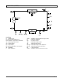
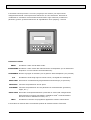
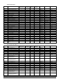
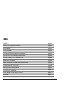
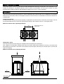
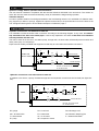
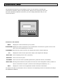
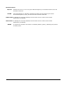
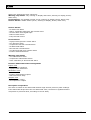
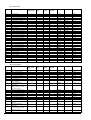
manuale di installazione, uso e manutenzione
Performo SR SR-LN
installation, operation and maintenance manual
Refrigeratori d’acqua condensati ad aria - air cooled
water chillers
IC_PERF SR SR-LN_MANUAL_A4
1
31-05-2007, 11:06
MANUALE TECNICO
norme di sicurezza
installazione
uso e manutenzione
AVVERTENZE GENERALI
Il presente manuale fa parte, assieme allo schema elettrico, al manuale del microprocessore e agli allegati specifici per modello, della documentazione fornita a corredo
della macchina. Il tutto deve essere conservato con cura e messo a disposizione
dell'operatore per ogni ulteriore consultazione.
Tutti gli interventi di manutenzione ordinaria e straordinaria devono essere eseguiti,
nel rispetto delle norme di sicurezza, da personale abilitato.
ser ie : P ERFO RMO S R - SR LN
cod. : MTPE00
rev. : I-06-07
SOMMARIO
SICUREZZA
pag. 3
RICEVIMENTO E IMMAGAZZINAGGIO
pag. 4
MOVIMENTAZIONE
pag. 4
POSIZIONAMENTO
pag. 5
INSTALLAZIONE : collegamenti idraulici
pag. 5
INSTALLAZIONE : collegamenti elettrici
pag. 6
PRIMO AVVIAMENTO - FUNZIONAMENTO
pag. 6
SOSTA INVERNALE
pag. 8
MANUTENZIONE : ordinaria e straordinaria
pag. 8
SMANTELLAMENTO UNITA'
pag. 8
SCHEMA FRIGORIFERO
pag. 9
CIRCUITO IDRAULICO
pag. 10
SISTEMA DI CONTROLLO
pag. 11
ALLARMI
pag. 13
2
SI CUREZZA
La macchina è stata progettata in modo da ridurre al minimo i rischi per la sicurezza delle persone che con essa
andranno ad interagire. In sede di progetto non é stato tecnicamente possibile eliminare completamente le cause di rischio. Pertanto è assolutamente necessario fare riferimento alle prescrizioni di seguito riportate.
Accesso all'unità
L'accesso all'unità una volta che è stata installata, deve essere consentito solamente a operatori e tecnici abilitati.
Per operatore si intende una persona autorizzata dal proprietario della macchina a compiere operazioni sulla
stessa (in accordo con quanto riportato nel presente manuale). Per tecnico si intende una persona autorizzata
dalla VENCO o in subordine sotto la sua completa responsabilità da un distributore VENCO, a compiere operazioni sulla macchina. Per proprietario della macchina si intende il legale rappresentante della società, ente o
persona fisica proprietaria dell'impianto in cui è installata la macchina VENCO. Egli é responsabile del rispetto
di tutte le norme di sicurezza indicate dal presente manuale e dalla normativa vigente.
Qualora per la natura del luogo di installazione non possa essere impedito l'accesso alla macchina da parte di
estranei, deve essere prevista una zona recintata attorno alla macchina ad almeno 1,5 metri di distanza dalle
superfici esterne, all'interno della quale possono operare solo operatori e tecnici.
Gli operatori o tecnici devono operare sulla macchina con un opportuno abbigliamento antinfortunistico (scarpe,
guanti, elmetti ecc.) e con opportuni utensili.
Rischi residui
L'installazione, l'avviamento, lo spegnimento, la manutenzione della macchina devono essere tassativamente
eseguiti in accordo con quanto riportato nella documentazione tecnica del prodotto e comunque in modo che
non venga generata alcuna situazione di rischio. I rischi che non é stato possibile eliminare in fase di progettazione sono riportati nella tabella seguente.
parte considerata
rischio residuo
modalità
batteria di scambio termico
piccole ferite da taglio
contatto
griglia ventilatore e ventilatore lesioni
interno unità :
compressore e tubo di
mandata
interno unità :
parti metalliche e cavi
elettrici
esterno unità :
zona circostante unità
ustioni
intossicazioni, folgorazione, ustioni gravi
intossicazioni, ustioni
gravi
inserimento di oggetti
appuntiti attraverso la
griglia mentre il ventilatore sta funzionando
contatto
precauzioni
evitare il contatto, usare
guanti protettivi
non infilare oggetti di alcun tipo dentro la griglia dei ventilatori e non appoggiare oggetti sopra le griglie
evitare il contatto, usare
guanti protettivi
difetto di isolamento cavi alimentazione a monte del quadro elettrico
dell'unità; parti metalliche in tensione
protezione eletttrica adeguata
della linea alimentazione;
massima cura nel fare il collegamento a terra delle parti
metalliche
incendio a causa corto
circuito o surriscaldamento della linea alimentazione a monte del
quadro elettr.dell'unità
sezione dei cavi e sistema di
protezione della linea alimentazione elettrica conformi alle
norme vigenti
3
RI CEVI MENTO E I MMAGAZZI NAGGI O
Controllare, all'atto del ricevimento, che il materiale non abbia subito danni e che corrisponda a quanto indicato
nel documento di accompagnamento. Eventuali danni, o situazioni di consegna incompleta devono essere tempestivamente segnalati. Il gruppo potrà essere immagazzinato in locali protetti dagli agenti atmosferici con temperature da -20°C a massimo +55°C.
MOVI MENTAZI ONE
Le unità possono essere movimentate sia con carrelli elevatori che con gru. Bisogna prestare particolare attenzione a non danneggiare, durante la movimentazione, la batteria di condensazione. Fare riferimento ai pesi riportati negli allegati. Si consiglia la movimentazione della macchina imballata.
Sollevamento con carrello elevatore
Se si usa un carrello elevatore, assicurarsi prima di ogni cosa che sia di portata adeguata e che le forche siano
lunghe almeno 1300 mm. L'unità deve essere sollevata posizionando le forche del carrello secondo le indicazioni riportate nella figura seguente. Assicurarsi che l'unità sia in perfetto equilibrio stabile.
1000
Le forche del carrello
devono sporgere di
almeno 50 mm.
Sollevamento con gru
Deve essere effettuato secondo lo schema in basso seguendo le istruzioni riportate.
Usare un bilancino o delle barre divaricatrici, corde di adeguata portata (non catene), tubi di diametro 42 mm
(1" 1/4) che dovranno essere infilati nei fori predisposti nel basamento della macchina; bloccare le estremità
dei tubi con spine e copiglie evitando che le corde si sfilino.
Assicurarsi che l'unità sia in perfetto equilibrio stabile.
A
spina
spina
B
tubo ø60 mm
4
POSI ZI ONAMENTO
Spazio di rispetto per il funzionamento e la manutenzione
L' unità deve essere installata rispettando gli spazi tecnici riportati negli allegati. Il piano su cui poggia l'unità deve essere livellato e robusto adatto a sopportarne il peso durante il funzionamento.
Antivibranti
Al fine di evitare trasmissione di vibrazioni alla struttura portante è opportuno installare negli appositi fori ricavati
nel basamento dell'unità dei supporti antivibranti (in gomma, forniti come accessorio opzionale). Il montaggio
degli antivibranti è evidenziato nello schema riportato negli allegati.
I NSTALLAZI ONE
Collegamenti idraulici
Si consiglia di effettuare il collegamento idrico del refrigeratore in accordo con lo schema seguente. In particolare è assolutamente necessario installare sulla tubazione di ingresso un filtro contro le eventuali impurità contenute nell'acqua. La mancata installazione di detto filtro comporta il decadimento della garanzia
Le tubazioni devono essere adeguatamente installate e sostenute cosicchè esse non vadano a caricare gli
attacchi sull'unità. Il kit idrico incorporato é formato da: pompa di circolazione, valvole sfiato aria, pressostato
differenziale. Se l'unità è senza kit idrico è necessario installare una pompa, un serbatoio accumulo coimbentato, un vaso espansione.
VS
RC
M
F
VS
P
SE
T
GA
FA
VI
VI
SA
Refrigeratore
M
VS
INGRESSO ACQUA
T
GA
VI
USCITA ACQUA
DISPOSITIVI DA INSTALLARE A CURA
DELL'INSTALLATORE.
RS
RC
M
T
FA
Refrigeratore
con kit idrico
incorporato
M
F
VS
GA
VS
VI
INGRESSO ACQUA
T
GA
VI
USCITA ACQUA
DISPOSITIVI DA INSTALLARE A CURA
DELL'INSTALLATORE.
RS
M = manometro
RC = rubinetto di scarico
RS = rubinetto di scarico
VS = sfiato aria
FA = filtro acqua
GA = giunto antivibrante
T = termometro
VI = valvola intercettazione
F = flussostato esterno
P = pompa
SE = vaso espansione
SA = serbatoio accumulo
5
Collegamenti elettrici
Nei disegni dimensionali riportati negli allegati è indicata la posizione prevista per l'ingresso dei cavi di alimentazione. Per accedere al quadro elettrico e quindi alla morsettiera di alimentazione é necessario smontare il
pannello alto frontale. Per il dimensionamento della linea di alimentazione fare riferimento ai valori di potenza e
corrente riportati nella tabella degli allegati. Lo schema elettrico della macchina si trova all'interno del vano compressore assieme al resto della documentazione a corredo.
E' necessario porre particolare attenzione ai seguenti punti:
- i collegamenti elettrici devono essere eseguiti da personale qualificato;
- i cavi di alimentazione devono essere protetti a monte contro gli effetti del cortocircuito e del sovraccarico da
un dispositivo idoneo conforme alle leggi vigenti;
- la sezione dei cavi deve essere commisurata alla taratura del sistema di protezione a monte e deve tenere
conto di tutti i fattori che la possono influenzare (temperatura, tipo di isolante, lunghezza, ecc.);
- è molto importante che il collegamento alla rete di terra sia effettuato con la massima cura.
- verificare il tipo di alimentazione che puo' essere trifase o trifase con neutro.
Nella morsettiera del quadro elettrico sono previsti due coppie di morsetti (contatti puliti): una é per l'allarme generale a distanza, l'altra é per l'ON OFF remoto (vedi schema elettrico).
PRI MO AVVI AMENTO O AVVI AMENTO DOPO UNA LUNGA SOSTA - FUNZI ONAMENTO
Prima di procedere all'avviamento del refrigeratore é necessario effettuare controlli preliminari della parte elettrica, idraulica e frigorifera. Almeno 12 ore prima di avviare l'unità deve essere accesa la resistenza elettrica
del compressore per far evaporare tutto il refrigerante presente nell'olio.
Cont r ol l i pr el i mi nar i - par t e el et t r i ca
Prima di effettuare i controlli di cui al presente paragrafo è necessario assicurarsi che la linea di alimentazione
elettrica dell'unità sia sezionata a monte della stessa. Assicurarsi che il dispositivo di sezionamento sia lucchettato o che sulla maniglia di azionamento sia applicato l'apposito cartello di avvertimento a non operare.
Ogni intervento va eseguito in mancanza di tensione procedendo come di seguito:
- togliere pannello frontale superiore;
- portare l'interruttore generale nella posizione "0" (OFF);
- aprire lo sportello del quadro elettrico;
- verificare che i cavi di alimentazione siano opportunamente dimensionati;
- verificare che il refrigeratore sia connesso all'impianto di terra;
- verificare il corretto serraggio delle viti che fissano i conduttori ai componenti elettrici presenti nel quadro in
modo da garantire unadeguato contatto;
- chiudere lo sportello del quadro elettrico.
A questo punto si può dare tensione alla macchina chiudendo il dispositivo di sezionamento della linea e portando l'interruttore generale della macchina nella posizione "1" (ON).
Controllare, con un voltmetro, i valori della tensione di fase fornti all'unità. Il valore della tensione di alimentazione deve essere 400 V +/- 10 %. Determinare la tensione media di fase (RS+ST+RT)/3 e la differenza percentuale fra ciascuna delle tensioni di fase e questo valore medio. La differenza massima non deve essere superiore al 3 %. Una variazione maggiore annulla la garanzia.
ESEMPIO:
R-S= 397V ; S-T= 406V ; R-T= 395V
media dei valori : (397+406+395) / 3 = 399,3
differenza percentuale : (406-397) / 399,3 x 100 = 2,25 %
(406-395) / 399,3 x 100 = 2,75
(397-395) / 399,3 x 100 = 0,5 %
6
Cont r ol l i pr el i mi nar i - par t e i dr aul i ca
- Controllare il corretto collegamento fra gli attacchi idrici della macchina e le tubazioni dell'impianto;
- controllare che le valvole di intercettazione del circuito idraulico siano aperte;
- controllare che l'impianto sia carico;
sfiatare tutta l'aria dall'impianto;
- controllare, durante il funzionamento, che la pompa di circolazione sia funzionante e che il senso di rotazione
della stessa sia in senso orario (vista difronte alla calotta copriventola);
- controllare che la portata d'acqua corrisponda a quella di progetto, assicurarsi che sia garantita sempre una
portata d'acqua costante.
Cont r ol l i pr el i mi nar i - par t e f r i gor i f er a
Controllare visivamente l'integrità dei vari componenti del circuito frigorifero.
Sui compressori assicurarsi che il livello dell'olio lubrificante sia a circa metà dell'apposito spioncino.
Av v i ament o
Dopo aver eseguito i controlli preliminari dell'unità, premere il tasto "ON/OFF" sul terminale del microprocessore. Il led "ON/OFF" diventerà verde e l'unità si avvierà.
NOTA IMPORTANTE : nell'unità è installato il compressore bivite. E' molto importante controllare il senso di rotazione del compressore. Se alimentato con la sequenza fasi sbagliata gira in senso contrario. In
tal caso è molto rumoroso e rischia di danneggiarsi: invertire immediatamente le fasi. Per un
controllo piu' preciso del senso di rotazione, collegare attraverso le apposite prese di pressione un
gruppo manometri e verificare che le pressioni siano esatte.
Funzi onament o a r egi me
Il sistema di controllo a microprocessore del refrigeratore regolerà la potenza frigorifera della macchina (accensione, spegnimento del compressore) in dipendenza del carico termico dell'impianto; controllare le temperature
di ingresso e uscita acqua: la differenza tra tali temperature non deve superare il limite massimo di circa 7°C.
Una differenza di temperatura maggiore è sintomo di scarsa portata d'acqua (rispetto al valore nominale) o presenza di aria nell'impianto.
Spegni ment o e accensi one
Per spegnere temporaneamente l'unità premere il tasto "ON/OFF" della tastiera microprocessore.
Per lunghi periodi di fermata sezionare la macchina agendo sull'interruttore generale del quadro elettrico.
7
SOSTA I NVERNALE
Se l'impianto idraulico è stato caricato con acqua è necessario provvedere alla sua evacuazione a fine stagione estiva per evitare la formazione di ghiaccio durante l'inverno. Se l'impianto è stato caricato con soluzione
antigelo l'operazione non deve essere effettuata. Prima dell'inizio della stagione fredda è necessario verificare
con un densimetro la concentrazione di glicole della miscela, rabboccando il circuito se necessario.
MANUTENZI ONE
Manut enzi one or di nar i a
La manutenzione ordinaria consiste in semplici operazioni che si consiglia di eseguire con cadenza mensile
procedendo come segue:
- verificare che il cavo elettrico di alimentazione della macchina non presenti alterazioni che ne compromettano
l'isolamento;
- verificare il corretto serraggio delle viti che fissano i conduttori ai componenti elettrici presenti nel quadro elettrico in modo da garantire un corretto collegamento elettrico; lo stesso dicasi per i collegamenti di messa a terra.
- controllare che non ci siano perdite nel circuito idraulico;
- controllare, durante il funzionamento del compressore le pressioni di mandata e aspirazione. E' necessario rimuovere il pannello del vano compressore e collegarsi con i manometri sulle opportune prese di pressione predisposte nel circuito frigorifero. Questa operazione deve necessariamente essere effettuata da personale abilitato.
Manut enzi one st r aor di nar i a
La manutenzione straordinaria consiste in operazioni che si rendono necessarie a seguito di anomalie di funzionamento. Rientrano in questi casi:
lo scarico del refrigerante, la carica di refrigerante, il rabbocco d'olio, la sostituzione del filtro deidratore, la messa in vuoto dei circuiti, configurazione del controllo. Queste operazioni devono essere eseguite tassativamente
da personale abilitato.
SMANTELLAMENTO DELL’ UNI TA’
La macchina è stata progettata e costruita per garantire un funzionamento continuativo. La durata di alcuni
componenti principali, ad esempio il compressore, dipende dalla manutenzione a cui è stato sottoposto.
In caso di smantellamento dell'unità, l'operazione dovrà essere eseguita da personale frigorista specializzato.
Il fluido frigorigeno e l'olio lubrificante contenuti nel circuito dovranno essere recuperati, in accordo con le norme vigenti nel Vostro Paese.
8
SCHEMA FRI GORI FERO
CN
F
VC
IL
VC
VL
C
PA
RC
M
~
Tp
St
VC
VC
EV
EVE
Tp
Drv Tp
LEGENDA
C
compressore
PA pressostato di alta press.
EVE valvola di espansione elettronica
VC attacchi gas di servizio
CN condensatore
EV evaporatore
PD pressostato differ. (lato acqua)
VL ventilatori
F
filtro deidratore
Drv St
PD
VC
VSLP
IL
RC
Tp
St
Drv Tp
Drv St
valvola di sicurezza di bassa pressione
indicatore di liquido
resistenza carter
trasduttore di pressione
sonda di temperatura
trasduttore di pressione del driver
sonda di temperature del driver
RL
r ubi net t o l i qui do
VSHP
valvola di sicurezza di alta pressione
9
CIRCUITO IDRAULICO
ingresso acqua
PD
VA
P
VS
uscita acqua
FA
EV
SE
LEGENDA
FA
VA
VS
PD
filtro acqua (a cura del cliente)
valvola di sicurezza (3 bar)
valvola sfiato aria
p r es sostato differenziale
10
SE
P
EV
vaso di espansione
pompa
ev apo r ato re
SISTEMA DI CONTROLLO
Il terminale utente previsto è con LCD (4 righe per 20 colonne) e di tipo esterno
collegato alla scheda a microprocessore attraverso un cavo telefonico. Permette di
visualizzare le condizioni di funzionamento dell'unità in ogni momento, modificare i
parametri, gestire gli allarmi attraverso la segnalazione visiva (display) e sonora
Terminal
menu
I/O
?
info
on/off
set
alarm
prog.
enter
Pulsanti di utilizzo
MENU
Visualizza i valori rilevati dalle sonde.
ASSISTENZA Visualizza i valori relativi alla manutenzione dei dispositivi (ore di utilizzo del
dispositivo e reset contaore di funzionamento).
STAMPANTE Accede al gruppo di maschere per la gestione della stampante (ove prevista)
I/O
Visualizza lo stato degli ingressi e delle uscite, sia digitali che analogiche.
OROLOGIO Permette la visualizzazione/programmazione dell'orologio (se presente).
SETPOINT
Consente l'impostazione del set point.
PROGRAM
Consente l'impostazione dei vari parametri di funzionamento (protezioni,
soglie, etc…).
MENU+PROG Premendo contemporaneamente questi tasti si entra nella configurazione
della macchina (numero di dispositivi collegati al pCO1, programmazione
dei fondo scala e calibrazione sonde, etc…).
INFO
Visualizza la versione del programma applicativo ed altre informazioni.
I led a fianco di ciascun tasto si illuminano quando la relativa funzione è attivata.
11
Tasti esterni
ON/OFF
Consente l'accensione e lo spegnimento della macchina. Il LED verde che
illumina il tasto indica se l'accensione è stata effettuata.
ALARM
E' utilizzato per la visualizzazione su display degli allarmi, per il loro
rirpistino manuale e per la tacitazione del cicalino. Se il tasto è illuminato
(colore rosso) significa che è stato rilevato almeno un allarme.
FRECCIA SU Per la gestione delle maschere su display e per l'impostazione dei valori dei
parametri di controllo (non retroilluminato).
FRECCIA GIU' Per la gestione delle maschere su display e per l'impostazione dei valori dei
parametri di controllo (non retroilluminato).
ENTER
12
Per la conferma dei dati impostati. Il tasto è costantemente retroilluminato
(luce gialla) per indicare la presenza dell'alimentazione.
ALLARMI
Gli allarmi sono divisi in tre categorie:
Allarmi di sola segnalazione: sola segnalazione a display e buzzer, segnalazione su display,
buzzer, relè di allarme.
Allarmi di circuito: disattivano solo il circuito relativo, segnalazione su display, buzzer, relè
di allarme.
Allarmi gravi: disattivano l'intero sistema, segnalazione su display, buzzer, relè di allarme.
Allarmi gravi
- Allarme mancanza flusso acqua
- Allarme antigelo evaporatore a riarmo manuale
- Allarme grave da ingresso digitale
- Allarme monitore di fase
- Termico pompa
Allarmi di circuito
- Allarme alta pressione/pressostato
- Allarme bassa pressione
- Allarme termico compressore
- Allarme differenziale olio
- Allarme termico ventilatore
- Allarme unità sconnesse dalla rete
- Allarme differenziale pressioni
Allarmi di sola segnalazione
- Allarme manutenzione unità
- Allarme manutenzione compressori
- Allarme schedina orologio guasta o sconnessa
Gestione allarme differenziale pressioni
Ingressi utilizzati
- Trasduttore di bassa pressione
- Trasduttore di alta pressione
Parametri utilizzati
- Abilitazione allarme
- Set point differenziale pressioni
- Ritardo attivazione allarme
Uscite utilizzate
- Relè di allarme generale
- Tutte le uscite relative ai compressori
Descrizione funzionamento
L'allarme si basa sul differenziale tra le letture delle sonde di alta e bassa pressione. Se
questo scende al di sotto del valore di differenziale impostato, viene segnalato
l'allarme e spento il compressore, secondo il ritardo impostato.
13
Tabella allarmi pCO
Codice
Descrizione Allarme
OFF
Compressori
Allarme Grave
*
Allarme Monitore di Fase
*
Termico Pompa Evaporatore
*
Termico Pompa Condensatore
*
Flussostato Evaporatore
*
Flussostato Condensatore
*
Allarme Antigelo
*
Unità 1 Offline
*
Unità 2 Offline
*
Unità 3 Offline
*
Unità 4 Offline
*
Termico Compressore
*
Pressostato Differenziale Olio
*
Basso Differenziale Pressioni
*
Pressostato Bassa Pressione
*
Pressostato Alta Pressione
*
Bassa Pressione Trasduttore
*
Alta Pressione Trasduttore
*
Termico Ventilatore 1
Termico Ventilatore 2
Alta Tensione
Alta Corrente
Manutenzione Pompa Evap.
Manutenzione Pompa Cond.
Manutenzione Compressore
Sonda Guasta B1
*
Sonda Guasta B2
*
Sonda Guasta B3
Sonda Guasta B4
Sonda Guasta B5
Sonda Guasta B6
Sonda Guasta B7
Sonda Guasta B8
Scheda Orologio 32KB
Guasta
011
012
018
019
013
014
031
001
002
003
004
020
015
032
017
016
034
033
021
022
036
037
051
052
053
060
061
062
063
064
065
066
067
041
OFF
Ventilatori
*
*
*
*
*
*
*
*
*
*
*
OFF
Pompa
*
*
*
*
*
*
*
*
*
*
OFF
Sistema
*
*
*
*
*
*
*
*
*
*
*
*
*
*
*
*
*
*
*
*
*
*
*
Riarmo
Manuale
Manuale
Manuale
Manuale
Manuale
Manuale
Manuale
Automatico
Automatico
Automatico
Automatico
Manuale
Manuale
Manuale
Manuale
Manuale
Manuale
Manuale
Manuale
Manuale
Manuale
Manuale
Manuale
Manuale
Manuale
Automatico
Automatico
Automatico
Automatico
Automatico
Automatico
Automatico
Automatico
Manuale
Ritardo
Impostabile
Impostabile
50 / 30 s
50 / 30 s
50 / 30 s
50 / 30 s
Impostabile
Impostabile
Impostabile
10 s
10 s
10 s
10 s
10 s
10 s
10 s
10 s
Segnalazione
Mst/Slv
Mst/Slv
Mst
Mst
Mst/Slv
Mst/Slv
Mst/Slv
Slv
Mst
Mst
Mst
Mst/Slv
Mst/Slv
Mst/Slv
Mst/Slv
Mst/Slv
Mst/Slv
Mst/Slv
Mst/Slv
Mst/Slv
Mst/Slv
Mst/Slv
Mst
Mst
Mst/Slv
Mst
Mst/Slv
Mst/Slv
Mst/Slv
Mst/Slv
Mst/Slv
Mst/Slv
Mst/Slv
Mst/Slv
Allarmi delle schede Driver
Codice
101
102
103
104
105
106
107
108
109
110
111
201
202
203
204
205
206
207
208
209
210
211
14
Descrizione Allarme
OFF
Compressori
Errore sonda driver 1
*
Errore eeprom driver 1
*
Errore stepper motore driver 1
*
Errore batteria driver 1
*
Alta pressione sul driver 1
Bassa pressione sul driver 1
Basso super-heat driver 1
*
Valvola non chiusa durante
*
spegnimento driver 1
Alta temperatura di
aspirazione driver 1
Attesa per errore
*
eeprom/ricarica batteria o
valvola aperta driver 1
Lan sconnessa driver 1
*
Errore sonda driver 2
*
Errore eeprom motor driver 2
*
Errore stepper motore driver 2
*
Errore batteria driver 2
*
Alta pressione sul driver 2
Bassa pressione sul driver 2
Basso super-heat driver 2
*
Valvola non chiusa durante
*
spegnimento driver 2
Alta temperatura di
aspirazione driver 2
Attesa per errore
*
eeprom/ricarica batteria o
valvola aperta driver 2
Lan sconnessa driver 2
*
OFF
Ventilatori
OFF
Pompa
OFF
Sistema
Riarmo
Ritardo
Segnalazione
Manuale
Manuale
Manuale
Manuale
Manuale
Manuale
Manuale
Manuale
Mst
Mst/Slv
Mst/Slv
Mst/Slv
Mst/Slv
Mst/Slv
Mst/Slv
Mst/Slv
Manuale
Mst/Slv
Manuale
Mst/Slv
Manuale
Manuale
Manuale
Manuale
Manuale
Manuale
Manuale
Manuale
Manuale o
Mst/Slv
Mst/Slv
Mst/Slv
Mst/Slv
Mst/Slv
Mst/Slv
Mst/Slv
Mst/Slv
Mst/Slv
Manuale
Mst/Slv
Manuale
Mst/Slv
Manuale
Mst/Slv
TECHNICAL MANUAL
safety standars
installation
use and maintenance
GENERAL INSTRUCTIONS
Together with the wiring diagram, the microprocessor manual and the specific enclosures for the model, this manual is a part of the documentation supplied with the machine.
This must be kept carefully and be available to the operator for future reference.
All ordinary and extraordinary maintenance must be carried out by authorised personnel
in compliance with the safety regulations.
s er ies : PERF ORM O SR - SR L N
cod. : MTPE00
rev. : E -06-07
INDEX
SAFETY
page 3
RECEPTION AND STORAGE
page 4
MOVEMENT
page 4
POSITIONING
page 5
INSTALLATION: hydraulic connections
page 5
INSTALLATION: electrical connections
page 6
INITIAL START-UP - OPERATION
page 6
WINTER STORAGE
page 8
MAINTENANCE: ordinary and extraordinary
page 8
DISPOSING OF THE UNIT
page 8
REFRIGERATION DIAGRAM
page 9
WATER KIT DIAGRAM
page 10
ELECTRONIC CONTROL SYSTEM
page 11
ALARMS
page 13
2
SA F E T Y
The machine has been designed to minimize hazards for the safety of persons dealing with it. When planning the
machine it was not technically possible to eliminate all risks entirely. Therefore, it is absolutely essential to follow
the instructions set down below.
Access to the unit
Once the unit has been installed, only authorised operators and technicians must be allowed access to it. By operator we intend a person authorised by the owner of the machine to carry out operations using this machine (in
compliance with the instructions set down in this manual). By technician we intend a person authorised by VENCO,
or a subordinate under the direct responsibility of a VENCO distributor, to carry out operations on the machine. By
owner of the machine we intend the legal rapresentative of the company, body or individual owning the system in
which the VENCO machine has been fitted. This person is responsible for compliance with all the safety regulations set down in this manual and in the laws in force. Should it be impossible, owing to the place in which the machine is installed, to prevent strangers from gaining access to the machine, a fenced-in area must be provided
around the machine at to less than 1,5 metres from the outer surface, within which only operators and technicians
may gain access.
When working on the machine, operators or technicians must wear protective clothing (footwear, gloves, helmets,
etc.) and use suitable tools.
Remaining risks
Installation, start-up, shut-down and maintenance on the machine must be carried out in strict compliance with the
techincal documentation of the product and in any case, in such as way as no hazardous situations are created.
Hazards that were impossible to eleminate during planning are set down in the table below.
part
remaining risk
method
precautions
heat exchange battery
small cuts
contact
avoid contact, use protective
gloves
fan grille and fan
lesions
inside the unit :
compressor and delivery pipe
burns
inside the unit :
metal parts and electric wires intoxication, shock,
serios burns
outside the unit :
areas around the unit
intoxication, serios
burns
introducing sharp ob- do not introduce objects of any
jects through the grille type through the ventilator grilwhile the fan is opera- les and do not lay anything on
ting
the grilles
contact
avoid contact, use protective
gloves
faults in power cable insulation upstream of the
unit switchboard; live
metal parts
appropriate electrical protection of the power line, extreme
care over earth connections of
metal parts
fires caused by short-circuit or overheating of
the power line upstream
of the unit switchboard
cable section and protective
system of the power line in
compliance with the standars
in force
3
R E C E P T I O N A N D S T O R AG E
Check upon delivery that the goods have not been demaged and that they correspond to the information in the
waybill. Any damage or incomplete deliveries must be quickly communicated. The unit may be stored in a place
protected from weather conditions with temperature ranging from -20°C to +55°C maximum.
M OV E M E N T
Units can either be moved by lift trucks or cranes. Particular care must be taken not to damage the condesation
battery during movement. Refer to the weights set down in the enclosures. It is advisable to move the machine while still packed.
Lifting with lift truck
If using a lift truck, firstly check that the capacity is appropriate and the forks are at least 50 mm in lenght. The unit
must be lifted with the forks of the truck positioned according to the indications shown in the figure below.
Make sure that the unit is perfectly balanced
1000
LLe
ift fforc
orkshe
mdel
ust carr
stickello
out
dev
ab
ouono
t 50spo
mmrgere di
almeno 50 mm.
Lifting with a crane
This must be carried out according to the diagram below and folling the instructions:
Use: a balance or forked bars; suitably sturdy rope (not chains), pipes with a diameter of 42 mm (1"1/4) which must
be threaded into the holes in the base of the machine; block the pipe ends with pins and split pins, to prevent the
ropes from slipping
Make sure that the unit is perfectly balanced
A
pinna
spi
spi
pina
n
B
ttub
ubeodø60
. 60mm
mm
4
P O S I T I ON I N G
Spaces to comply with for operation and maintenance
The unit must be installed in compliance with the technical distances indicated in the enclosures. The surface on
which the unit rests must be level and sufficently sturdy to withstand the weight during operation.
Vibration dampers
In order to prevent vibration from being transmitted to the load-bearing structure it is advisable to fit vibration damping supports (in rubber or springs, supplied as optional accessories) in the special holes found in the base of the
unit. A diagram showing how to fit the vibration dampers is included to page 4.
I N S TA L L A T I O N
Hydraulic connections: unit with built-in water kit
It is advisable to make the chiller water connection according to the following diagram. In any case, it is absolutely essential to fit a filter to the intake pipe to remove any impurities in the water. If this filter is not fitted the
warranty shall be null and void.
The built-in water kit is formed of: circulation pump, storage tank, air bleed valve, differential pressure switch and
safety valve (only on heat pumps).
Pipes must be suitably insulated and supported so that they do not burden the machine connections.
RC
M
T
GA
FA
Chiller with
built-in water kit
M
F
VS
VI
VS
WA TER INT AKE
T
GA
VI
WA TER DEL IVER Y
DEVI CES TO B E INS TALLED
B Y AN INS T ALLER
RS
Hydraulic connections: unit without built-in water kit
In addition to the above, a pump, insulated storage tank and expansion vessel must also be fitted (see figure below).
VS
RC
M
F
VS
P
T
FA
GA
VI
SE
VI
SA
Chiller
M
VS
WA TER INTAKE
T
GA
VI
WA TER DELIVER Y
DEVI CES TO BE INSTALLED
B Y AN INST ALLER
RS
M = gauge
RC = load cock
RS =discharge cock
VS = air bleed valve
FA = water filter
GA =vibration damping joint
T = thermometer
VI = on-off valve
F = external flowswitch
P = pump
SE = expansion vessel
5
Electrical connections
In the overall dimensions drawings icluded in the enclosures the envisaged position for power cable ingress is indicated. To gain access to the switchboard and terminal block the top front doors of the compressors housing must
be open. For power line dimensions refer to the power and current values indicated in the table "technical data".
The wiring diagram of the machine can be found inside the switchboard together with the rest of the documents
provided.
Particular care must be taken over the folling points:
- the electrical connections must be performed by qualified personel;
- the power cables must be protected upstream against short circuits and overloading by a suitable device in compliance with the laws in force;
- the cross-section of cables must be proportionate to the calibration of the protective system upstream and musttake into consideration all factors that could be on influence (temperature, type of insulation, length, etc.);
- it is extremely important to take great care over the connection to the earth line;
- check the type of power supply, which can either be three-phase or three-phase with neutral.
Two pairs of terminals (clean contacts) have been provided for in the terminal block of the switchboard: one for the
general remote alarm, the other for remote ON/OFF (see wiring diagram).
I N I T I A L S TA R T - U P O R S TA R T - U P A F T E R A L O N G P E R I O D O F D I S U S E - O P E R A T I O N
Before starting up the chiller, some preliminary checks on the electrical, hidraulic and refrigerating parts must be
carried out.
Energize the unit 12 hour before the start up to switch on the electrical heater of the compressor to
evaporate all the refrigerant in the oil.
Preliminary checks - electrical part
Before performing the checks in this paragraph, make sure that the power line is disconnected upstream of the
unit. Check that the knife switch is padlocked or that the specific notice warning not to use it is affixed to the handle. All operations are carried out with the power disconnected, proceeding as follows:
- remove the top front panel;
- position the main switch to "0" (OFF);
- open the door of the switchboard;
- check that power cables are of the correct dimensions;
- check that the refrigerator is connected to the earth system;
- check that the screws fastening the wires to the electrical components in the board are clamped tightly to ensure
correct contact;
- close the switchboard panel.
The machine can now be reconnected to the power supply by closing the knife switch on the line and positioning
the main switch of the machine to "1" (ON).
Using a voltmeter, check the phase voltage values supplied to the unit. The voltage value must be 400V ± 10%.
Establish the average phase voltage (RS+ST+RT)/3 and the difference in percentage between each of the phase
voltages and this average value. The maximum difference must not exceed 3%. Whit any greater variations the
warranty shall be deemed null and void.
EXAMPLE:
R-S= 397V ; S-T= 406V ; R-T= 395V
average value : (397+406+395) / 3 = 399,3
percentage difference : (406-397) / 399,3 x 100 = 2,25 %
(406-395) / 399,3 x 100 = 2,75 %
(397-395) / 399,3 x 100 = 0,5 %
6
Preliminary checks - hydraulic system
- Check that the water connections of the machine and the sistem pipes are connected correctly;
- check that the on-off valves of the hydraulic circuit are open;
- check that system is loaded;
- bleed all the air from the system;
- check during operation that the circulation pump is running and that it rotates clockwise (view from in front of the
fan cover).
- check that the water capacity corresponds to the project capacity, make sure that there is always a constant
flow of water.
Preliminary checks - refrigerating system
Inspect the various components of the refrigerating circuit to make sure they are in good condition.
Check that the level of lubrificating oil of the compressors is about halfway on the dedicated sight glass.
Starting up
After preliminary checks of the unit, push the ON/OFF botton in the therminal of the microprocessor. The led
become green and the unit will start.
IMPORTANT: in the unit is installed a twin screw semihermetc compressor. It is extremely important to
check the direction of rotation of compressors. If fed with an incorrect phase sequence they rotate in the
opposite direction. If this happens they are very noisy and could be subjected to damaged: invert the
phases immediately. For a more accurate check of the rotation direction, connect a gauge set to the
dedicated pressure intakes and check that pressures are correct.
Operating at the correct level
The microprocessor control system of the chiller will regulate the refrigerating capacity of the machine (compressor
start-up and shut-down) according to the thermal load of the system; check intake and delivery temperatures of the
water: the difference between these two temperatures must not exceed a maximum of about 7 °C. A greater difference in temperature is a sign of low water supply (compared to the rated value) or air in the system.
Shut-down and start-up
To temporarily shut-down units press the "ON/OFF" key on the microprocessor keyboard and/or open the remote
on/off contacts.
For long periods of disuse, switch off the machine using the main switch on the switchboard.
7
W I N T E R S TO R A G E
If the hydraulic system has been loaded with water, this must be emptied at the end of the summer season to
prevent ice from forming during the winter. If the system has been loaded with anti-freeze solution this is not necessary. Before the cold weather begins, check the concentration of glycol in the mixture with a densimeter, and
top up the circuit if necessary.
M A I N T E NAN C E
Ordinary maintenance
Ordinary maintenance consists of simple operations which should be carried out each month, proceeding as follows:
-check that the screws fastening the fans to the grille to the structure are clamped tightly;
- check the condensation batteries. To ensure correct heat exchange, these must be clean. Therefore, any airbor
ne dirt that has accumulated on the surface must be removed. Remove paper, leaves, etc., and clean the fins with
a jet of air. To prevent damaging the aluminium fins, the jet of air must be perpendicular to the surface of the bat
tery. Cleaning operations must be carried out extremely carefully, as the battery fins atre easily damaged (0,12
mm aluminium). In the event of damage to the fins, these must be repositioned by combing with the dedicated
tool. Wear protective gloves to perform any work on the batteries, as accidental contact with the fins can cause
small cuts;
- check that the power cable of the machine has no faults that could jeopardize insulation;
- check that the screws fastening the wires to the electrical components in the switchboard are clamped tightly to
ensure correct electrical connection; also check the earth connections;
- check that there are no leaks in the hydraulic circuit;
- check the delivery and suction pressure during compressor operation. This must be done by removing the panels
of the compressor housing and connecting gauges to the appropriate pressure intakes on the refrigerating circuits.
This operation must be carried out by authorised personnel;
- visual check of the compressor oil level pilot light.
Extraordinary maintenance
Extraordinary maintenance consists of operations that are made necessary by operating faults. These are:
draining off coolant, loading coolant, topping up oil, replacing the dehydrator filter, emptying the circuits, configuration of the control. These operations must ONLY be carried out by authorised personnel.
D I S P OS I N G O F T H E U N I T
The machine has been designed and manufactured to guarantee continual operation.The life-span of some of
the main components, such as the fan and compressor, depend upon the maintenance to which they are subjected.
If necessary, the unit must be disposed of by specialised refrigerating technicians.
The refrigerating fluid and lubrication oil contained in the circuit must be recovered, in compliance with the regulations in force in your country.
8
R E F R I G E R AT I O N D I AG R A M S
CN
F
VC
IL
VC
VL
PA
RC
C
M
~
Tp
St
VC
VC
EV
EVE
Tp
Drv Tp Drv St
PD
VC
LEGEND
C
PA
EVE
VC
CN
EV
PD
RL
F
comp r es so r
h i gh p r es s. p r es su r e s w i tch
e l ec tr on i c e x pans i on v al ve
se r v i ce gas connec tion
conden s er
ev apo r a to r
di f f . p r es su r e s w i tch ( w ate r s i ze)
f l u i t tap
deh y d r ato r f i l te r
IL
VL
VS LP
VS H P
RC
TP
ST
D r v Tp
D r v St
f l u i d i nd i ca to r
f an s
lo w p r es su r e s afe ty v al v e
H igh p r essu r e s afe ty v al ve
c r an ka se heate r
p r e s su r e t r a sduce r
tempe r atu r e p r obe
d r i v e r p r es su r e t r a sduce r
d r i v e r tempe r atu r e p r obe
9
W AT E R K I T D I AG R A M S
water inlet
PD
VA
P
VS
water outlet
FA
EV
SE
LEGEND
FA
VA
VS
PD
w ate r f i l te r (custome r ' s ac count)
s afe ty v al v e (3b ar )
ai r d i sch ar ge v al ve
di f f . p r es su r e s w i tch
10
SE
P
EV
e x pan s i on v e s se l
pump
ev apo r ato r
ELECTRONIC CONTROL SYSTEM
The specified terminal has an LCD display (4 lines over 20 columns) external type
connected by telephone cable to microprocessor. With the user terminal you can view
the unit's operating conditions at all times, you can modify parameters and you can
control the alarms.
Terminal
menu
I/O
?
info
on/off
set
alarm
prog.
enter
Functions of the buttons
MENU
Displays the values measured by the probes.
ASSISTENZA Display the values correspond. to the maintenance of the devices (operat. hours of the
device and reset operating hour counter).
STAMPANTE Accesses the group of screens for manging the printer (where featured).
I/O
Displays the status of the inputs and outputs, both digital and analogue.
OROLOGIO Used to display/set the clock (if present).
SETPOINT
Used to set the set point.
PROGRAM
Used to set the various operating parameters (protection devices, thresholds).
MENU+PROG Pressing these buttons at the same time enters the unit configuration mode (number of
devices connected to the pCO1, probe full scale setting and calibration, etc…).
INFO
Displays the version of the application software and other information.
The LEDs to the side of each button come on when the corresponding function is activated (according to
the application software).
11
External buttons
ON/OFF
ALARM
Switches the unit on or off. The green LED that lights up in the button shows if the unit
has been turned on.
Used for displaying or manually resetting the alarms and for silencing the buzzer.
If the button lights up (red), at least one alarm has been detected.
FRECCIA SU To manage the currently displayed screen and to set the values of the control
parameters (not backlit).
FRECCIA GIU' To manage the currently displayed screen and to set the values of the control
parameters (not backlit).
ENTER
12
To confirm the set data. The button is constantly backlit (yellow), indicating the presence
of mains power.
ALARMS
Alarms are divided into three categories:
Warning only alarms: only warning on display and buzzer, warning on display, buzzer,
alarm relay.
Circuit alarms: only disable relevant circuit, warning on display, buzzer, alarm relay.
Serious alarms: disable whole system, warning on display, buzzer, alarm relay.
Serious alarms
- No water flow alarm
- Alarm: evaporator antifreeze with manual reset
- Serious alarm from digital input
- Phase monitor alarm
- Pump thermal cutout
Circuit alarms
- High pressure/pressure switch alarm
- Low pressure alarm
- Compressor thermal overload alarm
- Oil differential alarm
- Fan thermal overload alarm
- Unit disconnected from network alarm
- Pressure differential alarm
Warning only alarms
- Unit maintenance alarm
- Compressor maintenance alarm
- Clock card faulty or disconnected alarm
Pressure differential alarm management
Inputs used
- Low pressure transducer
- High pressure transducer
Parameters used
- Enable alarm
- Pressure differential set point
- Alarm activation delay
Outputs used
- General alarm relays
- All compressor outputs
Description of operation
The alarm is based on the differential between high and low pressure probe readings.
If the differential drops below the set differential value, the alarm is signalled and the
compressor is powered down, according to the set delay.
13
pCO alarms table
Code
Alarm description
OFF
Compressor
s
Serious Alarm
*
Phase Monitor Alarm
*
Evaporator Pump thermal Cutout
*
Condenser Pump thermal Cutout
*
Evaporator Flow-switch
*
Condenser Flow-switch
*
Antifreeze Alarm
*
Unit 1 Offline
*
Unit 2 Offline
*
Unit 3 Offline
*
Unit 4 Offline
*
Compressor Thermal cutout
*
Oil Differential Pressure Switch
*
Low Pressure Differential
*
Low Pressure 2 Pressure-switch
*
High Pressure Pressure-switch
*
Low Transducer Pressure
*
High Transducer Pressure
*
Fan 1 Thermal cutout
Fan 2 Thermal cutout
High Voltage
High Current
Evap. Pump Maintenance
Cond. Pump Maintenance
Compressor Maintenance
B1 Probe Failed
*
B2 Probe Failed
*
B3 Probe Failed
B4 Probe Failed
B5 Probe Failed
B6 Probe Failed
B7 Probe Failed
B8 Probe Failed
32KB Clock Card Failed
011
012
018
019
013
014
031
001
002
003
004
020
015
032
017
016
034
033
021
022
036
037
051
052
053
060
061
062
063
064
065
066
067
041
OFF
Fans
OFF
Pump
*
*
*
*
*
*
*
*
*
*
*
*
*
*
*
*
*
*
*
*
*
OFF
System
*
*
*
*
*
*
*
*
*
*
*
*
*
*
*
*
*
*
*
*
*
*
*
Reset
Manual
Manual
Manual
Manual
Manual
Manual
Manual
Automatic
Automatic
Automatic
Automatic
Manual
Manual
Manual
Manual
Manual
Manual
Manual
Manual
Manual
Manual
Manual
Manual
Manual
Manual
Automatic
Automatic
Automatic
Automatic
Automatic
Automatic
Automatic
Automatic
Manual
Delay
Settable
Settable
50 / 30 s
50 / 30 s
50 / 30 s
50 / 30 s
Settable
Settable
Settable
10 s
10 s
10 s
10 s
10 s
10 s
10 s
10 s
Separation
Mst/Slv
Mst/Slv
Mst
Mst
Mst/Slv
Mst/Slv
Mst/Slv
Slv
Mst
Mst
Mst
Mst/Slv
Mst/Slv
Mst/Slv
Mst/Slv
Mst/Slv
Mst/Slv
Mst/Slv
Mst/Slv
Mst/Slv
Mst/Slv
Mst/Slv
Mst
Mst
Mst/Slv
Mst
Mst/Slv
Mst/Slv
Mst/Slv
Mst/Slv
Mst/Slv
Mst/Slv
Mst/Slv
Mst/Slv
Driver card alarms
Code
Alarm description
101
102
103
104
105
106
107
108
Diver 1 probe error
Diver 1 EEPROM error
Diver 1 stepped motor error
Diver 1 battery error
High pressure on driver 1
Low pressure on driver 1
Low super-heat
Valve not shut while driver 1
being disabled
Driver 1 high intake
temperature
standby due to EEPROM
/battery recharge / or open
valve error, driver 1
LAN disconnected, driver 1
Diver 2 probe status
Diver 2 motor EEPROM error
Diver 2 stepped motor error
Diver 2 battery error
High pressure on driver 2
Low pressure on driver 2
Low super-heat driver 2
Valve not shut while driver 2
disabled
Driver 2 high intake
temperature
standby due to EEPROM
/battery recharge / or open
valve error, driver 2
LAN disconnected, driver 2
109
110
111
201
202
203
204
205
206
207
208
209
210
211
14
OFF
Compressor
s
*
*
*
*
OFF
Fans
OFF
Pump
OFF
System
Reset
Delay
Separation
Manual
Manual
Manual
Manual
Manual
Manual
Manual
Manual
Mst
Mst/Slv
Mst/Slv
Mst/Slv
Mst/Slv
Mst/Slv
Mst/Slv
Mst/Slv
Manual
Mst/Slv
*
Manual
Mst/Slv
*
*
*
*
*
Manual
Manual
Manual
Manual
Manual
Manual
Manual
Manual
Manual or
Mst/Slv
Mst/Slv
Mst/Slv
Mst/Slv
Mst/Slv
Mst/Slv
Mst/Slv
Mst/Slv
Mst/Slv
Manual
Mst/Slv
*
Manual
Mst/Slv
*
Manual
Mst/Slv
*
*
*
*
iC Spa Via dell’Olmo
36014 Santorso (Vi) - Italy
tel. +39 0445 540147
fax +39 0445 540380
www.venco.net
[email protected]
IC_PERF SR SR-LN_MANUAL_A4
2
31-05-2007, 11:06
In un’ottica di miglioramento continuo e a fronte della costante azione di ricerca e sviluppo, Venco si riserva di modificare, anche senza preavviso, i dati tecnici riportati.
In the aim of further developments and product upgrade, Venco reserves the right to change the technical data without notice.