1
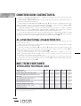
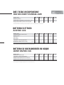
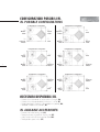
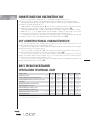
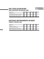
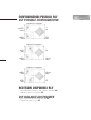
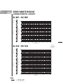
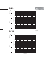
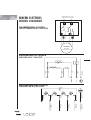
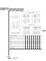
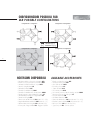
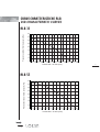
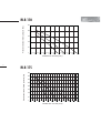
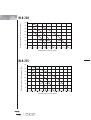
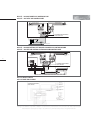
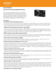
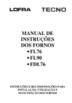
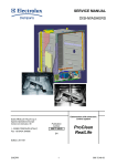
HEAT RECOVERY UNITS
TECHNICAL MANUAL
MANUALE TECNICO
INDICE
- Caratteristiche costruttive RL
............................................................................................................................... pag.
5
................................................................................................................................... pag.
5
..................................................................................................................................................... pag.
7
- Caratteristiche tecniche RL
- Dimensioni unità RL
- Configurazioni possibili RL
- Accessori disponibili RL
..................................................................................................................................... pag.
8
............................................................................................................................................. pag.
8
- Caratteristiche costruttive RLF
............................................................................................................................ pag.
9
................................................................................................................................ pag.
9
.................................................................................................................................................. pag.
11
- Caratteristiche tecniche RLF
- Dimensioni unità RLF
2
- Configurazioni possibili RLF
- Accessori disponibili RLF
................................................................................................................................. pag.
12
......................................................................................................................................... pag.
12
- Curve caratteristiche RL - RLF
- Schema elettrico RL - RLF
............................................................................................................................. pag.
13
...................................................................................................................................... pag.
17
........................................................................................................................... pag.
19
............................................................................................................................... pag.
20
................................................................................................................................................. pag.
21
- Caratteristiche costruttive RLB
- Caratteristiche tecniche RLB
- Dimensioni unità RLB
- Configurazioni possibili RLB
................................................................................................................................. pag.
22
- Accessori disponibili RLB
......................................................................................................................................... pag.
22
- Curve caratteristiche RLB
........................................................................................................................................ pag.
23
.................................................................................................................................................. pag.
27
- Schema elettrico RLB
CONTENTS
- Constructional characteristics RL
.................................................................................................................. pag.
5
................................................................................................................................... pag.
5
........................................................................................................................................................ pag.
7
- Technical specifications RL
- Unit dimensions RL
- Possible configurations RL
- Available accessories RL
.................................................................................................................................... pag.
8
......................................................................................................................................... pag.
8
............................................................................................................... pag.
9
................................................................................................................................ pag.
9
.................................................................................................................................................... pag.
11
- Constructional characteristics RLF
- Technical specifications RLF
- Unit dimensions RLF
- Possible configurations RLF
- Available accessories RLF
................................................................................................................................. pag.
12
...................................................................................................................................... pag.
12
- Characteristic curves RL - RLF
- Wiring diagram RL - RLF
............................................................................................................................ pag.
13
........................................................................................................................................... pag.
17
............................................................................................................... pag.
19
............................................................................................................................... pag.
20
.................................................................................................................................................... pag.
21
- Constructional characteristics RLB
- Technical specifications RLB
- Unit dimensions RLB
- Possible configurations RLB
................................................................................................................................. pag.
22
- Available accessories RLB
...................................................................................................................................... pag.
22
- Characteristic curves RLB
....................................................................................................................................... pag.
23
...................................................................................................................................................... pag.
27
- Wiring diagram RLB
➥
➥
3
UNITÀ RECUPERO
CALORE: RL - RLF
HEAT RECOVERY
UNITS: RL - RLF
4
CARATTERISTICHE COSTRUTTIVE RL
Le unità di recupero del calore tipo “RL”, uniscono la funzionalità e praticità dell’unità ventilante al sistema di recupero energetico.
Trovano largo impiego in locali pubblici, dove il fumo o l’affollamento di persone rendono indispensabile il rinnovo continuo dell’aria.
Sono prodotte in versione orizzontale (H) e verticale (V), con struttura in profilato estruso di alluminio e pannelli in lamiera zincata con rivestimento interno in materassino fonoassorbente (SP),
oppure pannello a doppio guscio coibentato internamente (DP).
I ventilatori sono centrifughi a doppia aspirazione, direttamente accoppiati a motori a 3 velocità
monofase 220 V - 50 Hz a rotore esterno. Il recuperatore di calore è di tipo statico a flussi incrociati con piastre in alluminio e i filtri sono a celle con setto sintetico, efficienza EU 4.
La cassonatura è realizzata con struttura in profilato estruso di alluminio e pannelli in lamiera
zincata con rivestimento interno in materassino fonoassorbente in polietilene (SP), oppure doppio
pannello in lamiera zincata con coibente interno in poliuretano espanso (DP).
RL CONSTRUCTIONAL CHARACTERISTICS
The “RL” heat recovery units combine the functionality and practicality of ventilating units with
energy recovery systems.
They have many applications in public premises, where the presence of smoke or crowds of people make continuous air change essential.
They are available in the horizontal (H) and vertical (V) versions, with an extruded aluminium section bar frame and galvanised plate panels, lined internally with a layer of acoustic insulation (SP), or
alternatively double layer panels with internal insulation (DP).
The dual intake centrifugal fans have directly-coupled, three-speed single-phase 220V/50Hz
motors with external rotor; the heat recovery unit is a static cross-flow system with aluminium plates
and cell filters with synthetic septum, efficiency EU 4.
The casing is made with an extruded aluminium section bar frame and galvanised plate panels,
lined internally with a layer of polyethilene acoustic insulation (SP), or alternatively double layer panels
with polyurethane foam insulation (DP).
DATI TECNICI VENTILANTI
VENTILATING TECHNICAL DATA
Modello / Model
Portata aria / Air flow
m3/h
Pressione statica utile / Useful Static Pressure
Pa*
Potenza disponibile all’asse / Available Power at axle
W
Poli / Poles
n.
Assorbimento massimo / Max. Absorption
A
Velocità ventilatore / Fan speed
n.
Grado di protezione / Protection grade
Classe di isolamento / Insulation class
Alimentazione elettrica / Electric stoking
V/ph/Hz
Rumorosità / Noisiness
* p.s.u. considerando le perdite di carico del recuperatore e dei filtri.
* U.S.P: considering recovery and filters leaks of load.
➥
➥
dB(A)
RL 005 RL 010 RL 020 RL 030 RL 040
500
1000
2000
3000
4000
144
172
168
225
140
45x2
184x2
350x2
550x2
736x2
4
4
4
4
6
0,74x2
1,9x2
3,1x2
5,9x2
6,8x2
3
3
3
3
3
IP 32
IP 55
IP 44
IP 20
IP 20
B
F
F
F
F
230/1/50 230/1/50 230/1/50 230/1/50 230/1/50
56,2
59,6
63,0
64,8
66,3
5
DATI TECNICI RECUPERATORE*
HEAT RECOVERY TECHNICAL DATA*
Modello / Model
Efficienza / Efficiency
%
Potenza termica recuperata / Recovered thermic power kW
Temp. uscita aria rinnovo / Renewal air leaving temp.
°C
RL 005
55
2,6
9,9
RL 010
58,3
5,4
10,7
RL 020
54
10,0
9,6
RL 030
58,9
16,3
10,9
RL 040
59,7
22,0
11,1
* Grandezze valutate nelle seguenti ipotesi:Tbs aria esterna = -5°C;Tbs ambiente = 22°C; Portata aria nominale
* Sizes are estimated in the following assumptions: external air dbT= -5°C; room dbT= 22°C; nominal air flow
BATTERIA ELETTRICA
ELECTRIC COIL
Modello / Model
Potenzialità nominale / Nominal power
kW
Tensione / Tension
Volt
Fasi / Phases
6
n°
Stadi / Stages
n°
T uscita aria* / Air leaving temperature*
°C
Alimentazione elettrica / Electric stoking
V/ph/Hz
RL 005 RL 010 RL 020 RL 030 RL 040
2,5
5
10
15
20
400
400
400
400
400
3
3
3
3
3
1
1
1
1
1
25
25
24
25
25
400/3/50 400/3/50 400/3/50 400/3/50 400/3/50
* Grandezza valutata con T ing. aria = 10°C e portata aria nominale
* Size is estimated with entering air temperature = 10°C and nominal air flow
BATTERIA DI RISCALDAMENTO AD ACQUA
WATER HEATING COIL
Modello / Model
Resa termica / Thermical yield
kW
T uscita aria* / Leaving air temparature*
°C
Perdita di carico lato aria / Leak of load air side
Perdita di carico lato acqua / Leak of load water side
Pa
kPa
* Grandezza valutata con T ing. aria = 10°C e portata aria nominale
*Size is estimated with entering air temperature = 10° C and nominal air flow
RL 005
5,9
27,5
25
0,8
RL 010
9,5
37,5
35
3,3
RL 020
13,5
28,4
115
6,0
RL 030
18,8
28,2
147
12,8
RL 040
22
27,1
108
7,0
DIMENSIONI UNITÀ RL
RL UNIT DIMENSIONS
Modello / Model
Dimensioni / Dimensions
A
mm
B
mm
C
mm
D
mm
E
mm
F
mm
G
mm
RL 005
1290
1040
400
135
225
320
380
RL 010
1310
1040
500
205
235
460
380
RL 020
1310
1040
500
265
235
460
380
ESECUZIONE (V)
CONFIGURATION (V)
ESECUZIONE (H)
CONFIGURATION (H)
➥
➥
RL 030
1660
1250
600
295
265
560
470
RL 040
1840
1400
650
395
341
570
555
7
CONFIGURAZIONI POSSIBILI RL
RL POSSIBLE CONFIGURATIONS
Configurazione 1 Configuration
Mandata
Outlet
Configurazione 4 Configuration
Ripresa
Intake
Espulsione
Exhaust
Espulsione
Exhaust
P.A.E.
Mandata
Outlet
Configurazione 2 Configuration
Ripresa
Intake
8
Espulsione
Exhaust
Ripresa
Intake
Mandata
Outlet
Espulsione
Exhaust
Configurazione 6 Configuration
Espulsione
Exhaust
Mandata
Outlet
P.A.E.
ACCESSORI DISPONIBILI RL
•
•
•
•
P.A.E.
Ripresa
Intake
Configurazione 3 Configuration
Mandata
Outlet
Ripresa
Intake
Configurazione 5 Configuration
P.A.E.
Mandata
Outlet
P.A.E.
Ripresa
Intake
Batteria di riscaldamento ad acqua calda a 2 ranghi (BA)
Batteria di riscaldamento elettrica trifase, ad 1 stadio (BE)
Microinterruttore di sicurezza sullo sportello di ispezione (MS)
Selettore di velocità a 3 posizioni (CP)
RL AVAILABLE ACCESSORIES
• Two-rows hot water heating coil (BA)
• Three-phase, one-stage electric heating coil (BE)
• Safety micro-switch on the inspection door (MS)
• Three-position speed switch (CP)
Espulsione
Exhaust
P.A.E.
CARATTERISTICHE COSTRUTTIVE RLF
Le unità di recupero del calore tipo “RLF”, uniscono la funzionalità e praticità
dell’unità ventilante al sistema di recupero energetico e alla possibilità di condizionamento.
Trovano largo impiego in locali pubblici, dove il fumo o l’affollamento di persone rendono indispensabile il rinnovo continuo dell’aria.
Sono prodotte in versione orizzontale (H) con struttura in profilato estruso di alluminio e pannelli
in lamiera zincata oppure con pannello a doppio guscio coibentato internamente (DP).
I ventilatori sono centrifughi a doppia aspirazione, direttamente accoppiati a motori a 3 velocità monofase 220 V - 50 Hz a rotore esterno. Il recuperatore di calore è di tipo statico a flussi incrociati con piastre in alluminio e i filtri sono a celle con setto sintetico, efficienza EU 4.
La cassonatura è realizzata con struttura in profilato estruso di alluminio oppure con doppio
pannello in lamiera zincata con coibente interno in poliuretano espanso (DP).
RLF CONSTRUCTIONAL CHARACTERISTICS
The “RLF” heat recovery units combine the functionality and practicality of ventilating units with
energy recovery systems and with conditioning system.
They have many applications in public premises, where the presence of smoke or crowds of people make continuous air change essential.
They are available in the horizontal (H) with an extruded aluminium section bar frame and galvanised plate panels or with double layer panels with internal insulation (DP).
The dual intake centrifugal fans have directly-coupled, three-speed single-phase 220V/50Hz
motors with external rotor; the heat recovery unit is a static cross-flow system with aluminium plates
and cell filters with synthetic septum, efficiency EU 4.
The casing is made with an extruded aluminium section bar frame or with double layer panels with
internal polyurethane foam insulation (DP).
DATI TECNICI VENTILANTI
VENTILATING TECHNICAL DATA
Modello / Model
Portata aria / Air flow
m /h
3
Pressione statica utile / Useful static pressure
Pa*
Potenza disponibile all’asse / Available power at axle
W
Poli / Poles
n.
Assorbimento massimo / Max. Absorption
A
Velocità ventilatore / Fan speed
n.
Grado di protezione / Protection grade
Classe di isolamento / Insulation class
Alimentazione elettrica / Electric stoking
V/ph/Hz
Rumorosità / Noisiness
* p.s.u. considerando le perdite di carico del recuperatore e dei filtri.
* u.s.p. considering recovery and filters leaks of load.
➥
➥
dB(A)
RLF 005 RLF 010 RLF 020 RLF 030 RLF 040
500
1000
2000
3000
4000
125
167
148
220
127
45x2
184x2
350x2
550x2
1100x2
4
4
4
4
6
0,74x2
1,9x2
3,0x2
5,9x2
7,8x2
3
3
3
3
1
IP 32
IP 55
IP 44
IP 20
IP 20
B
F
F
F
B
230/1/50 230/1/50 230/1/50 230/1/50 230/1/50
56,2
59,6
60,3
64,8
69
9
DATI TECNICI RECUPERATORE*
HEAT RECOVERY TECHNICAL DATA*
Modello / Model
Efficienza / Efficiency
%
Potenza termica recuperata / Recovered thermic power kW
Temp. uscita aria rinnovo / Renewal air leaving temp.
°C
Umidità relativa in uscita / Relative Humidity outlet
%
RLF 005 RLF 010
43
48,5
0,3
0,7
30,3
30,1
55
55
RLF 020 RLF 030 RLF 040
45,2
48,9
49,5
1,2
2,0
2,7
30,2
30
30
55
56
55
* Grandezze valutate nelle seguenti ipotesi:Tbs aria esterna = 32°C U.R. 50%;Tbs ambiente = 28°C U.R. 50%; Portata aria nominale
* Sizes are estimated in the following assumptions: External air dbT = 32°C R.H. 50%; room dbT = 28°C R.H. 50%; nominal air flow
BATTERIA DI RAFFREDDAMENTO AD ACQUA*
WATER COOLING COIL*
Modello / Model
Ranghi / Rows
n°
Resa termica / Thermical yield
kW
T uscita aria / Leaving air temperature
°C
Perdita di carico lato aria / Leak of load air side
10
Perdita di carico lato acqua / Leak of load water side
Pa
kPa
RLF 005 RLF 010
4
4
3,5
6,7
17
18,6
31
74
3
11,4
* Grandezze valutate con T ing. aria = 30°C U.R. 55% e portata aria nominale acqua 7/12°C
* Size is estimated with entering air temperature = 30° C R.H. 55% and nominal air flow, water 7/12°C
RLF 020 RLF 030 RLF 040
4
4
4
14,4
20,4
27,5
18,0
18,6
18,5
71
88
71
22,2
23,4
8,2
DIMENSIONI UNITÀ RLF
RLF UNIT DIMENSIONS
-
Modello / Model
Dimensioni / Dimensions
ESECUZIONE (H)
CONFIGURATION (H)
-
➥
➥
A
mm
B
mm
C
mm
D
mm
E
mm
F
mm
G
mm
RLF 005 RLF 010
1290
1540
1040
1040
400
500
135
205
225
235
320
420
380
380
RLF 020 RLF 030 RLF 040
1540
1790
2040
1400
1790
2040
500
600
650
265
295
395
235
265
341
420
520
570
380
640
640
11
CONFIGURAZIONI POSSIBILI RLF
RLF POSSIBLE CONFIGURATIONS
Configurazione 1 Configuration
Espulsione
Exhaust
P.A.E.
Mandata
Outlet
Ripresa
Intake
Configurazione 2 Configuration
P.A.E.
Ripresa
Intake
12
Mandata
Outlet
Espulsione
Exhaust
Configurazione 3 Configuration
Mandata
Outlet
Ripresa
Intake
-
Espulsione
Exhaust
P.A.E.
ACCESSORI DISPONIBILI RLF
• Microinterruttore di sicurezza sullo sportello di ispezione (MS)
• Selettore di velocità a 3 posizioni (CP)
RLF AVAILABLE ACCESSORIES
• Safety micro-switch on the inspection door (MS)
• Three-position speed switch (CP)
CURVE CARATTERISTICHE
CHARACTERISTIC CURVES
300
24
0
20
1.6
16
CURRENT [A]
1.2
.8
STATIC PRESSURE [mm H2O]
SPEED [rpm]
RL 005 - RLF 005
➀
12
➁
➂
8
.4
4
0
0
13
0
100
200
400
300
500
600
700
800
3
FLOW RATE [m /h]
SPEED [rpm]
RL 010 - RLF 010
900
28
700
24
500
20
➀ HIGH SPEED
➁ MEDIUM SPEED
➂ LOW SPEED
3.2
CURRENT [A]
2.4
STATIC PRESSURE [mm H2O]
➀
16
➁
12
➂
1.6
8
.8
4
0
0
0
500
1000
1500
3
FLOW RATE [m /h]
➥
➥
2000
600
42
300
36
0
30
4
CURRENT [A]
3
STATIC PRESSURE [mm H2O]
SPEED [rpm]
RL 020
➀
24
➁
18
➂
2
12
1
6
0
0
0
14
500
1000
2000
1500
2500
3000
3
FLOW RATE [m /h]
➀ HIGH SPEED
42
300
36
0
30
4
3
CURRENT [A]
➁ MEDIUM SPEED
➂ LOW SPEED
600
STATIC PRESSURE [mm H2O]
SPEED [rpm]
RLF 020
➀
24
➁
18
➂
2
12
1
6
0
0
0
500
1000
2000
1500
3
FLOW RATE [m /h]
2500
3000
SPEED [rpm]
RL 030 - RLF 030
900
56
700
48
➀
500
CURRENT [A]
6
STATIC PRESSURE [mm H2O]
8
40
➁
32
➂
24
4
16
2
8
0
0
0
1000
2000
3000
4000
3
FLOW RATE [m /h]
➀ HIGH SPEED
RL 040
➁ MEDIUM SPEED
➂ LOW SPEED
700
42
600
36
500
30
8
CURRENT [A]
6
STATIC PRESSURE [mm H2O]
SPEED [rpm]
800
➀
➁
24
➂
18
4
12
2
6
0
0
0
1000
2000
3000
4000
3
➥
➥
FLOW RATE [m /h]
5000
6000
15
1000
40
800
36
600
32
400
28
200
24
0
16
CURRENT [A]
9.60
STATIC PRESSURE [mm H2O]
SPEED [rpm]
RLF 040
➀
20
16
7.20
12
4.8
8
2.4
4
0
0
0
2000
4000
6000
3
FLOW RATE [m /h]
➀ 240 V
8000
SCHEMI ELETTRICI
WIRING DIAGRAMS
ALIMENTAZIONE 230Vac 50/60Hz
POWER SUPPLY 230Vac 50/60Hz
PER COMMUTATORE A 3 VELOCITÀ
FOR THE CONNECTION OF 3-FAN SPEED
1
2
3
C
3
3
2
1
2
1
MOTORE MONOFASE
A 3 VELOCITÀ
SINGLE PHASE
THREE SPEED MOTOR
VENTILATORI MOD. DD A 1 VELOCITÀ
FANS MOD. DD OF 1-FAN SPEED
17
TH
MARCIA
START
AUX
GIALLO/VERDE
YELLOW/GREEN
ARANCIO
ORANGE
COND.
AUX
A.VEL.
M.VEL.
B.VEL.
BLU
BLUE
ROSSO
RED
ALTA VEL.
HIGH SPEED
MEDIA VEL.
MEDIUM SPEED
BASSA VEL.
LOW SPEED
GIALLO/VERDE
YELLOW/GREEN
NERO
BLACK
COMUNE
COMMON
GIALLO/VERDE
YELLOW/GREEN
BIANCO
WHITE
MARRONE
BROWN
➥
➥
NERO
BLACK
MARRONE
BROWN
BIANCO
WHITE
ARANCIO
ORANGE
VENTILATORI MOD. DDM A 3 VELOCITÀ
FANS MOD. DDM OF 3-FAN SPEED
UNITÀ RECUPERO
CALORE: RLB
HEAT RECOVERY
UNITS: RLB
18
CARATTERISTICHE COSTRUTTIVE RLB
Le unità di recupero RLB a sviluppo orizzontale sono caratterizzate da ridotte dimensioni e facilità
di montaggio; per questo vengono utilizzate per installazioni a controsoffitto in applicazioni di tipo
residenziale e commerciale.
I recuperatori RLB permettono di coniugare il massimo comfort ambientale con un sicuro risparmio energetico.
Negli attuali impianti di condizionamento e trattamento dell’aria è necessario creare una ventilazione forzata che comporta tuttavia l'espulsione dell'aria trattata, determinando un notevole consumo energetico ed un aumento dei costi. La serie RLB, intende risolvere questi problemi utilizzando un
recuperatore statico che fa risparmiare più del 50% dell'energia che altrimenti andrebbe persa.
Queste unità che si integrano in maniera ottimale ai tradizionali sistemi realizzati con ventilconvettori,
radiatori e unità di condizionamento, funzionano sia in regime invernale che estivo.
La serie RLB è composta da otto modelli, che coprono un campo di portate da 290 m3/h a
4.060 m3/h. Le elevate pressioni statiche disponibili permettono il montaggio di canali consentendo l’estrazione o l’immissione dell’aria su più ambienti.
RLB CONSTRUCTIONAL CHARACTERISTICS
The RLB horizontal heat recovery units feature compact dimensions and easy assembly; for this
reason they are used in false-ceiling installations for residential and commercial applications.
The RLB heat recovery units combine maximum room comfort with certain energy savings.
Current air-conditioning and air handling systems require forced ventilation, which consequently
involves the discharge of the conditioned air and as a result means significant energy consumption
and an increase in running costs.The RLB series has been designed to resolve these problems by the
use of static units that recover over 50% of the energy that would otherwise be lost.
These units can be perfectly integrated into traditional systems made up of fan coils, radiators and
air-conditioning units, and work in both heating and cooling modes.
The RLB series is made up of eight models, covering a range of flow-rates from 290 m3/h to
4,060 m3/h.The high static pressure values available allow the use the use of ducting for the extraction or distribution of air in a series of rooms.
➥
➥
19
DATI TECNICI
TECHNICAL DATA
Modello / Model
RLB
Portata aria nominale / Nominal air flow
m3/h
Pressione statica utile / External static pressure *
Pa
Assorbimento max. totale macchina / Total max absorbed current A
Livello di pressione sonora / Sound pressure level **
dB (A)
33
55
110
175
220
255
320
410
290
50
0.75
40
570
65
1.80
48
1050
80
2.2
47
1650
100
4.5
46
2120
100
4.8
50
2450
110
5.2
48
3150
120
8.3
50
4060
135
5.0
54
* Valori riferiti alla portata d’aria nominale vinto il recuperatore e i filtri ** Livello di pressione sonora: valori riferiti a 1,5 metri dall’aspirazione della macchina in campo libero. Il livello di rumore operativo generalmente si discosta dai valori indicati sui grafici a secon da delle condizioni di funzionamento, del rumore riflesso e del rumore periferico
* Referred to the nominal air flow after filter and plate heat exchanger ** Sound pressure level: data referred to 1,5 meters from inlet in free field.The actual operation noise level generally differs from the values
shown in the table, depending on the operating conditions, on the reflected noise and on the surrounding noise
DATI TECNICI VENTILATORI FANS TECHNICAL DATA
Modello / Model
Potenza disponibile all’asse / Power input
Poli / Poles
Numero velocità / Speed number
Grado di protezione / Enclosure protection
Classe di isolamento / Insulation class
Alimentazione elettrica / Electrical supply
RLB
33
55
110
175
220
255
320
410
W
n°
n°
IP
92*
4
1
44
F
170*
4
1
44
F
147
4
3
44
F
350
4
3
44
F
230/1/50
350
4
3
44
F
350
4
3
55
F
550
4
3
44
F
750
4
2
55
F
400/3/50
V/ph/Hz
* Potenza assorbita alla rete elettrica - Power absorbed from the grid
DATI TECNICI RECUPERATORE* HEAT RECOVERY TECHNICAL DATA*
20
Modello / Model
Efficienza / Efficiency
Potenza termica recuperata / Heating recovery capacity
Temperatura uscita aria rinnovo / Outlet supply air temperature
RLB
33
55
110
175
220
255
320
410
%
kW
°C
53
1.4
8.2
54
2.8
8.7
53
5.0
8.5
52
7.6
8.1
53
9.8
8.0
53
11.4
8.1
51
14.1
8.0
57
19.4
9.1
* Grandezze valutate nelle seguenti ipotesi:Tbs aria esterna= - 5 °C;Tbs ambiente= 20°C; Portata aria nominale - Data referred to the following conditions:Tdb fresh air= - 5 °C;Tdb ambient= 20°C; Nominal air flow
FILTRI* FILTER*
Modello / Model
Efficienza / Efficiency
Velocità frontale aria / Front air speed
RLB
33
55
110
175
220
255
320
410
EU
m/s
3
0.9
3
1.7
3
2.0
3
2.3
3
2.7
3
1.8
3
2.5
3
2.8
* Valori riferiti alla portata d’aria nominale vinto il recuperatore e i filtri - Referred to the nominal air flow after filter and plate heat exchanger
RESISTENZA ELETTRICA POST-RISCALDAMENTO BER ELECTRIC POST-HEATING SECTION
Modello / Model
Potenza nominale / Nominal capacity
Tensione / Voltage
Fasi / Phases
Stadi / Steps
Assorbimento / Current
T uscita aria / Outlet air T (∆)
Peso / Weight
RLB
33
55
110
175
220
255
320
410
kW
V
n°
n°
A
°C
kg
1.5
230
1
1
6.5
23.3
1.5
3
230
1
1
13
24.2
1.5
3
400
3
1
4.3
16.5
2.5
6
400
3
1
8.65
18.8
2.5
6
400
3
1
8.65
16.4
2.5
12
400
3
1
17.3
22.3
2.5
12
400
3
1
17.3
19.3
2.5
12
400
3
1
17.3
16.7
2.5
∆ Valori riferiti a Ting. aria= 8°C e portata aria nominale - Data referred to Tin air= 8°C and nominal air flow
BATTERIA AD ACQUA POST-RISCALDAMENTO BCR* WATER HEATING COIL WITH WATER *
Modello / Model
Resa termica / Heating capacity
Geometria / Geometry
Tubi per rango / Pipes per row
Ranghi / Rows
Passo alette / Fins spacing
T uscita aria / Outlet air Temperature
Perdita di carico lato aria / Air pressure drop
Perdita di carico lato acqua / Water pressure drop
Diametro collettori / Connection diameter
Peso / Weight
RLB
33
55
110
175
220
255
320
410
kW
—
—
—
—
—
—
—
—
—
—
—
—
—
—
—
—
—
—
—
—
9
2522
14
2
2.5
32.8
25
8
3/4
2.5
12
2522
18
2
2.5
30.4
32
14
3/4
2.5
13,9
2522
18
2
2.5
28.9
35
15
3/4
2.5
21,1
2522
22
2
2.5
32.9
24
17
3/4
5
24,6
2522
22
2
2.5
30.7
36
22
3/4
5
28,3
2522
22
2
2.5
28.9
38
30
3/4
6.5
n°
n°
mm
°C
Pa
kPa
Ø GAS
kg
* Valori riferiti alle seguenti condizioni: Acqua 70/60 °C;Ting. aria = 8°C; Portata aria nominale - Data referred to the following conditions: Water in/out 70/60 °C;Tin air = 8°C; Nominal air flow
DIMENSIONI UNITÀ RLB
RLB UNIT DIMENSIONS
RLB mod. 33 - 55
RLB mod. 110 - 410
21
DIMENSIONE / DIMENSIONS
Ø
Øi
A
B
C
D
E
F
G
D1
F1
Y
G1
Peso / Weight
➥
➥
RLB
33
55
110
175
220
255
320
410
mm
mm
mm
mm
mm
mm
mm
mm
mm
mm
mm
mm
Ø GAS
kg
160
460
990
290
750
—
—
—
—
—
—
—
—
41
200
355
990
290
750
—
—
—
—
—
—
—
—
45
—
—
1140
410
860
260
210
220
200
95
115
50
3/4
80
—
—
1300
500
860
290
310
225
255
77
109
75
3/4
125
—
—
1380
500
960
310
330
225
255
87
129
75
3/4
138
—
—
1650
600
1230
410
410
288
255
91
152
162
3/4
160
—
—
1650
600
1230
410
410
321
280
91
135
125
3/4
174
—
—
1750
600
1330
410
410
321
280
116
160
125
3/4
190
CONFIGURAZIONI POSSIBILI RLB
RLB POSSIBLE CONFIGURATIONS
Configurazione 1 Configuration
Configurazione 2 Configuration
Configurazione 3 Configuration
Configurazione 4 Configuration
22
TIPO STANDARD / STANDARD TYPE
ACCESSORI DISPONIBILI
AVAILABLE ACCESSORIES
•
•
•
•
•
•
•
•
•
•
•
•
•
•
•
•
•
•
•
•
•
•
•
•
•
•
•
•
Resistenza elettrica di post-riscaldamento BER
Batteria ad acqua per post-riscaldamento BCR
Sezione di raffreddamento ad acqua SBFR
Serranda di regolazione SR
Controllo di velocità C3V
Pannello di controllo unità PCM
Pannello di controllo unità con resistenza PCMR
Pressostato per la segnalazione filtri sporchi PF
Servomotore per serranda di regolazione SM
Termostato antigelo ATG
Plenum per condotti flessibili SPC (mod. 110 – 410)
Regolatore elettronico velocità VVM (mod. 33 – 55)
Commutatore stella-triangolo STC (solo mod. 410)
Kit lampade di segnalazione KLS - Legge n° 3/2003
Electric post-heating section BER
Water post-heating coil BCR
Cold water section SBFR
Equalizing damper SR
Speed controller C3V
Unit control panel PCM
Unit control panel and electric heating section PCMR
Pressure switch for dirty filter signal PF
Damper servomotor SM
Anti-freeze thermostat ATG
Plenum for flexible ducts SPC (only for mod. 110 – 410)
Electronic speed controller VVM (only for mod. 33 – 55)
Delta-star switch STC (only for mod. 410)
Signal lamps kit KLS - Law no. 3/2003
CURVE CARATTERISTICHE RLB
RLB CHARACTERISTIC CURVES
RLB 33
Pressione statica / Static pressure (Pa)
400
350
300
250
200
150
100
50
0
50
0
100
150
200
250
300
350
400
Portata aria / Air flow (m /h)
3
23
RLB 55
Pressione statica / Static pressure (Pa)
400
350
300
250
200
150
100
50
0
0
50
100
150
200
250
300
350
400
450
Portata aria / Air flow (m3/h)
➥
➥
500
550
600
650
RLB 110
Pressione statica / Static pressure (Pa)
250
200
150
100
min.
med.
max.
50
0
300
400
500
600
700
800
900
1000
1100
1200
1300
Portata aria / Air flow (m /h)
3
RLB 175
400
Pressione statica / Static pressure (Pa)
24
350
300
250
200
150
min.
med.
max.
100
50
0
300
500
700
900
1100
1300
1500
1700
Portata aria / Air flow (m /h)
3
1900
2100
2300
2500
RLB 220
Pressione statica / Static pressure (Pa)
400
350
300
250
200
150
min.
100
med.
max.
50
0
250
500
750
1000
1250
1500
1750
2000
2250
2500
Portata aria / Air flow (m /h)
3
25
RLB 255
Pressione statica / Static pressure (Pa)
400
350
300
250
200
150
min.
100
med.
max.
50
0
250
500
750
1000
1250
1500
1750
2000
Portata aria / Air flow (m /h)
3
➥
➥
2250
2500
2750
3000
RLB 320
Pressione statica / Static pressure (Pa)
500
450
400
350
300
250
200
150
min.
med.
max.
100
50
0
750
1000 1250 1500 1750 2000 2250 2500 2750 3000 3250 3500 3750 4000
Portata aria / Air flow (m3/h)
RLB 410
350
Pressione statica / Static pressure (Pa)
26
300
250
200
150
100
(Y) Minima velocità
Low speed
(∆) Max velocità
High speed
50
0
0
1000
2000
3000
Portata aria / Air flow (m /h)
3
4000
5000
SCHEMI ELETTRICI
WIRING DIAGRAMS
RLB 33 - 55 DIRETTO
RLB 33 - 55 DIRECT
N = neutro / neutral
L = linea / line
COLLEGAMENTI EFFETTUATI IN FABBRICA
FACTORY CONNECTIONS
L
N
Ventilatore espulsione
Exhaust fan
L
N
Nero/Black
Blu/Blue
Ventilatore mandata
Supply fan
Giallo-Verde/Yellow-Green
RLB 33 - 55 CON REGOLATORE ELETTRONICO VVM
RLB 33 - 55 WITH VVM ELECTRONIC SPEED CONTROLLER
N = neutro / neutral
L = linea / line
COLLEGAMENTI EFFETTUATI IN FABBRICA
FACTORY CONNECTIONS
L
27
N
Ventilatore espulsione
Exhaust fan
Nero/Black
L
Blu/Blue
N
Giallo-Verde/Yellow-Green
L
N
Ventilatore mandata
Supply fan
NM CM FR
RLB 33 - 55 CON BATTERIA ELETTRICA BER E PANNELLO DI CONTROLLO PCMR
RLB 33 - 55 WITH BER HEATING SECTION AND PCMR CONTROL PANEL
L
N
L
N
KMR1
PCMR
COLLEGAMENTI EFFETTUATI IN FABBRICA
FACTORY CONNECTIONS
Ventilatore espulsione
Exhaust fan
1 2 3 4 5 6 7 8 9 10 11 12
L N
Giallo-Verde/Yellow-Green
L= linea / line
N= neutro / neutral
KMR1
TS
6
7
Nero/Black
L
Blu/Blue
N
Giallo-Verde/Yellow-Green
Quadro comandi / Electrical board
Ventilatore mandata
Supply fan
A tratteggio sono evidenziati i collegamenti da effettuarsi a cura dell’installatore. / Dashed lines show the connections to be carried out by the installer.
Tutte le linee devono essere protette all’origine a cura dell’installatore. / All lines must be protected at the origin by the installer.
➥
➥
RLB 110 - 175 - 220 DIRETTO
RLB 110 - 175 - 220 DIRECT
COLLEGAMENTI EFFETTUATI IN FABBRICA
FACTORY CONNECTIONS
Ventilatore espulsione
Exhaust fan
Bianco/White= Comune/Common
Rosso/Red= Bassa velocità/Low speed
Blu/Blue= Media velocità/Medium speed
Nero/Black= Alta velocità/Hight speed
Giallo-Verde/Yellow-Green= Terra/Ground
M H
C PH
RELE’
RELE’
L
RELE’
C
Ventilatore mandata
Supply fan
Ph1 L
H= Alta velocità / High speed
M= Media velocità / Medium speed
L= Bassa velocità / Low speed
M H
N
L
Nello schema è indicato il funzionamento alla massima velocità.
Per il funzionamento alla media velocità collegare il neutro con il morsetto M, per la bassa con il morsetto L.
The diagram shows operation at the high speed.
For the medium speed connect the neutral with clamp named M, for the low speed with clamp named L.
N= neutro / neutral
L= linea / line
RLB 110 - 175 - 220 CON CONTROLLO VELOCITÀ C3V
RLB 110 - 175 - 220 TO THE C3V SPEED CONTROLLER
COLLEGAMENTI EFFETTUATI IN FABBRICA
FACTORY CONNECTIONS
Ventilatore espulsione
Exhaust fan
Bianco/White= Comune/Common
Rosso/Red= Bassa velocità/Low speed
Blu/Blue= Media velocità/Medium speed
Nero/Black= Alta velocità/Hight speed
Giallo-Verde/Yellow-Green= Terra/Ground
28
M H
C PH
RELE’
RELE’
L
RELE’
C
Ventilatore mandata
Supply fan
Ph1 L
H= Alta velocità / High speed
M= Media velocità / Medium speed
L= Bassa velocità / Low speed
M H
C3V
1
N
L
2
3
4
5
6
N= neutro / neutral
L= linea / line
RLB 110 - 175 - 220 CON PANNELLO DI CONTROLLO PCM
RLB 110 - 175 - 220 TO THE PCM CONTROL PANEL
COLLEGAMENTI EFFETTUATI IN FABBRICA
FACTORY CONNECTIONS
Ventilatore espulsione
Exhaust fan
Bianco/White= Comune/Common
Rosso/Red= Bassa velocità/Low speed
Blu/Blue= Media velocità/Medium speed
Nero/Black= Alta velocità/Hight speed
Giallo-Verde/Yellow-Green= Terra/Ground
C PH Ph1 L
RELE’
M H
RELE’
RELE’
C L
Ventilatore mandata
Supply fan
M H
PCM
1 2 3 4 5 6 7 8 9 10 11 12 13
N= neutro / neutral
L= linea / line
A tratteggio sono evidenziati i collegamenti da effettuarsi a cura dell’installatore. / Dashed lines show the connections to be carried out by the installer.
Tutte le linee devono essere protette all’origine a cura dell’installatore. / All lines must be protected at the origin by the installer.
RLB 110 - 175 - 220 CON BATTERIA ELETTRICA BER E PANNELLO DI CONTROLLO PCMR
RLB 110 - 175 - 220 WITH BER HEATING SECTION AND PCMR CONTROL PANEL
COLLEGAMENTI EFFETTUATI IN FABBRICA
FACTORY CONNECTIONS
Ventilatore espulsione
Exhaust fan
Bianco/White= Comune/Common
Rosso/Red= Bassa velocità/Low speed
Blu/Blue= Media velocità/Medium speed
Nero/Black= Alta velocità/Hight speed
Giallo-Verde/Yellow-Green= Terra/Ground
C L
S
T
6
7
RELE’
M H
RELE’
KMR1
R
Ventilatore mandata
Supply fan
C PH Ph1 L
RELE’
Giallo-Verde/Yellow-Green
Quadro resistenza/
Electrical heating section board
M H
PCMR
1 2 3
4
5 6 7 8 9 10 11 12
N
R
S
T
RLB 255 - 320 DIRETTO
RLB 255 - 320 DIRECT
Bianco/White= Comune/Common
Rosso/Red= Bassa velocità/Low speed
Blu/Blue= Media velocità/Medium speed
Nero/Black= Alta velocità/Hight speed
Giallo-Verde/Yellow-Green= Terra/Ground
Giallo-Verde/Yellow-Green= Terra/Ground
Nero/Black= Alta velocità/Hight speed
Blu/Blue= Media velocità/Medium speed
Rosso/Red= Bassa velocità/Low speed
Bianco/White= Comune/Common
Ventilatore mandata
Supply fan
RELE’
RELE’
RELE’
RELE’
C PH Ph1 L M H
C PH Ph1 L
MH
C L
29
RELE’
MH
C L
RELE’
Ventilatore espulsione
Exhaust fan
C PH Ph1 L M H
H= Alta velocità / High speed
M= Media velocità / Medium speed
L= Bassa velocità / Low speed
COLLEGAMENTI EFFETTUATI IN FABBRICA
FACTORY CONNECTIONS
M H
Nello schema è indicato il funzionamento alla massima velocità.
Per il funzionamento alla media velocità collegare il neutro con il morsetto M, per la bassa con il morsetto L.
N
L
N= neutro / neutral The diagram shows operation at the high speed.
L= linea / line
For the medium speed connect the neutral with clamp named M, for the low speed with clamp named L.
RLB 255 - 320 CON CONTROLLO VELOCITÀ C3V
RLB 255 - 320 TO THE C3V SPEED CONTROLLER
Bianco/White= Comune/Common
Rosso/Red= Bassa velocità/Low speed
Blu/Blue= Media velocità/Medium speed
Nero/Black= Alta velocità/Hight speed
Giallo-Verde/Yellow-Green= Terra/Ground
Giallo-Verde/Yellow-Green= Terra/Ground
Nero/Black= Alta velocità/Hight speed
Blu/Blue= Media velocità/Medium speed
Rosso/Red= Bassa velocità/Low speed
Bianco/White= Comune/Common
Ventilatore mandata
Supply fan
M H
C PH Ph1 L
RELE’
RELE’
RELE’
RELE’
C PH Ph1 L
MH
C L
C PH Ph1 L
M H
RELE’
MH
C L
RELE’
Ventilatore espulsione
Exhaust fan
M H
H= Alta velocità / High speed
M= Media velocità / Medium speed
L= Bassa velocità / Low speed
COLLEGAMENTI EFFETTUATI IN FABBRICA
FACTORY CONNECTIONS
C3V
1
N
L
2
3 4
5
6
N= neutro / neutral
L= linea / line
A tratteggio sono evidenziati i collegamenti da effettuarsi a cura dell’installatore. / Dashed lines show the connections to be carried out by the installer.
Tutte le linee devono essere protette all’origine a cura dell’installatore. / All lines must be protected at the origin by the installer.
➥
➥
RLB 255 - 320 CON PANNELLO DI CONTROLLO PCM
RLB 255 - 320 TO THE PCM CONTROL PANEL
Bianco/White= Comune/Common
Giallo-Verde/Yellow-Green= Terra/Ground
Nero/Black= Alta velocità/Hight speed
Blu/Blue= Media velocità/Medium speed
Rosso/Red= Bassa velocità/Low speed
Rosso/Red= Bassa velocità/Low speed
Blu/Blue= Media velocità/Medium speed
Nero/Black= Alta velocità/Hight speed
Giallo-Verde/Yellow-Green= Terra/Ground
Bianco/White= Comune/Common
C L
C PH Ph1 L
C PH Ph1 L
M H
C PH Ph1 L
M
Ventilatore mandata
Supply fan
RELE’
M H
RELE’
RELE’
M H
RELE’
RELE’
C L
RELE’
Ventilatore espulsione
Exhaust fan
M H
COLLEGAMENTI EFFETTUATI IN FABBRICA
FACTORY CONNECTIONS
H
PCM
1 2 3 4 5 6 7 8 9 10 11 12 13
N
L
N= neutro / neutral
L= linea / line
RLB 255 - 320 CON BATTERIA ELETTRICA BER E PANNELLO DI CONTROLLO PCMR
RLB 255 - 320 WITH BER HEATING SECTION AND PCMR CONTROL PANEL
Bianco/White= Comune/Common
Rosso/Red= Bassa velocità/Low speed
Blu/Blue= Media velocità/Medium speed
Nero/Black= Alta velocità/Hight speed
Giallo-Verde/Yellow-Green= Terra/Ground
Giallo-Verde/Yellow-Green= Terra/Ground
Nero/Black= Alta velocità/Hight speed
Blu/Blue= Media velocità/Medium speed
Rosso/Red= Bassa velocità/Low speed
Bianco/White= Comune/Common
C PH
Ph1
C PH
Ph1
RELE’
RELE’
RELE’
RELE’
L MH
Ventilatore mandata
Supply fan
MH
C L
L MH
TS
KMR1
Giallo-Verde/Yellow-Green
RELE’
Quadro resistenza/Electrical heating section board
30
MH
C L
RELE’
Ventilatore espulsione
Exhaust fan
R
S
T
6
7
COLLEGAMENTI EFFETTUATI IN FABBRICA
FACTORY CONNECTIONS
C PH Ph1 L M H
PCMR
T
S
R
N
1
2 3
4 5
6
7
8 9 10 11 12
RLB 410 TRIFASE DIRETTO
RLB 410 THREE-PHASE DIRECT
COLLEGAMENTI EFFETTUATI IN FABBRICA
FACTORY CONNECTIONS
A tratteggio sono evidenziati i collegamenti da effettuarsi a cura dell’installatore. / Dashed lines show the connections to be carried out by the installer.
Tutte le linee devono essere protette all’origine a cura dell’installatore. / All lines must be protected at the origin by the installer.
RLB 410 TRIFASE CON COMMUTATORE STELLA - TRIANGOLO STC
RLB 410 THREE-PHASE WITH STC DELTA-STAR SWITCH
Termico di M1
M1 thermal
Termico di M2
M2 thermal
COLLEGAMENTI EFFETTUATI IN FABBRICA
FACTORY CONNECTIONS
Rosso/Red
Blu/Blue
Grigio/Grey
Bianco/White
Nero/Black
Marrone/Brown
Giallo-Verde/Yellow-Green= Terra/Ground
M1
3
Ventilatore espulsione
Exhaust fan
M2
3
Ventilatore mandata
Supply fan
1L13L2 5L313NO A
TM2TM1
W1 V1 U1 V2 U2 W2
15
16
11
12
7
8
3
4
13
14
9
10
5
6
1
2
2L1 4L2 6L314NO A2
STC
N
T
S
R
31
RLB 410 TRIFASE CON BATTERIA BER E PANNELLO DI CONTROLLO PCMR
RLB 410 THREE-PHASE WITH BER HEATING SECTION AND PCMR CONTROL PANEL
Termico di M1
M1 thermal protection
COLLEGAMENTI EFFETTUATI IN FABBRICA
FACTORY CONNECTIONS
Termico di M2
M2 thermal protection
Rosso/Red
Blu/Blue
Grigio/Grey
Bianco/White
Nero/Black
Marrone/Brown
Giallo-Verde/Yellow-Green=
Terra/Ground
Quadro resitenza/Electrical heating section board
W1 V1 U1 V2 U2 W2
Ventilatore espulsione
Exhaust fan
M2
3
Ventilatore mandata
Supply fan
8 VEL
2L14L2 6L314NO A2
TS
KMR1
Giallo-Verde/Yellow-Green
1L1 3L2 5L313NO A1
8 TM1
M1
3
R S
T
6
7
PCMR
T
S
R
N
1 2 3 4 5 6 7 8 9 10 11 12
A tratteggio sono evidenziati i collegamenti da effettuarsi a cura dell’installatore. / Dashed lines show the connections to be carried out by the installer.
Tutte le linee devono essere protette all’origine a cura dell’installatore. / All lines must be protected at the origin by the installer.
➥
➥
LORAN S.r.l. 37063 ISOLA DELLA SCALA (VR) Italy - via B. Brugnoli, 3 - tel. +39 045 6631042 - fax +39 045 6631039
www.loranair.it - E-mail: [email protected]