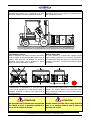
1
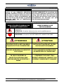
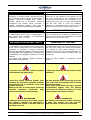
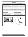
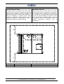
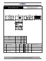
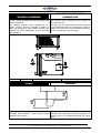
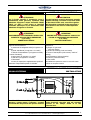
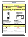
Condizionatori
d’aria
monoblocco
acqua-aria
ROOM-TOP
Packaged
air
conditioners
water to air
ROOM-TOP
MIRAC
WR/WH
MANUALE DI
INSTALLAZIONE E
MANUTENZIONE
INSTALLATION AND
MAINTENENCE
MANUAL
LEGGI E CONSERVA
QUESTE ISTRUZIONI
READ AND SAVE
THESE ISTRUCTIONS
VER.01/ 10
FROST ITALY s.r.l. -Via Trasimeno 46-int.1 – Z.I. – 36015 Schio – Vicenza – Italy
Tel. +39/+445/576772 – Fax +39/+445/576775 – e-mail [email protected]
1
COMPLIANCE
DECLARATION OF CONFORMITY
FROST ITALY s.r.l.
Via Lago di Trasimeno, 46
36015-Schio (VI)- Italy
For FROST ITALY
MIRAC UNIT:
MAKE
: FROST ITALY
SERIES : MIRAC WR-WH
MODEL : 6/100
Are complying at:
Machine Directive 98/37/CEE;
Directive PED 97/23/CE. Module D1;
Electromagnetic Compatibility Directive 89/336/CEE;
CONFORMITA’
DICHIARAZIONE DI CONFORMITA’
FROST ITALY s.r.l.
Via Lago di Trasimeno, 46
36015-Schio (VI)
Per la FROST ITALY :
L’unità MIRAC
MARCA
: FROST ITALY
SERIE
: MIRAC WR-WH
MODELLO : 6/100
Sono conformi a:
Direttiva Macchine 98/37/CEE;
Direttiva PED 97/23/CE. Modulo D1;
Direttiva Compatibilità Elettromagnetica 89/336/CEE;
2
FROST ITALY s.r.l. -Via Trasimeno 46-int.1 – Z.I. – 36015 Schio – Vicenza – Italy
Tel. +39/+445/576772 – Fax +39/+445/576775 – e-mail [email protected]
WARRANTY
GARANZIA
I climatizzatori della FROST ITALY
godono di una GARANZIA SPECIFICA,
secondo normativa europea, che decorre
dalla data di acquisto dell’apparecchio e
che l’utente è tenuto a documentare; nel
caso non sia in grado di farlo, la garanzia
decorrerà dalla data di fabbricazione
dell’apparecchio.
IN ALCUNE PARTI DEL MANUALE
SONO UTILIZZATI SIMBOLI DAL
SEGUENTE SIGNIFICATO:
The units produced by FROST ITALY have a
SPECIFIC WARRANTY (in accordance with
the european regulation) starting from the
selling date that has to be proved by the
user. In the case the user cannot show any
documentation the warranty will start
from the manufacturing date.
IN THIS MANUAL WILL BE USED
SOME SYMBOLS LIKE
THE FOLLOWING:
ATTENZIONE = per azioni che richiedono particolare cautela ed adeguata
preparazione
ATTENTION= for actions that can be done only by qualified persons.
VIETATO = per azioni che NON DEVONO essere assolutamente eseguite
FORBIDDEN = for actions that HAVE ABSOLUTELY NEVER TO BE DONE.
ATTENZIONE
ATTENTION
MONTARE FILTRI A RETE INGRESSO
ACQUA IN TUTTI GLI SCAMBIATORI.
INSTAL INLET WATER NET FILTERS
ON EACH HEAT EXCHANGER.
OBBLIGO MONTAGGIO FLUSSOSTATO
LATO ACQUA
THE FLOW SWITCH INSTALLATION
ON WATER SIDE IS COMPULSORY.
IN CASO DI ASSENZA LA
FROST ITALY DECLINA OGNI
RESPONSABILITA’ SU EVENTUALI
DANNI
OTHERWISE THE FROST ITALY
DOESN’T ASSUME ANY LIABILITY FOR
POSSIBLE CONSEQUENTLY DAMAGES
FROST ITALY s.r.l. -Via Trasimeno 46-int.1 – Z.I. – 36015 Schio – Vicenza – Italy
Tel. +39/+445/576772 – Fax +39/+445/576775 – e-mail [email protected]
3
AVVERTENZE GENERALI
Prima di procedere all'istallazione osservare scrupolosamente le seguenti avvertenze:
-
-
-
-
Leggere attentamente il presente libretto;
Movimentare l'unità con la massima cura (vedi sezione specifica) evitando di danneggiarla;
Eseguire tutti i lavori secondo le normative vigenti in materia nei diversi paesi;
Rispettare le distanze di sicurezza tra l'unità e altre strutture in modo da consentire un corretto
circolo d'aria. Garantire un sufficiente spazio d'accesso per le operazioni d'assistenza e
manutenzione.
Alimentazione dell'unità: i cavi elettrici devono essere di sezione adeguata alla potenza dell'unità ed i
valori della tensione d'alimentazione devono corrispondere con quelli indicati per le rispettive
macchine;
Tutte le macchine devono essere collegate a terra come da normativa vigente nei diversi paesi;
Collegamento idraulico da eseguire secondo le istruzioni al fine di garantire il corretto funzionamento
dell'unità;
Aggiungere del glicole etilenico nel circuito idraulico se durante il periodo invernale, l'unità non è in
funzione o non è svuotato l'impianto idraulico;
Validità garanzia: decade nel momento in cui non siano rispettate le indicazioni sopra menzionate e
se, all'atto della messa in funzione dell'unità, non sia presente il personale autorizzato dall'Azienda
(ove previsto nel contratto di fornitura) che dovrà redigere il verbale d'avviamento;
La documentazione fornita con l'unità deve essere consegnata al proprietario affinché la conservi con
cura per eventuali manutenzioni o assistenze.
GENERAL INSTRUCTIONS
Before proceed to the installation observe the following instructions scrupulously:
-
-
4
Read with attention the present book;
To move the unit with the greatest care (you view specific section) avoiding of damage it;
To execute all the works according to the provisions in force in the subject in the different countries;
To observe the safety distances between the unit and the other structures to consent a correct
airflow. To guarantee a sufficient space access for the assistance and servicing operations.
To feeding of the unit: the electric cables must be of conformed section to the power of the unit and
the values of the feeding voltage must coincide with those point out for the respective machinery;
All the machines must be connected to ground like from provisions in force in the different countries;
Hydraulic connection to perform according to the instructions at the purpose to guarantee the
correct operation of the unit;
To add ethylene glycol in the hydraulic circuit if during the winter period the unit is not in operation
or the hydraulic plant is not discharge;
Validity warranty: it declines at the moment in which the upstairs mentioned instructions are not
respected and if, when the unit is putted in function, where is no authorized staff of our firm (where
it is scheduled in the contract of supply) that it will compile the starting minutes.
The documentation furnished with the unit must be delivered to the owner so that he preserves it
with care for eventual servicing or assistances.
FROST ITALY s.r.l. -Via Trasimeno 46-int.1 – Z.I. – 36015 Schio – Vicenza – Italy
Tel. +39/+445/576772 – Fax +39/+445/576775 – e-mail [email protected]
ACCETTAZIONE DELL’UNITA'
ACCEPTANCE OF THE UNIT
Controllare, al momento della consegna dell'unità,
che corrisponda a quello indicato sul documento di
trasporto. Verificare l'integrità degli imballi e
dell'unità stessa. Se si dovessero riscontrare
incongruenze con l'ordine, danni, anomalie, o
fornitura incompleta, indicarlo sulla bolla di
consegna e avvertire tempestivamente l'azienda.
Check out, at the moment of the delivery of the
unit, that it coincides to that indicated on the
transport document. Check out the integrity of the
packing and of the unit. If it does not correspond
with the order must or there are damages,
anomalies, or incomplete supply, to point out it on
delivery note and to inform in good time the firm.
STOCCAGGIO DELL’UNITA'
STORE OF THE UNIT
Il condizionatore potrà essere immagazzinato in
locali protetti dalle intemperie con temperature
comprese tra i -20°C e i +55°C.
The air conditioner can be stored in protected room
from the bad weather with temperatures included
between the- 20°C and the +55°C.
MOVIMENTAZIONE DELL’UNITA'
HANDLING OF THE UNIT
Le unità FROST ITALY possono essere movimentate
sia con carrelli elevatori sia con gru. Eseguendo tale
operazione, si consiglia di prestare particolare
attenzione alla batteria alettata, cercando di evitare
sia danneggiata anche leggermente. Le operazioni di
movimentazione è consigliabile svolgerle con l'unità
imballata.
Come prima cosa verificare l'effettiva capacità di
sollevamento del macchinario.
The FROST ITALY units can be moved with lift truck
and with crane. Putting into practice this operation,
it is advised to lend special attention to the
aluminium finned coil trying to avoid damages. It is
advisable to make the moved operations with the
packed unit.
Come prima cosa verificare l'effettiva capacità
di sollevamento del macchinario.
As first step, check the real lift capacity of the
machinery.
L’unità deve essere sollevata facendo forza
solamente sul basamento dell’unità, evitando
assolutamente che si scarichino sforzi sulla
struttura superiore!
Utilizzare un tubo di acciaio legato ad elevata
resistenza
meccanica
inserendolo
negli
appositi fori predisposti nel basamento.
The unit must be raised forced only from the
base of the unit, for absolutely avoid to forced
the upper structure!
Insert steel beam inside the lower opening
corresponding support feet: The support
beam must be sufficient resistant for their
number and for the weight to raising.
ATTENZIONE
L’alettatura delle batterie di scambio termico
sono affilate e taglienti: non appoggiarsi e
porre attenzione quando si transita nelle loro
immediate vicinanze.
ATTENTION
The finning of the finned coil heat exchanger
is sharp and cutting: not lean and pay
attention when you travel in its proximity.
Verify the lifting capacity of machinery, before
starting.
FROST ITALY s.r.l. -Via Trasimeno 46-int.1 – Z.I. – 36015 Schio – Vicenza – Italy
Tel. +39/+445/576772 – Fax +39/+445/576775 – e-mail [email protected]
5
Sollevamento con carrello elevatore
Particolarmente adatto per lo spostamento su piani
orizzontali. Seguire lo schema riportato di seguito.
Raising with lift truck
Particularly proper for the shift on horizontal planes.
See the drawing below.
Sollevamento con gru
Usare un bilancino o un sistema di barre divaricatici.
Corde o cinghie di portata adeguata (evitare l'uso di
catene). Delle protezioni da mettere tra cinghia e
macchina, per evitare che la struttura si rovini.
Seguire lo schema riportato di seguito.
Raising with crane
To use a balance or a forked bars. Suitably sturdy
rope or straps (avoid the use of chains). Protections
to install among strap and machine, to avoid that the
structure ruins itself. To follow the scheme brought
as follows.
Il sollevamento va effettuato in 2 come da figura:
1,2. Le travi di sostegno Ø e le funi devono essere di
resistenza sufficiente in base al loro numero ed al
peso da sollevare.
The unit must be raised forced in 2 as show in the
picture. The support beams Ø and the cables must
have a sufficient resistance for their number and the
weight of the unit.
ATTENZIONE
ATTENTION
Nel momento del sollevamento controllare At the moment of the lift to check that the
che l'unità si trovi in perfetto equilibrio e unit is in perfect balance and it there is
non vi sia il rischio di caduta.
not the risk of fall.
6
FROST ITALY s.r.l. -Via Trasimeno 46-int.1 – Z.I. – 36015 Schio – Vicenza – Italy
Tel. +39/+445/576772 – Fax +39/+445/576775 – e-mail [email protected]
INSTALLAZIONE
INSTALLATION
Scelta del luogo d'istallazione
Prima di procedere al posizionamento dell'unità
FROST ITALY accertarsi che:
il luogo prescelto sia una superficie piana in grado si
sopportare il peso di funzionamento dell'unità (vedi
dati tecnici).
le distanze di sicurezza, tra l'unità e le altre
apparecchiature o strutture adiacenti, siano
rispettate. In tal modo l'aria sarà libera di circolare e
permetterà un corretto funzionamento da parte
dell'unità e sarà possibile prestare assistenza e
manutenzione, alla stessa, senza grosse difficoltà.
Choice of the place of installation
Before to proceed to the positioning of the FROST
ITALY unit to be sure that:
the select place is a plain; it must carry the weight
of operation of the unit (to look at technical data).
the safety distances, between the unit and the other
equipment or adjacent structures, must be
observed. In this way the air will be free to circulate
and will allow a correct operation from side of the
unit and it will be possible to lend assistance and
maintenance, to the same, without big problem.
Antivibranti in gomma
Al fine di evitare la trasmissione di vibrazioni è
opportuno istallare, negli appositi fori ricavati nei
piedini d'appoggio, dei supporti antivibranti,
seguendo lo schema indicato di seguito.
Rubber anti vibrating dampers
At the end to avoid the transmission of vibrations it
is opportune to install, in the provided holes in the
footsies of support, some anti-vibrating dumpers,
following the scheme brought as follows.
1
2
DP
DP=ANTIVIBRANTE/ANTI VIBRATING
FROST ITALY s.r.l. -Via Trasimeno 46-int.1 – Z.I. – 36015 Schio – Vicenza – Italy
Tel. +39/+445/576772 – Fax +39/+445/576775 – e-mail [email protected]
7
Posizionamento dell'unità
Posizionare l'unità e accertarsi che sia in bolla.
Verificare che sia consentito un accesso agevole alla
parte frigorifera, ventilante ed elettrica. Rispettare le
distanze di sicurezza tra l'unità e altre strutture, in
modo da consentire un corretto circolo d'aria.
Garantire un sufficiente spazio d'accesso per le
operazioni d'assistenza e manutenzione. Vedere i
disegni dimensionali e d'ingombro seguenti.
A
C
8
Positioning of the unit
Install the unit and be sure that it is in plain
surface. Verify that I have allowed a good access to
the refrigerant circuit, ventilation box and electric
side. To observe the safety distances between the
unit and the other structures to consent a correct
airflow. To guarantee a sufficient space access for
the assistance and servicing operations. See the
following
dimensional
drawings
and
of
encumbrance.
2000 mm MIN
2000 mm MIN
FROST ITALY s.r.l. -Via Trasimeno 46-int.1 – Z.I. – 36015 Schio – Vicenza – Italy
Tel. +39/+445/576772 – Fax +39/+445/576775 – e-mail [email protected]
DIMENTIONAL DRAWING
MIRAC WR-WH 6/100
DISEGNO DIMENSIONALE
MIRAC WR-WH 6/100
MODELLO
A
[mm]
B
[mm]
C
[mm]
6-10
1400
1000
750
12-40
1750
1400
855
50-65
2250
1750
1000
80-100
2600
2000
1500
INGRESSO
CAVI
ELETTRICI
SCARICO
CONDENSA
1)
FINNED
COIL
1)
BATTERIA ALETTATA
6)
2)
CASSETTA ELETTRICA
7)
3)
VENTILATORE
8)
4)
USCITA ACQUA
4)
OUTLET
WATER
5)
INGRESSO ACQUA
5)
INLET
WATER
FILTRO ARIA
6)
CONTROL
7)
PANEL
INDOOR
3)
8)
FAN
2)
INLET ELECTRICAL LINE
DISCHARGE CONDENSATE
AIR FILTER
FROST ITALY s.r.l. -Via Trasimeno 46-int.1 – Z.I. – 36015 Schio – Vicenza – Italy
Tel. +39/+445/576772 – Fax +39/+445/576775 – e-mail [email protected]
9
COLLEGAMENTO
SCARICO CONDENSA
CONDENSE DISCHARGE
CONNECTION
L’unità è dotata di scarico dell’acqua prodotta nelle
batterie evaporanti.
Tali tubazioni possono essere collegate ad uno
scarico d’acqua presente nell’edificio dotato di
sifone, per garantire lo scarico della condensa dalla
bacinella ed evitare l’aspirazione di aria inquinata
dalla fognatura.
The unit has a water discharge for the condense of
the evaporator coil.
The pipes can be connect with the water discharge
of the building that must be provide with a siphon to
ensure the correct flow of the condensate and avoid
suction of polluted air from sewerage.
SC
1”
SCARICO CONDENSA
SIPHONS
40
40
SIFONI
CONDENSE DISCHARGE
Per evitare odori sgradevoli e consentire il corretto
drenaggio della condensa, I sifoni devono essere
realizzati come in figura.
10
To avoid the aspiration of bad smells and to
guarantee the correct draining of the condense, the
siphons have to be realized according the figure
above.
FROST ITALY s.r.l. -Via Trasimeno 46-int.1 – Z.I. – 36015 Schio – Vicenza – Italy
Tel. +39/+445/576772 – Fax +39/+445/576775 – e-mail [email protected]
COLLEGAMENTI IDRICI
ATTENZIONE
Per il circuito idraulico è necessario, pena il
decadimento della garanzia, installare sulla
tubazione d'ingresso acqua dell'unità FROST
ITALY, un filtro a rete contro le impurità
contenute nell'acqua ed un flussostato sulla
tubazione di ingresso o di uscita.
ATTENZIONE
ASSICURARSI CHE L’IMPIANTO IDRICO SIA
RIEMPITO D’ACQUA ED IN PRESSIONE
(1,5-2 bar),
SENZA BOLLE D’ARIA
Sul circuito idrico si consiglia l'installazione della
seguente strumentazione:
- 2 manometri di adeguata scala (in ingresso e in
uscita)
- 2 giunti antivibranti (in ingresso e in uscita)
- 3 valvole d'intercettazione (in ingresso normale,
in uscita di taratura)
- 2 termometri (in ingresso e in uscita)
- 2 sfiati aria (in ingresso e in uscita)
- 1 flussostato.
- un vaso di espansione supplementare qualora il
contenuto d’acqua dell’impianto lo richieda.
INSTALLAZIONE FLUSSOSTATO
ACQUA ESTERNO
Installare il flussostato FL, sulla tubazione di
ingresso o uscita acqua e collegare i contatti
ai morsetti X3-X4 presenti nel quadro elettrico
HYDRAULIC CONNECTIONS
ATTENTION
For the hydraulic circuit is necessary, penalty
decline warranty, to install on the inlet water
of the FROST ITALY unit, a net filter against
the impurities contained in the water and a
flow switch on the inlet or outlet hydraulic
pipe-line.
ATTENTION
INSURE THAT THE HYDRAULIC CIRCUIT IS
FILLED OF WATER AND ON PRESSURE
(1,5-2 bar),
WITHOUT AIR BOILS
On the water circuit to install the following
equipment:
-2 gauges of right scale
(inlet and outlet)
-2 joints anti vibrating (inlet and outlet)
-3 valves of interception (inlet normal, outlet of
setting)
-2 thermometers (inlet and outlet)
-2 leaks air (inlet and outlet)
-1 flow switch
-An additional expansion vessel in case the water
volume in the plant involve.
EXTERNAL WATER FLOW SWITCH
INSTALLATION
Install the water flow switch on the inlet or
outlet hydraulic pipe-line and the contacts
connect in the clamps X3-X4 in to the
electrical box.
FROST ITALY s.r.l. -Via Trasimeno 46-int.1 – Z.I. – 36015 Schio – Vicenza – Italy
Tel. +39/+445/576772 – Fax +39/+445/576775 – e-mail [email protected]
11
ELECTRICAL CONNECTIONS
COLLEGAMENTI ELETTRICI
ATTENTION
ATTENZIONE
The unit must be switch on when the
installation works are completed (air ducts
and electric). All the operations must be
achieved by qualified personal.
All the electric connections must be
performed according to the previsions force in
subject in the different countries;
To observe the indications of connection of
the conductors phase, neutral and ground;
The line of feeding will have a provided
protection against the short-circuits section
the plant awry I respect the other uses;
The voltage will be included within a
tolerance of the ± 10% of the nominal
voltage of feeding of the unit.
If these parameters have not observed, to
contact the body that supply the energy.
L'unità va alimentata solamente a lavori
d'installazione ultimati (canalizzazioni aria ed
elettrici). Tutte le operazioni devono essere
eseguite da personale qualificato.
Tutti i collegamenti elettrici devono essere
eseguiti come previsto dalle normative vigenti
in materia nei diversi paesi;
Rispettare le indicazioni di collegamento dei
conduttori fase, neutro e terra;
La linea d’alimentazione dovrà avere a monte
un'apposita protezione contro i cortocircuiti
che sezioni l'impianto rispetto le altre utenze.
La tensione dovrà essere compresa entro una
tolleranza del ± 10% della tensione nominale
d’alimentazione della macchina.
Qualora questi parametri non fossero
rispettati,
contattare
l'ente
erogatore
dell'energia.
Accesso al quadro elettrico
ed ai componenti elettronici
Il quadro elettrico è situato all'interno del vano
compressore e vi si accede rimovendo il pannello
frontale dell'unità, svitando le viti di fissaggio. Per
accedere ai componenti elettrici e alla morsettiera,
togliere tensione e sbloccare il pannello con
l’apposita chiave.
Collegamento elettrico di potenza
Per il collegamento elettrico, alla rete di
alimentazione, portare il cavo di alimentazione al
quadro elettrico all'interno dell'unità. Collegarsi
all'interruttore rispettando le 3 fasi (L1,L2,L3), il
neutro (N), terra (PE) nel caso di alimentazione
trifase con neutro (400V-50Hz-3+N+PE).
Collegamenti elettrici opzionali
1. On-Off remoto (morsetti 10-11)
2. Estate-Inverno remoto (morsetti 68-69)
(solo per le unità in pompa di calore)
3. Contatto allarme (morsetti 30-31)
Access to the electrical box
and to the electronic components
The electrical board is situated to the inside of the
compressor vain and we enter moving the frontal
panel of the unit, unscrewing the screws fixing. To
access the electric components and to the terminal
board, switch off voltage and decontrol the panel
with the key.
Connection of electrical power
For the electric connection, to the net of feeding, to
bring the cable of feeding to the electrical board to
the inside of the unit. To connect to the switch the 3
phases (L1, L2, L3), the neuter (N), ground (PE) in
the case of feeding three phase with neuter
(400V-50Hz-3+N+PE).
Wirings optional connections
1. Remote On-Off (clamps 10-11)
2. Remote Summer-Winter (clamps 68-69)
(only for heat pump units)
3. Contact alarm (clamps 30-31)
Tutte le unità FROST ITALY sono predisposte per il
controllo e il monitoraggio remoto della macchina.
Per ricavarsi il numero dei morsetti, per il
collegamento remoto, fare riferimento allo schema
elettrico fornito assieme all'unità.
All the FROST ITALY units have gotten ready for the
control and the remote monitoring of the machine.
For extract the number of the clamps, for the
remote connection, make reference to the wiring
furnished diagram together to the unit.
Morsetti / Clamps
10-11
68-69
30-31
12
Funzione/Function
Modo/Mode
Tipo/Type
ON/OFF REMOTO
APERTO/CHIUSO
CONTATTO PULITO
REMOTE ON/OFF
OPEN/CLOSE
CLEAN CFONTACT
ESTATE/INVERNO REMOTO
SUMMER/WINTER REMOTE
CONTATTO ALLARME
ALARM CONTACT
APERTO/CHIUSO
CONTATTO PULITO
OPEN/CLOSE
CLEAN CFONTACT
USCITA A RELE’
RELAY OUTPUT
CA 230V
AC 230V
FROST ITALY s.r.l. -Via Trasimeno 46-int.1 – Z.I. – 36015 Schio – Vicenza – Italy
Tel. +39/+445/576772 – Fax +39/+445/576775 – e-mail [email protected]
COLLEGAMENTO
CANALIZZAZIONI ARIA
AIR DUCTS
CONNECTION
Eseguire il collegamento dei canali aria alla bocca di
mandata e di ripresa, ancorandosi sul bordo interno
o esterno dei profili in alluminio.
Verificare le perdite di carico calcolate nelle
canalizzazioni con la prevalenza statica utile del
ventilatore:
Achieve the air ducts connection to discharge and
renewal air section of the unit, anchorage to the
internal or external boundary of aluminium profiles.
Verify the air pressure drop in the ducts and the
head static pressure of the fan:
PRESSIONE STATICA VENTILATORE (Pa) ≥
PERDITA DI CARICO CANALIZZAZIONI (Pa)
HEAD STATIC FAN PRESSURE (Pa) ≥
AIR DUCTS PRESSURE DROP (Pa)
CONTROLLO DELL'UNITA'
ATTENZIONE
TO CHECK OF THE UNIT
ATTENTION
Prima di avviare l'unità, eseguire il controllo
indicato in questo paragrafo.
Before start the unit, perform the check
pointed out in this paragraph.
Controllo circuito elettrico
Check electrical circuit
- La tensione di alimentazione dovrà essere
compresa entro una tolleranza del ± 10% della
tensione nominale di alimentazione dell'unità,
indicata sul pannello del quadro elettrico.
230V / 400V ± 10%
- Verificare
le
connessioni
dei
conduttori
d'alimentazione ed il loro stato.
- Verificare il collegamento a terra.
- Verificare il collegamento remoto (se installato) o
la presenza dei ponti sui morsetti.
- The voltage of supply will be included inside a
tolerance of the ± 10% of the nominal tension of
power supply of the unit, indicated on the panel of
the electrical board.
230V / 400V ±10%
- To verify the connections of the conductors of
power supply and their state.
- To verify it connected to ground.
- To verify the remote connection (if installed) or
the presence of the bridges on the clamps.
ATTENZIONE
Controllare il serraggio dei morsetti presenti
nel quadro elettrico e ripetere l’operazione
dopo una settimana dalla messa in funzione.
ATTENTION
Check the clamping state of the connection
clamps of the electrical board after a week
from the starting of the unit.
FROST ITALY s.r.l. -Via Trasimeno 46-int.1 – Z.I. – 36015 Schio – Vicenza – Italy
Tel. +39/+445/576772 – Fax +39/+445/576775 – e-mail [email protected]
13
Le unità con alimentazione trifase sono dotate
del dispositivo di controllo sequenza fasi. In tal
modo si evitano errori di alimentazione elettrica.
The units with three phase supply are
completed with phases sequence controller
device. So it’s impossible make mistake in the
power supply operation.
ATTENZIONE
L’UNITA’ E’ PREDISPOSTA CON IL CONTROLLO
SEQUENZA FASI CF1. SE IL COLLEGAMENTO
DELLE FASI DI ALIMENTAZIONE NON E’
CORRETTO
IL
DISPLAY
DEL
MICROPROCESSORE NON SI ACCENDE.
ATTENTION
THE
UNIT
HAS
PHASE
SEQUENCE
CONTROLLER CF1. IF THE ELECTRICAL
SUPPLY OF PHASES IS NOT CORRECT, THE
MICROPROCESSOR’S DISPLAY DON’T TURN
ON.
L1 L2
L1
L2
L3
L3
R
L1 L2 L3
11
12
12 14
14
11
Caratteristiche generali
General features
-Controllo sequenza fasi.
-Controllo mancanza fase totale o parziale.
-Autoalimentato.
-Uscita a relè con contatto di scambio.
-LED verde di segnalazione alimentazione
intervento.
-Ripristino automatico.
-Phase sequence control.
-Total or partial phase loss control.
-Powered by monitored voltage.
-Relay output with changeover contact.
-Green LED power ON and FAULT tripping indication.
-Automatic resetting.
ed
Funzionamento
Operating
Quando le fasi sono tutte presenti e la
sequenza è corretta, il LED VERDE R è acceso
fisso ed il relè di uscita è eccitato.
With all phases detected and correct phase
sequence, the GREEN LED R is costantly
switched on and the output relay is energised.
ATTENZIONE
Se il LED VERDE R lampeggia:
-sequenza fasi di alimentazione errata.
ATTENTION
If the GREEN LED R flashes:
-incorrect power supply phase sequence.
Oppure:
-mancanza di una fase.
Oppure:
-abbassamento di una tensione di alimentazione,
sotto il 70% rispetto alle altre tensioni concatenate.
Or:
-phase loss.
Or:
-one of the phase-to-phase voltages falls below
70%of the other phase-to-phase voltage value.
14
FROST ITALY s.r.l. -Via Trasimeno 46-int.1 – Z.I. – 36015 Schio – Vicenza – Italy
Tel. +39/+445/576772 – Fax +39/+445/576775 – e-mail [email protected]
AVVIAMENTO DELL'UNITA'
STARTING OF THE UNIT
ATTENZIONE
Il primo avviamento deve essere eseguito con
le impostazioni standard, solo a collaudo
ultimato variare i valori.
ATTENTION
The first starting of the unit must be done
with the standard configure, only after
change the configuration values.
Avviamento dell'unità
Alimentare l'unità agendo sul blocco-porta e
sollevando la leva degli interruttori automatici;
Lasciare alimentata l’unità per almeno 6 ore;
Si consiglia al primo avviamento di collegare il
terminale REMOTO a bordo macchina per
controllare il corretto funzionamento dell’unità.
Accendere l'unità selezionare dal menù
principale ON/OFF UNITA’ e premere ENTER,
con accensione del relativo led;
Attendere la temporizzazioni dei compressori;
Verificare la corrente d'assorbimento del
compressore e confrontarla con i dati di targa.
Starting of the unit
- Open the electrical board and turn on the
automatic switch for supply the unit
- Supply the unit for 6 hour
- We advise at the first starting, connect the
REMOTE terminal near the unit for control the
mode of operation of the unit, after connect the
terminal in the room. Turn on the unit by
selection ON/OFF UNIT in the main menù and
push the ENTER button in the remote display
- Wait the compressor timing (Led compressor 1
has intermittent light).
- To verify the current of absorption of the
compressor and to compare it with the data of
rating plate.
Controllo del compressore e dei ventilatori
Verificare il livello di rumorosità del compressore non
sia superiore al normale e che la pressione di
mandata sia superiore alla pressione di aspirazione,
in caso contrario controllare la sequenza delle fasi di
alimentazione L1-L2-L3 (senso di rotazione non
corretto).
Assicurarsi che il valore di tensione rientri nei limiti
prefissati e che lo sbilanciamento tra le tre fasi
(tensione trifase) non sia superiore al ± 3%.
Per i ventilatori centrifughi VERIFICARE LA
TENSIONE DELLE CINGHIE DI TRASMISSIONE
Check of the compressors and fans
To verify that the noisiness level of the compressor
it is not superior to the normal and that the delivery
head it is superior to the pressure of suction, in
opposite case to check the sequence of the phases
of supply L1-L2-L3 (sense of rotation not correct).
Making sure that the value of voltage re-enters in
the fixed limits and that the unbalance between the
three phases (three-phase voltage) it is not superior
to ± 3%.
About centrifugal fans, VERIFY THE TENSION OF
TRASMISSION BELTS
ATTENZIONE
Verificare le correnti d'assorbimento del
compressore e dei ventilatori confrontarle con
i dati di targa.
ATTENTION
To verify the current of absorption of the
compressor and to compare it with the data of
rating plate.
Soste prolungate
Per lunghi periodi di fermata sezionare la macchina
agendo sull'interruttore generale del quadro
elettrico.
Alla ri-accensione, lasciare l’unità alimentata, con
tutti gli interruttori automatici chiusi, per almeno 6
ore, prima di riavviarla.
Prolonged breaks
For long periods of stop, to sections the machine
operating on the general switch of the electrical
board.
When restart the unit, wait 6 hour with the unit
supplied with all automatic switches OFF before
starting the unit.
FROST ITALY s.r.l. -Via Trasimeno 46-int.1 – Z.I. – 36015 Schio – Vicenza – Italy
Tel. +39/+445/576772 – Fax +39/+445/576775 – e-mail [email protected]
15
VENTILATORI
-
-
-
Verificare il fissaggio dei ventilatori e dei loro supporti, in modo tale da eliminare eventuali
vibrazioni indotte nella struttura.
Per
i
ventilatori
centrifughi: verificare periodicamente la tensione delle cinghie.
Spegnere l’unità e togliere tensione:
applicare una forza P, tramite dinamometro, a
metà cinghia in modo da provocare la freccia F1:
F1=(L1/100)x1,5 [mm]
To verify the fixing of the fans and of their
supports for eliminate possible vibrations induced
in the structure.
For centrifugal fans, verify the right stress of belts.
Switch off the unit and disconnect the
power supply: apply the force P at middle of the
belt through dynamometer, able to give an arrow
F1:
F1=(L1/100)x1,5 [mm]
Se P<35N occorre tendere la cinghia
If P<35N needs tighten the belt again
Se P>50N occorre allentare la cinghia
If P>50N the belt is too much tight
ATTENZIONE
VERIFICARE CHE LA CORRENTE
ASSORBITA DAI VENTILATORI SIA
MINORE DI QUELLA DI TARGA.
16
FANS
ATTENTION
PLEASE VERIFY THAT THE CURRENT
ADSORBED FROM THE FANS IS LOWER
THAN THE NOMINAL.
FROST ITALY s.r.l. -Via Trasimeno 46-int.1 – Z.I. – 36015 Schio – Vicenza – Italy
Tel. +39/+445/576772 – Fax +39/+445/576775 – e-mail [email protected]
MAINTENANCE
MANUTENZIONE
ATTENTION
ATTENZIONE
Prima di procedere a qualsiasi operazione di
manutenzione dell'unità, togliere la tensione
d'alimentazione. Una pulizia costante delle
batterie assicurerà un funzionamento corretto
dell'unità. È consigliabile un controllo
stagionale di tutte le funzioni dell'unità ed
almeno un controllo annuale che deve essere
eseguito dai centri assistenza autorizzati
Before to proceed to any operation of
maintenance of the unit, switch off the
voltage of supply. A constant cleaning of the
coils will make sure a correct operation of the
unit. It is advisable a seasonal check of all the
functions of the unit and at least an annual
control that must be performed by the centers
authorized assistance.
Pulizia della batteria
Cleaning of the coil
- Procedere con una spazzola e un getto d'aria alla
pulizia della superficie della batteria per togliere
eventuali impurità.
- Verificare che le alette d'alluminio della batteria
non siano piegate o in posizione tale da non
consentire un normale passaggio del flusso d'aria.
- Rimuovere eventuali pieghe con l'apposito
pettine.
- To proceed with a brush and a blast for the
cleaning of the surface of the coil to remove possible
impurity.
- To verify that the aluminum fins of the coil are
not folded up or in such position to not allow a
normal airflow.
- To remove possible folds with the appropriate
comb.
Circuito elettrico
Electric circuit
- Verificare lo stato dei cavi d'alimentazione
dell'unità.
- Controllare lo stato di serraggio dei morsetti di
connessione dei cavi elettrici di potenza e di
segnale. (Cura del centro assistenza autorizzato).
- Verificare che i valori di tensione rientrino nei
valori descritti al punto "Controllo del circuito
- To verify the state of the cables of supply of the
unit.
- To check the clamping state of the connection
clamps of the electric power cables and of signal.
(Supervised by the authorized assistance centre).
- To verify that the values of voltage re-enter in
the described values to the point "Control electrical
circuit."
elettrico".
Circuito idraulico
Hydraulic circuit
- Ad ogni avviamento dopo un periodo di sosta
dell'unità, verificare il corretto funzionamento della
pompa e, in caso di blocco della girante, smontare la
pompa dalla macchina, togliere la calotta della
girante e rimuovere eventuali incrostazioni presenti
sulla girante.
- Verificare che non ci siano perdite sul circuito
idraulico.
- Controllare la portata d'acqua misurando il DT
tra l'ingresso e l'uscita dello scambiatore.
- Procedere alla pulizia del filtro acqua installato
sulla linea idrica.
In each starting, after a pause period of the unit,
to verify the correct operation of the pomp and, in
case of block of the impeller, to get off the pomp
from the machine, to remove the cap of the impeller
and to remove possible scales present scales on the
impeller.
- To verify that there are not leaks on the
hydraulic circuit. .
- To check the flow of water measuring the DT
between the inlet and the outlet of the exchanger.
- To proceed to the cleaning of the water filter
installed on the water line.
-
FROST ITALY s.r.l. -Via Trasimeno 46-int.1 – Z.I. – 36015 Schio – Vicenza – Italy
Tel. +39/+445/576772 – Fax +39/+445/576775 – e-mail [email protected]
17
Verifica funzioni e allarme
(solo personale autorizzato)
Functions and alarm check
(only authorized personal)
- Controllare che la lettura delle sonde di
temperatura corrisponda a quella reale misurata con
un termometro e procedere se necessario alla
taratura.
- Verificare, durante il funzionamento dell'unità, le
pressioni di mandata e aspirazione. È necessario
collegarsi con dei manometri sulle opportune prese
di servizio predisposte nei circuiti frigoriferi.
- To check that the reading of the temperature
probes corresponds to the real one measured with a
thermometer and to proceed, if necessary, to the
setting.
- To verify, during the operation of the unit, the
delivery and suction pressures. It is necessary to
connect with the manometers on the opportune
taking of service predisposed in the refrigerant
circuits.
Ventilatori
Fans
Verificare il fissaggio dei ventilatori e dei loro
supporti, in modo tale da eliminare eventuali
vibrazioni indotte nella struttura.
VERIFICARE LO STATO DI TENSIONE ED
USURA DELLE CINGHIE DI TRASMISSIONE
PERIODICAMENTE.
Al primo avviamento, verificare le cinghie
dopo
circa
4
ore
di
funzionamento
continuativo
To verify the fixing of the fans and of theirs supports
for eliminate possible vibrations induced in the
structure.
VERIFY THE TENSION AND THE USURY OF
THE TRASMISSION BELT PERIODICALY.
SMANTELLAMENTO DELL'UNITA'
DEMOLITION OF THE UNIT
La macchina è stata progettata e costruita per
garantire un funzionamento continuo. La durata di
alcuni componenti principali, quali il ventilatore ed il
compressore, dipende dalla manutenzione cui sono
stati sottoposti.
In caso di smantellamento dell'unità, l'operazione
dovrà essere eseguita da personale frigorista
specializzato.
Il fluido frigorigeno e l'olio lubrificante contenuti nel
circuito dovranno essere recuperati, in accordo con
le norme vigenti nel Vostro Paese.
The machine has been designed and manufactured
to guarantee a continuity operation. The life of some
main components, such as the fan and compressor,
depends on the maintenance to which they are
subjected.
If is necessary the demolition of the unit, it must be
performed by the specialized refrigerating
technicians.
The refrigerating fluid and lubrication oil contained
in the circuit must be recovered, in compliance with
the regulations in force in your country.
18
At the first start, verify the belt after 4 hours
of continuous work.
FROST ITALY s.r.l. -Via Trasimeno 46-int.1 – Z.I. – 36015 Schio – Vicenza – Italy
Tel. +39/+445/576772 – Fax +39/+445/576775 – e-mail [email protected]
TECHNICAL FEATURES
MIRAC WR/WH 6-30
CARATTERISTICHE TECNICHE
MIRAC WR/WH 6-30
MIRAC
Potenza frigorifera(1)
Cooling capacity
Unità
Unit
6
8
10m
10
12
16
20
30
kW
6,3
7,5
8,6
8,3
10,3
16,0
20,1
28,3
kW
5,4
6,3
7,3
7,0
8,8
13,6
17,1
24,1
kW
7,8
9,2
10,6
10,2
12,1
18,8
23,3
33,3
(1)
Potenza frigorifera sensibile
Sensible cooling capacity
Potenza in
riscaldamento(2)
Heating capacity
Refrigerante
Tipo
Refrigerant
Type
Compressori
n°/Tipo
Compressors
n°/Type
R407C
1
1
1
1
1
2
2
2
kW
1,8
2
2,4
2,3
2,5
3,9
4,7
6,7
A
8
9
11
4
5
7
8
12
kW
2,3
2,7
3,2
3,1
3,3
5,0
6,1
8,7
A
11
12
14
5
6
9
11
16
A
41
47
56
21
23
35
42
60
n°
1
1
1
1
1
2
2
2
n°
1
1
1
1
1
2
2
2
n°
1
1
1
1
1
1
1
1
m3/h
1.200
1.400
1.600
1.600
2.000
3.000
3.800
5.300
(1)
Potenza assorbita nominale
Nominal absorbed power
(1)
Corrente assorbita nominale
Nominal absorbed current
(3)
Massima potenza assorbita
Maximum absorbed power
Corrente massima assorbita(3)
Full load current
Corrente massima allo spunto
Maximun starting current
Circuiti frigoriferi
Refrigerant circuits
Gradini di parzializzazione
Capacity steps
N° ventilatori
N° fans
Portata d’aria totale
Total air flow
Scambiatore la aria interna
Tipo
Batteria alettata
Indoor air heating exchanger
Type
Finned coil
Potenza installata
Motor input
Pressione statica utile
Useful static pressure
Portata nominale acqua(1)
Nominal water flow
Perdite di carico lato acqua(1)
Water side pressure drops
Scambiatore acqua
Water heat exchanger
Livello di pressione sonora(4)
Sound level pressure
Alimentazione elettrica
Power supply
kW
0,190
0,221
0,253
0,253
0,316
0,474
0,600
0,837
Pa
150
150
150
150
150
150
150
150
m3/h
1,4
1,6
1,8
1,8
2,1
3,3
4,1
5,8
kPa
7,6
7,1
7,4
6,9
7,9
11,3
11,8
12,7
56
58
59
Tipo
Piastre saldo-brasate
Type
Brazed welded-plates
dB(A)
51
53
53
230V/1+N+PE/50Hz
53
55
400V/3+N+PE/50Hz
FROST ITALY s.r.l. -Via Trasimeno 46-int.1 – Z.I. – 36015 Schio – Vicenza – Italy
Tel. +39/+445/576772 – Fax +39/+445/576775 – e-mail [email protected]
19
TECHNICAL FEATURES
MIRAC WR/WH 35-100
CARATTERISTICHE TECNICHE
MIRAC WR/WH 35-100
MIRAC
Potenza frigorifera(1)
Cooling capacity
Unità
Unit
35
40
50
55
65
80
100
kW
32,8
40,7
49,8
56,6
65,6
81,4
99,6
kW
27,9
34,6
42,3
48,1
55,8
69,2
84,7
kW
38,5
47,8
58,5
66,6
77,0
95,6
116,9
(1)
Potenza frigorifera sensibile
Sensible cooling capacity
(2)
Potenza in riscaldamento
Heating capacity
Refrigerante
Tipo
Refrigerant
Type
Compressori
n°/Tipo
Compressors
n°/Type
R407C
2
2
2
2
2
2
2
kW
7,7
9,7
11,8
13,5
15,5
19,3
23,6
A
14
17
21
24
28
34
42
kW
10,1
12,5
15,4
17,5
20,1
25,1
30,7
A
18
22
27
31
36
45
55
A
69
86
106
120
138
172
211
n°
2
1
1
1
1
1
1
n°
2
2
2
2
2
2
2
n°
1
1
1
1
1
1
1
m3/h
1.200
1.400
1.600
1.600
2.000
3.000
3.800
(1)
Potenza assorbita nominale
Nominal absorbed power
(1)
Corrente assorbita nominale
Nominal absorbed current
(3)
Massima potenza assorbita
Maximum absorbed power
Corrente massima assorbita(3)
Full load current
Corrente massima allo spunto
Maximun starting current
Circuiti frigoriferi
Refrigerant circuits
Gradini di parzializzazione
Capacity steps
N° ventilatori
N° fans
Portata d’aria totale
Total air flow
Scambiatore la aria interna
Tipo
Batteria alettata
Indoor air heating exchanger
Type
Finned coil
Potenza installata
Motor input
Pressione statica utile
Useful static pressure
Portata nominale acqua(1)
Nominal water flow
Perdite di carico lato acqua(1)
Water side pressure drops
Scambiatore acqua
Water heat exchanger
Livello di pressione sonora(4)
Sound level pressure
Alimentazione elettrica
Power supply
20
kW
0,963
1,200
1,469
1,658
1,927
2,385
2,922
Pa
150
150
150
150
150
150
150
m3/h
6,8
8,4
10,3
11,7
13,5
16,8
20,5
kPa
8,4
8,5
44,7
45,1
44,0
43,7
45,8
70
72
Tipo
Piastre saldo-brasate
Type
Brazed welded-plates
dB(A)
61
63
64
66
68
400V/3+N+PE/50Hz
FROST ITALY s.r.l. -Via Trasimeno 46-int.1 – Z.I. – 36015 Schio – Vicenza – Italy
Tel. +39/+445/576772 – Fax +39/+445/576775 – e-mail [email protected]
REFERENCES CONDITIONS
CONDIZIONI DI RIFERIMENTO
(1) Nominal conditions:
Water temperature T=30/35°C
Indoor temperature T=27°C,DB–19,5°C,WB
(2) Nominal conditions:
ONLY HEAT PUMP VERSION
Water temperature T=15/10°C
Indoor temperature T=20°C
(3) Max admissible conditions.
(4) Full sound pressure level measured at 5m
from the unit in free field (ISO3744)
(1) Condizioni nominali:
Temperatura acqua T=30/35°C
Temperatura aria interna T=27°C,BS–19.5°C,BU
(2) Condizioni nominali:
SOLO VERSIONI POMPA DI CALORE
Temperatura acqua T=15/10°C
Temperatura aria interna T=20°C
(3) Alle condizioni limite di funzionamento.
(4) Livello di pressione sonora rilevata in campo
libero a 5m dall’unità (ISO3744)
LIMITI DI
FUNZIONAMENTO
Temperatura aria
ingresso batteria BS
Temperatura aria
ingresso batteria BU
Temperatura acqua
uscita scambiatore
OPERATION
LIMITS
RAFFRESCAMENTO RISCALDAMENTO
COOLING
HEATING
Min
Max
Min
Max
°C
19
45
11
35
°C
°C
12
32
-
-
°C
°C
22
52
4
18
°C
Temperature DB
air inlet coil
Temperature WB
air inlet coil
Temperature water
outlet exchanger
PERCENTUALE
GLICOLE ETILENICO
IN PESO (%)
10
20
30
40
50
Temperatura dicongelamento
-3.6
-8.7
-15.3
-23.5
-35.5
Freezing point
Coeff.corr. resa frigorifera
0.986
0.980
0.973
0.966
0.960
Cooling capacity corr. factor
Coeff.corr. potenza assorbita
1.000
0.995
0.990
0.985
0.975
Absorbed power corr. factor
Coeff.corr. portata miscela
1.023
1.054
1.092
1.140
1.200
Mixture flow corr. factor
Coeff.corr. perdita di carico
1.061
1.114
1.190
1.244
1.310
Pressure drop corr. factor
FOULING FACTOR CORRECTION
FATTORI DI INCROSTAZIONE
Le prestazioni delle unità indicate nelle tabelle sono
fornite per condizione di scambiatore pulito (fattore
d'incrostazione=0). Per valori differenti del fattore
d'incrostazione, le prestazioni fornite dovranno
essere corrette con i fattori indicati.
FATTORI D’INCROSTAZIONE
EVAPORATORE (m2 °C/W)
ETHYLENE GLYCOL
PERCENT BY
WEIGHT (%)
Unit performances reported in the table are given for
the condition of clean exchanger (fouling factor=0).
For different fouling factors values, unit performances
should be corrected with the correction factors shown
above.
F1
F2
0 (Evaporatore pulito)
1
-4
0.44 x 10
0,98
0.88 x 10⁻⁴
0,96
1.76 x 10⁻⁴
0,93
F1 = fattore di correzione potenza resa
F2 = fattore di correzione potenza assorbita
1
0,99
0,99
0,98
EVAPORATOR FOULING
FACTORS (m2 °C/W)
0 (Clean evaporator)
0.44 x 10⁻⁴
0.88 x 10⁻⁴
1.76 x 10⁻⁴
F1 = capacity correction factors
F2 = compressor power input correction factors
FROST ITALY s.r.l. -Via Trasimeno 46-int.1 – Z.I. – 36015 Schio – Vicenza – Italy
Tel. +39/+445/576772 – Fax +39/+445/576775 – e-mail [email protected]
21
BINDING CONTROLS
AND CHECKS
CONTROLLI E VERIFICHE
OBBLIGATORIE
ATTENZIONE
ATTENTION
Le verifiche riportate di seguito sono
obbligatorie; la loro non esecuzione
comporta il decadimento della garanzia
ed esonera la FROST ITALY srl da ogni
responsabilità conseguenti a danni
provocati.
Checks write here below are binding;
The not execution of them decline FROST
ITALY srl from any responsibility for
damages and cause
the DECLINE OF THE WARRANTY.
CONTROLLI E VERIFICHE
UNITA’ ROOM-TOP
CHECKS AND CONTROLS
ROOM TOP-UNIT
CONTROLLI AL PRIMO AVVIAMENTO
1. Verifica visiva dello stato dell’unità
(presenza di ammaccature, ecc.).
2. Verifica della tensione di alimentazione
dell’unità: i limiti sulla tensione di
alimentazione sono del ± 10%; valori della
tensione
inferiori
possono
provocare
surriscaldamenti al motore elettrico del
compressore, in tal caso contattare l’ente
erogatore dell’energia.
3. Verifica del serraggio dei morsetti cavi sul
quadro elettrico, in particolare sui teleruttori
ed interruttori automatici dei compressori e
ventilatori.
4. Verifica della libera rotazione del ventilatore
centrifugo e dell’assenza di corpi estranei
all’interno delle griglie e del vano aria.
5. Verifica
del
corretto
cablaggio
dell’alimentazione elettrica, se trifase,
rispettando la corretta posizione del neutro
e delle fasi.
6. Verifica della presenza del filtro ingresso aria
batteria interna
7. Verifica della tensione di serraggio della
cinghia del ventilatore centrifugo.
22
CHECKS FOR THE FIRST START
1)
2)
3)
4)
5)
6)
7)
Visual check of the conditions of the unit (
presence of dents, ecc.).
Check of the unit voltage of supply: The
voltage of supply will be included inside a
tolerance of the ± 10% of the nominal tension
of power; values lower could cause
overheating for the electrical motor of the
compressor, in this case contact the energy
supplying agency.
Check the clamping state of the connection
clamps of the electrical board, in particular the
connection clamps for the compressor
automatic switch and control switch.
Check the free rotation of the centrifugal fan
and the absence of foreign objects in the
safety guard and in the air space.
Check the correct wiring of the electrical
supply, if it is three phase, respect the correct
position of the neutral and the phases.
Check the presence of the net filter on inlet air
internal finned coil
Check the tension of belt of centrifugal fan
FROST ITALY s.r.l. -Via Trasimeno 46-int.1 – Z.I. – 36015 Schio – Vicenza – Italy
Tel. +39/+445/576772 – Fax +39/+445/576775 – e-mail [email protected]
CONTROLLI MENSILI
1) Verifica funzionamento resistenze carter
compressori.
2) Verifica visiva livello olio nei compressori.
3) Verifica visiva del flusso di refrigerante
attraverso il vetro spia: il flusso deve essere
limpido o al più piccolo passaggio di bolle;
l’eventuale presenza di schiuma o bolle in
quantità rilevante deve essere monitorato
per un certo periodo (circa 1 ora), qualora
persista provvedere ad un rabbocco di
refrigerante.
4) Verifica, tramite i manometri montati a
bordo
macchina,
delle
pressioni
di
condensazione e di evaporazione; per valori
anomali contattare il centro di assistenza.
5) Verifica dello stato di pulizia della batteria
alettata esterna; qualora sia sporca
provvedere alla sua pulizia utilizzando un
getto d’acqua o meglio aria compressa.
6) Verifica della tensione della cinghia di
trasmissione del ventilatore centrifugo.
7) Verifica dei filtri aria evaporatore.
8) Controllo della tensione di alimentazione
dell’unità: i limiti sulla tensione di
alimentazione sono del ± 10%; valori della
tensione
inferiori
possono
provocare
surriscaldamenti al motore elettrico del
compressore, in tal caso contattare l’ente
erogatore dell’energia.
CONTROLLI SEMESTARLI
1)
2)
Verifica di tutta l’apparecchiatura elettrica in
particolare del serraggio dei cavi elettrici di
potenza.
Verifica del serraggio della pannellatura
qualora si percepiscano vibrazioni anomale.
I dati tecnici presenti nel bollettino tecnico non sono
impegnativi. La FROST ITALY s.r.l. si riserva la facoltà di
apportare in qualsiasi momento tutte le modifiche ritenute
necessarie al miglioramento del prodotto.
MONTHLY CONTROLS
1. Check the functioning of the crankcase
heater.
2. Visual check of the compressor oil level.
3. Visual check of the refrigerant flow through
the sight glass: the flow must be clean or
with very few bubble; the presence of a lot
of bubble or foam must be control for about
an hour, if the presence persist top up with
refrigerant.
4. Check, with the gauges installed in the
machine, the condensation and the
evaporator pressure; for abnormal values
contact the assistance center.
5. Check the cleanliness condition of the
condenser finned coil; if it’s dirty use a water
or air jet for clean.
6. Verify the tension of belt of centrifugal fan
7. Verify of evaporator air filter
8. Check of the unit voltage of supply: The
voltage of supply will be included inside a
tolerance of the ± 10% of the nominal
tension of power; values lower could cause
overheating for the electrical motor of the
compressor, in this case contact the energy
supplying agency.
SIX MONTHLY CONTROLS
1) Check
all the electrical equipment in
particular the clamping state of the
connection clamps of the power cables.
2) Check the clamping state of the panelling if
there are vibrations.
The technical present data in the technical bulletin are not
binding. The FROST ITALY s.r.l. reserves the faculty of make
in any moment all the modifications thought necessary to
the improvement of the product.
FROST ITALY s.r.l. -Via Trasimeno 46-int.1 – Z.I. – 36015 Schio – Vicenza – Italy
Tel. +39/+445/576772 – Fax +39/+445/576775 – e-mail [email protected]
23
24
FROST ITALY s.r.l. -Via Trasimeno 46-int.1 – Z.I. – 36015 Schio – Vicenza – Italy
Tel. +39/+445/576772 – Fax +39/+445/576775 – e-mail [email protected]