1
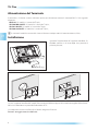
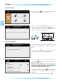
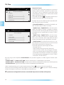
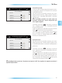
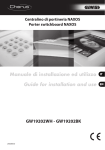
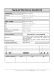
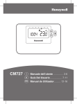
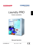
TH PLUS 24807130/26-02-2014 Manuale Tecnico IT Technical Manual EN TH Plus AVVERTENZE Le informazioni pubblicate nel presente manuale contengono diritti di Bpt S.p.a. a Socio Unico o dei suoi fornitori e non possono essere riprodotte in qualsiasi maniera né trasmesse ad altri. Le informazioni contenute nel presente manuale sono soggette a modifiche senza preavviso. Bpt S.p.a. non assume alcuna responsabilità per gli eventuali errori che il presente documento può contenere. Nessuna parte del presente manuale può essere riprodotta in qualsiasi forma o mezzo elettronico o meccanico, per alcun uso, senza il permesso scritto di Bpt S.p.a. a Socio Unico. ATTENZIONE IT • Leggere attentamente le istruzioni (disponibili in formato cartaceo o consultabili dal sito www.bpt.it) prima di iniziare l’installazione ed eseguire gli interventi come specificato dal costruttore; • Dopo aver tolto l’imballaggio assicurarsi dell’integrità dell’apparecchio; • Gli elementi dell’imballaggio (sacchetti in plastica, polistirolo espanso, ecc.) non devono essere lasciati alla portata dei bambini in quanto potenziali fonti di pericolo; • L’installazione, la programmazione, la messa in servizio e la manutenzione del prodotto deve essere effettuata soltanto da personale tecnico qualificato ed opportunamente addestrato nel rispetto delle normative vigenti ivi comprese le osservanze sulla prevenzione infortuni; • Operare in ambienti sufficientemente illuminati e idonei per la salute e utilizzare strumenti, utensili ed attrezzature in buono stato; • Non ostruire le aperture o fessure di ventilazione o di smaltimento di calore; • L’impianto elettrico dovrà essere realizzato in conformità con le normative in vigore nel paese di installazione; • Prima di collegare le apparecchiature alimentate a tensione di rete accertarsi che i dati di targa siano rispondenti a quelli della rete di distribuzione; • Le schede elettroniche possono essere seriamente danneggiate dalle scariche elettrostatiche: qualora vi sia bisogno di maneggiarle indossare idonei indumenti e calzature antistatiche o, almeno, assicurarsi preventivamente di aver rimosso ogni carica residua toccando con la punta delle dita una superficie metallica connessa all’impianto di terra (es. lo chassis di un elettrodomestico); • Al termine dell’installazione, verificare sempre il corretto funzionamento dell’apparecchiatura e dell’impianto nel suo insieme; • Prima di effettuare qualunque operazione di pulizia o di manutenzione, togliere l’alimentazione al dispositivo; nel caso di apparecchiature alimentate a tensione di rete togliere l’alimentazione, aprendo l’interruttore posto a monte dello stesso; • In caso di guasto e/o cattivo funzionamento di un dispositivo, distaccarlo dall’alimentazione e non manometterlo; • Per l’eventuale riparazione rivolgersi solamente ad un centro di assistenza tecnica autorizzato dal costruttore e comunque utilizzare sempre i ricambi forniti da Bpt S.p.A. a Socio Unico; • L’apparecchio dovrà essere destinato unicamente all’uso per il quale è stato espressamente concepito. • Il mancato rispetto delle prescrizioni sopra elencate può compromettere la sicurezza dell’apparecchio. Il costruttore non può comunque essere considerato responsabile per eventuali danni derivanti da usi impropri, erronei ed irragionevoli. 2 TH Plus INDICE AVVERTENZE . . . . . . . . . . . . . . . . . . . . . . . . . . . . . . . . . . . . . . . . . . . . . . . . . . . . . . . . . . . . . . . . . . . . . . . . . . . . . . . Pag. 2 L’ARCHITETTURA DEL SISTEMA . . . . . . . . . . . . . . . . . . . . . . . . . . . . . . . . . . . . . . . . . . . . . . . . . . . . . . . . Pag. 4 INSTALLAZIONE E MESSA IN SERVIZIO . . . . . . . . . . . . . . . . . . . . . . . . . . . . . . . . . . . . . . . . . . . . . . Pag. Caratteristiche tecniche . . . . . . . . . . . . . . . . . . . . . . . . . . . . . . . . . . . . . . . . . . . . . . . . . . . . . . . . . . . . . . . . . . . . . . . . . . . . . . Uso e manutenzione del Terminale . . . . . . . . . . . . . . . . . . . . . . . . . . . . . . . . . . . . . . . . . . . . . . . . . . . . . . . . . . . . . . . . . . Alimentazione del Terminale . . . . . . . . . . . . . . . . . . . . . . . . . . . . . . . . . . . . . . . . . . . . . . . . . . . . . . . . . . . . . . . . . . . . . . . . Installazione . . . . . . . . . . . . . . . . . . . . . . . . . . . . . . . . . . . . . . . . . . . . . . . . . . . . . . . . . . . . . . . . . . . . . . . . . . . . . . . . . . . . . . . . . . Funzione dei morsetti . . . . . . . . . . . . . . . . . . . . . . . . . . . . . . . . . . . . . . . . . . . . . . . . . . . . . . . . . . . . . . . . . . . . . . . . . . . . . . Funzione del pulsante S (Servizio) . . . . . . . . . . . . . . . . . . . . . . . . . . . . . . . . . . . . . . . . . . . . . . . . . . . . . . . . . . . . . . . . . . Funzione della porta USB . . . . . . . . . . . . . . . . . . . . . . . . . . . . . . . . . . . . . . . . . . . . . . . . . . . . . . . . . . . . . . . . . . . . . . . . . . . Funzione del pulsante R (RESET) . . . . . . . . . . . . . . . . . . . . . . . . . . . . . . . . . . . . . . . . . . . . . . . . . . . . . . . . . . . . . . . . . . . . Raccolta dispositivi . . . . . . . . . . . . . . . . . . . . . . . . . . . . . . . . . . . . . . . . . . . . . . . . . . . . . . . . . . . . . . . . . . . . . . . . . . . . . . . . . . Ricerca Manuale . . . . . . . . . . . . . . . . . . . . . . . . . . . . . . . . . . . . . . . . . . . . . . . . . . . . . . . . . . . . . . . . . . . . . . . . . . . . . . . . . . . . Ricerca Automatica . . . . . . . . . . . . . . . . . . . . . . . . . . . . . . . . . . . . . . . . . . . . . . . . . . . . . . . . . . . . . . . . . . . . . . . . . . . . . . . . . Configurazione dei dispositivi . . . . . . . . . . . . . . . . . . . . . . . . . . . . . . . . . . . . . . . . . . . . . . . . . . . . . . . . . . . . . . . . . . . . . . . Password . . . . . . . . . . . . . . . . . . . . . . . . . . . . . . . . . . . . . . . . . . . . . . . . . . . . . . . . . . . . . . . . . . . . . . . . . . . . . . . . . . . . . . . . . . . . Lingua . . . . . . . . . . . . . . . . . . . . . . . . . . . . . . . . . . . . . . . . . . . . . . . . . . . . . . . . . . . . . . . . . . . . . . . . . . . . . . . . . . . . . . . . . . . . . . Info dispositivo . . . . . . . . . . . . . . . . . . . . . . . . . . . . . . . . . . . . . . . . . . . . . . . . . . . . . . . . . . . . . . . . . . . . . . . . . . . . . . . . . . . . . Lista Dispositivi . . . . . . . . . . . . . . . . . . . . . . . . . . . . . . . . . . . . . . . . . . . . . . . . . . . . . . . . . . . . . . . . . . . . . . . . . . . . . . . . . . . . . Default . . . . . . . . . . . . . . . . . . . . . . . . . . . . . . . . . . . . . . . . . . . . . . . . . . . . . . . . . . . . . . . . . . . . . . . . . . . . . . . . . . . . . . . . . . . . . . Impostazioni . . . . . . . . . . . . . . . . . . . . . . . . . . . . . . . . . . . . . . . . . . . . . . . . . . . . . . . . . . . . . . . . . . . . . . . . . . . . . . . . . . . . . . . Impostazione termica . . . . . . . . . . . . . . . . . . . . . . . . . . . . . . . . . . . . . . . . . . . . . . . . . . . . . . . . . . . . . . . . . . . . . . . . . . . . . . . 7 7 7 8 8 9 9 9 9 11 12 12 13 16 16 16 16 16 17 17 3 IT TH Plus L’ARCHITETTURA DEL SISTEMA TH PLUS Bus di campo Alimentazione locale VAS/100MH OH/3RPI OH/PF IT SEC – + Made in Italy OH/PF LA TA/P1 TA/P1 PRI Esempio di collegamento con la sonda esterna OH/SRE TH PLUS OH/SRE VAS/100MH OH/PF OH/3RPI SEC – + Made in Italy OH/PF LA TA/P1 4 TA/P1 PRI TH Plus Nel sistema termico Multizona si possono aggiungere sonde termiche interne del tipo: - TA/P1: sonda di temperatura con display; - THPLUS: terminale con sonda di temperatura e umidità; - OH/SRI: sonda di temperatura e umidità; - OH/MT2: modulo per il collegamento di due sonde di temperatura. - OH/Z.02: modulo di controllo della temperatura di zona. È possibile collegare fino ad un massimo di 8 zone termiche interne ed una sonda di temperatura, umidità e pressione esterna OH/SRE, moduli di remotizzazione OH/GSM.01 oppure OH/ETH, moduli di espansione ingressi/uscite dei sistemi domotici BPT (OH/RI, OH/3RPI, ecc...) e il misuratore di energia OH/MPE6KW. IT Esempio di sistema a tre zone con sonda esterna Valvola Pompa ; ; TH PLUS OH/SRE VAS/100MH OH/3RPI SEC OH/PF – + Made in Italy OH/PF LA PRI TA/P1 TA/P1 5 TH Plus Esempio di sistema a sei zone con sonda esterna Valvola Pompa ; ; TH PLUS IT OH/SRE OH/3RPI OH/3RPI VAS/100MH SEC OH/PF OH/3RPI – + Made in Italy OH/PF LA PRI TA/P1 TA/P1 6 TA/P1 TA/P1 TA/P1 TH Plus INSTALLAZIONE E MESSA IN SERVIZIO Caratteristiche tecniche Il THplus è l’innovativo terminale Multizona che permette la visualizzazione di tutti i parametri termici (temperatura, umidità, condizione di comfort) delle singole zone controllate. Il dispositivo consente, se nel sistema è collegato anche un misuratore di energia OH/MPE6KW, di visualizzare il consumo di energia elettrica il consumo di energia elettrica e di visualizzare temperatura ed umidità esterna se presente il dispositivo OH/SRE. Il sistema può controllare fino ad un massimo di 8 zone termiche ed è composto da termostati di zona e da attuatori collegati tra loro tramite un bus a 2 fili non polarizzato. IT 25.6 112 166 Specifiche tecniche • Display 16:9 wide screen 4,3”, 480x272 pixel, touch screen. • Temperatura di funzionamento: da 5 °C a 40 °C. • Alimentazione: da BUS. • Assorbimento: 100 mA @17.5 V (con VAS100MH e VAS100.30); 100 mA @ 18 V (con VAS101); 90 mA @ 20 Vdc (con OH/A.01) • Dimensioni: 166 x 112 x 25.6 mm. Uso e manutenzione del Terminale ATTENZIONE • Per la pulizia utilizzare solo panni morbidi ed asciutti oppure leggermente inumiditi con acqua; non utilizzare alcun tipo di prodotto chimico. • Non esporre lo schermo LCD alla luce diretta del sole. 7 TH Plus Alimentazione del Terminale Il terminale e il relativo sistema mulrizona può essere alimentato tramite il morsetto BUS LA dai seguenti dispositivi: OH/A.01: 35 moduli e 1 terminale THplus; VAS100/MH+OH/PF: 15 moduli e 1 terminale THplus; VAS101+OH/PF: 35 moduli e 1 terminale THplus; VAS100.30+OH/PF: 35 moduli e 1 terminale THplus; IT Il numero di moduli massimo del sistema è limitato a 40 per motivi di comunicazione sul bus. Installazione Sganciare l’apparecchio dal supporto metallico, facendolo scorrere su di esso dopo aver premuto il pulsante plastico. 2 1 Fissare il supporto metallico alla scatola d’incasso tonda Ø 60 mm oppure alla scatola rettangolare 503 utilizzando le viti in dotazione e rispettando l’indicazione ALTO. La scatola deve essere installata ad un’altezza adeguata all’utente. Evitare il serraggio eccessivo delle viti. 8 TH Plus Funzione dei morsetti collegamento al BUS di sistema (non polarizzato) –1 2 collegamento alla sonda termica oppure ad un contatto (per indicazione di stato) A B collegamento al BUS per remotizzazione (RS485) B –1 A 2 L A IT Funzione del pulsante S (Servizio) SERVICE Il terminale è dotato di un pulsante per la ricerca dei dispositivi in Modalità Manuale. Funzione della porta USB USB Porta da utilizzare per la programmazione del terminale da tool e per effettuare aggiornamenti del software. RESET Funzione del pulsante R (RESET) Ogni volta che anomalie di funzionamento, interventi e altre ragioni tecniche richiedono il reset dell’apparecchio, premere leggermente il pulsante collocato all’interno dell’apertura indicata in figura; rilasciare il pulsante appena lo schermo si oscura e attendere che riappaia il menù principale prima di riprendere l’uso normale dell’apparecchio. Reset NOTA.Questa operazione NON comporta la cancellazione di eventuali programmi che saranno ripristinati, assieme agli altri dati, al riavvio dell’apparecchio. ATTENZIONE Una volta eseguiti i cablaggi reinserire attentamente le morsettiere come indicato in figura. 9 TH Plus IT Per sganciare l’apparecchio dal supporto metallico premere il gancio plastico e sollevare il terminale. 2 1 10 TH Plus Raccolta dispositivi Nella fase iniziale è possibile avviare la ricerca dei dispositivi in modalità automatica oppure manuale. IT 1 Dalla home page premere sull’ icona vamente sull’ icona . Configurazione Impostazione termica Eventi Consumi e successi- Impostazioni 2 Premere l’icona e inserire la password installatore (default 8765) per accedere al menù di Installazione. Lingue Password Info dispositivo Installazione Configurazione 3 PASSWORD Una volta inserita la password confermare premendo . 4 11 TH Plus Ricerca Manuale Premere sull’icona per avviare la raccolta manuale dei dispositivi collegati all’impianto. Ricerca Manuale Ricerca Automatica Installazione IT Default Lista dispositivi 5 RICERCA MANUALE Premere i pulsanti di service dei dispositivi collegati all’impianto... Premere il pulsante ‘Service’ 1 (per il TA/P1 preC i tasti mere contemporaneamente 2) di tutti i 1 I3 dispositivi presenti NA Made in Italy nell’impianto (esclusoù il termiI2 nale) per eseguire l’apprendimento. I1 C LA 67600700 OH/3RPI 1 SERVICE 2 C NA 3 C NA 2 6 Ricerca Automatica RICERCA AUTOMATICA Rilevamento dei dispositivi in corso... In questa modalità, il terminale ricercherà i dispositivi presenti nell’impianto e assegnerà loro un indirizzo. Premere sull’icona per avviare la raccolta automatica dei dispositivi collegati all’impianto. 7 Lista dispositivi 3 (1) TH+ Id: 070013E15001 1 (2) OHZ Id: 02289BE90200 2 (3) TAP1 Id: 070014053301 8 12 3 4 Terminata la fase di ricerca nelle due modalità, premere l’icona per visualizzare l’elenco dei dispositivi rilevati (figura 8). NOTA. Il numero 3 indica il numero progressivo di raccolta del dispositivo. mentre 4 indica l’indirizzo assegnato al dispositivo. Visualizzato l’elenco, premere , per confermare e procedere con la configurazione dei singoli dispositivi. Per tornare al menù precedente premere . TH Plus Configurazione dei dispositivi Configurazione dispositivi in/out 5 Proprietà 6 Ingressi e Uscite Dal menù ‘Lista dispositivi’ è possibile personalizzarne il nome e abilitare/disabilitare i relativi ingressi e assegnare una funzione alle uscite Gli ingressi abilitati verranno segnalati nella lista eventi del Menù Utente in caso di cambio stato. Per ogni modulo è possibile personalizzare il nome delle singole uscite cliccando l’icona 5. 1 OH3RPI (ID: 028ABB000700) Cucina Verrà visualizzata la tastiera necessaria per personalizzare il nome (figura 2). Premere , per confermare e procedere con la configurazione dei singoli dispositivi. Per tornare al menù precedente senza salvare alcuna impostazione premere . 2 Proprietà Valvola Pompa Generatore 3 Cliccando sulle icone è possibile visualizzare tutti i dispositivi aventi ingressi e/o uscite configurabili. Per modificare il dispositivo associato alla singola uscita spuntare la casella corrispondente 6. Verrà visualizzata la schermata di figura 3. Per ogni uscita è possibile scegliere quale dispositivo associarvi: Valvola ; Pompa ; Generatore ; Controllo Umidità . Scelto il dispositivo da associare all’uscita premere l’icona per tornare al menù precedente (figura 2). Terminata la fase di configurazione degli Ingressi e delle Uscite, premere l’icona per passare al menù di configurazione dei dispositivi termici. 13 IT TH Plus Configurazione dispositivi termici TA+ (Id: 070013E15001) Proprietà Soglia T sup Soglia T inf Dispositivi Termici In questo menù è possibile configurare i dispositivi termici (sonde termiche, termostati di zona, terminali THPLUS, ecc..) e specificare se nella zona scelta sono collegate all’ingresso Aux delle sonde remote oppure dei contatti finestra. Cliccando sulle icone è possibile selezionare un dispositivo termico presente nell’impianto. Sonda Remota Per ogni zona termica dell’impianto è possibile abilitare una o più di queste funzioni. 4 IT - ‘Controllo Umidità’ per controllare il livello di umidità sulla zona scelta (THPLUS e OHSRI); Configurazione sonda termica TH+ Sonda Remota Proprietà Sonda aux BPT Sonda aux PT1000 Sonda ext BPT 5 - ‘Soglia H sup’ e ‘Soglia H inf’ per attivare un controllo sulle soglie di umidità Superiore e Inferiore. Questi parametri sono impostabili dal ‘Menù Utente’ e possono attivare segnalazioni di evento (THPLUS e OHSRI). - ‘Soglia T sup’ e ‘Soglia T inf’per attivare un controllo sulle soglie di temperatura Superiore e Inferiore. Questi parametri sono impostabili dal ‘Menù Utente’ e possono attivare segnalazioni di evento. - ‘Sonda remota’ da utilizzare nel caso in cui si voglia controllare la temperatura da una sonda remota e non dalla sonda interna al dispositivo. È possibile utilizzare questo ingresso come: - contatto finestra; - sonda remota, come principale (Sonda ext); - sonda ausiliaria (Sonda aux) per leggere la temperatura a pavimento, oppure la temperatura remota. Questo tipo di sonda non è utilizzata per il controllo e il conseguente pilotaggio di un relè (THPLUS OHSRI TAP1 OHSRE OHMT2). Nel caso venga scelta l’opzione ‘Sonda Remota’ sarà possibile scegliere una delle seguenti funzioni (morsetto 1-2): - ‘Sonda aux BPT’ e ‘Sonda aux PT1000’: sonde utilizzate per il riscaldamento a pavimento; - ‘Sonda ext BPT’ e ‘Sonda ext PT1000’: sonde esterne utilizzate al posto della sonda interna del dispositivo; - ‘Contatto finestra’: ingresso utilizzato per inibire il controllo termico della zona. Scelta la configurazione per la sonda remota premere l’icona per tornare al menù precedente. Terminata la fase di configurazione dei dispositivi termici, premere l’icona per passare al menù di configurazione dei dispositivi termici per il controllo invernale ed estivo. m I paramentri configurabili variano a seconda del dispositivo installato nell’impianto. 14 TH Plus Configurazione controllo invernale TH+ (Id: 70BD62C1) Proprietà 6 Configurazione controllo estivo TH+ (Id: 70BD62C1) Proprietà 7 Controllo Invernale Al termine della configurazione dei dispositivi termici è possibile associare a tali dispositivi, le uscite per il controllo invernale. Alla zona termica è possibile associare, per il controllo termico invernale, valvole, pompe, caldaie e dispostivi per il controllo dell’umidità se presenti nell’impianto. m E’ possibile associare una sola uscita con funzione ‘valvola’ per ciascun dispositivo per una singola stagione Cliccando sulle icone è possibile visualizzare tutti i dispositivi termici per il controllo invernale presenti nell’impianto. Scelto il dispositivo di controllo invernale premere l’icona per tornare al menù precedente. Terminata la fase di configurazione dei dispositivi per il controllo invernale, premere l’icona per passare al menù di configurazione dei dispositivi termici per il controllo estivo. Controllo Estivo Alla zona termica è possibile associare, per il controllo termico estivo, valvole, pompe, dispostivi per il controllo dell’umidità se presenti nell’impianto e generatori. Cliccando sulle icone è possibile visualizzare tutti i dispositivi termici per il controllo estivo presenti nell’impianto. Scelto il dispositivo di controllo estivo premere l’icona per tornare al menù precedente (figura 16). Al termine della configurazione dei dispositivi termici, l’impianto risulta configurato; per tornare alla schermata iniziale premere l’icona . m A configurazione terminata, l’impianto verrà posto in OFF. Per scegliere la stagione consultare il capitolo ‘Impostazioni’ 15 IT TH Plus Password Lingue Password Info dispositivo Installazione Configurazione Premere sull’icona per accedere alla schermata che permette di modificare la password. Premere sull’icona per modificare la Password Installatore (default 8765) oppure sull’icona per modificare quella Utente (default 1234). La password può essere composta al massimo da 15 caratteri alfanumerici. 8 IT Lingua Premere sull’icona per cambiare la lingua. Info dispositivo Installatore Utente Password Premere sull’icona software installata. per verificare la versione del Lista Dispositivi Premere l’icona inserire la password Installatore (default 8765). Premere sull’icona per visualizzare i dispositivi installati nell’impianto. 9 Default Ricerca Manuale Ricerca Automatica Installazione Default 10 16 Lista dispositivi Premere sull’icona per ripristinare la configurazione dell’impianto (non le impostazioni scelte nel Menù Utente). TH Plus Impostazioni Impostazione termica Dal menù iniziale premere sull’icona e successivamente premere sull’icona per scegliere la modalità di funzionamento dell’intero impianto (fig. 3). Configurazione Impostazione termica Impostazioni Pone l’impianto in modalità Raffrescamento Pone l’impianto in modalità Riscaldamento Eventi Consumi 1 Ll’impianto è in modalità Antigelo: questa icona sarà visibile quando tutte le zone sono in OFF e l’impianto è in modalità Riscaldamento. Il controllo sull’impianto di termoregolazione viene TOTALMENTE disabilitato. Configurazione Impostazione termica Eventi Consumi Estate Inverno Impostazioni 2 Impostazione Termica m Premendo il pulsante oltre a disabilitare il controllo sull’impianto di termoregolazione si disabilita anche la funzione che protegge l’impianto dalle gelate (funzione antigelo). Nel caso in cui l’impianto sia posto in OFF, agendo sulla singola zona per scegliere la modalità di funzionamento (Jolly, Manuale o Automatico) apparirà il POPUP riportato di seguito. Confermando apparirà il menù rappresentato in figura 3; scegliere la stagione e procedere con la programmazione. ATTENZIONE! Impostare prima una stagione Impostare ora? Off OK Annulla 3 Estate Impostazione Termica Inverno Off 4 17 IT TH Plus SMALTIMENTO Assicurarsi che il materiale d’imballaggio non venga disperso nell’ambiente, ma smaltito seguendo le norme vigenti nel paese di utilizzo del prodotto. Alla fine del ciclo di vita dell’apparecchio evitare che lo stesso venga disperso nell’ambiente. Lo smaltimento dell’apparecchiatura deve essere effettuato rispettando le norme vigenti e privilegiando il riciclaggio delle sue parti costituenti. Sui componenti, per cui è previsto lo smaltimento con riciclaggio, sono riportati il simbolo e la sigla del materiale. IT Eventuali aggiornamenti del presente documento sono disponibili sul sito www.bpt.it. Il produttore si riserva il diritto di apportare qualsiasi modifica al prodotto al fine di migliorarne le funzionalità. 18 TH Plus IT 19 TH Plus WARNINGS The information in this manual is covered by the rights of Bpt S.p.a. a Socio Unico or its suppliers and may not be reproduced in any way, nor transmitted to others. The information in this manual is subject to change without advance notice. Bpt S.p.a. shall not be held liable for any errors which this document may contain. No part of this manual may be reproduced in any mechanical or electronic form or means, for any use, without the written permission of Bpt S.p.a. a Socio Unico. WARNING EN • Read the instructions (available in hard copy or to be found on the website www.bpt.it) carefully before beginning the installation and carry out the actions as specified by the maker; • After removing the packaging check the condition of the unit; • The packaging (plastic bags, expanded polystyrene, etc.) must not be left within reach of children, as they are potentially dangerous; • The installation, programming, putting into operation and maintenance of the product must be carried out only by qualified technical personnel, correctly trained with regard to respecting the regulations in force, including the implementation of accident prevention measures; • Work in areas that are adequately lit and conducive to health, and use instruments, tools and equipment that are in good condition; • Do not obstruct the ventilation or heat dissipation openings or slots; • The electrical system must be created in compliance with the regulations in force in the country of installation; • Before connecting equipment powered at network voltage make sure that the data on the name plate correspond with those of the distribution network; • The electronic circuit boards can be seriously damaged by electrostatic discharge: before handling them put on suitable clothing and anti-static shoes or, at least, first make sure you have removed any residual charge by touching the tips of your fingers to a metal surface connected to the earthing system (e.g. the framework of an electrical appliance); • When installation is completed, always check that the equipment, and the complete system, works correctly; • Before carrying out any cleaning or maintenance operation, disconnect the device from the power supply; for equipment powered at network voltage, disconnect from the power supply, turning the switch located upstream from it; • In the event of a breakdown and/or malfunction of a device, disconnect it from the power supply and do not tamper with it; • For any eventual repairs contact only a technical service centre authorised by the manufacturer and always use the parts supplied by BPT S.p.a. a socio Unico; • The equipment must be destined solely for the use for which it was expressly designed. • Failure to comply with the above instructions may compromise the unit’s safety. The manufacturer declines all liability for any damage as a result of improper, incorrect or unreasonable use. 2 TH Plus CONTENTS WARNINGS . . . . . . . . . . . . . . . . . . . . . . . . . . . . . . . . . . . . . . . . . . . . . . . . . . . . . . . . . . . . . . . . . . . . . . . . . . . . . . . . Page 2 SYSTEM ARCHITECTURE . . . . . . . . . . . . . . . . . . . . . . . . . . . . . . . . . . . . . . . . . . . . . . . . . . . . . . . . . . . . . . . Page 4 INSTALLATION AND PUTTING INTO OPERATION . . . . . . . . . . . . . . . . . . . . . . . . . . . . . . . . Page 7 Technical Features . . . . . . . . . . . . . . . . . . . . . . . . . . . . . . . . . . . . . . . . . . . . . . . . . . . . . . . . . . . . . . . . . . . . . . . . . . . . . . . . . . . 7 Use and maintenance of Terminal . . . . . . . . . . . . . . . . . . . . . . . . . . . . . . . . . . . . . . . . . . . . . . . . . . . . . . . . . . . . . . . . . . . 7 Power supply to Terminal . . . . . . . . . . . . . . . . . . . . . . . . . . . . . . . . . . . . . . . . . . . . . . . . . . . . . . . . . . . . . . . . . . . . . . . . . . . . 8 Installation . . . . . . . . . . . . . . . . . . . . . . . . . . . . . . . . . . . . . . . . . . . . . . . . . . . . . . . . . . . . . . . . . . . . . . . . . . . . . . . . . . . . . . . . . . . 8 Function of terminals . . . . . . . . . . . . . . . . . . . . . . . . . . . . . . . . . . . . . . . . . . . . . . . . . . . . . . . . . . . . . . . . . . . . . . . . . . . . . . . 9 Function of button S (Service) . . . . . . . . . . . . . . . . . . . . . . . . . . . . . . . . . . . . . . . . . . . . . . . . . . . . . . . . . . . . . . . . . . . . . . 9 Function of USB port . . . . . . . . . . . . . . . . . . . . . . . . . . . . . . . . . . . . . . . . . . . . . . . . . . . . . . . . . . . . . . . . . . . . . . . . . . . . . . . 9 Function of button R (RESET) . . . . . . . . . . . . . . . . . . . . . . . . . . . . . . . . . . . . . . . . . . . . . . . . . . . . . . . . . . . . . . . . . . . . . . . 9 Device search . . . . . . . . . . . . . . . . . . . . . . . . . . . . . . . . . . . . . . . . . . . . . . . . . . . . . . . . . . . . . . . . . . . . . . . . . . . . . . . . . . . . . . . . 11 Manual Search . . . . . . . . . . . . . . . . . . . . . . . . . . . . . . . . . . . . . . . . . . . . . . . . . . . . . . . . . . . . . . . . . . . . . . . . . . . . . . . . . . . . . . 12 Automatic Search . . . . . . . . . . . . . . . . . . . . . . . . . . . . . . . . . . . . . . . . . . . . . . . . . . . . . . . . . . . . . . . . . . . . . . . . . . . . . . . . . . . 12 Configuration of devices . . . . . . . . . . . . . . . . . . . . . . . . . . . . . . . . . . . . . . . . . . . . . . . . . . . . . . . . . . . . . . . . . . . . . . . . . . . . . 13 Password . . . . . . . . . . . . . . . . . . . . . . . . . . . . . . . . . . . . . . . . . . . . . . . . . . . . . . . . . . . . . . . . . . . . . . . . . . . . . . . . . . . . . . . . . . . . 16 Language . . . . . . . . . . . . . . . . . . . . . . . . . . . . . . . . . . . . . . . . . . . . . . . . . . . . . . . . . . . . . . . . . . . . . . . . . . . . . . . . . . . . . . . . . . . 16 Info device . . . . . . . . . . . . . . . . . . . . . . . . . . . . . . . . . . . . . . . . . . . . . . . . . . . . . . . . . . . . . . . . . . . . . . . . . . . . . . . . . . . . . . . . . . 16 List of devices . . . . . . . . . . . . . . . . . . . . . . . . . . . . . . . . . . . . . . . . . . . . . . . . . . . . . . . . . . . . . . . . . . . . . . . . . . . . . . . . . . . . . . . 16 Default . . . . . . . . . . . . . . . . . . . . . . . . . . . . . . . . . . . . . . . . . . . . . . . . . . . . . . . . . . . . . . . . . . . . . . . . . . . . . . . . . . . . . . . . . . . . . . 16 Setup . . . . . . . . . . . . . . . . . . . . . . . . . . . . . . . . . . . . . . . . . . . . . . . . . . . . . . . . . . . . . . . . . . . . . . . . . . . . . . . . . . . . . . . . . . . . . . . 17 Thermal setting . . . . . . . . . . . . . . . . . . . . . . . . . . . . . . . . . . . . . . . . . . . . . . . . . . . . . . . . . . . . . . . . . . . . . . . . . . . . . . . . . . . . . 17 3 EN TH Plus SYSTEM ARCHITECTURE TH PLUS Field bus Local power supply VAS/100MH OH/3RPI OH/PF SEC – + Made in Italy OH/PF LA TA/P1 EN TA/P1 PRI Example of connection with OH/SRE external sensor TH PLUS OH/SRE VAS/100MH OH/PF OH/3RPI SEC – + Made in Italy OH/PF LA TA/P1 4 TA/P1 PRI TH Plus The Multizone thermal system can be used with internal temperature sensors of type: - TA/P1: temperature sensor with display: - THPLUS: terminal with temperature and humidity sensor; - THPLUS: terminal with temperature and humidity sensor; - OH/MT2: module to connect two temperature sensors. - OH/Z.02: zone temperature control module. It is possible to connect up to a maximum of 8 internal temperature zones and an OH/SRE temperature, humidity and external pressure sensor, OH/GSM.01 or OH/ETH remote access modules, input/output expansion modules for BPT home automation systems (OH/RI, OH/3RPI, etc...) and the OH/MPE6KW energy measuring device. EN Example of a three-zone system with external sensor Valve Pump ; ; TH PLUS OH/SRE VAS/100MH OH/3RPI SEC OH/PF – + Made in Italy OH/PF LA PRI TA/P1 TA/P1 5 TH Plus Example of a six-zone system with external sensor Valve Pump ; ; TH PLUS OH/SRE EN OH/3RPI OH/3RPI VAS/100MH SEC OH/PF OH/3RPI – + Made in Italy OH/PF LA PRI TA/P1 TA/P1 6 TA/P1 TA/P1 TA/P1 TH Plus INSTALLATION AND PUTTING INTO OPERATION Technical Features The THplus is the innovative Multizone terminal that enables all the thermal parameters (temperature, humidity, comfort) of the individual zones controlled to be displayed. If an OH/MPE6KW energy measuring device is also connected to the system the consumption of electric power can be displayed, and also the temperature and external humidity, if an OH/SRE device is connected. The system can control up to a maximum of 8 thermal zones and is made up of zone thermostats and actuators connected to each other via an unpolarised bus with 2 cables. 25.6 EN 112 166 Technical specifications • 16:9 wide screen 4.3”, 480x272 pixel, touch screen display. • Operating temperature: from 5 °C to 40 °C • Power supply: by BUS. • Consumption: 100 mA @17.5 V (with VAS100MH and VAS100.30); 100 mA @ 18 V (with VAS101); 90 mA @ 20 Vdc (with OH/A.01) • Dimensions: 166 x 112 x 25.6 mm. Use and maintenance of Terminal WARNING • Only use soft, dry or slightly damp cloths to clean the terminal; do not use any chemical products. • Do not expose the LCD screen to direct sun light. 7 TH Plus Power supply to Terminal The terminal and the related multizone system can be powered via the BUS LA terminal from the following devices: OH/A.01: 35 modules and 1 THplus terminal; VAS100/MH+OH/PF: 15 modules and 1 THplus terminal; VAS101+OH/PF: 35 modules and 1 THplus terminal; VAS100.30+OH/PF: 35 modules and 1 THplus terminal; The system's maximum number of modules is limited to 40 for reasons to do with communication on the bus. Installation Unfasten the equipment from the metal support by letting it run smoothly along it after you have pressed the plastic button. EN 2 1 Fix the metal support to the round Ø 60 mm back-box or the rectangular 503 back-box using the screws provided and paying attention to the UP direction indication, The box must be installed at an appropriate height for the user. Avoid tightening the screws too much. 8 TH Plus Function of terminals connection to system BUS (unpolarised) –1 2 connection to temperature sensor or to a contact (for status indication) A B connection to BUS through remote access (RS485) B –1 A 2 L A EN Function of button S (Service) SERVICE The terminal is provided with a button to search for devices in Manual Mode. Function of USB port USB Port to be used for programming the terminal with the tool and for making updates to the software. RESET Function of button R (RESET) Any time that operating anomalies, servicing or other technical reasons require the unit to be reset, press lightly on the button located inside the opening shown in the figure; release the button as soon as the screen goes dark and wait for the main menu to reappear before resuming normal use of the unit. Reset NOTE. This operation does NOT delete any programmes, which will be restored, along with other data, when the unit is restarted. WARNING Once the cabling has been done, carefully reinsert the terminal blocks as shown in the figure. 9 TH Plus EN To unfasten the unit from the metal support press the plastic button and lift the terminal. 2 1 10 TH Plus Device search In the initial phase it is possible to start up the search for devices in either automatic or manual mode. EN 1 On the home page press on icon icon . Configuration Thermal setting Events Energy and then on Setup 2 Press icon and enter the installer password (default 8765) to access the installation menu. Languages Password Info device Installation Configuration 3 PASSWORD Once the password has been entered confirm by pressing . 4 11 TH Plus Manual Search Press on icon to start up manual search of the devices connected to the system. Manual Search Automatic Search Installation EN Default List of devices 5 MANUAL SEARCH Press service buttons of devices connected to system... Press the ‘Service’ button 1 (for the TA/P1 at the same time press keys 1 C2) of all the devices preI3 sent in the system Made in Italy (apart NA from the terminal) for autoI2 recognition to take place. I1 C LA 67600700 OH/3RPI 1 SERVICE 2 C NA 3 C NA 2 6 Automatic Search AUTOMATIC SEARCH In this mode, the terminal will search for the devices present on the system and assign them an address. Press on icon to start up automatic search of the devices connected to the system. Device detection in progress... 7 List of devices 3 (1) TH+ Id: 070013E15001 1 (2) OHZ Id: 02289BE90200 2 (3) TAP1 Id: 070014053301 8 12 3 4 Once the search phase is completed in the two modes, press icon to display the list of devices detected (figure 8). NOTE. The number 3 indicates the progressive search number of the device, while 4 indicates the address assigned to the device. Once the list is displayed, press to confirm and proceed with the configuration of the individual devices. Press to go back to the previous menu. TH Plus Configuration of devices In/out devices configuration 5 Properties 6 Inputs and Outputs From the ‘List of devices’ menu you can customise the name and enable/disable the relative inputs and assign a function to the outputs The enabled inputs will be marked on the events list of the User Menu if there is a change in status. For each module the name of the individual outputs can be customised by clicking on icon 5. 1 OH3RPI (ID: 028ABB000700) Kitchen The keyboard required to customise the name will be displayed (figure 2). Press to confirm and proceed with the configuration of the individual devices. To go back to the previous menu without saving any settings, press . 2 Properties Valve Pump Generator 3 By clicking on icons it is possible to display all the devices with inputs and/or outputs that can be configured. To change the device associated to an individual output, check the corresponding box 6. The screen in figure 3 will be displayed. You can choose which device to associate to each output: Valve ; Pump ; Generator ; Humidity control . Once the device to be associated to the output has been chosen, press icon to go back to the previous menu (figure 2). Once the configuration of inputs and outputs phase has been completed, press icon to move to the thermal devices configuration menu. 13 EN TH Plus Thermal devices configuration TA+ (Id: 070013E15001) Properties Upper T threshold Lower T threshold Thermal Devices On this menu you can configure the thermal devices (temperature sensors, zone thermostats, THPLUS terminals, etc.) and specify whether remote sensors or window contacts are connected to the Aux input in the zone selected. By clicking on icons you can select a thermal device that is present in the system. Remote Sensor One or more of these functions can be enabled for each of the system's thermal zones. 4 EN - ‘Humidity Control’ to control the level of humidity in the zone selected (THPLUS and OHSRI); Thermal sensor configuration TH+ Remote Sensor Properties BPT aux sensor PT1000 aux sensor BPT ext sensor 5 - ‘Upper H threshold’ and ‘Lower H threshold’ to activate an Upper and Lower humidity thresholds check. These parameters can be set from the 'User Menu' and can activate event warnings (THPLUS and OHSRI). - ‘Upper T threshold’ and ‘Lower T threshold’ to activate an Upper and Lower temperature thresholds check. These parameters can be set from the 'User Menu' and can activate event warnings. - ‘Remote sensor’ to be used when you want to check the temperature from a remote sensor and not from the sensor inside the device. This input can be used as: - window contact; - remote sensor, as the main one (External sensor); - auxiliary sensor (Aux sensor) to read the floor temperature, or the remote temperature. This type of sensor isn't used to control and operate a relay (THPLUS OHSRI TAP1 OHSRE OHMT2). If the option ‘Remote Sensor’ is chosen it will be possible to choose one of the following functions (terminal 1-2): - ‘BPT aux sensor’ and ‘PT1000 aux sensor’: sensors used for underfloor heating; - ‘BPT ext sensor’ and ‘PT1000 ext sensor’: external sensors used instead of the device's internal sensor; - ‘Window contact’: input used to block the thermal control of the zone. Once you have chosen the configuration for the remote sensor press icon to go back to the previous menu. Once the thermal devices configuration phase is completed, press icon to move to the thermal devices configuration menu for winter and summer control. m The parameters that can be configured vary according to the device installed on the system. 14 TH Plus Winter control configuration TH+ (Id: 70BD62C1) Properties 6 Summer control configuration TH+ (Id: 70BD62C1) Properties 7 Winter Control After completing the configuration of the thermal devices these devices can be associated to outputs for winter control. For winter thermal control valves, pumps, boilers and devices to control humidity, if present in the system, can be associated to the thermal zone. m A single output can be associated to the function 'valve' for each device for a particular season By clicking on icons all the thermal devices for winter control present in the system can be displayed. Once the winter control device has been chosen, press icon to go back to the previous menu (figure 2). Once the winter control devices configuration phase is completed, press icon to move to the thermal devices configuration menu for summer control. Summer Control For summer thermal control valves, pumps and devices to control humidity, if present in the system, can be associated to the thermal zone. By clicking on icons all the thermal devices for summer control present in the system can be displayed. Once the summer control device has been chosen, press icon to go back to the previous menu (figure 16). Once the thermal devices have been configured, the system is configured; to go back to the first screen press icon . m Once the configuration is completed, the system will be turned OFF. To choose the season look at the paragraph on 'Setup' 15 EN TH Plus Password Languages Password Info device Installation Configuration Press on icon to access the screen that lets you change the password. Press on icon to change the Installer Password (default 8765) or on icon to change the User Password (default 1234). The password can be made up of a maximum of 15 alphanumeric characters. 8 EN Language Press on icon to change the language. Info device Installer User Password Press on icon installed. to check the version of the software List of devices Press icon and enter the Installer password (default 8765). Press on icon to see the devices installed in the system. 9 Default Manual Search Automatic Search Installation Default 10 16 List of devices Press on icon to reset the system configuration (not the settings chosen from the User Menu). TH Plus Setup Thermal setting From the initial menu press on icon and then press on icon to choose the mode of operation of the whole system (fig. 3). Configuration Thermal setting Setup Places the system in Cooling mode Places the system in Heating mode Events Energy 1 The system is in Anti-frost mode: this icon will be visible when all the zones are OFF and the system is in Heating mode. Control of the heating regulation system is COMPLETELY disabled. m If you press button Configuration Thermal setting Events Energy Setup 2 Summer Thermal setting in addition to disabling the control of the heat regulation system, you will also disable the function that protects the system against freezing (anti-frost function). If the system is switched OFF, acting on the individual zone to choose the mode of operation (All-purpose, Manual or Automatic) will make the following POPUP appear. After confirmation, the menu shown in figure 3 will appear; choose the season and go on with the programming. Winter WARNING! First set a season Set now? Off OK Cancel 3 Summer Thermal setting Winter Off 4 17 EN TH Plus DISPOSAL Do not litter the environment with packaging material: make sure it is disposed of according to the regulations in force in the country where the product is to be used. When the equipment reaches the end of its life cycle, avoid discarding in the environment. The equipment must be disposed of in compliance with current regulations, recycling its component parts wherever possible Components that qualify as recyclable waste feature the relevant symbol and material acronym EN Updates to this manual are available on our website www.bpt.it. The manufacturer reserves the right to make changes to the product in order to improve its functionality. BPT S.p.A. a Socio Unico Via Cornia, 1/b 33079 Sesto al Reghena Pordenone - Italy tel. (+39) 0434 698111 fax (+39) 0434 698434 [email protected] - www.bpt.it Bpt is a company of 20