1
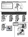
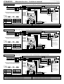
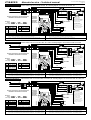
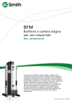
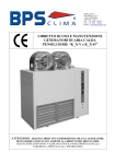
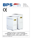
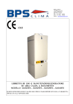
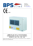
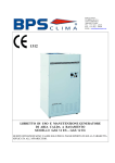
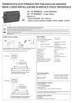
BPS S.r.l. - Via Biban (Zona Industriale), 56
31030 – CARBONERA ; TREVISO (ITALY)
Tel.: +39 0422-445363 r.a. - Fax.: +39 0422-398646
www.bpstecnologie.com
e-mail: [email protected]
Una linea completa di pannelli comando dedicati per installazione a
bordo unità che permette, spendendo poco di più, di avere tanto di più ...
A complete range of control panel dedicated to the unit’s on-board
installation which, with reasonable price, are offering much more…
CBE23
Manuale tecnico – Technical manual
Code: MT-CBE23- 80020132-R00
Page 1/5
COMPONENTI FORNITI
Quadro comando mod. CBE 23
(con OFF/Est/Inv + 3 velocità/auto + Termostato elettronico)
2 viti (A+B) per fissaggio staffa comando sull’unità
1 Clip (C) per fissaggio sensore temperatura sull’unità
1 Fascetta per cablaggio (D)
A+B
SUPPLIED ITEMS
Control panel mod. CBE 23
(with OFF/Sum/Win + 3 speed/auto + Electronic thermostat)
2 screws (A+B) to install the frame in the unit
1 Clip (C) to install the air temperature sensor in the unit
1 Cables tie (D)
D
Installare il quadro comando (2 viti: A+B)
Fissare la Clip (C) sul foro predisposto sulla carpenteria dell’unità
Infilare il sensore temperatura aria (stesso foro passaggio cavo motore)
Fissare il sensore temperatura aria sulla Clip (C) con la fascetta per cablaggio (D)
Inserire il connettore unidirezionale del quadro comando sull’autotrasformatore dell’unita
1
Install the control panel (2 screws: A+B)
Fix the Clip (C) in the suitable hole in the frame’s unit
Install the air temperature sensor (the same hole of motor cable)
Fix the air temperature sensor on the Clip (C) with cables tie (D)
Insert the control panel one-way plug on the unit’s autotransformer
2
3
4
A
B
C+D
C
Quadro comando
Control Panel
Dettaglio dei 3 Fori
(A+B+C) da usare
Detail of 2 holes
(A+B+C) to be used
165
95
5
A
Staffa - Bracket
CLAK!
55
4=B
1 2 3 4 5 6 7 8 9
T
N
Ph
Autotrasformatore
Autotransformer
C
87
77
1
2
3
4
5
C
127
CBE23
Manuale tecnico – Technical manual
Code: MT-CBE23- 80020132-R00
Page 2/5
Comando a bordo unità a microprocessore AUTOMATICO con funzione
antistratificazione + 3 Velocità manuali/auto + OFF/Estate/Inverno +
Termostato ambiente elettronico + Sonda temperatura aria
AUTOMATIC microprocessor control panel with anti-stratification function
+ 3 Speed manual/auto + OFF/Summer/Winter + Electronic room
thermostat + Air temperature sensor.
Comando configurabile, idoneo per la gestione di unità a 2 tubi e 4
tubi (con deviazione Estate/Inverno solo manuale).
Questo comando controlla unità con e senza termostato di minima
temperatura acqua “TM” (Il “TM” è un accessorio addizionale).
Questo comando è adatto per comandare:
“Unità a 3 velocità senza valvole” - “Unità a 3 velocità + 1
elettrovalvola 230V ON/OFF” - “Unità a 3 velocità + 2 elettrovalvole
230V ON/OFF”.
Range di temperature del set-point regolabile (Blocco manopola).
Funzione antistratificazione attivabile/disattivabile.
Possibilità di impostare 2 diverse configurazioni: “motore termostatato +
valvole termostatate” oppure “solo le valvole termostatate, con
motore sempre acceso”.
Distanza tra le velocità automatiche impostabile/modificabile.
Configurable control panel, suitable to control 2 and 4 pipes system
units (with only manual Summer/Winter switch).
This control panel can control units with or without “TM” water low
temperature thermostat (The “TM” is an additional option).
This control panel is suitable to control:
“3-speed unit without valves” - “3-speed unit + 1 ON/OFF 230V valve”
- “3-speed unit + 2 ON/OFF 230V valves”.
Adjustable set-point temperature range (Blockage knob).
Anti-stratification function active / not active.
Possibility to set 2 different: “Motor + valves controlled by thermostat” or
“Valves (only) controlled by thermostat, with motor always running”.
Gap between the speed settable/modifiable.
CARATTERISTICHE ELETTRICHE - ELECTRICAL FEATURES
Alimentazione elettrica
Power supply
Potenza assorbita
Power absorption
Campo di regolazione
Regulation range
Tipo di sensore
Sensor type
Precisione
Accuracy
Risoluzione
Resolution
Isteresi
Hysteresis
Portata contatti
Contact rating
Grado di protezione
Protection grade
Distanza tra le velocità (auto)
Gap between the speed (auto)
Antistratificazione
Anti-stratification
Temperatura di funzionamento
Temperatura di stoccaggio
Limiti di umidità
Contenitore
Norme di riferimento EMC
Norme di riferimento LVD
Operating temperature
Storage temperature
Humidity limits
Case
EMC reference norms
LVD reference norms
230V~ -15% +10% / 1 Ph / 50 Hz
7,7 VA (rif./ref. 230V~)
5 °C ... 35 °C
Sonda remota / Remote sensor NTC 4.700 Ohm @ 25°C ±1% ; L=1m ; connettore/connector JST
± 1,5 °C
1 °C
0,4 °C
3 (1) A @ 250V~ SPDT
IP 20
0,4 °C – 0,6 °C – 0,8 °C (impostabile – settable)
Attiva il motore ogni 15 minuti per 90 secondi, alla velocità min.
Activate the motor every 15 minutes for 90 seconds, to the minimum speed
0 °C ÷ +40 °C
-10 °C ÷ +50 °C
20 % ÷ 80 % U.R. – R.H. (senza condensa - non condensing)
ABS
CEI-EN 55014-2 ; CEI-EN 55014-1
CEI-EN 60335-1
CARATTERISTICHE FUNZIONALI
I comandi disponibili sul fronte del quadro comando per l’utente sono 2
selettori ed 1 manopola.
FUNCTIONAL FEATURES
The controls available on the front cover of the user’s control board are 2
sliders and 1 knob.
Manopola di regolazione
Tramite la manopola di regolazione è possibile impostare la temperatura
attorno a cui verrà effettuato il controllo della temperatura desiderata,
all’interno del campo di lavoro/regolazione previsto.
Range di temperature del set-point regolabile: Un sistema di blocco a
cavalieri prevosto sotto la manopola, permette di definire il campo di
temperatura entro il quale il termostato può funzionare.
Selettore OFF/Estate/Inverno (Ventola/Off/Fiamma)
Tramite questo selettore a 3 posizioni si può attivare il termostato in modo
riscaldamento (Fiamma), raffreddamento (Ventola) o disattivare il
termostato in modo funzionale (0).
Selettore velocità motore
Tramite questo selettore a 4 posizioni si può scegliere una delle 3 velocità
(fisse) di attivazione del motore dell’unità oppure la funzione “AUTO”.
In posizione “AUTO” le 3 velocità del motore cambiano
automaticamente al variare della temperatura ambiente.
Se il jumper “JP5” è inserito il motore non è termostatato con la valvola, e
rimane sempre acceso alla velocità selezionata: in questo caso, se il
selettore è in posizione “AUTO” il motore cambia le velocità
automaticamente ma non si spegne rimanendo al minimo in velocità
min. I Jumper “JP3” e “JP4” permettono di impostare il differenziale tra le
3 velocità.
Sonda esterna
Questo quadro comando è dotato di sonda di rilevazione temperatura
aria ambiente esterna/remota, installata sulla ripresa aria dell’unità.
Funzione dei ponti/Jumper
Regulation knob
Through the temperature set-point knob, the user can set the wished
room temperature, within the available temperature range.
Adjustable set-point temperature range: under the knob is installed a plug
enabling to fix working range temperature of the thermostat.
Tipo di impianto (JP1 – JP2):
JP1 inserito : impianto 2 tubi con 1 valvola o senza valvola
JP2 inserito : impianto 4 tubi con 2 valvole
Impostazione JP1-JP2 in fabbrica a seconda del tipo di impianto ed
altri accessori installati (vedi schemi elettrici)
Type of installation (JP1 – JP2):
JP1 inserted : 2 pipe installation with or without valve
JP2 inserted: 4 pipe installation with 2 valves
JP1 – JP2 are factory set according with installation type and
according with other installed accessories (see wiring diagrams)
Distanza tra le velocità automatiche (JP3 – JP4):
JP3 inserito : distanza 0,6°C tra le velocità
JP4 inserito : distanza 0,4°C tra le velocità (impostazione standard
di fabbrica, salvo diversa specifica richiesta)
JP3 e JP4 non inseriti : distanza 0,8°C tra le velocità
Gap between the automatic speed (JP3 – JP4):
JP3 inserted : gap between speed 0,6°C
JP4 inserted : gap between speed 0,4°C (standard factory set
value, if not differently specified)
JP3 and JP4 not inserted : gap between speed 0,8°C
Antistratificazione (JP5 – JP6 – JP7):
JP5 inserito : motore non termostatato (sempre attivo)
JP6 inserito : antistratificazione OFF (impostazione standard di
fabbrica, salvo diversa specifica richiesta)
JP7 inserito : antistratificazione ON
Anti-stratification (JP5 – JP6 – JP7):
JP5 inserted : not thermostated motor (always running)
JP6 inserted : anti-stratification OFF (standard factory set value, if
not differently specified)
JP7 inserted : anti-stratification ON
OFF/Summer/Winter selector (Fan/Off/Flame)
Through this 3-position slide selector, the user can chose heating (Flame),
cooling (Fan) or deactivate the thermostat function (0).
Speed motor selector
Through this 4-position slide selector, the user can chose the (fixed) speed
of the unit’s motor or “AUTO” mode.
In “AUTO” position the 3 motor’s speed change automatically according
with room temperature changes.
If the “JP5” jumper is inserted the motor is not thermostated with the valve
and is kept running to the selected speed: in this case, if the selector is in
“AUTO” position the motor automatically changes speed, but it’s not
switched-off remaining to the minimum speed. “JP3” and “JP4” jumper
enable to set the gap between the 3 speed.
External sensor
This control panel is equipped of external/remote air temperature sensor,
installed on the unit’s air intake.
Jumpers/bridges function
CBE23
Manuale tecnico – Technical manual
Code: MT-CBE23- 80020132-R00
Page 3/5
Funzione antistratificazione
Con il ponte inserito su “JP5” il motore è sempre attivo ; con il ponte
inserito su “JP6” la funzione antistratificazione è disattivata ; con il ponte
inserito su “JP7” la funzione antistratificazione è attivata.
Questa funzione serve per rilevare la corretta temperatura dell’aria della
stanza, anche quando il motore è fermo da molto tempo.
Quando è prevista la funzione ventilazione termostatata e si raggiunge la
temperatura di set-point, il ventilatore si ferma e, per effetto della
stratificazione dell’aria, la temperatura rilevata dalla sonda sarà diversa
da quella effettiva/reale dell’ambiente (percepita dalle persone).
Con la funzione antistratificazione attivata, quanto il ventilatore è spento
per raggiungimento del set-pont, ogni 15 minuti viene comunque attivata
la ventilazione per 90 secondi alla velocità min. indipendentemente dalla
termostatazione, la sonda rileva la corretta temperatura dell’aria
ambiente, la confronta con la temp. di set-point e di conseguenza il
comando decide se fermare od attivare l’unità.
Uscite valvole riscaldamento (fiamma) e condizionamento (ventola)
Anti-stratification function
With the jumper in “JP5” position the motor always running ; with the
jumper in “JP6” position the anti-stratification function is not active ; with
the jumper is in “JP7” the anti-stratification function is active.
This function is used to measure the correct room temperature, even
when the motor is stopped since long time.
When the thermostated ventilation function is active and the set-point
temperature is reached, the fan stops and, due to the air stratification,
the measured temperature by the sensor is different from the actual one
(perceived by the persons).
With the anti-stratification function activated, when the fan is stopped,
when set-point temperature is reached, every 15 minutes the ventilation
starts for 90 seconds to the minimum speed independently from the
thermostating, the sensor measures the correct air temperature in the
room, the value is compared with the set-point temperature and the
control starts or stops the unit accordingly.
Valves output : heating (flame) cooling (fan)
Se il comando è configurato per il funzionamento a 2 tubi (“JP1” inserito)
si attiva solo l’uscita valvola fiamma (valvola che in questo caso ha
funzione di riscaldamento/condizionamento):
L’uscita valvola fiamma si attiva quando “Ta < Tset”, se il termostato è
posizionato in funzione riscaldamento (fiamma).
L’uscita valvola fiamma si attiva quando “Ta > Tset”, se il termostato è
posizionato in funzione raffreddamento (ventola).
If the control panel is configured for 2 pipe system (“JP1” inserted), just the
flame valve output is active (the valve in this case is working with function
heating/cooling):
The flame valve output is activated when “Ta < Tset”, if the thermostat
is in heating function position (flame).
The flame valve output is activated when “Ta > Tset”, if the thermostat
is in cooling function position (fan).
Se il comando è configurato per il funzionamento a 4 tubi (“JP2” inserito):
L’uscita valvola riscaldamento (fiamma) si attiva quando “Ta < Tset” ed
il termostato è posizionato in funzione riscaldamento (fiamma).
L’uscita valvola raffreddamento (ventola) si attiva quando “Ta > Tset”
ed il termostato è posizionato in funzione raffreddamento (ventola).
If the control panel is configured for 4 pipe installation (“JP2” inserted):
The heating valve output is activated (flame) when “Ta < Tset” and the
thermostat is in heating function position (flame).
The cooling valve output is activated (fan) when “Ta > Tset” and the
thermostat is in cooling function position (fan).
Dove:
Ta = Temperatura ambiente rilevata (°C)
Tset = Temperatura di set-point impostata (°C)
Where:
Ta = Measured temperature (°C)
Tset =Set-point temperature (°C)
Nelle pagine seguenti viene riportata una breve raccolta di schemi
elettrici (quelli che vengono richiesti ed utilizzati più frequentemente).
Qualora non sia disponibile lo schema elettrico necessario per uno
specifico impianto (o per un particolare sistema di regolazione),
ricordiamo che siamo sempre disponibili a realizzare ulteriori nuovi
schemi elettrici in accordo alle esigenze e richieste dei nostri clienti.
Per ulteriori informazioni rivolgersi al nostro ufficio tecnico che rimane a
disposizione per qualsiasi chiarimento e per la progettazione di soluzioni
personalizzate.
In the hereby pages there is a basic electrical wiring diagrams listing
(most requested and used wiring diagrams are included).
May a wiring diagram for a specific installation not be available in the
present listing (or for a special particular need), we would like to remind
you that it can be realised according with your special needs.
For further information make reference to our Technical department,
which is available for explanations and for the design of customised
solutions.
LEGENDA – TABLE OF REFERENCES
G/V
Fase (linea 230V-1Ph) – Phase (230V-1Ph line)
Ph
MA
Neutro (linea 230V-1Ph) – Neutral (230V-1Ph line)
N
BL
Terra – Earth
T
NE
Com Comune - Common
RO
Velocità Minima - Min. speed
I
BI
Velocità Media - Med. speed
II
GR
Velocità Massima - Max. speed
III
Giallo/Verde - Yellow/Green
Marrone - Brown
Blu - Blue
Nero - Black
Rosso - Red
Bianco - White
Grigio - Grey
VI
AR
GI
VE
Viola - Violet
Arancione – Orange
Giallo - Yellow
Verde - Green
E – Est
I - Inv
Estate – Summer
Inverno – Winter
COMPONENTI FORNITI MONTATI – EQUIPMENTS SUPPLIED MOUNTED
STANDARD
ACCESSORI - ACCESSORIES
Motore ventilatore centrifugo – Centrifugal fan motor TM
MVC
Termostato di minima temperatura acqua - Water low temperature thermostat
Condensatore - Capacitor
C
EV-CF-230V Elettrovalvola caldo/freddo 230V on/off - Heating/Cooling electrovalve 230V on/off
Autotrasformatore – Autotransformer
AUTR
EV-F-230V Elettrovalvola freddo 230V on/off - Cooling electrovalve 230V on/off
Mors1
Morsettiera tipo “Mamut” - “Mammoth” type terminal board EV-C-230V Elettrovalvola caldo 230V on/off – Heating electrovalve 230V on/off
SND-A Sonda temperatura aria – Air temperature sensor
COMPONENTI NON FORNITI – EQUIPMENTS NOT SUPPLIED
IG-2p
Interruttore magnetotermico generale (230V - 2 contatti: Fase, Neutro) - General magnetothermic switch (230V - 2 contacts: Phase, Neutral)
FRM
Fermacavo – Wire-stopper
Tenere presente che modifiche elettriche, meccaniche e manomissioni in genere fanno decadere la garanzia !!
ATTENZIONE: Effettuare correttamente i collegamenti elettrici
UN ERRATO COLLEGAMENTO ELETTRICO PROVOCA LA BRUCIATURA DEI DISPOSITIVI ELETTRICI DELL’UNITÁ !
Please do not forget that warranty cannot be applied in case of electric, mechanical and other general modifications !!
ATTENTION: Carry out correctly the electrical connections
A WRONG ELECTRICAL CONNECTION CAUSES THE BURNING OF THE UNIT ELECTRICAL EQUIPMENTS !
Schema elettrico interno
Internal wiring diagram
I
II
III
SA
N
1
2
3
4
5
L
6
7
8
9 10 11 12
CBE23
Manuale tecnico – Technical manual
CBE23-A001-80029030-R00
Schema elettrico unità standard (senza accessori addizionali) – Standard unit wiring diagram (without additional accessories)
G/V
T
230V – 1Ph – 50Hz
Ph
1
MA
N
2
BL
IG-2p
1 2 3 4 5 6 7 8 9 10 11 12
DISPOSITIVI E MONTAGGIO A CURA DELL’INSTALLATORE
EQUIPMENTS TO BE INSTALLED BY THE INSTALLER
DISPOSITIVI
A CORREDO
DELL’UNITÁ
JP1
Inserito - Inserted
JP5
Aperto – Open
JP2
Aperto – Open
JP6
Inserito - Inserted
JP3
Aperto – Open
JP7
Aperto – Open
JP4
Inserito - Inserted
JP2
JP5
JP3
JP6
JP4
JP7
MVC
C
Le 3 velocità collegate
sull’autotrasformatore
(1=max – 2 – 3 – 4 – 5 – 6=min)
possono essere diverse di quelle
indicate sullo schema elettrico
(dipende dal modello)
NE
SND-A
BI
G/V
1
MA
N
2
BL
Com L (Com)
1(max)
III
RO
2
II
BI
3
4
I
MA
5
6(min)
BL
Mors1
IG-2p
1 2 3 4 5 6 7 8 9 10 11 12
DISPOSITIVI E MONTAGGIO A CURA DELL’INSTALLATORE
EQUIPMENTS TO BE INSTALLED BY THE INSTALLER
DISPOSITIVI
A CORREDO
DELL’UNITÁ
AUTR
G/V
M MA
M
230V – 1Ph – 50Hz
JP5
Aperto – Open
Aperto – Open
JP6
Inserito - Inserted
JP3
Aperto – Open
JP7
Aperto – Open
JP4
Inserito - Inserted
BL
JP1
JP2
JP5
JP3
JP6
JP4
JP7
Funzionamento (configurabile/modificabile)
Off:
Tutto spento ; Tutto chiuso
Est.:
“MVC” Controllato (on/off) dal termostato ambiente
Inv.: “MVC” Controllato (on/off) dal termostato ambiente + intervento del TM
MVC
C
The 3 speeds connected
to the autotransformer
(1=max – 2 – 3 – 4 – 5 – 6=min)
can be different from those
indicated on the wiring diagram
(depending on the model)
MA
Inserito - Inserted
JP2
BL
Le 3 velocità collegate
sull’autotrasformatore
(1=max – 2 – 3 – 4 – 5 – 6=min)
possono essere diverse di quelle
indicate sullo schema elettrico
(dipende dal modello)
EQUIPMENTS
INCLUDED
ON THE UNIT
JP1
TM
NE
SND-A
BI
Working (configurable/modifiable)
Off:
All off ; All closed
Est.:
“MVC” Controlled (on/off) by room thermostat
Inv.: “MVC” Controlled (on/off) by room thermostat + TM action
Schema elettrico unità + Accessorio EV-CF-230V – Unit wiring diagram + Accessory EV-CF-230V
G/V
T
Ph
1
MA
N
2
BL
FRM
Mors1
IG-2p
DISPOSITIVI E MONTAGGIO A CURA DELL’INSTALLATORE
EQUIPMENTS TO BE INSTALLED BY THE INSTALLER
Alimentazione
elettrica
Power supply
BL
Schema elettrico unità + Accessorio TM – Unit wiring diagram + Accessory TM
FRM
230V – 1Ph – 50Hz
M
Working (configurable/modifiable)
Off:
All off ; All closed
Est.:
“MVC” Controlled (on/off) by room thermostat
Inv.: “MVC” Controlled (on/off) by room thermostat
Ph
CBE23-A003-80029030-R00
M MA
JP1
T
Alimentazione
elettrica
Power supply
G/V
The 3 speeds connected
to the autotransformer
(1=max – 2 – 3 – 4 – 5 – 6=min)
can be different from those
indicated on the wiring diagram
(depending on the model)
Funzionamento (configurabile/modificabile)
Off:
Tutto spento ; Tutto chiuso
Est.:
“MVC” Controllato (on/off) dal termostato ambiente
Inv.: “MVC” Controllato (on/off) dal termostato ambiente
230V – 1Ph – 50Hz
AUTR
EQUIPMENTS
INCLUDED
ON THE UNIT
230V – 1Ph – 50Hz
CBE23-A002-80029030-R00
Com L (Com)
1(max)
III
RO
2
II
BI
3
4
I
MA
5
6(min)
BL
Ponte-Bridge
Mors1
FRM
Alimentazione
elettrica
Power supply
Code: MT-CBE23- 80020132-R00
Page 4/5
230V – 1Ph – 50Hz
JP1
Inserito - Inserted
JP5
Aperto – Open
JP2
Aperto – Open
JP6
Inserito - Inserted
JP3
Aperto – Open
JP7
Aperto – Open
JP4
Inserito - Inserted
Com L (Com)
1(max)
III
RO
2
II
3
BI
4
I
5
MA
6(min)
BL
Ponte-Bridge
1 2 3 4 5 6 7 8 9 10 11 12
DISPOSITIVI
A CORREDO
DELL’UNITÁ
G/V
M MA
M
MA
EQUIPMENTS
INCLUDED
ON THE UNIT
Funzionamento (configurabile/modificabile)
Off:
Tutto spento ; Tutto chiuso
“MVC” Controllato (on/off) dal termostato ambiente
Est.:
“EV-CF-230V” Controllata (on/off) dal termostato ambiente
“MVC” Controllato (on/off) dal termostato ambiente
Inv.:
“EV-CF-230V” Controllata (on/off) dal termostato ambiente
AUTR
BL
EV-CF-230V
BL
MVC
C
Le 3 velocità collegate
sull’autotrasformatore
(1=max – 2 – 3 – 4 – 5 – 6=min)
possono essere diverse di quelle
indicate sullo schema elettrico
(dipende dal modello)
The 3 speeds connected
to the autotransformer
(1=max – 2 – 3 – 4 – 5 – 6=min)
can be different from those
indicated on the wiring diagram
(depending on the model)
JP1
JP2
JP5
JP3
JP6
JP4
JP7
NE
BI
SND-A
Working (configurable/modifiable)
Off:
All off ; All closed
“MVC” Controlled (on/off) by room thermostat
Est.:
“EV-CF-230V” Controlled (on/off) by room thermostat
“MVC” Controlled (on/off) by room thermostat
Inv.:
“EV-CF-230V” Controlled (on/off) by room thermostat
CBE23
Manuale tecnico – Technical manual
CBE23-A004-80029030-R00
Schema elettrico unità + Accessori EV-CF-230V , TM – Unit wiring diagram + Accessories EV-CF-230V , TM
G/V
T
230V – 1Ph – 50Hz
Ph
1
MA
N
2
BL
IG-2p
1 2 3 4 5 6 7 8 9 10 11 12
DISPOSITIVI E MONTAGGIO A CURA DELL’INSTALLATORE
EQUIPMENTS TO BE INSTALLED BY THE INSTALLER
DISPOSITIVI
A CORREDO
DELL’UNITÁ
Inserito - Inserted
JP5
Aperto – Open
JP2
Aperto – Open
JP6
Inserito - Inserted
JP3
Aperto – Open
JP7
Aperto – Open
JP4
Inserito - Inserted
BL
JP1
JP2
JP5
JP3
JP6
JP4
JP7
1
MA
N
2
BL
SND-A
Com L (Com)
1(max)
III
RO
2
II
BI
3
4
I
MA
5
6(min)
DISPOSITIVI
A CORREDO
DELL’UNITÁ
Aperto – Open
JP5
Aperto – Open
JP2
Inserito - Inserted
JP6
Inserito - Inserted
JP3
Aperto – Open
JP7
Aperto – Open
JP4
Inserito - Inserted
G/V
M MA
M
EV-C-230V
BL
JP5
JP3
JP6
JP4
JP7
Funzionamento (configurabile/modificabile)
Off:
Tutto spento ; Tutto chiuso
“MVC” Controllato (on/off) dal termostato ambiente
Est.:
“EV-F-230V” Controllata (on/off) dal termostato ambiente ; “EV-C-230V” Chiusa
“MVC” Controllato (on/off) dal termostato ambiente
Inv.:
“EV-C-230V” Controllata (on/off) dal termostato ambiente ; “EV-F-230V” Chiusa
MVC
C
The 3 speeds connected
to the autotransformer
(1=max – 2 – 3 – 4 – 5 – 6=min)
can be different from those
indicated on the wiring diagram
(depending on the model)
EV-F-230V
JP1
JP2
BL
Le 3 velocità collegate
sull’autotrasformatore
(1=max – 2 – 3 – 4 – 5 – 6=min)
possono essere diverse di quelle
indicate sullo schema elettrico
(dipende dal modello)
MA
BL
JP1
AUTR
MA
EQUIPMENTS
INCLUDED
ON THE UNIT
230V – 1Ph – 50Hz
NE
SND-A
BI
Working (configurable/modifiable)
Off:
All off ; All closed
“MVC” Controlled (on/off) by room thermostat
Est.:
“EV-F-230V” Controlled (on/off) by room thermostat ; “EV-C-230V” Closed
“MVC” Controlled (on/off) by room thermostat
Inv.:
“EV-C-230V” Controlled (on/off) by room thermostat ; “EV-F-230V” Closed
Schema elettrico unità + Accessori EV-F-230V , EV-C-230V , TM – Unit wiring diagram + Accessories EV-F-230V , EV-C-230V , TM
G/V
T
Ph
1
MA
N
2
BL
FRM
DISPOSITIVI E MONTAGGIO A CURA DELL’INSTALLATORE
EQUIPMENTS TO BE INSTALLED BY THE INSTALLER
230V – 1Ph – 50Hz
Com L (Com)
1(max)
III
RO
2
II
BI
3
4
I
MA
5
6(min)
BL
Mors1
IG-2p
JP5
The 3 speeds connected
to the autotransformer
(1=max – 2 – 3 – 4 – 5 – 6=min)
can be different from those
indicated on the wiring diagram
(depending on the model)
Working (configurable/modifiable)
Off:
All off ; All closed
“MVC” Controlled (on/off) by room thermostat
Est.:
“EV-CF-230V” Controlled (on/off) by room thermostat
“MVC” Controlled (on/off) by room thermostat + TM action
Inv.:
“EV-CF-230V” Controlled (on/off) by room thermostat
1 2 3 4 5 6 7 8 9 10 11 12
DISPOSITIVI E MONTAGGIO A CURA DELL’INSTALLATORE
EQUIPMENTS TO BE INSTALLED BY THE INSTALLER
Aperto – Open
C
Le 3 velocità collegate
sull’autotrasformatore
(1=max – 2 – 3 – 4 – 5 – 6=min)
possono essere diverse di quelle
indicate sullo schema elettrico
(dipende dal modello)
TM
BI
Ponte-Bridge
IG-2p
JP1
MVC
NE
BL
Mors1
FRM
Alimentazione
elettrica
Power supply
BL
G/V
T
230V – 1Ph – 50Hz
M
Schema elettrico unità + Accessori EV-F-230V , EV-C-230V – Unit wiring diagram + Accessories EV-F-230V , EV-C-230V
Ph
CBE23-A006-80029030-R00
M MA
EV-CF-230V
BL
Funzionamento (configurabile/modificabile)
Off:
Tutto spento ; Tutto chiuso
“MVC” Controllato (on/off) dal termostato ambiente
Est.:
“EV-CF-230V” Controllata (on/off) dal termostato ambiente
“MVC” Controllato (on/off) dal termostato ambiente + intervento del TM
Inv.:
“EV-CF-230V” Controllata (on/off) dal termostato ambiente
Alimentazione
elettrica
Power supply
G/V
MA
JP1
230V – 1Ph – 50Hz
AUTR
MA
EQUIPMENTS
INCLUDED
ON THE UNIT
230V – 1Ph – 50Hz
CBE23-A005-80029030-R00
Com L (Com)
1(max)
III
RO
2
II
BI
3
4
I
MA
5
6(min)
BL
Mors1
FRM
Alimentazione
elettrica
Power supply
Code: MT-CBE23- 80020132-R00
Page 5/5
1 2 3 4 5 6 7 8 9 10 11 12
DISPOSITIVI
A CORREDO
DELL’UNITÁ
MA
EQUIPMENTS
INCLUDED
ON THE UNIT
BL
Inserito - Inserted
JP6
Inserito - Inserted
JP3
Aperto – Open
JP7
Aperto – Open
JP4
Inserito - Inserted
EV-C-230V
MA
BL
EV-F-230V
MA
Aperto – Open
JP2
BL
JP1
JP2
JP5
JP3
JP6
JP4
JP7
Funzionamento (configurabile/modificabile)
Off:
Tutto spento ; Tutto chiuso
“MVC” Controllato (on/off) dal termostato ambiente
Est.:
“EV-F-230V” Controllata (on/off) dal termostato ambiente ; “EV-C-230V” Chiusa
“MVC” Controllato (on/off) dal termostato ambiente + intervento del TM
Inv.:
“EV-C-230V” Controllata (on/off) dal termostato ambiente ; “EV-F-230V” Chiusa
AUTR
TM
G/V
M MA
M
BL
MVC
Le 3 velocità collegate
sull’autotrasformatore
(1=max – 2 – 3 – 4 – 5 – 6=min)
possono essere diverse di quelle
indicate sullo schema elettrico
(dipende dal modello)
The 3 speeds connected
to the autotransformer
(1=max – 2 – 3 – 4 – 5 – 6=min)
can be different from those
indicated on the wiring diagram
(depending on the model)
NE
BI
C
SND-A
Working (configurable/modifiable)
Off:
All off ; All closed
“MVC” Controlled (on/off) by room thermostat
Est.:
“EV-F-230V” Controlled (on/off) by room thermostat ; “EV-C-230V” Closed
“MVC” Controlled (on/off) by room thermostat + TM action
Inv.:
“EV-C-230V” Controlled (on/off) by room thermostat ; “EV-F-230V” Closed