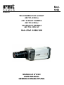
1
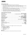
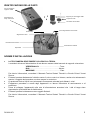
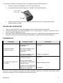
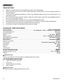
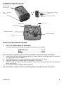
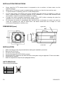
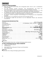
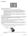
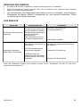
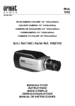
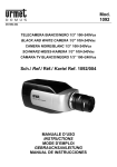
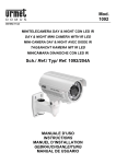
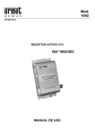
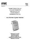
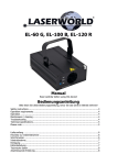
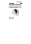
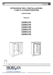
Mod.
1092
DS1092-071
TELECAMERA DAY & NIGHT
420 TVL 230Vca
DAY & NIGHT CAMERA
420 TVL 230Vac
TAG&NACHT KAMERA
420 TVL 230V AC
Sch./Ref. 1092/120
MANUALE D’USO
USER MANUAL
GEBRAUCHSANLEITUNG
ITALIANO
PRECAUZIONI D’USO
•
•
•
•
•
•
•
•
Assicurarsi dell’integrità dell’apparecchio dopo averlo tolto dall’imballo.
Prima di effettuare qualsiasi operazione di pulizia o di manutenzione disinserire l’apparecchio dalla
rete di alimentazione elettrica. Non usare prodotti spray per la pulizia dell’apparecchio.
Controllare che la temperatura d’esercizio sia nei limiti indicati e che l’ambiente non sia
particolarmente umido.
Non toccare la superficie del sensore della telecamera. Se questo dovesse essere accidentalmente
toccato, dovrà essere pulito con un panno morbido inumidito con alcool.
Evitare di puntare la telecamera contro il sole per non danneggiare il CCD.
In caso di guasto e/o cattivo funzionamento togliere l’alimentazione tramite l’interruttore generale.
Il dispositivo deve essere aperto soltanto da personale tecnico qualificato.
Per le riparazioni rivolgersi solo ad un centro di assistenza tecnica autorizzato.
CARATTERISTICHE TECNICHE
Tipo di sensore: .............................................................................................................. CCD 1/3”Super HAD
Sistema di scansione:......................................................... 2:1 interlacciato PAL - V:50 Hz – H:15.625 KHz
Risoluzione orizzontale:..................................................................................................................... 420 linee
Sincronizzazione: ..................................................................................................................................Interna
Compatibilità ottica: .......................................................................................................... DC Drive / Manuale
Controllo shutter: ............................................................................................1/50 ~ 1/100.000 sec (ON/OFF)
Compensazione controluce: ........................................................................................ Selezionabile ON/OFF
Bilanciamento del bianco: ........................................................................................................ AUTOMATICO
Controllo del guadagno: .............................................................................................. Selezionabile ON/OFF
Sensibilità minima:................................................................................................................................ 0.5 Lux
Uscita video: ..............................................................................................Uscita composita 1 Vpp, 75 Ohm
Attacco obiettivi: ............................................................................................................................... Tipo”CS”
Rapporto S/R:..........................................................................................................................................48 dB
Alimentazione: ............................................................................................................................. 100÷240 Vca
Consumo: .................................................................................................................................................... 3W
Temperatura di utilizzo: ...................................................................................................................... -10÷50°c
Temperatura d’immagazzinamento: ................................................................................................... -20÷60°c
Dimensioni (L x P x H):......................................................................................................... 117 x 71 x 66mm
Peso: ...................................................................................................................................................... 438 gr
eNota Bene
Le caratteristiche tecniche possono essere soggette a variazione senza alcun preavviso.
ACCESSORI A CORREDO
•
•
•
•
Connettore AUTO-IRIS a 4 poli.
Coperchio CCD.
Piastrina per fissaggio staffa.
Manuale d’uso.
eNota Bene
La composizione degli accessori a corredo può essere variata senza alcun preavviso.
2
DS1092-071
IDENTIFICAZIONE DELLE PARTI
Fori di montaggio
supporto staffa
Supporto per montaggio staffa
Regolazione di
easy back-focus
Coperchio CCD
Connettore AUTO-IRIS
Led di segnalazione accensione
Uscita video
Regolazione Level
Connettore AUTO-IRIS
Alimentazione 230Vca
Dip Switch
NORME D’INSTALLAZIONE
•
LA TELECAMERA DEVE ESSERE COLLEGATA A TERRA.
I conduttori del cavo d’alimentazione di rete devono essere cablati secondo la seguenti colorazione:
VERDE/GIALLO: ........................................... Terra
BLU: .............................................................Neutro
MARRONE:.....................................................Fase
•
•
•
•
•
Per ulteriori informazioni, consultare il “Manuale Tecnico Sistemi Televisivi a Circuito Chiuso” Urmet
Domus.
Evitare di puntare direttamente l’obiettivo contro il sole o contro luci intense, anche se la telecamera è
spenta; il soggetto da riprendere non deve essere in controluce.
La presenza di alcuni tipi di luce (ad esempio fluorescente colorata) può sfalsare i colori.
E’opportuno prevedere a monte degli apparecchi un idoneo interruttore di sezionamento e di
protezione.
Prima di collegare l’apparecchio alla rete di alimentazione accertarsi che i dati di targa siano
rispondenti a quelli della rete di distribuzione.
Evitare di puntare la telecamera verso oggetti riflettenti.
Per ulteriori informazioni, consultare il “Manuale Tecnico Sistemi Televisivi a Circuito Chiuso” Urmet
Domus.
DS1092-071
3
PRECAUZIONI PER L’INSTALLAZIONE
•
Non installare la telecamera in ambienti esposti alla pioggia o all'umidità. In questi casi utilizzare le
apposite custodie.
Quando si usa la telecamera in ambienti in cui l’illuminazione varia, è necessario prevedere l’uso di
un obiettivo con AUTO-IRIS.
Per prevenire il surriscaldamento del dispositivo, collocarlo in una posizione ben aerata.
Per lo stesso motivo non deve essere installato vicino a fonti di calore come radiatori o condotti d’aria
calda o in posizioni dove sia esposto direttamente all’irradiazione solare così come non deve essere
installato in locali soggetti a eccessiva polvere, vibrazioni meccaniche o urti.
Tenere in considerazione la temperatura di funzionamento dell’unità (-10°C÷+50°C) prima di
scegliere il luogo per l’installazione. Non installare l’unità sopra un’altra apparecchiatura che emani
calore.
Non mettere in funzione il dispositivo immediatamente dopo il trasporto da un luogo freddo ad un
luogo caldo e viceversa. Attendere mediamente tre ore: questo intervallo di tempo è necessario al
dispositivo per adattarsi al nuovo ambiente (temperatura,umidità,ecc.).
•
•
•
•
•
DIMENSIONI (mm)
Lato superiore
Lato inferiore
INSTALLAZIONE
1.
2.
3.
4.
5.
6.
7.
Prima d’iniziare l’installazione, assicurarsi che tutte le unità da collegare non siano alimentate.
Togliere il coperchio di protezione del CCD.
Montare l’obiettivo sulla telecamera.
Collegare il cavo al connettore AUTO-IRIS .
Collegare l’uscita video all’utilizzatore previsto utilizzando un cavo coassiale da 75 Ohm omologato.
Alimentare la telecamera.
Effettuare le regolazioni necessarie (vedere il paragrafo successivo).
CONNETTORE AUTO-IRIS
Definizione PIN connettore Auto-Iris
PIN
1
2
3
4
4
DC
DAMP (-)
DAMP (+)
DRIVER (+)
DRIVER (-)
1
3
2
4
DS1092-071
PROCEDURA DI MESSA A FUOCO PER OTTICHE AUTO-IRIS
1.
2.
3.
4.
5.
6.
Posizionare il selettore ELC/ALC del dip-switch sulla posizione ELC (utilizzando lenti tipo Dc driver).
Puntare la telecamera sul campo da riprendere assicurandosi che la luce sia sufficiente per la
ripresa; ruotare il trimmer LEVEL sino ad ottenere un’immagine totalmente bianca. Questa procedura
provoca la massima apertura del diaframma dell’obbiettivo con il minimo campo focale in modo da
ottimizzare la messa a fuoco del punto desiderato.
Posizionare il dip-switch sulla posizione ELC per ottenere l’immagine nuovamente visibile e
correttamente contrastata.
Effettuare la regolazione del fuoco se si usa una lente a ottica fissa. Se la lente è di tipo varifocal
eseguire la regolazione di zoom e fuoco.
Se le immagini non risultassero perfettamente a fuoco, agire sulla registrazione di Easy Back Focus;
al termine della registrazione avvitare il perno di registrazione per non perdere la regolazione
eseguita.
Riposizionare il dip-switch sulla posizione ALC per ottenere nuovamente la visione delle immagini
bianche o sature di bianco; regolare il trimmer LEVEL sino a ottenere la corretta luminosità dell’
immagine
USO DI COMANDI E PREDISPOSIZIONI
Led di segnalazione accensione
Uscita video
Regolazione Level
Connettore AUTO-IRIS
Alimentazione 230Vca
Dip Switch
Regolazione di
easy back-focus
DS1092-071
5
USO DEI DIP SWITCH
Controllo automatico dell’esposizione (ELC-ALC)
Per mezzo del commutatore ELC/ALC è possibile selezionare 2 tipi di obiettivi:
•
Obiettivi DC driver (senza amplificatore): posizionare il commutatore sulla posizione ALC. La
velocità dell’otturatore elettronico viene automaticamente variata in funzione delle condizioni di
illuminazione ambientale; nel caso che non si ottenga un’immagine chiara e pulita si può agire
sulle regolazioni di LEVEL della telecamera. La velocità dell’otturatore elettronico rimane
costante (1/50 di secondo).
•
Obiettivi MANUALI: posizionare il commutatore sulla posizione ELC. La velocità dell’otturatore
elettronico varia automaticamente in funzione della luce (da 1/50 di secondo a 1/100.000 di
secondo).
Compensazione controluce (BLC-OFF)
Un soggetto inquadrato con una forte luce proveniente da dietro solitamente appare scuro e poco visibile
rispetto al resto dell’immagine. Per ovviare a questo inconveniente ed ottenere una buona compensazione,
posizionare l’interruttore del dip-switch sulla posizione BLC.
Modalità anti-sfarfallio (FLC-OFF)
Uno sfarfallio sullo schermo può essere causato da una fonte luminosa fluorescente a 50 HZ. Per ridurre il
fenomeno posizionare l’interruttore del dip-switch sulla posizione FLC.
Controllo automatico del guadagno (AGC-OFF)
Selezionando il dip-switch nella posizione AGC si aumenta l’amplificazione del segnale in condizioni di
bassa luminosità ambientale permettendo di continuare ad avere una immagine più luminosa anche con
bassa illuminazione.
6
DS1092-071
La telecamera 1092/120 è predisposta per il montaggio mediante staffa di supporto.
•
Fissare il supporto di fissaggio con le tre viti alla telecamera.
•
E’ possibile posizionare tale supporto su entrambi i lati della telecamera.
Fori di montaggio
supporto staffa
•
Fissare la base sul lato inferiore per il posizionamento a parete o sul lato superiore per il
posizionamento a soffitto.
PULIZIA DEL DISPOSITIVO
•
•
•
Usare un panno asciutto e strofinare leggermente per eliminare polvere o sporcizia.
Nel caso la sporcizia non fosse eliminabile con un panno asciutto, compiere l’operazione con un
panno inumidito di detergente neutro.
Non usare liquidi volatili come benzina, alcool, solventi, ecc. o panni trattati chimicamente per pulire il
dispositivo al fine di evitare deformazioni, deterioramenti o graffi nella finitura della superficie.
DIAGNOSTICA
PROBLEMI
POSSIBILI CAUSE
La tensione di rete non è
compatibile con la
minicamera
Non appare nessuna
immagine a monitor
Verificare
Non è stato collegato il cavo
di alimentazione della
minicamera
Non è stato collegato il cavo
video della minicamera
La lente esterna della
minicamera è sporca
Le immagini sul monitor non
sono nitide
SOLUZIONI
Non sono state regolate
correttamente le impostazioni
di messa a fuoco
Eseguire i collegamenti
Verificare
Regolare Messa a Fuoco
Il monitor non è correttamente
regolato nelle impostazioni di
Correggere
Contrasto e Luminosità
Nel caso in cui il problema riscontrato non fosse risolvibile seguendo le indicazioni della tabella sopra
riportata, contattare un centro di assistenza tecnica autorizzato.
DS1092-071
7
ENGLISH
PRECAUTIONS
•
•
•
•
•
•
•
•
Make sure that the device is intact after removing it from the package.
Disconnect the device from the mains before cleaning or maintenance. Do not use spray products to
clean the device.
Check that the working temperature is within the indicated range and that the environment is not
particularly humid.
Do not touch the camera sensor surface. Clean the surface with a soft cloth and methylated spirit in
the event of accidental contact.
Do not point the camera towards the sun to prevent damaging the CCD.
Disconnect power by means of the circuit breaker in the event of a failure and/or bad operation.
The device can only be opened by qualified technical personnel.
Exclusively contact an authorised service centre for repairs.
TECHNICAL SPECIFICATIONS
Type of sensor:............................................................................................................... CCD 1/3”Super HAD
Scanning system: .............................................................. 2:1 interlaced - CCIR - V: 50 Hz - H: 15.625 kHz
Horizontal resolution:........................................................................................................................ 420 lines
Synchronisation: ...................................................................................................................................Internal
Optics: ................................................................................................................................ DC Drive / Manual
Shutter control: ...............................................................................................1/50 ~ 1/100.000 sec (ON/OFF)
Back-lighting compensation:............................................................................................. Selectable ON/OFF
White balancing: ..................................................................................................................................... AUTO
Gain control: ..................................................................................................................... Selectable ON/OFF
Minimum sensitivity: ............................................................................................................................. 0.5 Lux
Video output: .............................................................................................Composite output 1Vpp, 75 Ohm
Lens fitting: ..................................................................................................................................... ”CS” Type
S/R ratio:..................................................................................................................................................48 dB
Power: .................................................................................................................................................. 230Vac
Consumption: .............................................................................................................................................. 3W
Working temperature range:............................................................................................................... -10÷50°c
Storage temperature range: ............................................................................................................... -20÷60°c
Dimensions (W x D x H): ...................................................................................................... 117 x 71 x 66mm
Weight: ................................................................................................................................................... 438 gr
eImportant note:
Product specifications may be subject to change without prior notice.
ACCESSORIES PROVIDED
•
•
•
•
4 pole AUTO-IRIS connector.
CCD cover.
Stand for bracket mounting.
User manual.
eImportant note:
Accessories may be changed without prior notice.
8
DS1092-071
ELEMENTS IDENTIFICATION
Mounting holes for
bracket support
Stand for bracket mounting
Easy
back-focus
adjustment
CCD cover
AUTO-IRIS connector
Power-on led
Video output
Level adjustment
AUTO-IRIS connector
230Vac power supply
Dip Switch
INSTALLATION SPECIFICATIONS
•
THE CCTV CAMERA MUST BE GROUNDED.
The mains cables must be wired according to the following colour coding:
GREEN/YELLOW: ......................................Ground
BLUE:.......................................................... Neutral
BROWN: ...................................................... Phase
See Urmet Domus “Closed circuit TV technical installation manual” for further information.
•
Avoid pointing the lens directly towards the sun or intense sources of light also when the camera is
off. The subject must not be backlit.
•
Some lighting systems (e.g. coloured fluorescent lights) may false the colours.
•
Arrange a suitable circuit breaker and fuse upstream of the devices.
•
Make sure that the rating plate data correspond to the power specifications before connecting the
device to the mains.
•
Do not point the camera towards reflecting objects.
See Urmet Domus “Closed circuit TV technical installation manual” for further information.
DS1092-071
9
INSTALLATION PRECAUTIONS
•
Never install the CCTV camera where it is exposed to rain or moisture. In these cases, use the
specific housings.
When the CCTV camera is used in variable lighting conditions, an Auto-Iris lens must be used.
To prevent device overheating, place it in a well aired position.
For the same reason, the device must not be installed near heat sources as radiators or warm air
ducts, in places where it is directly exposed to sun irradiation or in rooms with excessive dust
accumulation, subject to mechanical vibrations or impacts.
Consider the device operating temperature range (-10°C÷+50°C) before choosing the place for
installation. Do not install the unit over another heating device.
Do not power the device on immediately after moving it from a cold place to a warm one and vice
versa. As a general rule, wait for three hours: the device needs this time to adapt to a new
environment (temperature, humidity, etc.).
•
•
•
•
•
DIMENSIONS (mm)
Upper side
Lower side
INSTALLATION
1
2
3
4
5
6
7
Make sure that no units are powered before starting the installation procedure.
Remove the CCD cover.
Fit the lens on the camera.
Connect the wire to the AUTO-IRIS connector .
Connect the CCTV camera to the other devices of the system using an approved 75 ohm coax cable.
Power the mini camera.
Make the adjustments required (see paragraph below)
AUTO-IRIS PLUG
Auto-Iris plug PIN definition
PIN
1
2
3
4
10
DC
DAMP (-)
DAMP (+)
DRIVER (+)
DRIVER (-)
1
3
2
4
DS1092-071
FOCUSING PROCEDURE FOR AUTO-IRIS LENSES
1.
2.
3.
4.
5.
6.
Set the dip-switch ELC/ALC selector to ELC position (using Dc driver lenses).
Point the camera at the field to be shot and make sure light is sufficient for shooting; rotate the
trimmer LEVEL until the image is totally white. This procedure causes the maximum f-stop aperture,
with the minimum focus field, in order to optimize the focusing of the desired point.
Set the dip-switch to ELC position to make the image visible again and with a right contrast.
Perform focus adjustment if a fixed lens is used. If the lens is varifocal, adjust zoom and focus.
If images focus is not perfect, adjust Easy Back Focus; after adjustment, screw the adjustment pin in
order not to lose the adjustment just performed.
Set again the dip-switch to ALC position to obtain again white or white saturated images; adjust the
trimmer LEVEL until image brightness is correct.
USING COMMANDS AND PRESETTINGS
Power-on led
Video output
Level adjustment
AUTO-IRIS connector
230Vac power supply
Dip Switch
Easy
back-focus
adjustment
DS1092-071
11
DIP SWITCHES USE
Exposure automatic control (ELC-ALC)
2 kinds of lenses can be chosen by means of ELC/ALC switch:
•
DC driver lenses (without amplifier); put the switch on position ALC. The electronic shutter
speed is automatically changed according to environment lighting conditions; if the obtained
image is not clear and sharp it is possible to change camera LEVEL adjustments. The electronic
shutter speed is not affected (1/50 second).
•
MANUAL lenses: put the switch on ELC position. The electronic shutter speed automatically
changes according to light (from 1/150 second to 1/100.000 second).
Backlight compensation (BLC-OFF)
An object with a strong light in the background usually appears dark and not so visible if compared with the
rest of image. To solve this problem and obtain a good compensation, put the dip-switch on BLC position.
The BLC function allows to solve this problem and obtain a good compensation.
Anti-flicker mode (FLC-OFF)
Flicker on the screen can be caused by a 50 HZ fluorescent light source. To reduce this effect, put the dipswitch on FLC position.
Gain automatic control (AGC-OFF)
Put the dip-switch in AGC position to increase the signal amplification under poor light environmental
conditions, allowing to have a brighter image also under poor light conditions.
The camera 1092/120 can be installed using a support bracket.
•
Fasten the fixing support to the camera with the three screws.
•
This support can be installed on both camera sides.
Bracket
support
mounting holes
•
12
Fix the base on the lower side for wall mounting or on the upper side for ceiling mounting.
DS1092-071
CLEANING THE DEVICE
•
•
•
Rub delicately with a dry cloth to remove dust and dirt.
Dip the cloth in neutral detergent if dirt cannot be eliminated with a dry cloth alone.
Do not use volatile liquids (such as petrol, alcohol, solvents, etc.) or chemically treated clothes to
clean the device to prevent deformation, deterioration or scratches to the paint finish.
TROUBLESHOOTING
PROBLEMS
No image displayed on the
screen
POSSIBLE CAUSES
The mains voltage is not
Check
compatible with the
minicamera.
The minicamera power supply
cable has not been
connected.
The minicamera video cable
has not been connected.
Make the connections
The minicamera external lens
is dirty.
Displayed images are not
sharp enough.
SOLUTIONS
Focus settings are not
correctly adjusted.
Monitor contrast and
brightness settings are not
correctly adjusted.
Check
Adjust focus
Modify
If the problem can not be solved following the instructions in the table above, contact an authorized
technical assistance.
DS1092-071
13
DEUTSCH
VORSICHTSMASSNAHMEN
•
•
•
•
•
•
•
Nach dem Auspacken des Gerätes muss sichergestellt werden, dass es sich in einwandfreiem
Zustand befindet.
Vor dem Ausführen jeglicher Reinigungs- oder Wartungsarbeiten, das Gerät vom
Stromversorgungsnetz trennen. Für die Reinigung des Geräts keine Sprays verwenden.
Wenn extern installiert, ist die Positionierung in einer geschützten Umgebung vorzuziehen, d.h., nicht
in direktem Kontakt mit großen Witterungseinflüssen (Regenfälle oder erhöhte Temperaturen).
Die Oberfläche des Sensors der Kamera nicht berühren. Sollte dieser versehentlich berührt werden,
muss er mit einem weichen, mit Alkohol befeuchteten Tuch gereinigt werden.
Bei Defekten und/oder mangelnder Funktionstüchtigkeit, die Versorgung über den Hauptschalter
abschalten.
Das Gerät darf nur von qualifiziertem technischem Personal geöffnet werden.
Für Reparaturen wenden Sie sich bitte nur an ein autorisiertes Zentrum des technischen
Kundendiensts.
TECHNISCHE EIGENSCHAFTEN
Sensorart: ....................................................................................................................... CCD 1/3”Super HAD
Scannersystem:.............................................................. 2:1 Verflochten - CCIR - V: 50 Hz - H: 15.625 kHz
Horizontale Auflösung: ................................................................................................................... 420 Linien
Synchronisierung:....................................................................................................................................Intern
Optik: ................................................................................................................................. DC Drive / Manuell
Steuerung Shutter: ....................................................................................... 1/50 ~ 1/100.000 Sek. (ON/OFF)
Gegenlicht-Kompensation: .............................................................................................Auswählbar ON/OFF
Weißabgleich:......................................................................................................................................... AUTO
Steuerung der Verstärkung: ...........................................................................................Auswählbar ON/OFF
Mindest-Beleuchtungsstärke: ............................................................................................................... 0.5 Lux
Videoausgang:........................................................................... Mehrteiliger Videoausgang 1Vpp, 75 Ohm
Objektivbefestigung: ....................................................................................................................... ”CS” Type
Verhältnis S/R:.........................................................................................................................................48 dB
Versorgung: ........................................................................................................................................ 230V AC
Verbrauch: ................................................................................................................................................... 3W
Betriebstemperatur: .......................................................................................................................... -10÷50° C
Lagertemperatur: .............................................................................................................................. -20÷60° C
Abmessungen (B x L x T): .................................................................................................... 117 x 71 x 66mm
Gewicht:................................................................................................................................................... 438 g
eBeachten:
Produkteigenschaften können ohne vorherige Ankündigung geändert werden.
IN DER LIEFERUNG ENTHALTENS ZUBEHÖR
•
•
•
•
4 poliger AUTO-IRIS Verbinder.
CCD Abdeckung
Halterungsfuß mit drei Schrauben für Wand- oder Deckenhalter.
Gebrauchsanleitung
eBeachten:
Zubehör kann ohne vorherige Ankündigung geändert werden.
14
DS1092-071
IDENTIFIZIERUNG DER TEILE
Befestigung
des
Halterungsfußes
Fuß für Befestigungshalter
Einfache
Schärfeeinstellung
CCD Abdeckung
AUTO-IRIS Verbinder
LED
Videoausgang
LEVEL Einstellung
AUTO-IRIS Anschluss
230V AC Versorgung
Dip Switch
INSTALLATION
•
DIE CCTV KAMERA MUSS GEERDET WERDEN.
Die Versorgungsleitung muss wie folgt angeschlossen werden:
GRÜN-GELB:.................................................. Erde
BLAU: .......................................................Nullleiter
BRAUN: ....................................................... Phase
•
•
•
•
•
Vermeiden Sie es, das Objektiv direkt gegen die Sonne oder intensive Lichteinstrahlung zu richten,
auch bei ausgeschalteter Kamera. Der aufzunehmende Gegenstand darf sich nicht im Gegenlicht
befinden.
Einige Lichtarten (z.B. fluoreszierendes farbiges Licht) können die Farben verfälschen.
Es ist von Vorteil dem Gerät einen geeigneten Trenn – und Schutzschalter vorzuschalten.
Bevor das Gerät an das Versorgungsnetz angeschlossen wird, ist sicherzustellen, dass die
Kenndaten denen des Verteilernetzes entsprechen.
Die Kamera nicht auf reflektierende Objekte ausrichten.
DS1092-071
15
INSTALLATIONSBESTIMMUNGEN
•
Die Kamera nicht in Regen oder Feuchtigkeit ausgesetzten Umgebungen installieren. In diesen
Fällen die dafür vorgesehenen Gehäuse verwenden.
Wird die Kamera in Umgebungen mit wechselndem Lichteinfall eingesetzt, muss die Verwendung mit
AUTO-IRIS Objektiven vorgesehen werden.
Zum Schutz der Überhitzung bitte das Gerät in gut klimatisierten Bereichen montieren.
Das Gerät nicht in Umgebungen verwenden, in denen Rauch, Dampf, Staub oder starke Vibrationen
vorhanden sind.
Achten Sie auf die Betriebstemperatur (-10°C÷+50°C) des Gerätes, bevor Sie den geeigneten Ort der
Installation auswählen. Installieren Sie das Gerät daher nicht in der Nähe von Wärmequellen.
Gerät nicht unmittelbar nach dem Transport von einem kühlen an einen warmen Ort oder umgekehrt
in Betrieb nehmen. Im Durchschnitt sind drei Stunden abzuwarten: dieser Zeitraum ist erforderlich,
damit das Gerät sich an die neue Umgebung anpassen kann (Temperatur, Feuchtigkeit, etc.).
•
•
•
•
•
ABESSUNGEN (mm)
Oben
Unten
INSTALLATION
1
2
3
4
5
6
7
Vor der Installation sicherstellen, dass alle anzuschließenden Einheiten von der Versorgung
getrennt sind.
Entfernen der CCD Abdeckung.
Das Objektiv auf die Kamera montieren.
Wenn vorhanden, den AUTO-IRIS Stecker des Objektivs mit der Kamera zu verbinden.
Die Kamera an die anderen Vorrichtungen der Anlage anschließen, indem Sie ein geeignetes
Koaxialkabel (z. B: RG59) mit 75 Ohm verwenden.
Schalten Sie die Versorgungsspannung ein.
Die notwendigen Einstellungen durchführen (siehe nachfolgender Abschnitt)
AUTO-IRIS VERBINDER
Definition Pin AUTO-IRIS Verbinder
PIN
1
2
3
4
16
DC
DAMP (-)
DAMP (+)
DRIVER (+)
DRIVER (-)
1
3
2
4
DS1092-071
VORGANG DER SCHARFEINSTELLUNG MIT AUTO-IRIS OPTIKEN
1.
2.
3.
4.
5.
6.
Den DIP-Switch ELC/ALC auf ELC positionieren (bei Einsatz von DC gesteuerten Objektiven).
Ausrichtung der Kamera auf den gewünschten Bildausschnitt und dafür sorgen dass gute
Lichtverhältnisse im gewünschten Bildausschnitt vorhanden sind; den LEVEL-Regler drehen, bis
ein weißes Bild erscheint. Diese Prozedur bewirkt bei maximaler Öffnung der Blende mit einem
minimalen Schärfefeld, eine optimale Einstellung des gewünschten Bildausschnitts.
Den Dip-Switch auf die Position ELC stellen, um das Videobild wieder mit dem richtigen Kontrast
anzuzeigen.
Bei Objektiven mit fester Brennweite die Schärfe anpassen. Werden varifokale Objektive
eingesetzt, den Zoom und die Schärfe regulieren .
Ist die Bildschärfe nicht ausreichend kann über die einfache Schärfeeinstellung an der Seite der
Kamera weiter reguliert werden; nach der Justierung sollte die Feststellschraube wieder
festgeschraubt werden.
Den Dip-Switch auf die Position ALC stellen um weiße oder weiß gesättigte Videobilder zu
erhalten; den LEVEL-Regler so einstellen, bis die korrekte Bildhelligkeit erreicht ist.
VERWENDUNG DER STEUERUNGEN UND VOREINSTELLUNGEN
LED
Videoausgang
LEVEL Einstellung
AUTO-IRIS Anschluss
230V AC Versorgung
Dip Switch
Einfache
Schärfeeinstellung
DS1092-071
17
DIP SWITCHE
Steuerung der AUTO-IRIS (ELC-ALC)
Mittels des Dip-Switches ELC/ALC ist es möglich, zwei Objektivtypen auszuwählen:
•
DC gesteuerte Objektive (ohne Verstärker); den Schalter auf die Position ALC Stellen. Die
Geschwindigkeit des elektronischen Shutters passt sich automatisch den gegebenen
Lichtverhältnissen an; sollte kein klares und sauberes Bild erzielt werden können die LEVELEinstellungen der Kamera verwendet werden. Der elektronische Shutter wird davon nicht
beeinträchtigt (1/50 Sekunden).
•
Manuelle Objektive: den Schalter auf die Position. Die Geschwindigkeit des elektronischen
Shutters passt sich automatisch den gegebenen Lichtverhältnissen an (von 1/150 Sekunde bis
1/100.000 Sekunde).
Gegenlicht-Kompensation (BLC-OFF)
Ein ausgewählter Gegenstand mit starkem, von hinten kommendem Licht erscheint normalerweise dunkel
und im Vergleich zum Rest des Bildes schlecht sichtbar. Um diesem Problem abzuhelfen und einen guten
Ausgleich zu erzielen, den Schalter BLC der Dip Switche auf Position BLC stellen.
Anti-flicker mode (FLC-OFF)
Ein Flackern auf dem Bildschirm kann durch floureszierendes Licht bei 50 Hz verursacht werden. Um
dieses Phänomen zu verringern, den Schalter FLC der Dip Switche auf die Position FLC stellen.
Automatische Steuerung der Verstärkung (AGC-OFF)
Die Verwendung der automatischen Verstärkung (Schalter AGC der Dip-Switche auf Position AGC stellen)
gestattet die Erhaltung eines klaren Bildes auch unter mittleren bis schlechten Lichtbedingungen der
Umgebung.
Die Kamera 1092/120 kann mit einem Halterungsfuß an Wand- oder Deckenhalterungen montiert werden.
•
Befestigen des Halterungsfußes mit den drei im Lieferumfang enthaltenen Schrauben.
•
Der Halterungsfuß kann beidseitig montiert werden.
Befestigung
des
Halterungsfußes
•
18
Montieren der Kamera mit der Unterseite bei einem Wandhalter und an der Oberseite bei einem
Deckenhalter.
DS1092-071
REINIGUNG DES GERÄTES
•
•
Um Staub und Schmutz zu entfernen, Gerät mit einem trockenen Tuch abreiben.
Sollte der Schmutz mit einem trockenen Tuch nicht zu entfernen sein, Gerät mit einem feuchten
Lappen und Neutralreiniger abwischen.
•
Um Verformungen, Beschädigungen oder Kratzer im Lack zu verhindern, keine flüchtigen
Flüssigkeiten wie Benzin, Alkohol, Lösungsmittel etc. oder chemisch behandelte Tücher
zur Reinigung des Geräts verwenden.
FEHLERSUCHE
PROBLEM
Es wird kein Bild am Monitor
angezeigt
Angezeigte Videobilder
haben keine Tiefenschärfe.
FEHLERURSACHE
Die Spannungsversorgung ist
nicht kompatibel zur Kamera.
Die Spannungsversorgung ist
nicht an der Kamera
angeschlossen.
Das Videokabel ist nicht an
die Kamera angeschlossen.
LÖSUNGEN
Überprüfen und Messen der
Versorgungsspannung
Verbindungen herstellen
Das Objekt an der Kamera ist
verunreinigt.
Überpüfen und gegebenenfalls Reinigen
des Objektivs
Die Fokus-Einstellung sind
nicht korrekt eingestellt.
Einstellen der Fokussierung
Die Einstellungen der
Helligkeit und des Kontrastes
sind am Monitor nicht richtig
eingestellt.
Anpassen des Monitorbildes
Sollte das anstehende Problem nicht behoben werden können, kontaktieren Sie bitte zur Hilfe einen
autorisierten Kundenservice.
DS1092-071
19
DS1092-071
Prodotto in Cina su specifica URMET Domus
Made in China to URMET Domus specification
FILIALI
20151 MILANO – V.Gallarate 218
Tel. 02.380.111.75 - Fax 02.380.111.80
00043 CIAMPINO (ROMA) V.L.Einaudi 17/19A
Tel. 06.791.07.30 - Fax 06.791.48.97
80013 CASALNUOVO (NA) V.Nazionale delle Puglie 3
Tel. 081.193.661.20 - Fax 081.193.661.04
30030 VIGONOVO (VE) – V.del Lavoro 71
Tel. 049.738.63.00 r.a. - Fax 049.738.63.11
66020 S.GIOVANNI TEATINO (CH) – V.Nenni 17
loc. Sambuceto Tel. 085.44.64.851
Tel. 085.44.64.033 - Fax 085.44.61.862
SEDE
20
URMET DOMUS S.p.A.
10154 TORINO (ITALY)
VIA BOLOGNA 188/C
Telef.
+39 011.24.00.000 (RIC.AUT.)
Fax
+39 011.24.00.300 - 323
Area Tecnica
Servizio Clienti +39 011.23.39.810
http://www.urmetdomus.com
e-mail: [email protected]
DS1092-071