1
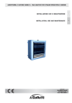
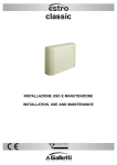
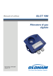
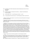
MANUALE TECNICO e di INSTALLAZIONE destratificatori d'aria
Air destratifiers TECHNICAL and INSTALLATION MANUAL
I
GB
DST
INDICE
INDEX
1
GENERALITÀ ...................................................................... 3
1
MAIN FEATURES ................................................................. 3
2
DESCRIZIONE DELL'UNITÀ ............................................... 3
2
UNIT DESCRIPTION ............................................................. 3
3
CARATTERISTICHE COSTRUTTIVE ................................. 4
3
CONSTRUCTIVE FEATURES .............................................. 4
4
CARATTERISTICHE TECNICHE NOMINALI ...................... 7
4
RATED TECHNICAL DATA .................................................. 4
5
DIMENSIONI DI INGOMBRO ............................................... 5
5
OVERALL DIMENSIONS ...................................................... 5
6
CRITERI DI SCELTA ............................................................ 6
6
HOW TO CHOOSE THE DESTRATIFIER .............................. 6
7
PRIMA DI INIZIARE L’INSTALLAZIONE ............................ 6
7
BEFORE STARTING INSTALLATION .................................. 6
8
UTILIZZO PREVISTO E LIMITI DI FUNZIONAMENTO ...... 6
8
INTENDED USE AND OPERATING LIMITS .......................... 6
9
INSTALLAZIONE ................................................................. 6
9
INSTALLATION .................................................................... 6
10
USO E MANUTENZIONE ..................................................... 7
10
MAINTENANCE .................................................................... 7
11
RICERCA DEI GUASTI ........................................................ 7
11
TROUBLESHOOTING ........................................................... 7
DICHIARAZIONE DI CONFORMITÀ
La Galletti S.p.A. con sede in via Romagnoli 12/a, 40010
Bentivoglio (BO) – Italia - dichiara, sotto la propria
responsabilità, che i destratificatori serie DST, apparecchi
di ventilazione, sono conformi a quanto prescritto dalle
Direttive CEE 73/23, 89/392, 91/368, 93/44, 93/68, 89/336,
83/97 e successive modifiche.
DECLARATION OF CONFORMITY
Galletti S.p.A. whose main office is located at 12/a via
Romagnoli, 40010 Bentivoglio (BO) - Italy, hereby declares,
under its own responsibility, that the destratifiers belonging
to the DST series, conform to the specifications of EEC
Directives 73/23, 89/392, 91/368, /93/44, 93/68, 89/336,
83/97 and subsequent modifications.
Bologna li, 30/05/2003
Bologna 30/05/2003
Luigi Galletti
Presidente
Luigi Galletti
President
I dati tecnici e dimensionali riportati nella presente documentazione
possono subire variazioni orientate al miglioramento del prodotto.
AP66000373 - 00
The technical and dimensional data reported in this manual may be modified
in view of any product improvement.
2
DST
1
GENERALITÀ
1
Negli ambienti di lavoro riscaldati con sistemi ad aria calda, la
necessità di mantenere al livello di permanenza delle persone
una temperatura di circa 18°C comporta l’inconveniente di
addensare nella parte alta del locale una notevole quantità di
calore, che resta inutilizzato e destinato quindi a disperdersi
verso l’esterno.
MAIN FEATURES
In working environments heated with hot air systems the need to
keep the temperature at approximately 18°C, causes the air to
stratify at the top of the room, with much of the heat remaining
unused, which is destined to flow toward the atmosphere.
The DST destratifier eliminates this problem by generating a
vertical flow of air to reduce the difference between the temperature
at the floor and the temperature at the ceiling to about 3°C.
Il destratificatore DST elimina questo inconveniente,
generando un flusso d’aria verticale in grado di ridurre la differenza
fra la temperatura al pavimento e quella al soffitto a circa 3 °C.
In the hot season the DST destratifier may be used to obtain
a good ventilation.
Nei periodi caldi il destratificatore DST può essere utilizzato
per ottenere un’efficace ventilazione.
2
DESCRIZIONE DELL'UNITÀ
2
2
UNIT DESCRIPTION
11
5
3
10
1
4
7
6
8
9
(1)
(2)
(3)
(4)
(5 )
(6)
(7)
(8)
(9)
(10)
(11)
Mobile di copertura : pannello laterale
Mobile di copertura: pannello superiore/inferiore
Pannello posteriore/boccaglio ventilatore
Termostato di regolazione
Griglia antinfortunistica (ventola) supporto motore
Alette deflettrici orientabili
Scatola cablaggi
telesalvamotore
Angolare plastico di chiusura mobile (destro e sinistro)
Convogliatore aria
Staffe di fissaggio a parete/soffitto
(1)
(2)
(3)
(4)
(5)
(6)
(7)
(8)
(9)
(10)
(11)
3
Cabinet: side panel
Cabinet: upper/lower panel
Rear panel/fan compartment
Regulation thermostat
Safety grille (fan) supporting motor
Adjustable louvers
electrical box
Overload cut-out
Plastic corner trim on cabinet (left and right)
Conveyor duct
Wall/ceiling mounting brackets
AP66000373 - 00
DST
3
CARATTERISTICHE COSTRUTTIVE
3
CONSTRUCTIVE FEATURES
-
Mobile: in lamiera di acciaio preverniciata, completo di angolari
in ABS, è completo di alette deflettrici orientabili (a molla)
poste sulla mandata dell'aria per una distribuzione ottimale
nell'ambiente.
-
Cabinet: made of prepainted sheet metal complete with ABS
corner trim, is complete with adjustable aluminium louvers
(spring operated) placed on the air outlet which allow an
optimal distribution of the air.
-
Ventilatore assiale con pale a falce, bilanciate staticamente,
inserite in un apposito boccaglio che garantisce le prestazioni
aerauliche e riduce il rumore emesso.
-
Axial fan with statically balanced sickle blades housed in a
specially designed compartment that enhances ventilation
and reduces noise emission.
-
Griglia antinfortunistica in filo di acciaio elettrozincato:
sostiene il motore ed è fissata al mobile mediante supporti
antivibranti.
-
Safety grille made of electrogalvanised steel wire: it supports
the motor and is fixed to the cabinet by means of vibration
damping supports.
-
Motore: di serie con le seguenti caratteristiche
- a doppia velocità in esecuzione
- 400V trifase
- tipo stella triangolo
- cablato a 4 poli nel modello DST 14
- 6 poli nei successivi modelli.
- tropicalizzato
- dotato di protettore termico interno (klixon)
- con grado di protezione IP 55
- avvolgimenti in classe F
-
Motor: standard equipped with:
- two speeds
- power supply 400V - 3 - 50Hz
- delta-star type
- 4 poles operation for model DST 14
- 6 poles operation for all the models from 26 to 66
- tropicalized
- internal thermal protection (klixon)
- IP 55 grade of protection
- Class F windings
-
Telesalvamotore: a protezione del motore, a riarmo manuale.
-
Overload cut-out with manual reset for motor protection
-
Termostato di regolazione: collegato ad un teleruttore per
consentire l’avvio ed il blocco del destratificatore DST alla
temperatura prefissata.
-
Thermostat: connected to the overload cut-out to start and
stop the DST destratifier at the set temperature
-
Staffe di fissaggio: in acciaio zincato, per la sospensione
dell’apparecchio al soffitto.
Suspending brackets: made of stainless steel metal, for the
suspending the unit from the ceiling.
4
CARATTERISTICHE TECNICHE NOMINALI
Modello
Model
Velocità ventola
Fan speed
Portata aria
Air flow
Altezza min installazione
Min. installation height
Altezza max installazione
Max installation height
4
RATED TECHNICAL DATA
DST 14
DST 26
DST 36
DST 46
DST 56
DST 66
1400
900
900
900
900
900
1750
2750
3800
5000
6650
9500
m
3
3,5
4,5
5
7
6,5
m
5
5,5
7
7,5
9
10
m3/h
Alimentazione elettrica
Power supply
400-3-50
400-3-50
400-3-50
400-3-50
400-3-50
Potenza assorbita
Power input
V - ph - Hz 400-3-50
W
67
178
294
471
860
540
Corrente assorbita
Current Absorbed
A
0,21
0,4
0,58
0,85
1,37
1,18
Potenza sonora
Sound power
dB A
66
63
65
69
73
77
Pressione sonora
Sound pressure
dB A
44
41
43
47
51
51
Peso
Weight
kg
16
21
28
35
42
48
A-weighted sound pressure referred to a distance of 5 meters and
a directional factor of 2.
Lp Pressione sonora ponderata A, riferita ad una distanza di 5 m
e ad un fattore Q=2
AP66000373 - 00
4
DST
DIMENSIONI DI INGOMBRO
OVERALL DIMENSIONS
E
A
B
E
> 500
80
D
A
80
300
C
86
5
300
5
5
DST
A (mm)
B (mm)
C (mm)
D (mm)
E (mm)
14
460
300
350
300
500
26
560
400
450
400
500
36
660
500
550
500
525
46
760
600
650
600
515
56
860
700
750
700
535
66
960
800
850
800
535
AP66000373 - 00
DST
6
CRITERI DI SCELTA
6
HOW TO CHOOSE THE DESTRATIFIER
1) Set the units installation height in the environment.
2) Calculate the volume above the units and consider 5 volumes/
hour of air recirculation.
3) Select the unit with air flow rate equal or higher than the overall
volume to recirculate and the proper installation height.
ESEMPIO
Dimensioni dell'ambiente:
- larghezza 40 m
- lunghezza 100 m
- altezza 7,5 m
Altezza d installazione del destratificatore 6 m
il volume sovrastante l'apparecchio risulta di 3000 m3; ricircolare
almeno 3000 x 5 = 15000 m3/h.
La scelta più idonea sarà di n° 3 DST 46
EXAMPLE
dimensions of the building :
- width 40 m
- length 100 m
- height
7.5 m
Destratifier installation height 6 m
The volume above the destratifier is of 3000 sqm; recirculated air
flow should be at least 3000 x 5 = 15000 sqm/h.
The best choice is no. 3 DST 46.
1,5
1) Stabilire l'altezza di installazione degli apparecchi in ambiente.
2) Calcolare il volume sovrastante e prevedere un ricircolo di 5
volumi/ora.
3) Individuare l'apparecchio con portata aria uguale o superiore
al volume complessivo da ricircolare e l'altezza di installazione
idonea.
15
10
20
30
6
25
40
7
PRIMA DI INIZIARE L’INSTALLAZIONE
7
BEFORE STARTING INSTALLATION
Leggere attentamente questo manuale.
L’installazione e la manutenzione dell’apparecchio devono essere
effettuati esclusivamente da personale tecnico qualificato per
questo tipo di macchina, in conformità alle normative vigenti.
Al ricevimento dell’apparecchio controllarne lo stato, verificando
che non abbia subito danni dovuti al trasporto.
Carefully read this manual.
Installation and maintenance may be carried out solely by qualified
technicians specifically trained for this type of equipment, in
conformity with current regulations.
On receiving the equipment, check that it has not undergone any
damage during transport.
8
8
UTILIZZO PREVISTO E LIMITI DI FUNZIONAMENTO
INTENDED USE AND OPERATING LIMITS
La Galletti S.p.A. si ritiene sollevata da eventuali responsabilità
nei casi in cui:
- l’apparecchio sia installato da personale non qualificato,
- venga utilizzato impropriamente o in condizioni non ammesse
dal costruttore,
- non venga effettuata la manutenzione prevista dal presente
manuale;
- non siano stati utilizzati ricambi originali.
I limiti di funzionamento sono:
Temperatura aria aspirata -10°C / +40°C
Tensione di alimentazione +/- 10%
ogni altro uso è considerato improprio.
Galletti S.p.A. will not accept any liability for damage or injury
caused as a result of:
- installation by non-qualified personnel;
- improper use or use in conditions not allowed by the
manufacturer;
- failure to perform the maintenance prescribed in this manual;
- use of spare parts other than original factory parts.
The operating limits are:
Air inlet temperature: from -10°C to +40°C
Supply voltage: +/- 10%
usage outside the stated limits is to be considered improper.
9
9
INSTALLAZIONE
Nella scelta del luogo di installazione osservare i seguenti punti:
- non installare l’unità in ambienti con presenza di gas
infiammabili;
- non esporre l’unità direttamente a spruzzi di acqua;
- installare l’apparecchio su pareti o soffitti che ne reggano il
peso utilizzando accessori dedicati allo scopo e tasselli ad
espansione adeguati.
AP66000373 - 00
INSTALLATION
When choosing an installation site, you should observe the
following rules:
- do not install the unit in places where inflammable gases are
present;
- do not expose the unit directly to sprays of water;
- install the unit on walls or ceilings able to withstand its weight;
use accessories suited to the purpose and suitable screw
anchors.
6
DST
Conservare l’apparecchio nell’imballo fino al momento
dell’installazione in modo da evitare infiltrazioni di polvere al suo
interno.
Store the unit in its packing container until you are ready to install
it to prevent dust from infiltrating inside it.
Installation, maintenance and cleaning jobs may be carried out
only with the power supply disconnected.
Eseguire le operazioni di installazione, manutenzione e pulizia
in assenza di tensione.
Do not modify the indoor electrical connections and the
components of the unit.
Non modificare i cablaggi elettrici interni o altri particolari
dell’apparecchio.
Set the working temperature on the thermostat before lifting the
unit.
Using suitable lifting equipment (a forklift truck is recommended),
convey the unit to the installation site and rest it on the floor with
the fins facing down.
Use the suspending brackets on the back of the cabinet to support
the destratifier; before securing the unit to the ceiling ensure that
the supporting chains, the studs and the surface used are able
to support it.
Maintain adequate space around the destratifier to allow it to
operate correctly and to allow routine and reactive maintenance
to be performed.
When the installation has been finished, check the chains fastening
to the ceiling, check that the electrical wiring have been thightened,
open the deflecting baffles and connect the unit to power supply
in order to check its operation.
Make the electrical connections with the power supply
disconnected, in accordance with current safety regulations. All
the wiring must be done by qualified personnel.
Scrupulously follow the wiring diagram provided.
Check that the mains electricity supply is compatible with the
voltage shown on the unit rating plate.
It is mandatory to provide a circuit breaker (IL) with fuses (F),
positioned within a place easy to reach, to stop the unit in case
of emergency.
Line circuit-breaker (NOT SUPPLIED)
IL
Impostare sul termostato la temperatura di lavoro prima di
procedere al suo sollevamento.
Munirsi di un idoneo mezzo di sollevamento per portare il
destratificatore nella posizione di installazione appoggiandolo
dalla parte delle alette.
Per il sostegno del destratificatore utilizzare le 4 staffe presenti
nella parte posteriore della carcassa; prima di eseguire il fissaggio
a soffitto, verificare che le catene di sostegno, i tasselli e la
superficie utilizzate siano idonee a sostenere l’apparecchio.
Mantenere intorno all’apparecchio lo spazio necessario a
consentirne il corretto funzionamento e permettere di effettuare
operazioni di manutenzione ordinaria e straordinaria.
Ad installazione terminata controllare il fissaggio con le catene
al soffitto, controllare che i cablaggi elettrici siano ben saldi, aprire
le alette deflettrici e dare tensione all’apparecchio per verificarne
il funzionamento.
Effettuare i collegamenti elettrici in assenza di tensione, secondo
le normative di sicurezza vigenti.
Seguire scrupolosamente lo schema elettrico.
Verificare che la tensione di rete corrisponda a quella indicata
sulla targhetta dell’apparecchio. I collegamenti tratteggiati sono
a carico dell’installatore.
E’ obbligatorio prevedere per ciascuno apparecchio, un
interruttore di linea (IL) con fusibili (FL), posizionato in un luogo
facilmente accessibile per l’eventuale arresto di emergenza.
FL
ISM
K1
T
M
Interruttore di linea (NON FORNITO)
Fusibile di protezione (NON FORNITO)
Magnetotermico salvamotore
Teleruttore
Termostato
Motore
Protection fuse (NOT SUPPLIED)
Overload cut-out
remote control switch
Thermostat
Motor
FL
1
1 3 5 13
A1
K1
A2
2 4 6
K1
1
T
4
14
1 3 5
ISM
4
6
2 4 6
4
14
4
5
M1
7
W
2
V
1
3
W1
T
U
S
V1
400/3/50
R
U1
IL
FL
ISM
K1
T
M
11
M
3~
12
4
AP66000373 - 00
DST
10
10
USO E MANUTENZIONE
MAINTENANCE
E’ necessario prestare attenzione durante le operazioni di uso e
manutenzione: alcune parti metalliche possono provocare ferite;
dotarsi di guanti protettivi.
Per motivi di sicurezza, prima di utilizzare o di compiere qualsiasi
manutenzione o pulizia, spegnete l’apparecchio togliendo
tensione dal sezionatore.
L’utente finale può variare manualmente l’orientamento delle
alette deflettrici e la temperatura di regolazione impostata sul
termostato.
La manutenzione può essere effettuata solamente da personale
specializzato; contattare il proprio rivenditore o installatore di
fiducia.
Il motore elettrico non necessita di alcuna manutenzione essendo
di tipo chiuso e con cuscinetti autolubrificanti.
Special care should be taken when carrying out maintenance
work.
Some metal parts may cause injuries; wear protective gloves.
For safety reasons, before carrying out any maintenance or
cleaning jobs, put the main switch of the unit off to disconnect the
power supply.
type with self-lubricating bearings.
The final user can modify the direction of the adjustable aluminium
louvers manually and the regulation temperature set on the
thermostat as well.
Maintenance may be performed exclusively by specialised
personnel; contact your dealer or installer.
The electric motor requires no maintenance as it is of the closed
Stop the fan and disconnect the unit from the power supply before
working on it.
11
11
RICERCA DEI GUASTI
TROUBLESHOOTING
If the unit is not working properly, before calling a service engineer
carry out the checks indicated in the table below.
If the problem cannot be solved, contact the dealer or service
centre.
Se l’apparecchio non funziona correttamente, prima di richiedere
l’intervento del servizio assistenza, eseguite i controlli indicati
nella tabella sotto riportata.
Se il problema non può essere risolto, rivolgetevi al rivenditore o
al centro assistenza.
Problema
Causa
Soluzione
Problem
Cause
Solution
Il destratificatore non
1 Manca corrente
1 Ridare corrente
The destratifier does
1 No power supply
1 Restore the power
funziona
2 E’ scattato l’interruttore 2 Chiedere l’intervento
2 The motor overload
2 Contact a service
salvamotore
3 Il termostato di
regolazione ha fermato
l'apparecchio
4 Il sezionatore si trova
su arresto
not work
del servizio assistenza
cutout has tripped
3 Attandere la nuova
3 The thermostat has
"chiamata" del
stopped the fan
termostato
4 The main switch is on
4 Dare tensione
off
operando sul
sezionatore
AP66000373 - 00
supply
8
engineer
3 Wait for the thermostat
operation
4 Switch on the power
supply