1
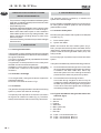
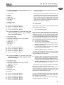
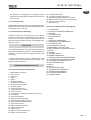
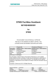
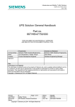
mase GENERATORS MANUALE DI INSTALLAZIONE I GENSET INSTATION MANUAL GB I.S. 18 / 21 / 24 / 27 50 Hz REV.1 S.S. 03 / 11 / 2003 cod.42403 Tipo modello N° matricola Codice I.S. 18 / 21 / 24 / 27 50 Hz 1224 110 190 807,5 710 680 630 680 132 110 7 2, Ø1 Fig. 1 1 Fig. 2 2 Fig. 3 Fig. 4 -2 I.S. 18 / 21 / 24 / 27 50 Hz 1219 Fig. 5 150 1219 Fig. 6 Fig. 7 -3 I.S. 18 / 21 / 24 / 27 50 Hz Fig. 9 Fig. 8 Valvola antisifone Anti-siphon valve Soupape antisiphon Beluchter Fig.11 Fig.10 4 3 2 1 Fig.12 -4 I.S. 18 / 21 / 24 / 27 50 Hz 1 1 Fig.14 Fig.13 RETE MAINS RESEAU GEN. 1 CARICO LOAD CHARGE 2 Fig.15 Fig.16 -5 I.S. 18 / 21 / 24 / 27 50 Hz WIRING DIAGRAM STANDARD -6 100Kohm 60HZ 1 3 5 3A 5C 4 6 5A 7 5B A.V.R. Cod. 45727 Fig.17 I.S. 18 / 21 / 24 / 27 50 Hz WIRING DIAGRAM STANDARD POLI ISOLATI Cod. 45765 Fig.18 -7 I.S. 18 / 21 / 24 / 27 50 Hz I INDICE Figure ..................................................................... 2 Schema elettrico ................................................... 6 1 INFORMAZIONI GENERALI ............................ 9 1.1 1.2 Scopo e campo di applicazione del manuale . 9 Simbologia ..................................................... 9 2 Prescrizioni per la sicurezza durante ............ l'installazione e la messa in servizio ......... 10 3 INSTALLAZIONE ........................................... 10 3.1 3.2 3.3 4 Caratteristiche del vano ................................ 10 Ancoraggio del gruppo .................................. 10 Ventilazione ................................................. 10 CIRCUITO ACQUA DI RAFFREDDAMENTO . 10 4.1 Sistema di adduzione dell'acqua di mare ...... 10 4.2.1 Tipica installazione con gruppo elettrogeno sopra la linea di galleggiamento (fig.4) .......... 11 4.2.2 Tipica installazione con gruppo elettrogeno sotto la linea di galleggiamento (fig.5) .................... 11 4.4.3 Tipica installazione di gruppo elettrogeno con marmitta separatrice acqua/gas di scarico tipo "GENSEP" sopra la linea di galleggiamento (fig.6) ............................................................ 11 4.4.4 Tipica installazione di gruppo elettrogeno con marmitta separatrice acqua/gas di scarico tipo "GENSEP" sotto la linea di galleggiamento (fig.7) ............................................................ 11 4.3 Componenti .................................................. 11 4.4 Sistema di scarico ........................................ 12 5 CIRCUITO COMBUSTIBILE .......................... 12 6 COLLEGAMENTI ELETTRICI ........................ 12 6.1 6.2 6.3 6.4 6.5 I -8 Allacciamento batteria .................................. 12 Collegamento pannello comando a distanza . 13 Allacciamento c.a. ........................................ 13 Collegamento di terra .................................... 13 Commutazione generatore - rete ................... 13 7 MOVIMENTAZIONE ....................................... 13 8 RIFERIMENTI SCHEMA ELETTRICO ............ 13 I.S. 18 / 21 / 24 / 27 50 Hz I 1 INFORMAZIONI GENERALI Consultare attentamente questo manuale prima di procedere a qualsiasi intervento sulla macchina. IL MANCATO RISPETTO DELLE SPECIFICHE CONTENUTE NEL SEGUENTE MANUALE DI USO E MANUTEZIONE COMPORTA IL DECADIMENTO DELLA GARANZIA SUL PRODOTTO 1.1 Scopo e campo di applicazione del manuale Grazie per aver scelto un prodotto mase. Questo manuale è stato redatto dal Costruttore allo scopo di fornire le informazioni e le istruzioni essenziali per effettuare, correttamente e in condizioni di sicurezza l'installazione, e costituisce parte integrante del corredo del gruppo elettrogeno e deve essere conservato con cura da qualsiasi agente che potrebbe deteriorarlo per tutto il ciclo di vita dello stesso. Il presente manuale deve seguire il gruppo elettrogeno qualora questo sia trasferito ad un nuovo utente o proprietario. Le informazioni in esso contenute sono dirette a tutte le persone coinvolte nel ciclo di vita operativo del gruppo elettrogeno e sono necessarie per informare sia chi materialmente effettuerà le diverse attività, sia chi dovrà coordinarle, predisporre la necessaria logistica e regolamentare gli accessi al luogo dove sarà installato ed opererà il gruppo elettrogeno. Il manuale definisce lo scopo per cui la macchina è stata costruita e contiene tutte le informazioni necessarie per garantirne un uso sicuro e corretto. La costante osservanza delle indicazioni, in esso contenute, garantisce la sicurezza delloperatore, leconomia desercizio ed una maggiore durata della macchina stessa. Si consiglia vivamente di leggere attentamente quanto contenuto in questo manuale e nei documenti di riferimento; solo così viene assicurato il regolare funzionamento nel tempo del gruppo elettrogeno, la sua affidabilità e la salvaguardia da danni a persone e cose. I disegni sono forniti a scopo esemplificativo. Anche se la macchina in vostro possesso si differenzia sensibilmente dalle illustrazioni contenute in questo manuale la sicurezza e le informazioni sulla stessa sono garantite. Per facilitare la consultazione esso è stato suddiviso in sezioni che ne identificano i concetti principali; per una consultazione rapida degli argomenti consultare lindice descrittivo. Nota: le informazioni contenute in questa pubblicazione sono corrette al momento della stampa. Il Costruttore, nel perseguire una politica di costante sviluppo ed aggiornamento del prodotto, si riserva di apportare modifiche senza preavviso. 1.2 Simbologia Le parti di testo da non trascurare sono state evidenziate in grassetto e precedute da simboli qui di seguito illustrati e definiti. Indica che è necessario prestare attenzione al fine di non incorrere in serie conseguenze che potrebbero provocare la morte, o possibili danni alla salute, del personale. Situazione che potrebbe verificarsi durante il periodo di vita di un prodotto, sistema o impianto considerato a rischio in materia di danni alle persone, alle proprietà, allambiente o di perdite economiche. Indica che è necessario prestare attenzione al fine di non incorrere in serie conseguenze che potrebbero portare al danneggiamento di beni materiali quali le risorse o il prodotto Indicazioni di particolare importanza. I -9 I.S. 18 / 21 / 24 / 27 50 Hz I 2 PRESCRIZIONI PER LA SICUREZZA DURANTE 4 CIRCUITO ACQUA DI RAFFREDDAMENTO L'INSTALLAZIONE E LA MESSA IN SERVIZIO Il motore del gruppo elettrogeno viene raffreddato da un sistema a circuito chiuso con scambiatore di calore. - Il personale incaricato all'installazione o messa in opera del gruppo elettrogeno dovrà sempre usare casco protettivo; indossare scarpe antinfortunistiche e la tuta. - Usare guanti antinfortunistici. - Non lasciare parti smontate, attrezzi o quant'altro non facente parte dell'impianto sul motore o nelle vicinanze. - Non lasciare mai liquidi infiammabili o stracci imbevuti di liquido infiammabile in prossimità del gruppo elettrogeno, vicino ad apparecchiature elettriche (incluse lampade) o parti d'impianto elettrico. - Prendere precauzioni per evitare il pericolo di folgorazioni. 3 INSTALLAZIONE 3.1 Caratteristiche del vano Il generatore deve essere installato in un locale sufficientemente aerato, in grado di assicurare la poca quantità d'aria necessaria alla combustione del motore. Il locale deve essere separato ed isolato acusticamente dalle aree abitabili. Il generatore va posizionato in modo da facilitare le normali operazioni di manutenzione. E' consigliabile l'installazione nel locale dei motori di propulsione a patto che questo sia conforme alle condizioni sopracitate. 3.2 Ancoraggio del gruppo Per il fissaggio del gruppo, predisporre un basamento per sopportare peso e vibrazioni. Procedere alla foratura del basamento seguendo le indicazioni di fig.1. 3.3 Ventilazione Il generatore è dotato di un sistema interno di raffreddamento forzato attraverso uno scambiatore acqua/aria. La quantità di aria necessaria alla combustione viene aspirata tramite l'apertura posta sul basamento (fig. 2): assicurarsi quindi che questa apertura sia sempre ben libera. I - 10 All'atto dell'installazione è necessario predisporre un circuito di adduzione dell'acqua di mare per il raffreddamento e un sistema di scarico per la miscela di gas di combustione ed acqua. 4.1 Sistema di adduzione dell'acqua di mare Sulle imbarcazioni i sistemi normalmente adottati per l'immissione dell'acqua sono due (fig. 3). 1 - Sistema a presa diretta 2 - Sistema con deflettore La MASE raccomanda il sistema a presa diretta (fig.3, rif.1) in quanto questo sistema previene l'ingresso di acqua in pressione nei condotti di aspirazione, generando invece una depressione facilmente superabile dalla prevalenza della pompa acqua del gruppo elettrogeno. Non applicare nessun tipo di cuffia di protezione al sistema a presa diretta. Il sistema con deflettore può invece causare i seguenti inconvenienti: a - Se viene montato con le asole rivolte verso la prua. In questo caso durante la navigazione e con gruppo elettrogeno spento si crea una pressione nel condotto immissione acqua, che può causare il riempimento dell'impianto, fino al raggiungimento delle luci di scarico rendendo così possibile l'ingresso di acqua nei cilindri. b - Se viene montato con le asole rivolte verso la poppa. In questo caso durante la navigazione si può creare una depressione nel condotto immissione acqua, tale da impedire alla pompa acqua di innescare l'impianto di raffreddamento o tale da limitare la portata con conseguente surriscaldamento del gruppo elettrogeno. I.S. 18 / 21 / 24 / 27 50 Hz 4.2.1 Tipica installazione con gruppo elettrogeno sopra la linea di galleggiamento (fig.4) 1 2 3 4 5 6 7 Scarico a mare Silenziatore Marmitta Filtro acqua Rubinetto generale impianto Presa a mare Rubinetto di svuotamento A - Tubazione diametro interno Ø75 mm. B - Tubazione diametro interno Ø25 mm. C - Tubazione diametro interno Ø16 mm. 4.2.2 Tipica installazione con gruppo elettrogeno sotto la linea di galleggiamento (fig.5) 1 2 3 4 5 6 7 8 9 Scarico a mare Silenziatore Marmitta Filtro acqua Rubinetto generale impianto Presa a mare Rubinetto di svuotamento Valvola antisifone Drenaggio A B C D - Tubazione diametro interno - Tubazione diametro interno - Tubazione diametro interno - Tubazione diametro interno I 4.4.4 Tipica installazione di gruppo elettrogeno con marmitta separatrice acqua/gas di scarico tipo "GENSEP" sotto la linea di galleggiamento (fig.7) 1 2 3 4 5 6 7 8 9 10 Scarico a mare - Gas Scarico a mare - Acqua Marmitta separatrice gas/acqua tipo GENSEP Marmitta VERNALIFT Filtro acqua Rubinetto generale impianto Presa a mare Rubinetto di svuotamento Valvola antisifone Drenaggio A B C D E F - Tubazione diametro interno - Tubazione diametro interno - Tubazione diametro interno - Tubazione diametro interno - Tubazione diametro interno - Tubazione diametro interno Ø80 mm. Ø40 mm. Ø25 mm. Ø25 mm. Ø16 mm. Ø14 mm. - E' molto importante rispettare le misure riportate negli gli schemi d'installazione Ø75 mm. Ø25 mm. Ø16 mm. Ø14 mm. 4.4.3 Tipica installazione di gruppo elettrogeno con marmitta separatrice acqua/gas di scarico tipo "GENSEP" sopra la linea di galleggiamento (fig.6) 1 2 3 4 5 6 7 8 Scarico a mare - Gas Scarico a mare - Acqua Marmitta separatrice gas/acqua tipo GENSEP Marmitta VERNALIFT Filtro acqua Rubinetto generale impianto Presa a mare Rubinetto di svuotamento A B C D E - Tubazione diametro interno - Tubazione diametro interno - Tubazione diametro interno - Tubazione diametro interno - Tubazione diametro interno Ø80 mm. Ø40 mm. Ø25 mm. Ø25 mm. Ø16 mm. - Le marmitte (rif.3 di fig.4 e 5 ) hanno il compito di raccogliere l'acqua presente nelle tubazioni di scarico quando viene spento il motore del gruppo elettrogeno ed impedire che questa defluisca all'interno del motore attraverso il collettore e la valvola di scarico. Per tale motivo è indispensabile rispettare la posizione della marmitta e la lunghezza delle tubazioni come indicato sullo schema d'installazione. 4.3 Componenti Il sistema di presa acqua di mare deve essere indipendente da quello dei motori di propulsione della barca 1 - Presa a mare del tipo diretto 1/2". Nel caso il gruppo venga installato ad un altezza superiore ad 1 mt. sopra la linea di galleggiamento, è necessario montare una valvola di non ritorno dopo la presa a mare (fig.8, rif.1) che impedisce lo svuotamento del circuito acqua a motore spento. In caso di svuotamento, durante l'avviamento si può danneggiare la girante della pompa acqua; per lo stesso motivo all'atto del primo avviamento del gruppo, è necessario provvedere al riempimento manuale del tubo di aspirazione dalla valvola alla pompa. I - 11 I.S. 18 / 21 / 24 / 27 50 Hz I 2 - Rubinetto a sfera (Generale impianto) 1/2". 3 - Rubinetto a sfera (Spurgo impianto) 1/2". Serve a vuotare l'impianto di raffreddamento del gruppo elettrogeno per manutenzioni generali o per periodi di lunga inattività. 4 - Filtro acqua (ispezionabile). Deve proteggere efficacemente il circuito di raffreddamento dall'ingresso di fango, sabbia e alghe. Portata acqua IS 21.5-23.5: 40-45 L/min. La rete filtrante dovrà essere del tipo fine. Si consiglia il tipo con passo 2 - 470 micron, misure diverse non consentirebbero un buon rendimento del filtro. 5 - Valvola antisifone: è una valvola che riporta a pressione atmosferica il circuito di raffreddamento a motore spento, evitando il fenomeno di sifonaggio. Va obbligatoriamente usata quando la base del gruppo elettrogeno si trova sotto la linea di galleggiamento, e va posizionato ad almeno 50 cm sopra il livello del mare. (vedi fig.5). La valvola antisifone va inserita tra la mandata della pompa acqua di mare e il miscelatore come indicato alla fig.11. Il condotto di drenaggio della valvola antisifone deve obbligatoriamente viaggiare al di sotto della stessa impedendo così accumuli di acqua nel condotto, che deve rimanere sempre vuoto, per permettere il passaggio di aria nello stesso al momento dello spegnimento del gruppo (vedi fig.9). Si consiglia di portare il condotto di drenaggio della valvola antisifone in sentina, perché dallo stesso, durante il normale funzionamento, potrebbero fuoriuscire piccole quantità di acqua. Il circuito di raffreddamento va collegato al raccordo dello scambiatore come indicato dalla figura 10. 4.4 Sistema di scarico Il sistema di scarico gas di combustione/acqua del generatore deve essere indipendente da quello dei motori principali. La lunghezza del tubo dal punto più alto del condotto di scarico alla marmitta non deve superare mt. 2. Questo per evitare che allo spegnimento del gruppo l'acqua rimasta nel condotto di scarico possa rifluire al motore dopo aver riempito la marmitta a barilotto. I - 12 1 - Marmitta. Attenua la rumorosità dello scarico ed impedisce il riflusso dell'acqua verso il motore. Si consiglia di installare la marmitta a non più di 1 mt. dal generatore e di posizionarla ad una altezza come da fig.4,5,6,7. 2 - Silenziatore. Riduce ulteriormente la rumorosità. Si consiglia di installarlo ad una distanza non superiore ad 1 mt. dal bocchettone di scarico a mare. 3 - Bocchettone di scarico a mare. Va installato in posizione tale da essere sempre sopra il livello del mare in tutte le condizioni di utilizzo dell'imbarcazione. 5 CIRCUITO COMBUSTIBILE L'alimentazione del gruppo è a gasolio, ed avviene tramite i raccordi contrassegnati dalle diciture "fuel inlet" (fig.12 rif.2) e "fuel outlet" (fig.12 rif.3); quest'ultimo serve per il ritorno del combustibile in eccesso. Nel collegamento al serbatoio combustibile non sono necessari elementi filtranti, in quanto è già presente sul gruppo un filtro combustibile; è invece buona norma inserire un rubinetto sulla linea di alimentazione a valle del serbatoio, ed una valvola unidirezionale (di non ritorno) onde evitare lo svuotamento dell'impianto combustibile per qualsiasi causa. Utilizzare una valvola con apertura 50 millibar (Prevalenza max 0.8 M). I tubi del combustibile devono essere in gomma resistente agli idrocarburi, di diametro interno 8 mm. Per ulteriori informazioni, attenersi al libretto uso e manutenzione del costruttore del motore. 6 COLLEGAMENTI ELETTRICI 6.1 Allacciamento batteria Per l'avviamento del gruppo è necessario utilizzare una batteria indipendente a 12V, di capacità 100 Ah. La batteria non dovrà essere inferiore alla capacità indicata. Essa va allacciata ai morsetti del generatore (fig.12 rif.4) con cavi di sez. 25 mm2 fino a distanze di 5 mt., con cavi di sez. 35 mm2 per distanze maggiori, rispettando questa sequenza di operazioni: - Collegare prima il polo positivo (+) della batteria al terminale contrassegnato dal simbolo (+) sul generatore. - Collegare successivamente il polo negativo (-) della batteria al terminale contrassegnato dal simbolo (-) sul generatore. I.S. 18 / 21 / 24 / 27 50 Hz - Cospargere le connessioni con specifico grasso minerale, al fine di ridurre ossidazioni o corrosioni. Il generatore è dotato di un dispositivo elettronico per la ricarica automatica della batteria di avviamento, capace di erogare 40 A, ad una tensione di 12V, a pieno carico. Installare la batteria in un vano aerato, separato dal generatore e da ogni dispositivo che possa provocare calore o scintille. Verificare periodicamente lo stato delle connessioni dei morsetti ed il livello acqua batteria. Nel caso si renda necessario scollegare i cavi, agire inversamente all'ordine raccomandato nel collegarli. Non invertire le polarità dei cavi di connessione; il generatore e la batteria potrebbero esserne seriamente danneggiati. Non collegare altri carichi alla batteria. Al fine di minimizzare le correnti galvaniche il (-) della batteria del gruppo elettrogeno non deve essere collegato al (-) delle altre batterie di bordo. 6.2 Collegamento pannello comando a distanza Sono disponibili due modelli di pannello comando remoto, installabili in plancia, che possono essere collegati al gruppo elettrogeno per eseguire lavviamento e larresto. Entrambi i modelli sono forniti con cavo elettrico di collegamento lungo 20 mt. predisposto con connettore di collegamento alle estremità Fissare il connettore del cavo di collegamento nellapposito innesto posto sulla parte inferiore della scatola cruscotto interna al gruppo elettrogeno (fig.15 rif.1) e la parte opposta al pannello di comando remoto. 6.3 Allacciamento c.a. Questo collegamento è eseguibile direttamente sul magnetotermico di macchina posto sul quadro del gruppo elettrogeno (fig.14 rif.1). Si accede al magnetotermico dopo aver rimosso il pannello di chiusura come indicato alla fig.13 rif.1. - Assicurarsi che la somma dei carichi da alimentare non superi la potenza nominale del gruppo elettrogeno. - Il gruppo elettrogeno è dotato di una protezione magnetotermica che interrompe l'erogazione di corrente in caso di sovraccarico o cortocircuito. 6.4 Collegamento di terra La carcassa del gruppo elettrogeno deve essere solidamente collegata a terra. Eseguire il collegamento di terra utilizzando l'apposita vite del gruppo elettrogeno Fig. 15 Rif. 2. I 6.5 Commutazione generatore - rete E' necessario interporre sulla linea di utilizzo un commutatore che permetta di commutare le utenze dal generatore ad una linea di alimentazione esterna. Il commutatore va dimensionato in base all'entità dei carichi in gioco; uno schema di massima è rappresentato in fig.16. 7 MOVIMENTAZIONE Per la movimentazione del gruppo elettrogeno ed il suo sollevamento utilizzare solo gli appositi ganci di sollevamento posti sul motore. Per problemi di bilanciatura, utilizzare contemporaneamente i ganci e mai singolarmente. Agganciare il gruppo elettrogeno in punti diversi da quelli indicati potrebbe causare danni al gruppo stesso o diventare pericoloso per gli operatori 8 RIFERIMENTI SCHEMA ELETTRICO Vedere fig.17 (Schema elettrico Standard) 1 2 3 4 5 6 7 8 9 10 11 12 13 14 15 16 17 18 19 20 21 22 23 24 25 26 27 Interruttore magnetotermico Contaore Alternatore Rotore Statore Regolatore di tensione Morsettiera di potenza Pulsante arresto emergenza Interruttore termico Pulsante START / STOP Modulo protezione motore Morsettiera Connettore per collegamento pannello a distanza Indicato relivello carburante Indicatore di pressione olio Indicatore di temperatura acqua Sensore alta temperatura acqua Sensore alta temperatura liquido refrigerante Pressostato olio Alternatore carica batteria Elettromagnete stop Motorino davviamento Morsetti di collegamento batteria Cavo di collegamento pannello Pulsante START / STOP Strumento indicatore pressione olio Strumento indicatore temperatura liquido refrigerante 28 Kit pannello comando a distanza con strumenti 29 Kit pannello comando a distanza 30 - Vite di terra I - 13 I.S. 18 / 21 / 24 / 27 50 Hz I Vedere fig.18 (Schema elettrico poli isolati) 1 2 3 4 5 6 7 8 9 10 11 12 13 14 15 16 17 18 19 20 21 22 23 24 25 26 27 I - 14 ALTERNATORE ALTERNATORE RICARICA BATTERIA BATTERIA CONNETTORE 12P CONTAORE DIODO ELETTROMAGNETE STOP MODULO PROTEZIONE MOTORE MOTORINO DI AVVIAMENTO PRESSOSTATO OLIO PULSANTE ARRESTO DI EMERGENZA REGOLATORE ELETTRONICO DI TENSIONE ROTORE STATORE TERMICO TERMOSTATO MOTORE STRUMENTO INDICATORE TEMPERATURA STRUMENTO INDICATORE PRESSIONE OLIO MAGNETOTERMICO 2P COLLEGAMENTO DI TERRA RELE RELE PULSANTE START-STOP TERMOSTATO ALTERNATORE SENSORE TEMPERATURA SENSORE PRESSIONE OLIO CONNETTORE 6P I.S. 18 / 21 / 24 / 27 50 Hz I I - 15 I.S. 18 / 21 / 24 / 27 50 Hz GB INDEX Pictures .................................................................. 2 Wiring diagram ...................................................... 6 1 General information ...................................... 9 2 Prescriptions for safety during installation and set-up .................................................... 10 3 INSTALLATION ............................................. 10 3.1 3.2 3.3 4 Housing characteristics ................................ 10 Generator anchorage .................................... 10 Ventilation .................................................... 10 COOLING WATER CIRCUIT ......................... 10 4.1 Seawater feed system .................................. 10 4.2.1 Typical installation with generator above the waterline (fig.4) ............................................. 10 4.2.2 Typical installation with generator below the water line (Fig.5) ........................................... 11 4.4.3 Typical installation of generator with gas/water separating exhaust type GENSEP above the waterline (fig.6) ............................................. 11 4.4.4 Typical installation of generator with gas/water separating exhaust type GENSEP below the waterline (fig.7) ............................................. 11 4.3 Components ................................................. 11 4.4 Exhaust system ........................................... 12 5 FUEL CIRCUIT .................................................. 12 6 ELECTRICAL CONNECTIONS .......................... 12 6.1 6.2 6.3 6.4 6.5 GB - 8 Battery connection ....................................... 12 Remote control panel connection .................. 12 AC connection .............................................. 12 Earth connection .......................................... 13 Generator/mains switching ........................... 13 7 HANDLING .................................................... 13 8 WIRING DIAGRAM REFERENCES ................ 13 I.S. 18 / 21 / 24 / 27 50 Hz GB 1 GENERAL INFORMATION Carefully consult this manual before using or carrying out any operation on the generator. FAILURE TO RESPECT THE SPECIFICATIONS CONTAINED IN THIS USE AND MAINTENANCE MANUAL WILL RESULT IN FORFEITURE OF THE GUARANTEE ON THE PRODUCT. 1.1 Purpose and field of application of the manual This manual was drawn up by the manufacturer and forms an integral part of the generator equipment, definition used as indicated in Directive 98/37 EEC; the information contained in the manual is addressed to all the persons involved in the operating life cycle of the generator, and is necessary to inform both those who effectively carry out the different operations and those who coordinate the activities, to arrange the necessary logistics and to regulate access to the place where the generator will be installed and operated. This manual was drawn up by the manufacturer with the purpose of providing essential information and instructions for proper use and maintenance in conditions of safety. It constitutes an integral part of the generator equipment and must carefully be protected from any agent which may damage it for the entire life cycle of the generator. The manual must accompany the generator if transferred to another user or owner. The manual defines the purpose for which the generator was constructed and contains all the information necessary to guarantee safe and proper use. Constant observance of the instructions contained in this manual guarantees the safety of the operator, protection against damage to persons or things, operating economy and a longer life of the generator. The drawings are provided by way of example. Even if the generator in your possession differs from the illustrations contained in this manual in elements of little significance, for example the colour, the safety of the generator and the information provided are nevertheless guaranteed. To facilitate consultation, it has been divided into sections identifying the main concepts; for a quick look at the topics, consult the index. Ongoing improvement and development of the product may have led to modifications to the generator which are not included in this publication. Whenever a problem concerning the generator or this publication arises, consult with Mase Generators SPA for the latest information available. 1.2 Symbology, definitions and manual informations Those parts of the text not to be ignored are highlighted in bold type preceded by a symbol, as illustrated and defined below. Indicates that particular attention must be paid in order to prevent running serious risks which could lead to death or possible harm to the health of personnel. A condition which may occur during the lifetime of a product, system or plant considered at risk regarding damage to persons, property, the environment or economic loss. Indicates that particular attention must be paid in order to prevent serious consequences which could result in damage to tangible goods, such as the resources or the product. Instructions of particular importance. GB -9 I.S. 18 / 21 / 24 / 27 50 Hz GB 2 PRESCRIPTIONS FOR SAFETY DURING INSTALLATION AND SET-UP - The personnel in charge of installation and starting of the generator must always wear a protective helmet; wear safety shoes and overalls. - Use protective gloves. - Do not leave disassembled parts, tools or anything else not forming part of the system on or near the engine. - Never leave inflammable liquids or cloths soaked in inflammable liquids in proximity of the generator, near electric equipment (including lamps) or parts of the electrical system. - Take the necessary precautions to prevent the danger of electrocution. 3 INSTALLATION 3.1 Housing characteristics The generator must be installed in a sufficiently ventilated room able to guarantee the small amount of air necessary for engine combustion. The room must be acoustically separated and isolated from the living quarters. The generator must be positioned in such a way as to facilitate routine maintenance operations. Installation in the propulsion engine room is advisable provided that it conforms to the above mentioned conditions. 3.2 Generator anchorage To fix the generator, arrange for a base to support the weight and vibrations. Drill holes in the base as shown in Fig.1. 3.3 Ventilation The generator is equipped with an internal forced cooling system by means of a water/air exchanger. The quantity of air required for combustion is sucked in through the air intake on the base (Fig. 2): Therefore, always check that this intake is free of any obstruction. 4 COOLING WATER CIRCUIT The generator engine is cooled by a closed-circuit system with heat exchanger. During installation a seawater feed circuit must be set up for cooling and an exhaust system for the combustion gas and water mixture. 4.1 Seawater feed system Normally two types of water intake systems are adopted on boats (Fig. 3). 1 - Direct intake system 2 - System with baffle MASE recommends the direct intake system (Fig.3, Ref.1) as it prevents inflow of pressurised water into the intake ducts, instead generating a vacuum which the pressure head of the the generator water pump can easily override. Do not fit any type of protection cap on the direct intake system. The system with baffle may cause the following problems: a - If mounted with the slots facing the bow: In this case during navigation and with the generator off, pressure is created in the water intake duct, which may cause the system to fill until reaching the exhaust ports and hence water may enter the cylinders. b - If mounted with the slots facing the stern: In this case during navigation a vacuum may be created in the water intake duct such as to prevent the water pump from activating the cooling system or such as to limit the throughput with consequent overheating of the generator. 4.2.1 Typical installation with generator above the waterline (fig.4) 1 2 3 4 5 6 7 Sea exhaust Silencer Exhaust Water filter Main system tap Sea intake Drain tap A - Pipes - inner diameter Ø75 mm. B - Pipes - inner diameter Ø25 mm. C - Pipes - inner diameter Ø16 mm. GB - 10 I.S. 18 / 21 / 24 / 27 50 Hz GB 4.2.2 Typical installation with generator below the water line (Fig.5) - It is very important to respect the distances shown in the installation diagrams. 1 2 3 4 5 6 7 8 9 Sea exhaust Silencer Exhaust Water filter Main system tap Sea intake Drain tap Antisiphon valve Drainage - The exhausts (ref.3 of fig.4 and 5 ) have the function of collecting the water left in the exhaust pipes when the generator engine is turned off and preventing that it flows into the engine through the manifold and the exhaust valve. For this reason it is essential to respect the position of the exhaust and the length of the pipes as indicated in the installation diagram. A B C D - Pipes - inner diameter Ø75 mm. - Pipes - inner diameter Ø25 mm. - Pipes - inner diameter Ø16 mm. - Pipes - inner diameter Ø14 mm. 4.4.3 Typical installation of generator with gas/ water separating exhaust type GENSEP above the waterline (fig.6) 1 2 3 4 5 6 7 8 Sea exhaust - gas Sea exhaust - water Gas/water separating exhaust type GENSEP VERNALIFT exhaust Water filter Main system tap Sea intake Drain tap A B C D E - Pipes - inner diameter Ø80 mm. - Pipes - inner diameter Ø40 mm. - Pipes - inner diameter Ø25 mm. - Pipes - inner diameter Ø25 mm. - Pipes - inner diameter Ø16 mm. 4.4.4 Typical installation of generator with gas/ water separating exhaust type GENSEP below the waterline (fig.7) 1 2 3 4 5 6 7 8 9 10 Sea exhaust - gas Sea exhaust - water Gas/water separating exhaust type GENSEP VERNALIFT exhaust Water filter Main system tap Sea intake Drain tap Antisiphon valve Drainage A B C D E F - Pipes - inner diameter Ø80 mm. - Pipes - inner diameter Ø40 mm. - Pipes - inner diameter Ø25 mm. - Pipes - inner diameter Ø25 mm. - Pipes - inner diameter Ø16 mm. - Pipes - inner diameter Ø14 mm. 4.3 Components The seawater intake system must be independent of that of the boat propulsion engines 1 - 1/2" direct seawater intake. If the generator is installed at a height of over 1 m above the water line, a non-return valve must be fitted after the seawater intake (Fig.8, Ref.1) to prevent draining the water circuit when the engine is off. If it is drained, the water pump rotor may be damaged during starting; for the same reason, when the generator is started for the first time, the intake pipe must be filled manually from the valve to the pump. 2 - 1/2" ball cock (main system). 3 - 1/2" ball cock (system bleeding). Serves to drain the cooling system of the generator for general maintenance or for long periods of inactivity. 4 - Water filter (inspectable). It must efficiently protect the cooling circuit against inflow of mud, sand and seaweed. Water flow rate IS 21.5-23.5: 40-45 l/min. The filter mesh must be the fine type. It is recommended to use the type with pitch 2 - 470 micron; different sizes would not allow good filter efficiency. 5 - Antisiphon valve: This is a valve which pressurizes the cooling circuit to atmospheric pressure when the engine is off, preventing the siphonage phenomenon. It must be used when the base of the generator sits below the water line, and must be positioned at least 50 cm above sea level. (see Fig.5). The antisiphon valve is inserted between the seawater pump delivery and the mixer as shown in Fig.11. The antisiphon valve drain pipe must run below it thus preventing water from building up in the pipe, which must always remain empty to allow air to pass through it when the generator is switched off (see Fig.9). It is recommended to lead the antisiphon valve drain pipe into the bilge, since small amounts of water might seep from it during normal operation. The cooling circuit is connected to the heat exchanger pipe fitting as shown in Figure 10. GB - 11 I.S. 18 / 21 / 24 / 27 50 Hz GB 6 ELECTRICAL CONNECTIONS 4.4 Exhaust system The combustion gas/water exhaust system of the generator must be independent of that of the main engines. The pipe length from the highest point of the exhaust pipe to the exhaust must not exceed 2 m. This is to prevent that when the generator is switched off the water left in the exhaust pipe flows back to the engine after the exhaust has been filled. 1 - Exhaust Dampens the exhaust noise and prevents water backflow to the engine. It is recommended to install the exhaust not more than 1 m from the generator and to position it at a height as shown in Figures 4,5,6,7. 2 - Silencer Further reduces the noise. It is recommended to install the exhaust not more than 1 m from the sea exhaust union. 3 - Sea exhaust union It must be installed in such a position as to always be above sea level in all boating conditions. 5 FUEL CIRCUIT The generator is diesel-powered through the unions marked fuel inlet (Fig.12 Ref.2) and fuel outlet (Fig.12 Ref.3); the latter is for the return of excess fuel. No filter elements are required in the fuel tank connection since a fuel filter is already fitted on the generator; it is however good practice to fit a cock on the feed line downstream of the tank as well as a non-return valve in order to prevent the fuel system from emptying out for any reason. Use a valve with 50 millibar opening (max. head 0.8 M). The fuel pipes must be made of rubber resistant to hydrocarbons with an inside diameter of 8 mm. For further information, read the use and maintenance handbook of the engine manufacturer. 6.1 Battery connection To start the generator a stand-alone 12V battery is required with a capacity of 100 Ah. Do not use a battery with a capacity lower than that indicated. It is connected to the generator terminals (Fig.12 Ref.4) with cables of 25 mm2 cross-section for distances up to 5 m, and 35 mm2 cross-section for greater distances, in the following order: - First connect the positive pole (+) of the battery to the terminal marked with the symbol (+) on the generator. - Then connect the negative pole (-) of the battery to the terminal marked with the symbol (-) on the generator. - Spread specific mineral grease on the connections to reduce oxidation or corrosion. The generator is equipped with an electronic device for automatic charging of the starter battery, which can deliver 40 A at 12V at full power. Install the battery in a ventilated housing separate from the generator and any device which may produce heat or sparks. Periodically check the state of the terminal connections and the battery water level. If the cables need to be disconnected, work in reverse order from connection. Do not invert the polarities of the connection cables; the generator and the battery may be seriously damaged. Do not connect any other loads to the battery. In order to minimise galvanic currents, the (-) of the generator battery must not be connected to the (-) of other batteries on board. 6.2 Remote control panel connection There are two remote control panels available, installable on the bridge, which can be connected to the generator for starting and stopping. Both models are supplied with a 20 m electric connection cable with a connector fitted at the end. Fit the connector of the connection cable to the special coupling located at the lower part of the instrument panel casing inside the generator (fig.15 ref.1) and the opposite part to the remote control panel. 6.3 AC connection This connection can be made directly on the magnetothermal switch of the machine located on the generator panel (Fig. 14 Ref.1). The magnetothermal switch can be accessed after removing the closing panel as shown in Fig.13 Ref. 1. - Ensure that the sum of the loads to be fed does not exceed the rated output of the generator. GB - 12 I.S. 18 / 21 / 24 / 27 50 Hz GB - The generator is equipped with a magnetothermal switch which cuts the power in the event of an overload or short-circuit. 6.4 Earth connection The generator casing must be firmly connected to earth. Make the earth connection using the dedicated screw of the generator (Fig. 15 Ref. 2) 6.5 Generator/mains switching A switch must be put on the utility line, which allows switching the utilities from the generator to an external power line. The switch must be dimensioned on the basis of the entity of loads involved; A broad diagram is shown in Fig.16. 7 HANDLING For handling and lifting of the generator only use the lifting hooks located on the engine. To prevent balancing problems, use the hooks simultaneously and never individually. Hooking the generator at points different from that indicated may cause damage to the generator or be dangerous to the operators. 8 WIRING DIAGRAM REFERENCES See Fig.17 (standard wiring diagram) 1 2 3 4 5 6 7 8 9 10 11 12 13 14 15 16 17 18 19 20 21 22 23 24 Magnetothermal switch Hour counter Alternator Rotor Stator Voltage regulator Power terminal board Emergency stop button Thermal switch START/STOP button Engine protection module Terminal board Connector for remote control panel connection Fuel gauge Oil pressure gauge Water temperature gauge High water temperature sensor High coolant temperature sensor Oil pressure switch Battery charger alternator Stop electromagnet Starter motor Battery connection terminals Panel connection cable 25 26 27 28 29 3 START/STOP button Oil pressure gauge instrument Coolant temperature gauge instrument Remote control panel kit with instruments Remote control panel kit Ground screw See Fig.18 (isolated pole wiring diagram) 1 2 3 4 5 6 7 8 9 10 11 12 13 14 15 16 17 18 19 20 21 22 23 24 25 26 27 ALTERNATOR BATTERY CHARGER ALTERNATOR BATTERY 12P CONNECTOR HOUR COUNTER DIODE STOP ELECTROMAGNET ENGINE PROTECTION MODULE STARTER MOTOR OIL PRESSURE SWITCH EMERGENCY STOP BUTTON ELECTRONIC VOLTAGE REGULATOR ROTOR STATOR THERMAL SWITCH ENGINE THERMOSTAT TEMPERATURE GAUGE INSTRUMENT OIL PRESSURE GAUGE INSTRUMENT 2P MAGNETOTHERMAL SWITCH EARTH CONNECTION RELAY RELAY START/STOP BUTTON ALTERNATOR THERMOSTAT TEMPERATURE SENSOR OIL PRESSURE SENSOR CONNECTOR 6P GB - 13