1
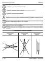
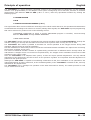
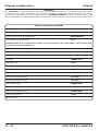
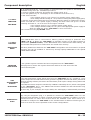
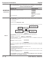
FCS-233si (Galileo)
Sistema Elettronico Feedback con Emulatore Stacca Iniettori incorporato
Electronic Feedback System with incorporated Cut Injectors Emulator
Cod. 105170 FCS-233si
Manuale Istruzioni di Montaggio
Fitting Instructions
Index
Italiano
•
•
•
•
•
•
•
Avvertenze generali
Principio di funzionamento Configurazione originale
Descrizione componenti
Schemi di collegamento SENSORI DI LIVELLO
Schemi di collegamento CABLAGGI STACCA INIETTORI
Schema d’installazione
3
4
5
6
10
11
12
General information
Principle of operation Original configuration Component description
FUEL LEVEL SENSOR wiring diagrams
CUT INJECTORS CABLES wiring diagrams
Installation diagram
13
14
15
16
20
21
22
English
•
•
•
•
•
•
•
EMMEGAS S.p.A
v. G. Falcone, 5
42021 Barco (RE) - Italy
Tel. +39 0522 246500
Fax +39 0522 246502
http://www.emmegas.net
E-mail: [email protected]
Avvertenze generali
Italiano
Dove fissare il Sistema Feedback:
- LONTANO da possibili INFILTRAZIONI D’ACQUA.
- LONTANO da ECCESSIVE FONTI DI CALORE (esempio collettori di scarico).
- LONTANO dai CAVI DELL’ALTA TENSIONE.
Fare delle buone connessioni elettriche evitando l’uso dei “RUBACORRENTE”.
Si tenga presente che la migliore connessione elettrica è la saldatura debitamente isolata.
Avvisare il cliente che in caso di rottura del fusibile dell’impianto a GAS, il Sistema Feedback
ripristina i collegamenti dei dispostivi a cui è collegato.
Non aprire per nessun motivo la scatola del Sistema Feedback soprattutto con il motore in moto o il
quadro inserito, onde evitare danni irreparabili.
EMMEGAS declina ogni responsabilità per danni a cose e persone derivati dalla manomissione
del proprio dispositivo da parte di personale non autorizzato con la conseguente perdita di
GARANZIA.
Come fissare il Sistema Feedback
INSTALLAZIONE
ERRATA
3 - 22
INSTALLAZIONE
ERRATA
INSTALLAZIONE
CORRETTA
195317000 Rev. 080610-0
Principio di funzionamento
Italiano
L’FCS-233si è un sistema per il controllo della carburazione sulle vetture a GAS, programmabile ed autoadattativo
gestito da microcontrollore, in grado di mantenere il rapporto stechiometrico ARIA/GAS (METANO o G.P.L.) in ogni
condizione di funzionamento, entro il valore ottimale, sfruttando i segnali di:
• SONDA LAMBDA
• NUMERO GIRI MOTORE • POSIZIONE FARFALLA ACCELERATORE (T.P.S.)
Per poter gestire correttamente il segnale di questi sensori, che a seconda del modello di vettura su cui sono installati possono avere caratteristiche di funzionamento diverse e, per poter adattare la centralina FCS-233si alle
diverse condizioni di funzionamento, è necessario programmarla correttamente tramite uno dei seguenti dispositivi:
• PERSONAL COMPUTER su cui sarà installato un apposito SOFTWARE di programmazione, tramite un’INTERFACCIA SERIALE per il collegamento tra computer e centralina FCS-233si
• TESTER PALMARE
La centralina FCS-233si ha incorporato al suo interno un Emulatore Stacca Iniettori con emulazione fissa che,
tramite l’apposito cablaggio, permette di interrompere e simulare il funzionamento degli iniettori durante l’utilizzo a
GAS della vettura.
Con l’FCS-233si è inoltre possibile simulare il corretto funzionamento della Sonda Lambda senza dover
aggiungere emulatori esterni.
La regolazione del GAS viene fatta tramite un attuatore elettromeccanico da porsi lungo il tubo che collega il
riduttore di pressione al miscelatore.
L’attuatore elettromeccanico è composto da un corpo in plastica con foro calibrato per il passaggio del GAS, su cui
è alloggiato un motore passo-passo in grado di dosare, a seconda della necessità, la giusta quantità di GAS.
Essendo questo un sistema autoadattativo non necessita di aggiustamenti periodici. L’unica regolazione manuale da
effettuare è quella del minimo sul riduttore ed è importante che sia fatta con la massima precisione.
L’FCS-233si controlla la carburazione anche al minimo, ma se la regolazione del riduttore non è ottimale
(miscela troppo ricca o troppo povera) non può effettuare delle grosse variazioni, il suo scopo è quello di
effettuare solo una regolazione fine della carburazione al minimo.
La centralina FCS-233si inoltre, gestisce direttamente il funzionamento dell’elettrovalvole del GAS.
Il commutatore in dotazione è utilizzato per la selezione del tipo di carburante.
195317000 Rev. 080610-0
4 - 22
Configurazione originale
Italiano
ATTENZIONE!
L’FCS-233si viene fornito configurato con i parametri riportati in tabella, si tenga presente che non tutte le
vetture hanno le stesse caratteristiche, quindi è necessario verificare di volta in volta che questi siano corretti.
Nel caso in cui, dopo aver effettuto delle modifiche ai vari parametri, tramite il COMPUTER o tramite il TESTER
PALMARE si utilizzi la funzione [CANCELLAZIONE MEMORIA], questi verranno automaticamente riportati nella
configurazione originale (vedi tabella riportata di seguito).
MENÙ DI CONFIGURAZIONE VETTURA
Tipo di accensioneo numero cilindri
BIBOBINA
Tipo di segnale giri
STANDARD
Tipo di cambio Benzina-Gas
DECELERAZIONE
Temperatura per il cambio
25 °C
Se alla centralina FCS-233si non è collegato l’apposito sensore di temperatura, questa funzione
non ha alcuna influenza sul cambio BENZINA-GAS.
Numero di giri per il cambio
Benzina-Gas
2000 RPM
Tempo sovrapposizione carburanti
0,4 secondi
Tipo di sensore livello Gas
A.E.B.
Tipo di TPS
LINEARE 0-5 V
Tipo di Sonda Lambda
0-1 V
Ritardo lettura Sonda Lambda
5 secondi
Tipo di emulazioneSonda Lambda ONDA QUADRA
Opzione default bloccato
NON ABILITATA
Massima apertura attuatore
240 passi
Minima apertura attuatore
20 passi
Opzione affondata
NON ABILITATA
Opzione Cut-Off
NON ABILITATA
Opzione guida economica
NON ABILITATA
Isteresi sul minimo TPS
0,14 V
Cancellazione memoria
5 - 22
195317000 Rev. 080610-0
Descrizione componenti
+12 VOLT
SOTTO CHIAVE
FILO ROSSO
+12 VOLT
BATTERIA
FILO
ROSSO-NERO
EMULAZIONE
INIETTORI
USCITA
SERVIZI GAS
FILO BLU
PRESA
DIAGNOSI
Italiano
È estremamente importante che l’alimentazione +12 V sotto chiave sia collegata in un
punto dove la tensione non sia temporizzata o manchi durante l’avviamento.
Procedura di verifica:
• collegare un multimetro selezionando la portata in tensione 20 V;
• inserire il quadro, sul display deve comparire l’indicazione 12 V;
• attendere qualche secondo:
- se la tensione va a 0 V è temporizzata, quindi provare in un’altra posizione;
- se la tensione rimane a +12 V proseguire nella prova;
• effettuare l’avviamento verificando con il multimetro che la tensione, nel momento in cui
inizia a girare il motorino di avviamento non vada a 0 V per poi tornare a +12 V non appena
si rilascia la chiave a motore avviato:
- se la tensione va a 0 V, provare in un’altra posizione;
- se la tensione rimane a +12 V, questa è la posizione corretta dove collegare il filo
ROSSO dell’FCS-233si.
Si raccomanda di utilizzare fusibili MAX 7,5 A.
Il filo ROSSO-NERO collegato al positivo della batteria tramite il fusibile di protezione
(MAX. 7,5 A) permette alla centralina dell’FCS-233si di mantenere in memoria i dati
relativi alla carburazione (valore di DEFAULT).
Se viene sconnesso il filo ROSSO-NERO dalla batteria, i dati relativi alla carburazione
memorizzati dalla centralina vengono cancellati dalla memoria.
Tutti gli altri parametri relativi alla configurazione della centralina sono memorizzati in una
memoria specifica e possono essere modificati o cancellati solo tramite il COMPUTER o
l’apposito TESTER PALMARE.
All’interno dell’FCS-233si è stato incorporato un emulatore iniettori 4 cilindri.
Per la scelta del cavo stacca iniettori da utilizzare e per lo schema di collegamento vedere
a pag.11
L’uscita servizi GAS, filo BLU della centralina dell’FCS-233si, fornisce una tensione
+12 V per l’alimentazione dell’elettrovalvole del GAS (riduttore ed elettrovalvole
d’intercettazione) e tutti i dispositivi (variatore di anticipo ed emulatori) che necessitano del
comando GAS per funzionare.
L’uscita servizi GAS è controllata dal dipositivo di sicurezza SAFETY-CAR integrato nella
centralina che abilita l’elettrovalvole del GAS solo con il motore acceso.
Ciò fa si che a seguito di uno spegnimento accidentale del motore, blocchi automaticamente
l’erogazione del GAS.
Tramite la presa diagnosi è possibile collegare alla centralina FCS-233si un PERSONAL
COMPUTER tramite interfaccia seriale, su cui sarà installatto un apposito software di
programmazione, o il TESTER PALMARE.
In entrambi i casi si avranno a disposizione diversi menù, dai quali sarà possibile adattare
la centralina FCS-233si alle caratteristiche dei diversi tipi di vetture e controllarne il
corretto funzionamento.
195317000 Rev. 080610-0
6 - 22
Descrizione componenti
Italiano
Il segnale dei giri motore può essere prelevato direttamente dal negativo della bobina o dal
segnale del contagiri. È comunque importante che sia collegato perchè la centralina
FCS-233si possa funzionare correttamente.
MENÙ DI CONFIGURAZIONE VETTURA
NEGATIVO
BOBINA O
SEGNALE
CONTAGIRI
FILO MARRONE
TIPO SETTAGGIO
SETTAGGIO ATTIVO
Tipo di accensione o numero cilindri
4 cilindri
5 cilindri
6 cilindri
8 cilindri
Bibobina
Una bobina per cilindro
Tipo di segnale giri
Standard
Debole
L’FCS-233si è fornito completo di commutatore, con le seguenti funzioni:
• indicatore di livello;
• pulsante per la selezione tipo di carburante BENZINA o GAS;
• ad ogni pressione del pulsante, si passa dal funzionamento a BENZINA a quello GAS e
viceversa.
4 LED VERDI
LIVELLO CARBURANTE
LED ROSSO
RISERVA
LED VERDE
FUNZIONAMENTO
A GAS
LED GIALLO
FUNZIONAMENTO
A BENZINA
LED VERDE
Lampeggio veloce - La centralina è prediposta per l’avviamento a BENZINA ed il passaggio
automatico a GAS.
COMMUTATORE
Acceso fisso - Funzionamento a GAS.
LED ROSSO + 4 LED VERDI
Indicatore di livello carburante - Led ROSSO riserva, mentre i 4 led VERDI fonrniscono
l’indicazione del livello carburante (1/4, 2/4, 3/4, 4/4).
LED GIALLO
Acceso fisso - Funzionamento a BENZINA.
EMERGENZA
Nel caso sia stato impostato l’avviamento a BENZINA e la vettura sia impossibilitata ad
avviarsi a BENZINA, è possibile avviarla direttamente a GAS, per fare questo effettuare le
seguenti operazioni:
• inserire il quadro (luci sul commutatore accese);
• tenere premuto il pulsante per almeno 5 secondi;
• il LED VERDE rimane acceso fisso;
• a questo punto effettuare l’avviamento del motore senza spegnere il quadro, la vettura
partirà direttamente a GAS;
• ogni volta che si spegnerà il quadro sarà necessario ripetere l’operazione per avviare la
vettura in EMERGENZA.
ATTENZIONE!
La funzione EMERGENZA è attivabile solamente se il filo ROSSO della centralina
FCS-233si è collegata ad un +12 Volt sotto chiave non temporizzato.
7 - 22
195317000 Rev. 080610-0
Descrizione componenti
Italiano
MENÙ DI CONFIGURAZIONE VETTURA
TIPO SETTAGGIO
SETTAGGIO ATTIVO
Tipo di cambio Benzina-Gas
Decelerazione
Accelerazione
Partenza a GAS
Temperatura per il cambio
0-40 °C
Numero di giri per il cambio Benzina-Gas
1000-3000 RPM
Tempo sovrapposizione carburanti
0-1 secondi
ATTENZIONE!
Il SENSORE DI TEMPERATURA è un dispositivo OPZIONALE, se il filo ARANCIONE della centralina FCS-233si non è collegato all’apposito sensore, questa
funzione non ha alcuna influenza sul cambio BENZINA-GAS.
INGRESSO
SEGNALE
SENSORE
DI LIVELLO
FILO
VERDE E BIANCO
T.P.S.
SENSORE
POSIZIONE
FARFALLA
FILO
BLU-GIALLO
Per avere l’indicazione del livello carburante (METANO o G.P.L.) è necessario che i fili VERDE
e BIANCO della centralina FCS-233si siano collegati ad un apposito sensore.
Per adattare la centralina ai diversi tipi di sensore, tramite il COMPUTER o il TESTER
PALMARE, è necessario selezionare la giusta opzione.
MENÙ DI CONFIGURAZIONE VETTURA
TIPO SETTAGGIO
SETTAGGIO ATTIVO
Tipo di sensore livello Gas
A.E.B.
0-90 Ohm
Solo Riserva
Il T.P.S. è collegato meccanicamente alla farfalla dell’acceleratore, ed invia alla centralina
d’iniezione un segnale variabile in tensione proporzionale all’angolo di apertura della farfalla. Nelle vetture di nuova generazione in cui l’apertura della farfalla non è più comandata meccanicamente, ma tramite un dipositivo elettromeccanico collegato alla farfalla
dell’acceleratore, il segnale del T.P.S. può essere prelevato dal sensore che rileva la posizione
del pedale dell’accelleratore.
MENÙ DI CONFIGURAZIONE VETTURA
TIPO SETTAGGIO
SETTAGGIO ATTIVO
Tipo di TPS
Lineare 0-5 V
Lineare 5-0 V
Switch diritto
Switch invertito
Monobosch
Senza TPS
Isteresi sul minimo TPS
0-0,5 V
Nel caso in cui, dopo aver effettuto delle modifiche ai vari parametri tramite il COMPUTER o
tramite il TESTER PALMARE, si utilizzi la funzione [CANCELLAZIONE MEMORIA], questi
verranno automaticamente riportati nella configurazione originale.
CANCELLAZIONE
MEMORIA
MENÙ DI CONFIGURAZIONE VETTURA
TIPO SETTAGGIO
SETTAGGIO ATTIVO
Cancellazione memoria
“ENTER” cancellazione
“ESC” uscire
195317000 Rev. 080610-0
8 - 22
Descrizione componenti
Italiano
La Sonda Lambda fornisce l’informazione della quantità di ossigeno presente nei gas di
scarico per regolare di conseguenza la carburazione. In presenza di molto ossigeno si ha
una carburazione tendenzialmente POVERA (poco GAS); al contrario in presenza di poco
ossigeno si ha una carburazione RICCA (molto GAS). Per individuare il filo del segnale di
una Sonda Lambda, si consiglia di utilizzare un multimetro, meglio se digitale.
Impostare lo strumento per misurare la tensione continua, mettere un puntale a MASSA
(batteria) e con l’altro puntale verificare quale dei fili ha una tensione variabile.
È importante che la sonda sia in funzione prima di effettuare la misura.
MENÙ DI CONFIGURAZIONE VETTURA
SONDA LAMBDA
FILO
GRIGIO E VIOLA
TIPO SETTAGGIO
SETTAGGIO ATTIVO
Tipo di Sonda Lambda
0-1 V
0-5 V tipo
0-5 V tipo
5-0 V tipo
5-0 V tipo
0,8-1,6 V
Tipo di emulazione Sonda Lambda
Circuito aperto
Emulazione a massa
Onda quadra
Ritardo lettura Sonda Lambda
5-1275 secondi
A
B
A
B
Il motore passo-passo ha il compito di regolare il flusso del GAS aspirato dal motore,
mantenendo la carburazione in ogni condizione di funzionamento entro i valori ottimali.
Per far questo la centralina FCS-233si elabora i segnali di T.P.S. (Sensore Posizione Acceleratore), SONDA LAMBDA e GIRI MOTORE.
MENÙ DI CONFIGURAZIONE VETTURA
MOTORE
PASSO-PASSO
9 - 22
TIPO SETTAGGIO
SETTAGGIO ATTIVO
Massima apertura attuatore
20-240 passi
Minima apertura attuatore
20-240 passi
Opzione affondata
NON ABILITATA
ABILITATA
Posizione attuatore in affondata
20-240 passi (per abilitare questa opzione è necessario impostare Opzione affondata “ABILITATA” a cui questa
opzione entra in funzione)
TPS per affondata
0-5 V
Opzione Cut-Off
NON ABILITATA
ABILITATA
Giri termine Cut-Off
0-8000 RPM (per abilitare questa
opzione è necessario impostare Opzione Cut-Off “ABILITATA” a cui questa
opzione entra in funzione)
Posizione attuatore in Cut-Off
20-240 passi
Opzione default bloccato
NON ABILITATA
ABILITATA
Valore di default bloccato
20-240 passi (per abilitare questa
opzione è necessario impostare Opzione default bloccato“ABILITATA” a cui questa opzione entra in funzione)
195317000 Rev. 080610-0
Schemi di collegamento SENSORI DI LIVELLO
Italiano
Schema di collegamento sensori di livello A.E.B.
SENSORI STANDARD A.E.B.
COMMUTATORE
MASSA
BIANCO
BIANCO
VERDE
VERDE
SENSORI STANDARD A.E.B.
TIPO 1050
GROUND
BIANCO
VERDE NON COLLEGARE
Schema di collegamento sensori di livello 0-90 Ohm
COMMUTATORE
BIANCO
VERDE
195317000 Rev. 080610-0
SENSORI STANDARD
0-90 OHM
BIANCO
VERDE
MASSA
10 - 22
Schemi di collegamento CABLAGGI STACCA INIETTORI
Italiano
Schema di collegamento cablaggio Cod. 113440 (BOSCH)
CABLAGGIO ORIGINALE
INIETTORI
Schema di collegamento cablaggio Cod. 113447 (Univ.)
ARANCIO-NERO
ARANCIO
ROSSO-NERO
ROSSO
VERDE-NERO
VERDE
GIALLO-NERO
GIALLO
INIETTORI
11 - 22
195317000 Rev. 080610-0
VERDE
MARRONE
195317000 Rev. 080610-0
AL CONTAGIRI
O AL NEGATIVO
BOBINA
BIANCO
MOTORE
PASSO-PASSO
AL SENSORE
DI LIVELLO
PRESA DIAGNOSI
DA COLLEGARE
ALL’INTERFACCIA
SERIALE O AL TESTER
PALMARE
Schema d’installazione
BLU
POTENZIOMETRO ELETTROVALVOLE
FARFALLA
GAS
SEGNALE
T.P.S.
BLU-GIALLO
CONNETTORE
PER STACCA
INIETTORI
VEDI PAG.11
VIOLA
GRIGIO
SONDA
LAMBDA
SEGNALE
SONDA
LAMBDA
ALLA
CENTRALINA
D’INIEZIONE
+12 VOLT
SOTTO CHIAVE
FUSIBILE
MAX 7,5 A
NERO
BATTERIA MASSA
FUSE
MAX 7,5 A
ROSSO ROSSO-NERO
COMMUTATORE
12 - 22
SENSORE
TEMPERATURA
OPTIONAL
ARANCIO
Italiano
General information
English
Where to mount the Feedback System:
- AWAY from possible WATER INFILTRATION.
- AWAY from EXCESSIVE HEAT SOURCES (i.e. exhaust manifolds).
- AWAY from IGNITION WIRE.
Perform good electrical connections and avoid the use of wire splicers.
The best electrical connection is properly isolated soldering.
Inform the customer that if the GAS system fuse blows, the Feedback System restores the
System on PETROL mode.
In order to avoid irreparable damage, do not for any reason open the box of the Feedback System,
especially when the engine is rotating or the ignition key is on.
EMMEGAS is not responsible for damages to persons or things resulting from the tampering
of its products by unqualified personnel, where such tampering occurs, THE WARRANTY IS
VOID.
Mounting the Feedback System
INCORRECT
INSTALLATION
13 - 22
INCORRECT
INSTALLATION
CORRECT
INSTALLATION
195317000 Rev. 080610-0
Principle of operation
English
The “FCS-233si” is a micro-processor controlled system for the management of carburetion on GAS powered
vehicles. It is programmable, it’s an adaptive learn system managed by micro-controller, and able to maintain
stoichiometric ratio between AIR and GAS (C.N.G. or L.P.G.) under any operational condition by utilizing the
following inputs:
• OXYGEN SENSOR
• RPM
• THROTTLE POSITION SENSOR (T.P.S.)
The signal of the above sensors is different according to the vehicle model. Moreover, the operational characteristics
are also different according to the vehicle. To correctly manage these signals, the “FCS-233si” requires programming
that can be achieved by means of one of the following devices.
• PERSONAL COMPUTER on which a specific SOFTWARE program is installed, communicating
with the “FCS-233si” through SERIAL INTERFACE
• HAND-HELD TESTER
The “FCS-233si” control unit has an incorporated Cut Injector Emulator inside with fixed emulation. Through the
relevant cabling you can stop and simulate the function of the injectors when running the car on GAS.
The “FCS-233si” also makes it possible to simulate the correct operation of the Oxygen Sensor during GAS
operation without the aid of external emulators.
The GAS modulation is achieved by means of an electro-mechanical actuator installed in the vapour hose connecting
the pressure regulator to the mixer.
The electro-mechanical actuator consists of a plastic body provided with a calibrated orifice through which the
GAS transits. A stepper motor is mounted on the plastic body. The stepper motor modulates the amount of GAS
according to the engine needs.
Since the “FCS-233si” is an adaptive learn system, it does not require periodic adjustments. The only manual
adjustment to be performed is the idle mixture on the pressure regulator. It is important that this adjustment is
performed with great precision.
Although the “FCS-233si” is capable of modulating carburetion at idle, this modulation is not optimized if the
manual adjustment is poorly performed, as the modulating ability of the “FCS-233si” is limited at idle, and only
indicated for fine adjustments.
The “FCS-233si” E.C.U. manages the operation of the GAS electrovalves directly. The switch provided is used
only to select the fuel used.
195317000 Rev. 080610-0
14 - 22
Original configuration
English
WARNING!
The “FCS-233si” is supplied configured according to the parameters given in the chart below. Considering that not
all vehicles have the same characteristics, it is necessary to make sure each time that the parameters are correct.
If, after the modification of the various parameters, the [ERASING MEMORY] function is used by means of the
laptop COMPUTER or the HAND-HELD TESTER, the parameters are automatically returned to the original configuration.
VEHICLE CONFIGURATION MENU
Ignition type or number of cylinders
DUAL COIL
Type of RPM signal
STANDARD
Type of Petrol to Alt. fuel switch-over
DECELERTION
Fuel switch-over temperature
25 °C
PLEASE NOTE: if the temperature sensor is not connected to the “FCS-233si”, this function has
no effect on the fuel switchover.
Petrol-Alt. fuel switch-over RPM
2000 RPM
Duration of fuel overlap
0,4 seconds
Type of Alt. fuel level indicator
A.E.B.
TPS type
LINEAR 0-5 V
O2 sensor type
0-1 V
O2 sensor reading delay
5 seconds
Type of O2 simulation
SQUARE WAVE
Option defalut lock
DISENGAGED
Maximum actuator position
240 steps
Manimum actuator position
20 steps
Full throttle option
DISENGAGED
Cut-Off option
DISENGAGED
Option Economical Driving
DISENGAGED
Idle TPS hysteresis
0,14 V
Erase memory
15 - 22
195317000 Rev. 080610-0
Component description
+12 VOLT
IGNITION
RED WIRE
+12 VOLT
BATTERY
RED-BLACK
WIRE
INJECTOR
EMULATION
GAS
ACCESSORIES
OUTPUT
BLUE WIRE
DIAGNOSTIC
PLUG
English
It is important that the +12 V ignition is connected where the power is not timed, or is
disabled during start-ups. Verification procedure:
• connect a digital multimeter and select the voltage range 20 V;
• turn the ignition key on. The display on the multimeter must show 12 V;
• wait a few seconds:
- if the voltage goes to 0 V it is timed, try another power supply point;
- if the voltage remains steady at +12 V, continue testing this power supply point;
• start the engine while observing the multimeter. While the starter is cranking the engine,
make sure that the +12 V power supply is steady, and that it does not go to 0 V while
cranking and back to +12 V as soon as the engine is started:
- if the voltage goes to 0 V, try another power supply point;
- if the voltage remains steady at +12 V, this is the appropriate power supply to
which the RED wire of the “FCS-233si” is to be connected.
We recommend using 7,5 A MAX. fuses.
The RED-BLACK wire is connected to battery positive through a protector fuse
(MAX. 7,5 A). It allows the “FCS-233si” to maintain memory of all data pertinent to
carburetion (DEFAULT value). If the RED-BLACK wire is disconnected from battery, the
memorised data pertinent to carburetion are erased from memory.
All other parameters related to the “FCS-233si” configuration are memorised in a special
memory and can be modified or erased only through laptop COMPUTER or the special
HAND-HELD TESTER.
A 4-cylinder injector emulator has been integrated into the “FCS-233si”.
See page 22 to choose the injector disconnect cable to be used and to find the
connection diagram.
The GAS accessories output (BLUE wire from the “FCS-233si” E.C.U.) supplies a +12 V
power output for the GAS electrovalves (pressure regulator and lock-off valves) and for all
devices (timing advance processors and emulators) that require voltage during GAS mode
to operate.
The GAS accessories output is controlled by a SAFETY-CAR safety device, which is integrated
in the “FCS-233si” E.C.U.. The SAFETY-CAR function enables the GAS electrovalve only
when the engine is running.
In this way, if (for example) the engine stalls, the GAS supply is automatically turned off
By using the diagnostic plug, it is possible to connect the “FCS-233si” either to a PC
through serial interface on which a special programming software is installed, or to the
hand-held tester. In either case several menus are available. From these menus it is
possible to configure the “FCS-233si” to the characteristics of different vehicle types, as
well as to check for correct operation of the chosen configurations
195317000 Rev. 080610-0
16 - 22
Component description
English
The engine RPM signal can be read directly from the coil negative or from the tachometer.
It is essential that this input is connected for the “FCS-233si” to work correctly.
VEHICLE CONFIGURATION MENU
COIL NEGATIVE
OR RPM SIGNAL
BROWN WIRE
SETTING TYPE
ACTIVE SETTING
Ignition type or number of cylinders
4 cylinders
5 cylinders
6 cylinders
8 cylinders
Dual coil
Single coil for cylinder
Type of RPM signal
Standard
Weak
The “FCS-233si” is supplied complete with fuel switch. The fuel switch is provided with
the following functions:
• level indicator;
• button to select GASOLINE or GAS;
• each pressing of the button produces the passage from GASOLINE to GAS and vice versa.
4 GREEN LED’s
LEVEL INDICATOR
RED LED
RESERVE
GREEN LED
GAS
OPERATION
YELLOW LED
GASOLINE
OPERATION
GREEN LED
Quick flashing - The unit is set for PETROL and automatic GAS switchover.
SWITCH
Steady on - GAS operation.
RED LED + 4 GREEN LED’s
Fuel level indicator - The RED led indicates low fuel, while the 4 GREEN led’s indicate the
fuel level (1/4, 2/4, 3/4, 4/4).
Steady on - PETROL operation.
YELLOW LED
EMERGENCY
If you have set start-up with PETROL and the vehicle does not manage to start with
PETROL, it is possible to start it up directly with GAS. To do so, carry out the following
instructions:
• turn the ignition key on (the lights on the switch is on);
• pressed the button for 5 seconds;
• the GREEN led stays steady on;
• start the engine without turning the ignition key off. This causes the engine to start
directly on GAS;
• each time the engine is turned on it is necessary to repeat the above procedure to start
the engine in EMERGENCY mode.
WARNING!
The EMERGENCY function can be activated only if the RED wire of the “FCS-233si”
is connected to +12 V ignition, not timed.
17 - 22
195317000 Rev. 080610-0
Component description
English
VEHICLE CONFIGURATION MENU
SWITCH
SETTING TYPE
ACTIVE SETTING
Type of Petrol to Alt. fuel switch-over
Deceleration
Acceleration
Gas Starting
Fuel switch-over temperature
0-40 °C
Petrol-Alt. fuel switch-over RPM
1000-3000 RPM
Duration of fuel overlap
0-1 seconds
WARNING!
The TEMPERATURE SENSOR is an OPTIONAL device; if the “FCS-233si” E.C.U.
ORANGE wire isn’t connected to this sensor, this function has no effect on the
PETROL-GAS change.
FUEL LEVEL
SENSOR INPUT
GREEN AND
WHITE WIRE
To have the GAS level indication (C.N.G. or L.P.G.) it is necessary that the GREEN and
WHITE wires of the “FCS-233si” are connected to a special sensor.
To adapt the “FCS-233si” to the different types of sensors, it is necessary to select the
correct option by means of the laptop COMPUTER or the HAND-HELD TESTER.
VEHICLE CONFIGURATION MENU
SETTING TYPE
ACTIVE SETTING
Type of Alt. fuel level indicator A.E.B.
0-90 Ohm
Reserve Indication
The Throttle Position Sensor is mechanically connected to the butterfly of the gas pedal.
It sends a variable voltage signal to the E.C.U. that is proportional to the opening angle
of the butterfly. In the latest generation of vehicles where the opening of the butterfly is
achieved through an electromechanical device as opposed to linkage, the T.P.S. signal can
be taken at the sensor, which reads the position of the gas pedal.
T.P.S.
THROTTLE
POSITION
SENSOR
BLUE-YELLOW
WIRE
VEHICLE CONFIGURATION MENU
SETTING TYPE
ACTIVE SETTING
TPS type
Linear 0-5 V
Linear 5-0 V
Direct switch
Inverted switch
Monobosch
No TPS
Idle TPS hysteresis
0-0,5 V
If, after the modification of the various parameters, the [ERISING MEMORY] function is
used by means of the laptop COMPUTER or the HAND-HELD TESTER, the parameters are
automatically returned to the original configuration.
ERISING
MEMORY
VEHICLE CONFIGURATION MENU
SETTING TYPE
ACTIVE SETTING
Erising memory
“ENTER” erising
“ESC” exit
195317000 Rev. 080610-0
18 - 22
Component description
English
For the purpose of carburetion adjustments, the Oxygen Sensor provides information to the
COMPUTER about the quantity of oxygen existing in the exhaust gases. If a high level of
oxygen is present in the exhaust, the carburetion is LEAN (small amount of fuel). If a low
level of oxygen is present in the exhaust, the carburetion is RICH (large amount of fuel).
To sort out the signal carrier wire of an Oxygen Sensor, we recommend using a digital
multimeter. Set the instrument to measure DC; put a probe to battery GROUND; with the
other probe check which wire carries a variable voltage. It is important that the Oxygen
Sensor is hot before performing this test.
OXYGEN SENSOR
GREY AND
PURPLE WIRE
VEHICLE CONFIGURATION MENU
SETTING TYPE
ACTIVE SETTING
O2 Sensor type
0-1 V
0-5 V type
0-5 V type
5-0 V type
5-0 V type
0,8-1,6 V
A
B
A
B
Type of O2 sensor simulation
Open circuit
Ground simulation
Square wave
O2 sensor reading delay
5-1275 seconds
The stepper motor has the function of modulating the flow of the GAS taken in by the engine. It maintains optimal values of carburetion in any operational condition. To that end,
the “FCS-233si” processes the THROTTLE POSITION SENSOR, OXYGEN SENSOR and RPM
SIGNALS.
VEHICLE CONFIGURATION MENU
STEPPER MOTOR
19 - 22
SETTING TYPE
ACTIVE SETTING
Maximum actuator position
20-240 steps
Minimum actuator position
20-240 steps
Full throttle option
DISENGAGED
ENGAGED
Actuator position during full throttle
20-240 steps (to enable this option it is
necessary to enter a Full throttle option
“ENGAGED” at which this option is engaged)
Full throttle TPS
0-5 V
Cut-Off option
DISENGAGED
ENGAGED
Lower RPM Cut-Off threshold
0-8000 RPM (to enable this option it is
necessary to enter a Cut-Off option
“ENGAGED” at which this option is engaged)
Actuator position during Cut-Off
20-240 steps
Optional default lock
DISENGAGED
ENGAGED
Default locked value
20-240 steps (to enable this option it is
necessary to enter a Optional default lock
“ENGAGED” at which this option is engaged)
195317000 Rev. 080610-0
FUEL LEVEL SENSOR wiring diagrams
English
A.E.B. level sensors wiring diagram
A.E.B. STANDARD SENSORS
SWITCH
GROUND
WHITE
WHITE
GREEN
GREEN
A.E.B. STANDARD SENSORS
TYPE 1050
GROUND
WHITE
GREEN DO NOT CONNECT
0-90 Ohm level sensors wiring diagram
SWITCH
WHITE
GREEN
195317000 Rev. 080610-0
0-90 OHM STANDARD
SENSORS
WHITE
GREEN
GROUND
20 - 22
CUT INJECTORS CABLES wiring diagrams
English
Wiring diagram for cable Code 113440 (BOSCH)
ORIGINAL WIRING HARNESS
INJECTORS
Wiring diagram for cable Code 113447 (Univ.)
ORANGE-BLACK
ORANGE
RED-BLACK
RED
GREEN-BLACK
GREEN
YELLOW-BLACK
YELLOW
INJECTORS
21 - 22
195317000 Rev. 080610-0
GREEN
BROWN
T.P.S.
SIGNAL
BLUE-YELLOW
THE CUT
INJECTORS
CONNECTOR
SEE PAG.21
BLUE
TO TACHOMETER
OR COIL
THROTTLE
GAS SOLENOID
NEGATIVE
POSITION SENSOR
VALVES
WHITE
195317000 Rev. 080610-0
STEPPER
MOTOR
TO FUEL
LEVEL SENSOR
DIAGNOSIS PLUG TO
CONNECT TO THE
SERIAL INTERFACE OR
HAND-HELD TESTER
Installation diagram
PURPLE
GREY
OXYGEN
SENSOR
OXYGEN
SENSOR
SIGNAL
TO THE
E.C.U.
RED
+12 VOLT
IGNITION
FUSE
MAX 7,5 A
SWITCH
BLACK
BATTERY GROUND
FUSE
MAX 7,5 A
RED-BLACK
22 - 22
TEMPERATURE
SENSOR
OPTIONAL
ORANGE
English