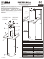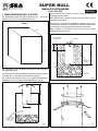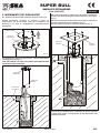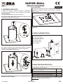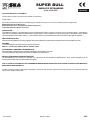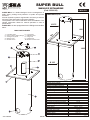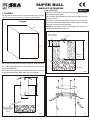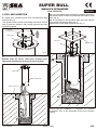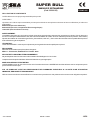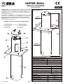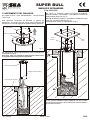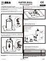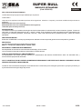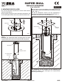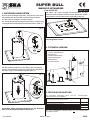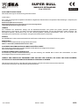
1
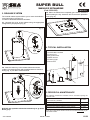
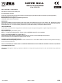
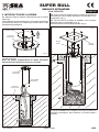
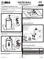
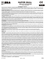
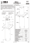
®
Sistemi Elettronici
di Apertura Porte e Cancelli
Italiano
English
International registered trademark n. 804888
SUPER BULL
(cod. 12500025)
cod. 67410706
REV 00 - 11/2009
Français
Español
Deutsch
®
SUPER BULL
Sistemi Elettronici
di Apertura Porte e Cancelli
MANUALE DI INSTALLAZIONE
International registered trademark n. 804888
(Cod.12500025)
SUPER BULL è un dissuasore per la gestione di aree di transito,
parcheggi e protezione di accessi pubblici e privati.
Costituito da un movimento idraulico realizzato negli stabilimenti
SEA per la massima silenziosità e affidabilità nel tempo.
La centralina idraulica è incorporata per una semplice
installazione. Il dispositivo di sblocco consente il movimento
manuale in caso di mancanza di energia elettrica.
SUPER BULL è dotato anche di indicatori luminosi a led (24V) e
avviso sonoro.
ITALIANO
DIMENSIONI (mm)
Ø 275
680
Piastra di fondazione
Foro passaggio cavi elettrici
Cilindro interrato
Chiusino carrabile
Colonna mobile
8
6
7
8
9
10
Segnalatori luminosi
Sistema di sblocco
Gancio di sollevamento
Centralina
Chiusino mobile
55
1
2
3
4
5
0
NOMENCLATURA PARTI PRINCIPALI
550
10
1600
7
6
5
Ø 325
4
9
1
CENTRALINA IDRAULICA
Portata pompa idraulica
Pressione d’esercizio media
Pressione massima regolazione
Temperatura d’esercizio
Olio idraulico
Grado di protezione
3
2
cod. 67410706
PISTONE OLEODINAMICO
Tempo di uscita stelo
Corsa utile stelo
Diametro stelo
Diametro stantuffo
Forza max di trazione in uscita stelo
Forza max di trazione in rientro stelo
Alimentazione luci ingombro (led)
MOTORE ELETTRICO
Alimentazione
Corrente assorbita
Potenza motore assorbita
Condensatore
Velocità rotazione
Frequenza di utilizzo
REV 00 - 11/2009
4 litri/min
2.2 MPA (22 bar)
4.5 MPA (45 bar)
-20°C +55°C
SEA
IP55
8 secondi
720 mm
16 mm
30 mm
275 Kg
147 Kg
24V
230Vac - 50 Hz
1,8 A
370 W
20 mF
2800 rpm
30%
2/28
®
SUPER BULL
Sistemi Elettronici
MANUALE DI INSTALLAZIONE
di Apertura Porte e Cancelli
International registered trademark n. 804888
ITALIANO
(Cod.12500025)
1.5. Inserire fra il tubo in PVC e la terra un tubo flessibile per il
passaggio dei cavi elettrici.
1. REALIZZAZIONE DELLO SCAVO
1.1. Realizzare in base alle misure riportate in Fig. 1 uno scavo
nel terreno dove si vuole installare il dissuasore.
1.6. Riempire tutto lo spazio fra la terra e il tubo in PVC con del
calcestruzzo tipo R425.
1.7. Prima che il calcestruzzo solidifichi, mettere il tubo in PVC
perfettamente verticale e la piastra di fondazione perfettamente
in orizzontale. Per questa operazione utilizzare una livella.
Scavo
N.B. La piastra di fondazione deve rimanere sotto il piano
stradale di 1 cm max. (Fig. 3).
110 cm
110 cm
Livella
32 cm
Tubo passaggio
cavi elettrici
130 cm
97 cm
Calcestruzzo
R425
Fig.1
1.2. Riempire lo scavo di pietre di circa 30 cm per favorire il
drenaggio dell’acqua.
1.3. Prevedere una guaina flessibile in plastica di almeno 40 mm
da far arrivare, ove possibile, alla conduttura fognante.
1.4. Inserire nello scavo un tubo in PVC (optional) dal diametro
esterno di almeno 40 cm e la piastra di fondazione. (Fig. 2)
Pietre
Fig.3
103 cm
(A)
40,5 cm
Tubo di scarico
acqua piovana
inserito in uno
dei fori A
Pietre
cod. 67410706
Fig.2
REV 00 - 11/2009
Fig.4
3/28
®
SUPER BULL
Sistemi Elettronici
di Apertura Porte e Cancelli
MANUALE DI INSTALLAZIONE
International registered trademark n. 804888
(Cod.12500025)
2. INSERIMENTO DEL DISSUASORE
2.1. Togliere il chiusino mobile svitando le tre viti come in Fig. 5.
Questa operazione consente di scoprire il gancio di
sollevamento che dovrà essere usato per l’inserimento del
dissuasore nel tubo di alloggiamento precedentemente
predisposto.
ITALIANO
2.3. Portare il dissuasore a battuta con la piastra di fondazione
avendo cura di lasciar adagiare sul fondo del tubo i cavi elettrici.
(Fig. 7)
2.4. Fissare il dissuasore alla piastra di fondazione mediante il
chiusino carrabile e le 4 viti in dotazione (Fig. 7).
Successivamente montare il coperchio superiore. (Fig. 7)
Fig. 7
Chiusino mobile
Gancio di
sollevamento
Coperchio
superiore
Chiusino
carrabile
Fig. 5
2.2. Utilizzando il gancio di sollevamento, inserire il dussuasore
nell’alloggiamento (Fig. 6).
N.B.: Far passare con cura i cavi elettrici nell’apposito tubo
senza accorciarli nè tenderli.
Fig. 6
Gancio di
sollevamento
Uscita cavi
elettrici
Alla centrale
di comando
A questo punto l’installazione è completata, per quanto riguarda
i collegamenti elettrici, fare riferimento al manuale relativo alla
centrale di comando.
cod. 67410706
REV 00 - 11/2009
4/28
®
Sistemi Elettronici
di Apertura Porte e Cancelli
International registered trademark n. 804888
SUPER BULL
MANUALE DI INSTALLAZIONE
ITALIANO
(Cod.12500025)
3. SISTEMA DI SBLOCCO
Il sistema di sblocco manuale consente di abbassare
manualmente il dissuasore in caso di emergenza o di assenza
di energia elettrica.
Per sbloccare il dissuasore operare come segue:
3.3. Quando il dissuasore è sceso completamente, ribloccare il
dissuasore ruotando la chiave in senso orario e riavvitare il
tappo (Fig. 10).
Fig. 10
3.1. Svitare il tappo dello sblocco utilizzando l’apposita chiave
esagonale fornita in dotazione (Fig. 8).
Fig. 8
N.B. Non lasciare il dissuasore abbassato con lo sblocco
disattivato.
4. INSTALLAZIONE TIPICA
1-Dissuasore BULL
2-Centrale di comando
3-Pulsante a chiave
4-Ricevitore radio
5-Lampeggiatore
6-Fotocellule
6
3.2. Inserire la stessa chiave nella fessura di sblocco e svitarla
(rotazione in senso antiorario) fino a quando il dissuasore
inizia a scendere dolcemente (Fig. 9).
6
5
4
3
6
2
1
Fig. 9
6
5. MANUTENZIONE PERIODICA
Le operazioni di manutenzione indicate di seguito possono essere
eseguite aprendo il chiusino mobile.
N.B. Questa operazione consente solo l’abbassamento del
dissuasore e non la risalita.
cod. 67410706
Controllare che il movimento del dissuasore sia sempre
lineare e senza impedimenti
Controllare il sistema di illuminazione (led)
Verificare la funzionalità dello sblocco
Verificare l’efficenza dei finecorsa (micro-switch)
Lubrificare gli steli guida con grasso idrorepellente
6 mesi
6 mesi
6 mesi
6 mesi
1-2 anni
Tutte le operazioni sopra descritte, devono essere eseguite
esclusivamente da un istallatore autorizzato.
REV 00 - 11/2009
5/28
®
Sistemi Elettronici
di Apertura Porte e Cancelli
International registered trademark n. 804888
SUPER BULL
MANUALE DI INSTALLAZIONE
(Cod.12500025)
ITALIANO
DICHIARAZIONE DI CONFORMITÁ
La SEA dichiara sotto la propria responsabilità che il prodotto
SUPER BULL
risponde ai requisiti essenziali previsti dalle seguenti direttive europee e successive modifiche (laddove applicabili):
89/392/CEE (Direttiva Macchine)
89/336/CEE (Direttiva Compatibilità Elettromagnetica)
73/23/CEE (Direttiva Bassa Tensione)
AVVERTENZE :
L'installazione elettrica e la scelta della logica di funzionamento devono essere in accordo con le normative vigenti. Prevedere in
ogni caso un interruttore differenziale da 16A e soglia 0,030A. Tenere separati i cavi di potenza (motori, alimentazioni) da quelli di
comando (pulsanti, fotocellule, radio ecc.). Per evitare interferenze è preferibile prevedere ed utilizzare due guaine separate.
DESTINAZIONE D'USO:
Il dissuasore SUPER BULL è stato progettato per essere utilizzato unicamente per la gestione di accessi pubblici e privati.
RICAMBI:
Le richieste per parti di ricambio devono pervenire presso:
SEA s.r.l. - Zona Ind.le, 64020 S.ATTO - Teramo - Italia
SICUREZZA E COMPATIBILITÀ AMBIENTALE:
Non disperdere nell'ambiente i materiali di imballaggio del prodotto e/o circuiti.
La movimentazione del prodotto deve essere eseguita con mezzi idonei.
MESSA FUORI SERVIZIO E MANUTENZIONE:
La disinstallazione e/o messa fuori servizio e/o manutenzione del dissuasore SUPER BULL deve essere eseguita solo ed
esclusivamente da personale autorizzato ed esperto.
N.B. IL COSTRUTTORE NON PUÒ CONSIDERARSI RESPONSABILE PER EVENTUALI DANNI CAUSATI DA USI IMPROPRI,
ERRONEI ED IRRAGIONEVOLI.
La SEA si riserva il diritto di apportare le modifiche o variazioni che ritenesse opportune ai propri prodotti e/o al presente manuale
senza alcun obbligo di preavviso.
cod. 67410706
REV 00 - 11/2009
6/28
®
SUPER BULL
Sistemi Elettronici
di Apertura Porte e Cancelli
MANUALE DI INSTALLAZIONE
International registered trademark n. 804888
(Cod.12500025)
SUPER BULL is a bollard designed for the management of
traffic areas, parkings and protection of public and private
accesses.
It has an hydraulic system is engineered in our factory to achieve
minimum noise and maximum long term reliability.
The hydraulic unit is self contained for ease of installation. The
release mechanism allows for manual operation in case of
power failure.
SUPER BULL is also equipped with 24V LED lights and audible
alarm.
ENGLISH
DIMENSIONS (mm)
Ø 275
680
Foundation plate
Hole for electric cables passage
Underground cylinder
Manhole cover
Movable column
8
6
7
8
9
10
Light signals
Release system
Lifting hook
Hydraulic unit
Movable manhole cover
55
1
2
3
4
5
0
MAIN PARTS NAMES
550
10
1600
7
6
5
Ø 325
4
9
1
HYDRAULIC UNIT
Hydraulic pump capacity
Medium working pressure
Maximum adjustment pressure
Working temperature
Hydraulic oil
Protection degree
3
HYDRAULIC PISTON
Exit time of the rod
Working stroke of the rod
Rod diameter
Piston diameter
Max tractive force during rod extension
Max tractive force during rod retraction
Obstruction light (led) power supply
2
cod. 67410706
ELECTRIC MOTOR
Power supply
Absorbed current
Absorbed motor power
Capacitor
Rotation speed
Frequency of use
REV 00 - 11/2009
4 liters/min
2.2 MPA (22 bar)
4.5 MPA (45 bar)
-20°C +55°C
SEA
IP55
6 seconds
720 mm
16 mm
30 mm
275 Kg
147 Kg
24V
230Vac - 50 Hz
1.8 A
370 W
20 mF
2800 rpm
30%
7/28
®
SUPER BULL
Sistemi Elettronici
di Apertura Porte e Cancelli
MANUALE DI INSTALLAZIONE
International registered trademark n. 804888
ENGLISH
(Cod.12500025)
1.5. Insert a flexible duct into the PVC pipe to allow for passage
of the electric supply cables.
1. DIGGING
1.1. Proceed with excavation using the measurements that you find in
Fig. 1 one. Dig in the ground where you intend to install the bollard
1.6. Fill all the space between ground and PVC pipe with high
strength concrete.
1.7. Before the concrete has fully set, make sure that the PVC
pipe is perfectly vertical and that the foundation plate in perfectly
horizontal. Use a level for this operation.
Digging
NOTICE: the foundation plate must be positioned 10 mm max
beneath finished floor level. (Fig. 3).
110 cm
110 cm
Level
32 cm
Tube for electric
cables passage
130 cm
97 cm
Concrete
R425
Fig.1
1.2. Fill the hole with stones for 30 cm to allow for water drainage.
1.3. Intall a plastic flexible Duct (40 mm diameter) to the mains
sewer pipe, if possible.
1.4. Insert a PVC (optional) pipe (external diameter min 40 mm)
in the hole and fit the foundation plate. (Fig. 2) 12710350
Stones
Fig.3
103 cm
(A)
40,5 cm
Discharge tube for
Rainwater inserted
in one of the
holes A
Stones
cod. 67410706
Fig.2
REV 00 - 11/2009
Fig.4
8/28
®
Sistemi Elettronici
SUPER BULL
di Apertura Porte e Cancelli
MANUALE DI INSTALLAZIONE
International registered trademark n. 804888
(Cod.12500025)
2. BOLLARD INSERTION
2.1. Remove the movable access cover unscrewing the three
screws as in Fig. 5.
This operation allows access to the lifting hook which must be
used to insert the bollard in the housing pipe that has been
previously prepared.
ENGLISH
2.3. Lower the bollard until it touches the foundation plate, taking
care that the electric cables are positioned at the bottom of the
tube (Fig. 7)
2.4. Fix the bollard to the foundation plate using the manhole
cover and the 4 screws provided (Fig. 7).
Afterward mount the upper manhole cover. (Fig. 7)
Fig. 7
Movable
manhole cover
Lifting hook
Top cover
Manhole cover
Fig. 5
2.2. Using the lifting hook, insert the bollard in the housing (Fig.
6).
NOTICE: make the electric cables pass carefully in the
appropriate pipe without shortening or stretching them.
Fig. 6
Lifting hook
Electric cables exit
To the control unit
At this point the installation is completed. For electrical
connections, refer to the appropriate control unit instruction
manual.
cod. 67410706
REV 00 - 11/2009
9/28
®
Sistemi Elettronici
di Apertura Porte e Cancelli
International registered trademark n. 804888
SUPER BULL
MANUALE DI INSTALLAZIONE
ENGLISH
(Cod.12500025)
3. RELEASE SYSTEM
The manual release system allows you to lower the bollard in
case of emergency or power cut.
In order to release the bollard act as follows:
3.3. When the bollard has completely gone down, relock the
bollard rotating the key clockwise and re-screw the protection
cover (Fig. 10).
Fig. 10
3.1. Unscrew the cover of the release using the appropriate
hexagonal key in equipment (Fig. 8).
Fig. 8
NOTICE: don’t leave the bollard down with the disabled lock.
4. TYPICAL INSTALLATION
1-SUPER BULL bollard
2-Control unit
3-Key pushbutton
4-Radio receiver
5-Flashing light
6-Photocells
6
3.2. Insert the same key in the release hole and unscrew
(rotate it counterclockwise) until the bollard starts to descend
slowly (Fig. 9). DO NOT OVER ROTATE.
6
5
4
3
6
2
1
Fig. 9
6
5. PERIODICAL MAINTENANCE
The following maintenance activities can be executed opening the
manhole cover.
NOTICE: this operation allows the bollard only to go down
Not to go up.
cod. 67410706
Check that the bollard movement is always linear and
doesn’t meet any obstacle.
Check the light system (led)
Check the release functionality
Check the limit switches efficiency (micro-switch)
Lubrificate the rods with water resistant grease
6 mnths
6 mnths
6 mnths
6 mnths
1-2 years
All the above described activities must be executed exclusively by an
authorized installer.
REV 00 - 11/2009
10/28
®
Sistemi Elettronici
di Apertura Porte e Cancelli
International registered trademark n. 804888
SUPER BULL
MANUALE DI INSTALLAZIONE
(Cod.12500025)
ENGLISH
DECLARATION OF CONFORMITY
SEA declares under its responsibility that
the SUPER BULL operator
meets all the essential requirements as provided by the following European laws and later modifications (where applicable):
89/392/CEE (Machines Directive)
89/336/CEE (Electromagnetic Compatibility Directive)
73/23/CEE (Low-tension Directive)
WARNINGS :
The electric installation and the functioning logic choice must agree with the laws in force. In all cases a 16A breaker with a 30mA
differential switch must be fitted. Keep the power cables (motors, power supply) separate from the command cables (push buttons,
photocells and so on). In order to avoid any interference it’s preferable to always use separate cables and ducts.
USE DESTINATION:
SUPER BULL bolalrd has been designed to be used exclusively as management equipment for public and private accesses.
REPLACEMENTS:
Any request for spare parts must be sent to:
SEA s.r.l. - Zona Ind.le, 64020 S.ATTO - Teramo - Italia or SEA UK Limited Tel: 0121 706 9629
SAFETY AND ENVIRONMENTAL COMPATIBILITY:
Please dispose of the packaging materials of products and / or circuits in an environmentally friendly manner.
Materials handling must be undertaken with appropriate vehicles.
DISINSTALLATION AND MAINTENANCE:
The disinstallation and/or putting out of service and/or maintenance of SUPER BULL bollard must be made only and exclusively by
authorized and qualified staff.
NOTICE: THE MANUFACTURER IS NOT CONSIDERED RESPONSIBLE FOR DAMAGE CAUSED BY IRREGULAR, WRONG
OR UNREASONABLE USE.
SEA reserves the right to make any required modification or change to the products and/or to this manual without any advanced
notification.
cod. 67410706
REV 00 - 11/2009
11/28
®
SUPER BULL
Sistemi Elettronici
di Apertura Porte e Cancelli
MANUALE DI INSTALLAZIONE
International registered trademark n. 804888
(Cod.12500025)
SUPER BULL est une borne pour la gestion des aires de transit,
de repos et pour la protection des accès publique et privés.
Avec mouvement hydraulique realisé dans les établissements
SEA pour le maxi. silence et plus haute fiabilité dans le temps.
Avec centrale hydraulique incorporée pour une simple
installation. Le dispositif de déverrouillage permet le
mouvement manuel en cas de coupure de courant
SUPER BULL est complet de led 24V indicateus lumineux et
avis sonore.
FRANCAIS
DIMENSIONS (mm)
Ø 275
680
Plaque de fondation
Trou passage cables ctr.
Cylindre sous sol
Tampon charretier
Colonne mobile
8
6
7
8
9
10
Avertisseur lumineux
Système de déverrouillage
Crochet de solèvement
Centrale
Tampon mobile
55
1
2
3
4
5
0
NOMENCLATURE COMPOSANTS PRINCIPEAUX
550
10
1600
7
6
5
Ø 325
4
9
1
CENTRALE HYDRAULIQUE
Débit pompe hydraulique
Pression d’exercice moyen
Pression max. réglage
Temperature d’exercice
Huile hydraulique
Degré de protection
3
PISTON HYDRAULIQUE
Temps sortie tige
Course utile tige
Diamètre tige
Diamètre piston
Force max de traction en sortie tige
Force max de traction en escamotage tige
Alimentation lampes signalation mouvement (led)
2
cod. 67410706
MOTEUR ELECTRIQUE
Alimentation
Courant absorbé
Puissance moteur absorbée
Condensateur
Vitesse rotation
Fréquence d’usage
REV 00 - 11/2009
4 litres/min
2.2 MPA (22 bar)
4.5 MPA (45 bar)
-20°C +55°C
SEA
Ip55
6 secondes
720 mm
16 mm
30 mm
275 Kg
147 Kg
24V
230Vac - 50 Hz
1.8 A
370 W
20 mF
2800 rpm
30%
12/28
®
SUPER BULL
Sistemi Elettronici
di Apertura Porte e Cancelli
MANUALE DI INSTALLAZIONE
International registered trademark n. 804888
FRANCAIS
(Cod.12500025)
1. REALISATION DU TRANCHEE
1.1. Réaliser, selon les mésures reportées dans Fig. 1, une
tranchée sur le sol là où on veut installer la borne.
Tranchee
1.5. Insérer entre le tube en PVC et le terrain un tube flexible
pour le passage des câbles électriques.
1.6. Remplir tout l’éspace entre le terrain et le tube en PVC avec
du béton du type R425.
1.7. Avant que le béton s’est solidifié, mettre le tube en PVC en
postion parfaitement verticale et la plaque de fondation en
position parfaitement horizontale. Utiliser une nivelle pour cette
opération.
Note: La plaque de fondation doit être positionnée de max. 1 cm
sous le niveau routier (Fig. 3).
110 cm
110 cm
Nivelle
32 cm
Tube passage
câble électrique
130 cm
97 cm
Béton
R425
Fig.1
1.2. Remplir la tranchée avec des pierres de 30 cm environ pour
favoriser le drainage de l’eau.
1.3. Prévoir une gaine flexible en plastique d’au moins 40mm et
faire la arriver, là où possible, à la canalisation des égouts.
1.4. Insérer dans la tranchée un tube en PVC (optional) avec un
diamètre extérieur d’au moins 40cm et la plaque de fondation
(Fig. 2)
Pierres
Fig.3
103 cm
(A)
40,5 cm
Tube de déversement
Eau de plue inséré en
un des trous A
Pietre
cod. 67410706
Fig.2
REV 00 - 11/2009
Fig.4
13/28
®
SUPER BULL
Sistemi Elettronici
di Apertura Porte e Cancelli
MANUALE DI INSTALLAZIONE
International registered trademark n. 804888
(Cod.12500025)
2. INTRODUCTION DE LA BORNE
2.1. Enlever le tampon mobile en dévissant les trois vis comme
dans Fig.5
Cette opération permet de découvrir le crochet de soulèvement
que devra être utilisé pour l’insertion de la borne dans le tube
précédemment prédisposé.
FRANCAIS
2.3. Porter la borne en feuillure avec la plaque de fondation et
faire attention que les câbles électriques sont étendues sur le
fond du tube. (Fig. 7)
2.4. Fixer la borne à la plaque de fondation avec le tampon
charretier et les 4 vis en dotation (Fig. 7).
Successivement monter le tampon mobile. (Fig. 7)
Fig. 7
Tampon mobile
Crochet de
soulèvement
Tampon
mobile
Tampon
charretier
Fig. 5
2.2. En utilisant le crochet de soulèvement, insèrer la borne dans
le logement (Fig. 6).
Note: Fair passer soigneusement les câbles électriques
dans le tube spécial sans les raccourcir ou tendre.
Fig. 6
Crochet de
soulèvement
Sortie câbles
électriques
A l’armoire
de commande
A ce point l’installation est complète, pour ce qui concerne les
connexions électriques, faire référence au manuel relatif à
l’armoire.
cod. 67410706
REV 00 - 11/2009
14/28
®
Sistemi Elettronici
di Apertura Porte e Cancelli
International registered trademark n. 804888
SUPER BULL
MANUALE DI INSTALLAZIONE
FRANCAIS
(Cod.12500025)
3. SYSTEME DE DEVERROUILLAGE
Le système de déverrouillage manuel permet de descendre
manuellement la borne en cas d’urgence ou d’absence de
courant électrique.
Pour déverrouiller la borne opérer comme suit:
3.3. Quand la borne est complètement descendu, rébloquer la
borne tournant la clef dans le sens des aiguilles d’une montre et
revisser le bouchon (Fig.10).
Fig. 10
3.1. Dévisser le bouchon du déverrouillage utilisant la clef
hexagonale spéciale en dotation (Fig.8).
Fig. 8
Note: Ne pas laisser la borne descendue avec le
déverrouillage disactivé.
4. INSTALLATION TYPE
1-Borne SUPER BULL
2-Armoire
3-Poussoir à clef
4-Récepteur radio
5-Clignoteur
6-Photocellule
3.2. Insérer la même clef dans la fissure du déverrouillage et
dévisser (tourner en sens inverse des aiguilles d’une montre)
jusqu’au moment que la borne commence à descendre
doucement (Fig. 9).
6
6
5
4
3
6
2
1
Fig. 9
6
5.ENTRETIEN PERIODIQUE
Les opérations d’entretien indiquées de suit peuvent être exécutées en
ouvrant le tampon mobile.
Note: Cette opération permet seulement l’abaissement de la
borne et pas le remontage.
cod. 67410706
Controller que le mouvement de la borne est toujours
linéaire et sans empêchements
Controller le système d’allumage (led)
Vérifier la fonction du déverrouillage
Vérifier l’efficacité des fins de course (micro-switch)
Lubrifier les tiges de guide avec du gras hydrofuge
6 mois
6 mois
6 mois
6 mois
1-2 ans
Toutes les opérations là- dessus doivent être exécutées exclusivement
par un installateur autorisé.
REV 00 - 11/2009
15/28
®
Sistemi Elettronici
SUPER BULL
di Apertura Porte e Cancelli
International registered trademark n. 804888
MANUALE DI INSTALLAZIONE
(Cod.12500025)
FRANCAIS
DECLARATION DE CONFORMITE
La SEA déclare sous sa propre responsabilité que le produit
SUPER BULL
répondent aux critères requis essentielles prévues par les directives européennes suivantes et leurs modifications (où elles sont
applicables):
89/392/CEE (Directive Machines)
89/336/CEE (Directive Compatibilité Electromagnétique)
73/23/CEE (Directive Basse Tension)
AVERTISSEMENT:
L'installation électrique et le choix de la logique de fonctionnement doivent respecter les normatives en vigueur. Prévoir dans tous
les cas un interrupteur différentiel de 16A, avec seuil de sensibilité de 0,030A. Tenir les câbles de protection (moteurs, alimentation)
séparés des câbles de commandes (poussoirs, photocellules, radio ecc.). Pour éviter des interférences il est préférable de prévoir
et de utiliser deux gaines séparées.
UTILISATION:
La borne SUPER BULL a été conçue uniquement pour la gestion des accèss publiques et privés.l
RECHANGES:
Adresser les demandes pour pièces de rechanges à:
SEA s.r.l. Zona Ind.le, 64020 S.ATTO - Teramo - Italia
SECURITE ET COMPATIBILITE ENVIRONNEMENT:
Ne pas disperser dans l'environnement les matériaux d'emballage et/ou les circuits.
Le déplacement du produit doit être effectué à l'aide des moyens appropriés.
MISE HORS SERVICE ET ENTRETIEN:
La désinstallation et/ou la mise hors service et/ou l'entretien de la borne SUPER BULLdoit être effectué seul et uniquement par le
personnel autorisé et expert.
N.B. LE FABRICANT N'EST PAS RESPONSABLE DES DOMMAGES EVENTUELS A LA SUITE D'UNE UTILISATION
IMPROPRE, ERRONNEE ET IRRAISONABLE.
SEA se réserve le droit de toute modification ou variation à ses produits et/ou à la présente notice sans aucune obligation de préavis.
cod. 67410706
REV 00 - 11/2009
16/28
®
SUPER BULL
Sistemi Elettronici
di Apertura Porte e Cancelli
MANUALE DI INSTALLAZIONE
International registered trademark n. 804888
(Cod.12500025)
SUPER BULL es un disuasor para la gestion de areas de
transito,parqueos y proteccion de accesos publicos y privados.
Constituido de un movimento hidraulico realizado en lo
establecimientos de SEA para la maxima sileciosidad y
afidabilidad en el tiempo.
La centralina hidraulica esta incorporada para una simple
instalacion. El dispositivo de desbloqueo consciente el
movimento manual en caso de ausencia de energia electrica..
SUPER BULL esta dotado tambien de indicadores luminosos
con led (24V) y avisos sonoros.
ESPAÑOL
DIMENSIONES (mm)
Ø 275
680
Placa de fundacion
Foro pasaje de cables electricos
Cilindro enterrado
Cierre de carril
Columna movil
8
6
7
8
9
10
Señales luminosos
Sistema de desbloqueo
Gancho de alzamiento
Centralina
Cierre movil
55
1
2
3
4
5
0
NOMENCLATURA DE LAS PARTES PRINCIPALES
550
10
1600
7
6
5
Ø 325
4
9
1
CENTRALINA HIDRAULICA
Capacidad de la bomba hidraulica
Presion del ejercicio en media
Presion maxima de regulacion
Temperatura de ejercicio
Aceite hidraulico
Grado de proteccion
3
PISTONE OLEODINAMICO
Tiempo de salida de la varilla
Carrera util de la varilla
Diametrovarilla
Diametro piston
Fuerza maxima de traccion de la salida de la varilla
Fuerza maxima de traccion de reentro de la varilla
Alimentacion luces engombro (led)
2
cod. 67410706
MOTOR ELECTRICO
Alimentacion
Corriente absorbida
Potencia absorvida
Condensador
Velocidad de rotacion
Frequencia utilizo
REV 00 - 11/2009
4 litros/min
2.2 MPA (22 bar)
4.5 MPA (45 bar)
-20°C +55°C
SEA
IP55
6 segundo
720 mm
16 mm
30 mm
275 Kg
147 Kg
24V
230Vac - 50 Hz
1,8 A
370 W
20 mF
2800 rpm
30%
17/28
®
SUPER BULL
Sistemi Elettronici
di Apertura Porte e Cancelli
MANUALE DI INSTALLAZIONE
International registered trademark n. 804888
ESPAÑOL
(Cod.12500025)
1.5. Inserir entre el tubo en PVC y la tierra un tubo flexible
para el pasaje de los cables electricos
1. REALIZACION DE LA EXCAVACION
1.1. Realizar en base a las medidas reportadas en Fig.1 una
excavacion en el terreno donde se quiere instalar el disuasor.
1.6. Llenar todo el espacion entre la tierra y el tubo de pvc con
concreto tipo R425.
1.7. Antes que el concreto solidifique, colocar el tubo en PVC
perfectamente vertical a la placa de fundacion perfectamente
en horizontal . Para esta operacion utilizar un nivel.
N.B. La placa de fundacion debe quedar debajo el plano de la
calle de 1 cm max. (Fig. 3).
Excavacion
110 cm
110 cm
Nivel
32 cm
Tubo pasaje
cables electricos
130 cm
97 cm
Concreto
R425
Fig.1
1.2. Llenar la excavacion de piedras alrededor de 30 cm para
favorecer el drenaje del agua.
1.3. Preveder una guaina flexible en plastica de almenos 40 mm
da para hacer llegar , donde es posible, al conducto de la cloaca.
1.4. Insertar en la excavacion un tubo en PVC (opcional) del
diametro externo de almenos 40 cm y la placa de fundacion .
(Fig. 2)
Piedras
Fig.3
103 cm
(A)
40,5 cm
Tubo de descarga
agua de lluvia
insertado en uno de
los agujeros A
Piedras
cod. 67410706
Fig.2
REV 00 - 11/2009
Fig.4
18/28
®
SUPER BULL
Sistemi Elettronici
di Apertura Porte e Cancelli
MANUALE DI INSTALLAZIONE
International registered trademark n. 804888
(Cod.12500025)
2. INSERIMENTO DEL DISUASOR
2.1. Quitar el cierre movil desatornillando
como Fig. 5.
los tres tornillos
Esta operacion consciente de descubrir el gancho de
alzamiento que tendra que ser usado para la insercion del
disuasor en el tubo de alojamiento precedemente predisposto..
ESPAÑOL
2.3. Llevar el disuasor a golpe con la placa de fundacion
teniendo cuidado cura de dejar acomodado en el fondo del
tubolos cables electricos. (Fig. 7)
2.4. Fijar el disuasor a la placa de fundacion mediante el cierre
carril y los 4 tornillo en dotacion (Fig. 7).
Sucesivamente montar la tapa superior. (Fig. 7)
Fig. 7
Cierre movil
Gancho de alzamiento
Tapa
superior
Cierre
carril
Fig. 5
2.2. Utilizando el gancho de alzamiento, inserir el dusuasor en
el alojamiento (Fig. 6).
N.B.: Hacer pasar con cuidado los cables electricos electricos en
el apropiado tubo sin recortarlos o extenderlos.
Fig. 6
Gancho de alzamiento
Salida de cables electricos
A la central de comando
A este punto la instalacion esta completada, a lo que se refiere
las conexiones electricas, hacer referimiento manual relativo a
la central de comando.
cod. 67410706
REV 00 - 11/2009
19/28
®
Sistemi Elettronici
di Apertura Porte e Cancelli
International registered trademark n. 804888
SUPER BULL
MANUALE DI INSTALLAZIONE
ESPAÑOL
(Cod.12500025)
3.SISTEMA DE DESBLOQUEO
El sistema de desbloqueo manual consciente debajar
manualmente el disuasor en caso de emergencia o deausencia
de energia electrica.
Para desbloquear el disuasor operar como sigue:
3.3. Cuando el disuasor ha bajado completamente,volver ha
bloquear el disuasor rotando la llave en sentido horarioy volver a
atornillar la tapa (Fig. 10).
Fig. 10
3.1. Desatornillar la tapa del desblòqueo utilizandola apropiada
llave hexagonal proveida en dotacion (Fig. 8).
Fig. 8
N.B. No dejar el disuasor bajado con el desbloqueo
desactivado
4. INSTALACION TIPICA
1-Disuasor SUPER BULL
2-Central de mando
3-Selector de llave
4-Receptor de radio
5-Lampara
6-Fotocelula
6
3.2. Inserir la misma llave de desbloqueo y desatornillarla
(rotacion en sentido antihorario) hasta cuando el disuasor inicia
a bajar suavemente (Fig. 9).
6
5
4
3
6
2
1
Fig. 9
6
5. MANTENIMIENTO PERIODICO
Las operaciones de mantenimiento indicadas a continuacion pueden
ser efectuadas abriendo el cierre movil.
N.B. Esta operacion consciente solo el bajar el disuasor y
no la subida.
cod. 67410706
Controlar que el movimiento del disuasor sea siempre
lineal o sin impedimentos
Controlar el sistema de iluminacion (led)
Verificar la funcionabilidad del desbloqueo
Verficar la eficiencia del final de carrera (micro-switch)
Lubrificar las varrilas guia con grasa idropelente.
6 meses
6 meses
6 meses
6 meses
1-2 años
Todas las operaciones arriba descritas, deben ser efectuadas
exclusivamente por un instalador autorizado.
REV 00 - 11/2009
20/28
®
Sistemi Elettronici
di Apertura Porte e Cancelli
International registered trademark n. 804888
SUPER BULL
MANUALE DI INSTALLAZIONE
(Cod.12500025)
ESPAÑOL
DECLARACION DE CONFORMIDAD
La SEA declara bajo la propria responsabilidad que el producto
SUPER BULL
responde a los requisitos esenciales previstos de las siguientes directivas europeas y sucesivas modificaciones(en donde se
aplicable):
89/392/CEE (Directiva de maquinas)
89/336/CEE (Directiva de compatibilidad electromagnetica)
73/23/CEE (Directiva Baja Tension)
ADVERTENCIAS :
La instalacion electrica y la sellecion de la logica de funcionamiento deben ser deacuerdo con las normativas vigentes. Preveer en
cada caso un interruptor diferencial de 16A y umbral 0,030A. Tener seprados los cables de potencia (motor, alimentacion) de
auquellos de comando (pulsantes, fotocelulas, radio etc.). Para evitar interferencias es preferible preveer y utilizar dos fundas
separadas.
DESTINACION DE USO:
El disuasor SUPER BULL ha sido proyectado para ser utilizado unicamente para la gestion de accesos publicos y privados.
REPUESTOS:
La demanda de la piezas de recambio debe proceder de :
SEA s.r.l. - Zona Ind.le, 64020 S.ATTO - Teramo - Italia
SEGURIDAD Y COMPATIBILIDAD AMBIENTAL:
No desperdiciar en el ambiente los materiales de embalaje y /o los circuitos.
La movimentacion del producto debe ser efectuada con medios idoneos.
PUESTA FUERA DE SERVICIO Y MANTENIMIENTO:
La desinstalacion y/o puesta fuera de servicio y/o mantenimiento del disuasor SUPER BULL debe ser efectuada solo y
exclusivamente por personal autorizado.
N.B. EL CONSTRUCTOR NO PUEDE CONSIDERARSE REPONSABLE POR EVENTUALES DAñOS CAUSADOS POS USO
INPROPIO, ERRONEO O IRRACIONALES.
La SEA se reserva el derecho de aportar las modificaciones o variaciones que se retengan oportunas a los proprios productos y/o
al presente manual sin algun obligo de preaviso.
cod. 67410706
REV 00 - 11/2009
21/28
®
SUPER BULL
Sistemi Elettronici
di Apertura Porte e Cancelli
MANUALE DI INSTALLAZIONE
International registered trademark n. 804888
(Cod.12500025)
SUPER BULL ist ein Poller, der zur Absperrung von
Transitzonen und Parkplätzen und zum Schutz von öffentlichen
und privaten Einfahrten dient. BULL wurde vollstaendig in den
SEA Werken hergestellt und ist aufgrund seines hydraulischen
Bewegungsablaufs
geraeuscharm und langrfristig
zuverlaessig.
Mit eingebauter hydraulischer Steueurng für eine einfache
Installierung. Die Entriegelung ermöglicht den manuellen
Betrieb im Falle von Stromausfall oder Notfällen.
SUPER BULL ist mit Licht (24V led)-und akustischem Melder
ausgestattet.
DEUTSCH
MASSE (mm)
Ø 275
680
Grundplatte
Durchlass elektr. Kabel
Unterirdischer Zylinder
Befahrbare Flansch
Beweglicher Zylinder
8
6
7
8
9
10
Lichtanzeige
Entriegelung
Hebevorrichtung
Hydraulische Steuerung
Mobile Flansch
55
1
2
3
4
5
0
NOMENKLATUR HAUPTBESTANDTEILE
550
10
1600
7
6
5
Ø 325
4
9
1
HYDRAULISCHE STEUERUNG
Hydraulische Pumpenleistung
Druck bei Durchschnittsbetrieb
Druck bei höchster Einstellung
Betriebstemperatur
Hydraulisches Öl
Schutzgrad
3
2
cod. 67410706
HYDRAULISCHER KOLBEN
Stangenausfahrzeit
Stangennutzlauf
Stangendurchmesser
Kolbendurchmesser
Max. Zugkraft Stangenausfahrt
Max. Zugkraft Stangeneifahrt
Speisung Bwegung Signallampe (led)
ELEKTRISCHER MOTOR
Speisung
Stromverbrauch
Motorstärke
Kondensator
Drehgeschwindigkeit
Betriebsfrequenz
REV 00 - 11/2009
4 Liter/Min
2.2 MPA (22 bar)
4.5 MPA (45 bar)
-20°C +55°C
SEA
IP55
6 Sekunden
720 mm
16 mm
30 mm
275 Kg
147 Kg
24V
230Vac - 50 Hz
1.8 A
370 W
20 mF
2800 rpm
30%
22/28
®
SUPER BULL
Sistemi Elettronici
di Apertura Porte e Cancelli
MANUALE DI INSTALLAZIONE
International registered trademark n. 804888
DEUTSCH
(Cod.12500025)
1. AUSHEBEN DES GRABENS
1.1. Einen Graben an der Stelle, wo man den Poller montieren
möchte, ausheben. Masse siehe Abb. 1
Graben
1.5. Zwischen dem PVC Rohr und dem Boden eine flexible
Hülse für den Durchlass der elektrischen Kabel legen.
1.6. Den gesamten Zwischenraum zwischen Erde und PVC
Rohr mit Beton Typ R425 auffüllen.
1.7. Bevor der Beton erhärtet, das PVC Rohr perfekt vertikal und
die Grundplatte perfekt horizontal installieren. Wasserwaage
verwenden.
110 cm
N.B. Die Grundplatte muss max. 1 cm (Abb.3) unter der
Strassenebene platziert sein.
110 cm
Wasserwaage
32 cm
Durchlasshülse
elektrische Kabel
130 cm
97 cm
Beton
R425
Abb.1
1.2. Den Graben mit ca. 30cm grossen Steinen auffüllen, um die
Wasserdränung zu fördern.
1.3. Eine flexible Plastikhülse von mind. 40mm, dort wo möglich,
vorsehen und zum Abwasserkanal führen.
1.4. Ein PVC Rohr mit mindestens 40 cm Aussendurchmesser
(optional) und die Grundplatte in den Graben (Abb.2) einsetzten.
Steine
Abb.3
103 cm
(A)
40,5 cm
Regenwasser
Abflussrohr
das in eine der
Bohrungen A
eingefuehrt ist
Steine
cod. 67410706
Abb.2
REV 00 - 11/2009
Abb.4
23/28
®
SUPER BULL
Sistemi Elettronici
di Apertura Porte e Cancelli
MANUALE DI INSTALLAZIONE
International registered trademark n. 804888
(Cod.12500025)
2. MONTAGE DES POLLERS
2.1. Die drei Schrauben abschrauben und die mobile Flansch
entfernen (siehe Abb. 5)
Dieser Vorgang ermöglicht es den Hebehaken abzudecken, der
zur Einführung des Pollers in das zuvor positionierte Rohr dient.
DEUTSCH
2.3. Den Poller mit der Grundplatte zum Anschlag bringen und
darauf achten, dass auf dem Rohrboden die elektrischen Kabel
liegen. (Abb. 7)
2.4. Mit der befahrbaren Flansch und den mitgelieferten 4
Schrauben den Poller an der Grundplatte befestigen (Abb. 7).
Danach die mobile Flansch montieren (Abb. 7)
Abb. 7
Mobile Flansch
Hebehaken
Mobile Flansch
Befahrbare
Flansch
Abb. 5
2.2. Mit Hilfe des Hebehakens den Poller in seine Position einführen
(Abb. 6).
ACHTUNG: Die elektrischen Kabel vorsichtig durch die dafür
vorgesehe Hülse ziehen ohne sie zu verkürzen oder zu spannen.
Abb. 6
Hebehaken
Austritt
elektrische Kabel
Zur elektronischen
Steuerung
Die Installierung ist nun beendet. Für die Verbindung der
elektrischen Kabel in den Anleitungen der entsprechenden
Steuerung nachschlagen.
cod. 67410706
REV 00 - 11/2009
24/28
®
Sistemi Elettronici
di Apertura Porte e Cancelli
International registered trademark n. 804888
SUPER BULL
MANUALE DI INSTALLAZIONE
DEUTSCH
(Cod.12500025)
3. ENTRIEGELUNGSSYSTEM
Das manuelle Entriegelungssystem ermöglicht es den Poller
bei Notfällen oder Stromausfall manuell herunterzulassen.
Um den Poller zu entriegeln, wie folgt vorgehen:
3.3. Wenn der Poller komplett heruntergefahren ist, den
Schlüssel im Uhrzeigersinn drehen und den Verschluss wieder
festschrauben um den Poller erneut zu blockieren (Abb.10).
Abb. 10
3.1. Den Entriegelungsverschluss mit dem dafür vorgesehenen
und mitgelieferten Seckskantschlüssel abschrauben. (Abb. 8).
Abb. 8
ACHTUNG: Den Poller nicht mit disaktivierter Entriegelung
heruntergefahren lassen.
4. TYPINSTALLIERUNG
1-Poller SUPER BULL
2-Steuerung
3-Schluesselschalter
4-Funkempfaenger
5-Blinklampe
6-Lichtschranke
6
3.2. Den gleichen Schlüssel in die Öffnung der Entriegelung
stecken und schrauben (gegen den Uhrzeigersinn drehen) bis
der Poller beginnt sanft herunterzugleiten (Abb. 9).
6
5
4
3
6
2
1
Abb. 9
6
5. PERIODISCHE WARTUNG
Die bewegliche Abdeckung öffnen und die
Wartungsarbeiten druchgeführen.
Den Bewegungsablauf des Pollers überprüfen und sicherstellen, dass
dieser immer gerade und Störungsfrei verläuft.
6 monate
Beleuchtungssystem überprüfen (led)
6 monate
6 monate
6 monate
1-2 jahre
Die Entriegelungsfunktion überprüfen
Die Leistungsfähigkeit der Endschalter überprüfen (micro-switch)
ACHTUNG: Dieser Vorgang ermöglicht nur das Absenken
aber nicht das Wiederhochfahren des Pollers.
cod. 67410706
nachfolgenden
Die Schaftführung mit wasserabweisendem Fett abschmieren
Die oben beschriebenen Arbeiten dürfen nur von Fachpersonal
durchgeführt werden.
REV 00 - 11/2009
25/28
®
Sistemi Elettronici
di Apertura Porte e Cancelli
International registered trademark n. 804888
SUPER BULL
MANUALE DI INSTALLAZIONE
(Cod.12500025)
DEUTSCH
KONFORMITÄTSERKLÄRUNG
SEA erklärt unter eigener Verantwortung, dass das Produkt
SUPER BULL
den, in den nachfolgenden europäischen Richtlinien aufgeführten Erfordernissen und späteren Überarbeitungen entspricht (dort
wo anwendbar):
89/392/CEE (Maschinenrichtlinie)
89/336/CEE (Richtlinie zur elektromechanischen Verträglichkeit)
73/23/CEE (Niederspannungsrichtlinie)
HINWEIS
Die Installation der elektrischen Anlage und die Betriebsart-Auswahl sind gemäß den jeweils geltenden gesetzlichen
Bestimmungen vorzunehmen. Auf jeden Fall einen Differential-Schutzschalter 16A und Schwellenwert 0,030A einsetzen. Die
Stromkabel (Motoren, Stromzufuhr) sind von den Steuerungskabeln (Schalter,Lichtschranken, Funk, etc.) zu trennen. Zur
Vermeidung von Interferenzen, ist es ratsam, zwei getrennte Isolierhülsen zu verwenden.
EINSATZ
Der SUPER BULL Poller wurde ausschließlich für den Einsatz auf öffentlichen und privaten Einfahrten geplant.
ERSATZTEILE
Anfragen nach Ersatzteilen bitte an folgende Adresse richten:
SEA s.r.l. Zona Ind.le, 64020 S.ATTO Teramo - Italia
SICHERHEITSBESTIMMUNGEN UND UMWELTVERTRÄGLICHKEIT
Das Verpackungsmaterial des Produkts und/oder der Schaltkreise umweltgerecht entsorgen.
Das Produkt artgerecht transportieren.
AUßERBETRIEBSETZUNG UND WARTUNG
Die Entfernung und/oder Außerbetriebsetzung und oder Wartung des SUPER BULL Pollers darf auschließlich von dazu
berechtigtem Fachpersonal durchgeführt werden.
HINWEIS: DER HERSTELLER ÜBERNIMMT KEINE HAFTUNG FÜR SCHÄDEN, DIE DURCH EINE UNSACHGEMÄßE,
FEHLERHAFTE UND UNGEEIGNETE VERWENDUNG VERURSACHT WURDEN.
SEA räumt sich das Recht ein, ohne Benachrichtigungspflicht, die für ihre Produkte und/oder dieses Hanbuch
erforderlichen Änderugen oder Überarbeitungen durchzuführen.
cod. 67410706
REV 00 - 11/2009
26/28
®
Sistemi Elettronici
di Apertura Porte e Cancelli
International registered trademark n. 804888
SUPER BULL
MANUALE DI INSTALLAZIONE
(Cod.12500025)
ITALIANO
CONDIZIONI DI VENDITA
EFFICACIA DELLE PRESENTI CONDIZIONI GENERALI DI VENDITA: Le presenti condizioni generali di vendita si applicano a tutti gli ordini
indirizzati a SEA s.r.l. Tutte le vendite fatte da SEA ai clienti sono regolate secondo le presenti condizioni di vendita che costituiscono parte
integrante del contratto di vendita ed annullano ogni clausola contraria o pattuizioni particolari presenti nell’ ordine o in altro documento
proveniente dall’ acquirente (cliente)
AVVERTENZE GENERALI Gli impianti di automazioni porte e cancelli vanno realizzati esclusivamente con componenti SEA, salvo accordi
specifici. L’inosservanza delle norme di sicurezza vigenti (Norm. EUROPEE EN 12453 - EN 12445 e altro) e di buona tecnica esclude la SEA da
ogni responsabilità. La SEA non risponde del mancato rispetto della corretta e sicura installazione secondo le norme.
1) PROPOSTA D’ORDINE La proposta d’ordine si intenderà accettata solo dopo la sua approvazione da parte della SEA. Conseguenza della sua
sottoscrizione, l’acquirente sarà vincolato alla stipula di un contratto d’acquisto, secondo quanto contenuto nella stessa proposta d’ordine e nelle
presenti condizioni di vendita. Viceversa, la mancata comunicazione all’acquirentedell’aprovazione della proposta d’ordine, non comporta la sua
automatica accettazione da parte della SEA
2) VALIDITÀ OFFERTA Le offerte proposte dalla SEA o dalla sua struttura commerciale periferica, avranno una validità di 30 giorni solari, salvo
diversa comunicazione in merito.
3) PREZZI I prezzi della proposta d’ordine sono quelli del listino in vigore alla data della redazione della stessa. Gli sconti applicati dalla struttura
commerciale periferica della SEA si intenderanno validi solo dopo la loro accettazione da parte della SEA. I prezzi si intendono per merce resa
franco ns. stabilimento in Teramo, esclusi IVA ed imballaggi speciali. La SEA si riserva il diritto di modificare in qualsiasi momento il listino, dando
opportuno preavviso alla rete di vendita. Le condizioni speciali riservate agli acquisti con formula agevolata Qx, Qx1, Qx2, Qx3 sono riservate ai
distributori ufficiali dietro accettazione scritta da parte della direzione SEA.
4) PAGAMENTI Le forme di pagamento ammesse sono quelle comunicate o accettate di volta in volta dalla SEA. Il tasso di interesse sul ritardo da
pagamento è del 1,5% mensile e comunque non oltre il tasso massimo legalmente consentito.
5) CONSEGNA La consegna avverrà indicativamente ma non tassativamente entro 30 giorni lavorativi dalla data di ricezione dell’ordine, salvo
diverse comunicazioni in merito. Il trasporto degli articoli venduti sarà effettuato a spese ed a rischio dell’acquirente. La SEA si libera dall’obbligo
della consegna rimettendo la merce al vettore, sia esso scelto dalla SEA oppure dall’acquirente. Eventuali smarrimenti e/o danneggiamenti della
merce dovuti al trasporto, sono a carico dell’acquirente.
6) RECLAMI Eventuali reclami e/o contestazioni dovranno pervenire alla SEA entro 8 giorni solari dalla ricezione della merce, supportati da idonei
documenti provanti la loro veridicità.
7) FORNITURA L’ordine in oggetto viene assunto da SEA senza alcun impegno e subordinatamente alle possibilità di approvvigionamento delle
materie prime occorrenti alla produzione; eventuali mancate esecuzioni totali o parziali non possono dar luogo a reclami e riserve per danni. La
fornitura SEA è strettamente limitata alla sola merce di sua produzione, esclusi il montaggio, l’installazione ed il collaudo. La SEA declina pertanto
ogni responsabilità per danni che dovessero derivare, anche a terzi, dall’inosservanza delle norme di sicurezza e della buona regola d’arte nelle
fasi dell’installazione e dell’impiego dei prodotti venduti.
8) GARANZIA La garanzia minima è di 12 mesi e può essere estesa, come di seguito, in caso di riconsegna del certificato di garanzia.
SILVER: Le parti meccaniche degli operatori rientranti in tale categoria sono garantite per 24 mesi dalla data di fabbricazione riportata
sull’operatore.
GOLD: Le parti meccaniche degli operatori rientranti in tale categoria sono garantite per 36 mesi dalla data di fabbricazione riportata
sull’operatore.
PLATINUM: Le parti meccaniche degli operatori rientranti in tale categoria sono garantite per 36 mesi dalla data di fabbricazione riportata
sull’operatore. La garanzia di base (36 mesi) sarà estesa per ulteriori 24 mesi (fino ad un totale di 60 mesi) qualora venga acquistato il certificato di
garanzie che dovrà essere compilato e rispedito alla SEA s.r.l. entro 60 giorni dall’acquisto. L’elettronica e le centrali di comando sono garantite
per 24 mesi dalla data di fabbricazione. Nell’eventualità di difettosità del prodotto, la SEA si impegna alla sua sostituzione gratuita oppure alla sua
riparazione, previa restituzione al proprio centro di riparazione. La definizione di stato di garanzia è ad insindacabile giudizio della SEA. I pezzi
sostitutivi restano di proprietà della SEA. In modo vincolante, il materiale dell’acquirente ritenuto in garanzia deve essere spedito al centro di
riparazione della SEA in porto franco e sarà rispedito dalla SEA in porto assegnato. La garanzia non si estende alla manodopera eventualmente
accorsa. I difetti riconosciuti non produrranno alcuna responsabilità e/o richiesta di danni, di qualsiasi natura essi siano, da parte dell’acquirente
nei riguardi della SEA. La garanzia non è in ogni caso riconosciuta qualora sia stata apportata alla merce qualsivoglia modifica, oppure vi sia stato
un uso improprio, oppure si sia in presenza di una qualsivoglia sua manomissione o di un montaggio non corretto, oppure se sia stata rimossa
l’etichetta apposta dal produttore comprensiva del marchio SEA registrato n° 804888. La garanzia non è inoltre valida nel caso la merce SEA sia
stata in parte o in toto accoppiata a componenti meccanici e/o elettronici non originali, ed in particolare in assenza di una specifica autorizzazione
in merito, ed inoltre nel caso in cui l’acquirente non sia in regola con i pagamenti. La garanzia non comprende danni derivati dal trasporto,
materiale di consumo, avarie dovute al mancato rispetto delle specifiche prestazionali dei prodotti indicate nel listino. Non è riconosciuto alcun
indennizzo durante il tempo di riparazione e/o sostituzione della merce in garanzia. La SEA declina ogni responsabilità per danni a cose o persone
derivanti dall’inosservanza delle norme di sicurezza e della non conforme installazione o dall’impiego errato dei prodotti venduti. La riparazione
dei prodotti in garanzia e fuori garanzia è subordinata al rispetto delle procedure comunicate da SEA.
9) RISERVATO DOMINIO Sulla merce venduta è valida la clausola del riservato dominio, della quale la SEA deciderà autonomamente se
avvalersi o meno, in virtù della quale l’acquirente acquisisce la proprietà della merce, solo dopo che il suo pagamento sia stato completamente
effettuato.
10) FORO COMPETENTE Per qualsiasi controversia avente per oggetto l’applicazione di questo contratto, viene eletto competente il Foro di
Teramo. La lingua valida nell’ interpretazione di cataloghi, manuali di installazione, condizioni di vendita o altro è quella italiana. La SEA si riserva la
facoltà di apportare modifiche tecniche atte a migliorare i propri prodotti, presenti o meno in questo Listino, in qualsiasi momento senza preavviso.
La SEA declina ogni responsabilità derivante da possibili inesattezze contenute nel presente listino, derivanti da errori di stampa e/o trascrizione. Il
presente Listino annulla e sostituisce quelli precedenti. L’acquirente ai sensi della legge 196/2003 (codice privacy) acconsente all’inserimento dei
propri dati personali derivanti dal presente contratto negli archivi informatici e cartacei della SEA s.r.l. al loro trattamento per motivi commerciali ed
amministrativi.
Diritti di proprietà industriale: il cliente, con l’acquisto, accetta le presenti condizioni di vendita e riconosce in capo a SEA la titolarità esclusiva
del marchio internazionale SEA registrato n. 804888 apposto sulle etichette dei prodotti e/o sui manuali e/o su ogni altra documentazione, e si
impegna ad utilizzare il medesimo nella propria attività di rivendita e/o installazione secondo modalità che non ne riducano in alcun modo i diritti, a
non rimuovere, sostituire o alterare marchi o altri segni distintivi di qualsiasi genere apposti ai prodotti.
E’ vietata ogni forma di riproduzione o utilizzo del marchio SEA e di ogni altro segno distintivo presente sui prodotti, salvo autorizzazione scritta di
SEA srl.
Agli effetti dell’articolo 1341 del C.C. si approvano specificatamente per iscritto le clausole di cui ai numeri:
4) PAGAMENTI - 8) GARANZIA - 10) FORO COMPETENTE
cod. 67410706
REV 00 - 11/2009
27/28
®
Sistemi Elettronici
di Apertura Porte e Cancelli
International registered trademark n. 804888
SUPER BULL
MANUALE DI INSTALLAZIONE
(Cod.12500025)
ENGLISH
TERMS OF SALES
EFFICACY OF THE FOLLOWING TERMS OF SALE: the following general terms of sale shall be applied to all orders sent to SEA srl.
All sales made by SEA to all costumers are made under the prescription of this terms of sales which are integral part of sale contract
and cancel and substitute all apposed clauses or specific negotiations present in order document received from the buyer.
GENERAL NOTICE The systems must be assembled exclusively with SEA components, unless specific agreements apply. Noncompliance with the applicable safety standards (European Standards EM12453 – EM 12445) and with good installation practice
releases SEA from any responsibilities. SEA shall not be held responsible for any failure to execute a correct and safe installation under
the above mentioned standards.
1) PROPOSED ORDER The proposed order shall be accepted only prior SEA approval of it. By signing the proposed order, the Buyer
shall be bound to enter a purchase agreement, according to the specifications stated in the proposed order.
On the other hand, failure to notify the Buyer of said approval must not be construed as automatic acceptance on the part of SEA.
2) PERIOD OF THE OFFER The offer proposed by SEA or by its branch sales department shall be valid for 30 solar days, unless
otherwise notified.
3) PRICING The prices in the proposed order are quoted from the Price List which is valid on the date the order was issued. The
discounts granted by the branch sales department of SEA shall apply only prior to acceptance on the part of SEA. The prices are for
merchandise delivered ex-works from the SEA establishment in Teramo, not including VAT and special packaging. SEA reserves the
right to change at any time this price list, providing timely notice to the sales network. The special sales conditions with extra discount
on quantity basis (Qx, Qx1, Qx2, Qx3 formula) is reserved to official distributors under SEA management written agreement.
4) PAYMENTS The accepted forms of payment are each time notified or approved by SEA. The interest rate on delay in payment shall
be 1.5% every month but anyway shall not be higher than the max. interest rate legally permitted.
5) DELIVERY Delivery shall take place, approximately and not peremptorily, within 30 working days from the date of receipt of the
order, unless otherwise notified. Transport of the goods sold shall be at Buyer’s cost and risk. SEA shall not bear the costs of delivery
giving the goods to the carrier, as chosen either by SEA or by the Buyer. Any loss and/or damage of the goods during transport, are at
Buyer’s cost.
6) COMPLAINTS Any complaints and/or claims shall be sent to SEA within 8 solar days from receipt of the goods, proved by adequate
supporting documents as to their truthfulness.
7) SUPPLY The concerning order will be accepted by SEA without any engagement and subordinately to the possibility to get it’s
supplies of raw material which is necessary for the production; Eventual completely or partially unsuccessful executions cannot be
reason for complains or reservations for damage. SEA supply is strictly limited to the goods of its manufacturing, not including
assembly, installation and testing. SEA, therefore, disclaims any responsibility for damage deriving, also to third parties, from noncompliance of safety standards and good practice during installation and use of the purchased products.
8) WARRANTY The standard warranty period is 12 months. This warranty time can be extended by means of expedition of the
warranty coupon as follows:
SILVER: The mechanical components of the operators belonging to this line are guaranteed for 24 months from the date of
manufacturing written on the operator.
GOLD: The mechanical components of the operators belonging to this line are guaranteed for 36 months from the date of
manufacturing written on the operator.
PLATINUM: The mechanical components of the operators belonging to this line are guaranteed for 36 months from the date of
manufacturing written on the operator. The base warranty (36 months) will be extended for further 24 months (up to a total of 60
months) when it is acquired the certificate of warranty which will be filled in and sent to SEA s.r.l. The electronic devices and the
systems of command are guaranteed for 24 months from the date of manufacturing. In case of defective product, SEA undertakes to
replace free of charge or to repair the goods provided that they are returned to SEA repair centre. The definition of warranty status is by
unquestionable assessment of SEA. The replaced parts shall remain propriety of SEA. Binding upon the parties, the material held in
warranty by the Buyer, must be sent back to SEA repair centre with fees prepaid, and shall be dispatched by SEA with carriage forward.
The warranty shall not cover any required labour activities.
The recognized defects, whatever their nature, shall not produce any responsibility and/or damage claim on the part of the Buyer
against SEA. The guarantee is in no case recognized if changes are made to the goods, or in the case of improper use, or in the case of
tampering or improper assembly. Furthermore, the warranty shall not apply if SEA products are partly or completely coupled with nonoriginal mechanical and/or electronic components, and in particular, without a specific relevant authorization, and if the Buyer is not
making regular payments. The warranty shall not cover damage caused by transport, expendable material, faults due to nonconformity with performance specifications of the products shown in the price list. No indemnification is granted during repairing and/or
replacing of the goods in warranty. SEA disclaims any responsibility for damage to objects and persons deriving from non-compliance
with safety standards, installation instructions or use of sold goods.
9) RESERVED DOMAIN A clause of reserved domain applies to the sold goods; SEA shall decide autonomously whether to make use
of it or not, whereby the Buyer purchases propriety of the goods only after full payment of the latter.
10) COMPETENT COURT OF LAW In case of disputes arising from the application of the agreement, the competent court of law is the
tribunal of Teramo. SEA reserves the faculty to make technical changes to improve its own products, which are not in this price list at
any moment and without notice. SEA declines any responsibility due to possible mistakes contained inside the present price list
caused by printing and/or copying. The present price list cancels and substitutes the previous ones. The Buyer, according to the law
No. 196/2003 (privacy code) consents to put his personal data, deriving from the present contract, in SEA archives and electronic files,
and he also gives his consent to their treatment for commercial and administrative purposes. Industrial ownership rights: once the
Buyer has recognized that SEA has the exclusive legal ownership of the registered SEA brand, he will commit himself to use it in a way
which does not reduce the value of these rights, he won’t also remove, replace or modify brands or any other particularity from the
products. Any kind of replication or use of SEA brand is forbidden as well as of any particularity on the products, unless preventive and
expressed authorization by SEA.
In accomplishment with art. 1341 of the Italian Civil Law it will be approved expressively clauses under numbers:
4) PAYMENTS - 8) GUARANTEE - 10) COMPETENT COURT OF LOW
cod. 67410706
REV 00 - 11/2009
28/28
®
Sistemi Elettronici
di Apertura Porte e Cancelli
International registered trademark n. 804888
Zona industriale 64020 S.ATTO Teramo - (ITALY)
Tel. +39 (0)861 588341 r.a. Fax +39 (0)861 588344
[email protected]
www.seateam.com