1
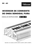
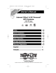
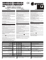
®
BXM12/30-U BXM12/50-U *
BXM12/30-B BXM12/50-B *
*
STAZIONE DI ALIMENTAZIONE
POWER SUPPLY STATION
COFFRET CHARGEUR SUPERVISÉ
ENGLISH
ITALIANO
FRANÇAIS
DESCRIZIONE GENERALE
DESCRIPTION
CARACTÉRISTIQUE GÉNÉRALE
BXM12/30-U, BXM12/50-U, BXM12/30-B e BXM12/50-B sono Stazioni di Alimentazione studiate per l'integrazione della corrente fornita
dalle centrali antifurto in impianti particolarmente esigenti. I vari modelli sono costituiti da un Modulo Alimentatore e da un'Elettronica di
Controllo alloggiati in un contenitore metallico. Il Modulo Alimentatore
fornisce la tensione continua a partire dalla tensione di rete. Il contenitore è protetto contro i tentativi di sabotaggio ed è in grado di alloggiare
un Accumulatore che garantisce l'alimentazione in caso di black-out
(mancanza della tensione d'ingresso).
Caratteristiche: BXM12/30-U e BXM12/50-U:
10 LED di segnalazione (rete, guasto, uscita 1, uscita 2, uscita 3,
guasto caricabatteria, switching disconnesso, batteria assente,
batteria bassa, batteria disconnessa);
2 uscite open-collector (rete e guasto);
Morsetti anti-sabotaggio;
Caratteristiche: BXM12/30-B e BXM12/50-B:
Interfaccia bus BPI; il bus BPI IN (collegato alla centrale) è completamente disaccoppiato dal bus BPI OUT(i Bus sono galvanicamente
isolati); le risposte del bus BPI OUT (locale) vengono riportate verso
la centrale sul BPI IN.
2 LED di segnalazione (rete e guasto);
Possono essere connessi fino ad 8 BXM12-B sul bus BPI. L'indirizzo
viene impostato tramite i microinterruttori 25 (il dip switch marcato
con "1" viene ignorato).
The BXM12/30-U BXM12/50-U, BXM12/30-B, BXM12/50-U Power
Supply Stations have been especially designed to satisfy the backup
power needs of particularly demanding Burglar control systems.
All models have a PCB and a Power Supply Module located inside a
metal box.
The Power Supply Module supplies continuous voltage from the Mains.
The tamper protected box can house a standby Battery for power in the
event of black-out (input voltage failure).
BXM12/30-U, BXM12/50-U Features
10 Warning LEDs (Mains, Trouble, Output 1, Output 2, Output 3,
Battery Charger Trouble, Switching Power Supply Disconnected, No
Battery, Low Battery, Battery Disconnected.
2 Open-collector Outputs (Mains and Trouble)
Tamper Microswitches
BXM12/30-B, BXM12/50-B Features
BPI Bus Interface: the Control panel BPI IN Bus is totally uncoupled
from the BPI OUT Bus (electrically isolate).
The result of BPI OUT Bus polling is sent to the Control panel via the
BPI-IN Bus.
2 warning LEDs (Mains and Trouble)
Up to 8 BXM12-B version can be connected to the BPI Bus. The
Addresses can be assigned via the DIP Switches 25 (DIP Switch 1 has
no effect).
Les alimentations en coffret BXM12-U et BXM12-B ont été spécialement
développées pour les systèmes intrusion nécessitant un maintien de
l’alimentation lors de la coupure du secteur.
Les 2 alimentations sont composées d’un module de contrôle et de câblage,
ainsi que d’une carte d’alimentation.
La carte d’alimentation peut auto-rectifier la tension d’alimentation en
réduisant celle-ci lorsqu’elle est trop élevée.
Le coffret est autoprotégé, et peut recevoir une batterie de 17Ah 12V.
Caractéristique BXM12/30-U et BXM12/50-U
10 LEDs de défauts (Défaut Secteur, Sortie 1, Sortie 2, Sortie 3,
Charge Batterie, Carte Alimentation déconnectée, Absence Batterie,
Batterie Basse, Batterie Déconnectée.
2 Sortie Collecteur-Ouvert (Secteur et Défaut)
Contact d’Autoprotection
Caractéristique BXM12/30-B et BXM12/50-B
Bus BPI: le Bus BPI IN de la centrale est totalement isolé du Bus BPI
OUT (isolement galvanique).
2 Sortie Collecteur-Ouvert (Secteur et Défaut)
Jusqu’à 8 BXM12-B peuvent être connectée sur le BPI Bus.
L’adressage est effectué via des DIP Switches 25 (DIP Switch 1 n’a
pas d’effet).
INSTALLAZIONE
Locate the Power Supply Station as near as possible to the devices it
must supply, this will reduce the voltage drop on the connections to a
minimum.
Choose the place of installation, and lay the cables.
Drill the holes for the Power Supply Station and snatch bracket (7).
Check for water pipes and wiring before drilling.
Pull the wires through the wire entry (6).
Using the screw locations (1), mount the Power Supply Station then
attach the snatch bracket (7). Do not to over tighten the screw as this
may damage the bracket.
If you are connecting the Power Station to the BPI bus: use the DIP
switches (25) to assign its Address.
Complete the connections on the terminal board 23. Do not connect
the input voltage (230 V) at this point. The Mains wires should be
bunched and stripped but not soldered.
Using the terminal board (15), connect the input voltage (230V ~+/
-10% 50/60Hz) to the Power Supply Module.
IMPORTANT
In order to comply with safety regulations, the Line must be connected
La Stazione di Alimentazione deve essere installata il più vicino possibile alle apparecchiature che deve alimentare, in modo da ridurre al
minimo le cadute di tensione sui collegamenti.
Scelto il punto in cui installare la Stazione di Alimentazione, posare tutti
i cavi necessari.
Praticare i fori per il fissaggio della Stazione di Alimentazione e quello per
il fissaggio del tassello antistrappo (7), facendo attenzione alle condutture
idrauliche e ai fili della corrente.
Passare i cavi per i collegamenti attraverso l'apertura 6, quindi fissare la Stazione di Alimentazione tramite i fori 1 e il tassello antistrappo
7, senza serrare troppo la vite per non rompere le alette di battuta.
Se la Stazione di alimentazione deve essere collegata al bus BPI,
impostare il suo indirizzo tramite i microinterruttori 25:
Effettuare i collegamenti sulla morsettiera 23: per il momento non collegare la tensione di ingresso (230V). I fili della rete devono essere
uniti tra loro con una fascetta e NON devono essere stagnati.
Collegare la tensione di ingresso (230V~+/-10% 50/60Hz) alla
morsettiera 15 del Modulo Alimentatore.
ATTENZIONE
Per un'installazione a norme, la Fase deve essere collegata al morsetto
[L] e il morsetto [
] deve essere collegato alla Terra. Inoltre, deve
essere previsto un idoneo dispositivo di sezionamento e di protezione
dell'alimentazione di rete nell'impianto elettrico dell'edificio, in accordo alle norme vigenti (legge 46/90): per esempio, un interruttore
magneto-termico bipolare.
Sistemare l'accumulatore nell'apposito spazio, quindi collegarlo all'Elettronica di Controllo tramite i connettori 5. Per collegare la batteria
da 17 Ah sostiture i connettori 5 con dei capicorda ad occhiello che
vanno fissati alla batteria con una vite ed un dado.
Fare attenzione a non invertire le polarità dei collegamenti; se
ciò si dovesse verificare, sostituire il fusibile 19 (T8A250V)
DESCRIZIONE DEI MORSETTI
Uscite di alimentazione protette da fusibile
autoripristinante.
Morsetti di massa.
Uscita antisabotaggio Normalmente Chiusa: si
apre quando si rimuove il pannello frontale della
Stazione di Alimentazione oppure quando
quest'ultima viene strappata dal muro.
Uscita Open Collector Normalmente Appesa di
Guasto Rete: si collega alla massa quando si
accende la spia ~.
Uscita Open Collector Normalmente Appesa di
Guasto Generico: si collega alla massa quando
si accende la spia G .
Bus BPl OUT per il collegamento con altri
dispositivi BPI.
1[O1]
3[O2]
5[O3]
2-4-6-11
[-]
INSTALLATION
to terminal [L] and the Earth to terminal [
], and an bipolar isolating
device (e.g. an automatic isolating switch) must be connected to protect
against overvoltage and short-circuit .
Locate the battery then, using the connectors (5), connect it to the
PCB. When connecting a 17 Ah battery, use eyelet terminals instead of
the connectors (5). The eyelet terminals must be secured by means
of a screw and nut.
Ensure the connection polarity is correct. In the event of
unintentional inversion, change the fuse 19 (T8A250V).
INSTALLATION
Installer l’alimentation au plus proche des sytèmes à l’alimenter, ceci
à fin de limiter au maximun les pertes en ligne.
Choisir un lieu et amener les câbles nécessaire
Percer les tous de fixation du boîtier et du support d’autoprotection
(7).
Contrôler la position des canalisations d’eau et les câbles existant
avant de percer.
Passer les câbles par le trou (6).
Fixer le boîtier et le support d’autoprotection (7), prendre gare de ne
pas endommager les câbles avec les vis.
Si vous connectez la Station d’alim au bus BPI: utilisé les DIP switches
(25) pour adresser.
Completez les connexions sur le bornier 23. Ne pas connecter le
secteur (230 V) à ce stade.
Utiliser le bornier (15), pour connecter le secteur (230V ~+/-10%
50/60Hz) à la carte d’alimentation.
IMPORTANT
La connexion doit être conforme à la réglementation, la phase doit être
connecté [L] et la terre sur [
], ainsi qu’une protection électrique
adaptée et conforme.
Installer la batterie et connectez la (5). Lorsque vous connectez une
batterie 17 Ah, modifier les oeillets (5). Dans ce cas, des écrous seront
utilisés pour sécuriser le montage .
Assurez vous de la polarité de la batterie. En cas d’inversion
changer le fusible 19 (T8A250V).
v(V)
i(A)
TERMINAL DESCRIPTION
DESCRIPTION DES BORNES
-
(1)
Supply outputs protected by automatic restoral
fusee
Sortie protégée par fusible réarmable
0
-
Ground terminals
Borne de terre (0V)
Sortie Normalement fermé: ouvert lorsque le boîtier est
ouvert ou si il n'est plus connecté au mur.
7-8[AS]
-
-
Normally Closed Tamper output: opens when the
front panel of the Power Supply Station is
removed, or when the Power Supply Station is
snatched from the wall.
9
[RETE]
0
0,1
Normally Open repeat output for Mains Trouble:
connects to negative when the LED ~turns ON.
Sortie normalement ouverte copie des Défauts: connecté au
négatif lorsque la LED ~est à ON.
10
[G]
0
0,1
Normally Open repeat output for Power-Supply
Cutout Module: connects to negative when the
Sortie normalement ouverte copie de la coupure carte alim:
-
-
BPI OUT Bus (for BPI devices)
Bus BPI OUT (vers périphérique BPI)
-
-
BPI IN Bus (to be connected to the control panel)
Bus BPI IN (vers centrale KYO)
12-13-14-15
[+][C][R][-]
16-17-18-19
Bus BPI IN per il collegamento con la centrale.
[+][C][R][-]
(1) Da ogni uscita è possibile assorbire al massimo 1,8 A però la
somma delle correnti assorbite dai morsetti 1[O1], 3[O2] e 5[O3] non
deve essere superiore alla Corrente Massima Erogabile dalla
Stazione di Alimentazione (v. "CARATTERISTICHE TECNICHE")..
LED G turns ON.
(1) Each output provides a maximum current draw of 1.8 A, however,
the total current draw of terminals 1[O1], 3[O2] and 5[O3] must not
exceed the maximum current supplied by the Power Supply Station
(refer to "TECHNICAL FEATURES")..
connecté au négatif lorsque la LED G est à ON.
(1) Chaque sortie peut débiter jusqu'à 1.8 A, cependant le
courant total des sorties 1[O1], 3[O2] et 5[O3] ne doit pas
dépasser le courant disponible sur la station d'alimentation
(se referer à "CARACTERISTIQUES TECHNIQUES").
Fig. 2 -Parti della stazione di alimentazione-Power
supply Components- Identification
19
20
21
22
23
24
25
26
27
28
SW
29
30
12 V
OU T
5V
SW
NT C
12V
ON
OUT
5V
NTC
LB105- P
1 2 3 4
ON
1
1
LB105-P
1 2 3 4
SW 1
12V
12 V
5V
5V
2
IN
5V
5V
IN
1
O1
2
3
O2
4
5
6
O3
7
8
AS
9
RETE
10
G
11
12
13
14
C
R
BPI OUT
15
16
17
+
18
19
C
R
BPI IN
8
1
2
O1
3
O2
(b)
7
4
5
O3
6
8
7
AS
9
10
RETE
G
11
23b
12
13
14
15
C
R
BP I O UT
16
+
17
18
C
R
BP I IN
19
23a
3
14
6
15
16
18
17
(a)
4a
5
9
4b
13
1
12
1
11
10
CARATTERISTICHE TECNICHE
TECHNICAL FEATURES
BXM12
Modello /30-U /50-U /30-B
Tensione di ingresso.
/50-B
230 V ~ ÷10% 50/60 Hz
0,9 A
Corrente assorbita (max.). 0,5 A 0,9 A 0,5 A
Tensione di uscita max (prima di
14,7 V _ +/-1%
sgancio sicurezza) .
Tensione di uscita min (a batteria
scarica)
10,2 V _ +/-1%
13,8 V
Tensione nominale fornita
Corrente nominale 3,0 A 5,0 A
3,0 A
Temperatura di funzionamento
Classe di isolamento
Dimensioni (L x H x P)
Peso (con accumulatori da 17 Ah)
Livello di prestazione (CEI 79-2)
Model
Modèle
Input voltage
Tension Secteur
Maximum current draw
Consommation Max
Output voltage
Tension de Sortie
Minimum output voltage
Tension Mini de Sortie
Nominal voltage
5,0 A
Massima corrente permanente
2,4 A 4,0 A 2,4 A
4,0 A
erogabile
1.8 A
Massima corrente su [+] BPI OUT
Tempo di ricarica (fino all'80% della
24 h
batteria)
12 V - 17 Ah
YUASA
Batterie allocabiliMarcaModello(*) O
NP 17-12 FR (*)
equivalenti con classe d'infiammabilità
o/or12 V - 7 Ah
dell'involucro UL94-V2 o migliore
YUASA
NP 7-12 FR (*)
Soglia di Sconnesione Modulo
14,7 V
Alimentatore
11,0 V
Soglia di segnalazione Batteria Bassa
Soglia di Sconnessione Accumulatore
CARACTERISTIQUES TECHNIQUE
BXM12
10,2 V
5÷40 °C
I
240 x 348 x 97 mm
Nominal current supplied
Courant Nominal
Maximum current supplied
Courant Maximum
Maximum current supplied on output
Courant Maximum par sortie
Temps de Recharge (jusqu'à 80% de
la capacité batterie)
Recharge Time (up to 80% capacity)
Battery compartmentMakeModel(*) An
equivalent with a case flame class of
UL94-V2 or higher
Compartiment batterie (*) ou
équivalent conforme à UL94-V2 ou
supérieur
Power Module Shutdown Threshold
Seuil de coupure de l'alimentation
Low Battery Signal Threshold
Seuil de signalement Batterie basse
Battery Shutdown Threshold
Seuil de coupure Batterie Basse
Operating temperature
Température de fonctionnement
Insulation level
Classe d'isolation
Dimensions (W x H x D)
Dimensions (L x H x E)
8,6 Kg
Weight (with 17 Ah battery)
Poids (avec batterie 17 Ah)
II
Security grading (CEI 79-2)
Grade de sécurité (CEI 79-2)
PAR TS
ID E N T IF IC A T IO N
ID E N T IF IC A T IO N
D E S P A R T IE S
1
4 wa l l -m o u n t s c r e w l o c a ti o n s
(Ø 4 m m )
4 tro u s d e fi x a ti o n a u m u r ( Ø
4 mm)
2
PCB
C a rte d e g e s ti o n
D e v i a to r e a n ti s tra p p o .
A l l o g g i a m e n to p e r u n
a c c u m u l a to r e d a 1 2 V , 1 7 A h (a )
o p p u r e d a 1 2 V , 7 A h (b ).
C o n n e tto ri p e r l 'a c c u m u l a to r e .
3
S n a tc h m i c ro s wi tc h
M i c ro s wi tc h d 'A P
4
1 2 V , 1 7 A h (a ) o r 1 2 V , 7 A h (b )
b a tte r y h o u s i n g
L o g e m e n t B a tte ri e 1 2 V , 1 7 A h
(a ) o u 1 2 V , 7 A h ( b )
5
B a tte ry c o n n e c to rs
C o n n e c te u r s B a tte r i e
F o ro p e r il p a s s a g g io d e i c a v i.
6
W i re e n try
E n tré e p a s s a g e d e c â b l e
ID E N T IF IC A Z IO N E P A R T I
F o r i (4 ) p e r i l fi s s a g g i o d e l l a
S ta zi o n e d i A l i m e n ta zi o n e (Ø 4
m m ).
E l e ttro n i c a d i C o n tr o l l o .
P.
T a s s e l l o a n ti s tra p p o .
7
S n a tc h b ra c k e t
S u p p o rt d 'A P
M o d u l o A l i m e n ta to r e
S o n d a te rm i c a K S T p e r
l 'o tti m i zza zi o n e d e l l a ri c a ri c a d e l l a
b a tte r i a . (O p zi o n a l e ) V . m a n u a l e
s p e c i fi c o .
L e d d i s e g n a l a zi o n e d e l l a p re s e n za
d e l l a te n s i o n e d i u s c i ta d e l M o d u l o
A l i m e n ta to r e
8
P o we r S u p p l y M o d u l e
K S T T h e rm a l p ro b e
(a c c e s s o ry i te m ) fo r
o p ti m i za ti o n o f th e b a tte ry
c h a r g e p ro c e s s
C a rte d 'a l i m e n ta ti o n
9
S o n d e th e r m i q u e K S T
(a c c e s s o i r e ) p o u r o p ti m i s e r l a
c h a r g e b a tte r i e
10
P o we r M o d u l e o u tp u t v o l ta g e
LED
L E D s e c te u r d e l a c a r te
d 'a l i m e n ta ti o n
11
C o n n e c to r to b e u s e d fo r th e
c o n n e c ti o n o f th e P o we r
S u p p l y M o d u l e to th e o n b o a r d o u tp u t v o l ta g e c o n tr o l
c irc u it
C o n n e c te u r Å u ti l i s é p o u r
i n te r c o n n e c te r l a c a r te
a l i m e n ta ti o n e t l a c a rte d e
g e s ti o n p o u r l a ré g u l a ti o n
12
P o we r S u p p l y o u tp u t v o l ta g e
tr i m m e r (D O N O T A D J U S T )
13
A u x i l i a r y o u tp u t
C o n n e tto re p e r i l c o l l e g a m e n to d e l
M o d u l o A l i m e n ta to r e a l l 'E l e ttro n i c a
d i C o n tr o l l o .
14
C o n n e c to r to b e u s e d fo r th e
c o n n e c ti o n o f th e P o we r
S u p p l y M o d u l e to th e P C B
M o rs e tti e ra p e r i l c o l l e g a m e n to
d e l l a T e n s i o n e d i In g r e s s o
(2 3 0 V ~ , 5 0 H z).
15
V i te d a r i m u o v e re p e r a p r i r e i l
M o d u l o A l i m e n ta to r e .
16
F u s i b i l e d i p r o te zi o n e d e l M o d u l o
A l i m e n ta to r e
17
C h i o d i n o d a ri m u o v e re p e r a p r i re i l
M o d u l o A l i m e n ta to r e .
18
F u s i b i l e (T 8 A 2 5 0 V ) c o n tro
l 'i n v e rs i o n e a c c i d e n ta l e d e l l e
p o l a ri tà d e l l 'a c c u m u l a to re
19
C o n n e tto re p e r i l c o l l e g a m e n to d e l
M o d u l o A l i m e n ta to r e
20
C o n n e tto re p e r i l c o l l e g a m e n to a l
c i r c u i to d i c o n tr o l l o te n s i o n e d i
u s c i ta
21
C o n n e tto re s u l m o d u l o d i
a l i m e n ta zi o n e p e r i l c o l l e g a m e n to
a l c i rc u i to d i c o n tro l l o te n s i o n e d i
u s c i ta , p o s to s u l l a s c h e d a .
T r i m m e r d i re g o l a zi o n e fi n e d e l l a
te n s i o n e d i u s c i ta (N O N
M O D IF IC A R E ).
U s c i ta a u s i l i a r i a .
C o n n e tto re p e r i l c o l l e g a m e n to
d e l l a s o n d a te rm i c a
M o rs e tti e ra p e r i c o l l e g a m e n ti
(E n tr a m b e l e v e rs i o n i ).
22
23
M o rs e tti a n ti s a b o ta g g i o e u s c i te
O p e n C o l l e c to r (s o l o v e r s i o n e - U )
23a
M o rs e tti B P I (s o l o v e r s i o n e -B )
23b
24
Trim m e r d e ré g la g e d e la
te n s i o n d e s o r ti e ( N E P A S
M O D IF IE R
S o r ti e A u x i l i a i re
C o n n e c te u r Å u ti l i s é p o u r
i n te r c o n n e c te r l a c a r te
a l i m e n ta ti o n e t l a c a rte d e
g e s ti o n p o u r l a p u i s s a n c e
T e r m i n a l b o a r d fo r th e i n p u t
B o rn e s d e c o n n e x io n d u
v o l ta g e c o n n e c ti o n ( 2 3 0 V ~ ,
s e c te u r (2 3 0 V ~ , 5 0 H z)
5 0 H z)
S c r e ws (to b e r e m o v e d wh e n
th e P o we r S u p p l y M o d u l e i s
V i s d e fi x a ti o n
opened)
F u s i b l e d e l a c a rte
P o we r S u p p l y M o d u l e fu s e
a l i m e n ta ti o n
P i n ( to b e re m o v e d wh e n th e
P i n ( p e r m e t l e d é m o n ta g e d e
P o we r S u p p l y M o d u l e i s
l a g ri l l e )
opened)
F u s ib le (T 8 A 2 5 0 V ) Å
F u s e (T 8 A 2 5 0 V ) p ro te c ts
p ro te c ti o n c o n tre l e s
a g a i n s t u n i n te n ti o n a l b a tte ry
i n v e rs i o n s d e p o l a ri té d e
p o l a ri ty i n v e r s i o n
b a tte r i e
P o we r S u p p l y M o d u l e
C o n n e c te u r p o u r l a c a r te
c o n n e c to r
d 'a l i m e n ta ti o n
C o n n e c te u r Å u ti l i s é p o u r
C o n n e c to r to b e u s e d fo r th e
i n te r c o n n e c te r l a c a r te
c o n n e c ti o n to th e o u tp u t
a l i m e n ta ti o n e t l a c a rte d e
v o l ta g e c o n tr o l c i rc u i t
g e s ti o n p o u r l a ré g u l a ti o n
T h e r m a l P ro b e c o n n e c to r
C o n n e c te u r s o n d e th e r m i q u e
T e r m i n a l b o a r d (fo r b o th
m o d e ls)
T a m p e r M i c ro s wi tc h e s a n d
O p e n -c o l l e c to r o u tp u ts (o n l y
fo r - U v e r s i o n )
B P I T e r m i n a l s (o n l y fo r -B
v e rs i o n )
T a m p e r m i c ro s wi tc h
A d d r e s s D IP S wi tc h e s ( o n l y
fo r - B v e rs i o n )
B o r n e d e s c â b l a g e s (p o u r l e s
2 m o d è le s )
A P e t s o r ti e c o l l e c te u r o u v e r t
(s e u l e m e n t B X M 1 2 -U )
B u s B P I (s e u l e m e n t p o u r
B X M 1 2 -B )
AP
D IP S wi tc h e s d 'a d re s s a g e
(s e u l e m e n t p o u r B X M 1 2 - B )
L E D O r a n g e = T ro u b l e ; L E D
V e r te = S e c te u r ( s u r B X M 1 2 B)
D e v i a to r e a n ti s a b o ta g g i o .
M i c ro i n te rr u tto ri p e r l 'i m p o s ta zi o n e
d e l l 'i n d i r i zzo (s o l o v e r s i o n e -B .
L E D g i a l l o : g u a s to ; L E D v e r d e : r e te
(U n i c i d u e L E D s p re s e n ti n e l l a
v e rs i o n e - B )
C o n n e tto re p e r i l c o l l e g a m e n to
m i c ro s wi tc h a n ti s a b o ta g g i o .)
P o n ti c e l l o p e r l 'i m p o s ta zi o n e d e l
l i v e l l o B P I i n u s c i ta j > 5 V
p re i m p o s ta zi o n e ; k > 1 2 V
P o n ti c e l l o p e r l 'i m p o s ta zi o n e d e l
l i v e l l o B P I i n e n tra ta j > 5 V
p re i m p o s ta zi o n e ; k > 1 2 V
26
A m b e r L E D = T r o u b l e ; G re e n
L E D = M a i n s (o n -B v e rs i o n )
27
T a m p e r M i c ro s wi tc h c o n n e c to r
C o n n e c te u r A P
28
B P I OU T Level Jum per
j > 5 V ( a t d e fa u l t)
k >12 V
29
B P I IN L e v e l J u m p e rj
V ( a t d e fa u l t) k > 1 2 V
P o n ti c e l l o d a i m p o s ta re K s e i l
l i v e l l o B P I i n e n tra ta è 5 V .
30
B P I IN L e v e l J u m p e r K : to
b e i n s e r te d wh e n th e B P I IN
L e ve l is s e t a t 5 V
P o n te t N i v e a u B P I O U T
j > 5 V ( p a r d é fa u t)
k >12 V
P o n te t N i v e a u B P I IN
j > 5 V ( p a r d é fa u t)
k >12 V
25
> 5
P o n te t N i v e a u B P I IN K :
D o it p o u r u n n iv e a u à 5 V
DESCRIZIONE DELLE SPIE
P.
WARNING LEDs
LEDs de Défaut
Se accesa indica presenza di un guasto
generico
G
ON indicates Generic Trouble
ON indique un défaut Générique
OFF indicates input (230 V) voltage
failure:- check for Mains voltage;check that the fuse 17 is intact;check that the Power Supply Module
is connected to the PCB
OFF indique un défaut secteur (230
V) :- contrôler la présence secteur;contrôler que le fusible 17 est intact;contrôler l'interconnexion entre la
carte alim et de gestion.
OFF indicates output voltage failure
on terminals [O1], [O2] or [O3]
respectively:- in the event of input
voltage failure (LED
OFF): check that the battery is properly
OFF indique un défaut de sortie [O1],
[O2] ou [O3] respectivement:- si le
secteur est absent (LED
OFF): contrôler la connexion et la charge
Se spenta indica la mancanza della tensione
d'ingresso (230V):- controllare la presenza della
tensione di rete;- controllare che il fusibile 17
non sia bruciato:- controllare che il Modulo
Alimentatore sia collegato all'Elettronica di
Controllo.
Se spente indicano la mancanza della tensione
di uscita rIspettivamente sui morsetti [O1], [O2]
o [O3]:- se manca la tensione di ingresso (spia
spenta), controllare che l'accumulatore sia
presente, connesso e carico (spie
,a e
1
_
2
_
3
_
connected and charged (LEDs
,
, a et
s OFF);- contrôler que le courant
de la batterie (LEDs
a and s OFF);- check that the
current draw of the terminal does not
exceed 1.8 A. Power will be restored
when the current draw drops to the
permitted limit.
consommé n'est pas supérieur à 1.8
A. La tension sera rétablie lorsque le
courant consommé sera en dessous
de la limite.
ON indicates Power Supply Module
Trouble
ON indique un défaut de la carte
alimentation
m
ON indicates that the Power Supply
Module has shutdown due to
excessive output voltage (over 0.5V).
The shutdown value depends on the
temperature (if the KST termal probe
is installed). The standby battery will
supply the voltage to the Power
Supply Station until the Power
Supply Module is restored. The
Power Supply Module will be
restored automatically when its
output voltage drops below the Safety
threshold, if this does not occur, it
must be replaced.
ON indique la carte alim est arrêtée
due à une tension de sortie au
dessus de 0.5V. La valeur d'arrêt
dépend de la température (si la
sonde KST est installée). La batterie
sera utilisée jusqu'au retour de la
tension de la carte alimentation. La
carte d'alimentation sera restaurée
lorsque la tension repassera sous le
seuil de sécurité.
a
ON indicates that the battery has
shutdown due to voltage drop (Safety
threshold 10.2 V). This condition can
damage the battery. The battery will
be restored as soon as it is
recharged by the Power Supply
Module.
ON indique que la batterie a été
déconnectée (Seuil de sécurité 10.2
V). Cet état peut endommager la
batterie. La batterie sera reconnectée
dés que la carte alim l'aura
rechargée.
Se accesa indica che la Stazione di
Alimentazione è priva dell'accumulatore: nel
caso in cui venga a mancare la tensione di
ingresso (spia
spenta) l'alimentazione dei
dispositivi collegati alla Stazione è impossibile.
Controllare che il fusibile 21 sia intatto, che
l'accumulatore sia collegato e che la sua
tensione non sia inferiore alla soglia di
sconnessione. In quest'ultimo caso occorre
sostituire l'accumulatore.
ON indicates that the Power Supply
Station has battery trouble.
Therefore, in the event of input
voltage failure (LED
OFF), the
system will be unable to feed the
Power Supply Station peripherals.
Check that the fuse 21 is intact; check that the battery is connected
and its voltage is above shutdown
threshold. The battery must be
replaced if the voltage remains below
the shutdown threshold.
ON indique un défaut batterie. En
cas d'absence secteur (LED
OFF), la station d'alimentation ne
pourra alimenter les périphériques.
Contrôler si le fusible 21 est intact; contrôler si la batterie est connectée
et si sa tension n'est pas sous le
seuil critique. La batterie devra être
changée si elle se trouve sous le
seuil critique d'arrêt
Se accesa indica che l'accumulatore è scarico:
nel caso in cui venga a mancare la tensione di
ingresso (spia
spenta) l'alimentazione dei
dispositivi collegati alla Stazione non è
garantita. Attendere alcune ore per vedere se
l'accumulatore si ricarica, altrimenti sostituirlo.
ON indicates that the battery is flat.
Therefore, if the input voltage fails
(LED
OFF) the system will be
unable to feed the Power Supply
Station peripherals. Allow the battery
to recharge for several hours, if the
battery does not recharge it must
replaced.
ON indique une batterie. En cas
d'absence secteur(LED
OFF) la
station d'alimentation ne pourra
alimenter les périphériques. Laissez
la batterie se rechargée quelque
heure si la recharge n'est pas
effectuée, changer la batterie.
s spente);- controllare che la corrente
assorbita dal morsetto non superi 1,8 A; in tal
caso, riportando l'assorbimento nel limite
ammesso, la tensione si ripristinerà.
Se accesa indica la presenza di un guasto sul
Modulo alimentatore.
Se accesa indica che il Modulo Alimentatore è
stato sconnesso perché la sua tensione di
uscita ha superato di 0,5V il valore previsto (il
valore di sgancio dipende dalla temperatura, se
è installato il dispositivo KST): nel frattempo
l'alimentazione della Stazione e dei dispositivi
ad essa collegati è garantita dall'accumulatore.
Se la tensione di uscita del Modulo
Alimentatore torna sotto la soglia di sicurazza,
viene riconnesso automaticamente, altrimenti
esso deve essere sostituito.
Se accesa indica che l'accumulatore è stato
sconnesso perché la sua tensione è scesa sotto
la soglia di sicurezza ( 10,2V) che potrebbe
danneggiarlo in modo irreversibile. Esso sarà
riconnesso non appena il Modulo Alimentatore
sarà in grado di ricaricarlo.
s
ISTISBL3BXM12-B 1.0 201005 P7.0