1
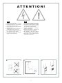
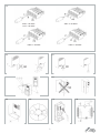
Installation, operation and maintenance manual Manuale di installazione, uso e manutenzione Air conditioner for outdoor electric enclosure Condizionatori da parete per armadi elettrici outdoor EMO AT T E N T I O N ! Read carefully and completely before installation. Keep the manual until unit decommissioning. Leggere attentamente e completamente prima dell’installazione e conservare fino allo smaltimento. C17000212R00 AT T E N T I O N ! ENG • Working on the unit only by qualified and authorized personnel. • Power supply rating on unit nameplate must comply with mains rating. • Always switch power supply off before opening the unit. • Carefully follow manual instructions on condensate discharge connection. • If an air filter is installed, check it and, when clogged, clean or replace. • Air inlets and outlets must be com pletely free from obstruction. F.1 ITA • Solo personale qualificato e autorizzato può effettuare servizio tecnico all’unità. • La tensione di alimentazione riportata sulla targa dati del condizionatore deve corrispondere a quella della rete. • Togliere alimentazione al condizio natore prima di aprirlo. • Seguire attentamente le istruzioni del manuale per lo scarico condensa. • Se è installato un filtro aria controllarlo e, quando intasato, pulirlo o sostituirlo. • Gli ingressi e le uscite dell’aria devono essere liberi da ostruzioni. F.2 F.3 2 F.4 400V 3~ 50-60Hz 230V ~ 50-60Hz 115V ~ 50-60Hz 400V 2~ 50-60Hz 440V 2~ 50-60Hz F.5 F.6 F.8 F.7 F.9 F.10 F.11 3 F.12 ENG 1. Introduction This manual contains general informations valid for each model of EMO range. Specific informa tions as dimensional drawing, wiring diagram, technical data are contained in the specific tech nical document issued for each singol unit. 2. Intended use and operating limits for the cooling unit The cooling units described in this manual are designed and built to cool the air inside outdoor enclosures in order to protect components sensi tive to thermal shock and, at the same time, pro viding an IP54 protection level against the infil tration of contaminating and strong substances. The ambient air temperature must be included from minimum -20°C to maximum +50°C (+55°C only if it is indicated on the data plate) for a prop er functioning. 3. Updates. Pavarini Components reserves the right to up date its product and relative manuals based on technical progress without prior notice. Please note that at the time of sale, this manual and rel ative product cannot be considered inadequate only because they are not subject to above-men tioned updates. 4. Supply Inside the packaging you will find: cooling unit 1 installation, operating and mainte 1 nance manuall CE conformity certificate 1 test certificate 1 1 6/8 nuts 2 6/8 flat washers 3 6/8 dowels 10x5 mm self-adhesive sealing strip 4 1 piece of flexible hose for discharging 5 1 condensate 12x2x100 mm 1 ... 4 (figure F.7) (figure F.9) 5 5. Prior to assembly. During transport and storage the cooling • unit must be kept in the position clearly in dicated on the packaging (figure F.1.0), and must not be exposed to temperatures high er than 70°C. Upon receipt, check the packaging has not • been damaged during shipping. Ambient air temperature, where the enclo • sure is to be installed, must be no high er than 50°C and should never exceed the cooling unit’s maximum operating tem perature which is specified on its rating plate. The unit must be positioned far away from heat sources and flows of hot air. Make sure enclosure protection level is • IP54 or higher. Should this not be the case excessive condensation could form. Conse quently seal well all areas where cables pass and all other openings in the enclo sure. Check that the external environment does • not contain excessive concentrations of contaminating solids and/or strong chemi cals. Check that the flows of air leaving and en • tering the cooling unit are not obstructed by walls or objects that are too close. For this purpose, in the case of the external air flow, verify the minimum distances (fig • • ure F.2), while in the case of the internal air flow, make sure there are no obstructions caused by the switchboard components. The supply voltage available must corre spond to the features given on the cooling unit’s rating plate. The cooling unit must be installed with the enclosure air suction hole in the highest pos sible point. If the cooling unit has to be installed on a door, make sure the door can take the weight. Before making the holes and slits on the enclosure make sure the fixing elements and couplings will not interfere with the equipment inside the enclosure itself. 6. Assembly. Disconnect power before starting any work inside the switchboard. The cooling unit can be applied externally on the electric enclosure without the need for any additional accessories (just those you will find inside the standard kit supplied with the unit). Drill the holes and make the necessary cuts on the switchboard using the drilling tem plate supplied with the unit. Fit the sealing strip on the cooling unit on the side connected to the enclosure and follow the assembly diagram (fig ure F.7). To lift the cooling unit safely use the two eyebolts or the two lifting brackets on the top of the cooling unit (figure F. 3). 7. Condensate discharge hose. The condensate which, depending on the am bient temperature and humidity conditions, forms on the exchanger that cools the enclosure air, is not a malfunction but a normal phenomenon of the cooling unit. The condensate is taken out side through a hose at the bottom of the cooling unit. The transparent plastic hose, supplied with the unit, must be connected to this discharge (figure F.9). This plastic hose can be connect ed to another one with the same diameter to car ry the condensate to another point so when it is discharged it is where there can be no slipping hazard for personnel. In this case, make sure the condensate flows without any hindrance. Avoid horizontal lengths of more than 0.5 me tres, lengths with a reverse gradient and the ac cidental formation of traps (figure F.5). The end of the condensate discharge hose must always be free, never immersed, so never place the end of the discharge hose inside condensate collec tion trays (figure F.6). If the cooling unit is used with the doors of the enclosure open, excessive quantities of condensate will form and this is an unauthorised condition of use (figure F.8). We suggest using a position switch on the door that will stop the cooling unit if the door is opened. 8. Electrical connection. 8.1 Safety Attention! The electrical connection must be done by specialised and authorised person nel. Switch power off to the enclosure before making the connection. Check that the availa ble supply voltage corresponds to the character istics given on the cooling unit’s data plate. The supply of electricity to the cooling unit must be protected by an isolating device / fuse or circuit breaker with a distance between the contacts of at least 3 mm when open according to the indi cated settings. Connect the cables following the instructions on the wiring diagram. After a stop the cooling unit must not be started again imme 4 diately. For this reason we suggest using a timed control that delays restarting 3 minutes. Discon nect the cooling unit before electrically testing the enclosure. 8.2 Versions with an autotransformer (EMO..G) These bi-phase versions are set for two supply voltages: 440V 2~ 50-60Hz and 400V 2~ 5060Hz. If the available power supply voltage is 440V 2~ 50-60Hz connect terminals L1(0) and L3(440) of black plug (figure F.4). If the available power supply voltage is 400V 2~ 50-60Hz con nect L1(0) and L2(400) to same plug. 9. First start up and adjustment. If, prior to installation, the cooling unit was left in an incorrect position (figure F.1), wait at least 8 hours before switching it on otherwise 30 min utes are more than enough for the oil to return to the compressor after which the cooling unit can be powered. The enclosure air suction fan starts working immediately, rendering the temperature even inside the enclosure. If this temperature is higher than the threshold value set on the adjust ment thermostat both the compressor and exter nal air fan start working, causing the cooling cy cle to start. The latter stops when the inside temperature reaches the low limit of the operating differen tial that has a fixed value of 4 K. The thermostat is factory set at 35 °C. To alter this set value ac cess the thermostat. With the graduated scale, from 20 to 46 °C, you may alter the set tempera ture as wanted (figure F.10). To save energy and minimise the production of condensation we rec ommend not to go below 30 °C. 10. Maintenance. Caution! Before embarking on any mainte nance work, switch current off to the enclo sure. The cooling unit is the low maintenance type so no filter change is required. The on ly jobs that need doing are the internal compo nents with compressed air at a maximum pres sure of 4 bar (figure F.11) and which should be checked regularly. Job Frequency Check the external air Every 3 heat exchanger and months clean if necessary. Check effectiveness Every 3 of the condensate dis months charge. Check the fans for any Every 6 overheating or exces months sive vibrations. Any repairs that may need doing must only be done by specialised and authorised personnel and using original spare parts only. 11. Technical information. 11.1 Operating principle. The cooling unit for electric enclosures works on the basis of a refrigeration circuit consisting of four main components: compressor, evaporator, condenser and expansion device (figure F.12). The circuit is hermetically sealed and the refrig erant circulates inside it. The refrigerant used is R134a (or R407C), chlorine free and harmless for the ozone layer. The unit is divided into two hermetically separated sections where the am bient air and enclosure air do not come into con tact with one another and are treated separately. The compressor (CP) compresses the refrig erant and takes it to a high pressure and high temperature. The compressor then pushes the refrigerant through a heat exchanger coil, called condenser (C), where it is cooled by ambient air thus passing from the gas to the liquid state. At the liquid state it then passes through the capil lary (EXP) and as it is at a much lower pressure, nebulizes at the outlet. It is then received by the heat exchanger coil, called evaporator (E), by means of which it absorbs heat from the enclo sure air and passes from a liquid state to gas. The enclosure is cooled down in this manner. The gas is then drawn back into the compressor and the above described cycle is repeated. 11.2 Safety devices. The refrigeration circuit is fitted with a high pres sure safety switch HP (figure F.12) set at maxi mum cooling unit working pressure. If the thresh old is exceeded, the pressure switch stops the compressor working. It is the automatically re settable type. The low pressure safety switch LP stop the compressor when the suction pressure decrease under the fixed threshold. Also the low pressure safety switch is automatucally resetta ble. The fans and compressor have a thermal cut-out switch inside that stops them in the case of anomalous over temperatures. A condensa tion control pressure switch (FSD) is mounted on condenser fan; it controls the condenser fan speed to keep the condensing temperature con stant. 11.3 Disposal. Caution! The cooling unit contains R134a (or R407C) refrigerant and small quantities of lubricating oil. These substances pollute and must not be dumped. Replacement, repairs and final disposal must be seen to by experts. NOTE Keep the documentation in a dry place. 12. Troubleshooting Malfunction Conditions Causes Remedy It fails to cool The internal fan works, the external fan and com pressor do not work. The temperature inside the enclosure is lower than what is set on the adjustment thermostat. This is not a malfunction of the cooling unit. To verify functioning when testing, lower the thermostat setting until the compressor and external fan start working and then reset the thermostat. No component works The adjustment thermostat has failed No electricity getting to the unit. Compressor, external and internal fan work Cooling unit empty of fluid Change the adjustment thermostat This is not a malfunction of the cooling unit. Make sure the power cable has been connected well to the • terminals. Check that the cubicle doors and switches are closed • Call a refrigeration expert or the Manufacturer’s Technical Assist ance Service Call a refrigeration expert or the Manufacturer’s Technical Assist ance Service Change the internal fan’s capacitor Change the internal fan Change the amperometric protector Compressor mechanical failure Compressor and external fan work, internal fan does not work External and internal fan work, compressor does not work Internal fan capacitor failed Internal fan failed Compressor’s amperometric protector failed (external to the compressor, where present) Relay or PTC for compressor starting failed Capacitor for compressor starting failed (where present) Compressor motor electrical failure High pressure safety switch failed It is not cooling enough External and internal fans work, compressor works all the time Inside fan works, external fan and compressor work irregularly Enclosure door open Thermostat set point incorrect High pressure safety switch triggered: Ambient temperature over the maximum work • ing limit Heat exchanger coil (condenser) either dirty or • clogged Thermal protector inside the compressor triggered: Ambient temperature over the maximum work • ing limit Heat exchanger coil (condenser) either dirty or • clogged Too much ambient air inside the enclosure Enclosure door closed Enclosure protection level is below IP54 External and internal fans work, compressor works irregularly Too much condensate forming Compressor contactor failed (where present) Cooling unit under sized for the heat dissipated inside the enclosure Insufficient gas in the cooling unit The enclosure/cooling unit connecting seal has been fitted incorrectly 5 Change the relay or PTC for compressor starting Change the capacitor for compressor starting Call a refrigeration expert or the Manufacturer’s Technical Assist ance Service Call a refrigeration expert or the Manufacturer’s Technical Assist ance Service Change the contactor Change the cooling unit with another of greater capacity Call a refrigeration expert or the Manufacturer’s Technical Assist ance Service Check thermostat setpoint • • • • Ventilate the premises where the enclosure is installed to keep ambient temperature lower. Clean the exchanger with compressed air and detergent Ventilate the premises where the enclosure is installed to keep ambient temperature lower. Clean the coil with compressed air and detergent This is not a malfunction of the cooling unit. Close the enclosure door or disable the cooling unit This is not a malfunction of the cooling unit. Seal enclosure open ings, e.g. for passage and upward path of wires Check seal and remedy ITA 1. Introduzione Questo manuale contiene informazioni di carat tere generale valide per tutti i modelli della gam ma EMO. Ulteriori informazioni quali disegni di mensionali, dati tecnici, schemi elettrici sono in seriti nell’allegato tecnico rilasciato per ogni sin gola unità. • 2. Destinazione d’uso e limiti di funziona mento del condizionatore. I condizionatori descritti in questo manuale so no progettati e realizzati per il raffreddamento dell’aria contenuta all’interno dei quadri di co mando da esterno, al fine di proteggerne i com ponenti sensibili alle sollecitazioni termiche e, nello stesso tempo, forniscono una protezione IP54 contro l’ingresso di sostanze contaminanti e di agenti aggressivi. Per un corretto funziona mento del condizionatore la temperatura dell’aria esterna deve essere compresa tra un minimo di -20°C ed un massimo di +50°C (+55°C per le unità per cui espressamente indicato sulla tar ga dati). • 3. Aggiornamenti. La Pavarini Components si riserva il diritto di ag giornare i prodotti ed i relativi manuali senza pre avviso, in base al progresso della tecnica. Di contro, al momento della commercializzazione, il presente manuale ed il relativo prodotto non possono essere considerati inadeguati solo per ché non aggiornati col progresso di cui sopra. 4. Fornitura Nell’imballo sono contenuti: 1 condizionatore 1 manuale di installazione, uso e manu tenzione 1 certificato di conformità CE 1 certificato di collaudo 1 6/8 dadi 2 6/8 rondelle piane 3 6/8 grani 4 1 nastro di guarnizione autoadesiva 10x5 mm 5 1 spezzone tubo flessibile per scarico condensa 12x2x100 mm 1 5 4 (figura F.7) (figura F.9) 5. Prima del montaggio Durante il trasporto e l’immagazzinamento il • condizionatore deve essere mantenuto nel la posizione chiaramente indicata sull’im ballo (figura F.1) e non deve essere espo sto a temperature superiori a 70°C. Al ricevimento, controllare che l’imballo non • presenti danni da trasporto. La temperatura dell’aria ambiente, nel si • to di installazione dell’armadio, non deve superare i 50°C e, in ogni caso, non deve essere superiore alla massima temperatura di esercizio del condizionatore, specificata nella targa dati dello stesso. Posizionare il condizionatore in modo da rimanere lontani da fonti di calore o flussi di aria calda. Verificare che il quadro abbia un grado IP54 • o superiore. In caso contrario si potrebbe verificare formazione eccessiva di conden sa. Di conseguenza, sigillare bene le zone di passaggio cavi ed eventuali altre apertu re nell’armadio. Verificare che l’ambiente esterno non pre • senti concentrazioni di contaminanti solidi e/o di contaminanti chimici aggressivi in mi sura eccessiva. • • • Verificare che i flussi di aria in ingresso e in uscita dal condizionatore non siano ostaco lati da pareti ed oggetti troppo vicini. A tale scopo, per quanto riguarda il flusso d’aria esterno, verificare le distanze minime (figu ra F.2), mentre per il flusso d’aria interno, verificare che non vi siano ostacoli derivanti dai componenti presenti nel quadro. La tensione di alimentazione disponibile de ve rispondere alle caratteristiche riportate sulla targa dati del condizionatore. Il condizionatore deve essere installato con il foro di aspirazione aria armadio nel punto più alto possibile. Se il condizionatore deve essere installato su una porta, accertarsi che questa sia in grado di sopportarne il peso. Prima di realizzare i fori e le feritoie sul l’armadio, accertarsi che gli elementi di fis saggio e di accoppiamento non andranno ad interferire con le apparecchiature conte nute nell’armadio stesso. 6. Montaggio Prima di effettuare qualsiasi operazione all’ in terno del quadro sconnettere l’alimentazione. Il condizionatore può essere applicato sull’ arma dio elettrico, senza la necessità di ulteriori ac cessori che non siano quelli presenti nel kit di montaggio standard in dotazione. Eseguire sul quadro i fori e i tagli necessari, utilizzando l’ap posita dima di foratura fornita. Applicare, dove previsto, la guarnizione al condizionatore sul lato di accoppiamento all’armadio e seguire lo sche ma di montaggio indicato (figura F.7). Per solle vare il condizionatore in sicurezza, si possono utilizzare i due golfari o le due staffe di solleva mento nella parte superiore del condizionatore (figura F.3). 7. Scarico condensa La condensa che, in funzione delle condizio ni di temperatura e umidità ambiente, si forma sullo scambiatore che raffredda l’aria dell’arma dio, non è un’anomalia ma una caratteristica del funzionamento normale del condizionatore. La condensa viene portata all’esterno per mezzo di un tubo nella parte inferiore del condizionato re. A questo scarico, si deve collegare il tubo in plastica trasparente parte della fornitura (figura F.9). Questo tubo in plastica può essere raccor dato ad un altro tubo di pari diametro per condur re la condensa in altra posizione, in modo che lo scarico avvenga in area non a rischio di sci volamento del personale. In questo caso, assi curarsi che la condensa scorra senza ostaco li. Evitare tratti oltre 0,5 metri di tubo orizzonta le, tratti in contro pendenza e formazione invo lontaria di sifoni (figura F.5). L’estremità del tubo di scarico della condensa deve sempre essere libera, mai immersa. Quindi non collocare mai l’estremità del tubo di scarico all’interno di conte nitori di raccolta condensa (figura F.6). Utilizzare il condizionatore con armadio a porte aperte ge nera quantità eccessive di condensa: questa è una condizione di utilizzo non autorizzata (figu ra F.8). Per prevenire tale inconveniente è consi gliato l’utilizzo di un interruttore di posizione sulla porta che arresti il funzionamento del condizio natore in caso di apertura. 8. Collegamento elettrico. 8.1 Sicurezza Attenzione! Il collegamento elettrico deve es sere eseguito da personale specializzato e autorizzato. Togliere tensione all’armadio pri 6 ma di effettuare il collegamento. Controllare che l’armadio non sia alimentato e che la tensio ne corrisponda a quella riportata sulla targa dati del condizionatore. Allo scopo di garantire la pro tezione dell’alimentazione utilizzare opportuni sezionatori / fusibili o interruttori magnetotermici, con distanza tra i contatti di almeno 3 mm con contatti aperti secondo le tarature indicate sul la targa dati. Eseguire il collegamento dei cavi secondo quanto indicato nello schema elettri co. Il condizionatore dopo una fermata non de ve essere reinserito immediatamente. Si consi glia pertanto l’uso di un comando temporizzato che ritardi il reinserimento di 3 minuti. Scolle gare il condizionatore prima delle prove di col laudo dell’armadio. 8.2 Modelli con autotrasformatore (EMO..G) Questi modelli bifase sono predisposti per due tensioni di alimentazione: 440V 2~ 50-60Hz e 400V 2~ 50-60Hz. Se l’alimentazione disponibile è 440V 2~ 50-60Hz collegare i morsetti L1(0) e L3(440) del connettore nero (figura F.4). Vice versa se l’alimentazione disponibile è 400V 2~ 50-60Hz collegare L1(0) e L2(400) sul medesi mo connettore. 9. Primo avvio e regolazione. Nel caso che il condizionatore, prima del mon taggio, sia stato lasciato in posizione non cor retta (figura F.1), attendere almeno 8 ore prima di metterlo in funzione. Diversamente, 30 minu ti saranno sufficienti al ritorno dell’olio nel com pressore, dopodiché sarà possibile dare tensio ne al condizionatore. Il ventilatore che aspira l’aria dell’armadio, si metterà subito in funzione uniformando la temperatura interna dell’arma dio. Se questa temperatura dovesse essere su periore alla soglia impostata sul termostato di re golazione, si inseriranno il compressore e il ven tilatore dell’aria esterna determinando l’inizio del ciclo di raffreddamento. Quest’ultimo terminerà quando la temperatura interna raggiungerà il li mite inferiore del differenziale di funzionamento, che ha un valore fisso pari a 4 K. Il termostato è impostato a 35°C in fabbrica. Per variare il set di temperatura accedere al termostato. La sca la graduata, da 20 a 46 °C, permette di variare il set di temperatura secondo il valore desidera to (figura F.10). Per il risparmio energetico e mi nimizzare la produzione di condensa si consiglia tuttavia di non scendere al di sotto di 30 °C. 10. Manutenzione. Attenzione! Prima di eseguire qualsiasi intervento togliere tensione all’armadio. Il condizionatore è del tipo a bassa manutenzione, quindi non richiede sostituzione o cambio del fil tro. Gli unici interventi richiesti riguardano la puli zia dei componenti interni, da effettuarsi con aria compressa avente pressione max di 4 bar (figu ra F.11) e il controllo periodico, secondo quanto di seguito riportato: Intervento Frequenza Controllo ed eventuale Ogni 3 mesi pulizia dello scambiatore di calore aria esterna. Controllare l’efficienza Ogni 3 mesi dello scarico condensa. Controllare i ventilatori Ogni 6 mesi per eventuali surris caldamenti o eccessive vibrazioni. Eventuali riparazioni devono essere effettuate solo da personale specializzato autorizzato. 11. Informazioni tecniche. 11.1 Principio di funzionamento. Il condizionatore per armadi elettrici opera sulla base di un circuito frigorifero costituito da quat tro componenti principali: compressore, evapo ratore, condensatore e dispositivo di espansione (figura F.12). Il circuito è stagno e in esso circo la il fluido refrigerante. Quest’ultimo è R134a (o R407C), privo di cloro, con danno nullo all’ozo no atmosferico. L’unità e suddivisa in due sezio ni, ermeticamente separate, dove vengono trat tate l’aria ambiente e l’aria dell’armadio senza che vengano in contatto tra di loro. Il compres sore (CP) comprime il fluido frigorigeno portan dolo ad alta pressione e alta temperatura. Spin to dal compressore, il fluido passa nella batte ria di scambio termico, detta condensatore (C), dove viene raffreddato dall’aria ambiente, pas sando così da gas a liquido. Allo stato di liquido passa poi attraverso il capillare (EXP) all’uscita dal quale, trovandosi a pressione e temperature molto più basse, nebulizza. Viene ricevuto, allo ra, dalla batteria di scambio termico detta eva poratore (E), attraverso la quale assorbe calo re dall’aria dell’armadio passando, così, da liqui do a gas. L’armadio in questo modo si raffred da. Il gas viene quindi nuovamente aspirato dal compressore per ripetere il ciclo già descritto. controllo della condensazione (FSC); la veloci tà di rotazione del ventilatore è regolata al fine di mantenere costante la temperatura di conden sazione. 11.3 Smaltimento. Attenzione! il condizionatore contiene fluido frigorigeno R134a (o R407C) e piccole quan tità di olio lubrificante. Questi composti sono inquinanti e non devono essere dispersi nell’am biente circostante. La sostituzione, la riparazio ne e lo smaltimento finale devono essere ese guiti da esperti. 11.2 Dispositivi di controllo e di sicurezza. Il circuito frigorifero è dotato di un pressostato di alta pressione HP (figura F.12) tarato alla mas sima pressione di esercizio del condizionatore. Nel caso in cui la soglia venga superata il pres sostato interrompe il funzionamento del com pressore. E’ del tipo a ripristino automatico. Il pressostato di bassa pressione LP ferma il compressore quando la pressione di aspirazio ne scende al di sotto della soglia prefissata. An che il pressostato di bassa è a riarmo automa tico. I ventilatori e il compressore sono dotati (internamente o esternamente) di un protettore termico che interrompe il funzionamento in ca so di sovra temperature anomale. Il ventilatore lato ambiente è dotato di un pressostato per il NOTA Conservare attentamente la documentazione in luogo sicuro e asciutto. 12. Risoluzione anomalie Anomalia Condizioni Cause Rimedio Non raffredda Ventilatore interno funziona, ventilatore esterno e compressore non funzionano Temperatura in armadio inferiore a quella di taratura del termostato di regolazione Nessun componente funziona Termostato di regolazione guasto Manca tensione all’unità Non è un’anomalia del condizionatore. Per verificare il funzionamento al collaudo, abbassare la taratura del termostato fino all’avviamento di compressore e ventilatore esterno e poi ripristinare la taratura Sostituire il termostato di regolazione Non è un’anomalia del condizionatore. Verificare che il cavo di alimentazione sia ben inserito nei • morsetti. Controllare che porte armadio e interruttori siano chiusi • Chiamare tecnico frigorista o Servizio Assistenza Tecnica del Costruttore Chiamare tecnico frigorista o Servizio Assistenza Tecnica del Costruttore Sostituire condensatore elettrico ventilatore interno Sostituire ventilatore interno Sostituire protettore amperometrico (ove presente) Compressore, funzionano ventilatore esterno e interno Compressore e ventilatore esterno funzionano, ventilatore interno non funziona Ventilatori esterno e interno funzionano, compres sore non funziona Condizionatore scarico di fluido Guasto meccanico del compressore Condensatore elettrico ventilatore interno guasto Ventilatore interno guasto Protettore amperometrico compressore guasto (esterno al compressore, ove presente) Relè o PTC avviamento compressore guasto Condensatore elettrico avviamento compressore guasto (ove presente) Motore interno compressore guasto Pressostato di alta pressione guasto Non raffredda sufficientemente Ventilatori esterno e interno funzionano, compres sore funziona continuamente Ventilatore interno funziona, ventilatore esterno e compressore funzionano a intermittenza Porta armadio aperta Taratura setpoint termostato non corretta Pressostato alta pressione scattato: Temperatura ambiente superiore al limite massimo • di funzionamento Batteria di scambio termico (condensatore) sporca • o intasata Protettore termico interno compressore scattato : Temperatura ambiente superiore al limite massimo • di funzionamento Batteria di scambio termico (condensatore) sporca • o intasata Quantità eccessiva di aria ambiente nell’armadio Porta armadio chiusa Armadio con grado di protezione inferiore a IP54 Ventilatori esterno e interno funzionano, compres sore funziona a intermittenza Eccessiva formazione di condensa Contattore compressore guasto (dove presente) Condizionatore sottodimensionato rispetto al calore dissipato in armadio Insufficiente carica di gas nel condizionatore Guarnizione accoppiamento armadio / condizionatore applicata non correttamente 7 Sostituire relè o PTC avviamento compressore Sostituire condensatore elettrico avviamento compressore (ove presente) Chiamare tecnico frigorista o Servizio Assistenza Tecnica del Costruttore Chiamare tecnico frigorista o Servizio Assistenza Tecnica del Costruttore Sostituire contattore Sostituire condizionatore con altro di potenza maggiore Chiamare tecnico frigorista o Servizio Assistenza Tecnica del Costruttore Verificare taratura setpoint termostato • • • • Ventilare il locale in cui è contenuto l’armadio per ottenere temperature ambiente più basse. Pulire lo scambiatore con aria compressa e detergente Ventilare il locale in cui è contenuto l’armadio per ottenere temperature ambiente più basse. Pulire lo scambiatore con aria compressa e detergente Non è un’anomalia del condizionatore. Chiudere la porta armadio o disabilitare il condizionatore Non è un anomalia del condizionatore. Sigillare le aperture dell’armadio, ad es. passaggi e risalite cavi Controllare guarnizione e rimediare GUARANTEE / GARANZIA / GARANTIE / GARANTIE / GARANTÍA ENG The manufacturer guarantees its product free from Quality defects. It also guarantees for: 24 months all the product’s components starting from the date they are put on the market and when they are used in the following conditions: 1) When the temperatures of the panel or enclosure are no higher or lower than those indicated on the rating plate. 2) In circuits or systems that do not require cooling capacities higher than those indicated on the rating plate. 3) On premises where the temperatures are no higher or lower than those indicated on the rating plate. 4) On panels or enclosures with at least a minimum protection level of IP54 5) When the instructions given in the “operating and maintenance” manual, provided with each single product, are fully complied with. This guarantee does not cover any damage to the product due to: a) using a type and quantity of gas in the cooling circuit different to that indicated on the rating plate. b) using the product on unsuitable premises: where there is an acid or corrosive atmosphere. For each component found to be faulty during the term of the guarantee, Pavarini Components Spa will, according to its unquestionable judgement, repair and/or substitute the faulty components free of charge either at its factory or in one of its authorised companies. Any additional expenses incurred for removing, handling and installation if required are not payable by Pavarini Components Spa. Any maintenance work needed and requested by the customer care/of his premises, even if it is during the term of the guarantee, will be billed according to the ANIMA rates. The products repaired or substituted in no way modify the time the guarantee starts or ends. Pavarini Components spa can in no way be held liable except for repairing or substituting faulty products and if such products have to be redelivered it will be on a Carriage Forward basis. It is the customer’s re sponsibility to see to the correct earthing, installation and power supply of the product in compliance with current standards. Reference must be made to the current laws in force regarding liability for damage caused by a faulty product, for which Pavarini Components Spa is insured. For the purposes of such laws, please note that the date the product was placed on the market is the date written on its rating plate. To benefit from the guarantee terms and relative product information it is essential to have the purchase document and the serial number of the product which you will find on the rating plate. The rating plate is printed on plastic and the writing will remain for a long time even on premises and in environments where conditions are particularly bad. ATTENTION: the guarantee is automatically invalidated if the product is tampered with in any way. ITA ITA Il produttore garantisce che il prodotto e’ esente da difetti Qualitativi. Garantisce inoltre per: 24 mesi tutti i componenti del prodotto, a partire dalla data di immissione sul mercato, quando opera nelle seguenti condizioni: 1) Con temperature del quadro o dell’armadio non superiori e non inferiori alle temperature indicate nella targa dati. 2) In circuiti o sistemi che non richiedano potenze di raffreddamento superiori alla potenza indicata sulla targa dati 3) In ambienti con temperature non superiori o non inferiori a quelle indicate sulla targa dati 4) Su quadri o armadi con almeno un grado di protezione minimo IP54 5) Quando si rispettano in forma integrale le norme presenti sul manuale di “uso e manutenzione “ in dotazione per ogni singolo prodotto. Questa garanzia non copre eventuali danni causati al prodotto per: a) Introduzione nel circuito frigorifero di gas diversi per quantità e qualità da quello indicato nella targa dati b) Funzionamento del prodotto in ambienti non idonei quali, atmosfera acida o corrosiva. Per ogni componente risultato difettoso, nel periodo di garanzia, la Pavarini Components Spa provvederà a proprio insindacabile giudizio alla riparazione e/o sostituzione, presso i propri stabilimenti o in azienda autorizzata dalla medesima, senza alcun addebito dei componenti risultati difettosi. Eventuali spese aggiuntive derivanti dalla rimozione, movimentazione ed eventuale installazione non saranno imputabili a Pavarini Components Spa. Gli interventi di manutenzione, anche nel periodo di garanzia, richiesti dal cliente presso la propria sede, saranno fatturati secondo le tariffe ANIMA. I prodotti riparati o sostituiti, non modificano in alcun modo i tempi di inizio o cessazione della garanzia stessa. La Pavarini Components Spa non si assume alcuna responsabilità, oltre a quella di riparare o sostituire i prodotti risultati difettosi e l’eventuale riconsegna del prodotto sarà effettuata in Porto Assegnato. Risulta a carico del cliente, che se ne assume tutte le responsabilità, la corretta messa a terra, l’istallazione e l’alimentazione elettrica del prodotto in conformità delle normative vigenti. Eventuali responsabilità per danni risultanti da prodotto difettoso si fa riferimento alla disciplina legislativa in vigore, per la quale, Pavarini Components Spa gode di relativa polizza assicurativa. Ai fini delle legge stessa , si informa che la data di immissione del prodotto sul mercato e’ la data rilevabile sulla targa dati del prodotto stesso. Per accedere al diritto di garanzia ed alle relative informazioni sul prodotto, e’ indispensabile essere in possesso del documento di acquisto e del nr. di matricola del prodotto indicato sulla targa dati . La targa dati e’ stampata su supporto plastico e garantisce una lunga permanenza delle scritte anche in locali ed ambienti particolarmente gravosi. ATTENZIONE: La garanzia decade automaticamente in caso di una qualsiasi manomissione del prodotto. DEU MANUFACTURER/PRODUTTORE/HERSTELLER/FABRICANT/PRODUCTOR 46020 PEGOGNAGA - MANTOVA - ITALY - STRADA CÀ BRUCIATA, 5 TEL. +39 0376-554511 - FAX +39 0376-558606 www.pavarinicomponents.com - email:[email protected] 8 DEK EGO SKY MIX BLU FAN DLK WID 46020 PEGOGNAGA - MANTOVA - ITALY - STRADA CÀ BRUCIATA, 5 - TEL. +39 0376-554511 - FAX +39 0376-558606 www.pavarinicomponents.com - email:[email protected]