1
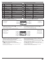
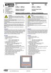
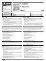
31100125
GB DIGITAL MULTIMETER
Installation manual
I374 GB I 10 13
LOVATO ELECTRIC S.P.A.
I MULTIMETRO DIGITALE
24020 GORLE (BERGAMO) ITALIA
VIA DON E. MAZZA, 12
TEL. 035 4282111
FAX (Nazionale): 035 4282200
FAX (International): +39 035 4282400
E-mail [email protected]
Web www.LovatoElectric.com
The complete operating manual is
downloadable from website
www.lovatoelectric.com
Il manuale operativo completo è
scaricabile dal sito www.lovatoelectric.com
Manuale d’installazione
DMG800
GB
Available in English at www.LovatoElectric.com/I272IGBFE.pdf
I
Available in Italian at www.LovatoElectric.com/I272IGBFE.pdf
F
Available in French at www.LovatoElectric.com/I272IGBFE.pdf
E
Available in Spanish at www.LovatoElectric.com/I272IGBFE.pdf
D
Available in German at www.LovatoElectric.com/I272D.pdf
CZ
Available in Czech at www.LovatoElectric.com/I272CZ.pdf
PL
Available in Polish at www.LovatoElectric.com/I272PL.pdf
RU
Available in Russian at www.LovatoElectric.com/I272RU.pdf
WARNING!
– Carefully read the manual before the installation or use.
– This equipment is to be installed by qualified personnel, complying to current standards, to avoid
damages or safety hazards.
– Before any service work on the device, remove all the voltages from measuring and supply inputs and
short-circuit the CT input terminals.
– The manufacturer cannot be held responsible for electrical safety in case of improper use of the equipment.
– Products illustrated herein are subject to alteration and changes without prior notice. Technical data
and descriptions in the documentation are accurate, to the best of our knowledge, but no liabilities for
errors, omissions or contingencies arising there from are accepted.
– A circuit breaker must be included in the electrical installation of the building. It must be installed
close by the equipment and within easy reach of the operator. It must be marked as the disconnecting
device of the equipment: IEC /EN 61010-1 § 6.11.2.1.
– Clean the device with a soft dry cloth; do not use abrasive products, liquid detergents or solvents.
ATTENZIONE!!
– Leggere attentamente il manuale prima dell’utilizzo e l’installazione.
– Questi apparecchi devono essere installati da personale qualificato, nel rispetto delle vigenti normative
impiantistiche, allo scopo di evitare danni a persone o cose.
– Prima di qualsiasi intervento sull’apparecchio, togliere tensione dagli ingressi di misura e di
alimentazione e cortocircuitare i trasformatori di corrente.
– Il costruttore non si assume responsabilità in merito alla sicurezza elettrica in caso di utilizzo
improprio del dispositivo.
– I prodotti descritti in questo documento sono suscettibili in qualsiasi momento di evoluzioni o di
modifiche. Le descrizioni ed i dati a catalogo non possono pertanto avere alcun valore contrattuale.
– Un interruttore o disgiuntore va compreso nell’impianto elettrico dell’edificio. Esso deve trovarsi in
stretta vicinanza dell’apparecchio ed essere facilmente raggiungibile da parte dell’operatore. Deve
essere marchiato come il dispositivo di interruzione dell’apparecchio: IEC/ EN 61010-1 § 6.11.2.1.
– Pulire l’apparecchio con panno morbido, non usare prodotti abrasivi, detergenti liquidi o solventi.
INTRODUCTION
The DMG800 multimeter has been designed to combine the maximum possible easiness of operation
together with a wide choice of advanced functions. Thanks to its flush-mount 96x96mm housing, the
DMG800 joins the modern design of the front panel with the tool-less mounting of the device body and
the expansion capability of the rear panel, where it is possible to mount plug-in modules of EXP series.
The graphic LCD graphic display offers a user-friendly interface. The rich variety of functions, makes the
DMG series multimeters the ideal choice for a wide range of applications.
INTRODUZIONE
Il multimetro DMG800 è stato progettato per unire la massima semplicità di utilizzo con una ampia scelta
di funzioni avanzate. In esecuzione per montaggio a pannello con dimensioni standard 96x96mm, il
DMG800 unisce il moderno design del frontale alla praticità di montaggio e alla possibilità di espansione
sul retro, dove è possibile alloggiare moduli della serie EXP. Il display grafico LCD consente una
interfaccia utente chiara ed intuitiva. La ricca dotazione di funzioni fa dei multimetri serie DMG la
soluzione ideale per un campo di applicazioni molto ampio.
DESCRIPTION
– Flush-mount housing, 96x96mm
– Graphic LCD display, 128x80 pixels, white backlight, 4 grey levels
– Keyboard with 4 keys for visualization and setting
– Easy and fast navigation
– Compatible with LV, MV, HV applications
– Texts for measures, setup and messages in 5 languages
– Reading of more than 300 electrical parameters
– Harmonic analysis of voltage and current up to 31.st order
– Expansion bus for maximum 4 plug-in modules EXP series
– Advanced programmable I/O functions
– True RMS measurements
– Continuous (gapless) sampling
– High accuracy
– Sealable terminal covers
– Settings lock through sealable dip-switch.
DESCRIZIONE
– Esecuzione da incasso 96x96mm.
– Display LCD grafico 128x80 pixel, retroilluminato, 4 livelli di grigio.
– 4 tasti per visualizzazione ed impostazione.
– Navigazione rapida e semplice.
– Compatibile con reti BT, MT e AT.
– Testi per misure, impostazioni e messaggi in 5 lingue.
– Più di 300 grandezze elettriche misurate.
– Analisi armonica di tensione e corrente fino al 31.mo ordine.
– Bus di espansione per max 4 moduli plug-in serie EXP…
– Funzioni di I/O avanzate programmabili.
– Misure in vero valore efficace (TRMS).
– Acquisizione continua (gapless).
– Elevata accuratezza.
– Coprimorsetti piombabili.
– Blocco impostazioni tramite interruttore piombabile.
KEYBOARD FUNCTIONS
MENU key - Used to enter or exit from visualization and setting menus.
and keys - Used to scroll display pages, to select among possible choices and to modify settings
(increment-decrement).
key - Used to rotate through sub-pages, to confirm a choice, to switch between visualization modes.
FUNZIONE DEI TASTI FRONTALI
Tasto MENU – Serve per entrare o uscire dai vari menu sia di visualizzazione che di impostazione.
Tasti e - Servono per lo scorrimento fra le pagine video, per la selezione fra le possibili scelte
presentate a display e per la modifica di impostazioni (incremento/decremento).
Tasto
- Serve per lo scorrimento delle sotto-pagine, per confermare una scelta effettuata e per
passare da una modalità all’altra di visualizzazione.
VIEWING OF MEASUREMENTS
– The and keys allow to scroll the pages of viewed measurements one by one. The page being
viewed is written in the title bar.
– Some of the readings may not be shown, depending on the programming and the wiring of the device (for
instance, if programmed-wired for a three-phase without neutral system, L-N voltage page is not shown).
– For every page, the
key allows to rotate through several sub-pages (for instance to show the
highest/lowest peak for the selected readings).
– The sub-page viewed is indicated in the status bar on the bottom of the display by one of the
following icons:
• IN = Instantaneous value - Actual instantaneous value of the reading, shown by default every time
the page is changed.
• HI = Highest peak - Highest peak of the instantaneous value of the relative reading. The HIGH
values are stored and kept even when auxiliary power is removed. They can be cleared using the
dedicated command (see commands menu).
• LO = Lowest peak - Lowest value of the reading, stored from the time the DMG is powered-on. It is
resetted using the same command used for HI values.
• AV = Average value - Time-integrated value of the reading. Allows showing measurements with
slow variations. See integration menu in setup chapter.
• MD = Maximum Demand - Maximum peak of the integrated value. Stored in non-volatile memory
and it is resettable with dedicated command.
• GR = Bar graphs - Shows the measurements with bar graphs.
VISUALIZZAZIONE DELLE MISURE
– I tasti e consentono di scorrere le pagine di visualizzazione misure una per volta. La pagina
attuale è riconoscibile tramite la barra del titolo.
– Alcune delle misure potrebbero non essere visualizzate in funzione della programmazione e del
collegamento dell’apparecchio (ad esempio se programmato per un sistema senza neutro le misure
riferite al neutro non vengono visualizzate).
– Per ogni pagina, il tasto
consente di accedere a delle sotto-pagine (ad esempio per visualizzare i
valori massimi e minimi registrati per la misura selezionata).
– La sottopagina visualizzata correntemente è indicata in basso a sinistra da una delle seguenti icone:
• IN = Valore istantaneo - Valore istantaneo attuale della misura, visualizzato di default ogni volta
che si cambia pagina.
• HI = Valore massimo istantaneo - Valore più alto misurato dal multimetro per la relativa misura. I
valori HIGH vengono memorizzati e mantenuti anche in assenza di alimentazione. Possono essere
azzerati tramite apposito comando (vedere menu comandi).
• LO = Valore minimo istantaneo - Valore più basso misurato dal multimetro dal momento della
messa in tensione. Viene resettato con lo stesso comando usato per i valori HI.
• AV = Valore integrato - Valore della misura integrato (mediato) nel tempo. Consente di vedere una
misura con variazioni lente. Vedere menu Integrazione.
• MD = Massimo valore integrato - Valore massimo del valore integrato (max demand). Rimane
memorizzato in memoria non volatile ed è resettabile con apposito comando.
• GR = Barre grafiche - Visualizzazione delle misure tramite barre grafiche.
1
31100125
I374 GB I 10 13
Example of display page with numeric indication
Esempio di pagina con indicazioni numeriche
1 - Unit of measure
1 - Unità di misura
2 - Measurement
2 - Misura
3 - Title bar
3 - Titolo pagina
4 - Phase indication
4 - Indicazione fasi
5 - Sub-page indication
5 - Indicazione sottopagina
Example of display page with bar graphs
Esempio di pagina barre grafiche
1 - Unit of measure
1 - Unità di misura
2 - Measurement
2 - Misura
3 - Phase indication
3 - Indicazione fasi
4 - HI-LO markers
4 - Indicatori HI-LO
– The user can define to which page and sub-page the display must return to after a period of time has
elapsed without any keystroke.
– If needed, it is possible to set the multimeter so that the display will remain always in the position in
which it has been left.
– To set these functions see menu M02 – Utility.
– L’utente ha la possibilità di specificare su quale pagina e su quale sottopagina il display deve ritornare
automaticamente dopo che è trascorso un tempo senza che siano premuti dei tasti.
– Volendo è anche possibile programmare il multimetro in modo che la visualizzazioni resti sempre
nella posizione in cui è stata lasciata.
– Per l’impostazione di queste funzioni vedere menu M02 – Utilità.
TABLE OF DISPLAY PAGES
TABELLA DELLE PAGINE DEL DISPLAY
Selection with and Selezione con e Selection with
N°
PAGE
SUB PAGES
1
PHASE-TO-PHASE VOLTAGES - V (L1-L2), V(L2-L3), V(L3-L1), V(LL)EQV
HI
LO
AV
2
PHASE-TO-NEUTRAL VOLTAGES - V(L1-N), V(L2-N), V(L3-N), V(L-N)EQV HI
LO
AV
3
PHASE AND NEUTRAL CURRENTS - I(L1), I(L2), I(L3), I(N)
HI
4
ACTIVE POWER - P(L1), P(L2), P(L3), P(TOT)
5
REACTIVE POWER - Q(L1), Q(L2), Q(L3), Q(TOT)
6
PAGINE
GR
1
TENSIONI CONCATENATE - V (L1-L2), V(L2-L3), V(L3-L1), V(LL)EQV
HI
LO
AV
GR
GR
2
TENSIONI DI FASE - V(L1-N), V(L2-N), V(L3-N), V(L-N)EQV
HI
LO
AV
GR
LO
AV MD GR
3
CORRENTI DI FASE E DI NEUTRO - I(L1), I(L2), I(L3), I(N)
HI
LO
AV MD GR
HI
LO
AV MD GR
4
POTENZA ATTIVA - P(L1), P(L2), P(L3), P(TOT)
HI
LO
AV MD GR
HI
LO
AV MD GR
5
POTENZA REATTIVA - Q(L1), Q(L2), Q(L3), Q(TOT)
HI
LO
AV MD GR
APPARENT POWER - S(L1), S(L2), S(L3), S(TOT)
HI
LO
AV MD GR
6
POTENZA APPARENTE - S(L1), S(L2), S(L3), S(TOT)
HI
LO
AV MD GR
7
POWER FACTOR - PF(L1), PF(L2), PF(L3), PF(EQ)
HI
LO
AV
7
FATTORE DI POTENZA - PF(L1), PF(L2), PF(L3), PF(EQ)
HI
LO
AV
8
FREQUENCY-ASYMMETRY - F, ASY(VLL), ASY(VLN), ASY(I)
HI
LO
AV
8
FREQUENZA - ASIMMETRIA - F, ASY(VLL), ASY(VLN), ASY(I)
HI
LO
AV
9
PH-PH VOLTAGE HARMONIC DISTORTION - THD-V(L1-L2),
THD-V(L2-L3), THD-V(L3-L1)
HI
LO
AV
GR
9
DISTORSIONE ARMONICA TENSIONI L-L - THD-V(L1-L2),
THD-V(L2-L3), THD-V(L3-L1)
HI
LO
AV
GR
10
ANALISI ARM. TENSIONI L-L - H2…31 V(L1-L2)-V(L2-L3)-V(L3-L1)
HI
LO
AV
GR
10
DISTORSIONE ARMONICA TENSIONI L-N
THD-V(L1), THD-V(L2), THD-V(L3)
HI
LO
AV
GR
11
FORMA D’ONDA TENSIONI L-L
12
DIST. ARMONICA TENSIONI L-N
THD-V(L1),THD-V(L2),THD-V(L3)
13
ANALISI ARMONICA TENSIONI L-N - H2…31 V(L1)-V(L2)-V(L3)
14
FORMA D’ONDA TENSIONI L-N
15
DIST. ARMONICA CORRENTE - THD-I(L1), THD-I(L2) THD-I(L3)
16
ANALISI ARMONICA CORRENTE - H2…31 I(L1)-I(L2)-I(L3)
L3
17
FORMA D’ONDA CORRENTE
PARTIAL
18
CONTATORI DI ENERGIA
kWh+(TOT), kWh-(TOT), kvarh+(TOT), kvarh-(TOT), kVA(TOT)
GR
10
PH-PH VOLTAGE HARM. ANALYSIS - H2…31 V(L1-L2)-V(L2-L3)-V(L3-L1)
10
PH-N VOLTAGE HARMONIC DISTORTION
THD-V(L1), THD-V(L2), THD-V(L3)
11
PH-PH VOLTAGE WAVEFORMS
12
PH-N VOLTAGE HARMONIC DISTORTION
THD-V(L1),THD-V(L2),THD-V(L3)
13
PH-N VOLTAGE HARMONIC ANALYSIS - H2…31 V(L1)-V(L2)-V(L3)
14
PH-N VOLTAGE WAVEFORMS
15
CURRENT HARMONIC DISTORTION - THD-I(L1), THD-I(L2) THD-I(L3)
16
CURRENT HARMONIC ANALYSIS - H2…31 I(L1)-I(L2)-I(L3)
17
CURRENT WAVEFORMS
18
ENERGY METERS
kWh+(TOT), kWh-(TOT), kvarh+(TOT), kvarh-(TOT), kVA(TOT)
19
ENERGY TARIFFS
19
TARIFFAZIONE ENERGIA
20
TREND GRAPH
20
GRAFICO TREND
21
HOUR COUNTER - Hr(TOT), Hr(Partial)
21
CONTAORE - Hr(TOT), Hr(Parziale)
22
EXPANSION MODULES
22
MODULI ESPANSIONE
23
COUNTERS
CNT1
...
CNT4
23
CONTATORI
24
ANALOG INPUTS
AIN1
…
AIN8
24
INGRESSI ANALOGICI
25
ANALOG OUTPUTS
AOU1
…
AOU8
25
USCITE ANALOGICHE
L1-L2 L2-L3 L3-L1
HI
LO
AV
GR
L1-N L2-N L3-N
HI
L1
LO
L2
TAR1
AV
...
GR
TAR4
SOTTOPAGINE
GR
L1-L2 L2-L3 L3-L1
HI
LO
AV
GR
L1-N L2-N L3-N
HI
LO
AV
L1
L2
L3
GR
PARZIALI
TAR1
...
TAR4
CNT1
...
CNT4
AIN1
…
AIN8
AOU1
…
AOU8
26
LIMIT THRESHOLDS
LIM1
...
LIM8
26
SOGLIE LIMITE
LIM1
...
LIM8
27
BOOLEAN LOGIC
BOO1
...
BOO8
27
LOGICA BOOLEANA
BOO1
...
BOO8
28
ALARMS
ALA1
...
ALA8
28
ALLARMI
ALA1
...
ALA8
29
INFO-REVISION-SERIAL NO.
MODEL, REV SW, REV HW, INTERNAL TEMPERATURE
29
INFO-REVISIONI-SERIAL NR.
MODELLO, REV SW, REV HW, Nº SERIE TEMPERATURA INTERNA
30
LOGO
30
LOGO
31
(USER-DEFINED PAGE 1)
31
(PAGINA UTENTE 1)
32
(USER-DEFINED PAGE 2)
32
(PAGINA UTENTE 2)
33
(USER-DEFINED PAGE 3)
33
(PAGINA UTENTE 3)
34
(USER-DEFINED PAGE 4)
34
(PAGINA UTENTE 4)
NOTE: Some of the pages listed above may not be available if the function that they must view is not
enabled. For instance, if no alarms have been defined, then the Alarm page will not be shown.
2
Selezione con
N°
NOTA: Alcune delle pagine elencate sopra potrebbero non essere visualizzate, se la funzione visualizzata
non è abilitata. Ad esempio se non viene programmato alcun allarme, la corrispondente pagina non viene
visualizzata.
31100125
I374 GB I 10 13
DISPLAY PAGE NAVIGATION
NAVIGAZIONE FRA LE PAGINE DISPLAY
Phase-Phase voltages / Tensioni concatenate
IN = Instantaneous value
IN = Valore istantaneo
HI = Highest value
HI = Valore massimo
LO = Lowest value
LO = Valore minimo
AV = Average value
AV = Valore medio
GR = Bar graphs
GR = Barre grafiche
HI = Highest value
HI = Valore massimo
LO = Lowest value
LO = Valore minimo
AV = Average value
AV = Valore medio
GR = Bar graphs
GR = Barre grafiche
LO = Lowest value
LO = Valore minimo
AV = Average value
AV = Valore medio
MD = Max demand
MD = Max demand
Phase voltages / Tensioni di fase
IN = Instantaneous value
IN = Valore istantaneo
Phase-Neutral currents / Correnti di fase e neutro
IN = Instantaneous value
IN = Valore istantaneo
HI = Highest value
HI = Valore massimo
(continues)
(continua)
1 - Numeric values of the selected order
Valori numerici dell’ordine selezionato
MAIN MENU
– The main menu is made up of a group of graphic icons (shortcuts) that allow rapid access to
measurements and settings.
– Starting from normal viewing, press MENU key. The main menu screen is displayed.
– Press to select the required function. The selected icon is highlighted and the central part of
the display shows the description of the function.
– Press
to activate the selected function.
– If some functions are not available, the relevant icon will be disabled, that is shown in light grey.
–
etc. - Shortcuts that allow to jump to the first page of that group.
Starting from that page it is still possible to move forward-backward in the usual way.
–
- Open the password entry page, where it is possible to specify the numeric codes that unlock
protected functions (parameter setting, commands menu, etc.).
–
–
MENU PRINCIPALE
– Il menu principale è costituito da un insieme di icone grafiche che permettono l’accesso rapido alle
misure ed alle impostazioni.
– Partendo dalla visualizzazione misure normale, premere il tasto MENU. Il display visualizza il menu
rapido.
– Premere per selezionare la funzione desiderata.
L’icona selezionata viene evidenziata e la scritta nella parte centrale del display indica la descrizione
della funzione.
– Premere
per attivare la funzione selezionata.
– Se alcune funzioni non sono disponibili la corrispondente icona sarà disabilitata, cioè visualizzata in
colore grigio.
–
etc - Agiscono come scorciatoie che consentono di velocizzare
l’accesso alle pagine di visualizzazione misure, saltando direttamente al gruppo di misure selezionato,
partendo dal quale ci si potrà spostare avanti e indietro come di consueto.
–
- Impostazione del codice numerico che consente l’accesso alle funzioni protette
(impostazione dei parametri, esecuzione di comandi).
- Access point to the setup menu for parameter programming.
- Access point to the commands menu, where the authorised user can execute some clearingresetting actions.
–
–
- Punto di accesso alla programmazione dei parametri. Vedere il capitolo dedicato.
- Punto di accesso al menu comandi, dove l’utente abilitato può eseguire una serie di azioni di
azzeramento e ripristino.
1 - Voltage readings
1 - Visualizzazione tensioni
2 - Current readings
2 - Visualizzazione correnti
3 - Power readings
3 - Visualizzazione potenze
4 - Frequency - Asymmetry
4 - Frequenza - asimmetria
5 - Harmonic Analysis
5 - Analisi armonica
6 - Energy meters
6 - Contatori di energia
7 - Trend graph
7 - Grafico trend
8 - Hour readings
8 - Visualizzazione contatore
9 - Expansion modules
9 - Moduli di espansione
10 - Setup menu
10 - Impostazioni setup
11 - Commands menu
11 - Menu comandi
12 - Password entry
12 - Inserimento password
3
31100125
I374 GB I 10 13
PASSWORD ACCESS
– The password is used to enable or lock the access to the setting menu (setup) and to commands
menu.
– For brand-new devices (factory default), the password management is disabled and the access is free.
If instead the passwords have been enabled and defined, then to get access it is necessary to enter
the password first, specifying the numeric code through the keypad.
– To enable password management and to define numeric codes, see setup menu.
– There are two access levels, depending on the code entered:
• User-Level access - Allows clearing of recorded values but not editing of setup parameters.
• Advanced access level - Same rights of the user access plus settings editing-restoring.
– From normal viewing, press MENU to recall the main menu, select the password icon and press .
– The display shows the screen in the figure.
ACCESSO TRAMITE PASSWORD
– La password serve per abilitare o bloccare l’accesso al menu di impostazione ed al menu comandi.
– Per gli apparecchi nuovi di fabbrica (default), la password è disabilitata e l’accesso è libero. Se invece
le password sono state abilitate, per ottenere l’accesso bisogna prima inserire il relativo codice di
accesso numerico.
– Per abilitare l’uso delle password e definire i codici di accesso fare riferimento al capitolo
impostazione parametri.
– Esistono due livelli di accesso, a seconda del codice inserito:
• Accesso livello utente - consente l’azzeramento dei valori registrati ma non la modifica delle
impostazioni dell’apparecchio.
• Accesso livello avanzato - stessi diritti dell’utente con in più la possibilità di modificare le
impostazioni.
– Dalla normale visualizzazione misure, premere MENU per richiamare il menu principale, quindi
selezionare l’icona password e premere .
– Compare la finestra di impostazione password in figura:
–
–
–
–
Keys change the selected digit.
Key
confirms the digit and moves to the next.
Enter numeric code, then move on the key icon.
If the password code entered matches the User access code or the Advanced access code, then the
correspondent unlock message is shown.
– Once unlocked the password, the access rights last until:
• The device is powered off.
• The device is reset (after quitting the setup menu).
• The timeout period of two minutes elapses without any keystroke.
– To quit the password entry screen, press MENU key.
–
–
–
–
SETTINGS LOCK
– On the DMG800 there are two dip switches that are used to lock the access to parameter settings and
/ or to reset operations (commands menu).
– These dip switches are placed in a way that they become unaccessible once the sealable terminal
cover is mounted.
– To change switch position:
• Remove power supply to DMG800 and remove terminal covers (if mounted) and the 8-pole
terminal block
• Using a small flat screwdriver, move the switches in the required position.
• Re-assemble terminal blocks and terminal covers.
– The multimeter is supplied with the switches in unlocked position.
BLOCCO IMPOSTAZIONI
– Sul DMG800 sono disponibili due dip-switch che consentono di bloccare l’accesso alle impostazioni e
alle operazioni di reset (menu comandi).
– Questi dip-switch sono posizionati in modo da diventare inaccessibili una volta montati i
coprimorsetti piombabili.
– Per posizionare i dip-switch:
• togliere l’alimentazione al DMG800 e rimuovere entrambi i coprimorsetti (se montati) e la
morsettiera estraibile a 8 poli
• con l’ausilio di un piccolo cacciavite a lama piatta, posizionare I dip-switch nella configurazione
voluta.
• riposizionare morsettiere e coprimorsetti.
– L’apparecchio viene fornito con i dip-switch configurati in posizione di accesso consentito.
4
Con i tasti si cambia il valore della cifra selezionata.
Con il tasto
si conferma la cifra e ci si sposta a rotazione sulle successive.
Inserire la password, quindi spostarsi sull’icona della chiave.
Quando la password inserita corrisponde alla password livello Utente o livello Avanzato, compare il
relativo messaggio di sblocco.
– Una volta sbloccata la password, l’accesso rimane abilitato fino a che:
• L’apparecchio viene disalimentato.
• L’apparecchio viene resettato (in seguito all’uscita dal menu impostazioni).
• Trascorrono più di 2 minuti senza che l’operatore tocchi alcun tasto.
– Con il tasto MENU si abbandona l’impostazione password e si esce.
SW
POS
DESCRIPTION
SW
POS
DESCRIZIONE
SW1
OFF
Parameter settings allowed
SW1
OFF
Accesso ai parametri consentito
ON
Parameter settings locked
ON
Accesso ai parametri bloccato
SW2
OFF
Commands menu access allowed
SW2
OFF
Accesso a menu comandi consentito
ON
Commands menu access locked
ON
Accesso a menu comandi bloccato
31100125
I374 GB I 10 13
1
2
A1
3
4
A2
B2
CLICK!
B1
WARNING!
When the EXP... module is installed on a DMG series multimeter, it is mandatory to install the
sealable terminal block covers supplied with the multimeter.
ATTENZIONE!
Quando vengono installati dei moduli EXP… su dei multimetri della serie DMG, è obbligatorio
installare i coprimorsetti piombabili forniti con il multimetro.
– At power up, the DMG800 automatically recognises the EXP modules connected to it.
– If the system configuration has changed with respect to the last saved, (one module has been added
or removed), the base unit asks the user to confirm the new configuration. In case of confirmation,
the new configuration will be saved and will become effective, otherwise the mismatch will be shown
at every subsequent power-on of the multimeter.
– The current system configuration is shown in the dedicated page of the display (expansion modules),
where it is possible to see the number, the type and the status of the modules.
– The I/O numbering is shown under each module.
– The status (energised/de-energised) of every single I/O and communication channel is highlighted in
reverse
– Quando un DMG800 viene alimentato, riconosce automaticamente i moduli EXP ad esso collegati.
– Se la configurazione del sistema è diversa rispetto all’ultima rilevata (è stato aggiunto o rimosso un
modulo), l’unità base chiede all’utente di confermare la nuova configurazione. In caso di conferma la
nuova configurazione verrà salvata e diventerà effettiva, altrimenti ad ogni messa in tensione verrà
segnalata la discordanza.
– La configurazione attuale del sistema è visualizzata nella apposita pagina del display (moduli
espansione), dove si vedono il numero, il tipo e lo stato dei moduli collegati.
– La numerazione degli I/O viene elencata sotto ogni modulo.
– Lo stato (attivato/disattivato) degli I/O e dei canali di comunicazione viene evidenziato con la scritta in
negativo.
1 - No. and status of
communication channel
1 - Nr. e stato dei canali di
comunicazione
2 - Type of the expansion module
2 - Tipo dei moduli di espansione
3 - Numbering and status of the
I/Os
3 - Numerazione e stato degli I/O
PARAMETER SETTING (SETUP)
– From normal measurement viewing, press MENU to recall the General menu, then select icon
and press
to open the setup menu screen.
– The display will show the table below, with the parameters grouped in sub-menus with a functionrelated criteria.
– Select the required menu with keys and confirm with .
– To quit setup and go back to the readings viewing, press MENU.
IMPOSTAZIONE DEI PARAMETRI (SETUP)
– Dalla normale visualizzazione misure, premere MENU per richiamare il menu principale, quindi
selezionare l’icona
e premere
per accedere al menu impostazioni.
• Viene visualizzata la tabella in figura, con la selezione dei sotto-menu di impostazione, nei quali sono
raggruppati tutti i parametri secondo un criterio legato alla loro funzione.
• Selezionare il menu desiderato tramite i tasti e confermare con
• Per uscire e tornare alla visualizzazione misure premere MENU.
5
31100125
I374 GB I 10 13
– The following table lists the available sub-menus:
Code
Sub-menu
Description
Cod.
Sottomenu
M01
GENERAL
Detailed data of the installation
M01
GENERALE
Dati caratteristici dell’impianto
M02
UTILITY
Language, backlight, display pages, etc.
M02
UTILITA’
Lingua, luminosità, pagine
M03
PASSWORD
Access codes enabling
M03
PASSWORD
Abilitazione protezione
M04
INTEGRATION
Readings integration time
M04
INTEGRAZIONE
Tempi di integrazione misure
M05
HOUR COUNTER
Hour counter enabling
M05
CONTAORE
Abilitazione contaore
M06
TREND GRAPH
Trend graph reading and scale
M06
GRAFICO TREND
Definizione misura e scala
M07
COMMUNICATION (COMn)
Communication ports
M07
COMUNICAZIONE (COMn)
Porte di comunicazione
M08
LIMIT THRESHOLDS (LIMn)
Limit thresholds on readings
M08
SOGLIE LIMITE (LIMn)
Soglie sulle misure
M09
ALARMS (ALAn)
Alarm messages
M09
ALLARMI (ALAn)
Messaggi di allarme
M10
COUNTERS (CNTn)
General counters
M10
CONTATORI (CNTn)
Contatori generici
M11
ENERGY PULSING (PULn)
Energy pulse count
M11
IMPULSI (PULn)
Impulsi di conteggio energia
M12
BOOLEAN LOGIC (BOOn)
Boolean logic variables
M12
LOGICA BOOLEANA (BOOn)
Combinazioni logica Booleana
M13
INPUTS (INPn)
Digital inputs
M13
INGRESSI (INPn)
Ingressi digitali
M14
OUTPUTS (OUTn)
Digital outputs
M14
USCITE (OUTn)
Uscite digitali
M15
USER PAGES (PAGn)
User-defined pages
M15
PAGINE UTENTE (PAGn)
Pagine personalizzate
M16
ANALOG INPUTS (AINn)
Analog inputs
M16
INGRESSI ANALOGICI (AINn)
Ingressi analogici
M17
ANALOG OUTPUTS (AOUn)
Analog outputs
M17
USCITE ANALOGICHE (AOUn)
Uscite analogiche
– Select the sub-menu and press
to show the parameters.
– Each parameter is shown with code, description and actual setting value.
Descrizione
– Selezionare il sotto-menu e premere il tasto
per visualizzare i parametri.
– Tutti i parametri sono visualizzati con codice, descrizione, valore attuale.
1 - Parameter code
1 - Codice parametro
2 - Parameter description
2 - Descrizione parametro
3 - Present setting value
3 - Valore attuale
4 - Selected parameter
4 - Parametro selezionato
– To modify the setting of one parameter, select it and then press .
– If the Advanced level access code has not been entered, it will not be possible to enter editing page
and an access denied message will be shown.
– If instead the access rights are confirmed, then the editing screen will be shown.
– Se si vuole modificare il valore di un parametro, dopo averlo selezionato premere .
– Se non è stata immessa la password livello Avanzato, non sarà possibile accedere alla pagina di
modifica, e verrà visualizzato un messaggio di accesso negato.
– Se invece si ha l’accesso, verrà visualizzata la pagina di modifica.
1 - Selected parameter
1 - Parametro selezionato
2 - Minimum possible setting
2 - Minimo valore possibile
3 - Bar graph of the setting-range
3 - Barra grafica valore-range
4 - New value entered
4 - Nuovo valore impostato
5 - Maximum possible setting
5 - Massimo valore possibile
6 - Factory default setting
6 - Valore di default di fabbrica
– When the editing screen is displayed, the parameter setting can be modified with
and keys. The screen views the new setting, a bar graph that shows the setting range, the
maximum and minimum values, the previous setting and the factory default.
– Pressing simultaneously and , the setting is set to factory default.
– During the entry of a text string, keys and are used to select the alphanumeric character while
is used to move the cursor along the text string. Pressing keys
and simultaneously will move the character selection straight to ‘A’.
– Press MENU to go back to the parameter selection. The entered value is stored.
– Press MENU again to save all the settings and to quit the setup menu. The multimeter executes a
reset and returns to normal operation.
– If the user does not press any key for more than 2 minutes, the multimeter leaves the setup
automatically and goes back to normal viewing.
6
– Nella seguente tabella sono elencati i sottomenu disponibili:
– Quando si è in modalità modifica, il valore può essere modificato con i tasti e . Vengono
visualizzati anche una barra grafica che indica il range di impostazione, i valori minimi e massimi
possibili, il valore precedente e quello di default.
– Premendo contemporaneamente e l’impostazione viene riportata al valore di default di fabbrica.
– Durante l’impostazione di un testo, con i tasti e si seleziona il carattere alfanumerico e con
si sposta il cursore all’interno del testo. Premendo contemporaneamente e la selezione
alfanumerica si posiziona direttamente sul carattere ‘A’.
– Premere MENU per tornare alla selezione parametri. Il valore immesso rimane memorizzato.
– Premere di nuovo MENU per salvare i cambiamenti ed uscire dalla impostazione. Il multimetro esegue
un reset e ritorna in funzionamento normale.
– Se non vengono premuti tasti per 2 minuti consecutivi, il menu setup viene abbandonato
automaticamente e il multimetro torna alla visualizzazione normale.
31100125
I374 GB I 10 13
PARAMETER TABLE
M01 - GENERAL
TABELLA PARAMETRI
UdM
Default
Range
UdM
Default
Range
P01.01
CT primary
A
5
1-10000
P01.01
Primario TA
A
5
1-10000
P01.02
CT secondary
A
5
1 or 5
P01.02
Secondario TA
A
5
1o5
P01.03
Rated voltage
V
Aut
Aut / 50-500000
P01.03
Tensione nominale
V
Aut
Aut / 50-500000
P01.04
VT usage
OFF
OFF-ON
P01.04
Utilizzo TV
OFF
OFF-ON
P01.05
VT primary
V
100
50-500000
P01.05
Primario TV
V
100
50-500000
P01.06
VT secondary
V
100
50-500
P01.06
Secondario TV
V
P01.07
Type of wiring
L1-L2L3-N
L1-L2-L3-N
L1-L2-L3
L1-L2-L3-N BAL
L1-L2-L3 BAL
L1-N-L2
L1-N
P01.07
Tipo di collegamento
P01.01 – CT primary winding rated current.
P01.02 – CT secondary winding rated current.
P01.03 – System rated voltage. Leaving at, Aut, the multimeter automatically adapts the bar-graph scale.
P01.04 – Set to ON if VT are used. If set to OFF, the following two parameters will be ignored.
P01.05 – VT primary winding rated voltage.
P01.06 – VT secondary winding rated voltage.
P01.07 – Set this parameter according to the used wiring diagram. See witring diagrams on last pages of
the manual.
M02 - UTILITY
Default
Range
English
Italiano
Francais
Espanol
Portoguese
P02.01
Lingua
%
50
0-100
P02.02
Contrasto LCD
%
100
0-100
P02.03
Intensità retroilluminazione display alta
Low backlight level
%
30
0-50
P02.04
P02.05
Low backlight delay
sec
30
5-600
P02.06
Default page return
sec
60
P02.07
Default page
VL-L
P02.08
Default sub-page
INST
INST / HI / LO /
AVG / MD /GRAPH /
1-8
P02.09
Display update time
0.5
0.1 - 5.0
Language
P02.02
Display contrast
P02.03
High backlight level
P02.04
sec
UdM
50-500
L1-L2-L3-N
L1-L2-L3
L1-L2-L3-N BIL
L1-L2-L3 BIL
L1-N-L2
L1-N
Default
Range
English
English
Italiano
Francais
Espanol
Portoguese
%
50
0-100
%
100
0-100
Intensità retroilluminazione display bassa
%
30
0-50
P02.05
Tempo passaggio a retroilluminazione bassa
sec
30
5-600
OFF / 10-600
P02.06
Ritorno a pagina di default
sec
60
OFF / 10-600
VL-L / VL-N ...
P02.07
Pagina di default
VL-L
VL-L / VL-N ...
P02.08
Sotto-pagina di default
INST
INST / HI / LO /
AVG / MD /GRAPH /
1-8
P02.09
Tempo di aggiornamento display
0,5
0,1 - 5,0
P02.06 – If set to OFF the display always remains in the page where the user left it. If set to a time delay,
after that time the display page goes back to page set in P02.07.
P02.07 – Number of the page to which the display returns automatically after time specified by P02.06
has elapsed from the last keystroke.
P02.08 – Sub-page type to which the display returns after P02.06 has elapsed.
M03 - PASSWORD
100
L1-L2L3-N
P01.01 – Corrente nominale del primario dei TA.
P01.02 – Corrente del secondario dei TA.
P01.03 - Tensione nominale dell’impianto. Lasciando su Aut il multimetro adegua automaticamente la
scala delle barre grafiche.
P01.04 – Programmare ad ON se vengono utilizzati dei TV. Se programmato ad OFF i successivi due
parametri vengono ignorati.
P01.05 – Tensione nominale primario TV.
P01.06 – Tensione nominale secondario TV.
P01.07 – Impostare concordemente allo schema di collegamento utilizzato. Vedere Schemi di
collegamento alla fine del manuale.
English
P02.01
UdM
M01 - GENERALE
M02 - UTILITA’
UdM
sec
P02.06 – Se impostato ad OFF il display rimane sempre nella pagina dove è stato lasciato dall’utente. Se
impostato ad un valore, dopo questo tempo il display ritorna alla pagina impostata con P02.07.
P02.07 – Numero della pagina alla quale il display ritorna automaticamente una volta che è trascorso il
tempo P02.06 dall’ultima pressione di un tasto.
P02.08 – Tipo di sotto-pagina alla quale il display torna dopo trascorso P02.06.
Default
Range
M03 - PASSWORD
P03.01
Enable passwords
OFF
OFF-ON
P03.01
Utilizzo password
P03.02
User level password
1000
0-9999
P03.02
Password livello Utente
1000
0-9999
P03.03
Advanced level password
2000
0-9999
P03.03
Password livello Avanzato
2000
0-9999
P03.01 – If set to OFF, password management is disabled and the access to setup parameters and
command menu is allowed.
P03.02 – When P.03.01 enabled, value to be specified to get user access.
P03.03 – Like P03.02, but referred to advanced access.
NOTE: For the other menus, refer to the complete instructions manual available
on the website.
UdM
Default
Range
OFF
OFF-ON
P03.01 – Se impostato ad OFF, la gestione delle password è disabilitata e l’accesso alle
impostazioni e al menu comandi è libero.
P03.02 – Con P03.01 attivo, valore da specificare per attivare l’accesso a livello utente. Vedere
capitolo Accesso tramite password.
P03.03 – Come P03.02, riferito all’accesso livello Avanzato.
NOTE: Per i successivi menù vedi manuale completo scaricabile dal sito.
7
31100125
COMMANDS MENU
– The commands menu allows executing some occasional operations like reading peaks resetting,
counters clearing, alarm reset, etc.
– If the Advanced level password has been entered, then the commands menu allows executing the
automatic operations useful for the device configuration.
– The following table lists the functions available in the commands menu, divided by the access level
required.
I374 GB I 10 13
Code COMMAND
ACCESS LEVEL
MENU COMANDI
– Il menu comandi permette di eseguire operazioni saltuarie quali azzeramenti di misure, contatori,
allarmi, ecc.
– Se è stata immessa la password per accesso avanzato, allora tramite il menu comandi è anche
possibile effettuare delle operazioni automatiche utili ai fini della configurazione dello strumento.
– Nella seguente tabella sono riportate le funzioni disponibili con il menu comandi, divise a seconda del
livello di accesso necessario.
DESCRIPTION
Code COMANDO
Reset of HI and LO peaks of all
readings
C.01 RESET HI-LO
Azzera i valori di picco HI
e LO di tutte le misure
Reset of Max Demand of all
readings
C.02 AZZERAMENTO MAX DEMAND
Azzera i valori Max demand
di tutte le misure
C.03 PARTIAL ENERGY METER RESET
Clears partial Energy meters
C.03 AZZERAMENTO ENERGIE PARZIALI
Azzeramento dei contatori di energia
parziali
C.04 PARTIAL HOUR
COUNTERS RESET
Clears partial hour counters
C.04 AZZERAMENTO
CONTAORE PARZIALI
Azzeramento dei contaore parziali
User
Advanced
C.01 RESET HI-LO
C.02 MAX DEMAND RESET
LIVELLO ACCESSO DESCRIZIONE
Utente Avanzato
C.05 RESET COUNTERS
Clears counters
C.05 AZZERAMENTO CONTATORI
Azzeramento contatori
C.06 RESET TARIFFS
Clears tariff Energy meters
C.06 AZZERAMENTO TARIFFE
Azzeramento contatori tariffe
C.07 RESET ALARMS
Clears alarms with latch
C.07 AZZERAMENTO ALLARMI
Azzeramento allarmi con memoria
C.08 RESET LIMITS
Clears limit thresholds with latch
C.08 AZZERAMENTO LIMITI
Azzeramento soglie limite con memoria
Clears total, partial and
tariff energy meters
C.11 AZZERAMENTO ENERGIE TOTALI
Azzeramento dei contatori di energia
totali, parziali e tariffe
C.11 TOTAL ENERGY METER RESET
C.12 TOTAL HOUR COUNTERS RESET
Clears total hour counters
C.12 AZZERAMENTO CONTAORE TOTALI
Azzeramento dei contaore totali
C.13 PARAMETERS TO DEFAULT
All setup parameters are reset
to factory default value
C.13 PARAMETRI A DEFAULT
Ripristina tutte le impostazioni ai valori
di default di fabbrica
C.14 PARAMETERS BACKUP
Saves a backup copy of all setup
parameters
C.14 BACKUP PARAMETRI
Salva una copia di sicurezza (backup)
delle impostazioni
C.15 PARAMETERS RESTORE
Restores the setup parameters
to backup values
C.15 RIPRISTINO PARAMETRI
Ricarica le impostazioni dalla copia
di sicurezza
C.16 WIRING TEST
Carries out the wiring test in order
to check proper wiring of the DMG.
See wiring test chapter.
C.16 TEST COLLEGAMENTO
Esegue il test per verificare la
correttezza del collegamento del DMG.
Vedere capitolo Test collegamento
– Once the required command has been selected, press
to execute it. The device will prompt for a
confirmation. Pressing
again, the command will be executed.
– To cancel the command execution press MENU.
– To quit commands, menu press MENU.
– Una volta selezionato il comando desiderato, premere
per eseguirlo. Lo strumento chiederà una
conferma. Premendo nuovamente
il comando verrà eseguito.
– Per annullare l’esecuzione di un comando selezionato premere MENU.
– Per abbandonare il menu comandi premere MENU.
WIRING TEST
– The wiring test allows to verify if the connection of the DMG device has been executed properly.
– To be able to execute the test, the device must be connected to an active plant, with the following
conditions:
• Three-phase system with all phases presence (V > 50VAC PH-N)
• Current flowing in each phase > 1% of the CT primary.
• Positive flow of energies (that is a normal installation where the inductive load draws power from
the supplier).
– To launch test execution, enter commands menu and select the required command per commands
menu instructions.
– The test allows to verify the following points:
• Reading of the three phases
• Phase sequence
• Voltage imbalance
• Reverse polarity of each CT
• Mismatch between voltage and current phases.
– If the test does not succeed, the display shows the reason of the failure.
– If instead the test succeeds, then the condition is stored in the non-volatile memory, and a message
that states the test was successfully completed is shown in the information page.
TEST DI COLLEGAMENTO
– Il test di collegamento consente di verificare se l’installazione del multimetro è stata effettuata
correttamente.
– Per poter eseguire il test, il multimetro deve essere inserito in un impianto attivo con le seguenti
condizioni:
• sistema trifase con presenza di tutte le fasi (V > 50VAC L-N)
• corrente minima circolante su ciascuna fase> 1% del fondo scala del TA impostato
• verso positivo delle energie (cioè in un comune impianto dove il carico induttivo assorbe energia
dalla fornitura)
– Per lanciare l’esecuzione del test, entrare nel menu comandi e selezionare il comando appropriato
secondo le istruzioni del capitolo Menu comandi.
– Il test consente di verificare i seguenti punti:
• lettura delle tre tensioni
• sequenza delle fasi
• sbilanciamento delle tensioni
• inversione della polarità di uno o più TA
• scambio delle fasi fra tensioni/correnti
– Se il test non viene superato, il display visualizza la ragione dell’errore.
– Se il test viene superato, la condizione viene memorizzata nella memoria non volatile ed un
messaggio che attesta l’esito positivo viene visualizzato nella pagina informazioni.
8
1 - Test sequence
1 - Sequenza dei controlli
2 - Test result
2 - Esito del test
31100125
GB
TECHNICAL CHARACTERISTICS
Ambient conditions
Auxiliary supply
100 - 440V
110 - 250V
Operating temperature
-30 to +80°C
Operating voltage range
90 - 484V
93.5 - 300V
Storage temperature
Relative humidity
<80% (IEC/EN 60068-2-70)
Frequency
45 - 66Hz
Maximum pollution degree
2
Power consumption/dissipation
3.9VA 3.4W max
Immunity time for microbreakings
≥50ms
I374 GB I 10 13
Rated voltage Us D048 version auxiliary supply
-20 to +60°C
Measurement category
III
Overvoltage category
3
Altitude
≤2000m
Climatic sequence
Z/ABDM (IEC/EN 60068-2-61)
Rated voltage Us
12 - 48V
Operating voltage range
9 - 70V
Max consimption
160mA with Us 12V
80mA with Us 24V
50mA with Us 48V
Power consumption/dissipation
2.5W
Rated impulse withstand voltage Uimp
9.5kV
Immunity time for microbreakings
(typical)
≤10ms with Us 12V
≤30ms with Us 24V
≤110ms with Us 48V
Power frequency withstand voltage
5.2kV
Voltage inputs
Type of input
Three phase + neutral
Maximum rated voltage Ue
690V phase-phase 400V L-N
UL rating
600V phase-phase 347V L-N
Measurement range
20 - 830V L-L
10 - 480V L-N
Frequency range
45 - 66Hz
Method of measuring
True RMS value
Method of connection
Single-phase, two-phase, three-phase with or
without neutral or balanced three-phase system.
Measuring range
15g (IEC/EN 60068-2-27)
Vibration resistance
0.7g (IEC/EN 60068-2-6)
Insulation
Rated insulation voltage Ui
690V
Current measurement input connections
Type of terminal
Screw (removable)
Number of terminals
4 for voltage inputs
2 for Aux supply
Conductor cross section (min-max)
0.2-2.5 mm² (24-12 AWG)
Tightening torque
0.5 Nm (4.5 lbin)
Current Input connections
Type of terminal
Screw (fixed)
Number of terminals
6 for external CT connection
Conductor cross section (min-max)
0.2-4 mm² (26-10 AWG)
Tightening torque
0.8 Nm (7 lbin)
Housing
Current inputs
Rated current Ie
Shock resistance
1A or 5A
Version
Flush mount per IEC 61554
for 1A scale: 0.010 – 1.2A
for 5A scale: 0.010 - 6A
Material
Polyamide RAL7035
Degree of protection
IP54 on front
IP20 housing and terminals
510g
Type of input
Shunt supplied by an external current transformer
(low voltage). Max. 5A
Weight
Measuring method
True RMS value
Certifications and compliance
Overload capacity
+20% Ie
Certifications obtained
cULus
Overload peak
50A for 1 second
Burden (per phase)
≤ 0.6W
UL « Marking »
Auxiliary supply and voltage input
Use 60°C/75°C copper (Cu) conductor only
AWG Range: 24 - 12 AWG stranded or solid
Field Wiring Terminals Tightening Torque: 4.5lb.in
AWG Range: 26 - 10 AWG stranded or solid
Field Wiring Terminals Tightening Torque: 7lb.in
“For use on a flat surface of a Type 1 Enclosure”
Accuracy
Current Input
Measuring conditions
Temperature
+23°C ±2°C
Voltage (phase to neutral)
± 0.2% (50…480V~) ±0.5 digit
Voltage (phase to phase)
± 0.2% (80…830V~) ±0.5 digit
Current
± 0.2% (0.1…1.2In) ±0.5 digit
Active energy
Class 0.5S (IEC/EN 62053-22)
Reactive energy
Class 2 (IEC/EN 62053-23)
Compliant with standards
IEC/EN 61010-1, IEC/EN 61000-6-2, IEC/ EN 61000-6-3,
UL508, CSA C22.2-N°14
Auxiliary supply connected to a line with a phase-neutral voltage ≤300V.
Additional errors
Temperature
0.03%/°K for V, A, W
9
31100125
I
CARATTERISTICHE TECNICHE
Condizioni ambientali
Alimentazione ausiliaria
Tensione nominale Us I374 GB I 10 13
Limiti di funzionamento
100 - 440V
110 - 250V
Temperatura d’impiego
-20 a +60°C
90 - 484V
93,5 - 300V
Temperatura di stoccaggio
-30 a +80°C
Umidità relativa
<80% (IEC/EN 60068-2-70)
Grado di inquinamento max.
2
Frequenza
45 - 66Hz
Potenza assorbita/dissipata
3,9VA 3,4W max
Tempo di immunità alla microinterruzione
≥50ms
Alimentazione ausiliaria versione D048
Categoria di misura
III
Categoria dì sovratensione
3
Altitudine
≤2000m
Sequenza climatica
Z/ABDM (IEC/EN 60068-2-61)
Tensione nominale Us
12 - 48V
Limiti di funzionamento
9 - 70V
Assorbimento massimo
160mA con Us 12V
80mA con Us 24V
50mA con Us 48V
Tensione nominale d’isolamento Ui
690V~
Potenza assorbita/dissipata
2,5W
Tensione nomi. di tenuta a impulso Uimp
9,5kV
Tempo di immunità alla microinterruzione
(tipico)
≤10ms con Us 12V
≤30ms con Us 24V
≤110ms con Us 48V
Tensione di tenuta a frequenza d’esercizio
5,2kV
Ingressi voltmetrici
Tipo di ingresso
Trifase + neutro
Tensione nominale Ue max
690V fase-fase 400V fase-neutro
Dati d’impiego UL
600V fase-fase 347V fase-neutro
Campo di misura
20 - 830V fase-fase
10 - 480V fase-neutro
Campo di frequenza
45 - 66Hz
Tipo di misura
Vero valore efficace (TRMS)
Modalità di collegamento
Linea monofase, bifase, trifase con o senza neutro e
trifase bilanciato
Campo di misura
15g (IEC/EN 60068-2-27)
Resistenza alle vibrazioni
0,7g (IEC/EN 60068-2-6)
Tensione di isolamento
Connessioni circuito alimentazione/misura tensioni
Tipo di morsetti
A vite (estraibili)
N° morsetti
4 per controllo tensione
2 per alimentazione
Sezione conduttori (min-max)
0,2-2,5 mm2 (24-12 AWG)
Coppia di serraggio mors.
0,5 Nm (4,5 lbin)
Connessioni circuito misura correnti
Tipo di morsetti
A vite (fissi)
N° morsetti
6 per connessioni TA esterni
Sezione conduttori (min...max)
0,2-4 mm2 (26-10 AWG)
Coppia di serraggio mors.
0,8 Nm (7 lbin)
Contenitore
Ingressi amperometrici
Corrente nominale Ie
Resistenza agli urti
1A o 5A
Versione
Da incasso secondo IEC61554
per scala 1A: 0,010 – 1,2A
per scala 5A: 0,010 - 6A
Materiale
Poliammide RAL 7035
Grado di protezione
IP54 frontale
IP20 contenitore e morsetti
510g
Tipo di ingresso
Shunt alimentati mediante trasformatore di corrente
esterno (bassa tensione) 5A max.
Peso
Tipo di misura
Valore efficace (RMS)
Omologazioni e conformità
Limite termico permanente
+20% Ie
Omologazioni ottenute
cULus
Limite termico di breve durata
50A per 1 secondo
Autoconsumo (per fase)
≤ 0,6W
UL « Marking »
Circuito alimentazione/misura tensioni
Use 60°C/75°C copper (Cu) conductor only
AWG Range: 24 - 12 AWG stranded or solid
Field Wiring Terminals Tightening Torque: 4.5lb.in
AWG Range: 26 - 10 AWG stranded or solid
Field Wiring Terminals Tightening Torque: 7lb.in
“For use on a flat surface of a Type 1 Enclosure”
Accuratezza
Circuito misura correnti
Condizioni di misura
Temperatura
+23°C ±2°C
Tensione di fase
± 0,2% (50…480V~) ±0,5 digit
Tensione concatenata
± 0,2% (80…830V~) ±0,5 digit
Corrente
± 0,2% (0,1…1,2In) ±0,5 digit
Energia attiva
Classe 0.5S (IEC/EN 62053-22)
Energia reattiva
Classe 2 (IEC/EN 62053-23)
Errori addizionali
Temperatura
10
0,03%/°K per V, A, W
Conformi alle norme
IEC/EN 61010-1, IEC/EN 61000-6-2, IEC/ EN 61000-6-3,
UL508, CSA C22.2-N°14
Alimentazione ausiliaria prelevata da un sistema con tensione fase-neutro ≤300V.
31100125
I374 GB I 10 13
INSTALLATION
– DMG800 is designed for flush-mount installation according to IEC 61554.
– Insert the device into the panel cutout, making sure that the gasket is properly positioned between the
panel and the device front frame.
– From inside the panel, for each of the four fixing clips, position the clip in one of the two sliding
guides, then press on the clip corner until the second guide snaps in.
– Push the clip forward pressing on its side and making it slide on the guides until it presses
completely on the internal surface of the panel.
INSTALLAZIONE
– DMG800 è destinato al montaggio da incasso secondo IEC61554.
– Inserire il multimetro nel foro del pannello, accertandosi che la guarnizione sia posizionata
correttamente fra il pannello e la cornice dello strumento.
– Dall’interno del quadro, per ciascuna delle quattro clips di fissaggio, posizionare la clip in una delle
due guide laterali, premendo successivamente sullo spigolo della clip in modo da agganciare a scatto
anche la seconda guida.
– Spingere la clip in avanti facendo pressione sulle sue pareti laterali e facendole scorrere sulle guide fino
che le apposite alette deformabili premono al massimo possibile contro la superficie interna del pannello.
TAC
– Repeat the same operation for the four clips.
– In case it is necessary to remove the multimeter, lift the central lever of the clip in order to release it,
then pull backward on the guides until it slips off.
– For the electrical connection see the wiring diagrams in the dedicated chapter and the requirements
reported in the technical characteristics table.
– Once the wiring is completed, it is possible to mount the terminal covers supplied with the device.
These terminal covers are sealable, making it impossible to tamper with of the instrument and/or to
access the screw terminals.
– To install the terminal covers, insert the side hooks into their housing and apply a light pressure until
they snap in. Take particular care to match the terminal block with the proper terminal cover.
– Ripetere l’operazione per le quattro clips.
– Nel caso si renda necessario smontare l’apparecchio, sollevare l’aletta centrale delle clips in modo da
liberare il millerighe, quindi farle scorrere indietro sulle guide fino a sfilarle.
– Per i collegamenti elettrici fare riferimento agli schemi di connessione riportati nell’apposito capitolo e
alle prescrizioni riportate nella tabella delle caratteristiche tecniche.
– Una volta terminata i collegamenti elettrici, è possibile posizionare i coprimorsetti in dotazione. Questi
coprimorsetti sono sigillabili, impedendo la manomissione dello strumento e l’accesso ai morsetti di
collegamento.
– Per montare i coprimorsetti inserire i ganci nell’apposita sede ed esercitare una lieve pressione fino a
che si agganciano. Attenzione all’abbinamento fra la morsettiera ed il relativo coprimorsetto.
– The locking of the terminal covers must be done inserting the proper wire in the side loops and
applying the seal.
– Il blocco si ottiene inserendo l’apposito filo e sigillo nell’occhiello ricavato agli angoli esterni del
coprimorsetto.
TERMINAL ARRANGEMENT
DISPOSIZIONE MORSETTI
MECHANICAL DIMENSIONS
DIMENSIONI MECCANICHE
26.3
53.2
19
92
92
96
99.5
64.5
96
61.5
EXP 10...
11
31100125
WIRING DIAGRAMS
SCHEMI DI CONNESSIONE
3-phase connection with or without neutral
P01.07 = L1-L2-L3-N L1-L2-L3
2-phase connection
P01.07 = L1-N-L2
Connessione trifase con o senza neutro
P01.07 = L1-L2-L3-N L1-L2-L3
Connessione bifase
P01.07 = L1-N-L2
CT1
CT1
L1
CT2
L2
CT3
I374 GB I 10 13
L3
L
O
A
D
N
L1
CT2
N
110...440VAC
110...250VDC
12...48VDC
-A1
+
A2
AUX SUPPLY
110...440VAC
110...250VDC
12...48VDC
V1 V2 V3 VN
S1 S2
S1 S2
S1 S2
I2
I3
I1
-A1
CURRENT
VOLTAGE
+
A2
AUX SUPPLY
V1 V2 V3 VN
S1 S2
S1 S2
S1 S2
I2
I3
I1
CURRENT
VOLTAGE
Single-phase connection
P01.07 = L1-N
Balanced 3-phase connection with or without neutral
P01.07 = L1-L2-L3-N-BAL L1-L2-L3-BAL
Connessione monofase
P01.07 = L1-N
Connessione trifase bilanciata con o senza neutro
P01.07 = L1-L2-L3-N-BIL L1-L2-L3-BIL
CT1
CT1
L1
L
O
A
D
N
L1
L
O
A
D
L2
L3
N
110...440VAC
110...250VDC
12...48VDC
-A1
+
A2
AUX SUPPLY
110...440VAC
110...250VDC
12...48VDC
V1 V2 V3 VN
S1 S2
S1 S2
S1 S2
I2
I3
I1
VOLTAGE
--
A1
CURRENT
+
V1 V2 V3 VN
A2
AUX SUPPLY
S1 S2
S1 S2
S1 S2
I2
I3
I1
VOLTAGE
CURRENT
3-phase without neutral ARON connection
P01.07 = L1-L2-L3
3-phase without neutral ARON connection
P01.07 = L1-L2-L3
Connessione ARON 3 fasi senza neutro
P01.07 = L1-L2-L3
Connessione ARON 3 fasi senza neutro
P01.07 = L1-L2-L3
CT1
L1
CT1
L
O
A
D
CT2
L2
L3
L1
L2
-A1
+
A2
AUX SUPPLY
CT3
L3
110...440VAC
110...250VDC
12...48VDC
V1 V2 V3 VN
S1 S2
S1 S2
S1 S2
I1
I2
I3
VOLTAGE
-A1
CURRENT
+
A2
AUX SUPPLY
V1 V2 V3 VN
S1 S2
S1 S2
S1 S2
I1
I2
I3
CURRENT
VOLTAGE
3-phase connection with neutral via VT
SET TV = P01.04, P01.05 e P01.06 - P01-07 = L1-L2-L3-N
3-phase connection without neutral via VT
SET TV = P01.04, P01.05 e P01.06 - P01-07 = L1-L2-L3
Connessione trifase con neutro mediante TV
SET TV = P01.04, P01.05 e P01.06 - P01-07 = L1-L2-L3-N
Connessione trifase senza neutro mediante TV
SET TV = P01.04, P01.05 e P01.06 - P01-07 = L1-L2-L3
CT1
CT1
CT2
L2
CT3
L3
N
110...440VAC
110...250VDC
12...48VDC
-A1
+
A2
AUX SUPPLY
L
O
A
D
110...440VAC
110...250VDC
12...48VDC
L1
V1 V2 V3 VN
VOLTAGE
L
O
A
D
L1
CT2
L2
CT3
L3
110...440VAC
110...250VDC
12...48VDC
TV
S1 S2
S1 S2
S1 S2
I1
I2
I3
CURRENT
NOTES
1. Recommended fuses:
Aux supply and voltage measure inputs: F1A (fast)
DMG800 D048 aux supply: T2A (delayed)
2. S2 terminals are internally jumpered.
12
L
O
A
D
L2
--
A1
+
TV
V1 V2 V3 VN
A2
AUX SUPPLY
L
O
A
D
VOLTAGE
S1 S2
S1 S2
S1 S2
I1
I2
I3
CURRENT
NOTE
1. Fusibili raccomandati:
Alimentazione ausiliaria e ingresso misura tensione: F1A (rapido).
Alimentazione ausiliaria DMG800 D048: T2A (ritardato)
2. I morsetti S2 sono internamente connessi fra di loro.