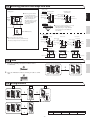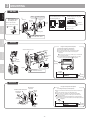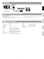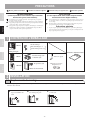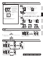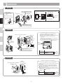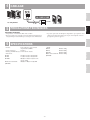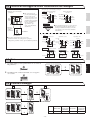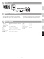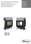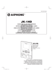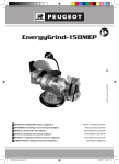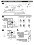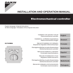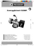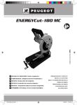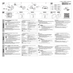
1
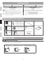
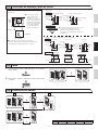
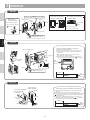
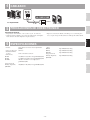
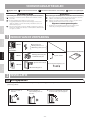
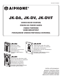
FK1461 Ⓐ P0109YI
JK-DA, JK-DV, JK-DVF
Video door station
Poste de porte vidéo
Video portero
Videodeurpost
Postazione videocitofonica esterna
JK-DA
JK-DVF
Video door station
Poste de porte vidéo
Video portero
Videodeurpost met kunststof
opbouwbehuizing
Postazione videocitofonica
esterna
Vandal-resistant video door station
Portier vidéo résistant au vandalisme
Video portero antivandálico
Videodeurpost met inox antivandalismeinbouwbehuizing
Postazione videocitofonica esterna
resistente agli atti vandalici
JK-DV
Vandal-resistant video door station
Portier vidéo résistant au vandalisme
Video portero antivandálico
Videodeurpost met metalen
antivandalisme-opbehuizing
Postazione videocitofonica esterna
resistente agli atti vandalici
INSTALLATION MANUAL
MANUEL D’INSTALLATION
MANUAL DE INSTALACIÓN
INSTALLATIEHANDLEIDING
MANUALE D'INSTALLAZIONE
Precautions
Prohibition to dismantle the unit
Prohibition on subjecting the unit to Water
WarninG
(negligence could result in injury to people or damage to property.)
1. Do not dismantle or alter the unit. Fire or electric shock could result.
2. Existing wiring such as chime wiring, etc. may contain high voltage AC electricity.
Damage to the unit or electric shock could result. Wiring and installation should be
done by a qualified technician.
3. This unit is not an explosion-proof unit. Do not install or use the unit in locations
that are filled with flammable gas such as oxygen rooms. Fire or an explosion could
result.
1
General Precautions
caution
(negligence could result in death or serious injury.)
Español
Français
English
General Prohibitions
1. Before turning on power, make sure wires are not crossed or shorted. If not, fire or
electric shock could result.
2. Do not install or make any wire terminations while power supply is plugged in. It
can cause electrical shock or damage to the unit.
General Precautions
1. The door station is weather resistant, but do not spray high pressure water on door
station directly. Unit trouble could result.
PacKaGe contents
Mounting screws
Mounting screws x 2
Wood mounting screws x 2
JK-DA
Front panel
Main unit
INSTALLATION MANUAL
Nederlands
JK-DV
Mounting screws (x4)
and anchor bolts (x4)
Special screwdriver
Special screws (x4)
Transparent nameplates x 2
JK-DVF
Italiano
Flush mount back box
2
instaLLation
2-1 Mounting locations
"Do not install video door station in any of the following locations where lighting or the ambient environment could impact the display on the
video monitor due to the characteristics of the door station's camera."
a
Locations subject to direct
sunlight
b
c
Under street lights or door
lights
-2-
Other locations subject to strong
lighting or backlighting conditions
2-2 Mounting positions and image view area
◇ Wide picture
◇ Wide picture
Up/Down
Approx.
1,050 mm
(3' 5")
English
Mounting position
Mounting position
1,300 mm (4' 3")
1,500 mm (5')
Approx. 2,000 mm
Approx. 1,800 mm
(6' 7")
(5'
11")
Unit center
Approx. 1,050 mm (3' 5")
Approx. 1,050 mm (3' 5")
Unit center
Approx. 950 mm
1,500 mm (5') Approx. 750 mm
(3' 2")
1,300 mm (4' 3")
(2' 5")
◆ Objects appear smaller due
to greater distortion in the
surrounding sections compared
to the central section, but a
wider area is displayed.
The display range is a rough
estimation and may change
due to the installation
environment.
500 mm (20")
500 mm (20")
Left/Right
500 mm (20")
Approx. 700 mm (2' 3")
Français
◆ An area over a range of approx. 170°in a 500
mm radius from the camera displays.
(The display range is a rough estimation
and may change due to the installation
environment.)
Approx. 170°
◇ Zoom picture
◇ Zoom picture (when mounting position is 1,500 mm (5'))
Approx. 900 mm (3')
Up/Down
Zoom <Up>
Approx. 2,250 mm
(7' 5")
Zoom <Center>
Approx. 850 mm (2'9")
Unit center
Approx. 1,400 mm
(4' 7")
500 mm (20")
Approx. 1,600 mm
(5' 4")
Approx. 700 mm
(2' 3")
Approx. 1,150 mm
(3' 9")
500 mm (20") 1,500 mm (5')
Left/Right
Zoom <Down>
Approx. 1,850 mm
(6' 1")
Zoom <Left>
Approx. 850 mm
(2' 9")
1,500 mm (5')
Zoom <Center>
Zoom <Right>
500 mm (20")
Approx. 900 mm (3')
500 mm
(20")
Approx.
1,300 mm (4' 3")
Approx. 100 mm (4")
2-3 cable
1
PVC jacket with PE (polyethylene) insulated cable is
recommended.
Italiano
2
2
Nederlands
Approx.
1,300 mm (4' 3")
1,500 mm (5')
Approx. 750 mm
(2'5")
500 mm (20")
500 mm (20")
Approx. 100 mm (4")
Unit center
Unit center
Español
◆ The zoom position can be changed.
(Refer to the master station's operation manual.)
The factory setting is "Center " for Zoom mode.
Never use individual conductors, twisted pair cable or coaxial
cable.
JK-DA
JK-DV
JK-DVF
JK-1MED
JK-1MD
2-4 Wiring distance
M
D
2
JK-DA
JK-DV
4
JK-1MED
JK-1MD
JK-DVF
S
JK-1SD
JK-1HD
A
2
JK-DA
JK-DV
JK-DVF
A
JK-1MED
JK-1MD
A
-3-
Ø 0.65 mm
50 m
22 AWG
165'
Ø 1.0 mm
100 m
18 AWG
330'
3
MountinG
English
JK-DA
① Removing the
main unit from the
mounting frame
Place "
②
Main unit
Français
Remove the main unit.
(Loosen the locking screws.)
③ Mount the main unit on
the mounting frame, and fit
the front panel on.
UP" upwards
1-gang box
Mounting
screws x 2
83.5 mm
(3-5/16")
Flathead
screwdriver
Screwdriver
Front panel
Tighten
Removing the front panel
<Bottom surface>
Main unit
Loosen
Pry off the front panel with
a flathead screwdriver.
Mounting frame
Drainage hole
Español
Do not block the holes.
JK-DV
Using the transparent nameplates
Inserting the transparent nameplates
Nederlands
Vandal-resistant front panel
75 mm
3''
Anchor bolts x 4
150 mm
5-15/16''
Loosen
Italiano
Special
screwdriver
① Remove the vandal-resistant front panel.
② Peel off the protective seals on the plate (both sides).
③ Fill in the name of the resident on the transparent
nameplate.
Be sure to leave 25 mm (1") of white space on the left end
to account for insertion.
④ Insert the filled-in transparent nameplate at the specified
in diagram).
insertion opening (indicated with
To
insertion
opening
Ø 6 mm
Ø 1/4"
Tighten
35 mm
1-3/8"
Drainage hole
Do not block the holes.
25 mm
1"
ABC
To
insertion
opening
JK-DVF
Vandal-resistant front panel
Transparent
nameplate
Special
screwdriver
Using the transparent nameplates
Flush mount
back box
Inserting the transparent nameplates
① Remove the vandal-resistant front panel from the flush mount back
box.
② Peel off the protective seals on the plate (both sides).
③ Fill in the name of the resident on the transparent nameplate.
Be sure to leave 25 mm (1") of white space on the left end to
account for insertion.
④ Insert the filled-in transparent nameplate at the specified insertion
opening on the rear side of the vandal-resistant front panel (indicated
in diagram).
with
110 mm
4-3/8''
180 mm
7-3/32''
25 mm
1"
Tighten Mounting
screws x 4
ABC
45 mm
1-25/32''
-4-
To
insertion
opening
4
WirinG
A1 A2
JK-DV
JK-1MED/1MD
JK-DVF
2
NP: non-polarized
A1
NP
A2
• Operating temperature: -10 C to +60 C (+14 F to +140 F)
• Cleaning: Clean the units with a soft cloth dampened with a neutral household
cleanser. Do not use any abrasive cleaner or cloth.
JK-1MD
• Door station is weather resistant. However, do not spray high pressure water on
door station directly. Unit trouble could result.
Español
sPecifications
• Camera unit:
Complementary metal oxide semiconductor
(CMOS)
525 lines
5 Lux at 50 cm (1'6") distance
JK-DA:
JK-DV:
JK-DVF:
Flush mount back box:
(JK-DVF)
Approx. 190 g (0.42 lbs.)
Approx. 650 g (1.43 lbs.)
Approx. 580 g (1.27 lbs.)
Approx. 450 g (1.0 lbs.)
Italiano
129 (H) x 97 (W) x 35.5 (D) (mm)
5-1/8 (H) x 3-7/8 (W) x 1-9/16 (D) (inches)
JK-DV:
173 (H) x 98 (W) x 29.5 (D) (mm)
6-13/16 (H) x 3-7/8 (W) x 1-3/8 (D) (inches)
JK-DVF:
209 (H) x 135 (W) x exposed area 8 (D) (mm)
8-1/4 (H) x 5-5/16 (W) x 5/16 (D) (inches)
Flush mount back box: 180 (H) x 110 (W) x 45 (D) (mm)
(JK-DVF)
7-3/32 (H) X 4-3/8 (W) X 1-25/32 (D) (inches)
• Weight:
Nederlands
• Scanning lines:
• Minimum subject
illumination:
• Dimensions:
JK-DA:
JK-1MED
tecHnicaL Precautions
technical precautions
6
DOOR
Français
5
English
JK-DA
-5-
PRECAUTIONS
Interdiction de démonter l’appareil Interdiction d’exposer l’appareil à l’eau AVERTISSEMENT
Précautions générales
ATTENTION
(Le non-respect de cet avertissement risque d’entraîner
des blessures graves, voire mortelles.)
(Le non-respect de cet avertissement risque d’entraîner
des blessures ou des dégâts matériels.)
1. Ne démontez pas et ne modifiez pas l’unité. Vous risqueriez de provoquer un
incendie ou un choc électrique.
2. Le câblage existant peut être conducteur d’électricité CA. Ceci peut endommager
l’appareil et provoquer un incendie ou une décharge électrique. Faites réaliser les
opérations de câblage par un technicien qualifié.
3. Cet appareil n’est pas à l’épreuve des explosions. N’installez pas ou n’utilisez pas
l’unité dans des endroits présentant des gaz inflammables, tels que des salles à
oxygène. Un incendie ou une explosion peut survenir.
1. Avant de brancher le bloc d’alimentation, vérifiez que les fils ne sont pas croisés ou
en court-circuit. Dans le cas contraire, cela pourrait provoquer un incendie ou un
choc électrique.
2. Ne réalisez aucune connexion de fil lorsque l’appareil est branché, sous peine de
provoquer une décharge électrique ou d’endommager l’unité.
1
Précautions générales
1. Le poste de porte est protégé contre les intempéries, cependant ne pulvérisez pas
d’eau sous haute pression directement sur le poste de porte. Cela risquerait en effet
de provoquer une panne de l’appareil.
CONTENU DE L’EMBALLAGE
Vis de montage
Vis de montage x 2
Vis de montage à bois x 2
JK-DA
Face avant
Unité principale
Nederlands
Español
Français
English
Mesures générales d’interdiction MANUEL D’INSTALLATION
Vis de montage (x4)
et chevilles (x4)
JK-DV
Tournevis spécial
Vis spéciales (x4)
Etiquettes porte-noms
transparentes x2
Italiano
JK-DVF
Boîtier d’encastrement
2
INSTALLATION
2-1 Emplacements de montage
N’installez pas le portier vidéo aux endroits repris ci-dessous où l’éclairage et l’environnement ambiant pourrait affecter l’affichage sur le
moniteur vidéo intérieur.
a
Endroits directement
exposés à la lumière du
soleil
b
Sous des éclairages publics ou
des éclairages de porte
-6-
c
Autres endroits fortement éclairés ou
à contre-jour
2-2 Positions de montage et zone de vision de l’image
◇ Image plein écran
◇ Image plein écran
Haut/bas
Environ
1 050
mm
Gauche/droite
◆ Une zone de couverture s’affiche, d’environ 170° avec un
rayon de 500 mm à partir de la caméra.
(La plage d’affichage est une estimation brute et peut
varier suite à l’environnement de l’installation.)
Environ 170°
500 mm
Français
◇ Image Zoom
Position de montage 1 500 mm
Position de montage 1 300 mm
Environ 2 000
Environ 1 800
mm
mm
Centre de l’unité
Environ 1 050 mm
Environ 1 050 mm
Centre de l’unité
Environ 950
1 500 mm Environ 750
mm
1 300 mm
mm
500 mm
500 mm
English
◆ Les objets apparaissent plus
petits à cause d’une plus
grande distorsion dans les
sections environnantes par
rapport à la partie centrale,
mais ainsi, une zone plus
grande est affichée.
La plage d’affichage est
une estimation brute et peut
varier suite à l’environnement
d’installation.
Environ 700 mm
◇ Image de zoom (lorsque la position de montage est de 1 500 mm)
Environ 900 mm
Haut/bas
Zoom <Centre>
Zoom <Haut>
Environ 2 250
mm
Environ 850 mm
Environ 1 400
mm
500 mm
500 mm
Environ 1 850
mm
Centre de l’unité
Environ 700
mm
Environ 1 150
mm
1 500 mm
Gauche/droite Zoom <Gauche>
Environ 1 600 mm
Centre de l’unité
1 500 mm
Environ 850 mm
500 mm
Zoom <Centre>
1 500 mm
Zoom <Droite>
Environ 900 mm
500 mm
Environ
1 300 mm
Environ 100 mm
2-3 Câble
1
Italiano
Il est recommandé d’utiliser un câble téléphonique SYT1 9/10ème ou LYT1
8/10ème avec écran.Il est recommandé d’utiliser une gaine en PVC avec un
câble électrique en PE (polyéthylène).
2
2
N’utilisez jamais de conducteurs séparés, un câble à paire torsadée
ou un câble coaxial.
JK-DA
JK-DV
JK-DVF
JK-1MED
JK-1MD
2-4 Longueur de câblage
M
D
2
JK-DA
JK-DV
JK-1MED
JK-1MD
JK-DVF
S
4
JK-1SD
JK-1HD
A
2
JK-DA
JK-DV
JK-DVF
A
JK-1MED
JK-1MD
A
-7-
Ø 0,65 mm
50 m
22 AWG
165’
Nederlands
500 mm
Environ
1 300 mm
Centre de
l’unité
Environ 750 mm
500 mm
Environ 100 mm
Zoom <Bas>
Español
◆ La position du zoom peut être modifiée.
(Cf. Se reporter au manuel d’utilisation du poste maître.)
Le réglage par défaut du mode Zoom est "Centré".
Ø 1,0 mm
100 m
18 AWG
330’
3
MONTAGE
English
JK-DA
① Retirer l’unité
principale de son
étrier
②
Unité principale
Retirez l’unité principale.
(Dévissez les vis de montage).
Français
Placez le “
③ Montez l’unité principale
sur l’étrier et fixez la face
avant.
HAUT”vers le haut
Boîte simple
Vis de
montage x 2
Tournevis à
tête plate
83,5 mm
Tournevis
Face avant
Serrer
Retrait de la face avant
<Surface inférieure>
Unité principale
Desserrer
Soulevez la face avant à
l’aide d’un tournevis plat.
Etrier
Orifice de drainage
Español
N’obstruez pas les orifices.
JK-DV
Utilisation des étiquettes porte-noms transparentes
Insertion des étiquettes porte-noms transparentes
Platine face avant résistant au vandalisme
Nederlands
75 mm
Chevilles x 4
150 mm
Dévisser
Tournevis
spécial
①Retirez la face avant résistant au vandalisme.
②Détachez les joints de protection sur la plaque (les deux côtés).
③Ecrivez le nom du résidant sur l’étiquette porte-nom
transparente.
Veillez à laisser 25 mm d’espace blanc sur le bord gauche
pour prendre en compte l’insertion.
④Insérez l’étiquette porte-nom transparente remplie dans l’ouverture
d’insertion spécifiée (indiquée par un
dans le schéma).
Vers
l’ouverture
d’insertion
Italiano
Ø 6 mm
35 mm
Visser
Orifice de drainage
N’obstruez pas les orifices.
25 mm
ABC
Vers
l’ouverture
d’insertion
JK-DVF
Face avant résistant au vandalisme
Etiquette porte
noms
Utilisation des étiquettes porte-noms transparentes
Boîtier
d’encastrement
Insertion des étiquettes porte-noms transparentes
①Retirez la face avant de la platine résistant au vandalisme du boîtier
d’encastrement.
②Détachez les joints de protection sur la plaque (les deux côtés).
③Ecrivez le nom du résidant sur l’étiquette porte-nom transparente.
Veillez à laisser 25 mm d’espace blanc sur le bord gauche pour
prendre en compte l’insertion.
④Insérez l’étiquette porte-nom transparente remplie dans l’ouverture
d’insertion spécifiée sur le côté arrière de la platine avant antivandale
dans le schéma).
(indiquée par un
110 mm
180 mm
Tournevis
spécial
25 mm
Visser
Vis de
montage x 4
ABC
45 mm
-8-
Vers
l’ouverture
d’insertion
4
CABLAGE
A1 A2
JK-DV
JK-1MED/1MD
JK-DVF
2
NP: non polarisé
A1
NP
PLATINE
JK-1MED
JK-1MD
PRECAUTIONS TECHNIQUES
Précautions techniques
• Température de fonctionnement: Entre -10°C et +60°C
• Nettoyage: Nettoyer les appareils à l’aide d’un chiffon doux imprégné d’un
détergent ménager neutre. N’utilisez pas de détergent ou de chiffon abrasif.
• Le poste de porte résiste aux intempéries. Cependant, ne pas vaporiser de l’eau
à haute pression directement sur un poste de porte. Cela risquerait en effet de
provoquer une panne de l’appareil.
Español
6
A2
Français
5
English
JK-DA
SPECIFICATIONS
JK-DA:
JK-DV:
JK-DVF:
Boîtier d’encastrement:
(JK-DVF)
129 (H) x 97 (L) x 35,5 (P) mm
173 (H) x 98 (L) x 29,5 (P) mm
209 (H) x 135 (L) x 8 (P) de zone
exposée (mm)
180 (H) x 110 (L) x 45 (P) mm
• Poids:
JK-DA:
JK-DV:
JK-DVF:
Boîtier d’encastrement:
(JK-DVF)
Environ 190 g
Environ 650 g
Environ 580 g
Environ 450 g
Nederlands
• Caméra:Semi-conducteur à oxyde de métal
complémentaire (CMOS)
525 lignes
• Lignes de balayage:
•Eclairage minimum du sujet: 5 Lux à 50 cm de distance
• Dimensions:
Italiano
-9-
Precauciones
Français
English
Prohibiciones generales
Prohibición de desmantelar la unidad
Prohibición de exponer la unidad al agua
adVertencia
PrecauciÓn
(no seguir estas instrucciones podría provocar lesiones graves o
incluso la muerte.)
(no seguir estas instrucciones podría causar daños físicos o
materiales.)
1. No desmantele ni modifique la unidad. Existe peligro de incendio o descarga
eléctrica.
2. El alambrado existente, como el cableado de timbre, etc. puede contener
electricidad CA de alta tensión. Existe peligro de daños en el aparato o descargas
eléctricas. El cableado y la instalación debe realizarla un técnico calificado.
3. Esta unidad no es una unidad a prueba de explosiones. No instale ni use la
unidad en lugares llenos de gas inflamable, tales como cuartos de oxígeno. Puede
producirse un incendio o una explosión.
1
Precauciones generales
1. Antes de encender la unidad, asegúrese de que no haya ningún cable cruzado o en
cortocircuito. De lo contrario, podrían producirse incendios o descargas eléctricas.
2. No instale ni realice terminaciones de alambres mientras la unidad esté enchufada,
ya que podría producir descargas eléctricas y dañar la unidad.
Precauciones generales
1. El portero es resistente al ambiente, pero no se rocíe con agua de alta presión sobre
la puerta de forma directa. La unidad podría resultar dañada.
Español
contenido deL PaQuete
Tornillos de montaje
2 tornillos de montaje
2 tornillos de montaje para madera
JK-DA
Nederlands
Panel frontal
Unidad principal
MANUAL DE INSTALACIÓN
Tornillos de montaje (x4)
y pernos de anclaje (x4)
JK-DV
Destornillador especial
Placa de identificación
transparente x 2
Tornillos especiales (x4)
JK-DVF
Italiano
Caja posterior de montaje
empotrado
2
instaLaciÓn
2-1 ubicaciones de montaje
"No instale el video portero en ninguno de los siguientes lugares donde el alumbrado o el medio ambiente podrían impactar la visualización en el
videomonitor debido a las características de la cámara del portero."
a
Lugares expuestos
directamente a la luz del sol
b
c
Bajo una luz de calle o de
portal
- 10 -
Otros lugares expuestos a condiciones
de iluminación excesiva o a contraluz
2-2 Posiciones de montaje y área de visión
◇ Imagen wide
◇ Imagen wide
◆ Los objetos parecen más
pequeños debido a mayor
distorsión en secciones
circundantes en comparación
con la sección central, pero se
visualiza un área más amplia.
El alcance de la visualización
es un cálculo aproximado
y puede cambiar debido al
ambiente de la instalación.
Aprox.
1.050
mm
English
Arriba/Abajo
Posición de montaje 1.500 mm
Posición de montaje 1.300 mm
Aprox. 2.000
Aprox. 1.800
mm
mm
Centro de
Aprox. 1.050 mm
Aprox. 1.050 mm
la unidad
Centro de la unidad
Aprox. 950
1.500 mm
Aprox. 750
mm
1.300 mm
mm
500 mm
500 mm
Izquierda/Derecha
500 mm
Aprox. 700 mm
Français
◆ Se visualiza un área sobre un alcance de aprox. 170°
en un radio de 500 mm desde la cámara.
(El alcance de la visualización es un cálculo
aproximado y puede cambiar debido al ambiente de
la instalación.)
Aprox. 170°
◇ Imagen zoom
◇ Imagen zoom (cuando la posición de montaje es de 1.500 mm)
Aprox. 900 mm
Arriba/Abajo
Zoom <Centro>
Zoom <Arriba>
Aprox. 2.250
mm
Aprox. 850 mm
Aprox. 1.400
mm
500 mm
Izquierda/Derecha Zoom <Izquierda>
Aprox. 1.600 mm
Centro de
la unidad
Aprox. 850 mm
1.500 mm
Zoom <Centro>
Zoom <Derecha>
Aprox. 900 mm
500 mm
Aprox.
1.300 mm
Aprox. 100 mm
2-3 cable
1
Se recomienda usar cables con PE (Polietileno) con revestimiento
aislante de PVC .
Italiano
2
2
Nederlands
500 mm
Aprox.
1.300 mm
Centro de la
unidad
1.500 mm
Aprox. 750 mm
500 mm
500 mm
Aprox. 100 mm
Zoom <Abajo>
500 mm
Aprox. 1.850
mm
Centro de
la unidad Aprox. 700
mm
Aprox. 1.150
mm
1.500 mm
Español
◆ La posición del zoom (acercamiento) puede cambiarse.
(Referirse al manual de funcionamiento del aparato principal.)
La configuración de fábrica del modo Zoom es "Centro".
Nunca emplee conductores individuales, cables de par trenzado
o coaxiales.
JK-DA
JK-DV
JK-DVF
JK-1MED
JK-1MD
2-4 distancia entre cables
M
D
2
JK-DA
JK-DV
4
JK-1MED
JK-1MD
JK-DVF
S
JK-1SD
JK-1HD
A
2
JK-DA
JK-DV
JK-DVF
A
JK-1MED
JK-1MD
A
- 11 -
Ø 0,65 mm
50 m
(22 AWG)
165'
Ø 1,0 mm
100 m
(18 AWG)
330'
3
MontaJe
English
JK-DA
① Retirando la unidad
principal del
cuadro de montaje
②
Coloque "
Unidad principal
Français
Retire la unidad principal.
(Afloje los tornillos de bloqueo.)
③ Monte la unidad principal
en el cuadro de montaje y
coloque el panel frontal.
ARRIBA" hacia arriba
1 caja simple
<superficie inferior>
2 tornillos
de montaje
Destornillador
plano
83,5 mm
Atornillador
Panel frontal
Apretar
Para retirar el panel frontal
Unidad principal
Aflojar
Quite el panel frontal haciendo
palanca con un destornillador plano.
Cuadro de montaje
Orificio de drenaje
Español
No bloquee los orificios.
JK-DV
Cómo usar las placas de identificación transparentes
Para insertar las placas de identificación transparentes
Panel frontal antivandálico
Pernos de anclaje x 4
150 mm
Aflojar
Destornillador
especial
Hacia
abertura de
inserción
Ø 6 mm
Italiano
Nederlands
75 mm
① Retire el panel frontal antivandálico
② Desprenda los sellos de protección en la placa (ambos lados).
③ Anote el nombre del residente en la placa de identificación
transparente.
No olvide dejar 25 mm de espacio en blanco del lado
izquierdo para permitir la inserción.
④ Inserte la placa de identificación transparente con el nombre en la
abertura de inserción especificada (indicada con
en el diagrama).
35 mm
Apretar
Orificio de drenaje
No bloquee los orificios.
25 mm
ABC
Hacia
abertura de
inserción
JK-DVF
Panel frontal antivandálico
Placa de identificación
transparente
Cómo usar las placas de identificación transparentes
Caja posterior de
montaje empotrado
Para insertar las placas de identificación transparentes
① Retire el panel frontal antivandálico de la caja posterior de montaje
empotrado.
② Desprenda los sellos de protección en la placa (ambos lados).
③ Anote el nombre del residente en la placa de identificación transparente.
No olvide dejar 25 mm de espacio en blanco del lado izquierdo para
permitir la inserción.
④ Inserte la placa de identificación transparente con el nombre en la
en el diagrama),
abertura de inserción especificada (indicada con
en la parte posterior del panel frontal antivandálico.
110 mm
180 mm
Destornillador
especial
25 mm
Apretar
4 tornillos
de montaje
ABC
45 mm
- 12 -
Hacia
abertura de
inserción
4
caBLeado
A1 A2
JK-DV
JK-1MED/1MD
JK-DVF
2
NP: no polarizado
A1
NP
A2
JK-1MED
JK-1MD
Precauciones de orden técnico
Precauciones técnicas
• El portero es resistente al ambiente. Sin embargo, no se recomienda que lo
rocíe con agua a alta presión directamente. La unidad podría resultar dañada.
• Temperatura de funcionamiento: -10 °C a +60 °C (+14 °F a +140 °F)
• Limpieza: Limpie las unidades con un paño suave humedecido con limpiador
neutro doméstico. No utilice limpiadores ni paños abrasivos.
Español
6
PUERTA
Français
5
English
JK-DA
esPecificaciones
• Cámara:
JK-DA:
JK-DV:
JK-DVF:
129 (altura) x 97 (ancho) x 35,5 (profundidad) (mm)
173 (altura) x 98 (ancho) x 29,5 (profundidad) (mm)
209 alto x 135 ancho x área expuesta 8 de
profundidad (mm)
Aproximadamente 190 g
Aproximadamente 650 g
Aproximadamente 580 g
Aproximadamente 450 g
180 (altura) x 110 (ancho) x 45 (profundidad) (mm)
Italiano
Caja posterior de
montaje empotrado:
(JK-DVF)
5 Lux a una distancia de 50 cm
• Peso:
JK-DA:
JK-DV:
JK-DVF:
Caja posterior de
montaje empotrado:
(JK-DVF)
Nederlands
• Líneas de exploración:
• Iluminación mínima
de sujeto:
• Dimensiones:
Semiconductor de óxido de metal complementario
(CMOS)
525 líneas
- 13 -
VOORZORGSMAATREGELEN
Français
English
Algemeen verbod Verbod om het toestel te demonteren Verbod om het toestel met water in contact te brengen WAARSCHUWING
OPGELET
(Niet-naleving kan de dood of ernstig lichamelijk letsel veroorzaken.)
(Niet-naleving kan lichamelijk letsel of materiële schade veroorzaken.)
1. Demonteer of verander het toestel niet. Dit kan brand of elektrische schokken
veroorzaken.
2. Bestaande bedrading zoals bedrading van een bel, enz. kan
hoogspanningswisselstroom bevatten. Dit kan beschadiging van het toestel of
elektrische schokken veroorzaken. De bedrading en installatie moeten door een
vakman worden uitgevoerd.
3. Dit toestel is niet bestand tegen explosies. Gebruik of installeer het toestel niet op
plaatsen waar ontvlambaar gas aanwezig is, zoals zuurstofkamers. Dit kan brand of
een explosie veroorzaken.
1
Algemene voorzorgsmaatregelen
1. Controleer of de draden niet gekruist of kortgesloten zijn alvorens de stroom in te
schakelen. Zo niet kan brand of een elektrische schok ontstaan.
2. Sluit niets aan of sluit geen draden af terwijl de voeding is aangesloten. Dit kan
elektrische schokken of schade aan het toestel veroorzaken.
Algemene voorzorgsmaatregelen
1. De buitenpost is weerbestendig, maar spuit geen water onder hoge druk
rechtstreeks op de buitenpost. Dit kan het toestel beschadigen.
Español
INHOUD VAN DE VERPAKKING
Montageschroeven
Montageschroeven x 2
Houtmontageschroeven x 2
JK-DA
Nederlands
Deurpost +
afwerkkader
INSTALLATIEHANDLEIDING
Montageschroeven (x4)
en ankerbouten (x4)
JK-DV
Speciale schroeven (x4)
Italiano
JK-DVF
Speciale sleutel
Doorschijnend naamplaatje (x 2)
Inbouwmontagedoos
2
INSTALLATIE
2-1 Montageplaatsen
Voor een optimale beeldkwaliteit dient de deurpost zodanig te worden opgesteld dat er geen lichtbron komt achter het object dat in beeld wordt
gebracht (tegenlicht).
a
(Lage) zon achter de
bezoeker
b
c
Straatverlichting of
tuinverlichting achter de
bezoeker
- 14 -
Camera in schaduwrijke omgeving
met meer licht op de achtergrond
2-2 Montagestanden en gezichtsveld
◇ Breedbeeld
◇ Breedbeeld
◆ Voorwerpen aan de rand van
het beeld zien er kleiner uit
door de grotere vervorming
t.o.v. het centrale gedeelte
De weergegeven maten zijn
indicatief
Ong.
1.050
mm
English
Omhoog/Omlaag
Montageschroeven 1.500 mm
Montageschroeven 1.300 mm
Ong. 2.000
Ong. 1.800 mm
mm
Midden van
Ong. 1.050 mm
het toestel
Ong. 1.050 mm
Midden van
het toestel
Ong. 950 mm
1.500 mm
Ong. 750
1.300 mm
mm
500 mm
500 mm
Links/Rechts
500 mm
Français
◆ Horizontaal heeft de camera in breedhoekmodus
een bereik van ongeveer 170°.
(De weergegeven waarden zijn benaderend en
kunnen verschillen afhankelijk van de situatie)
Ong. 170°
◇ Ingezoomd
beeld
Ong. 700 mm
◇ Ingezoomd beeld (bij een montagehoogte van 1.500 mm)
Ong. 900 mm
Vertikaal
Zoom <Omhoog>
Ong. 2.250
mm
Zoom <Midden>
Ong. 850 mm
Midden
van het
toestel
Ong. 1.400
mm
500 mm 1.500 mm
Horizontaal
Ong. 1.600 mm
Midden van
het toestel
Ong. 850 mm
1.500 mm
Ong. 700 mm
Ong. 1.150
mm
Zoom <Midden>
Zoom <Rechts>
500 mm
Ong.
1.300 mm
1.500 mm
500 mm
Ong.
1.300 mm
Ong. 900 mm
Ong. 100 mm
2-3 Kabel
1
Kabel met massieve geleiders voorzien van PE (polyethyleen)
isolatie wordt aanbevolen.
Italiano
2
2
Nederlands
500 mm
Midden van
het toestel
Ong. 750 mm
500 mm
Zoom <Links>
Ong. 100 mm
Zoom <Omlaag>
500 mm
Ong. 1.850
mm
Español
◆ De zoompositie kan worden gewijzigd.
(Raadpleeg de bedieningshandleiding van de hoofdpost)
De fabrieksinstelling voor de zoompositie is in centraal.
Gebruik nooit losse geleiders, kabels met gevlochten paren of
coaxkabels.
JK-DA
JK-DV
JK-DVF
JK-1MED
JK-1MD
2-4 Bekabelingsafstand
M
D
2
JK-DA
JK-DV
4
JK-1MED
JK-1MD
JK-DVF
S
JK-1SD
JK-1HD
A
2
JK-DA
JK-DV
JK-DVF
A
JK-1MED
JK-1MD
A
- 15 -
Ø 0,65 mm
50 m
22 AWG
165'
Ø 1,0 mm
100 m
18 AWG
330'
3
MONTAGE
English
JK-DA
① De deurpost van
het montagekader
verwijderen.
Plaats "
②
Deurpost
Draai de schroeven los om het
kader te demonteren
③ Monteer de deurpost terug
op het montagekader, en
plaats er het afwerkkader op.
UP" omhoog
Inbouwdoos
Français
<Onderkant>
Montageschroeven
x2
Platkopschroevendraaier
83,5 mm
Schroevendraaier
Frontpaneel
Vastzetten
Afwerkkader verwijderen
Deurpost
Losdraaien
Haal het frontpaneel eraf met een
platkopschroevendraaier.
Montagekader
Ventilatieopeningen
Español
Blokkeer de gaten niet.
JK-DV
De doorschijnende naamplaatjes gebruiken
De doorschijnende naamplaatjes insteken
Tegen vandalisme
beveiligd frontpaneel
Nederlands
75 mm
Ankerbouten x 4
150 mm
Losdraaien
Speciale
sleutel
Naar de
insteekopening
Ø 6 mm
Italiano
①Verwijder het tegen vandalisme beveiligd frontpaneel.
②Verwijder de beschermende folie van het plaatje (beide zijden).
③Vul de naam van de bewoner in op het doorschijnende
naamplaatje.
Laat links zeker 25 mm vrij om het te kunnen insteken.
④Steek het ingevulde doorschijnende naamplaatje in de
voorgeschreven insteekopening (op het schema aangeduid
).
met
35 mm
Vastzetten
Ventilatieopeningen
Blokkeer de gaten niet.
25 mm
ABC
Naar de
insteekopening
JK-DVF
De doorschijnende naamplaatjes gebruiken
Tegen vandalisme
beveiligd frontpaneel
De doorschijnende naamplaatjes insteken
Inbouwmontagedoos
Doorschijnend
naamplaatje
①Verwijder het tegen vandalisme beveiligd frontpaneel van de
inbouwmontagedoos.
②Verwijder de beschermende folie van het plaatje (beide zijden).
③Vul de naam van de bewoner in op het doorschijnende naamplaatje.
Laat links zeker 25 mm vrij om het te kunnen insteken.
④Steek het ingevulde doorschijnende naamplaatje in de voorgeschreven
insteekopening aan de achterkant van het tegen vandalisme beveiligd
).
frontpaneel (op het schema aangeduid met
110 mm
180 mm
Speciale
sleutel
25 mm
Vastzetten
Montageschroeven
x4
ABC
45 mm
- 16 -
Naar de
insteekopening
4
BEDRADING
A1 A2
JK-DV
JK-1MED/1MD
JK-DVF
2
NP: Niet-gepolariseerd
A1
NP
A2
JK-1MED
JK-1MD
TECHNISCHE VOORZORGSMAATREGELEN
Technische voorzorgsmaatregelen
• De buitenpost is weerbestendig, maar spuit geen water onder hoge druk
rechtstreeks op de buitenpost. Dit kan het toestel beschadigen.
• Bedrijfstemperatuur: -10 °C tot +60 °C (+14 °F tot +140 °F)
• Reiniging: Reinig de toestellen met een zachte doek die bevochtigd is met een
neutraal huishoudelijk reinigingsmiddel. Gebruik nooit schuurmiddelen of een
schuurspons.
Español
6
DEUR
Français
5
English
JK-DA
TECHNISCHE GEGEVENS
CMOS-technologie
NTSC, 525 lijnen
5 Lux op 50 cm afstand
JK-DA:
JK-DV:
JK-DVF:
Inbouwmontagedoos:
(JK-DVF)
129 (H) x 97 (W) x 35,5 (D) (mm)
173 (H) x 98 (W) x 29,5 (D) (mm)
209 (H) x 135 (B) x blootgestelde zone 8 (D) (mm)
180 (H) x 110 (W) x 45 (D) (mm)
• Gewicht:
JK-DA:
JK-DA:
JK-DVF:
Inbouwmontagedoos:
(JK-DVF)
Ong. 190 g
Ong. 650 g
Ong. 580 g
Ong. 450 g
Nederlands
• Camera:
• Videostandaard:
•Minimale verlichting:
• Afmetingen:
Italiano
- 17 -
PRECAUZIONI
Español
Français
English
Divieti generici Divieto di smontare l’unità Divieto di esporre l’unità all’acqua AVVERTENZA
Precauzioni generali
ATTENZIONE
(Il mancato rispetto di quanto indicato potrebbe causare lesioni gravi
o incidenti anche mortali.)
(Il mancato rispetto di quanto indicato potrebbe causare lesioni alle
persone o danni alle cose.)
1. Non smontare, non manomettere l’unità. Pericolo di incendio o di scarica elettrica.
2. I cavi esistenti, per esempio quelli del cicalino, ecc. potrebbero portare elettricità
C.A. ad alta tensione. L’unità potrebbe restare danneggiate oppure si potrebbe
verificare una scarica elettrica. La posa dei cavi e l’installazione devono essere
effettuate da un tecnico qualificato.
3. Quest’unità non è a prova di esplosione. Non installare, non usare l’unità in luoghi
saturi di gas infiammabili, per esempio le camere dell’ossigeno. Ne potrebbe
derivare un incendio o un’esplosione.
1. Prima di accendere l’unità, assicurarsi che i cavi non siano incrociati né in
cortocircuito. In caso contrario, si correrebbe il rischio di un incendio o di scarica
elettrica.
2. Non installare né eseguire terminazioni con cavi se è collegata l’alimentazione.
Tale imprudenza potrebbe causare una scarica elettrica o danneggiare l’unità.
1
contenuto deLLa confezione
Viti di montaggio
Viti di montaggio x 2
Viti di montaggio per legno x 2
JK-DA
Pannello anteriore
Unità principale
Nederlands
Precauzioni generali
1. La postazione videocitofonica esterna è resistente alle intemperie, ma è bene non
spruzzare direttamente sulla postazione getti d’acqua ad alta pressione. L’unità si
potrebbe guastare.
MANUALE
D’INSTALLAZIONE
Viti di montaggio (x4)
e tasselli (x4)
JK-DV
Cacciavite speciale
Viti speciali (x4)
Italiano
JK-DVF
2
Targhette trasparenti x 2
Scatola posteriore per
montaggio a filo
instaLLazione
2-1 Luoghi adatti per il montaggio
"Non installare la postazione videocitofonica esterna in nessuno dei luoghi sotto indicati. luoghi in cui la luce o l’ambiente esterno potrebbero
colpire direttamente il display del monitor per via delle caratteristiche della telecamera della postazione videocitofonica esterna."
a
Luoghi esposti alla luce
solare diretta
b
Sotto ai lampioni
dell’illuminazione pubblica o
alle luci della porta
- 18 -
c
Altri luoghi esposti a forte
illuminazione o a luce di sfondo
intensa
2-2 Posizioni di montaggio ed area di visualizzazione dell’immagine
◇Immagine ripresa nella modalità
grandangolo
Circa 2.000
mm
Circa 1.050 mm
Centro
dell'unità
Circa 950
mm
Circa 1.800
mm
Circa 1.050 mm
1.500 mm
Centro
dell'unità
Circa 750
mm
500 (mm)
1.300 (mm)
500 (mm)
Sinistra/Destra
◆ Viene visualizzata un'area di circa 170° in un raggio
di 500 mm ripresa dall'occhio della telecamera.
(Il campo di visualizzazione indicato è una stima
approssimativa e può variare in base all'ambiente
d'installazione).
Circa 170°
500 (mm)
Circa 700 mm
Français
◇Immagine
ripresa nella
modalità
ingrandimento
◆ Gli oggetti appaiono più
piccoli a causa della maggiore
distorsione nelle parti di
contorno rispetto alla sezione
centrale, ma può essere così
visualizzata un'area più ampia.
Il campo di visualizzazione
indicato è una stima
approssimativa e può
variare in base all'ambiente
d'installazione.
Posizione di montaggio
1.300 mm
Posizione di montaggio
1.500 mm
Su/Giù
English
Circa
1.050
mm
◇ Immagine ripresa nella modalità grandangolo
◇ Immagine ripresa nella modalità ingrandimento (se la posizione di montaggio è di 1.500 mm)
Circa 900 mm
Su/Giù
Ingrandimento <Su>
Circa 2.250
mm
Circa 850 mm
Circa 1.400
mm
Ingrandimento <Centro>
Centro
dell'unità
Centro
Circa 700 mm
dell'unità
Circa 1.150
mm
500 (mm) 1.500 (mm)
Sinistra/Destra Ingrandimento <Sinistra>
1.500 (mm)
500 (mm)
Ingrandimento <Centro>
Centro
dell'unità
Circa 850 mm
1.500 (mm)
500 (mm)
Circa 900 mm
Ingrandimento <Destra>
500 (mm)
Circa
1.300 (mm)
Circa 100 mm
2-3 Cavo
1
Si consiglia l’impiego di una guaina in PVC con cavo isolato in
PE (polietilene).
Italiano
2
2
Nederlands
Circa
1.300 (mm)
Circa 1.600 mm
Circa 750 mm
500 (mm)
Circa 100 mm
Ingrandimento <Giù>
500 (mm)
Circa 1.850
mm
Español
◆ La posizione di ingrandimento può essere variata.
(Consultare il manuale d'uso della postazione principale).
L'impostazione predefinita è "Centro" per la modalità di ingrandimento.
Non utilizzare mai conduttori individuali, cavi con doppini o
cavi coassiali.
JK-DA
JK-DV
JK-DVF
JK-1MED
JK-1MD
2-4 Distanza di cablaggio
M
D
2
JK-DA
JK-DV
4
JK-1MED
JK-1MD
JK-DVF
S
JK-1SD
JK-1HD
A
2
JK-DA
JK-DV
JK-DVF
A
A
JK-1MED
JK-1MD
- 19 -
22 AWG
Ø 0,65 mm (Scala americana
normalizzata)
50 m
165’
Ø 1,0 mm
100 m
18 AWG
(Scala americana
normalizzata)
330’
3
MontaGGio
English
JK-DA
① Rimozione dell'unità
principale dal telaio
di montaggio
②
Posizionare la parte con il simbolo "
Unità principale
UP" verso l'alto
Scatola a muro a 1 modulo
③ Montare l'unità principale sul
telaio di montaggio, ed installare
il pannello anteriore su di questa.
Cacciavite a
lama piatta
83,5 (mm)
Cacciavite
Français
<Superficie inferiore>
Viti di
montaggio x 2
Rimuovere l'unità principale.
(Allentare le viti di bloccaggio).
Per stringere
Rimozione del pannello anteriore
Pannello
anteriore
Per
allentare
Unità
principale
Servendosi di un cacciavite a lama piatta,
staccare il pannello anteriore, facendo leva.
Telaio di montaggio
Foro di scarico
Español
Non otturare i fori.
JK-DV
Uso delle targhette trasparenti
Inserimento delle targhette trasparenti
Pannello anteriore resistente agli atti vandalici
Nederlands
75 mm
Tasselli x 4
150 mm
Per allentare
Cacciavite
speciale
Apertura per
l'inserimento
Ø 6 mm
Italiano
①Rimuovere il pannello anteriore resistente agli atti vandalici.
②Staccare la pellicola protettiva dalla targhetta (sui due lati).
③Scrivere sulla targhetta il nome dell'inquilino dell'abitazione
corrispondente.
Ricordare di lasciare 25 mm di spazio sulla sinistra, per
l'inserimento della targhetta nella sua sede.
④Inserire la targhetta trasparente completa del nome
nel diagramma).
nell'apertura specificata (indicata con
35 mm
Per stringere
Foro di scarico
Non otturare i fori.
25 mm
ABC
Apertura per
l'inserimento
JK-DVF
Pannello anteriore resistente
agli atti vandalici
Targhetta
trasparente
Scatola
posteriore per
montaggio a filo
Uso delle targhette trasparenti
Inserimento delle targhette trasparenti
①Rimuovere il pannello anteriore resistente agli atti vandalici dalla
scatola posteriore per il montaggio a filo.
②Staccare la pellicola protettiva dalla targhetta (sui due lati).
③Scrivere sulla targhetta il nome dell'inquilino dell'abitazione corrispondente.
Ricordare di lasciare 25 mm di spazio sulla sinistra, per l'inserimento
della targhetta nella sua sede.
④Inserire la targhetta trasparente completa del nome nell'apertura
specificata sul retro del pannello anteriore resistente agli atti vandalici
nel diagramma).
(indicata con
110 mm
180 mm
Cacciavite
speciale
25 mm
Per stringere
Viti di
montaggio x 4
ABC
45 mm
- 20 -
Apertura per
l'inserimento
4
caBLaGGio
A1 A2
JK-DV
JK-1MED/1MD
JK-DVF
2
NP: Non polarizzato
A1
NP
A2
JK-1MED
JK-1MD
Precauzioni tecnicHe
Precauzioni tecniche
• Temperatura di funzionamento: da -10 °C a +60 °C (da +14 °F a +140 °F)
• Pulizia: Pulire le unità con un panno morbido imbevuto di detergente neutro
per la casa. Non usare detergenti o panni abrasivi.
• La postazione videocitofonica esterna è resistente alle intemperie. Tuttavia,
è bene non spruzzare direttamente sulla postazione getti d’acqua ad alta
pressione. L’unità si potrebbe guastare.
Español
6
POSTAZIONE
ESTERNA
Français
5
English
JK-DA
sPecificHe
JK-DA:
JK-DV:
JK-DVF:
Scatola posteriore per
montaggio a filo:
(JK-DVF)
129 (A) x 97 (L) x 35,5 (P) (mm)
173 (A) x 98 (L) x 29,5 (P) (mm)
209 (A) x 135 (L) x area esposta 8 (P) (mm)
• Peso:
JK-DA:
JK-DV:
JK-DVF:
Scatola posteriore per
montaggio a filo:
(JK-DVF)
Circa 190 g
Circa 650 g
Circa 580 g
Circa 450 g
Nederlands
• Telecamera:Semiconduttore ad ossido di metallo complementare
(CMOS)
525 linee
• Linee esploratrici:
•Illuminazione minima
del soggetto:
5 Lux ad una distanza di 50 cm
• Dimensioni:
180 (A) x 110 (L) x 45 (P) (mm)
Italiano
- 21 -
Warranty
English
Aiphone warrants thats its products have no material or workmanship defects under normal use conditions for two years after delivery to the end user. Aiphone will perform repair
or replacement free of charge if the product is defective and the warranty applies to the defect. Aiphone reserves unto itself the sole right to make the final decision whether there is
a defect in materials and/or workmanship and whether or not the product is under warranty. This warranty shall not apply to any Aiphone product which has been subject to misuse,
neglect, accident, or to use in violation of instructions furnished, nor extended to units which have been repaired or altered outside of the factory. This warranty does not cover
batteries or damage caused by batteries used in connection with the unit. This warranty only includes carry-in repairs. Any repairs must be made at the shop or place designated in
writing by Aiphone. Aiphone will not be responsible for any costs incurred during on-site service calls. Aiphone will not provide compensation for any loss or damage incurred by
the breakdown or malfunction of its products during use, or for any consequent inconvenience or losses that may result.
The object area of
is the EU.
Garantie
Français
Aiphone garantit que ce produit ne présente pas de défaut matériel ou de fabrication dans des conditions normales d'utilisation pendant les deux années suivant la livraison à
l'utilisateur final. Aiphone en effectuera gratuitement la réparation ou le remplacement si le produit est défectueux et que la garantie s'applique pour le défaut. Aiphone se réserve
le droit exclusif de décider s’il existe ou non un défaut de matière ou de fabrication et si l’appareil est ou non couvert par la garantie. Cette garantie ne s’applique pas à tout
produit Aiphone qui a été l’objet d’une utilisation impropre, de négligence, d’un accident ou qui a été utilisé en dépit des instructions fournies; elle ne couvre pas non plus les
appareils qui ont été réparés ou modifiés en dehors de l’usine. Cette garantie ne couvre pas les piles ni les dégâts infligés par les piles utilisées dans l’appareil. Cette garantie
comprend uniquement les réparations en atelier. Toutes les réparations doivent être réalisées à l'atelier ou au site désigné par écrit par Aiphone. Aiphone décline toute responsabilité
en cas de frais encourus pour les dépannages à domicile. Aiphone n’indemnisera pas le client en cas de pertes, de dommages ou de désagréments causés par une panne ou un
dysfonctionnement d’un de ses produits.
La zone d’application de
est l’UE.
Garantía
Español
Aiphone garantiza que sus productos no tienen defectos de material ni de mano de obra bajo condiciones de uso normal durante dos años tras su entrega al usuario final. Aiphone
realizará la reparación o cambio libre de costo si el producto está defectuoso y la garantía se aplica al defecto. AIPHONE se reserva el derecho de tomar la decisión final de si hay o
no defectos de material y/o de mano de obra, y de si el producto está o no cubierto por la garantía. Esta garantía no cubre ningún producto AIPHONE que haya sido mal utilizado,
descuidado, accidentado, o empleado violando las instrucciones suministradas; la garantía tampoco se aplica a unidades que hayan sido reparadas o alteradas por personas fuera de
la fábrica. Esta garantía no cubre las pilas ni los daños causados por pilas utilizadas asociadas a la unidad. Esta garantía sólo incluye reparaciones acarreadas por el cliente. Todas
las reparaciones deben realizarse en el taller o lugar que Aiphone designe por escrito. Aiphone no se responsabilizará de los gastos generados durante llamadas de servicio. Aiphone
no indemnizará por ninguna pérdida o daño en que se incurra debido a la avería o falla de sus productos durante su uso, ni por ningún inconveniente o pérdida que se produzca
como consecuencia.
El área del objeto
es la EU.
Garantie
Nederlands
Aiphone garandeert dat zijn producten onder normale gebruiksomstandigheden gedurende twee jaar na levering aan de eindgebruiker vrij zijn van materiaal- of fabricagefouten.
Aiphone zal het product kosteloos herstellen of vervangen als het defect is en de garantie van toepassing is op het defect. Aiphone behoudt zich het recht voor om als enige
definitief te bepalen of er al dan niet sprake is van een materiaal- en/of fabricagefout; en of het product nog onder garantie is. Deze garantie geldt niet voor een Aiphone-product dat
is blootgesteld aan verkeerd gebruik, verwaarlozing, een ongeval of verkeerde bediening en evenmin voor toestellen die buiten de fabriek zijn hersteld of gewijzigd. Deze garantie
geldt niet voor batterijen of schade veroorzaakt door batterijen die in het toestel zijn gebruikt. Deze garantie geldt uitsluitend voor herstellingen die worden ingeleverd en opgehaald
door de klant. Alle herstellingen moeten worden uitgevoerd in de winkel of op de plaats die schriftelijk is aangeduid door Aiphone. Kosten die gepaard gaan met herstellingen ter
plaatse kunnen niet worden verhaald op Aiphone. Er kan geen schadeloosstelling van Aiphone worden geëist voor enig verlies of schade als gevolg van een defect of storing tijdens
het gebruik van zijn producten, of voor enig ongemak of verlies dat hieruit voortvloeit.
Het toepassingsgebied van
is de EU.
Garanzia
Italiano
La Aiphone garantisce che i suoi prodotti saranno privi di difetti nei materiali o nella lavorazione, in condizioni di utilizzo normali, per un periodo di due anni dalla consegna
all’utente finale. La Aiphone eseguirà la riparazione o la sostituzione gratuita del prodotto qualora tale prodotto debba risultare difettoso e la garanzia sia applicabile al difetto
rilevato. La Aiphone si riserva il diritto esclusivo di stabilire in via definitiva se sono presenti difetti nei materiali e/o nella lavorazione e se il prodotto è coperto dalla garanzia
oppure no. La presente garanzia non è applicabile ad alcun prodotto Aiphone che sia stato sottoposto ad uso improprio, negligenza, incidente, o che sia stato utilizzato in violazione
alle istruzioni fornite, né può essere estesa alle unità che sono state riparate o manomesse al di fuori della fabbrica. Questa garanzia non copre le batterie né i danni causati dalle
batterie usate in connessione con l’unità. Questa garanzia copre solo le riparazioni del prodotto consegnato presso il punto designato. Le eventuali riparazioni devono essere eseguite
presso l’officina o il luogo designato per iscritto dalla Aiphone. La Aiphone non potrà essere ritenuta responsabile di eventuali costi sostenuti in caso di chiamata per l’assistenza
sul posto. La Aiphone non offrirà alcun compenso per gli eventuali danni o perdite subiti a causa della rottura o del guasto dei suoi prodotti durante l’uso, o per qualsiasi disagio o
perdita conseguente che si dovesse verificare.
L’area oggetto del
è l’UE.
- 22 -
This equipment has been tested and found to comply with the limits for a Class B digital device, pursuant to Part 15 of the FCC Rules. These limits are designed to provide
reasonable protection against harmful interference in a residential installation. This equipment generates, uses, and can radiate radio frequency energy, and if not installed and
used in accordance with the instructions, may cause harmful interference to radio communications. However, there is no guarantee that interference will not occur in a particular
installation. If this equipment does cause harmful interference to radio or television reception, which can be determined by turning the equipment off and on, the user is encouraged
to try to correct the interference by one or more of the following measures:・Reorient or relocate the receiving antenna・Connect the equipment into an outlet on a circuit different
from that to which the receiver is connected. Increase the separation between the equipment and receiver.・Consult the dealer or an experienced radio/TV technician for help.
- 23 -
http://www.aiphone.com/
AIPHONE CO., LTD., NAGOYA, JAPAN
AIPHONE CORPORATION, BELLEVUE, WA, USA
AIPHONE S.A.S., LISSES-EVRY, FRANCE
Printed in Thailand