1
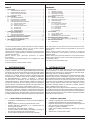
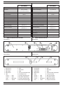
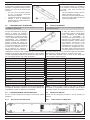
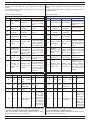
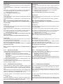
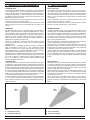
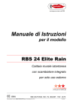
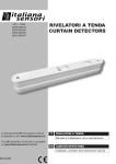
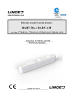
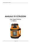
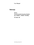
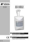
ART. / ITEM:
8032-ISR023
8033-ISR024
RILEVATORI A TENDA UNIVERSALI
UNIVERSAL CURTAIN DETECTORS
IT
RILEVATORI A TENDA UNIVERSALI
Manuale di installazione, uso e manutenzione
EN
UNIVERSAL CURTAIN DETECTORS
Installation, operation and maintenance manual
MADE IN ITALY
- Istruzioni originali -
- Translation of the original instructions (original instructions in Italian) -
INDICE
CONTENTS
1.INTRODUZIONE................................................................................................. 2
1.1 CARATTERISTICHE GENERALI............................................................ 2
1.2 CARATTERISTICHE TECNICHE............................................................ 3
1.3 IDENTIFICAZIONE DELLE PARTI.......................................................... 3
1.4 DOTAZIONI DI SERIE............................................................................. 4
2.INSTALLAZIONE............................................................................................... 4
2.1 AVVERTENZE GENERALI...................................................................... 4
2.2 MONTAGGIO DEL RILEVATORE........................................................... 4
2.3 CABLAGGIO DEL RILEVATORE ........................................................... 5
2.4 CONFIGURAZIONE DEL RILEVATORE................................................. 5
2.4.1 Descrizione dei DIP-switch........................................................... 5
2.4.2 Descrizione dei LED..................................................................... 7
2.4.3 Installazione interna/esterna........................................................ 7
2.4.4 Funzione CWS® ........................................................................... 8
2.4.5 Sensibilità PIR.............................................................................. 8
2.4.6 Antimascheramento..................................................................... 8
3. PRINCIPI DI FUNZIONAMENTO....................................................................... 9
3.1 INSTALLAZIONE TIPICA........................................................................ 9
3.2 TARATURA DEL SENSORE................................................................. 10
3.3 DETERMINAZIONE AREA DI COPERTURA........................................ 10
4. MANUTENZIONE E VERIFICHE PERIODICHE.............................................. 11
4.1 PULIZIA ESTERNA DEL RILEVATORE................................................ 11
5. SMALTIMENTO E ROTTAMAZIONE............................................................... 11
5.1 DISINSTALLAZIONE............................................................................. 11
1.INTRODUCTION................................................................................................ 2
1.1 GENERAL FEATURES........................................................................... 2
1.2 TECHNICAL FEATURES........................................................................ 3
1.3 PARTS IDENTIFICATION....................................................................... 3
1.4 STANDARD EQUIPMENT....................................................................... 4
2.INSTALLATION.................................................................................................. 4
2.1 GENERAL PRECAUTIONS.................................................................... 4
2.2 INSTALLING THE DETECTOR............................................................... 4
2.3 DETECTOR WIRING ............................................................................. 5
2.4 DETECTOR SET-UP............................................................................... 5
2.4.1 DIP-switches configuration........................................................... 5
2.4.2 Description of the LEDs................................................................ 7
2.4.3 Outdoor/indoor Installation........................................................... 7
2.4.4CWS® feature............................................................................... 8
2.4.5 PIR sensibility............................................................................... 8
2.4.6Antimasking.................................................................................. 8
3. UNIT FEATURES............................................................................................... 9
3.1 TYPICAL INSTALLATION........................................................................ 9
3.2 SENSOR SETTING............................................................................... 10
3.3 DETERMINING THE DETECTION AREA............................................. 10
4. MAINTENANCE AND PERIODIC CHECKS.................................................... 11
4.1 CLEANING THE EXTERNAL PART OF THE DETECTOR................... 11
5. DISPOSAL AND SCRAPPING......................................................................... 11
5.1DISMANTLING...................................................................................... 11
Le informazioni riportate in questo manuale sono state compilate
con cura, tuttavia Italiana Sensori non può essere ritenuta
responsabile per eventuali errori e/o omissioni.
Italiana Sensori si riserva il diritto di apportare in ogni momento, e
senza preavviso, miglioramenti e/o modifiche ai prodotti descritti
nel presente manuale.
Italiana Sensori pone particolare attenzione al rispetto
dell’ambiente.
Tutti i prodotti ed i processi produttivi sono progettati con criteri
di eco-compatibilità.
Il presente articolo è stato prodotto in Italia.
The informations in this manual have been issued with care,
anyway Italiana Sensori will not be responsible for any errors or
omissions.
Italiana Sensori reserves the rights to improve or modify the
products described in this manual at any times and without
advance notice.
Italiana Sensori pays particular attention to environment respect.
Each product and each process have been designed with ecocompatibility criteria.
This product has been made in Italy.
1.INTRODUZIONE
1.INTRODUCTION
I rilevatori serie 8032 e 8033 sono stati sviluppati per la protezione
di porte e finestre; essi sono rappresentativi del più alto livello
tecnologico fra i rilevatori anti intrusione a tripla tecnologia gestiti
da microprocessore. Il rilevatore è stato progettato per essere
utilizzato con qualsiasi sistema via radio e qualsiasi protocollo
di trasmissione. Il profilo snello rende possibile l’installazione
tra tapparelle/persiane e finestre. Il rilevatore è composto
da due sensori ad infrarosso ed una microonda a 24 GHz;
l’antimascheramento è stato progettato utilizzando sensori ad
IR attivi che, attraverso le lenti di Fresnel, hanno la capacità di
rilevare ostacoli volontariamente apposti sulla lente stessa per
impedire il rilevamento (spray, nastro adesivo, carta ecc.).
Utilizzando la funzione WIN (Wired Interface Network) è possibile
alimentare il dispositivo attraverso l’alimentazione principale,
mantenendo la Microonda sempre accesa ed avendo dunque le
stesse prestazioni di un rilevatore filare; tramite la funzione WIN
è inoltre possibile eliminare l’inibizione dopo la prima rilevazione.
The 8032 and 8033 series detectors have been developed
for the protection of doors and windows; they represent the
highest level of technology for microprocessor-controlled tripletechnology intrusion prevention detectors.
The detector has been developed to be combined with any radiobased system and any transmission protocol. The thin profile
offers installation between roller shutters/shutters and windows.
The detector consist of two infra-red sensors and one 24 GHz
microwave; the anti-masking is designed using active IR sensors
which, through Fresnel lenses, have the capacity to detect
obstacles voluntarily affixed on the lens to prevent detection
(spray, adhesive tape, paper, etc.).
Using the WIN function (Wired Interface Network) it is possible
to power the devices from the mains, keeping the Microwave on
and therefore offering the same performance as a wired detector;
through the WIN function it is also possible to eliminate inhibition
mode after the first detection.
1.1
1.1
•
•
•
•
•
•
2
CARATTERISTICHE GENERALI
Contenitore in policarbonato e lenti di Fresnel resistenti ai
raggi UV.
Design estetico e meccanico particolarmente curato.
Scheda elettronica alloggiata in un compartimento ad
elevato grado IP (IP55).
Conforme alle norme EN 50131-1 grado 3.
Funzione CWS® (Cross Walking Sensibility): permette di
discriminare la direzione di attraversamento.
Funzione WIN: alimentazione tramite rete principale.
•
•
•
•
•
•
GENERAL FEATURES
Casing in polycarbonate and Fresnel lenses UV resistant.
Carefully developed aesthetic and mechanical design .
Electronic board built-in in a compartment matching with the
base, provided of a sealing gasket (IP55).
EN 50131-1 grade 3 compliant.
CWS® (Cross Walking Sensibility): to identify the crossing
direction.
WIN function: power from the mains.
1.2
CARATTERISTICHE TECNICHE
1.2
TECHNICAL FEATURES
8032-ISR023
8033-ISR024
8032-ISR023
8033-ISR024
Alimentazione
2,35 ÷15 Vcc
Consumo
Power supply
2.35 ÷15 Vdc
10 µA stand-by
18 mA rilevazione
32 mA consumo massimo
Current consumption
Banda K
Microwave frequncy
Frequenza microonda
10 µA stand-by
18 mA detection
32 mA maximum consumption
K Band
Contatti di allarme, tamper,
mascheramento
MOS FET relay
NC-NO
Alarm, masking, tamper contacts
Copertura rilevazione
Vedere par. 3.3
Motion detection coverage
MICROSWITCH
Antitamper function
Funzione antimanomissione
Tempo di allarme
1s
IR attivi
Antimasking
4
Signal LEDs
LED di segnalazione
Grado di protezione contenitore
See par. 3.3
MICROSWITCH
Alarm time
1s
Antimascheramento
MOS FET relay
NC-NO
Active IRs
4
Enclosure degree of protection
IP 55
IP 55
Classe ambientale
Classe III
(EN 50131-1)
Environmental classification
Class III
(EN 50131-1)
Grado di sicurezza
Grado 3
(EN 50131-1)
Security grading
Grade 3
(EN 50131-1)
Contenitore
Policarbonato resistente UV
Temperatura di esercizio
-25 °C ÷ +50 °C
Dimensioni vano trasmettitore
90x23x33 mm
Dimensioni esterne
256 x 34 x 41 mm
Peso
1.3
Casing
UV resistant polycarbonate
Operating temperature
-25 °C ÷ +50 °C
Transmitter compartment
dimensions
90x23x33 mm
External dimensions
256 x 34 x 41 mm
Weight (g)
150 g
IDENTIFICAZIONE DELLE PARTI
1.3
Vista interna
150 g
PARTS IDENTIFICATION
Internal view
10
11
12
13
14
CWS
9
Fig. 1
Vista esterna
External view
6
5
7
8
Fig. 2
1
DIP-switch B
6PIR1
1
DIP-switch B
6PIR1
2
DIP-switch A
7Microonda
2
DIP-switch A
7Microwave
3
PIR Trimmer
8PIR2
3
PIR Trimmer
8PIR2
4
MW Trimmer
9
4
MW Trimmer
9
5LED:
Vano per trasmettitore radio
10 Connettore 12 vie
5LEDs:
Radio transmitter compartment
10 12-way connector
Verde1 ˃
PIR1
11 Trimmer regolazione PIR
Green1 ˃
PIR1
11 PIR control trimmer
Verde2 ˃
PIR2
12 Dip-Switch impostazioni
Green2 ˃
PIR2
12 Dip-Switch settings
Microonda
13 Trimmer regolazione MW
Yellow ˃
Microwave
13 MW control trimmer
Allarme
14 Microswitch antisabotaggio
Red
Alarm
14 Tamper microswitch
Giallo
˃
Rosso ˃
˃
3
1.4
1
2
3
4
DOTAZIONI DI SERIE
1.4
N° 1 rilevatore a tenda
N° 1 kit elementi di fissaggio
N° 1 manuale
N° 1 cavo di collegamento
con connettore
STANDARD EQUIPMENT
1
2
3
4
1
No 1 curtain detectors
No 1 fastening component kit
No 1 manual
No 1 connection cable with
connector
3
2
4
Fig. 3
2.INSTALLAZIONE
2.INSTALLATION
2.1
2.1
AVVERTENZE GENERALI
GENERAL PRECAUTIONS
Prima dell’installazione verificare le seguenti condizioni:
• la parete non deve presentare avvallamenti o sporgenze
eccessive;
• evitare il posizionamento del rilevatore vicino a fonti di
calore o alla luce diretta del sole;
• evitare la riflessione dell’energia elettromagnetica su ampie
superfici quali, ad esempio, specchi, pareti metalliche, etc.;
• evitare di puntare il rilevatore su lampade fluorescenti o
comunque di porlo nelle immediate vicinanze delle stesse.
Il rilevatore a tenda può essere installato in ambiente esterno
riparato (non completamente esposto ad agenti atmosferici) o
interno in condizioni estreme (secondo quanto prescritto dalla
normativa EN 50131-1 nella classe ambientale III).
Before starting the installation, make sure that:
• the wall does not have any pronounced depressions or
protrusions;
• avoid to fix the detectors near to heat sources or at direct
sunlight;
• avoid electromagnetic energy reflection on wide surfaces
such as mirrors, metal walls, etc.;
• avoid to fix the detector in front of fluorescent lamps or in
proximity of them.
The detector can be installed in a sheltered outdoor environment
(not fully exposed to the elements) or indoors in extreme
conditions (in compliance with EN 50131-1 in environmental
class III).
2.2
2.2
MONTAGGIO DEL RILEVATORE
Le seguenti operazioni devono essere effettuate da personale
qualificato e specializzato.
INSTALLING THE DETECTOR
The following operations must be carried out by qualified and
specialist personnel.
•
Con l’uso di un cacciavite svitare le
4 viti V1 e rimuovere il coperchio A.
•
Use a screwdriver to unscrew the 4
screws V1 and remove the lid A.
•
Sulla parete praticare 2 fori B
utilizzando un utensile adeguato ed
installare i tasselli in dotazione.
•
Make 2 holes B in the wall using an
appropriate tool and insert the plugs
supplied.
•
Applicare le due guarnizioni adesive
E sul fondo, nelle apposite sedi.
•
Apply the two adhesive seals (E) in
place on the bottom.
•
Posizionare la base C del rilevatore
sulla parete (in corrispondenza dei
fori B) e fissare con le viti V2 (in
dotazione).
•
Position the base C of the detector
on the wall (in line with the holes
B) and attach it with the screws V2
(supplied).
ATTENZIONE! Per garantire il
grado IP55 è necessario lasciare
montata la guarnizione (D) presente
nella guida interna della base.
•
•
B
B
E
C
E
D
V2
Cablare, secondo le proprie
necessità, il modulo trasmettitore.
Inserirlo nell’apposito vano presente
all’interno della camera stagna.
IMPORTANT! IP55 is guaranteed
by leaving the gasket (D) fitted in the
inner guide of the base.
V2
V1
•
Wire, as needed, the transmitter
module. Place it inside the relative
compartment contained inside the
sealed chamber.
•
Finally, replace the lid A and
fasten with the screws previously
removed V1.
A
V1
A fine operazione, riposizionate il
coperchio A e fissare con le viti V1
precedentemente svitate.
Fig. 4
A Coperchio con scheda rilevatore
B Fori di fissaggio
C Base del rilevatore
DGuarnizione
V1 Viti di chiusura (n° 4)
V2 Viti di fissaggio a muro
X Guarnizioni adesive (n°2)
4
A Cover with detector board
B Fixing holes
C Detector base
DGasket
V1 Screws (No 4)
V2 Wall fixing screws
X Adhesive seals (No 2)
Se lo spazio a disposizione per inserire il
modulo radio non è sufficiente, è possibile
effettuare i collegamenti elettrici facendo
uscire il cavo a 12 vie dal coperchio del
rilevatore.
• Con l’uso di un cacciavite praticare
un foro sul coperchio, servendosi
della parte pre-tagliata.
• Inserire la guarnizione o-ring nel foro.
• Passare il cavo di collegamento
all’interno del foro e della guarnizione
appena applicata.
2.3
If there is not enough available space to
put in the radio module, it is possible to
set up electrical connections by having
the 12-way cable feed out from the
detector lid.
• Use a screwdriver to make a hole on
the lid, using the pre-cut area.
• Place the o-ring seal inside the hole.
• Pass a connecting cable into the hole
and newly-applied seal.
Fig. 5
CABLAGGIO DEL RILEVATORE
2.3
DETECTOR WIRING
Le seguenti operazioni devono essere effettuate da personale
qualificato e specializzato.
The following operations must be carried out by qualified and
specialist personnel.
Non può essere definito un cablaggio
univoco in quanto, per rendere il
rilevatore universale è stato lasciato
all’installatore il compito di collegare
i cavi in base alle necessità e alle
caratteristiche del trasmettitore
utilizzato. Verificare se il trasmettitore
gestisce ingressi NA oppure NC
(riferirsi al manuale del trasmettitore
che si intende installare). Il rilevatore
è dotato di un apposito cavo a 12
fili da utilizzare per realizzare i
collegamenti. Dopo aver effettuato i Fig. 6
collegamenti al modulo radio, collegare il cavo con la scheda
elettronica, servendosi degli appositi connettori, come mostrato
in figura. Nella tabella seguente sono illustrate le corrispondenze
tra i colori dei fili del cavo e le uscite del rilevatore.
To make the detector universal it is
not possible to define a single wiring
set-up, accordingly, the installation
technician
is
responsible
for
connecting the cables based on the
demands and characteristics of the
selected transmitter. Check whether
the transmitter controls NO or NC
inputs (refer to the manual of the
transmitter that you intend to install).
The detector is equipped with a 12wire cable, which is used to set up the
connections.When the connections to
the radio module are set up, connect the cable to the electronic
board using the relative connectors, as shown in the figure.
The table below illustrates how to match up the cable wire
colours and the detector outputs.
DESCRIZIONE
COLORE
DESCRIPTION
COLOUR
ALIMENTAZIONE BATTERIA
ROSSO
BATTERY SUPPLY
RED
MASSA
NERO
EARTH
BLACK
ALLARME NC
MARRONE
NC ALARM
BROWN
ALLARME C
ROSA
C ALARM
PINK
ALLARME NA
ARANCIO
NA ALARM
ORANGE
ANTIMASK NC
GIALLO
NC ANTIMASK
YELLOW
ANTIMASK C
VERDE
C ANTIMASK
GREEN
ANTIMASK NA
BLU
NA ANTIMASK
BLUE
TAMPER NC
BIANCO
NC TAMPER
WHITE
TAMPER C
GRIGIO
C TAMPER
GREY
TAMPER NA
VIOLA
NA TAMPER
PURPLE
ALIMENTAZIONE FILARE (WIN)
AZZURRO
WIRE POWER SUPPLY (WIN)
LIGHT BLUE
NOTA: per garantire il controllo dello stato di carica della batteria,
si onsiglia di alimentare il rilevatore con la stessa batteria del
trasmettitore e quindi non utilizzarne una dedicata.
NOTE: in order to ensure control of the state of charge of
the battery, it is advisable to feed the detector with the same
transmitter battery and therefore do not use one dedicated.
2.4
2.4
CONFIGURAZIONE DEL RILEVATORE
DETECTOR SET-UP
Per una corretta configurazione seguire le istruzioni di questo
paragrafo.
Please use this paragraph procedure to set-up correctly the
detector.
2.4.1
2.4.1
Descrizione dei DIP-switch
DIP-switches configuration
Fig. 7
5
In modalità a batteria, le variazioni di configurazione dei dip
switch hanno effetto dopo la prima rilevazione che genera
allarme.
In modalità WIN le variazioni di configurazione dei dip switch
hanno effetto immediato.
In battery-operation mode, the dip switch configuration variations
have an effect following the first detection that generates an
alarm.
In WIN mode the dip switch configuration variations have an
immediate effect.
Vedere la seguente tabella.
See following table.
Tab. 1
DIP
Tab. 1
OFF
ON
Annotazioni
DIP
E’ possibile avere i
LED sempre accesi solo in modalità
WIN.
1
LED sempre
LED spenti .
accesi.
2
AND/OR delle AND/OR delle Vedi tabella
tecnologie.
tecnologie.
guente.
se-
3
AND/OR delle AND/OR delle Vedi tabella
tecnologie.
tecnologie.
guente.
se-
4
Funzione Anti- Funzione Antimask disattiva. mask attiva.
5
Discrimina il verso
di attraversamento:
Funzione CWS Funzione CWS
il verso di attraverdisattiva.
attiva.
samento viene definito tramite il DIP 6.
6
Sensibile all’at- Verificare che il DIP
Sensibile all’attraversamento 2 e 3 siano in potraversamento
in direzione op- sizione compatibiin
direzione
posta a quella le con la funzione
della freccia.
della freccia.
CWS.
7
Tempo di inibi- Tempo di inibi- Selezionabile solo
zione di 3 mi- zione di 30 se- con funzionamento
nuti
condi.
a batteria
8
Selezionabile solo
con funzionamento
Inibizione atInibizione attiva a batteria. Se “ON”
tiva dopo un
dopo due eventi saranno necessari
eveneto di aldi allarme
due eventi di allarlarme
me per far inibire il
rilevatore
Notes
It is only possible to
have the LEDs on
all the time in WIN
mode.
1
LEDs enabled.
LEDs disabled.
2
Technology
AND/OR.
Technology
AND/OR.
See table below.
3
Technology
AND/OR.
Technology
AND/OR.
See table below.
4
Anti-mask funAnti-mask function deactivaction activated.
ted.
5
Discriminate
the
crossing direction:
CWS function CWS function
the crossing direcdeactivated
activated.
tion is defined by
DIP 6.
6
Sensitive
to Make sure that the
Sensitive
to
crossing in the DIP 2 and 3 are in a
crossing in the
opposite direc- position compatible
direction of the
tion of the ar- with the CWS funarrow.
row.
ction.
7
Inhibition time Inhibition time Selectable only in
of 3 minutes.
of 30 seconds. battery mode
8
Selectable only in
battery mode. If
Inhibition acti- Inhibition acti- “ON” is selected,
vated after an vated after two two events of alaralarm event
alarm events
ma will be necessary for inhibit the
detector.
FUNCTION
DIP 2
DIP 3
-
A
OFF
OFF
PIR 1
PIR 2
MW
(PIR 1 AND
MW) OR (PIR NO
2 AND MW)
-
B
OFF
ON
(PIR 1 AND
MW) OR (PIR NO
2 AND MW)
-
PIR 1
PIR 2
-
C
ON
OFF
PIR 1
PIR 2
-
FUNZIONE
DIP 2
DIP 3
A
OFF
OFF
PIR 1
PIR 2
MW
B
OFF
ON
C
ON
OFF
ON
ON
RILEVAZIONE
CWS
AND
AND OK
AND
OK
PIR 1 OR PIR
NO
2 OR MW
Annotazioni
Funzione
attiva solo
in modalità
WIN. In funzionamento
a batteria
la funzione
diventa PIR
1 OR PIR 2
Trimmer MW e Trimmer IR: impostano la sensibilità delle
rispettive tecnologie (distanza MIN. - distanza MAX.).
Dopo ogni regolazione del trimmer, attendere circa un minuto
prima di effettuare le prove di rilevazione.
6
ON
Tab. 2
Tab. 2
D
OFF
D
ON
ON
DETECTION
CWS
AND
AND OK
AND
OK
PIR 1 OR PIR
NO
2 OR MW
Notes
-
This
function is only
active
in
WIN mode.
In batteryoperation
mode, the
function becomes PIR
1 OR PIR 2
Trimmer MW and Trimmer IR: set the related sensibility’s
function (MIN distance - MAX distance).
Every time the trimmer is adjusted, wait approximately one minute before running detection tests.
Descrizione della funzione (rif. Tab. 2)
Funzione: A.
Uscita allarme attiva solo quando tutte e tre le tecnologie rilevano la presenza.
Funzione utilizzabile in modalità WIN e in funzionamento a batteria.
Con questa configurazione sono possibili, e quindi attivabili tramite gli specifici dip switch, le seguenti funzioni avanzate:
• CWS (DIP-switch n° 5 e 6);
Nota: consigliata in ambienti esterni.
Function description (ref. Tab. 2)
Function: A.
The alarm will be activated when all the 3 sensors detect the
intrusion.
This function can be used in WIN mode and battery-operation.
The following advanced features can be set up and therefore
activated from the specific dip switches in this configuration:
• CWS (DIP-switch n° 5 and 6);
Note: recommended for the external environment.
Funzione: B.
Uscita allarme attiva quando la MW e qualsiasi dei due PIR rilevano la presenza.
Funzione utilizzabile in modalità WIN e in funzionamento a batteria.
Nota: non consigliata in ambienti particolarmente ostili.
Nota: in questa configurazione non è possibile attivare la
funzione CWS.
Function: B.
Alarm output active when the MW and any one of the two PIR
detect a presence.
This function can be used in WIN mode and battery-operation.
Funzione: C.
Uscita allarme attiva quando entrambi i PIR rilevano la presenza;
non viene gestita la MW.
Funzione utilizzabile in modalità WIN e in funzionamento a batteria.
Con questa configurazione sono possibili, e quindi attivabili tramite gli specifici dip switch, le seguenti funzioni avanzate:
• CWS (DIP-switch n° 5 e 6);
Nota: la rilevazione della MW non ha influenza sulle prestazioni del sensore.
Nota: non consigliata in ambienti particolarmente ostili.
Function: C.
The alarm will be activated when both the 2 PIR detect the instrusion. MW disabled.
This function can be used in WIN mode and battery-operation.
Funzione: D.
Uscita allarme attiva quando una sola tecnologia (uno dei due
PIR oppure la MW) rileva la presenza.
Funzione attiva solo in modalità WIN. In funzionamento a batteria la funzione diventa PIR 1 OR PIR 2.
Nota: non utilizzabile in applicazioni esterne o in ambienti
particolarmente ostili.
Function: D.
Active alarm output when a single technology (one of the two
PIR or the MW) detects the presence.
This function is only active in WIN mode. In battery-operation
mode, the function becomes PIR 1 OR PIR 2.
Note: this cannot be used in outdoor applications or in particularly hostile environments.
Nota: in questa configurazione non è possibile attivare la
funzione.
Note: in this configuration it is not possible to activate the
function.
2.4.2
2.4.2
Descrizione dei LED
Note: dissuaded from hostile environment.
Note: in this configuration it is not possible to activate the
CWS function.
The following advanced features can be set up and therefore
activated from the specific dip switches in this configuration:
• CWS (DIP-switch n° 5 and 6);
Note: MW detection does not influence the detector.
Note: dissuaded from hostile environment.
Description of the LEDs
I LED segnalano l’attivazione del singolo sensore come di seguito riportato (vedi anche la figura par.1.3):
• LED rosso: si accende ad ogni rilevazione di allarme.
• LED giallo: si accende ogni qualvolta la microonda rileva
una presenza.
• LED verde: si accende ogni qualvolta uno dei due sensori
PIR rileva una presenza.
Quando il rilevatore rileva un tentativo di mascheramento i quattro LED lampeggiano lentamente.
I LED del rilevatore possono essere attivati o disattivati utilizzando il DIP-switch A1 (v. Tab. 1).
This LEDs show activation of the different sensors according to
the following (see also the figure in par.1.3):
• Red LED: transmission for alarm.
• Yellow LED: microwave indicator LED.
• Green LED: PIR sensor indicator LED.
When an antimasking alarm is activated all LEDs will blink slowly.
The LEDs of the detector can be activated or deactivated using
the DIP-switches A1 (see Tab. 1).
2.4.3
2.4.3
Installazione interna/esterna
Outdoor/indoor Installation
Nell’installazione in ambienti interni dovrebbero essere evitate
posizioni vicino (distanza minore di 1 metro) a trasmettitori/ricevitori di radiofrequenza (reti Wi-fi, ripetitori televisivi o altri apparati).
Nell’installazione in ambienti esterni deve essere evitata l’installazione in posizioni in cui le lenti del rilevatore vengano investite
dalla luce solare diretta (rif. installazione B - Fig. 11).
In the internal environment should be avoided sites near (less
than 1 meter) radio-frequency transmitter/receiver (e.g. Wi-fi router, TV transmitter).
In the external environment should be avoided sites in which the
detector lenses are directly exposed to the sunlight (ref. installation B - Fig. 11).
In ambiente esterni è raccomandata la seguente impostazione
dei DIP-switch:
• 2: OFF; 3: OFF.
Effettuare una prova di portata per regolare la sensibilità microonda e la sensibilità PIR, utilizzando il MW Trimmer (girare in
senso orario per max sensibilità) ed il PIR Trimmer.
In outdoor environment the following DIP-switches configuration
is recommended:
• 2: OFF; 3: OFF.
Perform a range test to adjust the microwave and PIR sensitivity
using the MW Trimmer (turn clockwise for max sensitivity) and
7
2.4.4
Funzione CWS®
2.4.4CWS® feature
The detector coverage is a curtain (par. 3.1).
A function, known as CWS® (Cross-Walking Sensibility), has
been implemented to identify the crossing direction (ref. A, fig.
12).
It can be used when the detector is installed at a distance of at
least 20 cm from the area you wish to protect. Suitable installation
is illustrated in fig. 12, ref. A.
During installation, make sure there are no structural elements
near the detector (windows, metal walls, clear surfaces, etc.)
which may jeopardise CWS operation by reflecting the infrared
rays.
Tale configurazione viene attivata dai seguenti DIP-switch (vedi
par. 2.4.1 per descrizione DIP-switch):
To activate this detection mode please set the DIP-switch in the following mode (see par. 2.4.1 for the description of the DIP-switches):
• 5: ON - 6: OFF
Attraversamento secondo il verso della freccia disegnata sul circuito causa un allarme (fig. 8).
• 5: ON - 6: OFF
Crossing walk following the downwards arrow it’s a cause of
alarm (fig. 8).
• 5: ON - 6: ON
Attraversamento contrario al verso della freccia disegnata sul
circuito causa un allarme (fig. 8).
• 5: ON - 6: ON
Crossing walk following the back wards arrow it’s a cause of
alarm (fig. 8).
CWS
Il rilevatore effettua una copertura a tenda (par. 3.1).
È stata implementata una funzione che permette di discriminare
le direzioni di attraversamento (rif. A, fig. 12) denominato CWS®
(Cross-Walking Sensibility).
È utilizzabile quando il rilevatore è installato ad una distanza di
almeno 20 cm dal varco che si vuole proteggere. Un’installazione idonea è indicata in fig. 12, rif. A.
In fase d’installazione, verificare che in prossimità del rilevatore
non siano presenti elementi strutturali (vetri, pareti metalliche,
superfici chiare, ecc.) i quali riflettendo l’infrarosso possano compromettere il funzionamento del CWS.
Fig. 8
2.4.5
Sensibilità PIR
2.4.5
PIR sensibility
Se fosse necessario installare un rilevatore in un ambiente ostile
(es. all’aperto, con possibile presenza di riflessi solari, etc.) regolare la sensibilità dei PIR agendo suI PIR Trimmer (v. Tab. 1).
If you need to install a detector in a hostile environment (e.g.
outdoors, possibly with sunlight reflections, etc.) adjust the sensitivity of the PIR by acting on the PIR Trimmers (see Tab. 1).
2.4.6Antimascheramento
2.4.6Antimasking
Il rilevatore è dotato di antimascheramento ad PIR attivi per la protezione
dei sensori piroelettrici, attuabile tramite il DIP-switch 4 (v. Tab. 1), che
genera un segnale di manomissione
entro 3 minuti.
In una installazione tipica questo
morsetto può essere collegato ad
una linea attiva 24h o ad un ingresso di centrale opportunamente programmato per l’invio di messaggi di
anomalia.
The detector features active PIR
anti-masking for the protection of
pyroelectric sensors, which can be
switched on from the DIP-switch 4
(v. Tab. 1), which generates a tamper signal within 3 minutes.
In a standard configuration, this terminal block can be connected to a
24h active line or to a control unit
input appropriately programmed to
send fault messages
.
Fig. 9
Per abilitare il funzionamento corretto della rilevazione di mascheramento (Anti-masking), è necessario consentire al rilevatore di studiare ed analizzare automaticamente le condizioni ambientali dell’area che deve proteggere.
Questa procedura è obbligatoria per assicurare il corretto funzionamento del canale antimascheramento.
La procedura da seguire è la seguente:
1) effettuare tutte le prove di portata necessarie per il
funzionamento desiderato;
2) riaprire il coperchio e attivare la modalità Antimask (DIP 4);
3) avvitare immediatamente il coperchio (al massimo entro 10
secondi);
4) tenersi lontano almeno 1 metro dalla parte frontale del
rilevatore per circa 4 minuti.
8
To enable the correct operation of the masking detection system
(Anti-masking), allow the detector to study and analyse the environmental conditions of the area to be protected.
This procedure is mandatory to guarantee the correct operation
of the anti-masking channel.
Follow the procedure below:
1) run all necessary range tests for the required type of
operation;
2) open the lid again and start Antimask mode (DIP 4);
3) immediately screw the lid back on (within a max of 10
seconds);
4) remain at a distance of at least 1 m from the front part of the
detector for approximately 4 minutes.
3. PRINCIPI DI FUNZIONAMENTO
3. UNIT FEATURES
FUNZIONE TEST
Il rivelatore entra nella modalità di test appena viene collegato il
cavo di collegamento a 12 vie. In questa condizione i LED sono
attivi. Dopo circa quattro minuti il rivelatore esce automaticamente dalla modalità TEST e i LED si spengono solo se connesso
alla batteria. Per provare l’area di copertura del rivelatore è importante che questo sia chiuso.
Una volta effettuate le prove di rilevazione e copertura radio, il
rilevatore è pronto per il funzionamento.
Al termine della fase di test il funzionamento del rilevatore potrà
essere verificato in accordo con il sistema radio al quale è collegato.
TEST FUNCTION
The detector goes into test mode as soon as the 12-way connection cable is connected. The LEDs are active in this condition.
After approximately four minutes the detector automatically exits
TEST mode and the LEDs switch off, only if it is connected to the
battery. To test the detector’s coverage area, the device needs
to be closed.
When the detection and radio coverage tests have been carried
out, the detector is ready for operation.
At the end of the test phase, detector operation can be checked
based on the radio system that it is connected to.
INIBIZIONE
Nel funzionamento normale il rilevatore attiva, se alimentato a
batteria, automaticamente la funzione INIBIZIONE per risparmiare la batteria; questo comporta che se l’ambiente è frequentato, il rilevatore rimarrà inibito fino a quando non trascorreranno
almeno tre minuti di quiete (nessuna rivelazione). Questa funzione evita che il rilevatore trasmetta di continuo situazioni di
allarme ad ogni passaggio di persone.
NOTA: per verificare il funzionamento del rivelatore quindi
occorrere attende almeno tre minuti senza che alcuna persona
venga rilevata.
Mediante il DIP 7 è possibile modificare il tempo di inibizione
dopo la rilevazione. Con il DIP 7 in “ON” il rilevatore rimarrà
inibito fino a quando non saranno trascorsi 30 secondi di quiete
(nessuna rilevazione). La durata della batteria si riduce rispetto
alla modalità di funzionamento con il DIP 7 in “OFF”.
Mediante il DIP 8 è possibile modificare la logica di funzionamento
dell’inibizione. Con il DIP in “OFF” il rilevatore, dopo aver rilevato
un evento di allarme, si inibisce per il tempo selezionato dal
DIP 7. Con il DIP 8 in “ON” il rilevatore, prima di inibirsi, dovrà
rilevare due eventi di allarme.
FUNZIONE WIN
Utilizzando la funzione WIN (Wired Interface Network) è possibile alimentare il dispositivo attraverso l’alimentazione principale,
mantenendo la Microonda sempre accesa ed avendo dunque le
stesse prestazioni di un rilevatore filare; tramite la funzione WIN
è inoltre possibile eliminare l’inibizione dopo la prima rilevazione.
Quando il rilevatore è alimentato con una tensione maggiore di
9 V, viene automaticamente attivata la funzione WIN. In modalità
WIN i LED sono sempre attivi e la microonda sempre accesa; è
comunque possibile spegnere i LED agendo sul DIP 1.
Quando la tensione di alimentazione del rilevatore scende sotto
8 V, il rilevatore ritorna in funzionamento in modalità batteria,
dove i LED sono spenti e la microonda subordinata all’accensione di uno dei PIR.
INHIBITION MODE
If battery-operated, during normal operation the detector automatically goes into INHIBITION MODE function to save the battery; this means that if there is activity in the range, the detector
will remain in inhibition mode until at least three minutes of no
movement have passed (no detection). This function prevents
the detector from continuously sending alarm situations every
time a person passes through.
NOTE: accordingly, to check detector operation it is necessary to
wait at least three minutes without detecting anyone.
Using the DIP 7 the inhibition time after detection can be modified. With the DIP 7 in “ON” the detector will remain closed until
it will be after 30 seconds of quiet (no detection). The battery life
is reduced compared to the DIP 7 in “OFF”.
Using the DIP 8 the operating logic inhibition can be changed.
With the DIP in the “OFF” the detector, after detecting an alarm
event, is inhibited for the time selected by DIP 7. With the DIP 8
in the “ON” the detector, before be inhibited, will detect two alarm
events.
A
WIN FUNCTION
Using the WIN function (Wired Interface Network) it is possible
to power the devices from the mains, keeping the Microwave
on and therefore offering the same performance as a wired detector; through the WIN function it is also possible to eliminate
stand-by mode after the first detection.
When the detector is powered at a voltage higher than 9 V, the
WIN function automatically comes on. In WIN mode both LEDs
and microwave are always on; however, it is possible to switch
the LEDs off from DIP 1.
When the detector feed voltage drops below 8 V, the detector
goes back to battery-operation mode, where the LEDs are off
and the microwave is subordinate to the activation of one of the
PIRs.
B
Fig. 10
A Installazione porta
B Installazione finestra
A Door installation
B Window installation
9
3.2
TARATURA DEL SENSORE
3.2
SENSOR SETTING
Per un’ottimale taratura del rilevatore, procedere come elencato:
For optimal detector setting, proceed as follows:
•
regolare il trimmer PIR;
•
adjust the PIR trimmer;
•
regolare il trimmer MW;
•
adjust the MW trimmer;
•
verificare la risposta del sensore in funzione del settaggio
dei DIP-switch.
•
check sensor response based on the DIP-switch setting.
3.3
3.3
DETERMINAZIONE AREA DI COPERTURA
DETERMINING THE DETECTION AREA
• Altezza della finestra/porta.
La copertura massima in altezza (rif. A, fig. 11) in condizioni
standard (25 °C, 75 % umidità relativa) è di 4 metri. Particolari
condizioni ambientali possono aumentare o diminuire tale portata. Per ottenere una copertura ottimale utilizzare il MW Trimmer
per regolare la portata della microonda (LED giallo) ed il PIR
Trimmer (LED verdi) per regolare la portata dei PIR. Evitare il
posizionamento del rilevatore alla luce diretta del sole (rif. B, fig.
11).
• Window/door height.
The maximum detector coverage height (ref. A, fig. 11) in standard
environment (25 °C, 75 % average relative humidity) is 4 meters.
Depending on the environment conditions the coverage could
be higher or lower. To achieve optimal coverage, use the MW
Trimmer to adjust the microwave range (yellow LED) and the
PIR Trimmer (green LEDs) to adjust the range of the PIR. Avoid
positioning the detector in direct sunlight (ref. B, fig. 11).
• Larghezza della finestra/porta
La copertura massima del rilevatore in larghezza (rif. A, fig. 11)
dipende dell’altezza di installazione.
• Window/door width
The maximum detector coverage width (ref. A, fig. 11) depends
of installation height.
Altezza
Lenght
L’area e la modalità di copertura deve essere determinata secondo la seguente procedura.
Covered area it must be determined by applying the following
procedure.
Non esporre alla
luce solare diretta.
Do not expose to
direct sunlight.
Larghezza
Widht
Fig. 11
• Definizioni
Il rilevatore è stato progettato per rilevare il camminamento trasversale.
A
• Definition
The detector has been developed for cross walking detection.
B
Fig. 12
A Camminamento trasversale
B Camminamento laterale
10
A Cross walking
B Side walking
•
Area di copertura
•
Detection area
2
1
Fig. 13
1 Vista frontale
2 Vista laterale
1 Front view
2 Lateral view
4. MANUTENZIONE E VERIFICHE
PERIODICHE
4. MAINTENANCE AND PERIODIC
CHECKS
4.1
4.1
PULIZIA ESTERNA DEL RILEVATORE
Periodicità: quando necessario o in condizione di sporcizia evidente.
Materiale da utilizzare: panno - acqua senza additivi.
Procedura di pulizia:
ATTENZIONE! Per rimuovere sporcizie particolarmente evidenti NON utilizzare prodotti a base di cloro, prodotti abrasivi oppure alcool.
CLEANING THE EXTERNAL PART OF THE DETECTOR
Frequency: when necessary or when clearly dirty.
Material to be used: cloth - water with no additives.
Cleaning procedure:
IMPORTANT!
Do NOT use chlorine-based or abrasive products or
alcohol to remove particularly noticeable dirt.
1. Pulire il coperchio con un panno inumidito con acqua.
2. Ripassare con un panno asciutto.
1. Clean the lid with a cloth dampened with water.
2. Wipe with a dry cloth.
5. SMALTIMENTO E ROTTAMAZIONE
5. DISPOSAL AND SCRAPPING
5.1DISINSTALLAZIONE
1. Svitare le viti che tengono fisso il coperchio frontale e rimuoverlo.
2. Scollegare il rilevatore: rimuovere dalla scheda il connettore
con il cavo a 12 vie.
3. Dividere le parti in base alla loro tipologia e smaltirle in accordo con le leggi vigenti.
ATTENZIONE!
Non disperdere nell’ambiente i componenti ed ogni
altro materiale del prodotto.
Rivolgersi a consorzi abilitati allo smaltimento ed al riciclaggio dei materiali.
5.1DISMANTLING
1. Unscrew the screws that fasten the front lid and remove it.
2. Disconnect the detector: remove from the board the 12 way
connector and its cable.
3. Divide the parts by type and dispose of them in accordance
with applicable laws.
IMPORTANT!
Do not dispose of the components or any other product material in the environment.
Seek the assistance of companies authorised to dispose of
and recycle waste materials.
11
001530/00817SB
ITALIANA SENSORI S.a.s.
Via Pordenone, 2
00100 - ROMA
Tel. +39 06-92928252
Fax +39 06-92942586
[email protected]
www.italianasensori.it