1
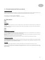
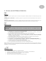
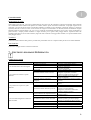
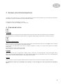
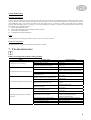
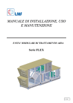
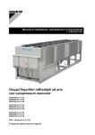
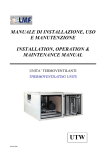
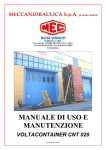
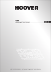
Manuale di installazione,
uso e manutenzione
Installation, operation
& maintenance manual
MANUALE D’INSTALLAZIONE, USO
E MANUTENZIONE
UNITA’ DI RINNOVO ARIA E RECUPERO DI CALORE
TOTALE AD ALTISSIMA EFFICIENZA
SERIE TWR
SIMBOLOGIA
ATTENZIONE
PERICOLO
RISCHIO DI SCOSSE ELETTRICHE
ATTENZIONE SOLO PERSONALE AUTORIZZATO
1 – INTRODUZIONE
pag. 3
2 - DIMENSIONI E PESI
pag. 3
3 – CONFIGURAZIONI DI INSTALLAZIONE
pag. 4
4 – TRASPORTO
pag. 4
5 – INSTALLAZIONE E MESSA IN SERVIZIO
pag. 5
6 – MANUTENZIONE ORDINARIA
pag. 7
7 – GESTIONE ANOMALIE DI IMPIANTO
pag. 8
2
1 - INTRODUZIONE
Gentile Cliente,
le unità di recupero del calore totale ad altissima efficienza sono state progettate e sviluppate per quelle destinazioni d’uso, siano esse
civili, commerciali od industriali, per le quali, in concomitanza al fabbisogno di aria di rinnovo, sia richiesto recupero di calore ed
umidità in modo da ridurre al minimo indispensabile l’impiego di sistemi di post-trattamento dell’aria primaria.
Nella loro essenza, sono funzionalmente costituite (si veda figura 1) da :
1 – ventilatore a girante libera con motore direttamente accoppiato (mandata)
2 – ventilatore a girante libera con motore direttamente accoppiato (espulsione)
3 – recuperatore entalpico di tipo rotativo igroscopico
4 – sezione filtrante (presa aria esterna)
5 – sezione filtrante (ripresa)
6 – sistema di controllo elettrico ed elettronico (opzionale)
Questo manuale riporta le informazioni e quanto ritenuto necessario per il trasporto, l'installazione, l'uso e la manutenzione del
recuperatore di calore, in condizioni di sicurezza e demanda a manuale specifico a corredo per la regolazione elettronica.
La mancata osservanza di quanto descritto in questo manuale od un’inadeguata installazione dell’unità possono arrecare danni diretti
e/o indiretti a persone e/o cose ed essere causa di annullamento della garanzia; in tali circostanze, la Ditta Costruttrice non può
essere ritenuta responsabile.
Verificare, all'atto dell'acquisto, che la macchina sia integra e completa.
Eventuali reclami dovranno essere presentati per iscritto entro 8 giorni dal ricevimento della merce.
Ogni unità è dotata di una targhetta di identificazione che riporta:
-
Indirizzo del Costruttore
Marcatura "CE"
Modello
Numero di matricola
Corrente assorbita massima in "A"
Tensione di alimentazione in "V"
Frequenza di alimentazione "Hz"
Numero di fasi indicato con "Ph"
Data di produzione
Massa in "Kg"
2 – DIMENSIONI E PESI
Dimensioni d’ingombro
La tabella seguente, riferita alla figura 2, riporta le dimensioni caratteristiche della serie.
L
W
H
W1
H1
Φ
mm
mm
mm
mm
mm
kg
400
630
900
1300
2420
1350
1450
1270
400
½”
610
2420
1600
1700
1520
500
½”
930
2870
1900
2000
1820
600
1”
1270
3220
2220
2320
2140
700
1”
1690
3
3 – CONFIGURAZIONI DI INSTALLAZIONE
Orientamenti possibili
Secondo il lay-out delle canalizzazioni dell’aria, è possibile orientare opportunamente le prese aspiranti e prementi dell’unità fino ad
ottenere le seguenti combinazioni, ciascuna delle quali rappresenta una tipologia da specificare in fase d’ordine.
Sono possibili gli orientamenti evidenziati nella figura 3.
(1 = aria di rinnovo, 2 = ripresa ambiente, 3 = immissione, 4 = espulsione)
4 – TRASPORTO
Imballaggio
Ogni unità è caricata su bancale ed avvolta con cellofan protettivo; questo imballo devo rimanere integro fino al momento del
montaggio.
I materiali che non sono stati installati per esigenze tecniche vengono forniti imballati con involucro idoneo fissato all'interno o
esterno dell'unità stessa.
Movimentazione e trasporto
Ogni unità è dotata di adatti punti di sollevamento chiaramente segnalati nello zoccolo. Il sollevamento deve essere eseguito con
un’imbracatura (figura 4), in modo da evitare danni ai pannelli laterali.
Per la movimentazione utilizzare, in funzione del peso, mezzi adeguati come previsto dalla direttiva 89/391/CEE e successive
modifiche.
Il peso di ogni singola macchina è riportato sul seguente manuale.
Negli spostamenti mantenere l’unità così come è stata caricata sul vettore, cercando di evitare rotazioni senza controllo.
Controllo al ricevimento
Al ricevimento dell’unità Vi preghiamo di effettuare un controllo di tutte le parti, al fine di verificare che il trasporto non abbia
causato danneggiamenti; i danni eventualmente presenti devono essere comunicati al vettore, apponendo la clausola di riserva nella
bolla di accompagnamento, specificandone il tipo di danno.
Stoccaggio
In caso di stoccaggio prolungato mantenere le macchine protette dalla polvere e lontano da fonti di vibrazioni e di calore.
La ditta costruttrice declina ogni responsabilità per danneggiamenti dovuti a cattivo scarico o per mancata protezione dagli
agenti atmosferici.
4
5 – INSTALLAZIONE E MESSA IN SERVIZIO
Definizioni
CLIENTE – Il Cliente è la persona, l'ente o la società, che ha acquistato o affittato la macchina e che intende usarla per gli scopi
concepiti.
UTILIZZATORE / OPERATORE – L’utilizzatore o operatore è la persona fisica che è stata autorizzata dal Cliente a operare con
la macchina.
PERSONALE SPECIALIZZATO - Come tali, si intendono quelle persone fisiche che hanno conseguito uno studio specifico e che
sono quindi in grado di riconoscere i pericoli derivati dall'utilizzo di questa macchina e possono essere in grado di evitarli.
Norme di sicurezza
La Ditta Costruttrice declina qualsiasi responsabilità per la mancata osservanza delle norme di sicurezza e di prevenzione
di seguito descritte.
Declina inoltre ogni responsabilità per danni causati da un uso improprio delle unità e/o da modifiche eseguite senza
autorizzazione.
•
•
•
•
•
•
•
•
•
•
L'installazione deve essere effettuata da personale specializzato.
Nelle operazioni di installazione, usare un abbigliamento idoneo ed antinfortunistico, ad esempio: occhiali, guanti,
ecc. come indicato da norma 89/686/CEE e successive.
Durante l’installazione operare in assoluta sicurezza, ambiente pulito e libero da impedimenti.
Rispettare le leggi in vigore nel Paese in cui viene installata la macchina, relativamente all'uso e allo smaltimento
dell'imballo e dei prodotti impiegati per la pulizia e la manutenzione della macchina, nonché osservare quanto
raccomanda il produttore di tali prodotti.
Prima di mettere in funzione l’unità controllare la perfetta integrità dei vari componenti e dell'intero impianto.
Evitare assolutamente di toccare le parti in movimento o di interporsi tra le stesse.
Non procedere con i lavori di manutenzione e di pulizia, se prima non è stata disinserita la linea elettrica.
La manutenzione e la sostituzione delle parti danneggiate o usurate deve essere effettuata solamente da personale
specializzato e seguendo le indicazioni riportate in questo manuale.
Le parti di ricambio devono corrispondere alle esigenze definite dal Costruttore.
In caso di smantellamento delle unità, attenersi alle normative antinquinamento previste.
N.B. L’installatore e l’utilizzatore nell’uso dell’unità devono tenere conto e porre rimedio a tutti gli altri tipi di rischio connessi con
l’impianto. Ad esempio rischi derivanti da ingresso di corpi estranei, oppure rischi dovuti al convogliamento di gas pericolosi
infiammabili o tossici ad alta temperatura.
Operazioni preliminari
•
•
•
•
•
Verificare la perfetta integrità dei vari componenti dell'unità.
Controllare che nell’imballo ci siano contenuti gli accessori per l'installazione, e la documentazione.
Trasportare la sezione imballata il più vicino possibile al luogo di installazione.
Non sovrapporre attrezzi o pesi sull'unità imballata.
Non usare le sezioni di macchina come deposito per attrezzi di cantiere.
5
Scelta del luogo d’installazione e posizionamento della macchina
•
•
•
•
Posizionare l'unità su di una struttura solida adeguata al peso della macchina; interporre sempre opportuni sistemi
smorzanti tra unità e struttura di supporto.
Posizionare l’unità in un luogo in cui lo scarico della condensa possa avvenire facilmente.
Non posizionare l’unità in locali in cui sono presenti gas infiammabili, sostanze acide, aggressive e corrosive che possono
danneggiare i vari componenti in maniera irreparabile.
Prevedere uno spazio laterale libero minimo pari ad una larghezza di macchina nel lato attacchi idraulici e di circa un
metro nel lato opposto, al fine di rendere possibile l’installazione e la manutenzione ordinaria e straordinaria.
Collegamento ai canali
IMPORTANTE : IN CASO DI MANDATA/ESPULSIONE LIBERA (NON CANALIZZATA), PREDISPORRE RETE ANTI
INFORTUNISTICA A NORMA
•
•
•
I canali devono essere dimensionati in funzione dell’impianto e delle caratteristiche aerauliche dell’unità
Per prevenire la formazione di condensa ed attenuare il livello di rumorosità si consiglia di utilizzare canali coibentati.
Per evitare di trasmettere le eventuali vibrazioni della macchina in ambiente, interporre adeguato un giunto antivibrante fra
unità e canali. Tra essi deve comunque essere garantita la continuità elettrica tramite un cavo di terra.
Collegamenti idraulici
Le operazioni di installazione e collegamento delle tubazioni sono operazioni che possono compromettere il buon funzionamento
dell’impianto o peggio, causare danni irreversibili alla macchina. Queste operazioni sono da effettuarsi da personale specializzato.
Collegamento scarico condensa
•
•
•
•
•
Il sistema di evacuazione della condensa deve prevedere, per ogni punto di scarico, un adeguato sifone per consentirne il
deflusso in condizioni di depressione.
Il sifone deve essere eseguito secondo le indicazioni della figura 5
Il sifone deve infine essere dotato di tappo per la pulizia nella parte bassa o deve comunque permettere un veloce
smontaggio per la pulizia.
Il percorso del tubo di scarico condensa deve avere sempre una pendenza verso l’esterno.
Assicurarsi che il tubo per il deflusso della condensa non solleciti l’attacco di scarico dell’unità.
Collegamento batteria ad acqua
•
•
•
•
•
•
•
•
•
•
•
Ogni eventuale batteria alimentata ad acqua è fornita di attacchi “maschio” con filettatura gas.
Le operazioni di serraggio vanno effettuate con cautela per evitare danneggiamenti dei collettori in rame della batteria.
Il percorso dei tubi deve essere studiato in modo da non creare ostacoli in caso di estrazione della batteria dell'unità.
Entrata e uscita acqua devono essere tali da consentire lo scambio termico in controcorrente: seguire quindi le indicazioni
delle targhette ENTRATA ACQUA e USCITA ACQUA.
Prevedere una valvola di sfiato in alto ed una di scarico in basso.
Staffare adeguatamente i tubi all'esterno della unità per evitare di scaricarne il peso sulla batteria.
A collegamento effettuato spingere bene la guarnizione esterna in gomma contro il pannello per evitare trafilamenti d'aria.
La coibentazione deve giungere a filo pannello per evitare pericolo di scottature/condensazione.
Prevedere dispositivo antigelo in caso di funzionamenti in climi particolarmente rigidi.
Prevedere valvole di intercettazione per isolare la batteria dal resto dei circuito in caso di manutenzione straordinaria.
Nel caso di installazione in zone con climi particolarmente freddi, svuotare l’impianto in previsione di lunghi periodi di
ferma dell’impianto.
6
Collegamenti elettrici
Prima di iniziare qualsiasi operazione assicurarsi che la linea di alimentazione generale sia sezionata.
Tutte le linee elettriche devono essere protette a monte a cura dell’installatore.
•
•
I collegamenti elettrici devono essere effettuati da personale specializzato secondo gli schemi forniti; tutte le connessioni
elettriche esterne all’eventuale quadro elettrico dell’unità (opzionale) sono a cura dell’installatore.
Assicurarsi che la tensione e la frequenza riportate sulla targhetta corrispondano a quelle della linea elettrica di
allacciamento.
Eseguire il collegamento dell’unità e di tutti i suoi accessori con cavi di sezione adeguata alla potenza impegnata e
nel rispetto delle normative locali. La loro dimensione deve comunque essere tale da realizzare una caduta di
tensione in fase di avviamento inferiore al 3% di quella nominale.
•
•
•
Per l’alimentazione generale dell'unità e degli accessori non è consentito l’uso di adattatori, prese multiple e/o prolunghe.
E’ dovere dell’installatore prevedere il montaggio il più vicino possibile all’unità di un sezionatore
dell’alimentazione e quanto necessario per la protezione delle parti elettriche.
Collegare l’unità ad una efficace presa di terra, utilizzando l’apposita vite inserita nell’unità stessa.
Per i collegamenti elettrici ad accessori di regolazione (RQU) riferirsi agli schemi specifici allegati alla presente documentazione.
6 – MANUTENZIONE ORDINARIA
PRIMA DI INTRAPRENDERE QUALSIASI OPERAZIONE MANUTENTIVA ACCERTARSI CHE LA MACCHINA
NON SIA E NON POSSA CASUALMENTE O ACCIDENTALMENTE ESSERE ALIMENTATA
ELETTRICAMENTE. E’ QUINDI NECESSARIO TOGLIERE L’ALIMENTAZIONE ELETTRICA AD OGNI
OPERAZIONE DI MANUTENZIONE.
•
•
•
E’ dovere dell’Utilizzatore eseguire sull’unità tutte le operazioni di manutenzione.
Adibire solo personale specializzato alle operazioni di manutenzione.
Se l’unità deve essere smontata, proteggere le mani con dei guanti da lavoro.
Controlli mensili
Filtri aria
E’ possibile accedere alle sezioni filtranti dell’unità tramite i relativi sportelli di ispezione incernierati; seguendo le indicazioni della
figura 6, l’estrazione del filtro avviene mediante rimozione della guida portafiltro laterale 1.
Nel caso di filtro G4 (standard), per la pulizia utilizzare un aspirapolvere o lavare con detergente comune in acqua tiepida, lasciando
asciugare in modo accurato; sostituire il filtro dopo non oltre 3 cicli di pulizia dello stesso. Nel caso di filtro a tasca F7 o F8
(opzionale), sostituire direttamente il filtro quando intasato, imbustarlo opportunamente e portarlo in appositi centri di raccolta, per il
successivo incenerimento. Ricordarsi sempre di rimontare il filtro prima dell’avviamento dell’unità.
Scarico condensa
Garantire la perfetta pulizia della vasca interna e del sistema di scarico. Verificare inoltre l’efficienza dei sifoni.
Batterie ad acqua
Verificare e garantire che le batterie riscaldanti/raffreddanti (opzionali) presentino superfici di scambio termico perfettamente pulite
ed efficienti.
7
Controlli annuali
Recuperatore di calore
Nella maggior parte dei casi, il principio di funzionamento del rotore è tale da permettere la rimozione automatica degli inquinanti
che eventualmente hanno aderito sulla superficie di scambio; laddove questo si dimostri insufficiente, si impieghi un getto di aria
compressa o di acqua ad alta pressione a temperatura ambiente, accedendo al rotore mediante i pannelli di chiusura (o sportelli di
ispezione) adiacenti. Verifcare, inoltre, che la tensione del cingolo di trascinamento sia ottimale (funzione normalmente eseguita
automaticamente da apposita molla); nel caso in cui il sistema di tensionamento automatico non sia più in grado di mantenere la
giusta tensione, è sempre possibile riadattare la cinghia esistente, previo sgancio dalla puleggia motrice, separazione delle due
estremità (unite attraverso un raccordo metallico), taglio del tratto eccedente e rifissaggio delle estremità, con riposizionamento finale
sulla puleggia motrice.
Ventilatori
Verificare la libera rotazione della girante e procedere alla pulizia della stessa se la superficie delle pale dovesse risultare imbrattata.
Parti elettriche
Verificare il serraggio di tutti le connessioni elettriche.
7 – GESTIONE ANOMALIE DI IMPIANTO
Guida ricerca guasti
Anomalia
1) Le sicurezze attive non intervengono
Probabile causa
Sicurezze non collegate
Guasto all’impianto elettrico
Guasto ai componenti elettrici
Filtri sporchi
Resistenza aeraulica esterna eccessiva
2) La portata aria è inferiore a quella
nominale
Serrande di taratura chiuse
Velocità di rotazione ventilatore
inadeguata
Mancanza di componenti interni (filtri?)
3) La portata aria è superiore a quella
nominale
Pannelli ispezione aperti
Resistenza aeraulica inferiore al previsto
Velocità rotazione del recuperatore bassa
Portata aria non sufficiente
4) La resa termica/frigorifera è inferiore a
quella nominale
Alimentazione batterie scarsa od assente
Alimentazione batterie invertita
Pacco batterie intasato o rovinato
Presenza d’aria nel circuito
Temperatura fluido interno non a progetto
Possibile soluzione
Eseguire il collegamento elettrico
Intervento impiantista
Sostituire componente
Intervento assistenza
Pulire o sostituire i filtri
Verificare progetto/impianto
Adeguare, se possibile, velocità di
rotazione ventilatore (tramite inverter)
Aprire le serrande e provvedere alla
taratura di impianto
Elevare la frequenza di rotazione (tramite
inverter)
Montare gli elementi mancanti (ad unità
spenta)
Chiudere le portine
Parzializzare le serrande di taratura
Verificare progetto/impianto
Adeguare la velocità di rotazione del
ventilatore (tramite inverter)
Elevare la frequenza di rotazione del rotore
(tramite inverter)
Vedi anomalia 2)
Aprire le valvole di intercettazione
Verificare portata e prevalenza pompe
Verificare collegamento elettrico pompe
Invertire entrata/uscita
Pulire le batterie o pettinarle
Sfiatare le batterie
Regolare i termostati sui generatori
8
INSTALLATION, OPERATION &
MAINTENANCE MANUAL
HIGH EFFICIENCY AIR-TO-AIR THERMAL WHEEL
HEAT & MOISTURE RECOVERY UNIT
SERIES TWR
SYMBOLOGY
ATTENTION
DANGER
HIGH RISK OF ELECTRIC SHOCK
ATTENTION: AUTHORIZED PERSONNEL ONLY
1 – INTRODUCTION
page 3
2 - DIMENSIONS & WEIGHTS
page 3
3 – INSTALLATION CONFIGURATIONS
page 4
4 – TRANSPORTATION
page 4
5 – INSTALLATION & CONNECTION
page 5
6 – STANDARD MAINTENANCE
page 7
7 – TROUBLESHOOTING
page 8
2
1 - INTRODUCTION
Dear Customer,
the thermal wheel heat & moisture recovery units are designed and developed for civil, commercial or industrial buildings requiring the
air renewal and very high heat & moisture recovery efficiency at the same time so that any integration system must be undersized.
In their basic working principle, they consist in (see figure 1) :
1 – supply plug fan
2 – exhaust plug fan
3 – enthalpic thermal wheel
4 – outside air filter
5 - return air filter
6 – electrical board and control device (option)
This instruction manual supplies the necessary information for the transportation, the installation, operation and maintenance of the unit,
under safety working conditions. For information about control mode, read the specific additional manual.
Lack of observation of the details found within this manual, and an inadequate installation of the unit may cause the withdrawal of the
warranty supplied with the equipment.
Furthermore, the Supplier will not respond to any eventual damage, whether direct or indirect, caused by the incorrect installation, or for
damages caused by the installation being effectuated by inexperienced or unauthorised personnel.
Verify, upon acquisition, that the apparatus is complete and supplied as described.
Any eventual disputes must be presented in writing within 8 days from the reception of the goods.
Each unit is provided with identification plate listing the following:
-
Address of Constructor
“CE” Mark
Model
Serial Number
Maximum current in “A”
Power supply voltage in “V”
Power supply frequency in “Hz”
Number of phases indicated with “Ph”
Date of fabrication
Gross weight in “kg”
2 – DIMENSIONS & WEIGHTS
Packing dimensions
The following table, referred to the figure 2, shows the characteristic dimensions of the series.
L
W
H
W1
H1
Φ
mm
mm
mm
mm
mm
kg
400
630
900
1300
2420
1350
1450
1270
400
½”
610
2420
1600
1700
1520
500
½”
930
2870
1900
2000
1820
600
1”
1270
3220
2220
2320
2140
700
1”
1690
3
3 – INSTALLATION CONFIGURATIONS
According to the air duct lay-out, it is possible to rotate adequately the unit air inlets and outlets to give the following combinations,
each of them is a specific unit orientation to be specified when ordering.
Configurations shown on the figure 3 are possible.
(1 = fresh air, 2 = return air, 3 = supply air, 4 = exhaust air)
4 – TRANSPORTATION
Packaging
Each unit is put on bench and protected with cellophane film; the protection must remain intact until the moment of installation.
The materials that are not mounted for technical motives are supplied in fitted packing fixed externally or internally to the unit.
Moving & transportation
Each unit is provided with lifting holes clearly shown on the baseframe. The lifting must be done as shown on figure 4 with an adequate
harness, as well as to avoid any damage on unit panels and frame.
For the lifting and transportation of the unit, use adequate equipment, according to the 89/391/CEE regulations and further
modifications.
Each individual unit weight is listed in this manual.
While moving,try to avoid rotation without control.
Checklist
Upon reception of the unit, we suggest that a complete control is carried out, to verify that the unit is intact and complete, and no
damage has been sustained during transport. Any eventual damage revealed must be communicated to the carrier, demonstrating the
reserve clause within the transport documents, specifying the type of damage.
Storing
In case of long term storage, the apparatus must be kept free from dust, and away from areas susceptible to heat and vibration.
The Manufacturer declines any responsibility for any damage as a result of negligence or lack of protection from atmospheric
agents.
4
5 – INSTALLATION & CONNECTION
Definitions
CUSTOMER – The Customer is the person, activity or the society, that has bought or hired the unit, and intends to utilise the
machinery for its intended use.
USER / OPERATOR – The User or Operator is the actual person that has been authorised by the Customer to utilise the unit.
QUALIFIED PERSONNEL - Defined as the person who has followed a relevant specific course of study, and so is able to understand
the dangers derived from the use of the machinery, and in turn, due to this, are capable of solving major dilemmas.
Safety regulations
The Manufacturer declines any responsibility for failure to respect the Safety Regulations and the prevention as described
below.
Furthermore, the Manufacturer declines any responsibility for damage caused by the improper use of the unit and/or
modifications carried out without proper authorisation.
•
•
•
•
•
•
•
•
•
•
Qualified personnel must carry out the installation.
During the installation operation, use protective clothing, for example: glasses, gloves, etc. as indicated by 89/686/CEE and
successive regulations.
During the installation operate in absolute security, pollution free air and in an area free of obstructions.
Respect the regulations in force in the country in which the apparatus is being installed. Specifically relative to its use, and to
the disposal of packing and products used for the cleaning and maintenance of the unit. Respect the recommendations given
by the producers of such products.
Before placing in function the unit, check the perfect connection of the various components and the internal parts of the
system.
Avoid at all costs human contact with moving parts and contact with the parts themselves.
Do not commence with servicing or cleaning of the unit, before the unit has been disconnected from the main supply.
The maintenance and the substitution of damaged or consumed parts must be carried out only by specialised personnel,
following the indications found within this manual.
Spare parts must correspond to the requirements specified by Manufacturer.
In case of dismantling of the unit, respect the anti-pollution regulations in force.
N.B. The installer and the user of the apparatus must take into account, and solve problems, connected with any other type of risk that
may occur to the unit. For example, risks derived from the entrance of foreign bodies, or risks due to the presence of flammable or toxic
gas.
Preliminary operations
•
•
•
•
•
Check the perfect condition of all unit components.
Check that packaging is complete with documentation and all needed for installation.
Move the unit to as close as possible site of installation.
Do not place tools or weights on top of the packed unit.
Do not use any unit accessible section as yard tool store.
5
Characteristics of the place of installation and machine positioning
•
•
•
•
Place the unit on a solid structure, suitable for the unit weight; always interpose adequate antivibrating systems between the
unit and support frame.
Position the unit in a point where the condensation discharge may occur easily.
Do not position the unit in an area in which flammable gases, acidic or corrosive substances are present. They may damage
various components in an irreparable manner.
A minimum side technical space of one unit width must be provided on water connection side and 1 m on the opposite
side, in order to make installation and maintenance operations possible.
Connection to air ducts
IMPORTANT : IN CASE OF FREE FAN OUTLET (BOTH SUPPLY AND EXHAUST), INSTALL A SAFETY GRID
ACCORDING TO DOMESTIC SAFETY RULES
•
•
•
Air ducts must be sized in order to match unit & plant air performances
A thermal and sound insulation on the ducts is suggested in order to prevent water condensation and reduce plant noise level.
Interpose a flexible connection between unit and each air duct, so that unit mechanical vibrations to the room are strongly
reduced. Anycase, electrical continuity between unit and ducts mus be ensured by a ground cable.
Water connections
The installation and connecting of the piping is an operation that must be done correctly, otherwise it may compromise the performance
of the system. At worst it may cause irreversible damage to the machine. These operations are to be effectuated by qualified personnel.
Condensation outlet connection
•
•
•
•
•
The system of drainage must provide an adequate trap, on each discharge point, able to allow the condensation running off on
underpressure conditions.
The trap must be sized as shown on the figure 5
The trap must have a tap for correct cleaning of the lower part, and must allow an easy disassembly.
The path of the condensation drainage tube must always have a gradient toward external.
Insure that the condensation run-off tube does not interfere with discharge of the unit.
Water coil connection
•
•
•
•
•
•
•
•
•
•
•
•
The changeover water coil is supplied with GAS “male” threaded headers.
The tightening must be carried out with extreme care to avoid damage to the copper collectors of the coil.
The path of the tubes must be studied in a way to avoid obstacles should it be necessary to extract the unit coil.
Inlet and outlet water must consent the thermal exchange against the current. Follow instructions found on the WATER
INLET and WATER OUTLET plate.
Provide an air valve at the top of the unit, and a water discharge valve at the bottom.
Reinforce sufficiently the units external tubes to avoid offloading the weight onto the coil.
Once connection has been effectuated, fix the external seal flush against the control panel, in this way avoiding the passing of
air.
The insulation must not rest against the panelling, as this may provoke burning.
For control purposes, organize the interception of the tube side coil when the fan is off, to avoid internal overheating and
possible damage to internal components.
Provide an anti-freeze system.
Provide a cut out switch to isolate the coil from the rest of the circuit in case of extensive maintenance needs.
Should the unit be installed in particularly cold areas, drain completely before plant shut-off long periods.
6
Electrical connections
Before starting any operation, insure that the general power supply has been isolated.
All the electrical connections must be protected at the source by the installer.
•
•
Qualified personnel according to the supplied schemes must carry out the electrical connections at the control panel (option).
Insure that the voltage and the frequency shown on the technical plate correspond to the connecting power supply.
Follow the connection of the unit and its accessories using adequate cabling for the power used, and respecting the
country regulations. The dimensions of the cabling must be sufficient to support a voltage drop in start up phase
inferior to 3% of the nominal.
•
•
•
For the general power supply of the unit, and its accessories, the use of adapters, multiple plugs and extension leads is to be
avoided.
It is the responsibility of the installer to insure that the installation of the unit is as close as possible to the mains power
supply, or sufficiently close to protect the electrical parts.
Connect the unit to an efficient ground point.
For connection to control equipment (RQU option) see specific wiring diagrams attached to this document.
6 – STANDARD MAINTENANCE
BEFORE FOLLOWING ANY TYPE OF MAINTENANCE OPERATION, BE CERTAIN THAT THE UNIT MAY
NOT CASUALLY OR ACCIDENTALLY BE CONNECTED TO THE ELECTRICAL MAINS SUPPLY. THERFORE
IT IS NECESSARY TO SHUTDOWN THE UNIT’S POWER SUPPLY PRIOR TO MAINTENANCE.
•
•
•
It is the responsibility of the User to carry out all types of maintenance operations.
Only personnel previously trained and qualified may carry out maintenance operations.
Should the unit require disassembly, hand protection is required.
Monthly maintenance
Air filters
Filter section can be entered through filter access door; following the figure 6, filter removal is done by dismounting the side filter
frame 1.
In case of G4 (standard) filter, for the cleaning use a vacuum cleaner or wash with normal detergent and warm water, allowing to dry
well. Replace a new filter after max 3 cleaning cycles. In case of F7 or F8 bag filter (optional), it is to be replaced when dirty, packaged
and brought to incinerate at a waste collection center. Remember to install the clean filter before switching on the unit again.
Condensation discharge
Each drain tray and discharge system (water traps included) are to be kept clean and efficient.
Water coil
Check that the coil exchanger (optional ) is as clean as efficient to guarantee the design performance..
7
Yearly maintenance
Thermal wheel device
In most cases, the counterflow principle will allow the rotary wheel to self-clean of contaminants that may adhere to the surface of the
rotor. In situation where self-cleaning is not sufficient, the rotary wheel can be cleaned with compressed air or high pressure water (at
room temperature only); rotor will be accessible by the door panels close to it. Moreover, check the right belt tension (operation
generally and automatically done by a spring); in case of the automatic belt adjuster is not able to keep the right tension anymore, the
existing belt can be adjusted as follows :
1) remove the belt from the pulley
2) remove the belt linkage with a small Philips head screwdriver
3) cut the belt to the required belt
4) re-attach the belt linkage and tighten.
Fans
Check the impeller is running free from any friction; clean it if its surface is dirtied.
Electrical components
Check the tightness of all electrical connections and restore if needed.
7 – TROUBLESHOOTING
Failure searching and problem solving schedule
Failure
1) Safety devices not working
Probable cause
Safety devices not wired
Electrical plant on failure
Electrical component(s) on failure
Air filters dirty
External static pressure too high
2) Current airflow lower than design one
Adjusting dampers closed
Fan speed too low
Internal component(s) missing (filters ?)
Access doors open
3) Current airflow higher than design one
External static pressure too low
Fan speed too high
Rotory wheel speed too low
Airflow too low
4) Heating/cooling capacity lower than
design one
Water flow too low or absent
Not counterflow coil working mode
Coil front surface dirtied or damaged
Air inside the water circuit
Media temperature not right
Possible solution
Restore the wiring
Call service
Replace the component(s)
Call service
Clean or replace filters
Check project/air plant
Adjust, if possible, fan speed (by inverter)
Open the dampers and balance the air plant
Increase motor working frequency
(by inverter)
Install the missing component(s) (unit
switched off)
Close the access doors
Balance the air plant by the adjusting
dampers
Check project/air plant
Reduce motor working frequency
(by inverter)
Increase rotor working frequency
(by inverter)
See failure 2)
Close water valves
Check water pump performance
Check water pump wiring
Exchange water inlet/outlet connection
Clean the coil fins or comb them
Open the vent valves
Adjust thermostat on chiller/boiler
8
Fig. 1
Fig. 2
Fig. 3
Fig. 4
Fig. 5
Fig. 6