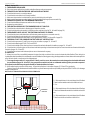
1
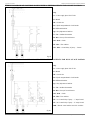
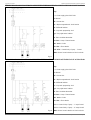
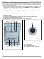
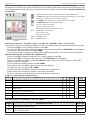
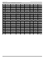
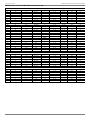
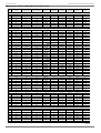
Manuale
d'installazione
uso
manutenzione
Instruction and
Installation
handbook
fore sealed
radiant
tube heater
dei pannelli radianti Panrad
N° P01_2001
updated to 01/01/2001
aggiornato al 01/01/2001
LIBRETTO ISTRUZIONI PANNELLI RADIANTI PANRAD
INDEX
GENERAL REMARKS
- General remarks ........................................................................................................................................................page
USE
- Use.............................................................................................................................................................................. page
RECOMMENDATIONS FOR INSTALLATION
- Recommendations for installation ...............................................................................................................................page
CHARACTERISTICS OF PANRAD RADIANT TUBES
- Technical information concerning PANRAD ............................................................................................................... page
ELEMENTS OF PANRAD RADIANT TUBES
- Elements of PANRAD Radiant Tubes ........................................................................................................................page
EXTERNAL DIMENSIONS OF PANRAD RADIANT TUBES
- External dimensions of PANRAD Radiant Tubes........................................................................................................page
EXTERNAL DIMENSIONS OF BURNERS
- External dimensions of burners ................................................................................................................................. page
BURNER: INTERIOR VIEW
- Burner: interior view........................................................................................ ............................................................. page
ASSEMBLY OUTLINES
- Assembly of Radiant Tube in 3 or 6 mt lengths ...........................................................................................................page
ASSEMBLY
- Assembly of heat exchanger pipes .............................................................................................................................page
- Assembly of brackets .................................................................................................................................................page
- Assembly of reflectors ................................................................................................................................................page
- Assembly of reflector end closure ...............................................................................................................................page
INSTALLATION
- Installation of insulation ...............................................................................................................................................page
- Ceiling Installation............................................................................................................................................................page
- Wall Installation.. ........................................................................................................................................................ page
INSTALLATION OF INTAKE AND EXHAUST CHIMNEY
- Installation of chimney type B22 and C32 through roof ................................................................................................... page
- Installation of chimney type B22 e C32 through wall ...................................................................................................... page
- Installation of concentric chimney type C32 ...................................................................................................................................................................................................... page
GAS SUPPLY
- Gas supply .................................................................................................................................................................page
POWER SUPPLY
- Electrical Characteristics of Radiant Tubes ..................................................................................................................page
- Electrical connections to the control panel ...................................................................................................................page
- Examples of wiring diagrams .....................................................................................................................................page
TEMPERATURE CONTROL AND ADJUSTMENTS
- Description and elements of control panels .................................................................................................................page
- Installation and use of thermosthat for On/Off PANRAD ...............................................................................................page
- Installation and use of thermosthat for Dual Stage PANRAD ....................................................................................... page
- Installation and use of programmer clock ....................................................................................................................page
POSITION OF THE ELECTRODES
- Position of the electrodes ............................................................................................................................................page
START-UP
- Start-up ...................................................................................................................................................................... page
- Solenoid valve adjustments and gas pressure checking .............................................................................................. page
TROUBLESHOOTING
- What to do if ............................................................................................................................................................... page
- Warnings.................................................................................................................................................................... page
- Distance from flammable materials ............................................................................................................................ page
PRESSURE AND NOZZLES
- Table pressure and nozzles ....................................................................................................................................... page
FRACCARO
Officine Termotecniche via Sile, 32 Castelfranco Veneto (TV) Tel. 0423/721003 - Fax 0423/493223 - www.fraccaro.it - e mail: [email protected]
3
3
3
4
5
6
6
7
8-9
10 - 12
13 - 14
15
16
16 - 17
18
18
19 - 20
20 - 21
21
22
22
22
23 - 24
25
26 - 27
28 - 29
30 - 31
32
33
33
34
34
34
35- 37
Pag. 2
aggiornato al 01/01/2001
LIBRETTO ISTRUZIONI PANNELLI RADIANTI PANRAD
GENERAL REMARKS
This instruction manual should always be kept with the PANRAD Radiant Tube, so that it can be consulted by the maintenance personnel or
by the user in case of need.
The installation of PANRAD Radiant Tube should be performed in respect of the regulations in effect in each country, according to the
manufacturer's instructions or those of professionally qualified personnel with specific technical expertise in the field of radiation heating.
Improper installation and improper use of the system could cause damage to persons, animals or objects for which the manufacturer is not
responsible.
Before performing any operation of cleaning or maintenance, disconnect the burner from the supply mains using the switch on the electric control
panel and/or the organs of interception provided; in case of breakdown and/or malfunction of the burner it should be disconnected immediately.
No attempt at repair or other intervention should be attempted and the user should contact our local Technical Service Center.
If the system should be taken out of use for a prolonged period, close the gas taps and disconnect power using the circuit breaker on the burner.
To ensure the efficiency of the appliance and proper operation it is a good rule to have the annual maintenance performed by personnel from
our Technical Service Center according to the manufacturer's instructions.
Use of the equipment is restricted to authorized personnel only.
Start-up of the unit, and its transformation from gas of one type to gas of another, should be done exclusively by personnel from
the Technical Service Center authorized by Fraccaro srl.
USE
Unskilled persons should not be allowed to use any device powered by electricity and the following precautions should be observed:
- do not touch the device with damp or wet parts of the body;
- protect the burner adequately against atmospheric agents if installed outdoors;
- provide efficient grounding according to the local safety regulations;
- do not use the gas pipes to ground electrical devices;
- do not touch hot parts of the equipment such as the exchanger pipes, the combusted gas exhaust pipe, as during and after operation (for
a certain amount of time) they are very hot;
- do not spray water or other liquids on the burner;
- do not place any object on the burner or radiating pipes.
If you smell gas, act as follows:
- do not turn on any switches or do anything that could cause sparks;
- open doors and windows immediately to create a draft and air the room, then close the gas taps;
- request the intervention of professionally qualified personnel.
RECOMMENDATIONS FOR INSTALLATIONS
This device must be installed in conformity with local regulations in effect and used only in a well-ventilated place.
Consult the instruction manual before installing and using the equipment.
FRACCARO SRL COULD NOT BE HELD RESPONSIBLE
IF MAIN RULES WRITTEN IN THIS MANUAL WERE NOT
OBSERVED
DURING
INSTALLATION.
A
WRONG
INSTALLATION COULD CAUSE BAD WORKING OF THE
APPLIANCES OR MAKE THE PLANT NOT WORKING AT ALL.
FRACCARO
Officine Termotecniche via Sile, 32 Castelfranco Veneto (TV) Tel. 0423/721003 - Fax 0423/493223 - www.fraccaro.it - e mail: [email protected]
Pag. 3
LIBRETTO ISTRUZIONI PANNELLI RADIANTI PANRAD
aggiornato al 01/01/2001
BURNER CHARACTERISTICS
On/Off working Models
Modelli con funzionamento On/Off
FRA2
FRA3
FRA4.1
FRA4
FRB3
FRB4
FRB4.1
FRC4
FRC5
20,00
30,00
35,00
40,00
30,00
40,00
45,00
40,00
50,00
G20 [m³st/h]
1,90
2,85
3,33
3,81
3,81
3,81
4,28
3,81
4,76
G25 [m³st/h]
2,21
3,24
3,87
4,43
4,43
4,43
4,98
4,43
5,54
G30
[Kg/h]
1,45
2,18
2,54
2,91
2,91
2,91
3,27
2,91
3,63
Dual-Stage working ModelsG31
[Kg/h]
1,42
2,14
2,50
2,85
2,85
2,85
3,21
2,85
3,57
Potenza
Consumo
PCS
Power
Max.
Consumption
[kW]
Modelli con funzionamento a 2 stadi
Potenza
Consumo
PCS
Power
Min/Max
Consumption
Tipo di bruciatore
Diametro attacco gas
FRA2S2
[kW]
10/20
FRA3S2 FRA4.1S2 FRA4S2
20/30
30/35
30/40
30/40
30/45
40/50
2,85÷3,81 2,85÷4,28
3,81÷4,76
G25 [m³st/h] 1,10÷2,21 2,21÷3,24 3,24÷3,87 3,32÷4,43
3,32÷4,43 3,32÷4,98
4,43÷5,54
G30
[Kg/h]
0,72÷1,45 1,45÷2,18 2,18÷2,54 2,18÷2,91
2,18÷2,91 2,18÷3,27
2,91÷3,63
G31
[Kg/h]
0,71÷1,42 1,42÷2,14 2,14÷2,50 2,14÷2,85
2,14÷2,85 2,14÷3,21
2,85÷3,57
Atmosph.
Atmosferico
Gas connector diameter
1/2"
[VAC
1N]
Alimentazione elettrica
Power supply
Assorbimento elettrico
Assorbimento elettrico
[Watt]
Power absorbed
Power absorbed[A]
Peso del bruciatore
Burner weight
1~ \ N \ 50 Hz 230V
56,00
0,50
[Kg]
17,00
[Kg] of unit
Total weight
108,00
N° venturi frazionati in vena d'aria a
2,00
3,00
depressione
Number of Venturi [n°]
tubes fractioned
in
Lunghezza dei tubi scambiatori
147,00
[mt] of exchangers6,00
Length
pipes
4,00
9,00
[mm]
Diametro attacco condotto scarico fumi
[mm]
Diam. of exchangers pipes
Diam. of fume exhaust pipe 80,00
Diametro attacco condotto aspirazione aria
[mm]
Diam. of air intake pipe
Aria necessaria per la corretta combustione [m³/h]
185,00
4,00
3,00
depression
air vein
Diametro dei tubi scambiatori
Categoria gas
FRC5S2
G20 [m³st/h] 0,95÷1,90 1,90÷2,85 2,85÷3,33 2,85÷3,81
Type of burner
Peso apparecchio completo
FRB4S2 FRB4.1S2
12,00
89,00
40,00
60,00
75,00
80,00
80,00
60,00
80,00
90,00
80,00
II2H3+
Air required for proper combustion
Gas category
FRACCARO
100,00
Officine Termotecniche via Sile, 32 Castelfranco Veneto (TV) Tel. 0423/721003 - Fax 0423/493223 - www.fraccaro.it - e mail: [email protected]
Tab. 1
Pag. 4
LIBRETTO ISTRUZIONI PANNELLI RADIANTI PANRAD
aggiornato al 01/01/2001
ELEMENTS OF RADIANT TUBES
3
4
5
2
6
1
7
8
9
17
8
16
15
14
10
11
13
12
Key:
1 =
2 =
3 =
4 =
5 =
6 =
7 =
8 =
9 =
10 =
11 =
12 =
13 =
14 =
15 =
16 =
17 =
Fig. 1
Dish securing screws
Reflecting dish in aluminium
End closure securing screws
End closure
Flange
Head union
Expander
Carrying bracket (fig.21 page 13)
Exchanger pipe
Dish support bracket (fig. 26 page 14)
Electrical plug (fig. 4 page 7)
Lever operated closure, opened by screwdriver
Electrical socket (fig. 4 page 7)
Cover with locks
1/2" gas union
Combustion air intake
Burned gases exhaustion port
FRACCARO
Officine Termotecniche via Sile, 32 Castelfranco Veneto (TV) Tel. 0423/721003 - Fax 0423/493223 - www.fraccaro.it - e mail: [email protected]
Pag. 5
LIBRETTO ISTRUZIONI PANNELLI RADIANTI PANRAD
aggiornato al 01/01/2001
EXTERNAL DIMENSIONS OF RADIANT TUBES
Fig. 2
B
A
70
0
FRA2
FRA2S2
FRA3
FRA3S2
A [mm]
FRA4
FRA4S2
FRA4.1
FRA4.1S2
FRB4
FRB4S2
FRB3
6.060
B [mm]
FRB4.1
FRB4.1S2
FRC5
FRC5S2
FRC4
8.970
11.900
9.360
12.290
390
A+B [mm]
6.450
Tab. 2
EXTERNAL DIMENSIONS OF BURNERS
390
460
260
96
260
230
115
54 42
36
134
ø76
00
ø1
00
ø1
460
100
390
ø 1/2"
ø8
see fig. 4 of page 7
100
96
182
0
100
ø80
Fig. 3
C
C [mm]
C [mm]
FRA2
FRA3
FRA4
FRA4.1
FRB3
FRB4
FRB4.1
FRC4
FRC5
160
160
160
160
160
185
185
185
185
FRA2S2
FRA3S2
FRA4S2
FRA4.1S2
FRB4S2
FRB4.1S2
FRC5S2
160
160
160
160
185
185
185
Tab. 3
FRACCARO
Officine Termotecniche via Sile, 32 Castelfranco Veneto (TV) Tel. 0423/721003 - Fax 0423/493223 - www.fraccaro.it - e mail: [email protected]
Pag. 6
LIBRETTO ISTRUZIONI PANNELLI RADIANTI PANRAD
aggiornato al 01/01/2001
BURNER: INTERIOR VIEW*
On/Off Burners
1
2
3
14
13
4
5
6
9
8
7
Dual-stage Burners
17 16 15 18
17 16 15
12
11
10
Fig. 4
KEY:
1
2
3
4
5
6
7
8
9
=
=
=
=
=
=
=
=
=
Scroll
Electrode unit
Venturi tubes
Control box
Nozzle
Nozzle bearing block
"Burner shut-down" indicator light (red)
Suction tube fitting port
Solenoid valve
10
11
12
13
14
15
16
17
18
=
=
=
=
=
=
=
=
=
Gas pressure switch
Gas supply union
Air vacuum switch
"Burner operating" indicator light (green)
Fan
Plug (with fuse 2A inside, only for On/Off burners)
Burned gas exhaustion hole
Socket
Fuse 2A (only for Dual-Stage burners)
* For a clearer view of burner components, the above diagram shows an overturned burner.
FRACCARO
Officine Termotecniche via Sile, 32 Castelfranco Veneto (TV) Tel. 0423/721003 - Fax 0423/493223 - www.fraccaro.it - e mail: [email protected]
Pag. 7
LIBRETTO ISTRUZIONI PANNELLI RADIANTI PANRAD
aggiornato al 01/01/2001
PANRAD ASSEMBLY OUTLINES
In fig. 5-6-7 you can find assembly outlines of radiant tubes with flanged pipes in 3 or 6 mt. lengths Place the dish support bracket type A
and carrying bracket type B as follows.
5840
A
A
B
Bruc.
In 6 mt. lengths
Asp.
5707
2920
Burner
Models:
FRA2, FRA3 and FRA4.1
FRA2S2,
FRA3S2
and
FRA4.1S2
2920
A
B
B
Bruc.
In 3 mt. lengths
Asp.
Fan
2787
Fig. 5
2920
5840
A
B
A
B
In 6 mt. lengths
2787
2920
Burner
2920
A
B
Models:
FRB3, FRB4
FRB4S2
2920
B
and
B
Bruc.
In 3 mt. lengths
Asp.
2787
Fan
Fig. 6
5840
A
5840
A
B
A
B
Bruc.
In 6 mt. lengths
Asp.
5707
2920
A
2920
B
2920
B
Model:
FRC4
2920
B
B
Bruc.
In 3 mt. lengths
Asp.
2787
FRACCARO
Officine Termotecniche via Sile, 32 Castelfranco Veneto (TV) Tel. 0423/721003 - Fax 0423/493223 - www.fraccaro.it - e mail: [email protected]
Fig. 7
Pag. 8
LIBRETTO ISTRUZIONI PANNELLI RADIANTI PANRAD
aggiornato al 01/01/2001
PANRAD ASSEMBLY OUTLINES
In fig. 8-9-10 you can find assembly outlines of radiant tubes with flanged pipes in 3 or 6 mt. lengths. Place the dish support bracket type
A and carrying bracket type B as follows.
2920
2920 special steel
A
B
B
Bruc.
In 3 mt. lengths
Asp.
2787
Models:
FRA4 and FRA4S2
2920
2920 special steel
A
B
B
Bruc.
In 3 and 6 mt. lengths
Asp.
5707
A
2920 special
steel
Fig. 8
2920
B
2920
B
B
Bruc.
In 3 mt. lengths
Asp.
2787
Models:
FRB4.1 and FRB4.1S2
2920
special steel
A
5840
B
A
B
Bruc.
In 6 mt. lengths
Asp.
Fig. 9
5707
2920 special
steel
2920 special
steel
A
B
2920
B
2920
B
B
Bruc.
In 3 mt. lengths
Asp.
2787
Models:
FRC5 and FRC5S2
5840 special steel
A
A
5840
B
A
B
Bruc.
In 6 mt. lengths
Asp.
5707
FRACCARO
Officine Termotecniche via Sile, 32 Castelfranco Veneto (TV) Tel. 0423/721003 - Fax 0423/493223 - www.fraccaro.it - e mail: [email protected]
Fig. 10
Pag. 9
LIBRETTO ISTRUZIONI PANNELLI RADIANTI PANRAD
aggiornato al 01/01/2001
ASSEMBLY OF HEAT EXCHANGER PIPES
Radiant Tube is composed of:
1) A combustion/exhaustion group assembled inside a protective box;
2) Flanged pipes in different lengths;
3) A flanged head union;
4) A flanged expander;
5) A set of brackets type A and type B;
6) Reflecting dish in different pieces;
7) A set of ceramic fibre gaskets with M8 nuts and securing screws.
After the above mentioned material has been noticed, start assembly operation as follows:
a) Place the flanged exchanger pipes on the floor or on a flat surface, following outlines of page 8 and page 9 according to the model.
b) Place the pipe having the 5-holes flange of fig. 11 detail A on burner connection of cover fig. 12, so that the 5° hole of the flange is inserted
on the steel screw welded on the cover as shown in fig. 13 (burner side). In order to ease the identification, the 5-holes flange is painted
red.
Details of the flanged tube for
connecting burner
A Details of
5-holes flange
B
B Details of the
side for connecting tube
A
5°hole for connecting the steel screw
Fig. 11
rn
bu
ven
tila
er
ventilator side
tor
steel
screw
burner side
steel
screw
Fig. 12
Fig. 13
FRACCARO
Officine Termotecniche via Sile, 32 Castelfranco Veneto (TV) Tel. 0423/721003 - Fax 0423/493223 - www.fraccaro.it - e mail: [email protected]
Pag. 10
LIBRETTO ISTRUZIONI PANNELLI RADIANTI PANRAD
aggiornato al 01/01/2001
c) Place the flanged short pipe fig. 14 (2787 or 5707 mm. length) on the side of the expander as shown on fig. 15-16.
To ease identification of this short pipe, the flange is white painted.
Key:
1 = Flanged head union
2 = M8 nut
3 = Washer
4 = Ceramic fibre gasket
5 = Flanged expander
6 = M8 screw
7 = Short flanged pipe
8 = Standard flanged pipe
1
2
3
6
7
278
7/
7
570
3
4
7
5
Fig. 14
Fig. 15
THE EXPANSION BEND MUST BE POSITIONED
ON THE RETURN SIDE
8
bu
r
rne
sid
e
7
ve
nti
la
sid
tor
e
Key:
7 = Short flanged pipe 2787/5707 mm
8 = Standard length flanged pipe 2920/5840
mm
Fig. 16
d) Insert one gasket on every connection between pipes of the circuit (fig. 17), tighten through bolts and washers (fig. 18).
6
3
4
3
2
Fig. 17
FRACCARO
Officine Termotecniche via Sile, 32 Castelfranco Veneto (TV) Tel. 0423/721003 - Fax 0423/493223 - www.fraccaro.it - e mail: [email protected]
Fig. 18
Pag. 11
LIBRETTO ISTRUZIONI PANNELLI RADIANTI PANRAD
aggiornato al 01/01/2001
e) Upon completion, be sure that radiant tube is as shown on fig. 19, otherwise repeat and check all operations as previously described.
Intake air
Exhaust fumes
1
Gas connection
2
4
3
4
5
6
7
Flange connecting
ventilator
Flange connecting
burner provided with
hole for steel screw
Key:
1 = Cover burner/aspirator
2 = Flanged Tube, burner side
3 = Ceramic fibre gasket
4 = Standard flanged pipe
5 = Short flanged pipe
6 = Flanged expansion bend
7 = Head union
Fig. 19
WRONG INSTALLATION
On fig. 20 a WRONG installation is shown, the expansion bend must NOT be positioned on delivery pipe or burner side.
WRONG POSITION
Burner Bruc.
Asp.
Fan
Fig. 20
FRACCARO
Officine Termotecniche via Sile, 32 Castelfranco Veneto (TV) Tel. 0423/721003 - Fax 0423/493223 - www.fraccaro.it - e mail: [email protected]
Pag. 12
LIBRETTO ISTRUZIONI PANNELLI RADIANTI PANRAD
aggiornato al 01/01/2001
ASSEMBLY OF CARRYING BRACKET type B
- Place the carrying bracket type B fig. 21 as shown in fig. 5 - 6 - 7 - 8 - 9 - 10 of pages 8-9.
- Rest the brackets type B on the lower part of the pipes as shown in fig. 22 - 23.
- Open the tabs on the small bracket slightly as shown in fig. 24 and insert the carrying bracket in the small bracket fig. 25, repeating this
operation for the other exchanger and all the carrying brackets to be mounted.
- Upon completion, close the tabs on the small bracket again, taking care not to break and/or crack the tab.
Carrying bracket type B
Fig. 21
Fig. 22
Open the tabs on the small bracket
Fig. 23
TAKE CARE NOT TO BREAK AND/OR CRACK THE
TABS ON THE SMALL BRACKET.
Fig. 24
UPON COMPLETION OF
ASSEMBLY OPERATIONS, TAKE CARE
TO CLOSE THE TABS ON THE SMALL
BRACKET.
Fig. 25
FRACCARO
Officine Termotecniche via Sile, 32 Castelfranco Veneto (TV) Tel. 0423/721003 - Fax 0423/493223 - www.fraccaro.it - e mail: [email protected]
Pag. 13
LIBRETTO ISTRUZIONI PANNELLI RADIANTI PANRAD
aggiornato al 01/01/2001
ASSEMBLY OF DISH SUPPORT BRACKET type A
- Place the dish support brackets type A fig. 26 as shown in fig. 5 - 6 - 7 - 8 - 9 - 10 of pages 8-9.
- Rest the brackets type A on the lower part of the pipes as shown in fig. 27 - 28.
- Open the tabs on the small bracket as shown in fig. 29, then insert the carrying bracket in the small bracket fig. 30 repeating this operation
for the other exchanger and all the dish support brackets type A to be mounted.
- Upon completion, close the tabs on the small bracket again, taking care not to break and/or crack the tab.
Dish support bracket type A
Fig. 26
Fig. 27
Open the tabs on the small bracket
Fig. 28
TAKE CARE NOT TO BREAK AND/OR CRACK THE
TABS.
Fig. 29
UPON COMPLETION OF
ASSEMBLY OPERATION, TAKE CARE
TO CLOSE THE TABS ON THE SMALL
BRACKET.
Fig. 30
FRACCARO
Officine Termotecniche via Sile, 32 Castelfranco Veneto (TV) Tel. 0423/721003 - Fax 0423/493223 - www.fraccaro.it - e mail: [email protected]
Pag. 14
LIBRETTO ISTRUZIONI PANNELLI RADIANTI PANRAD
aggiornato al 01/01/2001
ASSEMBLY OF REFLECTORS
- Take out the protective film covering the reflector of fig. 31;
- Rest the reflectors on the brackets you have just assembled as shown in fig. 32 - 33;
- Pass the spring supplied over the reflector between the brackets and insert the ends of the spring in the holes type A and type B, then fold
the ends so that they cannot escape fig. 34.
- This spring serves to fasten the reflector to the small bracket so that it does not vibrate.
- Connect the reflectors each other applying a self-threading screw as shown in fig. 35.
Reflector
Fig. 31
Fig. 32
Upside-down view
Take out the protective film covering the
reflector.
Fig. 33
Antivibration spring
self-threading screw
Fold the ends of the spring into the holes of both side of the bracket.
Fig. 34
Connect the reflectors on both sides using self-threading screws
where the reflectors overlap
Fig. 35
Upon completion, apply a self-threading screw in the point where the reflectors overlap
taking care not to connect the reflector to the carrying bracket, check that the protective
film has been taken out.
FRACCARO
Officine Termotecniche via Sile, 32 Castelfranco Veneto (TV) Tel. 0423/721003 - Fax 0423/493223 - www.fraccaro.it - e mail: [email protected]
Pag. 15
LIBRETTO ISTRUZIONI PANNELLI RADIANTI PANRAD
aggiornato al 01/01/2001
ASSEMBLY OF REFLECTOR END CLOSURE
After that reflectors have been assembled to radiant tubes, insert the reflector end closure fig. 36 using self-tapping screws as shown in fig. 37.
Upon completion, take out the protective film covering the reflector end closure. The distance between head union and reflector end
closure shall be at least 5 cm, so that the exchanger pipes cannot be in contact with the internal surface of reflector end closure while expanding.
Fig. 36
Fig. 37
Details of assembly operation of reflector end closure through selftapping screws.
Details of reflector end closure
Fig. 38
5c
m
Fixing through self-tapping screws
Minimum distance to be strictly observed for
assemblying reflector end closure
Fig. 39
INSTALLATION OF UPPER INSULATION
A glasswool mattress in rolls fig.40 is supplied standard for some PANRAD models and on request for remaining models in rolls fig. 40. It has
to be placed above reflector of radiant tube through some shaped sheet profiles fig. 41.
1) Stretch the insulating mattress above reflectors taking care that the aluminium foil is in the higher part, fig. 42 of page 17.
2) Cut the mattress already stretched, up to reflector end closure, fig. 43 of page 17.
3) Fix corner units on the reflectors through a screw to be placed down the middle, fig. 44 of page 17.
4) Last operation, insert the antivibration springs according to indications of page 15 fig. 34.
Fig. 40
Insulating mattress supplied in rolls
FRACCARO
Fig. 41
Details of shaped steel profile or corner units for insulation fixing
Officine Termotecniche via Sile, 32 Castelfranco Veneto (TV) Tel. 0423/721003 - Fax 0423/493223 - www.fraccaro.it - e mail: [email protected]
Pag. 16
LIBRETTO ISTRUZIONI PANNELLI RADIANTI PANRAD
aggiornato al 01/01/2001
Fig. 42
Fig. 43
aluminium foil to be
placed on external side
Stretch the insulating mattress
Cut the insulating mattress made-to-measure
Fig. 44
Fixing screw placed on
corner units down the
middle
Corner units
Caution!
Fix one screw on every corner unit down
the middle
DETAILS OF ASSEMBLY OPERATION
Standard assembly
2
1
Standard assembly
4
3
1
Assembly with
insulation
Key:
1 = Antivibration spring
2 = Small bracket
3 = Reflector
1
2
5
3
4
6
4 = Dish support bracket type A
5 = Insulation
6 = Corner unit
Assembly with
insulation
5
Key:
1 = Antivibration spring
2 = Small bracket
3 = Reflector
1
2
2
3
3
4
4
6
4 = Carrying bracket type B
5 = Upper insulation
6 = Corner unit
Front view of Radiant Tube with carrying bracket type B.
Front view of Radiant Tube with bracket type A. Fig. 45
FRACCARO
Officine Termotecniche via Sile, 32 Castelfranco Veneto (TV) Tel. 0423/721003 - Fax 0423/493223 - www.fraccaro.it - e mail: [email protected]
Fig. 46
Pag. 17
LIBRETTO ISTRUZIONI PANNELLI RADIANTI PANRAD
aggiornato al 01/01/2001
CEILING INSTALLATION
Radiant tube shall be installed a
s follows:
- If roof is in reinforced concrete, hook the fastening eye bolts to the ceiling; if there is light roofing, hook the fastening eye bolts on bars placed
between one upright and the next. The chains should be placed crosswise with an interaxis of 70 cm between them, except for the first
two that are hooked to the burner and have an interaxis of 45 cm. Furthermore the chains should respect longitudinally the distances obtained
between one carrying bracket and the next as shown in fig. 47;
- Raise the radiant tube (completely assembled on the ground) up to the height of installation, then block it in place by inserting and tightening
the "S" hooks in the chains, so that it cannot move out as shown in fig. 48;
- On a ceiling with Y beams, the fastening points for the chains can be obtained by fastening 1"1/4 pipes to the ends of the Y beams as shown
in fig. 49.
Front view of radiant tube
Front above of radiant tube
Interaxis for radiant tube hooking
Longitudinal distances for radiant tube hooking
70 cm
45 cm
D
D
D
Fig. 47
Fig. 49
fastening eye bolts
S hooks
Details of fastening eye bolts for
ceiling installation of radiant
tube
Chain
S hooks
Carrying bracket type B
Fig. 48
Example of installation of radiant tube on a ceiling
with "Y" beams. The chains can be hooked by
fastening pipes to the ends of the beams and then
using these pipes as fastening points for the chains
WALL INSTALLATION
In case radiant tube shall be installed on wall, take care of following indications:
-
fix on the "burner" side of reflector theextension, by
using self-tapping screws;
-
take care that the combustion group is in the
higher part and exhaustion group is in the
lower part;
-
Fig. 50
Reflector
extension
Burner
maximum allowed slope is 25-30° as shown in fig.
50
OBSERVE STRICTLY THE ABOVE
MENTIONED INDICATIONS
FRACCARO
Fan
Maximum slope must
not be more than 2530°
Officine Termotecniche via Sile, 32 Castelfranco Veneto (TV) Tel. 0423/721003 - Fax 0423/493223 - www.fraccaro.it - e mail: [email protected]
Pag. 18
LIBRETTO ISTRUZIONI PANNELLI RADIANTI PANRAD
aggiornato al 01/01/2001
INSTALLATION OF INIAKE AND EXHAUST CHIMNEY THROUGH ROOF
INSTALLATION CHIMNEY TYPE B22 AND C32
In order to install correctly suction and/or exhaust chimney, take care of the following indications:
1) After fastening the Radiant Tube to the ceiling, use a milling drill with a diameter of Ø 80 mm, not depending on the type of PANRAD installed,
drill one hole in the roof for chimney type B22 see fig. 51 or two holes in the roof for chimney type C32 see fig. 52 of page 20 corresponding
to the perpendicular of the burned gases exhaustion port in the burner.
2) In case we have an air-tight installation, make the intake chimney so that the end pieces are each other placed in opposite position as shown
in fig. 52 of page 20. In this way the intake pipe does not draw in the fumes as they are released by the exhaust pipe.
3) The total extension of each of the pipes for intake and exhaust should not be longer than 4 m. and should not contain any bend or
narrowing. If it should be necessary to insert any bend, calculate 1 linear meter less for each bend. Diameter of intake and exhaust
chimney shall be 80 mm.
4) Install the roof valley in the hole previously done, taking care to seal any space between roof valley and the roof with silicon. In this way it
is ensured that no moisture or water can leak in.
5) By using tube pieces and bends having male/female connection, connect the outlet between the roof valley on the ceiling and the connection
to the burner, making sure that all connections are perfectly tight.
6) Make sure that the intake and exhaust chimney are provided with bird protective net on end piece.
7) If flexible pipe is used for intake and/or exhaust chimney, install on the roof valley and on the fitting ports of the burner the
special connections for flexible pipe as shown on fig. 51 and 52.
INSTALLATION OF CHIMNEY TYPE B22
1 m.
End piece
Max. 4 m.
Max. 4 m.
1 m.
Fig. 51
Tube piece 1520 cm long
Exhaust chimney using flexible pipe
Exhaust chimney using rigid pipe
Max. 3.5 m.
1 m.
"Female"
connection for
flexible pipe
Max. 3.5 m.
1 m.
SUGGESTED INSTALLATION FOR FRB.. - FRC.. MODELS
Tube piece 1520 cm long
Roof valley
0.5 m.
Exhaust chimney carried out
with "T" condensation trap and rigid pipe
FRACCARO
"T" Piece
0.5 m.
"Male" connection
for flexible pipe
Exhaust chimney carried out with " T" condensation trap and flexible pipe
Officine Termotecniche via Sile, 32 Castelfranco Veneto (TV) Tel. 0423/721003 - Fax 0423/493223 - www.fraccaro.it - e mail: [email protected]
Pag. 19
LIBRETTO ISTRUZIONI PANNELLI RADIANTI PANRAD
aggiornato al 01/01/2001
INSTALLATION CHIMNEY TYPE C32
Fig. 52
1 m.
1 m.
End Piece
Max. 4 m.
Max. 4 m.
"Female"
connection for
flexible pipe
Roof valley
"Male"
connection for
flexible pipe
Intake and exhaust chimney using rigid pipe
Intake and exhaust chimney using flexible pipe
SUGGESTED INSTALLATION FOR MODELS FRB.. - FRC..
1 m.
Max. 3.5 m.
"Female" connection
for flexible pipe
Max. 4 m.
Max. 4 m.
Max. 3.5 m.
1 m.
End Piece
0.5 m.
Intake and exhaust chimney using rigid pipe
"Male" connection
for flexible pipe
T piece
Roof valley
0.5 m.
Intake and exhaust chimney using flexible pipe
INSTALLATION OF INTAKE AND EXHAUST CHIMNEY THROUGH WALL
CHIMNEY INSTALLATION TYPE B22 and C12
To make a proper installation of exhaust and/or intake chimney, follow these indications here below:
1) After fastening the Radiant Tube to the ceiling, use a milling drill with a diameter of Ø 80 mm, not depending on the type of PANRAD installed,
drill one hole in the roof for chimney type B22 see fig. 53 or two holes in the roof for chimney type C12 see fig. 54.
2) In case we have an air-tight installation, the intake chimney shall be placed lower on the wall than the exhaust chimney, so as to
create a distance between them of at least 50 cm. as shown in fig. 54. In this way the intake pipe does not draw in the fumes as they are released
by the exhaust pipe.
3) The total extension of each of the pipes for intake and exhaust should not be longer than 3,5 m. and should not contain any
narrowing. If it should be necessary to insert any bend, calculate 1 linear meter less for each bend. Diameter of intake and exhaust
chimney shall be 80 mm.
4) By using tube pieces and bends having male/female connection, connect the outlet between the roof valley on the ceiling and the connection
to the burner, making sure that all connections are perfectly tight.
5) Make sure that the intake and exhaust chimney are provided with bird protective net on end piece.
6) If flexible pipe is used for intake and/or exhaust chimneys, install on the flashing and on the fitting ports of the burner the
special connections for flexible pipe as shown on fig. 54.
If the chimney reaches the maximum length, position the pipe at an angle to create a height difference to facilitate the
release of condensation by the exhaust pipe.
FRACCARO
Officine Termotecniche via Sile, 32 Castelfranco Veneto (TV) Tel. 0423/721003 - Fax 0423/493223 - www.fraccaro.it - e mail: [email protected]
Pag. 20
LIBRETTO ISTRUZIONI PANNELLI RADIANTI PANRAD
aggiornato al 01/01/2001
Fig. 53
CHIMNEY INSTALLATION TYPE B22
Slope
Slope
Piece of pipe
15-20 cm long
Exhaust flue using rigid pipe
Exhaust flue using flexible pipe
CHIMNEY INSTALLATION TYPE C12
Fig. 54
Wall end piece
Slope
50 cm.
"Female"
Connection for
flexible pipe
50 cm.
Exhaust flue using steady pipe
CONCENTRIC EXHAUST AND SUCTION FLUE
FLUE INSTALLATION TYPE C32
In order to install correctly exhaust and/or intake chimney follow the instructions as
below:
1)
Slope
After fastening the radiant tube to the ceiling, use a milling drill Ø 140 mm and
drill two holes in the roof as shown on fig. 55. This is valid for
every model of Panrad.
2)
Concentric chimney should be put out from the roof at least minimum of 50
cm;
3)
The length of the flue system should be not longer than 6 m. virtual length.
If it should be necessary to insert any bend, calculate one linear meter less for
each bend. Moreover the total length of pipes A, B, C must not exceed 2,35
linear meter.
4)
Connect all pieces of chimney using delivered special band that are included in
the delivery;
5)
Install the chimney on the ceiling, taking care to seal any space between the
flashing and the roof so that no moisture or water can leak in.
6)
Always make sure that the terminal of the concentric chimney is not becoming
obstructed. Fraccaro delivers pieces of chimney whose standard length are 950
- 450 - 200 mm. with male/female connection;
"Male"
Connection for
flexible pipe
Exhaust flue using flexible pipe
Fig. 55
Hole on roof
Roof valley
Variable length
Bend
460
FRACCARO
Radiant Tube
Officine Termotecniche via Sile, 32 Castelfranco Veneto (TV) Tel. 0423/721003 - Fax 0423/493223 - www.fraccaro.it - e mail: [email protected]
Pag. 21
LIBRETTO ISTRUZIONI PANNELLI RADIANTI PANRAD
aggiornato al 01/01/2001
GAS SUPPLY
Installation of a gas adduction system should be done by professionally qualified personnel in respect of the regulations in effect in the country
where it is installed. The pipeline for gas adduction should be sized according to the capacity and pressure necessary, and provision should
be made for the installation of safety and control devices as prescribed by the local regulations. Fig. 56 illustrates an example of connection of
the burner to the gas mains pipeline. Such material is supplied by Fraccaro only on request.
1
2
Key:
1 = Gas mains
2 = Ball valve
3 = Flex pipe in stainless steel or copper ø 16 mm
3
Fig. 56
ELECTRICAL CHARACTERISTICS OF RADIANT TUBES
a) Power the PANRAD with a single-phase line at 230V/50Hz + neutral + ground considering that Radiant Tube has an absorption of 0,5
A;
b) Install an automatic bipolar magnetothermic differential circuit breaker with the following characteristics:
Icn= 6 KA;
Vn= 400V; Ian= 0,03A
c) If this line powers more than one Radiant Tube, the bipolar magnetothermic differential circuit breaker should be of suitable size considering
the effective power absorbed as mentioned above.
ELECTRICAL CONNECTION TO THE CONTROL PANEL
Power supply shall be done as shown in fig. 57 for On/Off PANRAD and fig. 58 for dual-stage PANRAD. Wires shall be connected to the plug
on the side of the burner correctly respecting the phases and neutral as shown below. The probe should be placed at a height of 1,80 m.
from the ground, while black globe should be directed towards the Radiant Tube. Th e probe is unique for ambient thermosthat and anti-freeze
function. The maximum lenght of cable connecting probe shall not exceed 30 meters.
- Terminal L1 = power supply phase wire
Dual-stage Radiant Tube
- Terminal N = power supply neutral wire
- Terminal PE = ground wire
- Terminal L2 = II°stage phase wire
On/Off Radiant Tube
Power supply
1/N/Pe ~50 Hz 230V
Sonda Ta
Quadro di
controllo
Power supply
1/N/Pe ~50 Hz 230V
cavo 2-wire cable +
shielded
4-wire cable
4-wire
cable
Fig. 58
Probe Ta
Control panel
3-wire cable
2-wire cable +
shielded
FRACCARO
3-wire cable
Fig. 57
Officine Termotecniche via Sile, 32 Castelfranco Veneto (TV) Tel. 0423/721003 - Fax 0423/493223 - www.fraccaro.it - e mail: [email protected]
Pag. 22
LIBRETTO ISTRUZIONI PANNELLI RADIANTI PANRAD
aggiornato al 01/01/2001
WIRING DIAGRAM OF CONTROL PANEL WITH 2 THERMOSTHATS FOR ON/OFF PANRAD
Key:
L1 = Power supply phase 220V 50 Hz
N = Neutral
PE = Ground wire
IG = Bipolar magnetothermic circuit breaker
ID = Differential switcher
Ign = Day-night manual switcher
T1...T10 = Ambient thermosthat
B1...B10 = Group of Panrad burners
GL1...GL10 = Probe
IZ1...IZ10 = Zone switcher
KT1...KT10 = Control Relay of group .... Panrad
Fig. 59
WIRING DIAGRAM OF CONTROL PANEL WITH 2 THERMOSTHATS FOR DUAL-STAGE PANRAD
Key:
L1 = Power supply phase 220V 50 Hz
N = Neutral
PE = Ground wire
IG = Bipolar magnetothermic circuit breaker
ID = Differential switcher
Ign = Day-night manual switcher
T1...T10 = Ambient thermosthat
B1...B10 = Group of Panrad burners
GL1...GL10 = Probe
IZ1...IZ10 = Zone switcher
KT.../ 1 = Control Relay of group .... I° stage Panrad
KT.../ 2 = Control Relay of group .... II° stage Panrad
MAN = Manual control switcher and clock exclusion
Fig. 60
FRACCARO
Officine Termotecniche via Sile, 32 Castelfranco Veneto (TV) Tel. 0423/721003 - Fax 0423/493223 - www.fraccaro.it - e mail: [email protected]
Pag. 23
LIBRETTO ISTRUZIONI PANNELLI RADIANTI PANRAD
aggiornato al 01/01/2001
WIRING DIAGRAM OF CONTROL PANEL WITH 2 THERMOSTHATS AND CLOCK FOR ON/OFF PANRAD
Key:
L1 = Power supply phase 220V 50 Hz
N = Neutral
PE = Ground wire
IG = Bipolar magnetothermic circuit breaker
ID = Differential switcher
Ti = Day-week programming clock
Ign = Day-night manual switcher
T1...T10 = Ambient thermosthat
B1...B10 = Group of Panrad burners
GL1...GL10 = Probe
IZ1...IZ10 = Zone switcher
KT1...KT10 = Control Relay of group .... Panrad
MAN = Manual control switcher and clock exclusion
Fig. 61
WIRING DIAGRAM OF CONTROL PANEL WITH 2 THERMOSTHATS AND CLOCK FOR DUAL-STAGE PANRAD
Key:
L1 = Power supply phase 220V 50 Hz
N = Neutral
PE = Ground wire
IG = Bipolar magnetothermic circuit breaker
ID = Differential switcher
Ti = Day-week programming clock
Ign = Day-night manual switcher
T1...T10 = Ambient thermosthat
B1...B10 = Group of Panrad burners
GL1...GL10 = Probe
IZ1...IZ10 = Zone switcher
KT.../1 = Control Relay of group .... I° stage Panrad
KT.../2 = Control Relay of group .... II° stage Panrad
Fig. 62
FRACCARO
MAN = Manual control switcher and clock exclusion
Officine Termotecniche via Sile, 32 Castelfranco Veneto (TV) Tel. 0423/721003 - Fax 0423/493223 - www.fraccaro.it - e mail: [email protected]
Pag. 24
LIBRETTO ISTRUZIONI PANNELLI RADIANTI PANRAD
aggiornato al 01/01/2001
DESCRIZIONE E COMPONENTISTICA DEI QUADRI ELETTRICI
I quadri elettrici di controllo (fig. 63) sono forniti dalla FRACCARO Srl su specifica richiesta, servono per ottenere una gestione degli
impianti di riscaldamento che valorizzi i parametri di comfort e risparmio energetico. Vengono adibiti al controllo dei moduli a tubi radianti
PANRAD e si compongono nel seguente modo:
- Scatola in PVC a parete stagna con porta trasparente predisposta per l'alloggiamento morsettiere con grado di protezione IP65;
- Interruttore automatico magnetotermico differenziale tipo Bticino modello G8813A/6AC per quadri da 1 a 2 termostati, tipo
G8813A/10AC per quadri da 3 a 10 termostati, con caratteristiche:
230V~
1P+N
4500
IDn 0,03 A
~ 2 mod;
- Orologio programmatore settimanale con accumulatore al piombo tipo Legrand modello MiniRex QWT41 con caratteristiche:
1x24h+1x7d
230V 50/60 Hz
16A/250V
R100h;
- Termostato elettronico con grado di protezione IP42 completo di tastiera a membrana, display di lettura e globosonda a
distanza, tipo FRACCARO modello 1096421 per funzionamento On/Off, modello 1096482 per funzionamento a due stadi, con
caratteristiche:
230Vac
50 Hz
-9.9°C/99.9°C
display a 3 cifre H12.5 + indicatori a led;
- Morsetti Legrand da 4 mm2;
- Interruttore manuale che permette l'avviamento dell'impianto senza interferire nella programmazione dell'orologio;
- Sezionatore che interrompe l'alimentazione dei pannelli radianti.
Tutti i componenti installati nei quadri elettrici sono omologati CE e rispettano la normativa vigente.
1
2
3
4
5
7
Fig. 64
Legenda:
4
5
4
5
1
2
3
4
5
6
7
6
=
=
=
=
=
=
=
Interruttore automatico magnetotermico differenziale
Interruttore manuale esclusione orologio
Orologio program. settimanale giornaliero tipo Legrand
Sezionatore di zona
Termostato elettronico digitale
Centralino a parete stagno con porta trasparente
Sonda di temperatura o "globosonda"
Fig. 63
FRACCARO
Officine Termotecniche via Sile, 32 Castelfranco Veneto (TV) Tel. 0423/721003 - Fax 0423/493223 - www.fraccaro.it - e mail: [email protected]
Pag. 25
LIBRETTO ISTRUZIONI PANNELLI RADIANTI PANRAD
aggiornato al 01/01/2001
INSTALLAZIONE ED USO DEL TERMOSTATO MOD. 1096421 PER PANRAD ON/OFF
Il termostato mod. 1096421 fig. 65, viene fornito dalla FRACCARO completo di sonda detta anche globosonda (fig. 64 di pag. 25) per
il controllo della temperatura interna di un locale. Un termostato può essere collegato per comandare fino a 8 pannelli radianti Panrad
del tipo On/Off.
= Tasto UP serve per aumentare i valori a display durante le fasi di programmazione;
= Tasto SET serve per impostare il valore del set-point (temperatura d'intervento), se viene premuto
per più di 5 sec. permette l'accesso al menù di configurazione;
= Tasto DOWN serve per diminuire i valori a display durante le fasi di program.;
= Led OROLOGIO indica lo stato del contatto orologio:
led acceso, contatto orologio aperto
led spento, contatto orologio chiuso
led lampeggiante, programmazione parametri in corso
out1 = Led out1 indica lo stato del relè K1;
led acceso, relè eccitato
led spento, relè non eccitato;
out2 = Led out2 non usato;
out3 = Led out3 non usato.
Fig. 65
VISUALIZZAZIONE E MODIFICA DEL VALORE DI TEMPERATURA (set-point SP1)
Come valore di "set-point" si intende la temperatura d'intervento uscita K1 cioè la temperatura interna che si vuole impostare nel locale da riscaldare.
- Premere il tasto SET fino a che il display visualizza la scritta "SP1";
- Rilasciare il tasto SET, ora il display visualizza la temperatura d'intervento del termostato e il led OROLOGIO inizia a lampeggiare;
- Per modificare la temperatura agire sui tasti UP o DOWN;
- Per uscire dalla procedura e registrare le modifiche, premere SET oppure attendere 30 secondi senza operare sulla tastiera.
PROGRAMMAZIONE PARAMETRI TERMOSTATO
- Premere il tasto SET e mantenerlo premuto fino a che il display visualizza la scritta "PA";
- Rilasciare il tasto SET, ora il display visualizza cifra "00" e il led OROLOGIO inizia a lampeggiare;
- Impostare il codice d'accesso agendo sui tasti UP o DOWN (richiedere codice al nostro ufficio assistenza in FRACCARO);
- Premere brevemente il tasto SET ;
- Ricerca il parametro da modificare tramite i tasti UP o DOWN;
- Premere brevemente il tasto SET per selezionare il parametro da modificare;
- Per modificare il valore agire sui tasti UP o DOWN;
- Premere brevemente il tasto SET per visualizzare nuovamente l'elenco dei parametri;
- Ripetere tutte le stesse operazioni per modificare i valori degli altri parametri;
- Per uscire e registrare le modifiche attendere 15 secondi senza operare sulla tastiera.
TABELLA PARAMETRI TERMOSTATO
Parametri
Descrizione
Min
Max
Unità di
misura
Parametri di
default
diF
Differenziale regolatore
-9.9
-0.1
°C
-1.0
LSP
Set-point 1 minimo
-9.9
HSP
°C
10
HSP
Set-point 1 massimo
LSP
99.9
°C
30
CAL
Calibrazione sonda
-9.9
20
°C
0.0
St1
Temperatura notturna o antigelo, attiva con ingresso orologio aperto. Impostare 0.0°C per mantenere i
bruciatori spenti con ingresso orologio aperto
0.0
99.9
°C
10
bdo
Ritardo attivazione bruciatore all'accensione dello strumento
0
250
sec
0
Stabilità lettura sonda
0
14
letture
3
rS
Tab. 4
SEGNALAZIONE DI ERRORE E DI ALLARME
Display
Descrizione tipo di errore
E0
Termostato guasto (EEprom guasta)
E1
Sonda in corto o non collegata, oppure temperatura oltre i limiti dello strumento. Controllare lo stato del
cavo che collega la sonda.
Stato uscite
Non noto
Spente
Tab. 5
FRACCARO
Officine Termotecniche via Sile, 32 Castelfranco Veneto (TV) Tel. 0423/721003 - Fax 0423/493223 - www.fraccaro.it - e mail: [email protected]
Pag. 26
LIBRETTO ISTRUZIONI PANNELLI RADIANTI PANRAD
aggiornato al 01/01/2001
FUNZIONAMENTO CON OROLOGIO PROGRAMMATORE
Qualora si intenda programmare il periodo di funzionamento del termostato mod. 1096421 attraverso un orologio programmatore, è
necessario tenere presente che il led OROLOGIO acceso, indica che il funzionamento del termostato dipende dalla programmazione
del parametro "St1" (tab. 4 a pag. 26).
COLLEGAMENTI ELETTRICI
Nell'esecuzione dei collegamenti verso il termostato attenersi alla fig. 66 nel caso di collegamento senza orologio alla fig. 67 nel caso
di collegamento con orologio e alla tabella 5 sotto riportata. Si ricorda di prestare attenzione alle polarità linea e neutro
dell'alimentazione di rete. Evitare di incrociare i cavi tra loro separando le connessioni della sonda alle connessioni riferite
all'alimentazione. Il termostato non è protetto contro sovraccarichi, dotare quindi le opportune sicurezze elettriche. Verificare
inoltre che le condizioni d'impiego rientrino nei limiti indicati nelle caratteristiche tecniche sotto riportate.
Legenda:
N
= Neutro
L1
= Fase di alimentazione termostato
LB1 = Fase uscita per alimentazione bruciatori
LTi = Contatto eventuale orologio programmatore
Contatti
Descrizione morsetti
1
Neutro alimentazione 230Vac +/-10%
3
Linea alimentazione 230Vac +/-10%
3;5
11;12
13;14;15
Contatto orologio programmatore. In assenza
dell'orologio ponticellare i morsetti come fig. 66
Sonda interna di temperatura "globosonda"
Uscita K1, comando bruciatore relè: 8(3)A 250 Vac
Tab. 5
L1
LB1
L1
Fig. 66
CARATTERISTICHE
Alimentazione:
Campo di lavoro:
Consumo termostato:
Contenitore:
Montaggio:
Classe d'isolamento:
Protezione frontale:
Precisione:
Condizioni d'utilizzo:
Umidità relativa ambiente:
Visualizzazione:
Ingressi:
Uscite:
FRACCARO
LB1
Fig. 67
TECNICHE TERMOSTATO
230Vac +/- 10%
-9.9°C a 99.9°C
5VA a 230 Vac
plastico DIN 4 moduli
guida OMEGA
II
IP42
0.5% del fondo scala
temperatura di lavoro 0/+50°C - immagaz. -20/+70°C
30/80% senza condensa
display a 3 cifre H12.5+indicatori a led
1 ingresso 250 Vac optoisolato contatto orologio - 1 ingresso predisposto per sonda PTC
1 relè K1 SPDT 8 (3)A 250 Vac
Officine Termotecniche via Sile, 32 Castelfranco Veneto (TV) Tel. 0423/721003 - Fax 0423/493223 - www.fraccaro.it - e mail: [email protected]
Pag. 27
LIBRETTO ISTRUZIONI PANNELLI RADIANTI PANRAD
aggiornato al 01/01/2001
INSTALLAZIONE ED USO DEL TERMOSTATO MOD. 1096482 PER PANRAD A 2 STADI
Il termostato mod. 1096482 fig. 68, viene fornito dalla FRACCARO completo di sonda detta anche globosonda (fig. 64 di pag. 25) per
il controllo della temperatura interna di un locale. Cadaun termostato può essere collegato per comandare fino a 8 pannelli radianti
Panrad del tipo a 2 stadi, a due livelli di potenza.
= Tasto UP serve per aumentare i valori a display durante le fasi di programmazione;
= Tasto SET serve per impostare il valore del set-point (temperatura d'intervento), se viene premuto
per più di 5 sec. permette l'accesso al menù di configurazione;
= Tasto DOWN serve per diminuire i valori a display durante le fasi di program.;
= Led OROLOGIO indica lo stato del contatto orologio:
led acceso, contatto orologio aperto
led spento, contatto orologio chiuso
led lampeggiante, programmazione parametri in corso
out1 = Led out1 indica lo stato del relè K1;
led acceso, relè eccitato
led spento, relè non eccitato;
out2 = Led out2 non usato;
out3 = Led out3 non usato.
Fig. 68
VISUALIZZAZIONE E MODIFICA DEL VALORE DI TEMPERATURA set-point "SP1"
Come valore di "set-point" si intende la temp. d'intervento uscita K1 cioè la temp. interna che si vuole impostare nel locale da riscaldare.
- Premere il tasto SET fino a che il display visualizza la scritta "SP1";
- Rilasciare il tasto SET, ora il display visualizza la temperatura d'intervento del termostato e il led OROLOGIO inizia a lampeggiare;
- Per modificare la temperatura agire sui tasti UP o DOWN;
- Per uscire dalla procedura e registrare le modifiche, premere SET oppure attendere 30 secondi senza operare sulla tastiera.
PROGRAMMAZIONE PARAMETRI TERMOSTATO
- Premere il tasto SET e mantenerlo premuto fino a che il display visualizza la scritta "PA";
- Rilasciare il tasto SET, ora il display visualizza cifra "00" e il led OROLOGIO inizia a lampeggiare;
- Impostare il codice d'accesso agendo sui tasti UP o DOWN (richiedere codice al nostro ufficio assistenza in FRACCARO);
- Premere brevemente il tasto SET ;
- Ricerca il parametro da modificare tramite i tasti UP o DOWN;
- Premere brevemente il tasto SET per selezionare il parametro da modificare;
- Per modificare il valore agire sui tasti UP o DOWN;
- Premere brevemente il tasto SET per visualizzare nuovamente l'elenco dei parametri;
- Ripetere tutte le stesse operazioni per modificare i valori degli altri parametri;
- Per uscire e registrare le modifiche attendere 15 secondi senza operare sulla tastiera.
FUNZIONAMENTO CON OROLOGIO PROGRAMMATORE
Qualora si intenda programmare il periodo di funzionamento del termostato mod. 1096482 attraverso un orologio programmatore, è
necessario tenere presente che il led OROLOGIO acceso, indica che il funzionamento del termostato dipende dalla programmazione
del parametro "St1" (tab.7 a pag. 29).
PROGRAMMAZIONE INTERVENTO USCITA K2 SECONDO STADIO BRUCIATORE
Il parametro "SP2" rappresenta il valore da sottrarre al set-point "SP1" per cui avviene l'attivazione dell'uscita K2, secondo stadio bruciatore.
Esempio pratico:
Imposto il parametro di set-point SP1=18 °C (temperatura interna desiderata nel locale);
Imposto il parametro di set-point SP2=-1.0 °C (attivazione relè K2 secondo stadio);
Imposto il parametro del differenziale diF=-0.1 °C;
Stato uscite del termostato:
fascia di temperature inferiori ai 17 °C uscite out1=on e out2=on; (bruciatore alla potenza massima)
fascia di temperature comprese fra i 17 °C e 18 °C uscite out1=on e out2=off; (bruciatore alla potenza minima)
fascia di temperature sopra i 18 °C uscite out1=off e out2=off. (bruciatore spento)
FUNZIONE DOPPIA ACCENSIONE
Per aumentare l'efficienza dell'impianto di riscaldamento e diminuire gli effetti dell'inerzia termica, è stato inserito il parametro itS che
regola l'attività del secondo stadio bruciatore. Se questo parametro è diverso da 0 la funzione "doppia accensione" è attiva, in questa
condizione ad ogni attivazione dell'uscita K1 corrisponde l'attivazione dell'uscita K2 per un tempo pari al valore del parametro itS. Al
termine del tempo itS l'uscita K2 riprende a funzionare in modo normale.
RITARDO ATTIVAZIONE USCITA K2 SECONDO STADIO BRUCIATORE
E' possibile, agendo sul parametro dtS, ritardare la partenza del secondo stadio bruciatore. Il ritardo viene introdotto ad ogni accensione
del secondo stadio e ad ogni comando di reset inviato al bruciatore.
FRACCARO
Officine Termotecniche via Sile, 32 Castelfranco Veneto (TV) Tel. 0423/721003 - Fax 0423/493223 - www.fraccaro.it - e mail: [email protected]
Pag. 28
LIBRETTO ISTRUZIONI PANNELLI RADIANTI PANRAD
aggiornato al 01/01/2001
COLLEGAMENTI ELETTRICI
Nell'esecuzione dei collegamenti verso il termostato attenersi alle figure 69 - 70 e alla tabella 7. Si ricorda di prestare attenzione alle
polarità linea e neutro dell'alimentazione di rete. Evitare di incrociare i cavi tra loro separando le connessioni della sonda alle
connessioni riferite all'alimentazione. Il termostato non è protetto contro sovraccarichi, dotare quindi le opportune sicurezze
elettriche. Verificare inoltre che le condizioni d'impiego rientrino nei limiti indicati nelle caratteristiche tecniche sotto riportate.
TABELLA PARAMETRI TERMOSTATO
Parametri
Descrizione
Min
Max
Unità di
misura
Parametri di
default
diF
Differenziale regolatore
-9.9
-0.1
°C
-1.0
SP2
Set-point potenza massima bruciatore. Il parametro "SP2" rappresenta il valore da sottrarre al set-point
"SP1" per cui avviene l'attivazione dell'uscita K2
-9.9
0.0
°C
-0.2
LSP
Set-point 1 minimo
-9.9
HSP
°C
10
HSP
Set-point 1 massimo
LSP
99.9
°C
30
CAL
Calibrazione sonda
-9.9
20
°C
0.0
St1
Temperatura notturna o antigelo, attiva con ingresso orologio aperto. Impostare 0.0°C per mantenere i
bruciatori spenti con ingresso orologio aperto
0.0
99.9
°C
10
itS
Durata funzione "doppia accensione". Impostare 0 minuti per escludere la funzione "doppia accensione"
0
59
min
0
dtS
Ritardo tra primo e secondo stadio bruciatore
0
250
sec
0
bdo
Ritardo attivazione bruciatore all'accensione dello strumento
0
250
sec
0
Stabilità lettura sonda
0
14
letture
3
rS
Tab. 7
SEGNALAZIONE DI ERRORE E DI ALLARME
Display
Descrizione tipo di errore
Stato uscite
E0
Termostato guasto (EEprom guasta)
E1
Sonda in corto o non collegata, oppure temperatura oltre i limiti dello strumento. Controllare lo stato del
cavo che collega la sonda.
Non noto
Spente
Tab. 8
CARATTERISTICHE
Alimentazione:
Campo di lavoro:
Consumo termostato:
Contenitore:
Montaggio:
Classe d'isolamento:
Protezione frontale:
Fig. 69
TECNICHE TERMOSTATO
230Vac +/- 10%
Ingressi:
-9.9°C a 99.9°C
5VA a 230 Vac
Uscite:
plastico DIN 4 moduli
Precisione:
guida OMEGA
Condizioni d'utilizzo:
II
Umidità relativa amb.:
IP42
Visualizzazione:
Fig. 70
1 ingresso 250 Vac optoisolato contatto orologio
1 ingresso predisposto per sonda PTC
2 relè K1-K2 SPDT 8 (3)A 250 Vac
0.5% del fondo scala
temp. di lavoro 0/+50°C - immagaz. -20/+70°C
30/80% senza condensa
display a 3 cifre H12.5+indicatori a led
Legenda:
N
L1
L2
LTi
LB1
LB2
=
=
=
=
=
=
Contatti
Neutro
Fase di alimentazione termostato
Fase di alimentazione termostato
Contatto eventuale orologio programmatore
Fase uscita per alimentazione bruciatori potenza minima I° stadio
Fase uscita per alimentazione bruciatori potenza massim al II° stadio
Descrizione morsetti
1
Neutro alimentazione 230Vac +/-10%
3
Linea alimentazione 230Vac +/-10%
3;5
11;12
Contatto orologio programmatore.
ponticellare i morsetti come fig.69
In
assenza
dell'orologio
Sonda interna di temperatura "globosonda"
13;14;15
Uscita K1, primo stadio comando bruciatore relè: 8(3)A 250 Vac
17;18;19
Uscita K2, secondo stadio comando bruciatore relè: 8(3)A 250 Vac
Tab. 9
L1
L1
L2
LB1
FRACCARO
LB2
L2
LB1
LB2
Officine Termotecniche via Sile, 32 Castelfranco Veneto (TV) Tel. 0423/721003 - Fax 0423/493223 - www.fraccaro.it - e mail: [email protected]
Pag. 29
LIBRETTO ISTRUZIONI PANNELLI RADIANTI PANRAD
aggiornato al 01/01/2001
INSTALLAZIONE ED USO DELL'OROLOGIO PROGRAMMATORE TIPO LEGRAND
L'orologio programmatore del tipo Legrand è costituito da due quadranti rotondi opportunamente suddivisi da dei selettori a leva
manuali. Il quadrante a ruota più piccolo posto alla destra dell'orologio fig. 71 con numerazione dal n. 1 al n. 7 viene detto quadrante
settimanale, quello più grande posto al centro con numerazione dal n.1 al n. 24 viene detto quadrante giornaliero. Mediante la
posizione dei selettori a leva posti nei due quadranti viene impostato il tempo in giorni e ore di accensione dei bruciatori.
Fig. 71
Legenda
1 = Quadrante giornaliero in cui vengono impostate durante l'arco
della giornate le ore di funzionamento dei bruciatori;
2 =
Quadrante settimanale in cui vengono impostati i giorni di
funzionamento durante la settimana;
3 =
Leva per togliere il coperchio copri morsettiera, da premere con
un cacciavite e sollevare;
4 =
Sensore a punzone.
IMPOSTAZIONE DEL PROGRAMMA GIORNALIERO
Per impostare durante l'arco delle 24 ore di una giornata, i vari orari di accensione o spegnimento dei bruciatori, agire sul quadrante
giornaliero (punto 1 fig. 71). Questo quadrante presenta una numerazione dal n.1 al n. 24 ed è suddiviso in 96 selettori a leva. Ogni
selettore corrisponde ad un tempo di 15 minuti da cui 1 ora = 4 selettori. Guardando la posizione delle lancette di un qualsiasi orologio,
impostare la posizione delle lancette sul quadrante settimanale ed alzare il selettore a leva corrispondente. Non girare mai il
quadrante giornaliero con la mano.
Esempio d'impostazione orologio:
Orario di accensione bruciatori scelto dalle 8.00 alle 12.00;
Fig. 72
Fig. 73
Guardando le lancette dell'orologio corrispondenti alle ore 8.00,
impostare sul quadrante giornaliero facendo ruotare in senso
orario la lancetta grande fig. 73, fino ad ottenere la stessa
posizione dell'orologio indicata in fig. 72. A questo punto, tramite
un cacciavite, alzare il selettore corrispondente sul sensore a
punzone.
Tempo di accensione impostato ore 8.00.
Per impostare il secondo orario eseguire le stesse operazioni
sopra riportate, una volta che la lancetta del quadrante è
posizionata come in fig. 75, alzare il selettore corrispondente sul
sensore a punzone.
Tempo di accensione impostato ore 12.00.
Fig. 74
Fig. 75
In fine per attivare la fascia oraria che va dalle ore 8.00 alle ore
12.00, alzare tutti i selettori compresi tra i due estremi precedentemente alzati come riportato in fig. 76.
Fig. 76
FRACCARO
Officine Termotecniche via Sile, 32 Castelfranco Veneto (TV) Tel. 0423/721003 - Fax 0423/493223 - www.fraccaro.it - e mail: [email protected]
Pag. 30
aggiornato al 01/01/2001
LIBRETTO ISTRUZIONI PANNELLI RADIANTI PANRAD
IMPOSTAZIONE DEL PROGRAMMA SETTIMANALE
Per impostare durante l'arco della settimana , i vari giorni di accensione o spegnimento dei bruciatori, agire sul quadrante settimanale
(punto 2 fig.71 pag. 30). Questo quadrante presenta una numerazione dal n.1 al n. 7 ed è suddiviso in 14 selettori a leva. Ogni selettore
corrisponde ad un tempo di 12 ore da cui 24 ore = 2 selettori. Impostando il quadrante in:
1
=
lunedì
2
=
martedì
3
=
mercoledì
4
=
giovedì
5
=
venerdì
6
=
sabato
7
=
domenica
Per sopprimere l'accensione di un giorno o di mezza giornata abbassare il selettore sul numero del giorno selezionato come
in fig. 77.
Esempio:
Soppressione del sabato dalle ore 12 alle ore 24 della domenica.
Fig. 77
Il selettore a leva abbassato esclude il funzionamento dell'orologio durante il giorno e la fascia oraria scelta, come in fig. 77,
viene escluso il giorno 6 (sabato) dalle ore 12 alle 24 e il giorno
7 (domenica) dalle ore 0 alle ore 24.
ESEMPIO DI COLLEGAMENTO FRA TERMOSTATO E OROLOGIO
Proteggere il circuito a monte con adeguati interruttori magnetotermico.
Collegamento sonda di temperatura con cavo schermato a calza collegata da un lato a terra.
Fig. 78
L bruciatore
FRACCARO
Officine Termotecniche via Sile, 32 Castelfranco Veneto (TV) Tel. 0423/721003 - Fax 0423/493223 - www.fraccaro.it - e mail: [email protected]
Pag. 31
aggiornato al 01/01/2001
LIBRETTO ISTRUZIONI PANNELLI RADIANTI PANRAD
POSITION OF THE ELECTRODES
Proper position of electrodes inside its bearing block are shown herebelow. For every maintenance inspection, check that distances among
electrodes are respected and that ceramic insulation is not damaged.
Fig. 79
Key:
1 = Ignition electrode
2 = Mass
3 = Detection electrode
MODELS:
FRA2 - FRA2S2
Fig. 80
Key:
1 = Ignition electrode
2 = Mass
3 = Detection electrode
MODELS:
FRA3 - FRA3S2 - FRB3
Fig. 81
Key:
1 = Ignition electrode
2 = Mass
3 = Detection electrode
MODELS:
FRA4 - FRA4.1 - FRB4 - FRB4.1 - FRC4 - FRC5
FRA4S2 - FRA4.1S2 - FRB4S2 - FRA4.1S2 - FRC4S2 - FRC5
FRACCARO
Officine Termotecniche via Sile, 32 Castelfranco Veneto (TV) Tel. 0423/721003 - Fax 0423/493223 - www.fraccaro.it - e mail: [email protected]
Pag. 32
LIBRETTO ISTRUZIONI PANNELLI RADIANTI PANRAD
aggiornato al 01/01/2001
START-UP
To ignite the burner the following instruments should be available:
a)
combustion gas analyzer for gaseous fuels;
b)
pressure gauge scale 0 - 50 mbar to measure gas pressure;
1)
Check that the burner is correctly connected to the phase, neutral and ground.
2)
Open the gas tap and check that the type of gas and pressure correspond to the indications on the burner plate and table on pages 35
- 36 - 37.
3)
START OF OPERATION OF BURNER.
a)
The fan starts turning.
b)
The red block indicator lights up.
c)
After a prewash time of more than 30 sec., the burner will carry out ignition for 5 sec. If the gas flow is correct the burner will light up.
During normal operation of the burner the green operation light will light up.
4)
Always check combustion and yield, using the combustion analyzer, after unscrewing the bolt on the end of the scroll on the outside of
the burner. The values measured should fall within the limits imposed by the regulations in effect.
5)
To release the blocked burner disconnect power for a few seconds with the local switcher
SOLENOID VALVE ADJUSTMENT AND GAS PRESSURE CHECKING
To check and measure the gas intake pressure Pi unscrew the screw and connect the pressure gauge to the pressure attachment shown on
n° 1 fig. 82 - 83 - 84 and 85. To check and measure the gas pressure to the nozzle Pu unscrew the screw and connect the pressure gauge
to the pressure attachment shown on n° 2 of fig. 82 - 83 - 84 e 85.
If using gas of the IIa family (G20 and G25), adjust the pressure to the nozzle Pu as shown on tables of pages 35-36-37, regulating the stabilizer
on the solenoid valve. Remove the black plastic protection cap for the solenoid valves on fig. 84 and fig. 85 applying slight leverage on the edge,
connect the pressure gauge to the pressure attachment downstream of the solenoid shown with n° 2, adjust the pressure at I° stage operating
on the screw n° 4, adjust the pressure at II° stage operating on the bolt n° 3. For the solenoid valve of fig. 82, adjust the pressure to the nozzle
operating on the screw indicated with n°3. For the solenoid valve of fig. 83, remove the screw n° 3, and adjust the pressure to the nozzle
regulating the inside screw.
If using gas of the IIIa family (G30 and G31), adjust the pressure to the nozzle according to the values written on the table at pages 35 - 36 - 37
following the same procedure as above.
3
2
2
1
1
3
Fig. 83 Solenoid valve type 840
Fig. 82 Solenoid valve type 830
4
3
3
4
2
1
Fig. 84 Solenoid valve type 836
FRACCARO
2
1
Fig. 85 Solenoid valve type 843
Officine Termotecniche via Sile, 32 Castelfranco Veneto (TV) Tel. 0423/721003 - Fax 0423/493223 - www.fraccaro.it - e mail: [email protected]
Pag. 33
LIBRETTO ISTRUZIONI PANNELLI RADIANTI PANRAD
aggiornato al 01/01/2001
WHAT TO DO IF....
1) THE BURNER IS BLOCKED.
a) Disconnect power with the local switch and after a few seconds restore power.
2) THE MOTOR ON THE CENTRIFUGE AIR FAN DOES NOT WORK.
a) Check that the burner is correctly powered
b) Check that the control device is correctly installed
c) Make sure the protection hood behind the motor is not blocking the cooling fan
d) Make sure the gas pressure on the intake Pi is high enough to trip the gas pressure switch Pg
3) THE MOTOR STARTS BUT THE BURNER IS BLOCKED
a) Check that the differential pressure switcher is functioning correctly
b) Replace the control device.
4) THE IGNITION SPARKS BUT THE BURNER DOES NOT LIGHT UP.
a) Check that the solenoid valve is allowing gas to flow to the nozzles
b) Check that the ignition electrode is in the right position and intact (see fig. 79 - 80 and 81 of page 32).
5) THE BURNER LIGHTS UP, BUT THE IGNITION CONTINUES TO SPARK.
a) Check that the phase and neutral wires of the burner power supply are connected correctly
b) Check that the detection electrode is not in contact with any metal part
c) Make sure that the detection electrode is in the right position (see fig. 79 - 80 and 81 of page 32).
6) THE RESULTS OF THE COMBUSTION TEST ARE NOT SATISFACTORY
a) Check that the pressures Pi and Pu are correct as per tables on pages 35 - 36 and 37.
b) Check that the diaphragm FRA2, FRA3 and FRB4.
c) Check that the length of the chimney does not exceed the values indicated in the tables on pages 19 - 20 and 21.
d) Check that the connection pipes on the exhaust and intake openings to the exhaust end pieces have the minimum diameter indicated in
the table of pages 19 - 20 and 21.
e) Check that the exhaust and intake end pieces are not obstructed in any way.
WARNINGS
1) Always be sure of the compatibility betweeen the type of activity carried out in the room to be heated and the Radiant Tube, taking into
consideration that its installation is not allowed in case of activities that, during processing, develop powders or fumes that could cause explosion
or fire. When in doubt, consult our technical department.
2) To change from gas of the II^ to gas of the III^ family, and vice versa, the nozzles have to be changed and solenoid calibrated
(as per table on pages 35 - 36 and 37), the gas pressure switch has to be re-calibrated and the ignition procedure repeated.
This operation should always be performed by an Authorized Service Center
3) When adjusting the pressure of the burners, respect the indications in the tables of pages 35 - 36 and 37 scrupulously.
Failure to observe this fundamental rule will invalidate any kind of warranty and/or responsibility on the part of FRACCARO srl, for damage
to objects and persons
DISTANCE FROM FLAMMABLE MATERIALS
1) Minimum distance in the vertical position of Radiant
Tube from flammable materials should be at least
1.5 m.
≥ 0.60
Flammable
materials
≥ 4.00
≥ 1.50
≥ 0.60
2) Minimum distance of the insulated sides of Radiant
Tubes from flammable materials should be at least 60
cm.
3) Minimum distance in the vertical position of Radiant
Tubes from the floor should be at least 4.0 m.
Fig. 86
FRACCARO
Officine Termotecniche via Sile, 32 Castelfranco Veneto (TV) Tel. 0423/721003 - Fax 0423/493223 - www.fraccaro.it - e mail: [email protected]
Pag. 34
LIBRETTO ISTRUZIONI PANNELLI RADIANTI PANRAD
aggiornato al 01/01/2001
PRESSIONI E UGELLI PER BRUCIATORI On/Off
GAS
Pressione ingresso Pi
[mbar]
Pressione uscita Pu
[mbar]
Elettrovalvola
codice
Pressostato Gas
P. Reset [mbar]
n° e Ø ugelli
Potenza Max
[KW]
Diaframma coclea
[mm]
G20
20
8.5
830 / 840
G25
20
12.5
830 / 840
si
9 / 10
2 x 2.80
20.0
ø 42
si
9 / 10
2 x 2.80
20.0
G25
25
12.5
ø 42
830 / 840
si
14 / 15
2 x 2.80
20.0
G30
29
ø 42
29.0
830 / 840
no
24 / 25
2 x 1.55
20.0
G30
ø 42
50
50.0
830 / 840
no
44 / 45
2 x 1.35
20.0
ø 42
G31
30
30.0
830 / 840
no
24 / 25
2 x 1.60
20.0
ø 42
G31
37
37.0
830 / 840
no
30 / 31
2 x 1.55
20.0
ø 42
G31
50
50.0
830 / 840
no
44 / 45
2 x 1.45
20.0
ø 42
Stabilizzatore
FRA2
FRA3
G20
20
8.5
830 / 840
si
9 / 10
3 x 2.80
30.0
ø 42
G25
20
12.5
830 / 840
si
9 / 10
3 x 2.80
30.0
ø 42
G25
25
12.5
830 / 840
si
14 / 15
3 x 2.80
30.0
ø 42
G30
29
29.0
830 / 840
no
24 / 25
3 x 1.55
30.0
ø 42
G30
50
50.0
830 / 840
no
44 / 45
3 x 1.35
30.0
ø 42
G31
30
30.0
830 / 840
no
24 / 25
3 x 1.60
30.0
ø 42
G31
37
37.0
830 / 840
no
30 / 31
3 x 1.55
30.0
ø 42
G31
50
50.0
830 / 840
no
44 / 45
3 x 1.45
30.0
ø 42
FRA4.1
G20
20
7.0
830 / 840
si
9 / 10
4 x 2.80
35.0
no
G25
20
11.0
830 / 840
si
9 / 10
4 x 2.80
35.0
no
G25
25
11.0
830 / 840
si
14 / 15
4 x 2.80
35.0
no
G30
29
29.0
830 / 840
no
24 / 25
4 x 1.45
35.0
no
G30
50
50.0
830 / 840
no
44 / 45
4 x 1.25
35.0
no
G31
30
30.0
830 / 840
no
24 / 25
4 x 1.55
35.0
no
G31
37
37.0
830 / 840
no
30 / 31
4 x 1.45
35.0
no
G31
50
50.0
830 / 840
no
44 / 45
4 x 1.35
35.0
no
FRA4
G20
20
8.5
830 / 840
si
9 / 10
4 x 2.80
40.0
no
G25
20
12.5
830 / 840
si
9 / 10
4 x 2.80
40.0
no
G25
25
12.5
830 / 840
si
14 / 15
4 x 2.80
40.0
no
G30
29
29.0
830 / 840
no
24 / 25
4 x 1.55
40.0
no
G30
50
50.0
830 / 840
no
44 / 45
4 x 1.35
40.0
no
G31
30
30.0
830 / 840
no
24 / 25
4 x 1.60
40.0
no
G31
37
37.0
830 / 840
no
30 / 31
4 x 1.55
40.0
no
G31
50
50.0
830 / 840
no
44 / 45
4 x 1.45
40.0
no
Tab. 10
FRACCARO
Officine Termotecniche via Sile, 32 Castelfranco Veneto (TV) Tel. 0423/721003 - Fax 0423/493223 - www.fraccaro.it - e mail: [email protected]
Pag. 35
LIBRETTO ISTRUZIONI PANNELLI RADIANTI PANRAD
aggiornato al 01/01/2001
PRESSIONI E UGELLI PER BRUCIATORI On/Off
FRB3
G20
20
8.5
830 / 840
si
9 / 10
3 x 2.80
30.0
no
G25
20
12.5
830 / 840
si
9 / 10
3 x 2.80
30.0
no
G25
25
12.5
830 / 840
si
14 / 15
3 x 2.80
30.0
no
G30
29
29.0
830 / 840
no
24 / 25
3 x 1.55
30.0
no
G30
50
50.0
830 / 840
no
44 / 45
3 x 1.35
30.0
no
G31
30
30.0
830 / 840
no
24 / 25
3 x 1.60
30.0
no
G31
37
37.0
830 / 840
no
30 / 31
3 x 1.55
30.0
no
G31
50
50.0
830 / 840
no
44 / 45
3 x 1.45
30.0
no
FRB4
G20
20
8.5
830 / 840
si
9 / 10
4 x 2.80
40.0
55
G25
20
12.5
830 / 840
si
9 / 10
4 x 2.80
40.0
55
G25
25
12.5
830 / 840
si
14 / 15
4 x 2.80
40.0
55
G30
29
29.0
830 / 840
no
24 / 25
4 x 1.55
40.0
55
G30
50
50.0
830 / 840
no
44 / 45
4 x 1.35
40.0
55
G31
30
30.0
830 / 840
no
24 / 25
4 x 1.60
40.0
55
G31
37
37.0
830 / 840
no
30 / 31
4 x 1.55
40.0
55
G31
50
50.0
830 / 840
no
44 / 45
4 x 1.45
40.0
55
FRB4.1
G20
20
11.0
840
si
9 / 10
4 x 2.80
45.0
no
G25
20
8.5
840
si
9 / 10
4 x 3.20
45.0
no
G25
25
8.5
840
si
14 / 15
4 x 3.20
45.0
no
G30
29
29.0
840
no
24 / 25
4 x 1.65
45.0
no
G30
50
50.0
840
no
44 / 45
4 x 1.40
45.0
no
G31
30
30.0
840
no
24 / 25
4 x 1.70
45.0
no
G31
37
37.0
840
no
30 / 31
4 x 1.65
45.0
no
G31
50
50.0
840
no
44 / 45
4 x 1.50
45.0
no
FRC4
G20
20
8.5
830 / 840
si
9 / 10
4 x 2.80
40.0
no
G25
20
12.5
830 / 840
si
9 / 10
4 x 2.80
40.0
no
G25
25
12.5
830 / 840
si
14 / 15
4 x 2.80
40.0
no
G30
29
29.0
830 / 840
no
24 / 25
4 x 1.55
40.0
no
G30
50
50.0
830 / 840
no
44 / 45
4 x 1.35
40.0
no
G31
30
30.0
830 / 840
no
24 / 25
4 x 1.60
40.0
no
G31
37
37.0
830 / 840
no
30 / 31
4 x 1.55
40.0
no
G31
50
50.0
830 / 840
no
44 / 45
4 x 1.45
40.0
no
FRC5
G20
20
6.5
840
si
9 / 10
4 x 3.20
50.0
no
G25
20
11.0
840
si
9 / 10
4 x 3.20
50.0
no
G25
25
11.0
840
si
14 / 15
4 x 3.20
50.0
no
G30
29
29.0
840
no
24 / 25
4 x 1.70
50.0
no
G30
50
50.0
840
no
44 / 45
4 x 1.55
50.0
no
G31
30
30.0
840
no
24 / 25
4 x 1.80
50.0
no
G31
37
37.0
840
no
30 / 31
4 x 1.70
50.0
no
G31
50
50.0
840
no
44 / 45
4 x 1.60
50.0
no
Tab. 11
FRACCARO
Officine Termotecniche via Sile, 32 Castelfranco Veneto (TV) Tel. 0423/721003 - Fax 0423/493223 - www.fraccaro.it - e mail: [email protected]
Pag. 36
LIBRETTO ISTRUZIONI PANNELLI RADIANTI PANRAD
aggiornato al 01/01/2001
PRESSIONI E UGELLI PER BRUCIATORI a 2 stadi
GAS
Pressione ingresso Pi
[mbar]
Pressione uscita al I°
stadio Pu [mbar]
Pressione uscita al II°
stadio Pu [mbar]
Elettrovalvola
codice
Stabilizzatore
Pressostato Gas
P. Reset[mbar]
n° e Ø ugelli
G20
20
2.0
8.5
G25
20
3.0
G25
25
G30
Potenza Min/Max Diaframma coclea
[KW]
[mm]
836 / 843
si
9 / 10
2 x 2.80
10 / 20
ø 42
12.5
836 / 843
si
9 / 10
2 x 2.80
10 / 20
ø 42
3.0
12.5
836 / 843
si
14 / 15
2 x 2.80
10 / 20
ø 42
29
7.0
29.0
836 / 843
no
24 / 25
2 x 1.55
10 / 20
ø 42
G30
50
12.0
50.0
836 / 843
no
44 / 45
2 x 1.35
10 / 20
ø 42
G31
30
10.0
30.0
836 / 843
no
24 / 25
2 x 1.60
10 / 20
ø 42
G31
37
10.0
37.0
836 / 843
no
30 / 31
2 x 1.55
10 / 20
ø 42
G31
50
12.5
50.0
836 / 843
no
44 / 45
2 x 1.45
10 / 20
ø 42
FRA2S2
FRA3S2
G20
20
3.8
8.5
836 / 843
si
9 / 10
3 x 2.80
20 / 30
ø 42
G25
20
5.5
12.5
836 / 843
si
9 / 10
3 x 2.80
20 / 30
ø 42
G25
25
5.5
12.5
836 / 843
si
14 / 15
3 x 2.80
20 / 30
ø 42
G30
29
11.0
29.0
836 / 843
no
24 / 25
3 x 1.55
20 / 30
ø 42
G30
50
20.0
50.0
836 / 843
no
44 / 45
3 x 1.35
20 / 30
ø 42
G31
30
14.0
30.0
836 / 843
no
24 / 25
3 x 1.60
20 / 30
ø 42
G31
37
15.0
37.0
836 / 843
no
30 / 31
3 x 1.55
20 / 30
ø 42
G31
50
20.0
50.0
836 / 843
no
44 / 45
3 x 1.45
20 / 30
ø 42
FRA4S2
G20
20
5.0
8.5
836 / 843
si
9 / 10
4 x 2.80
30 / 40
no
G25
20
7.0
12.5
836 / 843
si
9 / 10
4 x 2.80
30 / 40
no
G25
25
7.0
12.5
836 / 843
si
14 / 15
4 x 2.80
30 / 40
no
G30
29
16.0
29.0
836 / 843
no
24 / 25
4 x 1.55
30 / 40
no
G30
50
29.0
50.0
836 / 843
no
44 / 45
4 x 1.35
30 / 40
no
G31
30
15.0
30.0
836 / 843
no
24 / 25
4 x 1.60
30 / 40
no
G31
37
22.0
37.0
836 / 843
no
30 / 31
4 x 1.55
30 / 40
no
G31
50
28.0
50.0
836 / 843
no
44 / 45
4 x 1.45
30 / 40
no
FRA4.1S2
G20
20
5.0
7.0
836 / 843
si
9 / 10
4 x 2.80
30 / 35
no
G25
20
7.0
11.0
836 / 843
si
9 / 10
4 x 2.80
30 / 35
no
G25
25
7.0
11.0
836 / 843
si
14 / 15
4 x 2.80
30 / 35
no
G30
29
20.0
30.0
836 / 843
no
24 / 25
4 x 1.45
30 / 35
no
G30
50
40.0
30.0
836 / 843
no
44 / 45
4 x 1.25
30 / 35
no
G31
30
22.0
30.0
836 / 843
no
24 / 25
4 x 1.55
30 / 35
no
G31
37
28.0
37.0
836 / 843
no
30 / 31
4 x 1.45
30 / 35
no
G31
50
38.0
50.0
836 / 843
no
44 / 45
4 x 1.35
30 / 35
no
FRB4S2
G20
20
5.0
8.5
836 / 843
si
9 / 10
4 x 2.80
30 / 40
55
G25
20
7.0
12.5
836 / 843
si
9 / 10
4 x 2.80
30 / 40
55
G25
25
7.0
12.5
836 / 843
si
14 / 15
4 x 2.80
30 / 40
55
G30
29
16.0
29.0
836 / 843
no
24 / 25
4 x 1.55
30 / 40
55
G30
50
29.0
50.0
836 / 843
no
44 / 45
4 x 1.35
30 / 40
55
G31
30
15.0
30.0
836 / 843
no
24 / 25
4 x 1.60
30 / 40
55
G31
37
22.0
37.0
836 / 843
no
30 / 31
4 x 1.55
30 / 40
55
G31
50
28.0
50.0
836 / 843
no
44 / 45
4 x 1.45
30 / 40
55
FRB4.1S2
G20
20
8.5
11.0
843
si
9 / 10
4 x 2.80
30 / 45
no
G25
20
7.0
8.5
843
si
9 / 10
4 x 3.20
30 / 45
no
G25
25
7.0
8.5
843
si
14 / 15
4 x 3.20
30 / 45
no
G30
29
20.0
29.0
843
no
24 / 25
4 x 1.65
30 / 45
no
G30
50
39.0
50.0
843
no
44 / 45
4 x 1.40
30 / 45
no
G31
30
22.5
30.0
843
no
24 / 25
4 x 1.70
30 / 45
no
G31
37
25.0
37.0
843
no
30 / 31
4 x 1.65
30 / 45
no
G31
50
37.0
50.0
843
no
44 / 45
4 x 1.50
30 / 45
no
FRC5S2
G20
20
5.0
6.5
843
si
9 / 10
4 x 3.20
40 / 50
no
G25
20
7.0
11.0
843
si
9 / 10
4 x 3.20
40 / 50
no
G25
25
7.0
11.0
843
si
14 / 15
4 x 3.20
40 / 50
no
G30
29
18.5
29.0
843
no
24 / 25
4 x 1.70
40 / 50
no
G30
50
32.0
50.0
843
no
44 / 45
4 x 1.55
40 / 50
no
G31
30
19.0
30.0
843
no
24 / 25
4 x 1.80
40 / 50
no
G31
37
23.0
37.0
843
no
30 / 31
4 x 1.70
40 / 50
no
G31
50
35.0
50.0
843
no
44 / 45
4 x 1.60
40 / 50
no
Tab. 12
FRACCARO
Officine Termotecniche via Sile, 32 Castelfranco Veneto (TV) Tel. 0423/721003 - Fax 0423/493223 - www.fraccaro.it - e mail: [email protected]
Pag. 37
FRACCARO S.r.l. Officine Termotecniche
Uff. e Stab.: Via Sile, 32 Z.I.
31033 Castelfranco Veneto (TV)
Tel +39 - 0423 721003 ra
Fax +39 - 0423 493223
www.fraccaro.it
E mail: [email protected]