1
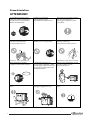
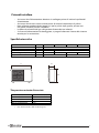
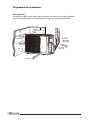
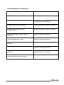
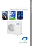
manuale d’installazione
413-HNDCY2-18
413-HNDCY2-24
413-HNDCY3-24
413-HNDCY4-28
Manuale 2
Gentile Cliente,
nel ringraziarla per la Sua scelta: il climatizzatore che ha acquistato le darà per anni un
servizio efficiente, assicurandoLe il massimo comfort senza causarLe alcun problema.
Questo è un apparecchio di elevata tecnologia ed è stato costruito secondo massimi
standard qualitativi.
In questo libretto troverà la descrizione del funzionamento e dei comandi del Suo climatizzatore, affinchè Lei possa ottenere le migliori prestazioni e per informarla sulle
semplici operazioni di manutenzione periodica.
Sperando di aver fatto cosa gradita,
Dianflex La ringrazia e La saluta cordialmente.
Dianflex srl
S.S. 19 Km 61
84030 Atena Lucana - Italy
www.dianflex.com
CONTATTI ASSISTENZA TECNICA E DIR. TECNICA:
e-mail [email protected]
Fax 0975 779333
Versione 10/03 DC Inverter 2011
Questo prodotto è stato distribuito dalla
INDICE
2008 DC-Inverter Italiano Pag. 3
Le istruzioni
prima dell’uso
Prima
di installare.........................................................................................................................................4
4
Nomi di ogni parte
6
Telecomando - pulsanti e funzioni principali
7
Modelli e specifiche tecniche ........................................................................................................................5
INDICE
Temperature
esterne
d’esercizio....................................................................................................................
5
Telecomando
- modalità
di funzionamento
9
Cura e manutenzione
13
Risoluzione dei problemi
14
Installare
l’unità esterna................................................................................................................................8
Installazione
16
Collegamento elettrici...................................................................................................................................6
USO E MANUTENZIONE
! Prima dell’utilizzo ................................................................................................
Installazione
unità interna
! Specifiche
e dati tecnici.......................................................................................
Diagramma
d’installazione............................................................................................................................9
! Nome e funzione di ogni parte ...........................................................................
Installazione
unità esterna
! Funzionamento
del telecomando........................................................................
!
Pulizia
e manutenzione ......................................................................................
Controlli dopo l’installazione........................................................................................................................
10
! Risoluzione dei problemi.....................................................................................
18
20
INSTALLAZIONE
Gentile
Cliente,
! Note per l’installazione .......................................................................................
! Schema
di installazione
dimensioni............................................................
desideriamo
ringraziarla
perdelle
la Sua
scelta: il cimatizzatore che ha acquistato le darà
! Installazione unità interna....................................................................................
per anni
un servizio
efficiente,
assicurandoLe il massimo comfort senza causarLe alcun
! Installazione
unità
esterna...................................................................................
!
Controllo
e
test
di
funzionamento
problema. Questo è un apparecchio.......................................................................
di elevata tecnologia ed è stato costruito secon! Manutenzione .....................................................................................................
do i massimi standard qualitativi. In questo libretto troverà la descrizione del funzionamento e dei comandi del Suo climatizzatore, affinché Lei possa ottenere le migliori
prestazioni e per informarLa sulle semplici operazioni di manutenzione periodica.
Sperando di aver fatto cosa gradita, Dianclima La ringrazia e La saluta cordialmente.
Il prodotto in questo manuale potrebbe essere differente dal reale.
Questo apparecchio non deve essere usato da persone con ridotte capacità fisiche (inclusi bambini) o mancanza
di esperienza e conoscenza, a meno ché non abbiamo una supervisione di persone responsabili della sicurezza.
SMALTIMENTO DI APPARECCHIATURE ELETTRICHE ED ELETTRONICHE OBSOLETE
(DIRETTIVA 2002/96/EC – WEEE)
Questo simbolo indica che il prodotto non deve essere smaltito come un rifiuto domestico. Deve essere
invece consegnato all’apposito centro di raccolta per il riciclo di apparecchiature elettriche ed elettroniche. Il
corretto smaltimento del prodotto evita potenziali conseguenze nocive sull’ambiente e sulla salute. Il riciclo dei
materiali consente di preservare le risorse naturali. Per ulteriori informazioni sul riciclaggio di questo prodotto,
contattare gli uffici del comune di appartenenza, il servizio per lo smaltimento dei rifiuti domestici o il
rivenditore/installatore presso il quale è stato acquistato il prodotto. Il non rispetto di tali modalità di smaltimento
prevede sanzioni così come previsto dalle disposizioni di legge locali.
!
!
!
capacity. The unit will be turned on or
center
. a burning
TIONS
BEFORE
USE smell
protection
When
having
contact
with
the service
damaged, change them by
GENERAL
and assure
it has
enough
cable
signal
control
wire
Never
cutINFORMATION
off orwere
damage power
The power
supply
must
off according
toadopt
your and
requirement
capacity.
The
unit
will
be
turned
on
or
damaged, change
themcontrol
by professional
r smoke, please turn off the power
cables and
wires. If the power
the special circuit that with air switch
WARNINGautomatically, please do not turn on
THE
INSTRUCTIONS
BEFORE
USE
GENERAL
off according
to your
protection
andrequirement
assure it has enough
cable
and
signalINFORMATION
control
wire were INFO
INSTRUCTIONS
BEFORE
USE
upply THE
andTHE
contact
with the service
GENERAL
INSTRUCTIONS
BEFORE
USE
GENERAL
INFORMATION
or turn off the unit frequently, otherwise
ng a burning smell
cut
off or damage
power
automatically,
pleaseThe
dounit
not
turnbeon
The power
supply
must
adopt
capacity.
will
turned onNever
or
damaged,
change them
by professional
center .
THE
INSTRUCTIONS
BEFORE
USE
GENERAL
INFORMATION
THE
INSTRUCTIONS
BEFORE
USE disadvantage effect may be caused
GENERAL
INFORMATION
e turn off the power
cables and control wires. If the power
special
circuit
that
with airto switch
or turn off
the
frequently,
otherwise
off unit
according
your requirement
Prima dithe
installare
WARNING
ATTENZIONE!
toplease
the
unit.
If the
abnormity still
exists,
theautomatically,
unit
protection
and
assure
has
enough
disadvantage
effectitWARNING
may
be
caused
do notcable
turn on
and Never
signal cut
control
wire
were power
act
with the
service
a burning
smell
off or
damage
The power supplyWARNING
must adopt
unit
willoff
bethe
turned
on or
be the
damaged,
and
cause
to may
theThe
unit.
rmity stillmay
exists,
unit capacity.
or turn
unit
frequently,
otherwise
damaged, change them by professional
WARNING
WARNING
urn off theWhen
power
cables
and Never
control
the power
power
the
special
circuit that
with
air
switch
having
a burning
smell
cut wires.
off or
TheThe
power
supply
must
adopt
When
having
a
burning
smell
Never
cut
offdamage
orIfdamage
power
power
supply
must
adopt Non tagliare
off
according
to
your
requirement
Seshock
avvertite
Installare effect
un interruttore
il cavo d’alimentazione
electric
fire.di bruciato o disadvantage
may be caused
maged, and
may
cause orodore
WARNING
having
aturn
burning
smell
Never
cut
off or dama
The
power
supply
must
adopt
or When
smoke,
please
turn
off
the
power
cables
and
control
wires.
If the
power
special
that
withwith
air
switch
When
having
a burning
smell
Never
cut
off
orwires.
damage
power
protection
and the
assure
itcircuit
has
enough
The
power
supply
must
or smoke,
please
off
the
power
cables
and
control
If the
power
the
special
circuit
that
air adopt
switch
or
smoke,
please
turn
offoff
the
power
and
wires.
If the
power
supply
and
contact
with
the
service
the
special
circuit
thatthat
with
air air
switch
or smoke,
please
turn
off
the
power
cables
and
control
wires.
the
special
circuit
that
with
air cables
switch
and
assure
it with
has
enough
or
smoke,
please
turn
the
power
cables
and
control
wires.
Ifwire
the
power
the
special
circuit
switch
cable
and
signal
control
were
supply
and
contact
with
the
service
capacity.
The
unit protection
will
be
turned
on
or
Power
must
adopts
the
special
Never
damage
theIfe
Disconnect
the
power
supply
ifcontrol
damaged,
change
them
by
professional
elettrica
almay
climatizzatore.
d’assistenza.
or
turn
off
the
unit
frequently,
otherwise
may be damaged,
and
cause
capacity.
The
unit
will
be
turned
on
or
protection
and
assure
it
has
enough
damaged,
change
them
by
professional
cable
and
signal
control
wire
were
supply
and
contact
with
the
service
capacity.
The
unit
will
be
turned
on
or
protection
and
assure
it
has
enough
cable and
signal
control
wire
damaged,
change
them
by
professional
supply
andwith
contact
with
theDisconnect
service
center
. the
protection
and ifassure it Never
has enough
must
adopts
the
power
supply
damage
the
electric
wire
orwere control w
cable
and
signal
supply
and
contact
the
service
center
. special
off
according
to according
your
requirement
circuit
prevent
fire.
use
the
electric wire wh
long
putting
the
air conditioner
out change
ofchange
The
unit
will
be
turned
onon
or or damaged,
off
to
your
requirement
disadvantage
effect
may
be
caused
electric shock
ortofire.
them
by by
professional
capacity.
The
will
be
turned
offcapacity.
according
to unit
your
requirement
damaged,
them
professional
cable
and signal
control
were
fuoriuscita
fumo, ainterrompere
magnetotermico
adatto
il cavo
segnale,
seorwire
Whendihaving
burning smell
Never
cut off
damage
power
with the
service
The
power
must
adoptoppure
please
do and
not
turn
onitsupply
toprotection
the unit.
ock
fire.
f theorabnormity
still exists, automatically,
thel’alimentazione
unit
assure
has enough
immediatamente
all’assorbimento
della
macchina.
danneggiati
contattare
il centro
cable and signal
control
wire were
center .
center .
capacity.
The
unit
will
be
turned
on orwire which
revent fire.
long puttingplease
the air
conditioner
of
use
the electric
is not
damaged,
change them by p
off
according
toout
your
automatically,
doaccording
not
turn
on
automatically,
please
do
notrequirement
turn
on on
off
to
your
requirement
to the unit.
still
exists,
automatically,
please
do
not
turn
center
. the unit
appointed.
use.
Power must adopts the special
Disconnect
the
power
supply
ifonon
Never damage the electric wire or
automatically,
please
dootherwise
notnot
turn
off
according
to
your
requirement
automatically,
please
do
turn
or turn
off
the
unitotherwise
frequently,
use.
appointed.
or turn
off the
unit
frequently,
otherwise
or turn
off the unit
frequently,
d, and may cause
or turn
off
the
unit
frequently,
otherwise
or turn
off
the
unit
frequently,
otherwise
disadvantage
effect
may
be be
caused
circuit to prevent fire.
long
putting
the
air
conditioner
out
use on
the electric wire which is not
automatically,
please
doofnot turn
disadvantage
effect
may
caused
disadvantage effect
may
be
caused
fire.
disadvantage
effect
may
be
caused
disadvantage effect may be caused
to
the
unit.
If the
abnormity
still
exists,
the
unit
unit. off the unit frequently, otherwise
If the abnormity still exists, the unit use. to the
appointed.
turn
toorto
the
unit.
If unit
the
abnormity
stillstill
exists,
thethe
unit
to
the
unit.
l exists,
the
the
unit.
If the
abnormity
exists,
unit
may
be
damaged,
and
may
cause
mayspecial
be damaged, and may
cause
adopts the
Disconnect
the power supply if
Never damage the electric wire or
may
bebe
damaged,
and
may
cause
disadvantage effect may be caused
may
damaged,
and
may
cause
electric
shock
or fire.
and may
cause
shock
or fire.
t fire. electric
long
putting
the
air
conditioner
out of
use the electric wire which is not
electric
shock
or
fire.
electric
shock
or fire.the unit
to the unit.
If the abnormity
still
Effettuare
ilexists,
cablaggio
in modo
Scollegare
la macchina se non verrà
Non danneggiare il cavo elettrico e
e.
Power
must
adopts
the
special
Disconnect
the
power
supply
if if utilizzare
Never
damage
the the
electric
wirewire
or or
Power
must
adopts
the
special
Disconnect
the
power
supply
Never
damage
electric
corretto
in
modo
da
evitare
utilizzata
per
un
lungo
periodo.
cavo
adatto
use.
appointed.
Power
must
adopts
thethe
special
Disconnect
thethe
power
supply
if if
Never
damage
thethe
electric
wire
or or
Power
must
adopts
special
Disconnect
power
supply
Never
damage
electric
wire
may be damaged,
and
may
cause
surriscaldamento
dei
cavi.
all’assorbimento
della
macchina.
circuit
to prevent
fire.fire.
longlong
putting
the the
air conditioner
out out
of of useuse
the the
electric
wirewire
which
is not
circuit
to
prevent
putting
air
conditioner
electric
which
is
not
circuit
to prevent
long
putting
thethe
airair
conditioner
outout
of Never
thethe
electric
wire
which
iswire
not or
circuit
fire.
long
putting
of use
use
electric
wire
which
dopts
special
Disconnect
power
supply
ifconditioner
damage
the
electric
Otherwise,
it prevent
can fire.
cause
electric thethe
Otherwise,
will cause o
Otherwise,
the accumulated
itelectric
canthe
cause
electric
Otherwise,
accumulated
dusts
Otherwise,
itdusts
will
cause
overheating
oris itnot
shock
or to
fire.
use.use.
use.
appointed.
appointed.
appointed.
use.
appointed.
cause
fire.
fire.
putting
the overheating
air conditioner
out ofoverheating
use theorelectric
mayorcause
fire. wire which
fire. is not
shock or fire. long may
Power
must
adopts
the special Otherwise, theDisconnect
thedusts
power supply
if
Never
damage the
Otherwise,
it can
cause
electric
accumulated
Otherwise,
it will cause
overheating
or ele
use.
appointed.
cleaning, it isWhen
necessary
Don't attempt to repair the air conditioner
it is necessary
Rated voltagelong
of thisputting
airconditioner
attempt
to repair
Rated
circuit to prevent cleaning,
fire.
thevoltage
air
out of
use theDon't
electric
wire
whic
may cause
overheating
or conditioner
fire.of this airconditioner
fire.
re.
shock or fire.
ving andto turn
the
by yourself.
220-240V,50Hz,The
compressor
stopoffdriving
and turn
off the
by yourself.
220-240V,50Hz,The compressor
use.
appointed.
ply. When cleaning, it is necessary
Don't
attempt
to
repair the air conditioner
will
vibrate
sharply
if
the
voltage
is
conditioner
Rated
voltage
of
this
air
power supply.
will
vibrate sharply
if theitvoltage
is overheating or
n
cause
electric
Otherwise,
the
accumulated
dusts
Otherwise,
will
cause
o stop driving and turn off thetoo low, resulting
by yourself.
220-240V,50Hz,The
in damage compressor
to
it can
cause
electric
Otherwise,
the
accumulated
dusts
Otherwise,
cause
overheating
or or
too
low,
resulting
in damage
toit willititwill
Otherwise,
itcause
can
cause
electric
Otherwise,
the
accumulated
dusts
Otherwise,
will cause
cause
overheating
Otherwise,
it can
electric
the
accumulated
dusts
Otherwise,
overheating
or
may
cause
overheating
or
fire.
fire.
ower Otherwise,
supply.
Cut off power
supplyOtherwise,
refrigerating
system.
Electrical
will
vibrate
sharply
if the voltage
is
may
cause
overheating
or
fire.
fire.
shock
or
fire.
Prima
di
effettuare
la
pulizia
Il
climatizzatore
funziona
con
Non
riparare
il
climatizzatore
da
soli,
may
cause
overheating
fire. Electrical
fire.
maymay
cause
overheating
or system.
fire.
fire.fire.
shock
shock
or fire.
refrigerating
cause
overheating
or or
fire.
shock
or
fire.or fire.
too
in
to
scollegare l’alimentazione
elettrica.
corrente
200-240V
– 50Hz.
chiamare sempre il centro
component
arelow,
easyresulting
toelettrica
damage
ifdamage
ning, it is necessary
Cut off power supply
Don't
to
repair
thetoairrepair
conditioner
conditioner
voltage of Se
thisil voltaggio
air
When
cleaning,
itRated
isit necessary
è troppo
basso
si
può
d’assistenza
Don't
attempt
theair
air air
conditioner
component
are
to attempt
damage
iftecnico.
When
cleaning,
is necessary
Rated
voltage
ofElectrical
this
airconditioner
When cleaning,
it is itnecessary
Don't
attempt
to repair
the
conditioner
conditioner
Rated
voltage
of
this
aireasy
Don't
attempt
to repair
the
cleaning,
is necessary
conditioner
Rated
voltage
ofcompressore
this
air
refrigerating
system.
Don't
attempt
to
repair
theconditioner
air conditioner
conditioner
Rated
voltage
of
this
air
the
voltage
is
too
high.
danneggiare
il
o
altri
and turn offtoWhen
the
by
yourself.
stop
driving
and
turn
off
the
220-240V,50Hz,The
compressor
by
yourself.
220-240V,50Hz,The
compressor
to stopand
driving
and
turn off the
by
yourself.
220-240V,50Hz,The
compressor
to stop
driving
turn
off
the
by yourself.
220-240V,50Hz,The
compressor
to stop driving and Otherwise,
turn off the thecomponent
componenti
elettrici.
byityourself.
theeasy
voltage
is too Otherwise,
high.
220-240V,50Hz,The
compressor
are
to
damage
ifThe wrong
repair
willcause
lead to an
electric
ause electric
accumulated
dusts
will
overheating
or
power
supply.
power
supply. will vibrate sharply ifwill
vibrate
sharply
if the
voltage
is is
the
voltage
is
power
supply.
will
vibrate
sharply
if
the
voltage
power supply.
will will
vibrate
sharply
if
the
voltage
is
The wrong repair will lead
vibrate
sharply
voltage
is
shock
the voltage
islow,
too
high.ifinthe
tootoo
low,
resulting
damage
to to or fire, so you should contact the
may
cause
overheating
or
fire.
fire.
resulting
in
damage
Cut off
supply
too low,
resulting
in
damage
toin damage
Cutpower
off
power
supply
too
low,
resulting
to
e,Otherwise,
it mayCut off
cause
electric
power
supply
too
low, resulting
inaccumulated
damage
to
off power supply
it can causeCutelectric
Otherwise,
the
dusts
Otherwise,
will
ove
Thetowrong
will
lead to
electric
Cut off power supply
refrigerating
system.
Electrical
shock
oritan
fire,
socause
you shoul
service
center
repair.repair
refrigerating
system.
Electrical
refrigerating
system.
Electrical
refrigerating
system.
Electrical
amage.
refrigerating
system.
Electrical
Otherwise, it may cause electric component
areare
easy
to to
damage
if if Don'tshock
g,shock
it is necessary
component
easy
damage
or fire,
so youthe
should
contactto
the
attempt
to repair
air conditioner
service
center
repair.
conditioner
Rated voltage
ofmay
this
air
cause
overheating
fire.
or fire.
component
are
easy
to
damage
if if or fire.
component
are
easy
to
damage
if
component
are
easy
to
damage
Otherwise,
it
may
cause
electric
shock
or
damage.
the voltage
is too
high.
voltage
is too
high.
d turn off the
service center to repair.
by yourself.
220-240V,50Hz,The
compressor
Don't stepthe
on voltage
the the
top
of
outdoor
unit
note whether
the installed
is the
too
high.
Earthing:
The
unit
must
be
reliably
The
wrong
repair
willwill
lead
to an
electric
shock
or
damage.
the
voltage
is
too
high.
the
voltage
is
too
high.
The
wrong
repair
lead
to an
electric to repair the
When cleaning, it is necessary
Don't
attempt
conditioner
Rated
voltage
of
this
air
or
place
something
on
it.
The
wrong
repair
will
lead
to
an
electric
m enough or not.
will
vibrate
sharply
if
the
voltage
is
The
wrong
repair
will
lead
to
an
electric
earthed.
The
earthing
cable
shall
Don't
step
on
the
top
of
the
outdoor
unit
shock
fire,
so
you
should
contact
thethe
The wrong repair
willorlead
toso
anyou
electric
shock
or fire,
should
contact
Pleaseand
note turn
whether
the
installed
Earthing:
The unit mu
to stop driving
off
the
by
yourself.
Otherwise,
it
may
cause
electric
220-240V,50Hz,The
compressor
shock
or
fire,
so
you
should
contact
the the
Otherwise,
it may cause electricDon't step on the top of the outdoor unit
service
center
to
repair.
shock
or
fire,
so
you
should
contact
Please
note
whether
the
installed
Assicurarsi
che
l’unità
sia
fissata
Non
salire
sulla
macchina
o
Collegare
correttamente
la
messa
a
or
place
something
on
it.
be
connected
to
the
special
earthing
service
center
to
repair.
too
low,
resulting
in
damage
to
Earthing:
The
unit
must
be
reliably
stand
is firm
enough
or
not.
shock or fire, so you should contactearthed.
the
Otherwise,
itormay
cause
electric
shock
damage.
Cut
off
power
supply
The earthing
Otherwise,
it may
cause
electricor place
shock
or
damage.
power
supply.
bene.
appoggiare
oggetti
su di essa.
terra.
service
center
to repair.
something
onsharply
it.
service
center
to repair.
stand
is
firm
enough
or
not.
will
vibrate
if
the
voltage
is
may
cause
electric
device
in
the
construction.
earthed.
The
earthing
cable
shall
shock
or damage.
service center to repair.
shock
or damage. refrigerating system. Electrical
be connected to the spec
Don't
step
on
the
top
of
the
outdoor
unit
Please
note
whether
thethe
installed
stepresulting
on the top of the
unit
e.
too Don't
low,
inoutdoor
damage
to
Earthing:
TheThe
unitthe
must
be be
reliably
Please
note
whether
installed
be connected
to
special
earthing
Earthing:
unit
must
reliably
Cut off power supply
component
are easy
to
damage
ifonthe
or or
place
something
it.outdoor
device
in
the construct
Don't
step
on
the
top
of
unit
stand
is
firm
enough
or
not.
place
something
on
it.
Please
note
whether
the
installed
earthed.
The
earthing
cable
shall
Don't step on the top of the outdoor unit
stand
is firm
enough
or not.
Earthing:
The
unit
must
be
reliably
earthed.
The
earthing
cable
shall
Please
note
whether
the installed
device
in
the
construction.
Earthing: The unit must be reliably
refrigerating
system.
Electrical
or place
onunit
it.
Don't
step is
ontoo
the
top
ofsomething
thesomething
outdoor
is firm
enough
or not.
or
place
on it.
be be
connected
tobe
the
special
earthing
the
voltage
high.
The
earthing
cable
shall
whetherstand
thestand
installed
is firm
enough
or not.
connected
to
the
special
earthing
Earthing:earthed.
The
unit
must
reliably
earthed.
The
earthing
cable
shall
component
are
easy
to
damage
if
device
in
the
construction.
or
place
something
on
it.
device
in
the
construction.
be
connected
to
the
special
earthing
ugh or not.
The wrong
repair
will
lead
tospecial
an electric
be
connected
to the
earthing
earthed.
The earthing
cable
shall
Cut off power supply
Otherwise,
it can cause electric
Otherwise, the accumulated dusts
Otherwise, it will cause overheating or
device
in the
construction.
the voltage is too high.
in the
construction.
be connected
todevice
the
earthing
shock or fire,
sospecial
you
should
contact the
The
wrong
repair will lead to
y cause electric
device
in the
construction.
As falling off the outdoor unit can be
service
center
to repair.
ged, it may lead to the
shock or fire, so you should
dangerous.
it and cause the injury.
Otherwise, it may cause electric
unitthe
canoutdoor
be
service center to repair.
Asoutdoor
falling off
unit can be
f it is damaged,
it may lead ittomay
the lead to the As falling off the
If it is damaged,
AsAs
falling
off off
thethe
outdoor
unitunit
cancan
be be
Don't
the top
offalling
the
outdoor
unit
shock
or damage.
If itIfisitdamaged,
it may
lead
to the
outdoor
ther
the installed
is damaged,
it may
lead
tostep
the on
Earthing: The unit must be reliably
dangerous. dangerous.
fall of the unit
and
cause
thedi
injury.
dangerous.
fall of
unit
and
cause
the
injury.
Prima
installare
fallthe
of the
unit
andand
cause
the
injury.
dangerous.
or
place
something
on
it.
fall
of
the
unit
cause
the
injury.
h or not.
As falling
off the
unit unit
can can
be be earthed. The earthing cable shall
If it isIf damaged,
it may
leadlead
to the
As falling
off outdoor
the outdoor
it is damaged,
it may
to the
Don't
step
on
the
top of the outdoor unit
4 note whether the installed
Please
dangerous.
The unit must
fall offallthe
and
cause
the injury.
dangerous.
- and
Assicurarsi
che l’alimentazione
elettrica sia scollegatabe
prima
di iniziare
lespecial
pulizieEarthing:
del
connected
to the
earthing
of unit
the unit
cause
the injury.
or
place
something
on
it.
stand is firm enough
or not.
climatizzatore.
earthed. The earthing ca
As falling off the outdoor unit can be
device in the construction.
may lead to the
- Assicurarsi che le mani siano asciutte prima di iniziare le operazioni di pulizia.
H
Assicurarsi che l’unità sia fissata
bene.
Non salire sulla macchina o
appoggiare oggetti su di essa.
Prima di installare
-
CHNICA
-
P
H
Collegare correttamente la messa a
terra.
Assicurarsi che l’alimentazione elettrica sia scollegata prima di iniziare le pulizie del
climatizzatore.
Assicurarsi che le mani siano asciutte prima di iniziare le operazioni di pulizia.
Non utilizzare prodotti chimici aggressivi per la pulizia tipo gasolio, solventi ecc.
Un panno umido è più che sufficiente.
Installare le tubazioni del gas refrigerante distante dai cavi elettrici.
Se il cavo di alimentazione è danneggiato, si prega di chiamare il centro d’assistenza
tecnico per la sostituzione.
L D AT A
E
GWHD(24)
Prima di installare
tecniche
cal dataSpecifiche
Specifiche tecniche
- Assicurarsi che l’alimentazione elettrica sia scollegata prima di iniziare le pulizie del
city supply
Modelloclimatizzatore.
413HNDCY2-18
HNDCY2-24
HNDCY3-24
HNDCY4-28
- Assicurarsi che le maniVsiano
le operazioni di pulizia.
Alimentazione
~ Hz asciutte prima di iniziare
220-240V~50Hz
40
r air switch
- Non
utilizzare prodottimm
chimici aggressivi per
Sezione
cavi min.
2,5la pulizia tipo gasolio, solventi
4,0 ecc.
Uninterruttore
panno umido
Resistenza
termicoè piùA che sufficiente.
25
40
4.0
um power
cord
section
Installare
le
tubazioni
dai cavi elettrici.
Carica refrigerante (R410A)
gdel gas refrigerante
1400 distante
2400
2200
2200
2
240
- Se ilL-P-H
cavo di alimentazione
si prega di chiamare il centro
d’assistenza
Dimensioni
mm è danneggiato,
818x378x596
890x362x700
ant gas(R410A)
tecnico per la sostituzione.
nd clearance
Specifiche tecniche
L
P
L
Modello
413- esterne d’esercizio
HNDCY2-18
HNDCY2-24
HNDCY3-24
HNDCY4-28
Temperature
Alimentazione
V ~ Hz
220-240V~50Hz
Sezione cavi min.
mm2 DB/WB (°C)
2,5
4,0
Esterne
Resistenza
interruttore termico 48/-A
25
40
Max.
in raffreddamento
H
Carica
(R410A) 10/-g
1400
2400
2200
2200
Min. inrefrigerante
raffreddamento
Dimensioni
L-P-H
mm
818x378x596
890x362x700
Max. in riscaldamento
24/18
P
Min. in riscaldamento
•
-15/-
H
DB = bulbo asciutto – WB = bulbo bagnato
Temperature
esterne
d’esercizio
Temperature esterne
d’esercizio
Max. in raffreddamento
Min. in raffreddamento
Max. in riscaldamento
Min. in riscaldamento
•
Esterne DB/WB (°C)
48/10/24/18
-15/-
DB = bulbo asciutto – WB = bulbo bagnato
UTDOOR UNIT WORKING TEMPERATU
5
Outdoor side DB/WB(
)
Collegamenti elettrici
ELECTRICAL CONNECTIONS
INS TALLER
GWHD(14)NK3BO,GWHD(18)NK3DO,GWHD(24)NK3DO:
- Rimuovere il coperchio posto sul lato destro
Remove the handle at the right side plate of the
dell’unità1. esterna.
outdoor unit (one screw).
modelli 413-HNDCY2-18 / 413- HNDCY2-24
GWHD(14)NK3BO,GWHD(18)NK3DO :
Remove the cable clamp, connect the power connection
Corrente2.elettrica
cable with the terminal at the row of connection and fix
the
connection.
The fitting
line distributing
must be
il ferma
cavo della
morsettiera
(L-N).
1. Aprire
consistent
the indoor unit. terminal of
line bank.
2. Collegare
i filiwith
dell’alimentazione
elettrica
Wiring should meet that of indoor unit.
(+/-) su L – N e quello della messa a terra.
3. Fix power connection wire by wire clamp.
3. Stringere
bene le viti della morsettiera.
has been fixed well.
4. Fissare4.ilEnsure
fermawire
cavo.
5. Install the handle.
Cavo segnali
1. Aprire il ferma cavo delle morsettiere
N(1) – 2 – 3.
An all-pole
disconnection
switch
having
*2 morsettiere
sul dual
– 3 sul
trial
– a4contact
sul
separation of at least 3mm in all pole should be
quadri
connected in fixed wiring.
2. Collegare i fili sulla morsettiera facendo attenWrong wirelaconnection
cause malfunction
of some
zione ne riportare
stessa may
sequenza
di colori
electric components.After fixing cable, ensure that
(esempio: blu
su N(1) interna ed esterna, rosso
leads between connection to fixed point have some space.
su 2 interna ed esterna, marrone su 3 interna ed
esterna. The connection pipes and the connectiong wirings of
the unit A and unit B must be corresponding to each
3. Fissare bene
le viti della morsettiera
other respective.
4. Fissare il ferma cavo.
coperchio
Handle
Pannello
frontale
To
unitAA
Unità
To
unitBB
Unità
L
corrente
elettrica
Power
connecting
cord
segnale
Power
connecting
cord
To the power supply
L
N
L
G W H D ( 24) N K 3D O :
The appliance shall be installed in accordance with
national wiring regulations.
Note: Note: the above figures are only intended to be a simple
diagram
of theai ppliance
and amorsettiere
m y not correspond
- Una volta
fissati
fili sulle
e to the
appearance of the units that have been purchased.
sull’interruttore fare attenzione che essi siano
distanti tra di loro almeno 3 mm.
- Il cablaggio errato potrebbe danneggiare la
macchina.
- I cavi delle unità interne devono corrispondere sulle morsettiere delle unità esterne (unità
interna A sulla morsettiera A e cosi via).
- Il collegamento deve essere effettuato da persone qualificate e secondo le normative in vigore.
Handle
To unit A
To unit B
L
Power
connecting
cord
Power
connecting
cord
To the power supply
L
N
L
5
6
Do not install the outdoor unit where it is exposed
to the sunlight.
Note: the above figures are only intended to be a simple
diagram of theappliance and may not correspond to the
appearance of the units that have been purchased.
Schema di collegamento per il modello 413-HNDCY3-24
coperchio
Handle
Pannello
frontale
To
unitAA
Unità
ELECTRICAL CONNECTIONS
To unit
Unità
B B
To
unitC C
Unità
INS TALLER
L
GWHD(28)NK3BO:
1.Remove the handle at the right side plate of the
outdoor unit (one screw).
Power
interconnection
corrente
segnale
cable
cord
clamp,
connect the power
connection
2.Remove the cable elettrica
segnale
interconnection
cable
cable with the terminal at the row of connection and fix
To the power supply
the connection.
The fitting line distributing must be
cable
connected in fixed wiring.
Wrong wire connection may cause malfunction of some
unità esterna
electric components.
After
Outdoor
unitfixing cable, ensure that
leads between connection to fixed point have
some space.
L
consistent with the indoor unit. terminal
of line bank.
Wiring should meet that of indoor unit.
3. Fix power connection wire by wire clamp.
The connection pipes and the connectiong wirings of
the unit A ,unit B,unit C and unit D must be corresponding
to each other respective.
4. Ensure wire has been fixed well.
unità interna
Indoor unit
5. Install the handle.
An all-pole disconnection switch having a contact
separation
of at least 3mm in all pole should be
interconnection
segnale
The appliance shall be installed in accordance with
national wiring regulations.
Do not install the outdoor unit where it is exposed
to the sunlight.
Schema di collegamento per il modello 413-HNDCY4-28
6
Handle
coperchio
Pannello
frontale
To
unitAA
Unità
To
unitBB
Unità
To
unitCC
Unità
To
unitDD
Unità
L
Power
corrente
cord
elettrica
interconnection
cable
interconnection
cable
interconnection
cable
interconnection
cable
To the power supply
L
unità esternaunit
Outdoor
unità
internaunit
Indoor
HANDLING
After ahvingrem oved the packaging
, check that the contents re
a intact and complet
e.
The outdoor unit
m ust law ays bekept upright.
USER
Handlingm ust be doneby suitab
ly equipped qualifie
d
technical personnel using equipment that isforsuitable
the weight of the appliance.
7
INSTALLING THE OUTDOOR UNIT
INSTALLER
Location
Use bolts to secure the unit to a flat, solid floor.
When mounting the unit on a wall or the roof, make
sure the support is firmly secured so that it cannot
move in the event of intense vibrations or a strong
wind.
Installare l’unità esterna
Avvertenze
Do not install the outdoor unit in pits or air vents
-
NIT
Fissare beneInstalling
l’unitàthe
in pipes
modo da evitare lo spostamento
Use suitable
connecting
and equipment R410A.
for the
Utilizzare tubi rame
adatto
al gaspipes
refrigerante
refrigerant R410A.
Le linee frigorifere non devono superare 10 metri.
The refrigerantdel
pipesgas
mustrefrigerante.
not exceed the maximum
Isolare bene le tubazioni
lengths 10m.
INSTALLER
Installare lo scarico condensa
sull’unità esterna.
Install the drain fitting and the drain hose (for
model with heat pump only)
Condensation is produced and flows from the outdoor unit
when the appliance is operating in the heating mode. In order
not to disturb neighbours and to respect the environment,
install a drain fitting and a drain hose to channel the condensate water. Install the drain fitting and rubber washer on the
dovute
alle
vibrazioni
outdoor unit
chassis
and connect a drain hose to it as shown
in the figure.
Wrap all the refrigerant pipes and joints.
lid floor.
oof, make
it cannot
a strong
Tighten the connections using two wrenches working
Install the drain fitting
and the
drain hose (for
in opposite
directions.
model with heat pump only)
Caution: Installation Must be Performed in Accordance
Condensation is produced and flows from the outdoor unit
with perdita
the NEC/CEC by Authorized Personnel Only.
Vuoto
e
verifica
di
eventuale
when the appliance is operating
in the heating mode. In order
BLEEDING
INSTALLER
not to disturb neighbours
and to respect the environment,
1.
Rimuovere
il dado
di
servizio
dalla
valvola
install
a drain fitting
and
adal
drain
hose
tothe
channel
the circuit
condenHumid
airrubinetto
left
inside
refrigerant
can cause
com- a gas.
pressorfitting
malfunction.
After having
connected
indoor
sate
water. Install
the drain
and pompa
rubber
washer
on the the riferimento
2.
Collegare
i tubi
flessibili
alla
di vuoto,(fate
all’istruzione della pompa di
andconnect
outdoor aunits,
bleed
thetoairit and
humidity from the
outdoor
unit
chassis
and
drain
hose
as
shown
vuoto in possessorefrigerant
esempio
Vedi
fig.
9).
circuit using a vacuum pump.
in the figure.
vents
nt for the
3. Effettuare il vuoto del sistema. Quando il manometro segna la pressione di 1 bar chiudere
and remove the caps from the 2-way and 3il circuito di bassa (1)
edUnscrew
arrestare
la pompa. Verificare per 15 minuti se la pressione è costante
way valves.
maximum
(farà fede all’istruzione
della
dicapvuoto
possesso.
(2) Unscrew
andpompa
remove the
from theinservice
valve.
(3) Connect
the vacuum pump
to the service
valve.
4. Rimuovere il dado
di protezione
dellahose
valvola
del liquido
e del il cavo giallo-verde è
(4) Operate the vacuum pump for 10-15 minutes until an
sempre considerato gas.
absolute vacuum of 10 mm Hg has been reached.
5. Allentare la valvola
delthe
liquido
esagonale
(5) With
vacuum con
pumpuna
still inchiave
operation,
close the fino a che la pressione non
low-pressure
knob
on
the
vacuum
pump
coupling.
Stop
supera 0 bar.
working
the vacuum pump.
6. Rimuovere il tubo
flessibile
dall’estremità
del
(6) Open
the 2-way
valve by 1/4 turn
andrubinetto
then close it e reinserire il dado di protezione.
Vacuum
pump
after 10
Check
the e
joints
for leaks
7. Aprire completamente
laseconds.
valvola
delallgas
quella
delusing
liquido con una chiave
esagonale.
Accordance
soap or an electronic leak device.
8. Rimontare i dadi(7)diliquid
protezione
sulle
valvole
e
poi
verificare
eventuali
perdite.
Turn the body of the 2-way and 3-way valves. Discon-
ersonnel Only.
nect the vacuum pump hose.
(8) Replace and tightenINSTALLER
all the caps on the valves.
Diameter (mm)
se comindoor
rom the
Twisting moment (N.m)
��6
15-20
��9.52
35-40
�� 16
60-65
��12
45-50
��19
70-75
Coppia di serraggio
y and 3-
Diametro del dado (mm) Coppia di serraggio (N.m)
18K unit need
to be installed the indoor unit
Ø6
15-20
Ø 9,52
35-40
valve.
valve.
until an
d.
ose the
ing. Stop
Vacuum pump
18K MODE:
Vacuum pump
(8) Secure
INDOOR
UNIT
Refrigerant fluid direction of flow
2-way valve
3-way valve
(6) Open by 1/4 turn
(7) Turn to open fully
Service
inlet
(2) Turn
(8) Secure
(7) Turn to open fully
(2) Turn
(2) Turn
Valve cap
pompa
del vuoto
Vacuum
pump
Vacuum
pompa
8 del vuotopump
Coppia di serraggio
Discon-
Diametro del dado (mm) Coppia di serraggio (N.m)
Ø6
Ø 9,52
Ø 12
Ø 16
Ø 19
pompa
del vuoto
Vacuum
pump
INDOOR
UNIT
Refrigerant fluid direction of flow
(8) Secure
2-way valve
3-way valve
8
(6) Open by 1/4 turn
(7) Turn to open fully
Service
inlet
(7) Turn to open fully
Valve cap
(8) Secure
Connect to the
indoor unit
conversion joint
close it
ks using
Valve cap
15-20
35-40
40-45
60-65
70-75
nstallation must be done by trained and qualified service personnel
reliability according to this manual.
act service center before installation to avoid the malfunction due to
Diagramma d’installazione
ofessional installation.
n picking up and moving the units, you must be guidedby trained and
Note importanti:
fied person.
L’installazione deve essere fatta secondo questo manuale da personale qualificato.
Per lo spostamento
unità dovete
re that the recommended
space delle
is left
aroundessere seguiti da personale qualificato.
appliance.
GWHD(14)NK3BO,GWHD(18)NK3DO
min 50 cm
50cm or more
Space to the cover
30cm or above
min
30 cm
Space to the cover
30cm or above
min
30side)
cm
(Air inlet
200cm or above
(Air outlet side)
50cm
or above
50 cm50
e più
min
cm
Space
to copertura
the wall
spazio
dalla
min 200 cm
GWHD(24)NK3DO,GWHD(24)NK3EO,GWHD(28)NK3BO
50cm or more
Space to the cover
30cm or above
Space to the cover
30cm or above
(Air inlet side)
200cm or above
(Air outlet side)
50cm or above
Space to the wall
This is just the schematic plan, please refer to the actual product.
9
9
Controlli dopo l’installazione
Cosa verificare
10
Possibile malfunzionamento
E’ stato fissato correttamente?
L’unità potrebbe cadere o emettere rumore.
Hai verificato se ci sono eventuale perdite?
Potrebbe provocare insufficiente capacità di
raffreddamento (riscaldamento).
L’isolamento termico è sufficiente?
Potrebbe provocare condensa e umidità.
Il sistema di drenaggio funziona
correttamente?
Potrebbe provocare condensa e umidità.
Il voltaggio della alimentazione elettrica
rispetta quella indicata sulla targhetta
dell’unità?
Tutti i collegamenti sono stati fatti in modo
sicuro e correttamente isolati?
Potrebbe provocare malfunzionamento
elettrico o danni alla macchina.
E’ stata collegata la messa a terra in modo
corretto?
Potrebbe provocare scosse elettriche.
Il cavo d’alimentazione utilizzato è idoneo?
Potrebbe provocare malfunzionamento
elettrico o danni alla macchina.
Le griglie di entrate e le uscite dell’aria sono
coperte?
Potrebbe provocare insufficienza di
raffreddamento o riscaldamento.
La relazione tra la lunghezza dei tubi e la
capacità del refrigerante sono esatte?
La quantità di refrigerante non è esatta.
Potrebbe provocare malfunzionamento
elettrico o danni alla macchina.
CLIMATIZZATORE D’ARIA
manuale
d’installazione
MANUALE
D’INSTALLAZIONE
CLIMATIZZATORE D’ARIA
Questo prodotto è stato distribuito dalla
dianflex.com