1
ECOTECNA
Carrier
FAN COIL UNITS
Installation manual
VENTILCONVETTORI
Manuale d’installazione
VENTILO-CONVECTEURS
Manuel d’installation
VENTILATOR-KONVEKTOREN
Installationsanweisungen
UNIDADES FAN COIL
Manual de instalación
SURANC
E
AS
Parole chiave: ventilconvettori, fan Coil, riscaldamento,
condizionamento, comandi, kit temperatura, piedini, zoccoli
R QUALIT
TE
Y
Ventilconvettori Carrier
Idrofan 42N
YD'S REGI
S
LO
42N
L
Pr
ez
z
i
eVendi
t
aonl
i
ne
s
u
www.
c
a
l
da
i
ec
l
i
ma
t
i
z
z
a
t
or
i
.
c
om
•
Ca
l
da
i
eVent
i
l
c
onv
et
t
or
i
-Ra
di
a
t
or
i
aGa
s
Condi
z
i
ona
t
or
i
eCl
i
ma
t
i
z
z
a
t
or
i
IS O
900 1
Indice
Contents
page
pagina
Dimensions and weight ....................... 2/3
Dimensioni e masse ............................ 2/3
Operating limits ....................................... 4
Limiti di funzionamento ........................... 4
Electrical data ......................................... 5
Assorbimenti elettrici .............................. 5
Technical data of electric heater ............. 5
Dati tecnici riscaldatore elettrico ............ 5
Material supplied .................................... 5
Materiale a corredo ................................. 5
General information ............................. 6:7
Avvertenze generali ............................. 6/7
Warnings: avoid… ............................. 8/11
Avvertenze: evitare ............................ 8/11
Installation ....................................... 12/15
Installazione .................................... 12/15
Water connections ........................... 16/19
Collegamenti idraulici ...................... 16/19
Electrical connections ..................... 20/21
Collegamenti elettrici ....................... 20/21
Controls ........................................... 22/37
Comandi .......................................... 22/37
Electric heater .................................. 36/37
Riscaldatore elettrico ....................... 36/37
Wiring diagrams ............................... 38/41
Schemi elettrici ................................ 38/41
Maintenance .................................... 42/43
Manutenzione .................................. 42/43
Accessories ..................................... 44/45
Accessori ......................................... 44/45
Unit designation ............................... 46/48
Identificazione unità ......................... 46/48
Dimensions (mm) and weight, cabinet unit / Dimensioni (mm) e masse unità con mobiletto /
Cotes (mm) et poids, unité carrossée / Abmessungen (mm) und Gewicht, Gerät mit
Gehäuse / Dimensiones (mm) y peso, unidad con mueble (instalación vista)
A
249
B
Slots for wall vertical fixing
Condensate discharge Ø 20 mm
O.D. drain connection
Cover panels (accessories)
Supporting feet (accessories)
Slots for horizontal ceiling fixing
249
657
453
168
Asole per fissaggio verticale a
parete
Scarico condensa
Ø esterno 20 mm
Zoccoli (accessori)
Piedi (accessori)
Asole per fissaggio
orizzontale a soffitto
C
Rainures de fixation murale verticale
Raccordement de vidange des condensats
Ø extérieur 20 mm
Panneaux protecteurs (accessoires)
Pieds de support (accessoires)
Rainures de fixation horizontale au plafond
Schlitze für vertikaleWandbefestigung
Kondensatablauf-Anschluss ø 20 mm AD
Abdeckbleche (Zubehör)
Stützfüße (Zubehör)
Schlitze für horizontale Deckenbefestigung
2
Ranuras para fijación vertical sobre pared
Conexión de drenaje de condensado de
Ø 20 mm (exterior)
Paneles de cubrición (accesorios)
Soportes (accesorios)
Ranuras para fijación horizontal en el techo
Índice
Inhalt
Sommaire
page
Seite
página
Cotes et poids ...................................... 2/3
Abmessungen und Gewicht ................. 2/3
Dimensiones y pesos ........................... 2/3
Limites de fonctionnement ...................... 4
Betriebs-Grenzwerte ............................... 4
Límites de funcionamiento ...................... 4
Caractéristiques électriques .................... 5
Elektrische Daten .................................... 5
Datos eléctricos ...................................... 5
Caractéristiques techniques de la
résistance électrique ............................... 5
Technische Daten der Elektroheizung .... 5
Datos técnicos de la resistencia eléctrica . 5
Mitgeliefertes Material ............................. 5
Material suministrado .............................. 5
Allgemeine Informationen .................... 6/7
Información general ............................. 6/7
Vorsicht: vermeiden … ....................... 8/11
Advertencias: evitar ... ....................... 8/11
Installation ........................................ 12/15
Instalación ........................................ 12/15
Wasseranschlüsse ........................... 16/19
Conexiones hidráulicas .................... 16/19
Elektrische Anschlüsse .................... 20/21
Conexiones eléctricas ...................... 20/21
Regelungen ...................................... 22/37
Controles .......................................... 22/37
Elektroheizung ................................. 36/37
Resistencia eléctrica ........................ 36/37
Schaltpläne ...................................... 38/41
Esquemas eléctricos ........................ 38/41
Wartung ............................................ 42/43
Mantenimiento ................................. 42/43
Zubehör ............................................ 44/45
Accesorios ....................................... 44/45
Geräte-Kennzeichnung .................... 46/48
Denominación de la unidad ............. 46/48
Matériel fourni ......................................... 5
Généralités ........................................... 6/7
Attention : éviter… ............................. 8/11
Installation ........................................ 12/15
Branchements d’eau ........................ 16/19
Branchements électriques ............... 20/21
Commandes ..................................... 22/37
Résistance électrique ....................... 36/37
Schémas de câblage ....................... 38/41
Entretien ........................................... 42/43
Accessoires ...................................... 44/45
Désignation de l’unité ....................... 46/48
Dimensions (mm) and weight, concealed unit / Dimensioni (mm) e masse unità da incasso /
Cotes (mm) et poids, unité non carrossée / Abmessungen (mm) und Gewicht, Gerät mit
Gehäuse / Dimensiones (mm) y peso, unidad sin mueble (instalación oculta)
201
164
D
133
42
B
112,5
64
112,5
38
446
168
28,5
42N
kg
Freddo Ø 3/4” GAS Femmina
Caldo Ø 1/2” GAS Femmina
Versione con mobiletto
Versione da incasso
Froid Ø 3/4” gaz femelle
Chauffage Ø 1/2” gaz femelle
Version carrossée
Version non carrossée
P
C
Cool Ø 3/4” gas female
Heat Ø 1/2” gas female
Cabinet version
Concealed version
Kühlung Ø 3/4” - Anschluss
mit Innengewinde
Heizung Ø 1/2” - Anschluss
mit Innengewinde
Gerät mit Gehäuse
Einbaugerät
Ø 20
402
582
28,5
545
618
252
252
453
Frío hembra Ø 3/4” gas
Calor hembra Ø 1/2” gas
Versión instalación vista
Versión instalación oculta
16
25
33
43
50
60
75
A
mm
830
1030
1030
1230
1230
1430
1430
B
mm
332
532
532
732
732
932
932
C
mm
432
632
632
832
832
1032
1032
D
mm
557
757
757
957
957
1157
1157
P
mm
220
220
220
220
220
220
220
kg
17
19
19
22
22
35
35
kg
13
15
15
16
16
28
28
3
Technical data / Dati tecnici / Caractéristiques techniques / Technische Daten / Datos técnicos
Table I: Operating limits
Water circuit
Water-side maximum pressure:
1400 kPa (142 m WG)
Indoor temperature
Mains power supply
Nominal single-phase voltage
Operating voltage limits
Maximum static pressure
Maximum static pressure
(2)
(2)
(versions with centrifugal fan)
(versions with tangential fan)
Minimum entering water temperature: +2°C
Maximum entering water temperature: +80°C
Minimum temperature: 5°C (1)
Maximum temperature: 32°C
230V ~ 50Hz
min. 198V – max. 264V
60 Pa (size 16) - 70 Pa (sizes 25 - 33 - 43 - 50 - 60 - 75)
15 Pa
(1)
Notes
: If the outdoor temperature can go down to 0°C, it is advisable to empty the water circuit to avoid damage caused by ice (see paragraph “water connections”).
: Maximum static pressure values refer to unit operating at high speed for air treatment without dehumidification.
When dehumidification is used, the maximum static pressure is reduced by 5 Pa.
(2)
Tabella I: Limiti di funzionamento
Circuito acqua
Pressione massima lato acqua:
1400 kPa (142 m c.a.)
Temperatura interna
Alimentazione elettrica
Tensione nominale monofase
Tensioni limite di funzionamento
Pressione statica massima
Pressione statica massima
Note
(2)
(2)
(versioni con ventola centrifuga)
(versioni con ventola tangenziale)
Temperatura minima acqua entrante: +2°C
Temperatura massima acqua entrante: +80°C
Temperatura minima: 5°C (1)
Temperatura massima: 32°C
230V ~ 50Hz
min. 198V – max. 264V
60 Pa (grandezza 16) - 70 Pa (grandezze 25 - 33 - 43 - 50 - 60 - 75)
15 Pa
(1)
: Se si prevede che la temperatura ambiente possa scendere sotto 0°C, si raccomanda si svuotare l’impianto acqua onde evitare possibili rotture
da gelo (vedere paragrafo “Collegamenti idraulici).
(2)
: I valori di pressione statica massima si riferiscono all’unità funzionante alla alta velocità per trattamento senza deumidificazione dell’aria.
In presenza di deumidificazione, la pressione statica massima si riduce di 5 Pa.
Tableau I : limites de fonctionnement
Circuit d’eau
Pression maximale côté eau :
1400 kPa (142 m WG)
Température intérieure
Alimentation secteur
Tension monophasée nominale
Tensions de service limites
Pression statique maximale (2) (versions avec ventilateur centrifuge)
Pression statique maximale(2) (versions avec ventilateur tangentiel)
Température minimale de l’eau à l’entrée : +2°C
Température maximale de l’eau à l’entrée : +80°C
Température minimale : 5°C (1)
Température maximale : 32°C
230V ~ 50Hz
min. 198V – max. 264V
60 Pa (taille 16) – 70 Pa (tailles 25 – 33 – 43 – 50 – 60 – 75)
15 Pa
Notes(1) : lorsque la température extérieure est susceptible de tomber à 0°C, il est préférable de vider le circuit d’eau pour éviter les dommages causés par le
gel (voir paragraphe “Branchements d’eau”).
(2)
: Les valeurs maximales de la pression statique s’appliquent à une unité fonctionnant à vitesse élevée pour un traitement de l’air sans
déshumidification. Si la fonction de déshumidification est utilisée, la pression statique maximale est réduite de 5 Pa.
Tabelle I: Betriebs-Grenzwerte
Wasserkreislauf
Wasserseitiger Maximaldruck:
1400 kPa (142 m WS)
Mindest-Wassereintrittstemperatur: +2°C
Maximale Wassereintrittstemperatur: +80°C
Mindesttemperatur: 5°C (1)
Maximaltemperatur: 32°C
230V ~ 50Hz
min. 198V – max. 264V
Raumtemperatur
Netzstromversorgung
Max. statischer Druck
Max. statischer Druck
Anmerkungen
(1)
(2)
(2)
(2)
Einphasige Nennspannung
Betriebsspannungsbereich
(mit Radialventilator)
(mit Querstromventilator)
60 Pa (Größe 16) - 70 Pa (Größe 25 - 33 - 43 - 50 - 60 - 75)
15 Pa
: Kann die Außentemperaur auf den Gefrierpunkt abfallen, sollte der Wasserkreislauf entleert werden, um Frostbeschädigung zu
vermeiden (siehe Abschnitt „Wasseranschlüsse“).
: Die maximalen statischen Druckwerte beziehen sich auf ein Gerät mit hoher Drehzahl für Klimatisierung ohne Entfeuchtung. Wird
Entfeuchtung verwendet, wird der maximale statische Druck um 5 Pa gesenkt.
Tabla I: Límites de funcionamiento
Circuito hidráulico
Presión máxima hidráulica:
1400 kPa (142 m CA)
Temperatura interior
Alimentación eléctrica
Presión estática máxima
Presión estática máxima
Notas
Tensión nominal monofásica
Límites de tensión en funcionamiento
(2)
(2)
(versiones con ventilador centrífugo)
(versiones con ventilador tangencial)
Temperatura mínima de entrada de agua: +2°C
Temperatura máxima de entrada de agua: +80°C
Temperatura mínima: 5°C (1)
Temperatura máxima: 32°C
230V ~ 50Hz
min. 198V – max. 264V
60 Pa (tamaño 16) - 70 Pa (tamaño 25 - 33 - 43 - 50 - 60 - 75)
15 Pa
(1)
: Si la temperatura exterior puede bajar por debajo de 0ºC, es aconsejable vaciar el circuito hidráulico para evitar los daños producidos por el hielo
(ver el apartado «conexiones hidráulicas»).
(2)
Los valores de presión estática máxima hacen referencia al funcionamiento de la unidad a velocidad alta para el tratamiento del aire sin
deshumidificación. Si se utiliza deshumidificación la presión estática máxima se reduce en 5 Pa.
4
Technical data / Dati tecnici / Caractéristiques techniques / Technische Daten / Datos técnicos
Table II: Electrical data (fan motor) / Tabella II: Assorbimenti elettrici (motore ventilatore) /
Tableau II : caractéristiques électriques (moteur du ventilateur) / Tabelle II: Elektrische
Daten (Ventilatormotor) / Tabla II: Datos eléctricos (motor del ventilador)
Current drawn / Corrente assorbita / Intensité absorbée / Stromverbrauch /
Corriente consumida
42N
16
25
33
43
50
60
75
A
A
0,15
0,14
0,32
0,19
0,35
0,22
0,35
0,26
0,44
0,30
0,50
—
0,86
—
Power input / Potenza assorbita / Puissance absorbée / Leistungsaufnahme /
Potencia consumida
42N
16
25
33
43
50
60
75
W
W
32
32
79
33
85
46
73
60
100
69
115
—
195
—
centrifugal fan
tangential fan
centrifugo
tangenziale
Ventilateur centrifuge
Ventilateur tangentiel
Radialventilator
Querstromventilator
Ventilador centrífugo
Ventilador tangencial
Table III: Technical data of electric heater / Tabella III: Dati tecnici riscaldatori elettrici /
Tableau III : caractéristiques électriques de la résistance électrique / Tabelle III: Technische
Daten der Elektroheizung / Tabla III: Datos eléctricos de la resistencia eléctrica
42N
16
A
25 - 33
W
A
W
43 - 50
A
W
60 - 75
A
W
2,17
500
4,34
1000
6,52
1500
6,52
1500
4,34
1000
8,69
2000
13,04
3000
13,04
3000
2,5 (mm2)
2,5 (mm2)
2,5 (mm2)
2,5 (mm2)
Low capacity
High capacity
Power supply cables
Bassa potenza
Alta potenza
Cavi di alimentazione
Faible puissance
Haute puissance
Câbles d’alimentation
électrique
Niedrige Leistung
Hohe Leistung
Stromversorgungskabel
Note: For cable type to be used, see paragraph “Electrical connections”.
Nota: Per la tipologia di cavo da utilizzare, consultare paragrafo “Collegamenti elettrici”.
Note : pour le type de câbles à utiliser, voir le paragraphe “Branchements électriques” .
Anmerkung: Für die zu verwendenden Kabeltypen siehe Abschnitt “Elektrische Anschlüsse”.
Nota: Para el tipo de cable a utilizar, consultar el apartado “Conexiones eléctricas”.
Tab. IV: Materiale a corredo
Table IV: Material supplied
Q.ty
2
2
2
2
1
Description
Brackets for horizontal installation
Fixing screws
Angles to secure filter slides
Screws for cabinet fixing
Installation manual
Q.tà
2
2
2
2
1
Descrizione
Staffe per appensione orizzontale
Viti di fissaggio
Piastrine fermo guida filtro
Viti per fissaggio mobiletto
Manuale di installazione
Tab. IV: Mitgeliefertes Material
Anz.
2
2
2
2
1
Baja potencia
Alta potencia
Sección de los cablesde alimentación
Beschreibung
Halterungen für horizontale Montage
Befestigungsschrauben
Winkel zur Sicherung der Filterschienen
Schrauben zur Gehäusebefestigung
Installationsanweisung
5
Tab. IV : matériel fourni
Q.té
2
2
2
2
1
Description
Supports de montage horizontal
Vis de fixation
Cornières de consolidation des
glissières de guidage du filtre
Vis de fixation de l’unité carrossée
Manuel d’installation
Tabla IV: Material suministrado
Cant.
2
2
2
2
1
Descripción
Estribos para fijación horizontal
Tornillos de fijación
Angulos para fijar las guías del filtro
Tornillos para la fijación del mueble
Manual de instalación
ECOTECNA
Ca
l
da
i
eVent
i
l
c
onv
et
t
or
i
-Ra
di
a
t
or
i
aGa
s
Condi
z
i
ona
t
or
i
eCl
i
ma
t
i
z
z
a
t
or
i
Pr
ez
z
i
eVendi
t
aonl
i
ne
s
u
www.
c
a
l
da
i
ec
l
i
ma
t
i
z
z
a
t
or
i
.
c
om
General information
Avvertenze generali
Unit installation
Installazione dell’unità
Read this instruction manual thoroughly
before using the unit.
• This unit complies with low-voltage
(EEC/73/23 - EN60335-2-40) and
electromagnetic compatibility (EEC/89/336
- EN50081-1 - EN50082-2) directives.
• The installation must be carried out by a
qualified installer.
• Follow all current national safety code
requirements.
In particular ensure that a properly sized
and connected ground wire is in place.
• Check that voltage and frequency of the
mains power supply are those required for
the unit to be installed; the available power
must be adequate to operate any other
appliances connected to the same line.
Also ensure that national safety code
requirements have been followed for the
main supply circuit.
• Where necessary, use field-supplied 20 mm
I.D. PVC pipe (not supplied) of appropriate
length and with the correct thermal
insulation for the condensate drain
extension.
• After installation thoroughly test system
operation and explain all system functions to
the owner.
WARNING:
Disconnect the mains power supply prior
to any maintenance operations or prior to
handling any internal parts of the unit.
• The manufacturer declines any liability from
damage resulting from modifications or errors
in the electrical or hydraulic connections.
Failure to observe the installation instructions,
or use of the unit under conditions other
than those indicated in the table “Operating
limits” of the unit installation manual, will
immediately invalidate the unit warranty.
• Inspect equipment for damage due to
improper transportation or handling: file an
immediate claim with the shipping company.
Do not install or use damaged equipment.
• In case of a malfunction turn the unit OFF
and disconnect the mains supply and
contact a qualified service engineer.
• Maintenance operations must be carried out
by specially trained personnel.
• All of the manufacturing and packaging
materials used for your new appliance
are compatible with the environment and
can be recycled.
• Dispose of the packaging material in
accordance with local requiremements.
Leggere accuratamente questo manuale
prima di procedere all’installazione.
• L’apparecchio è conforme alle direttive
bassa tensione (CEE 73/23 - EN60335-2-40)
e compatibilità elettromagnetica
(CEE 89/336 - EN50081-1 - EN50082-2).
• L’installazione deve essere eseguita da
personale specializzato.
• Eseguire l’installazione rispettando le
normative di sicurezza Nazionali in vigore.
In particolare assicurarsi che sia disponibile
un’efficace linea di messa a terra.
• Controllare che la tensione e la frequenza
dell’impianto elettrico corrispondano a quelle
richieste e che la potenza installata disponibile
sia sufficiente al funzionamento di altri
elettrodomestici collegati sulle stesse linee
elettriche. Assicurarsi che l’impianto
elettrico di alimentazione sia conforme alle
vigenti norme Nazionali per la sicurezza.
• La prolunga del tubo di scarico della condensa
dell’unità interna deve essere eseguito con
un tubo in PVC Ø interno 20 mm (non fornito)
di lunghezza adatta all’installazione prescelta
ed adeguatamente isolato termicamente.
• Dopo l’installazione eseguire il collaudo
funzionale ed istruire l’utente sul corretto
funzionamento del climatizzatore.
ATTENZIONE:
Prima di ogni operazione di manutenzione e
prima di accedere alle parti interne
dell’unità, togliere l’alimentazione elettrica.
• Il costruttore declina ogni responsabilità
per modifiche o errori di collegamento
elettrico ed idraulico. L’inosservanza delle
istruzioni quì riportate o l’utilizzo del
climatizzatore in condizioni diverse da quelle
riportate in Tabella “limiti di funzionamento”
del manuale dell’unità, provocano
l’immediato decadimento della garanzia.
• Assicurarsi che l’unità non abbia subìto
danni durante il trasporto; nel caso esporre
immediato reclamo allo spedizioniere. Non
installare ne utilizzare apparecchi danneggiati.
• In caso di funzionamento anomalo spegnere
l’unità, togliere l’alimentazione elettrica e
rivolgersi a personale specializzato.
• La manutenzione deve essere eseguita
solo da personale qualificato.
• Tutti i materiali usati per la costruzione
e l’imballaggio del climatizzatore sono
ecologici e riciclabili.
• Eliminare il materiale di imballaggio
rispettando le vigenti normative.
Choosing the installation site
Da evitare:
• Posizione soggetta a raggi solari diretti.
• Aree in prossimità di fonti di calore.
• Luoghi umidi e posizioni dove l’unità
potrebbe venire a contatto con acqua (es:
locali adibiti ad uso lavanderia).
• Luoghi dove tende o mobili possano
ostruire la circolazione dell’aria.
Da fare:
• Considerare un’area libera da ostruzioni
che potrebbero compromettere la regolare
mandata e ripresa dell’aria.
• La superficie della parete deve essere piana per
consentire un facile e solido aggancio dell’unità.
Essa dovrà essere inoltre adeguata al peso della
unità. Questo eviterà anche possibili deformazioni,
rotture e vibrazioni durante il funzionamento.
• Considerare un’area dove le operazioni di
installazione siano facilitate.
• Considerare una posizione che rispetti gli
spazi minimi di manutenzione consigliati
(vedi disegno).
• Considerare una posizione che permetta una
buona distribuzione dell’aria nell’ambiente.
• Installare l’unità in modo che l’acqua di
condensa possa facilmente essere
drenata, ad uno scarico adeguato.
Positions to avoid:
• Exposed to direct sun.
• Too close to heat sources.
• On humid walls or positions with water
hazard, e.g. laundry premises.
• Where curtains or furniture may obstruct
free air circulation.
Recommendations:
• Choose an area free from obstructions
which may cause irregular air distribution
and/or return.
• Check that the wall surface is flat enough to
allow easy and safe installation. The wall
structure should be strong enough to carry
the unit weight and avoid deformation,
rupture or vibration during operation.
• Consider using an area where installation is
easy.
• Choose a position that allows for the
clearances required (see drawing).
• Look for a position in the room which
assures the best possible air distribution.
• Install unit in a position where condensate
can easily be piped to an appropriate drain.
6
Scelta del luogo di installazione
Warnings: avoid…
Avvertenze: evitare…
… exposure to direct sunshine, when unit
is operating in cooling mode; always use
shutters or shades.
… in raffrescamento l’irraggiamento
diretto in ambiente: tirare le tende.
… positions too close to heating sources
which may damage the unit.
… luoghi vicini a fonti di calore che
potrebbero danneggiare l’unità.
… connecting condensate piping to sewage
system drain without appropriate trap. Trap
height must be calculated according to the
unit discharge head in order to allow
sufficient and continuous water evacuation.
… tubo scarico condensa in scarico civile/
fognatura senza sifone.
Il sifone deve comunque avere un’altezza
in relazione al bettente disponibile tale da
consentire una corretta evacuazione della
condensa.
… only partial insulation of the piping.
… installation not correctly levelled which
will cause condensate dripping.
… flattening or kinking pipes or condensate
pipes.
10
… isolamento parziale delle tubazioni.
… installazioni non in piano; sono causa di
gocciolamenti.
… lo schiacciamento delle tubazioni di
collegamento e del tubo di scarico
condensa.
160 mm
min.
500 mm
min.
Rotate 180°
Ruotare di 180°
Tourner de 180°
168 mm
min.
Um 180° drehen
Girar 180°
252 mm
100 mm min.
Screw anchor with double screw
Air vent
Tassello ad espansione a vite doppia
Sfiato aria
Cheville d’ancrage à double vis
Purge d’air
Spreizdübel mit Doppelschraube
Entlüftung
50 mm
2% min.
Tornillos de sujección con doble tornillo
Purga de aire
Installation
Installazione
Floor-mounted vertical unit
Installazione unità verticale a
pavimento
The floor mounted unit must be provided
with supporting feet.
• For positioning and drilling use the
template printed on the packaging.
• Drill four holes for the screw anchors.
• Position unit to wall and secure it with
screws.
To facilitate cabinet installation, it is
suggested to use flathead screws.
• To complete the installation make
electrical and water connections as per
the diagram inside the control box panel.
L’unità per il fissaggio a pavimento dovrà
essere provvista di piedi di sostegno.
• Per il posizionamento e la foratura
utilizzare la dima stampata sulla
copertura dell’imballo.
• Eseguire i 4 fori per i tasselli ad espansione.
• Posizionare l’unità a parete e fissarla con
4 viti.
Per facilitare l’installazione del mobile, è
consigliabile utilizzare viti e testa svasata.
• Ultimare l’installazione eseguendo gli
allacciamenti idraulici ed elettrici come da
schema riportato all’interno del quadro
elettrico.
WARNING: With wall-to-wall carpet the
hole points must be moved up by as
indicated on the template.
ATTENZIONE: In presenza di pavimenti con
moquette la foratura dovrà essere spostata
verso l’alto come indicato sulla dima.
Wall-mounted vertical unit
Installazione unità verticale
sospesa a parete
• To position the unit use the template
printed on the packaging.
• Drill four holes for the screw anchors.
• Raise unit at least 100 mm.
Position the upper screws, hook on the
base unit and fix it with 4 screws.
To facilitate cabinet installation, it is
suggested to use flathead screws.
• To complete the installation make electric
and water connections as per the
diagram inside the control box panel.
• Per il posizionamento dell’unità utilizzare la
dima stampata sulla copertura dell’imballo.
• Eseguire le quattro forature per i tasselli
ad espansione.
• L’unità deve essere sollevata dal pavimento
di almeno 100 mm. Predisporre le viti superiori
agganciare l’unità base e fissarla con 4 viti.
Per facilitare l’installazione del mobile, è
consigliabile utilizzare viti e testa svasata.
• Ultimare l’installazione eseguendo gli
allacciamenti idraulici ed elettrici come da
schema riportato all’interno del quadro
elettrico.
Ceiling-mounted horizontal unit
Installazione unità orizzontale a
soffitto
• Use the template printed on the
packaging for ceiling mounting of the
unit.
• Drill four holes for the screw anchors.
• Attach the two brackets supplied for
horizontal installation to the unit,
securing them with the screws as shown
in figure.
• Hook the unit on the screw anchors in
the ceiling and adjust the 4 screws.
• Make certain the fan coil is
horizontally levelled.
• Per il posizionamento dell’unità a soffitto
utilizzare la dima stampata sulla copertura dell’imballo.
• Eseguire le quattro forature per i tasselli
ad espansione.
• Applicare all’unità le due staffe di
appensione provviste a corredo fissandole
con le apposite viti come indicato in figura.
• Agganciare l’unità ai tasselli ad
espansione applicati al soffitto e regolare
la chiusura delle 4 viti.
• Assicurarsi che il ventilconvettore sia
perfettamente livellato in orizzontale.
Condensate drain
Tubazione di scarico condensa
Coil surface condensation formed during
the cooling cycle is collected in a pan
purposely placed under the coil and then
drained out through a drain pipe fitted on
the coil connection side.
A simple flexible tube which fits Ø 20 mm is
recommended.
To facilitate correct condensate draining,
make sure that the drain pipe is not bent or
restricted and that it has the required slope
(at least 2%) along its length.
A drain trap is recommended.
L’acqua di condensa che si forma sulla
batteria durante il raffrescamento viene
raccolta nella bacinella situata sotto la
stessa e convogliata all’esterno tramite un
tubo di scarico situato sul lato attacchi
batteria. Si consiglia un normale tubo
flessibile di Ø 20 mm.
Per favorire il regolare drenaggio dell’acqua di condensa, verificare che il tubo di
scarico non presenti pieghe o strozzature e
che abbia la necessaria pendenza su tutto il
percorso (almeno 2%). È opportuno che gli
scarichi condensa siano sifonati.
Checking
Verifica
Before unit operation verify that the water
flows into the internal condensate drain
pan by pouring some water into it.
If problems are detected, check the drain
pipe slope and look for possible
obstructions.
All’avviamento dell’unità verificare che
l’acqua defluisca regolarmente dalla
bacinella di scarico condensa interna
versando dell’acqua nella stessa. In caso
contrario controllare la pendenza delle
tubazioni e ricercare eventuali ostruzioni.
14
Collegamenti idraulici
Water connections
Space for water connections / Spazi per allacciamenti idraulici / Espace nécessaire pour les
branchements d’eau / Platz für Wasseranschlüsse / Espacio para conexiones hidráulicas
Front view / Vista frontale / Vue de front / Vorderansicht / Alzado
130 mm
Ø 20 mm
196 mm
ECOTECNA
Ca
l
da
i
eVent
i
l
c
onv
et
t
or
i
-Ra
di
a
t
or
i
aGa
s
Condi
z
i
ona
t
or
i
eCl
i
ma
t
i
z
z
a
t
or
i
Pr
ez
z
i
eVendi
t
aonl
i
ne
s
u
www.
c
a
l
da
i
ec
l
i
ma
t
i
z
z
a
t
or
i
.
c
om
IN
OUT
Cool Ø 3/4” gas female
Heat Ø 1/2” gas female
Condensate drain
Auxiliary drain pan
(accessory)
Floor
EIN
AUS
Kühlung Ø 3/4” Anschluss mit Innengewinde
Heizung Ø 1/2” Anschluss mit Innengewinde
Kondensatablauf
Hilfs-Ablaufwanne (Zubehör)
Fußboden
ENTRÉE
SORTIE
Froid Ø 3/4” gaz femelle
Chauffage Ø 1/2” gaz femelle
Bac à condensats
Bac à condensats auxiliaire
(accessoire)
Sol
302 mm
Ø 20 mm
INGRESSO
USCITA
Freddo Ø 3/4” Gas femmina
Caldo Ø 1/2” Gas femmina
Scarico condensa
Bacinella ausiliaria
(accessorio)
Pavimento
Entrada IN
Salida OUT
Frío hembra Ø 3/4” gas
Calor hembra Ø 1/2” gas
Recogida de condensado
Bandeja auxiliar de recogida de condensado
(accesorio)
Suelo
Water piping can enter either from the floor
or from the wall. Leave the space shown in
the figure.
The unit coil can be supplied with water
connections positioned as requested.
However field conversion of the
connections is achieved quite simply as
follows:
• Remove the control box panel;
• Unscrew the 6 self-threading screws and
remove the front drain pan;
• Unscrew the two screws holding the heat
exchanger to the structure, necessary for
earthing the coil;
• Remove the coil by unhooking it with the
rubber tabs and turn it horizontally
through 180°.
• Place the coil into its new position by
hooking it using the special rubber tabs;
• Refit the front drain pan with the 6 selfthreading screws;
• Retighten the two screws holding the
heat exchanger to the structure,
necessary for earthing the coil;
• Position the control box panel opposite
the coil connections.
• Pass the sensor through the special hole
and seal with sealing material in the
tangential fan versions;
• Position the control into the tabs
provided,, blocking it with the supplied
metal plate (see paragraph “Controls”).
NOTE:
The connection pipes must be insulated
with a condensation-proof material such as
polyurethane, propylene or neoprene of 5
to 10 mm thickness.
16
Le tubazioni dell’impianto idrico potranno
arrivare sia da pavimento che da parete
utilizzando gli spazi secondo la figura.
La batteria sull’unità viene fornita con i
collegamenti idraulici posizionati come da
richiesta in fase d’ordine.
E’ comunque possibile invertire in cantiere la
posizione degli attacchi nel seguente modo:
• rimuovere il quadro elettrico;
• svitare le 6 viti autofilettanti e rimuovere
la bacinella anteriore;
• svitare le 2 viti di fissaggio della batteria
alla struttura, necessarie per il collegamento della messa a terra della batteria;
• sfilare la batteria sganciandola per mezzo
delle linguette in gomma e ruotarla
orizzontalmente di 180°;
• posizionare la batteria nella sua nuova
sede agganciandola con le apposite
linguette in gomma;
• rimontare la bacinella anteriore con le 6
viti autofilettanti;
• riavvitare le 2 viti di fissaggio della
batteria alla struttura, necessarie per il
collegamento della messa a terra della
batteria;
• posizionare il quadro elettrico sul lato
opposto agli attacchi della batteria;
• posizionare il sensore di temperatura
nella apposita sede sigillando con stucco
nelle versioni tangenziali;
• inserire il comando nelle apposite
linguette bloccandolo con la staffetta a
corredo (vedi paragrafo “Fissaggio
comando”).
NOTA:
Rivestire i tubi dei collegamenti con del
materiale anticondensa tipo polietilene o
moltoprene espanso di spessore 5-10 mm.
Water connections
Collegamenti idraulici
Automatic water valves
Valvole automatiche di controllo
acqua
The fan coils can be equipped with valves,
both in 2-pipe or 4-pipe versions.
Le unità possono essere equipaggiate con
valvole sia nell’esecuzione due tubi che
quattro tubi.
Le teste delle valvole sono del tipo ad
azionamento termico alimentate a 230V,
consumo medio 5 VA, la massima
pressione di lavoro è di 1600 kPa.
Il tempo di apertura dipende dalla
temperatura ed è pari a 120-240 secondi.
La tenuta dei raccordi alle valvole è
garantita da una guarnizione in gomma
(o-ring) inserita nel raccordo (coppia di
serraggio 24,5 Nm).
L’accessorio valvole automatiche può inoltre
essere fornito con rubinetto e detentore
per la regolazione del flusso d’acqua e per
l’esclusione dell’unità dall’impianto.
Le valvole automatiche possono essere a
tre vie con by-pass o a due vie.
Per il collegamento dei tubi dell’impianto
assicurarsi che siano allineati e supportati
in modo da non esercitare sforzi anomali
sull’unità.
Quando l’impianto viene riempito con
acqua verificare la tenuta di tutti i raccordi.
Ricordarsi di montare la bacinella
ausiliaria sotto il gruppo valvole inserendo
il tubetto di scarico nell’apposito foro.
La casa costruttrice non può garantire
l’efficienza di tenuta dei gruppi valvole
forniti dall’installatore e perciò non
collaudati in fabbrica.
Declina pertanto ogni responsabilità per
eventuali malfunzionamenti degli stessi e
per danni derivanti da gocciolamento
dovuto a quanto sopra detto.
The valve heads are thermal type with
230V power supply, average consumption
5 VA, maximum operating pressure
1600 kPa.
The opening time depends on the
temperature and is from 120 to 240 seconds.
The tightness of the connections is
ensured by a rubber sealing (“O-ring”)
inserted in the connection (tightening
torque 24.5 Nm).
The accessory motorized valve can also be
supplied with a shut-off valve and holder
for water flow control and for unit
disconnection from the system.
The motorized valves can be 3-way with
bypass or 2-way.
Make sure that all unit pipe connections
are aligned and well supported, to prevent
abnormal strains on the unit.
Check for leaks after the system has been
filled with water.
Remember to mount the auxiliary drain pan
under the valve group inserting the drain
pipe into the proper hole.
The manufacturer cannot guarantee seal
quality and tightness of the valve group
provided by the installer (which is therefore
not factory tested).
The manufacturer thus declines all
responsibility for possible malfunction of
said items and for damage resulting from
leaks in said items.
18
Electrical connections
Collegamenti elettrici
Control box panel in metal sheet for versions without electric heater / Quadro elettrico in
metallo per versioni senza riscaldatore elettrico / Panneau métallique du boîtier de
commande pour les versions sans résistance électrique / Schaltkasten-Abdeckung aus
Blech für Ausführungen ohne Elektroheizung / Cuadro eléctrico con revestimiento metálico
para las versiones sin resistencia eléctrica
Legend:
8
7
6
5
L
N
4
3
2
1
Control connection cable
Motor connection cable
Power supply cable (230V ~)
Accessory connections (valves - remote contact - heaters)
Fan motor capacitor
Cable holder
Terminal block for electric heater power supply
Electric heater relay
Legenda:
Cavo collegamento comando
Cavo collegamento motore
Cavo alimentazione (230V ~)
Collegamento accessori (valvole - contatto remoto - riscaldatori)
Condensatore motore ventilatore
Fermacavo
Morsettiera alimentazione riscaldatore elettrico
Relè riscaldatore elettrico
IMPORTANT:
• Make earth connection prior to any
other electrical connections.
• Disconnect the power supply to all
circuits prior to handling any electrical
components.
IMPORTANTE:
• Eseguire il collegamento di messa a
terra prima dei collegamenti elettrici.
• Togliere l’alimentazione elettrica a tutti i
circuiti prima di accedere alle parti elettriche.
• Before proceeding with the unit
connection to the mains supply locate live
L and neutral N, then make connections
as shown in the wiring diagram.
• Ensure that the mains supply connection
is made through a switch that disconnects
all poles, with contact gap of a least 3 mm.
• The fan coil connecting cable as well
as accessory wires must be H07 RN-F
type (or higher), synthetic rubber
insulation with Neoprene coating,
according to EN 60335-2-40 and
HD277.S1 codes and located in a
proper rigid conduit.
• For the unit power supply, it is
recommended to use cables with a
minimum size of 1.5 mm 2.
• For units equipped with electric heater,
refer to table III (Technical data of
electric heater) for sizing power supply
cables.
• Prima di collegare il cavo all’alimentazione elettrica, individuare la linea L ed il
neutro N, quindi eseguire i collegamenti
come indicato sullo schema elettrico.
• Assisurarsi che il collegamento alla rete
elettrica sia effettuato attraverso un
interruttore onnipolare con apertura dei
contatti di almeno 3 mm.
• Tutti i cavi di collegamento con il
ventilconvettore, inclusi i relativi
accessori, devono essere di tipo H07 RN-F
(o superiore), con isolamento in gomma
sintetica e guaina in policloroprene, in
accordo alle norme EN 60335-2-40 e
HD277.S1 e posizionati sotto traccia.
• Per l’alimentazione elettrica dell’unità,
si raccomanda di utilizzare cavi di
sezione minima di 1,5 mm 2.
• Per le unità equipaggiate di riscaldatore
elettrico, fare riferimento alla tabella III (Dati
riscaldatori elettrici) per l’esatto
dimensionamento dei cavi
dell’alimentazione elettrica.
Control box panel
Quadro elettrico
The control box panel is always
positioned opposite the water
connections.
• Two different control box panels are available:
one for a unit without electric heater, and
one for a unit with electric heater. Inside
each control box panel there is a terminal
block for the electrical connections (see
wiring diagrams). After connections have
been completed, cables must be secured
with the cable holders supplied.
• If the unit is fitted with an electric
heater, this must have a separate
power supply.
Il quadro elettrico si trova sempre
posizionato dalla parte opposta a quella
degli attacchi idraulici.
• Sono disponibili due tipi di quadro elettrico,
uno per unità senza riscaldatore elettrico,
l’altro per unità con riscaldatore elettrico.
All’interno di ogni quadro elettrico è presente
una morsettiera alla quale effettuare i
collegamenti elettrici (vedi schemi elettrici).
Eseguire i collegamenti alla morsettiera e
bloccare i cavi con gli appositi fermacavi.
• Se l’unità è equipaggiata di riscaldatore
elettrico quest’ultimo deve essere
alimentato separatamente dall’unità.
20
Comandi
Controls
Control type “A”
Comando tipo “A”
Commande type “A”
Regelungstyp “A”
Control tipo “A”
Control type “U”
Comando tipo “U”
Commande type “U”
Regelungstyp “U”
Control tipo “U”
Control type “B”
Comando tipo “B”
Commande type “B”
Regelungstyp “B”
Control tipo “B”
20°c
20°c
TO
AU
ECOTECNA
Ca
l
da
i
eVent
i
l
c
onv
et
t
or
i
-Ra
di
a
t
or
i
aGa
s
Condi
z
i
ona
t
or
i
eCl
i
ma
t
i
z
z
a
t
or
i
Pr
ez
z
i
eVendi
t
aonl
i
ne
s
u
www.
c
a
l
da
i
ec
l
i
ma
t
i
z
z
a
t
or
i
.
c
om
F
OF
AU
F
OF
F
OF
TO
A
Upon request, the 42N series fan coil can
be equipped with one of three types of
controls: one electromechanical and two
electronic versions, regulated by a
microprocessor.
With these last two control types,
temperature control in each single room,
heated or cooled by 2 or 4-pipe fan coils, is
via a microprocessor located in the
controller.
This high-tech solution allows energy
savings and optimum comfort levels.
All three controls can be mounted either on
the fan coil or on the wall.
Each control regulates a single fan coil
(alternatively with a relay board it is
possible to regulate several units with a
single control (see accessories).
All controls must be opened and
installed only by qualified personnel as
they contain electrical and electronic
components, connected to 230V power
supply.
I ventilconvettori della serie 42N, a
richiesta possono essere equipaggiati con
uno dei tre tipi di comando disponibili.
Di questi, uno è di tipo elettromeccanico e
due di tipo elettronico con regolazione a
microprocessore.
Con questi ultimi due tipi di comando, la
regolazione della temperatura nei singoli
ambienti riscaldati o raffrescati da
ventilconvettori a 2 e 4 tubi, viene gestita
dal microprocessore presente nei controlli.
Questa soluzione di elevato contenuto
tecnologico permette di ottenere un
risparmio energetico ed un livello di
comfort ottimali.
I tre modelli di comando possono essere
montati sia a bordo macchina che a parete.
Ogni comando è in grado di controllare un
solo ventilconvettore (opzionalmente
mediante una scheda ausiliaria è possibile
comandare più ventilconvettori con un
unico comando (vedi accessori).
I comandi devono essere aperti ed
installati solo da personale
specializzato in quanto al loro interno i
componenti elettrici ed elettronici sono
collegati alla tensione di 230V.
WARNING:
• Disconnect the power supply before
opening the control cover.
• All inputs (external contact, seasonal
changeover etc.) must be electrically
insulated consistent with 230V
requirements.
ATTENZIONE:
• Togliere l’alimentazione elettrica prima
di aprire il coperchio del comando.
• Tutti gli ingressi (contatto esterno,
cambio stagionale ecc.) devono essere
adeguatamente isolati per la tensione
di 230V.
22
Comandi
Controls
Control functions
Caratteristiche comandi
ON/OFF
ACCESO/SPENTO
Three fan speeds manually selected
Tre velocità ventilazione manuale
Fan speed automatically selected
Velocità ventilazione automatica
Temperature selector
Selettore temperatura
Green LED – cooling operation
LED verde funzione raffrescamento
Red LED – heating operation
LED rosso funzione riscaldamento
Yellow LED – automatic seasonal changeover
LED giallo funzione cambio stagionale automatico
Yellow LED – energy saving
LED giallo funzione “energy saving” (risparmio energetico)
Manual seasonal changeover button
Pulsante cambio stagionale manuale
Centralised seasonal changeover button
Pulsante cambio stagionale centralizzato
Automatic seasonal changeover button
Pulsante cambio stagionale automatico
Energy saving button
Pulsante funzione “energy saving” (risparmio energetico)
Return air temperature sensor
Sensore temperatura ripresa aria
Temperature sensor located on the board
Sensore temperatura a bordo scheda
Cooling / heating valve (2-pipe)
Valvola raffrescamento/riscaldamento (2 tubi)
Heating valve (4-pipe)
Valvola riscaldamento (4 tubi)
Cooling valve (4-pipe)
Valvola raffrescamento (4 tubi)
Electric heater
Riscaldatore elettrico
Frost-protection
Funzione antigelo (frost-protection)
External contact
Contatto esterno
Water temperature sensor
Sensore temperatura acqua
Air sampling (periodic fan starting)
Air sampling (avviamento temporizzato del ventilatore)
Continuous ventilation
Ventilazione continua
Temperature block
Blocco temperatura
Autotest
Autotest
Type U
Tipo U
Type A
Tipo A
Type B
Tipo B
24
Controls
Comandi
Type “U” control
This is an electromechanical control with a
4 position knob for unit OFF and fan speed
regulation (OFF - V1 - V2 - V3).
This control cannot be used for room
temperature adjustment.
Comando tipo “U”
Questo comando è di tipo
elettromeccanico, dotato di commutatore
rotativo a 4 posizioni per spegnimento e
regolazione della velocità di ventilazione
(OFF - V1 - V2 - V3).
Non sono previste funzioni di regolazione
della temperatura interna.
Type “A” and “B” control
Type “A” control is used in 2-pipe systems.
Type “B” control is used in 4-pipe systems
and 2-pipe systems with electric heater.
Comando tipo “A” e “B”
Il comando di tipo “A” viene utilizzato negli
impianti a 2 tubi.
Il comando di tipo “B” viene utilizzato negli
impianti a 4 tubi e 2 tubi con riscaldatore
elettrico.
Functions
(type “A” and “B” controls)
Funzioni
(comandi “A” e “B”)
Type “A” and “B” controls have a knob to
select the temperature, with a range from
10°C to 30°C, and room temperature is
maintained at the selected value.
I comandi di tipo “A” e “B” provvedono a
mantenere la temperatura interna
impostata dalla manopola tra 10°C e 30°C.
Fan operation
With the fan speed selector , fan mode
can be set either manually or automatically.
In the manual mode it is possible to select
three fan speeds (low/ medium/high)
according to personal preference.
In the auto mode fan speed is regulated by
a microprocessor in the control in relation
to the temperature chosen.
During installation, it is possible to select
continuous fan operation via the switch
located on the electronic board (see
paragraph “Dip-switch configuration”).
Fan operation during heating mode is
delayed by one minute to allow for
dispersion of residual heat present on
the heat exchanger coil or on the
electric heater if installed (only for type
“B” control).
As an option (only for type “A” control), fan
operation can be disabled during heating,
via a sensor on the water piping, if the
water temperature is below 40°C and
during cooling if the water temperature is
above 18°C.
These two functions allow improved
comfort levels during winter by avoiding
undesired fan operation and during
summer by turning the fan coils ON and
OFF automatically in relation to the water
temperature.
Frost-protection
This function keeps the temperature from
dropping below 7°C in rooms not used for
long periods of time.
When this temperature is reached and with
the frost protection function activated by a
dip-switch (set during installation) located
on the electronic board (see paragraph
Dip-switch configuration) the control
activates the valve(s) and puts the fan on
high speed. The frost protection function, if
enabled, is activated even when the control
is in the OFF position.
26
Ventilazione
Tramite il selettore della velocità del
ventilatore è possibile scegliere in modo
manuale o automatico la modalità di
funzionamento del ventilatore.
In modalità manuale è possibile scegliere
tre tipi di velocità (bassa/media/alta) in
funzione delle proprie necessità.
In modalità auto la velocità del ventilatore
è regolata dal microprocessore del
comando in funzione della temperatura
scelta.
Durante l’installazione è tuttavia possibile
selezionare la ventilazione continua,
agendo sui “dip-switch” (microinterruttori)
presenti sulla scheda elettronica (vedere
configurazione dip-switch).
La ventilazione in modalità riscaldamento
viene ritardata di circa un minuto per
permettere lo smaltimento del calore
residuo presente sulla batteria di scambio
termico o sui riscaldatore elettrico se
installati (solo comando tipo “B”).
Opzionalmente (solo per comando tipo “A”)
è prevista la possibilità, tramite un sensore
posto sulla tubazione dell’acqua, di
escludere la ventilazione, in modalità
riscaldamento se la temperatura dell’acqua è
inferiore a 40°C e nella modalità
raffrescamento se superiore a 18°C.
Queste due funzioni permettono di ottenere
un maggior comfort durante il funzionamento
invernale evitando ventilazioni indesiderate,
mentre in modalità estiva consentono lo
spegnimento e l’accensione in modo
automatico di tutti i ventilconvettori in
funzione della temperatura dell’acqua.
Antigelo
La funzione antigelo permette di evitare in
ambienti non frequentati per lunghi periodi
che la temperatura scenda sotto 7°C.
Raggiunta questa temperatura con antigelo
inserito in fase di installazione tramite “dip
switch” presente sulla scheda elettronica
(vedi paragrafo configurazione dip-switch)
il controllo provvede ad attivare la/e
valvola/e e il ventilatore alla alta velocità.
La funzione antigelo se abilitata è attiva
anche con il comando in posizione OFF.
Controls
Comandi
Energy saving
This function is especially useful when air
conditioning at night or in rooms where the
user is likely to be absent for a longer
period of time.
In this case, pushing button raises the
temperature during cooling by 4°C and
lowers it during heating by 4°C.
Enabling this function (yellow LED ON)
cuts out other displays.
During energy saving, even the brightness
of the yellow LED is dimmed.
“Energy saving” (risparmio energetico)
Questa funzione è particolarmente utile
durante il funzionamento notturno o negli
ambienti climatizzati nei quali si suppone di
dover rimanere assenti per un certo
periodo di tempo.
In questo caso agendo sul pulsante è
possibile aumentare di 4°C la temperatura
durante il funzionamento in modalità
raffrescamento e di ridurre di 4°C la
temperatura durante il funzionamento in
modalità riscaldamento. L’abilitazione di
questa funzione (LED giallo inserito)
esclude le altre visualizzazioni.
Durante il funzionamento in “Energy
saving” viene attenuata anche la luminosità
del LED giallo.
Seasonal changeover
Cambio stagionale
Manual
Selection of heating/cooling is done
manually by pushing the button on the
control.
Manuale
La selezione riscaldamento/
raffrescamento, viene effettuata manualmente tramite il pulsante sul comando.
Centralised (only for type “A” control)
Centralised seasonal changeover can be
done in two ways:
- by a switch located on the central
control panel that allows heating/cooling
mode changeover
- by a temperature sensor located in
contact with the entering water pipe.
In this last mode, fan coil operation is
driven by the control, in cooling or heating,
depending on the temperature read by the
sensor.
Centralizzato (solo comando tipo “A”)
Il cambio stagionale centralizzato può
essere effettuato in due modi:
- tramite un deviatore posizionato nella
centrale di comando che permette di
commutare la modalità riscaldamento/
raffrescamento
- tramite una sonda di tipo a contatto da
posizionare sulla tubazione di ingresso
dell’acqua
In quest’ultima modalità, il funzionamento
del ventilconvettore viene pilotato dal
comando in riscaldamento o in
raffrescamento a seconda della temperatura
rilevata dal sensore.
Switch and sensor operate on 230V power
supply, so both must be adequately
insulated.
If the seasonal manual changeover button
is pushed while the centralised changeover
mode is activated, the corresponding LED
will briefly flash while maintaining the
activated mode.
In any case, centralised changeover takes
priority over local changeover.
Sia il deviatore che la sonda, funzionano
con tensione di 230V, per cui devono
essere adeguatamente isolati.
La pressione sul tasto cambio stagionale
manuale mentre è attivo il cambio
stagionale centralizzato provoca un breve
lampeggio del LED relativo alla modalità di
funzionamento attiva.
Ad ogni modo il cambio stagionale
centralizzato esclude il funzionamento del
cambio stagionale locale.
Automatic, based on air temperature
(only for type “B” control)
The automatic seasonal changeover allows
automatic switching of the fan coil
operating mode to cooling or heating,
depending on the temperature set by the
user and on the room temperature.
Automatico sull’aria
(solo comando tipo “B”)
Il cambio stagionale automatico consente
di commutare in modo automatico il
funzionamento del ventilconvettore in
modalità riscaldamento o raffrescamento in
funzione della temperatura impostata
dall’utente e la temperatua interna.
External contact
Contatto esterno
The control has an input that can be used
as window contact or presence detection.
When such a signal is activated (presence
of line voltage on the terminal block
contact) the control is set to OFF mode.
As a consequence, all outputs (fan, valves
etc.) are disconnected, and only the frost
protection is active, if switched ON by the
appropriate dip-switch.
Il comando è dotato di un ingresso da
utilizzare come contatto finestra, o sensore
di presenza.
Quando tale segnale è abilitato (presenza
del potenziale di linea al contatto della
morsettiera) il comando viene posto in
OFF.
Di conseguenza vengono disabilitate tutte
le uscite (ventilatore, valvole, etc.) e rimane
attiva la sola funzione di antigelo se
abilitata dal relativo “dip switch”.
28
Control
Screw to close
the control
Control cable
Control box
panel
Metal plate to
fix the control
Screws
Comando
Vite chiusura
comando
Cavo comando
Quadro elettrico
Staffa fissaggio
comando
Viti
Commande
Vis pour fermer la
commande
Câble de la
commande
Panneau de
commande
Plaque métallique
pour fixer la
commande
Vis
Regelung
Schraube zurm
Schließen der
Regelung
RegelungsKabel
Schaltkasten
Metallplatte zur
Befestigung der
Regelung
Schrauben
Control
Atornillar para
cerrar el control
Cable de
control
Cuadro eléctrico
Placa metálica
para fijar el
control
Tornillos
Screw
Screw anchor
Vite
Tassello
Vis
Cheville d’ancrage
Schraube
Dübel
Tornillo
Taco
Controls
Comandi
Unit-mounted control
Comando a bordo macchina
Preliminary operations:
• Disconnect the main power supply.
• Remove cabinet.
• Access upper part of control box panel
positioning the control as shown.
Operazioni preliminari:
• Togliere l’alimentazione elettrica.
• Rimuovere il mobile.
• Accedere alla parte superiore del quadro
elettrico posizionando il comando come
da figura.
IMPORTANT:
Make dip switch configuration before
closing the control cover.
• Open the control box panel, carry out
connections from the control to the
terminal block.
The cable from the control has two
polarized connectors to avoid risk of
connection errors.
• Place the temperature sensor in the
proper location.
• Place the control in the proper metal plate
tabs and fix it with the 2 screws .
IMPORTANTE:
Eseguire la configurazione dei “dip
switch” prima di chiudere il comando
con il relativo coperchio.
• Aprire il quadro elettrico ed eseguire i
collegamenti del cavo comando alla
morsettiera. Il cavo comando è provvisto
di due connettori di tipo polarizzato per
evitare errori di collegamento.
• Inserire la sonda temperatura
nell’apposita sede.
• Inserire il comando nelle apposite
linguette e fissare la staffa con le 2 viti .
Wall-mounted control
Comando a parete
• Prepare electrical connections between
the control terminal block and the unit
control box panel.
• Remove the control cover, unscrewing
the screw located in the bottom part.
• Disconnect the connection cable
(provided) and corresponding sensor (air)
as they are no longer needed.
• Configure jumper (JP1) to the “activated
internal sensor” position (see paragraph
“Use of temperature sensor”).
• Secure the control to the wall, marking
the drill holes (if necessary).
• Drill the holes previously marked.
Avoid drilling with the control already
placed on wall.
• Fix the control using the screw anchors.
• Predisporre i collegamenti elettrici tra la
morsettiera del comando e il quadro
elettrico del ventilconvettore.
• Togliere il coperchio del comando
rimuovendo la vite di chiusura posizionata
nella parte inferiore.
• Scollegare il cavo di collegamento in
dotazione e relativo sensore (aria) in
quanto non più necessari.
• Configurare il cavallotto JP1 in posizione
“sensore interno attivo” (vedere paragrafo
“Uso del sensore di temperatura”).
• Fissare il comando a parete contrassegnando i
punti di foratura (quando necessario).
• Eseguire le forature sui punti contrassegnati
in precedenza. Evitare di eseguire forature
con comando posizionato a parete.
• Fissare il comando utilizzando gli appositi
tasselli.
IMPORTANT:
• All connections between the unit and
the control must be placed into a
proper plastic conduit.
• Handle the control with extreme care.
Do not touch electronic components
to avoid damaging them.
• Replace the control cover and the screw
previously removed.
IMPORTANTE:
• Tutti i collegamenti tra l’unità e il
comando devono essere eseguiti sotto
traccia.
• Manipolare il comando con estrema
cautela evitando di toccare i componenti
elettronici per non danneggiarli.
• Rimontare il coperchio del comando e la
vite tolta in precedenza.
Use
Utilizzo
ON/OFF/fan speed selector
Selettore acceso/spento e velocità di
ventilazione
OFF in questa posizione il comando è
spento e tutte le funzioni sono
disabilitate.
Se la funzione antigelo (frostprotection) viene selezionata
tramite l’apposito “dip-switch”
(microinterruttore), questa diventa
attiva anche con comando in
posizione OFF.
con il selettore in questa posizione,
il ventilatore gira alla bassa velocità.
con il selettore in questa posizione
il ventilatore gira alla media velocità.
con il selettore in questa posizione
il ventilatore gira alla alta velocità.
AUTO il comando mantiene la temperatura
impostata commutando automaticamente
la velocità di ventilazione.
OFF
In this position the control is OFF
and all functions are disabled.
If the frost protection function is
selected by the dip-switch, this is
activated even if the control is in
OFF position.
With selector in this position, the
fan operates at low speed.
With selector in this position, the
fan operates at medium speed.
With selector in this position, the fan
operates at high speed.
AUTO The control maintains the selected
temperature, acting automatically
on the fan speed.
30
ECOTECNA
Ca
l
da
i
eVent
i
l
c
onv
et
t
or
i
-Ra
di
a
t
or
i
aGa
s
Condi
z
i
ona
t
or
i
eCl
i
ma
t
i
z
z
a
t
or
i
Pr
ez
z
i
eVendi
t
aonl
i
ne
s
u
www.
c
a
l
da
i
ec
l
i
ma
t
i
z
z
a
t
or
i
.
c
om
Controls
Comandi
Temperature selector
Its purpose is to maintain the temperature
at the desired level.The reference value at
the centre of the range is 20°C .
By turning the knob towards the symbol (–)
the temperature is reduced from the
original setting (minimum value is 10°C).
By turning the knob towards the symbol
(+), the temperature is raised from the
original setting (maximum value is 30°C).
Seasonal changeover button
This button allows selecting the operating
mode, cooling, heating or automatic (the
last function is only possible with type “B”
control). If the sensor for centralised
changeover is connected, this button is
disconnected (only on type “A” control).
Energy saving button
This button activates the energy saving
function which modifies room temperature
as follows:
in heating, the selected temperature is
reduced by 4°C; in cooling, the selected
temperature is raised by 4°C.
Selettore temperatura
Permette di regolare la temperatura
desiderata. Il valore di riferimento a centro
scala è di 20°C. Ruotando la manopola verso il
simbolo ( – ) si ha una riduzione del valore
della termperatura impostata (valore minimo
10°C). Ruotando la manopola verso il simbolo
( + ) si ha un aumento del valore della
temperatura impostata (valore massimo 30°C).
Pulsante cambio stagionale
Il pulsante permette di selezionare il modo di
funzionamento raffrescamento/riscaldamento
o automatico (quest’ultima funzione solo per
comando tipo “B”). Se il sensore per il cambio
stagionale centralizzato è collegato, il pulsante
è disabilitato (solo per comando tipo “A”).
Pulsante “Energy saving”
(risparmio energetico)
Il pulsante abilita il controllo a funzionare in
modo economico, modificando la temperatura
interna: in riscaldamento, diminuendo la
temperatura selezionata di 4°C; in
raffrescamento, aumentando la
temperatura selezionata di 4°C.
Light indicators
Indicazioni luminose
Green LED
ON
Indicates that the control
is in cooling mode ( ).
Flashing
Indicates that the control
is in frost protection
mode ( ).
Red LED
ON
Indicates that the control
is in heating mode ( ).
Flashing
Indicates the presence of
a fault (sensor failed or
not connected).
Yellow LED (A ) (only 4-pipe versions)
ON
Indicates that the control is
in automatic mode (A).
Green LED + yellow LED
Both ON
Indicates that the control
is in automatic mode (A)
- cooling ( ).
Red LED + yellow LED
Both ON
Indicates that the control
is in automatic mode (A)
- heating ( ).
Yellow LED ( )
ON
Indicates that the control
is in energy saving mode
.
Flashing
Indicates (if connected)
that the external contact is
open.
Red / green LED
Flashing
Indicates that the control
is in “Autotest” mode.
Dip-switch functions
Dip-switch No. 1
When ON permits enabling the frost
protection ( ) function.
Dip-switch No. 2
When ON in cooling ( ) mode, restricts
the range of temperature selection,
according to the following limits:
32
LED verde
Acceso
Indica che il comando è in
modalità raffrescamento
( ).
Lampeggiante Indica che il comando è in
modalità antigelo ( ).
LED rosso
Acceso
Indica che il comando è in
modalità riscaldamento
( ).
Lampeggiante Indica la presenza di una
anomalia (sonda interrotta).
LED giallo (A ) (solo versione 4 tubi)
Acceso
Indica che il comando è in
modalità automatica (A).
LED verde + LED giallo
Entrambi
accesi
Indicano che il comando è
in modalità auto (A) raffrescamento ( ).
LED rosso + LED giallo
Entrambi
accesi
Indica che il comando è in
modalità auto (A) riscaldamento ( ).
LED giallo ( )
Acceso
Indica che il comando è in
modalità “energy saving”
(risparmio energetico).
Lampeggiante Indica (se collegato)
l’apertura del contatto
esterno.
LED rosso / verde
Lampeggiante Indicano che il comando è
in modalità “Autotest”.
Funzioni “Dip-switch”
(microinterruttore)
Dip-switch n° 1
In posizione ON permette l’attivazione della
funzione antigelo ( ).
Dip-switch n° 2
In posizione ON limita in raffrescamento
( ) il campo di regolazione della manopola
temperatura secondo i seguenti limiti:
Controls
Cooling:
Heating:
Comandi
minimum selectable
temperature: 23°C.
maximum selectable
temperature: 20°C.
Dip-switch No. 3
When ON permits fan operation at the
selected speed even if the set point is
satisfied.
Dip-switch No. 4
When ON periodically activates the fan
even if the set point is satisfied (air
sampling).
Dip-Switch configurations
JP1
ON
OFF
Dip-switch 1
1 2 3 4
OFF
ON
Frost protection ( ) disabled.
Frost protection ( ) enabled.
Dip-switch 2
Coil sensor (optional)
Air sensor
Jumper to select remote sensor or
internal sensor
Internal temperature sensor
Dip-switch selector
Sensore batteria (opzionale)
Sensore aria
Cavallotto per selezione sensore
remoto o sensore interno
Sensore interno di temperatura
Selettore “Dip-switch”
Sonde de ventilo-convecteur (en option)
Sonde de température d’air
Pont pour sélectionner la sonde à
distance ou la sonde interne
Sonde de température interne
Sélecteur de commutateur dip
Wärmetauscher-Sensor (wahlweise)
Luftsensor
Überbrückung zur Wahl des entfernten
oder internen Sensors
Interner Temperatursensor
Kippschalter-Wahl
Sensor de batería (opcional)
Sensor de aire
Puente para seleccionar el sensor
remoto o el sensor interno
Sensor interno de temperatura
Conmutador Dip
Internal sensor (fig. A) / Sensore interno
(fig. A) / Sonde interne (fig. A) / Interner
Sensor (Abb. A) / Sensor interno (fig. A)
JP1
Remote sensor (fig. B) / Sensore remoto (fig. B)
/ Sonde à distance (fig. B) / Entfernter Sensor
(Abb. B) / Sensor remoto (fig. B)
JP1
OFF
ON
Temperature block disabled.
Temperature block enabled.
Dip-switch 3
OFF
ON
Ventilation controlled by
thermostat.
Continuous ventilation.
Configurazioni “Dip-Switch”
(microinterruttore)
Dip 1
OFF
ON
Air sampling disabled.
Air sampling enabled.
Antigelo ( ) disabilitato.
Antigelo ( ) abilitato.
Dip 2
OFF
ON
Blocco temperature disattivato.
Blocco temperature attivato.
Dip 3
OFF
ON
Dip-switch 4
OFF
ON
Raffrescamento: temperatura minima
selezionabile: 23°C.
Riscaldamento: temperatura massima
selezionabile: 20°C.
Dip-switch n° 3
In posizione ON consente il funzionamento
del ventilatore alla velocità selezionata
anche quando è stata raggiunta le
temperatura di set-point.
Dip-switch n° 4
In posizione ON consente di attivare il
ventilatore ad intervalli regolari di tempo
anche quando è stata raggiunta le
temperatura di set-point (Air sampling).
Ventilazione controllata dal
termostato.
Ventilazione continua.
Dip 4
OFF
ON
“Air Sampling” disattivato.
“Air Sampling” attivato.
NOTE:
Factory setting is with all dip-switches in
the OFF position.
NOTA:
La configurazione di fabbrica è con tutti i
“Dip-switch” in posizione OFF.
Use of temperature sensor
Uso del sensore di temperatura
Internal sensor:
This is used in all installations where the
control is wall-mounted.
To activate it, close jumper JP1 as shown
in figure A.
Remote sensor:
This is used on all installations with unitmounted control. It is positioned on the
return air, close to the fan.
To activate it, close jumper JP1 as shown
in figure B.
Sensore interno:
Viene usato in tutte le installazioni dove
viene effettuato il montaggio del comando
a parete.Per renderlo attivo, chiudere il
cavallotto JP1 come in figura A.
Sensore remoto:
Viene usato in tutte le installazioni dove
viene effettuato il montaggio del comando
a bordo macchina.Viene posizionato sulla
ripresa dell’aria vicino al ventilatore.
Per renderlo attivo posizionare il cavallotto
JP1 come in figura B.
NOTE:
Factory setting is with activated remote
sensor.
NOTA:
La configurazione di fabbrica è con il
sensore remoto attivato.
Diagnostic warnings
Segnalazioni diagnostiche
The following alarm situations are
indicated:
Defective sensors: the red LED flashes.
Possible causes:
• failure or short circuit of internal or remote
sensor;
• failure or short circuit of water temperature sensor (optional and only on type “A”
control).
Vengono evidenziate le seguenti situazioni
di allarme:
Sensori difettosi: il LED rosso lampeggia.
Possibili cause:
• sensore interno o sensore remoto
interrotti o in corto circuito;
• sensore temperatura acqua interrotto o in
corto circuito (opzionale e solo per
comando tipo “A”).
Incorrect configuration
Errata configurazione
The yellow LED flashes every 0.25
seconds.
This happens when:
• in type “A” control, both centralised
seasonal changeover signals “RC and
RH” are enabled.
Il LED giallo lampeggia ad intervalli di
0,25 secondi.
Tale situazione si verifica quando:
• nel comando “A” entrambi i segnali di
cambio stagionale CENTRALIZZATO “RC
e RH” sono abilitati.
34
Controls
Comandi
Autotest
Autotest
The autotest function is activated by
holding the seasonal changeover button
pressed and at the same time pressing the
“ ” button three times within 1 second.
In this way it is possible to check the
starting of all fan coils.
The green and red LEDs will begin to flash.
Each of the various units will be activated
for 10 seconds in the following sequence:
La funzione “Autotest” viene attivata tenendo
premuto il pulsante cambio stagionale e
contemporaneamente premere tre volte il
tasto “ ” entro 1 secondo. In questo modo
è possibile verificare l’accensione di tutte le
utenze. Il LED verde e il LED rosso iniziano
a lampeggiare.
Le varie utenze saranno attivate per 10
secondi ciascuna, nel seguente modo:
Low fan speed.
bassa velocità ventilatore.
Medium fan speed.
media velocità ventilatore.
High fan speed.
CV
Motorized cold-water valve.
HV
Motorized hot-water valve, or
electric heater (only type “B” control
versions). Elapsed 1 minute the
control ends the test mode.
7
6
5
L
N
4
3
2
1
alta velocità ventilatore.
elettrovalvola acqua fredda.
elettrovalvola acqua calda, o riscaldatore
elettrico (solo versione comando
tipo “B”). Trascorso 1 minuto il
comando esce dalla modalità test.
Electric heater
Riscaldatore elettrico
Units can be supplied with a factory
installed electric heater, or supplied as a
separate kit.
The electric heaters are controlled by type
“B” control through an auxiliary relay
located in the plastic electric box panel.
The electric heaters are equipped with two
safety thermostats, one with automatic
reset, the second with manual reset, to
protect the unit against overtemperature
that may happen in case of incorrect filter
cleaning or obstructions of the air flow.
Le unità possono essere fornite con
riscaldatore elettrico installati direttamente
in fabbrica o forniti come kit separato.
I riscaldatori sono comandati dal comando
tipo “B”, tramite un relè ausiliario posto nel
quadro elettrico in plastica.
I riscaldatori elettrici sono equipaggiati con
due termostati di sicurezza; uno a riarmo
automatico ed uno a riarmo manuale, per
proteggere l’unità da eventuali sovratemperature
dovute alla non corretta pulizia del filtro a
da ostruzioni del flusso d’aria.
NOTES:
• Units equipped with electric heater,
have the low fan speed disabled.
• If a failure occur to the fan, it is
recommended to replace the fan as well
as the electric heater (this operation must
be performed by qualified personnel
only).
NOTE:
• Nelle unità con riscaldatore elettrico la
bassa velocità del ventilatore viene
esclusa.
• Nel caso in cui si verifichi un guasto
all’elettroventilatore, si raccomanda di
sostituire anche i riscaldatore elettrico
(l’operazione deve essere eseguita solo
da personale specializzato).
To access the control box panel, remove
the screw located at the bottom of the
cover and delicately bend it in order to
remove the cover.
Per accedere al quadro elettrico, svitare
l’apposita vite posizionata nella parte
bassa del coperchio e piegare leggermente
lo stesso in modo da poterlo sganciare.
Collegare l’alimentazione elettrica dei
riscaldatori all’apposito morsetto .
Dimensionare la sezione dei cavi in
funzione della corrente assorbita (vedi
tabella III, dati tecnici riscaldatore elettrico).
Si raccomanda di non ostruire la mandata
o ripresa dell’aria e di controllare che il filtro
sia pulito.
Connect the power supply to the electric
heater terminal . Size the cables
according to current drawn (see table III
“Technical data of electric heater).
8
CV
HV
It is important not to obstruct the supply or
air flow and to periodically check that the
filter is clean.
IMPORTANT:
Never use hot water and electric heater
simultaneously.
IMPORTANTE:
Evitare assolutamente l’uso
contemporaneo di acqua calda e
riscaldatore elettrico.
Protection grille
Safety thermostat
Electric heater relay
Terminal for separate electric heater supply
Jumper to exclude low fan speed
36
Rete di protezione
Termostati di sicurezza
Relé riscaldatore elettrico
Morsetto per alimentazione separata
riscaldatore elettrico
Cavallotto esclusione bassa velocità
ventilatore
Wiring diagrams / Schemi elettrici / Schémas de câblage / Schaltpläne /
Esquemas eléctricos
Type “U” control / Comando tipo “U” / Commande type “U” / Regelungstyp “U” / Control tipo “U”
VN
A
V3 V2 V1
L
N
D
C
W
R
B
C1
Unit
Unità
Unité
Gerät
Unidad
TB
8
7
6
5
L
N
4
3
2
1
CM
C
W
R
B
A
IFM
230V ~ 50Hz
38
D
FC
Wiring diagrams / Schemi elettrici / Schémas de câblage / Schaltpläne /
Esquemas eléctricos
Type “A” control (2-pipe) / Comando tipo “A” (2 tubi) / Commande type “A” (2 tuyaux) /
Regelungstyp A (2 Leiter) / Control tipo “A” (2 tuberías)
SA
SW
L
VN N
G
V
O
Y
A
D
C
R RH RC HC V3 V2 V1
W
R
B
C1
C2
TB
8
6
7
C
EC
*
L
5
N
4
3
2
1
A
CM
CS
*
Unit
Unità
Unité
Gerät
Unidad
C
W
R
B
R
A
IFM
FC
D
CV
*
230V ~ 50Hz
39
Wiring diagrams / Schemi elettrici / Schémas de câblage / Schaltpläne /
Esquemas eléctricos
Type “B” control (2-pipe / 4-pipe + electric heater) / Comando tipo “B” (4 tubi / 2 tubi + riscaldatore elettrico) /
Commande type “B” (4 / 2 tuyaux tuyaux + résistance électrique) / Regelungstyp B (2 Leiter/4 Leiter +
Elektroheizung) / Control tipo “B” (4 tuberías / 2 tuberías + resistencia eléctrica)
SA
VN N
G
V
O
Y
L
N
A
D
C
R
H C V3 V2 V1
R
W
B
C1
C2
TB
8
7
6
L
5
N
4
2
3
1
CM
EC
HV
CV
C
*
W
R
Unit
Unità
Unité
Gerät
Unidad
B
A
B
230V ~ 50Hz
RR
IFM
A
*
FC
D
TBR
L
7
4
9
6
ST
N
ST
HTR
230V ~ 50Hz
Note:
Nota:
*
Note:
Anmerkung:
Nota:
On units with electric
heater, cut and
electrically insulate the
red cable from the fan
motor.
Then jumper terminal 2
and terminal 3 of
terminal block TB.
Sulle unità provviste di
riscaldatore elettrico,
tagliare ed isolare il
cavo rosso proveniente
dal motore ventilatore.
Eseguire poi un
cavallotto tra il morsetto
2 e il morsetto 3 della
morsettiera TB.
Sur les unités avec
résistance électrique,
couper et isoler
électriquement le câble
rouge du moteur du
moteur du ventilateur.
Puis la borne 2 du pont
et la borne 3 de la
plaque à bornes (TB).
Bei Geräten mit
Elektroheizung das rote
Kabel vom Ventilatormotor
abtrennen und elektrisch
isolieren.
Dann Klemme 2 und
Klemme 3 von
Klemmblock TB
überbrücken.
En las unidades con
resistencia eléctrica,
cortar y aislar
eléctricamente el cable
rojo del motor del
ventilador. Luego hacer
un puente entre las
bornas 2 y 3 de TB.
40
Wiring diagrams / Schemi elettrici / Schémas de câblage / Schaltpläne /
Esquemas eléctricos
Control terminal block legend:
VN
N
L
R
RH
RC
HC
H
C
V3
V2
V1
Common, fan
Neutral
Live power supply
External contact in
Heating in
Cooling in
Heating / cooling out
Heating out
Cooling out
High fan speed
Medium fan speed
Low fan speed
Legend:
HTR Electric heater
Factory wiring
IFM Fan motor
Field wiring
C1 Control connector
SA Air sensor
C2 Control connector
SW Water sensor
ST Electric heater safety
thermostat
CM Motor connector
CS Seasonal changeover
RR Electric heater relay
CV Electric valve
TB Terminal block
EC External contact
TBR Electric heater terminal block
FC Motor capacitor
HV Electric valve (heating)
Legenda morsettiera comando:
VN
N
L
R
RH
RC
HC
H
C
V3
V2
V1
Comune ventilatore
Neutro
Linea (fase)
Ingresso contatto esterno
Ingresso caldo
Ingresso freddo
Uscita caldo / freddo
Uscita caldo
Uscita freddo
Alta velocità ventilatore
Media velocità ventilatore
Bassa velocità ventilatore
Légende plaque à bornes de la
commande :
VN
N
L
R
RH
RC
HC
H
C
V3
V2
V1
Commun, ventilateur
Neutre
Courant secteur
Entrée contact externe
Entrée chauffage
Entrée refroidissement
Sortie chauffage/refroidissement
Sortie chauffage
Sortie refroidissement
Vitesse rapide du ventilateur
Vitesse moyenne du ventilateur
Vitesse lente du ventilateur
Regelungs-Klemmblock-Legende:
VN
N
L
R
RH
RC
HC
H
C
V3
V2
V1
Gemeinsam, Ventilator
Nulleiter
Stromführender Leiter
Externer Konatkt ein
Heizung ein
Kühlung ein
Heizung/Kühlung aus
Heizung aus
Kühlung aus
Hohe Ventilatordrehzahl
Mittlere Ventilatordrehzahl
Niedrige Ventilatordrehzahl
Leyenda de las bornas del control:
VN
N
L
R
RH
RC
HC
H
C
V3
V2
V1
Común ventilador
Neutro
Fase
Entrada contacto externo
Entrada calefacción
Entrada refrigeración
Salida calefacción/refrigeración
Salida calefacción
Salida refrigeración
Velocidad alta del ventilador
Velocidad media del ventilador
Velocidad baja del ventilador
B
C
D
G
O
R
V
W
Y
Blue
Black
Light blue
Grey
Orange
Red
Violet
White
Yellow
Colori cavi
Cablaggio del costruttore
Cablaggio dell’installatore
Connettore comando
Connettore comando
Connettore motore
Commutatore stagionale
Elettrovalvola
Contatto esterno
Condensatore motore
Elettrovalvola acqua calda
HTR
IFM
SA
SW
ST
Riscaldatore elettrico
Motore ventilatore
Sensore aria
Sensore acqua
Termostato sicurezza
riscaldatore elettrico
RR Relé riscaldatore elettrico
TB Morsettiera collegamenti
TBR Morsettiera riscaldatore
elettrico
HTR Résistance électrique
Câblage d’usine
Câblage de l’installateur
IFM Moteur du ventilateur
C1 Connecteur de la commande
SA Sonde de température d’air
C2 Connecteur de la commande
SW Sonde de température d’eau
CM Connecteur du moteur
CS Commutateur été/hiver
CV Électrovanne
ST Thermostat de sécurité de la
résistance électrique
RR Relais de la résistance électrique
TB Plaque à bornes
EC Contact externe
FC Condensateur du moteur
HV Électrovanne (chauffage)
A
B
C
D
G
O
R
V
W
Y
Marrone
Blu
Nero
Azzurro
Grigio
Arancio
Rosso
Viola
Bianco
Giallo
* Opzionale
Légende :
TBR Plaque à bornes de la résistance
électrique
Couleur
des fils
A
B
C
D
G
O
R
V
W
Y
Marron
Bleu
Noir
Bleu clair
Gris
Orange
Rouge
Violet
Blanc
Jaune
* En option
Legende:
C1
C2
CM
CS
CV
EC
FC
HV
A Brown
* Optional
Legenda:
C1
C2
CM
CS
CV
EC
FC
HV
Wire
colours
Kabelfarben
Werkseitige Verdrahtung
Bauseitige Verdrahtung
Regelungsanschluss
Regelungsanschluss
Motorkonnektor
Jahreszeitabhängige Umschaltung
Elektroventil
Externer Kontakt
Motorschütz
Elektroventil (Heizung)
HTR
IFM
SA
SW
ST
Elektroheizung
Ventilatormotor
Luftsensor
Wassersensor
ElektroheizungsSicherheitsthermostat
RR Elektroheizungs-Relais
TB Klemmblock
TBR Elektroheizungs-Klemmblock
HTR resistencia eléctrica
Cableado durante la instalación
IFM Motor del ventilador
C1 Conector del control
SA Sensor de aire
C2 Conector del control
SW Sensor de agua
CM Conector del motor
CS Conmutación estacional
CV Válvula eléctrica
ST Termostato de seguridad de la
resistencia eléctrica
RR Relé de la resistencia eléctrica
TB Bornas
EC Contacto externo
FC Condensador del motor
HV Válvula eléctrica (calefacción)
41
Braun
Blau
Schwarz
Hellblau
Grau
Orange
Rot
Violett
Weiß
Gelb
* Wahlweise
Leyenda:
Cableado de fábrica
A
B
C
D
G
O
R
V
W
Y
TBR Bornas de la resistencia eléctrica
* Opcional
Colores de
cables
A
B
C
D
G
O
R
V
W
Y
Marrón
Azul
Negro
Azul claro
Gris
Naranja
Rojo
Violeta
Blanco
Amarillo
ECOTECNA
Ca
l
da
i
eVent
i
l
c
onv
et
t
or
i
-Ra
di
a
t
or
i
aGa
s
Condi
z
i
ona
t
or
i
eCl
i
ma
t
i
z
z
a
t
or
i
Pr
ez
z
i
eVendi
t
aonl
i
ne
s
u
www.
c
a
l
da
i
ec
l
i
ma
t
i
z
z
a
t
or
i
.
c
om
Maintenance
Manutenzione
IMPORTANT:
Disconnect the mains power supply prior
to any maintenance operations or prior
to handling any internal parts of the unit.
IMPORTANTE:
Prima di ogni operazione di manutenzione
e prima di accedere alle parti interne della
unità, togliere l’alimentazione elettrica.
Air filter
Filtro aria
Check and make sure that the filter is
cleaned at least once a month or more
often if unit is located in a dusty room.
A dirty filter reduces the air flow and unit
efficiency.
To inspect filter proceed as follows:
• switch the unit OFF;
• loosen the two screws located at the base
of the unit and the corresponding plates;
• lower the two guides and withdraw filter;
• clean the filter gently with soapy water
or with a vacuum cleaner;
• reinsert and position the filter in the
guides, keeping the photocatalytic filter
tabs upwards as illustrated;
• return the filter guides to their original
position;
• tighten the screws and associated plates.
It is advisable to clean and if necessary
replace the air filter before the winter
season.
Controllare la pulizia del filtro almeno una volta
al mese o più spesso se l’unità è installata
in zone polverose. Il filtro sporco diminuisce
la portata d’aria e l’efficienza dell’unità.
Per accedere al filtro procedere come segue:
• spegnere l’unità;
• rimuovere le due viti poste alla base del
mobile con relative piastrine;
• abbassare le due guide e sfilare il filtro;
• pulire il filtro delicatamente con acqua e
detersivo, oppure con aspirapolvere;
• reinserire e posizionare il filtro nelle sue
guide mantenendo le sedi per
alloggiamento filtri fotocatalitici verso
l’alto come indicato;
• riportare le guide nella posizione
originale;
• riavvitare le viti con relative piastrine.
È raccomandabile pulire o eventualmente
sostituire il filtro prima della stagione
invernale.
Condensate draining
Scarico condensa
During the summer season check that the
condensate drain is free from dust and lint
that could clog it, causing condensate
water overflow.
Durante la stagione estiva controllare che
lo scarico condensa sia libero da ostruzioni
che potrebbero provocare traboccamenti di
acqua di condensa.
Heat exchanger coil
Batteria di scambio termico
At the beginning of any winter and summer
season it is advisable to check that the coil
fins are not clogged with dust, lint or other
foreign matter. Clean the heat exchanger
after having removed the supply grille,
taking care not to damage the fins.
All’inizio della stagione estiva ed invernale
controllare che le alette della batteria di
scambio termico non siano ostruite da corpi
estranei quali polvere, lanugine o altro.
Pulire la batteria dopo avere tolto la griglia
di mandata dell’aria facendo attenzione a
non danneggiare le alette.
Motor
The motor is permanently lubricated.
Therefore no periodical maintenance is
required.
42
Motore
Il motore è lubrificato a vita. Non è pertanto
necessaria alcuna lubrificazione periodica.
Accessories / Accessori / Accessoires / Zubehör / Accesorios
Cod. / Cod. / Cod.
Teilenummer
Número de pieza
Description / Descrizione / Description
Sizes / Grandezze / Dimensions /Größen / Tamaños
Beschreibung / Descripción
16
25
33
43
50
60
75
Control (ON/OFF + 3 fan speeds)
Comando (ON/OFF + 3 velocità ventilatore)
Commande (MARCHE/ARRÊT + 3 vitesses du ventilateur)
Regelung (EIN/AUS + 3 Ventilatordrehzahlen)
Control (ON/OFF + 3 velocidades del ventilador)
Control (fan + thermostat + manual / remote changeover)
/ Comando (ventilatore + termostato + cambio stagionale
manuale / remoto) / Commande (ventilateur + thermostat +
commutateur été/hiver manuel / à distance) / Regelung(Ventilator +
Thermostat + manuelle/entfernte Umschaltung) /
Control (ventilador + termostato + conmutación manual / remota)
42N9003
Control (fan + thermostat + manual changeover with electric heater
or 4-pipe coil) / Comando (ventilatore + termostato +
cambio stagionale manuale con riscaldatore elettrico o 4 tubi) /
Commande (ventilateur + thermostat + commutateur été/hiver manuel
résistance électrique ou batterie 4 tubes) /
Regelung (Ventilator +Thermostat + manuelle Umschaltung
mit Elektroheizung oder Vierleiter-Wärmetauscher) /
Control (ventilador + termostato + conmutación manual
con resistencia eléctrica o batería de 4 tuberías)
B
42N9004
Minimum water temperature (2-pipe)
Minima temperatura acqua (2 tubi)
Température minimale de l’eau (2 tubes)
Mindest-Wassertemperatur (2 Leiter)
Temperatura mínima del agua (2 tuberías)
C
42N9005
Automatic seasonal changeover
Commutatore stagionale automatico
Commutateur été/hiver automatique
Automatische jahreszeitabhängige Umschaltung
Conmutación estacional automática
D
42N9006
Relay board to control several units with one control
Scheda relè per pilotare più unità con un unico comando
Carte à relais pour piloter plusieurs unités avec une seule commande
Relaisplatine zur Steuerung mehrerer Geräte mit einer Regelung
Tarjeta de relés para el control de varias unidades con un control
42N9007
3 way motorized valves for 2-pipe systems (1/2”)
Valvole motorizzate 3 vie per sistemi a 2 tubi (1/2”)
Vannes motorisées 3 voies pour systèmes 2 tuyaux (1/2’’)
Motorgesteuerte Dreiwege-Ventile für Zweileiter-Systeme (1/2“)
Válvula motorizada de 3 vías para sistemas de 2 tuberías (1/2”)
42N9008
3 way motorized valves for 2-pipe systems (3/4”)
Valvole motorizzate 3 vie per sistemi a 2 tubi (3/4”)
Vannes motorisées 3 voies pour systèmes 2 tuyaux (3/4’’)
Motorgesteuerte Dreiwege-Ventile für Zweileiter-Systeme (3/4“)
Válvula motorizada de 3 vías para sistemas de 2 tuberías (3/4")
42N9001
42N9002
A
E
42N9007
42N9009
F
42N9008
42N9009
3 way motorized valves for 4-pipe systems (1/2”)
Valvole motorizzate 3 vie per sistemi a 4 tubi (1/2”)
Vannes motorisées 3 voies pour systèmes 4 tuyaux (1/2’’)
Motorgesteuerte Dreiwege-Ventile für Vierleiter-Systeme (1/2“)
Válvula motorizada de 3 vías para sistemas de 4 tuberías (1/2")
42N9011
42N9012
2 way motorized valves for 2-pipe systems (3/4”)
Valvole motorizzate 2 vie per sistemi a 2 tubi (3/4”)
Vannes motorisées 2 voies pour systèmes 2 tuyaux (3/4’’)
Motorgesteuerte Zweiwege-Ventile für Zweileiter-Systeme (3/4“)
Válvula motorizada de 2 vías para sistemas de 2 tuberías (3/4”)
42N9011
42N9013
H
42N9012
42N9013
3 way motorized valves for 4-pipe systems (3/4” - 1/2”)
Valvole motorizzate 3 vie per sistemi a 4 tubi (3/4” - 1/2”)
Vannes motorisées 3 voies pour systèmes 4 tuyaux (3/4” - 1/2”)
Motorgesteuerte Dreiwege-Ventile für Vierleiter-Systeme (3/4“ – 1/2“)
Válvula motorizada de 3 vías para sistemas de 4 tuberías (3/4” - 1/2”)
2 way motorized valves for 2-pipe systems (1/2”)
Valvole motorizzate 2 vie per sistemi a 2 tubi (1/2”)
Vannes motorisées 2 voies pour systèmes 2 tuyaux (1/2’’)
Motorgesteuerte Zweiwege-Ventile für Zweileiter-Systeme (1/2“)
Válvula motorizada de 2 vías para sistemas de 2 tuberías (1/2”)
G
2 way motorized valves for 4-pipe systems (1/2”)
Valvole motorizzate 2 vie per sistemi a 4 tubi (1/2”)
Vannes motorisées 2 voies pour systèmes 4 tuyaux (1/2’’)
Motorgesteuerte Zweiwege-Ventile für Vierleiter-Systeme (1/2“)
Válvula motorizada de 2 vías para sistemas de 4 tuberías (1/2”)
2 way motorized valves for 4-pipe systems (3/4” - 1/2”)
Valvole motorizzate 2 vie per sistemi a 4 tubi (3/4” - 1/2”)
Vannes motorisées 2 voies pour systèmes 4 tuyaux (3/4” - 1/2”)
Motorgesteuerte Zweiwege-Ventile für Vierleiter-Systeme (3/4“ – 1/2“)
Válvula motorizada de 2 vías para sistemas de 4 tuberías (3/4” - 1/2”)
42N9015
2-pipe shut-off valves / Rubinetti 2 tubi / Vannes d’arrêt 2 tuyaux
Zweileiter-Absperrventile / Válvulas de corte 2 tuberías
42N9016
4-pipe shut-off valves / Rubinetti 4 tubi / Vannes d’arrêt 4 tuyaux
Vierleiter-Absperrventile / Válvulas de corte 2 tuberías
42N9017
2-pipe shut-off valves / Rubinetti 2 tubi / Vannes d’arrêt 2 tuyaux
Zweileiter-Absperrventile / Válvulas de corte 2 tuberías
42N9018
4-pipe shut-off valves / Rubinetti 4 tubi / Vannes d’arrêt 4 tuyaux
Vierleiter-Absperrventile / Válvulas de corte 4 tuberías
42N9019
Horizontal/vertical drain pans, for installations with valves
Bacinelle raccolta condensa valvole inst. Orizz./Verticale
Bacs à condensats horizontaux/verticaux, pour installations avec vannes
Horizontale/vertikale Ablaufwannen, für Installationen mit Ventilen
Bandejas de recogida de condensado vertical/horizontal para instalaciones con válvulas
I
L
44
Accessories / Accessori / Accessoires / Zubehör / Accesorios
Cod. / Cod. / Cod.
Teilenummer
Número de pieza
Sizes / Grandezze / Dimensions /Größen / Tamaños
Beschreibung / Descripción
16
42N9033
Electric heater 500W / Riscaldatore elettrico 500W
Résistance électrique 500W / Elektroheizung 500W
Resistencia eléctrica 500W
Electric heater 1000W / Riscaldatore elettrico 1000W
Résistance électrique 1000W / Elektroheizung 1000W
Resistencia eléctrica 1000W
Electric heater 1000W / Riscaldatore elettrico 1000W
Résistance électrique 1000W / Elektroheizung 1000W
Resistencia eléctrica 1000W
Electric heater 2000W / Riscaldatore elettrico 2000W
Résistance électrique 2000W / Elektroheizung 2000W
Resistencia eléctrica 2000W
Electric heater 1500W / Riscaldatore elettrico 1500W
Résistance électrique 1500W / Elektroheizung 1500W
Resistencia eléctrica 1500W
Electric heater 3000W / Riscaldatore elettrico 3000W
Résistance électrique 3000W / Elektroheizung 3000W
Resistencia eléctrica 3000W
Electric heater 1500W / Riscaldatore elettrico 1500W
Résistance électrique 1500W / Elektroheizung 1500W
Resistencia eléctrica 1500W
Electric heater 3000W / Riscaldatore elettrico 3000W
Résistance électrique 3000W / Elektroheizung 3000W
Resistencia eléctrica 3000W
Supporting feet for concealed unit
Piedi di sostegno per unità ad incasso
Pieds de support pour unité non carrossée
Stützfüße für Einbaugerät
Patas de soporte para unidades ocultas
Supporting feet and cover panels for cabinet unit
Piedi di sostegno e zoccoli per unità con mobile
Pieds de support et panneaux protecteurs pour unité carrossée
Stützfüße und Abdeckbleche für Gerät mit Gehäuse
Patas de soporte y paneles de cubrición para unidades con mueble
Return air front grille for installations with cabinet,supporting feet
and cover panel / Griglia frontale di aspirazione per
installazione con mobile, piedi di sostegno e zoccoli
Grille frontale de reprise d’air pour installations avec carrosserie,
pieds de support et socles / Rückluft-Frontgitter für Installationen mit
Gehäuse, Stützfüßen und Abdeckblech
Rejilla de aire de retorno para instalaciones con mueble,
patas de soporte y panel de cubrición
42N9034
Rear closing panel for vertical cabinet unit
42N9020
42N9021
42N9022
42N9023
M
42N9024
42N9025
42N9026
42N9027
N
42N9028
O
42N9029
42N9030
P
Description / Descrizione / Description
42N9031
42N9032
42N9035
42N9036
42N9037
R
S
T
U
V
Z
X
Y
W
42N9038
42N9039
42N9040
42N9041
42N9042
42N9043
42N9044
42N9045
42N9046
42N9047
42N9048
42N9049
42N9050
42N9051
42N9052
42N9053
42N9054
42N9055
42N9056
42N9057
42N9058
42N9059
42N9060
42N9061
42N9062
42N9063
42N9064
42N9065
42N9066
42N9067
42N9068
42N9069
33
43
50
60
75
Pannello di chiusura posteriore per unità con mobile verticale
Q
25
Panneau de fermeture arrière pour unité carrossée verticale
Hinteres Abdeckblech für Vertikalgerät mit Gehäuse
Panel posterior para unidad con mueble vertical
Cabinet / Mobile / Carrosserie / Gehäuse / Mueble
Fresh air damper / Serranda aria esterna
Registre d’air neuf / Frischluftklappe
Compuerta de aire externo
Discharge air duct / Cannotto di mandata per canalizzazione
Gaine de refoulement
Abluftkanal
Conducto de descarga de aire
Intake air duct / Cannotto di ripresa per canalizzazione
Prise d’air
Zuluftkanal
Conducto de toma de aire
Rear grille for horizontal cabinet installation / Griglia posteriore per
installazione orizzontale con mobile / Grille arrière pour unité
carrossée horizontale / Hinteres Gitter für Horizontalgerät-Installation
mit Gehäuse / Rejilla de admisión para montaje horizontal
4-pipe coil / Batteria 4 tubi / Batterie 4 tubes
Vierleiter-Wärmetauscher / Baterías de 4 tuberías
High capacity kit / Kit alta capacità / Kit haute puissance
Hochleistungs-Bausatz / Kit de alta potencia
Photocatalytic filters / Filtri ad alta efficienza fotocatalitici
Filtres photocatalytiques / Fotokatalytische Filter
Filtros fotocatalíticos
45
Auxiliary hot water coil/Batteria ausiliaria ad acqua calda
Batterie d’eau chaude auxiliaire / Hilfs-Warmwasserregister
Batería auxiliar de agua caliente
Unit designation / Identificazione unità
42N
F
16
S
F
A
C
–
Series
Unit type
Size
Version
Coil
Control
Valves
Electric
heater
M = cabinet
F = concealed
Z = cabinet +
feet and
supports
P = concealed
feet
16
25
33
43
50
60
75
= none
= type U
= type A
= type B
– = no
H = 3 way valve
+ horizontal
and vertical
drain pans
not
mounted
C = 3 way valve
shut-off
valves +
horizontal
and vertical
drain pans
not
mounted
G = 2 way valve
horizontal
and
vertical
drain pans
not
mounted
L = 2 way
valve +
shut-off
valves +
horizontal
and vertical
drain pans
not
mounted
F = 2-pipe
left
G = 2-pipe
right
C = 4-pipe
left
D = 4-pipe
right
S = standard,
230V
H = high ,
pressure,
230V
–
U
A
B
F = type F *
L = type L**
* AQUASMART with remote control (CRC)
** AQUASMART without remote control (CRC)
Serie
Tipologia
M = mobile
F = incasso
Z = mobile +
piedi e
zoccoli
P = incasso +
piedi
Grandezza
16
25
33
43
50
60
75
Versione
Batteria
S = standard,
230V
F = 2 tubi
sinistra
G = 2 tubi
destra
C = 4 tubi
sinistra
D = 4 tubi
destra
H = alta
prevalenza, 230V
ECOTECNA
Ca
l
da
i
eVent
i
l
c
onv
et
t
or
i
-Ra
di
a
t
or
i
aGa
s
Condi
z
i
ona
t
or
i
eCl
i
ma
t
i
z
z
a
t
or
i
Pr
ez
z
i
eVendi
t
aonl
i
ne
s
u
www.
c
a
l
da
i
ec
l
i
ma
t
i
z
z
a
t
or
i
.
c
om
* AQUASMART con comando remoto (CRC)
** AQUASMART senza comando remoto (CRC)
46
–
U
A
B
Comandi
Valvole
= nessuno
= tipo U
= tipo A
= tipo B
– = no
H = valvola 3
vie +
bacinelle
orizzontale
e verticale
non
montate
C = valvola 3
vie +
rubinetti +
bacinelle
orizzontale
e verticale
non
montate
G = valvola 2
vie +
bacinelle
orizzontale
e verticale
non
montate
L = valvola 2
vie +
rubinetti +
bacinelle
orizzontale
e verticale
non
montate
F = tipo F *
L = tipo L**
– = no
A = high
capacity
B = low
capacity
Riscaldatore
elettrico
– = no
A = alta
potenza
B = bassa
potenza
L010125H34 - 0502
Denominación de la unidad
42N
F
16
S
F
A
C
–
Serie
Tipo
de unidad
Tamaño
Version
Serpentín
Controle
Válvulas
= ninguno
= tipo U
= tipo A
= tipo B
– = ninguna
H = válvula de
3 vías +
bandejas de
recogida de
condensados
horizontales
y verticales
sin monta
C = válvula de
3 vías +
válvulas de
corte +
bandejas
de recogida
de
condensados
horizontales
y verticales
sin montar
G = válvula de
2 vías +
bandejas
de recogida
de
condensados
horizontales
y verticales
sin montar
L = álvula de 2
vías +
válvulas de
corte +
bandejas
de recogida
de
condensados
horizontales
y verticales
sin montar
Résistance
électrique
M = Mueble
F = oculta
Z = mueble +
patas y
soportes
P = oculta +
patas
Tamaño
16
25
33
43
50
60
75
S = estándar,
230V
H = alta
presión,
230V
F = 2 tuberías/
izquierda
G = 2 tuberías/
derecha
C = 4 tuberías/
izquierda
D = 4 tuberías/
derecha
–
U
A
B
F = tipo F *
L = tipo L**
* AQUASMART con CRC
** AQUASMART sin CRC
– = ninguna
A = alta
potencia
B = baja
potencia
Carrier
Vertrieb über: KRONE Vertriebs Gmbh Fabrikstr. 39 33659 Bielefeld Tel.: 0521/40412-40 Fax.: 0521/403317 EMail: [email protected]
The manufacturer reserves the right to change any product specifications without notice.
La cura costante per il miglioramento del prodotto può comportare senza preavviso, cambiamenti o modifiche a quanto descritto.
Le fabricant se réserve le droit de modifier sans préavis les spécifications du produit.
Änderungen im Zuge der technischen Weiterentwicklung vorbehalten.
El fabricante se reserva el derecho de cambiar algunas especificaciones de los productos sin previo aviso.
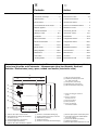
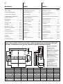

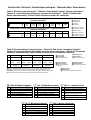
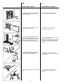
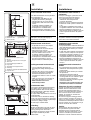


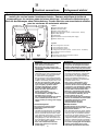

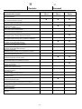
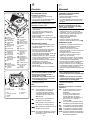

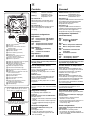
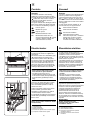
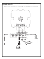
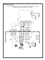
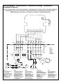
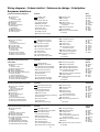
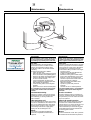


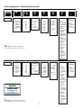


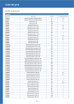

![MM12822 RvL 5-02 [German] Handheld](http://vs1.manualzilla.com/store/data/006788843_1-dd202c6a8f9102ffe4081d3aeba5a900-150x150.png)