1
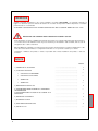
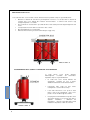
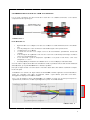
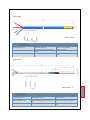
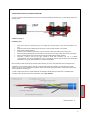
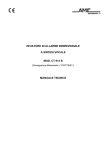
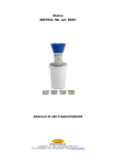
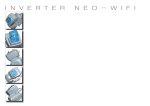
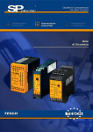
NOTE INSTALLAZIONE SCS/SONDE Pt100 1MN0118 REV. 0 opera con sistema qualità certificato ISO9001:2008 TECSYSTEM S.r.l. 20094 Corsico (MI) Tel.: +39-024581861 Fax: +39-0248600783 http://www.tecsystem.it R. 1.0 28/05/15 ITALIANO PREMESSA Vogliamo innanzitutto ringraziarvi per aver scelto di utilizzare un prodotto TECSYSTEM, e vi suggeriamo vivamente di leggere con attenzione il presente manuale di istruzioni: Vi consentirà di comprendere l’utilizzo del prodotto e di sfruttare pienamente tutte le sue funzionalità. ATTENZIONE ! QUESTO MANUALE E’ VALIDO E COMPLETO PER I BOX SCS/SONDE MODELLO: PTSE – PTFE. REGOLE PER UNA CORRETTA INSTALLAZIONE DELLE SONDE E SCS BOX Al fine di garantire un corretto e affidabile funzionamento del sistema per il controllo della temperatura del trasformatore, è necessario attenersi alle indicazioni fornite in questo documento per l’installazione: della centralina, delle cassette di collegamento SCS e delle sonde Pt100. Ogni SCS BOX viene realizzata su specifica richiesta del costruttore del trasformatore; in relazione all’applicazione e alle norme di sicurezza del trasformatore, le configurazioni delle SCS e le sue specifiche costruttive posso variare. L’installatore / utilizzatore del prodotto è ritenuto responsabile della corretta installazione del prodotto e della sua sicurezza. INDICE PAGINA 2 1) NORME PER LA SICUREZZA ………....................................... 3 2) SPECIFICHE TECNICHE ………………………………….. 4 • CASSETTA SCS POLIAMMIDE ………………………………….. — • CASSETTA SCS ALLUMINIO ………………………………….. — • SONDE PTSE ………………………………….. 5 • SONDE PTFE ………………………………….. — 3) MONTAGGIO CASSETTA SCS ………………………………….. 6 4) POSIZIONAMENTO DELLE SONDE ALL’ INTERNO DEL TRASFORMATORE ………………………………….. — 5) COLLEGAMENTO DELLE CASSETTA SCS /SONDE ALLA CENTRALINA ………………………………….. 7 6) NORME PER LA GARANZIA ………………………………….. 8 7) DIAGNOSTICA GUASTI ………………………………….. — 8) SMALTIMENTO APPARECCHIO ………………………………….. 9 9) CONTATTI UTILI ………………………………….. — NORME PER LA SICUREZZA ATTENZIONE: Leggere attentamente il manuale prima di iniziare ad effettuare l’installazione o la verifica funzionale della cassetta SCS o delle sonde. Conservare le istruzioni per una futura consultazione. Non avvicinarsi o toccare il cablaggio della cassetta SCS e delle sonde se il trasformatore è in funzione. Ogni operazione su SCS o sonde deve essere eseguita con il trasformatore spento. Seguire sempre le norme di sicurezza indicate dal costruttore del trasformatore e o quelle dell’impianto su cui state intervenendo. Qualsiasi intervento sul prodotto deve essere affidato ad un tecnico riparatore qualificato. La mancata osservanza di queste precauzioni può provocare danni, incendi o scosse elettriche, con possibili lesioni gravi! LIQUIDI Non esporre l’apparecchiatura a gocce o schizzi di liquidi, non posizionare in luoghi con umidità oltre il 90% e non toccare mai con mani bagnate o umide durante i temporali. PULIZIA Prima di pulire la cassetta SCS disconnettere sempre il cavo di alimentazione della centralina, per spolverare utilizzare un panno asciutto, senza solventi o detergenti, e dell’aria compressa. OGGETTI Non inserire mai oggetti nella cassetta SCS. Se ciò accade scollegare la centralina e rivolgersi ad un tecnico. UTILIZZO RISERVATO A PERSONALE COMPETENTE Il bene acquistato è un congegno elettronico sofisticato per cui assolutamente non idoneo all’uso da parte di personale non qualificato. Qualsiasi intervento dovrà essere eseguito da un tecnico specializzato. ACCESSORI L’utilizzo di accessori o parti di ricambio non originali potrebbe causare danni alla centralina e mettere a rischio la sicurezza dell’utilizzatore. Nel caso di guasti contattare l’assistenza tecnica. LOCAZIONE Installare le sonde e SCS in luoghi protetti da schizzi d’acqua e raggi solari. Non posizionare vicino a fonti di calore superiori ai parametri indicati nel presente manuale. Posizionare su superfici stabili, lontano da vibrazioni. Posizionare la centralina più lontano possibile da eventuali campi magnetici di forte intensità. RIPARAZIONI Per eventuali guasti rivolgersi sempre a personale qualificato. INFO TECNICHE O SEGNALAZIONI Mail: [email protected] — tel: 02/4581861 3 SPECIFICHE TECNICHE CASSETTA SCS POLYAMIDE 1MN0120 REV. 0 CARATTERISTICHE CONTENITORE CARATTERISTICHE PASSA CAVI CARATTERISTICHE MORSETTIERA COLORE: RAL7001 DIMENSIONI: PG16 SEZIONE FILO 0,25 a 1,5mm² GRADO PROTEZIONE IP55 GRADO PROTEZIONE: IP54 RESISTENZA ALLA FIAMMA UL94V0 MATERIALE: POLYAMIDE UL 94V0 MATERIALE: POLYAMIDE UL 94V0 TEMPERATURA DI ESERCIZIO -20°C+120°C CASSETTA SCS ALLUMINIO 1MN0116 REV. 0 CARATTERISTICHE CONTENITORE 4 CARATTERISTICHE PASSA CAVI CARATTERISTICHE MORSETTIERA COLORE: RAL9006 DIMENSIONI: PG16-PG21 SEZIONE FILO 0,25 a 1,5mm² GRADO PROTEZIONE: IP66 GRADO PROTEZIONE: IP54 RESISTENZA ALLA FIAMMA UL94V0 MATERIALE: ALLUMINIO MATERIALE: OTTONE NICHELATO TEMPERATURA DI ESERCIZIO -20°C+120°C SONDA PTSE 1MN0115 REV. 0 CARATTERISTICHE SONDA PTSE DIMENSIONE STANDARD 2,5mt TEMPERATURA MAX: 200°C SEZIONE CAVO Ø 5,2 SCHEMATO SONDA Pt100 OHM 0°C CL.B PROVA DI RIGIDITA’ DIELETTRICA 5KVac TRA CONDUTTORI IN CORTO E GUAINA. COLLEGAMENTO 3 FILI (BIANCO –ROSSO-ROSSO) MATERIALE: GOMMA SILICONICA SEZIONE CONDUTTORI: 3X0,35mmq twistati IDENTIFICAZIONE LOTTO/ANNO DI PRODUZIONE SONDA PTFE 1MN0119 REV. 0 CARATTERISTICHE SONDA PTFE DIMENSIONE STANDARD 2,5mt TEMPERATURA MAX: 220°C SEZIONE CAVO Ø 5,5 SONDA Pt100 OHM 0°C CL.B PROVA DI RIGIDITA’ DIELETTRICA 30KVac TRA CONDUTTORI IN CORTO E PUNTALE PTFE. COLLEGAMENTO 3 FILI (BIANCO –TRASPARENTE –TRASPARENTE ) MATERIALE: TEFLON SEZIONE CONDUTTORI: 3X0,38mmq twistati IDENTIFICAZIONE LOTTO/ANNO DI PRODUZIONE 5 MONTAGGIO CASSETTA SCS La cassetta SCS deve essere montata su un lato del trasformatore rispettando sempre le seguenti indicazioni: • • • • • Mantenere la distanza di sicurezza tra gli avvolgimenti in tensione e la cassetta SCS. La distanza di sicurezza deve essere indicata dal costruttore del trasformatore in funzione delle tensione sugli avvolgimenti primario e secondario. Non posizionare la cassetta SCS in prossimità del flusso d’aria calda proveniente dagli avvolgimenti o dal nucleo. La temperatura di esercizio della cassetta va da -20°C a 120°C. Massima umidità 90% (non condensante) Ambiente di lavoro interno (protetto da schizzi d’acqua e raggi solari) 1MN0117 REV. 0 POSIZIONAMENTO DELLE SONDE ALL’ INTERNO DEL TRASFORMATORE Le sonde devono essere inserite all’interno dell’avvolgimento secondario del trasformatore rispettando sempre le seguenti indicazioni: 1MN0117 REV. 0 6 • La sonda deve essere inserita all’interno del avvolgimento secondario per circa il 30-40% dell’altezza totale della colonna del trasformatore. • L’inserimento della sonda non deve restringimenti o occlusioni di nessun tipo. • Il cavo delle Pt100 deve essere posato in modo lineare, senza creare avvolgimenti e deve essere protetto e fissato mediante apposita canalina. • La tipologia di sonda installata deve rispetta le nome di sicurezza previste per le tensioni sulla quale è applicata. L’installatore / utilizzatore del trasformatore è ritenuto responsabile della corretta installazione del prodotto e della sua sicurezza. trovare COLLEG GAMENTO DEL LLA CASSETT TA SCS /SONDE E ALLA CENTRALINA Per un corretto collegamento dei se ensori Pt100 tra a la scatola SCS e la centra alina termometrica, occorre attenersi a osamente alle seguenti regole: scrupolo 1MN0 0117 REV. 0 d e: Norme d’installazione • • • • • • • Ogni Pt100 deve d essere colllegata con un ca avo a tre condu uttori con sezion ne minima di 0,3 35 mm² e massiima di 1 mm². ere schermato con c calza di ram me stagnato con n ricopertura all’’ 80% Il cavo di prollunga deve esse I conduttori devono essere tw wistati. azione, preferib bilmente dal la ato della Lo schermo del cavo deve essere collegato a terra solo da una termina centralina. nali delle sonde non deve esse ere vicino a cavvi di trasporto d di energia, sia di d bassa Il cavo di trassporto dei segn tensione che di media/alta te ensione. Il cavo delle e Pt100 e quello di trasporto o dei segnali deve d essere po osati in modo lineare, senza creare avvolgimenti su se stesso. ntalini per l’intesstazione dei con nduttori devono essere ben crim mpati per evitare e falsicontatti. Eventuali pun c si attiene scru upolosamente alle a norme d’installazione fornitte, si potrebbero o verificare delle e anomalie nella a lettura Se non ci della tem mperatura, per le quali TECSYS STEM non è chiamata a rispon ndere. er un migliore contatto c con la a morsettiera a molla della sca atola SCS-S, non n utilizzare i tterminalini a crrimpare. Nota: pe Inserire i fili spelati. Un’insta allazione non conforme c alle re egole indicate da TECSYSTE EM, nell’ambito applicativo dei trasformatori/m motori elettrici,, può comporttare: errate lettture di tempe eratura, allarmii o sganci an nomali, guasti delle sonde Pt100, P danneggiamento degli ingressi Pt100 delle d centralina. Con lo scopo di suppo ortare il cliente, TECSYSTEM M S.r.l. ha realiz zzato un proprio o cavo speciale e per il trasporrto dei utti i requisiti di protezione p previsti : mod. CTES S 1CA0003. segnali di misura, a norrme CEI, con tu 1M MN0034 REV V. 0 7 SPECI FI CH E TECN I CH E D EL CAVO D I ESTEN SI ON E PER Pt 1 0 0 1. Cavo 20 x AWG 20/19 Cu/Sn 2. Sezione 0,55 mm² 3. Isolamento antifiamma PVC 4. Norme CEI 20.35 5. Massima temperatura di esercizio : 90°C 6. Conformazione : 4 terne di tre conduttori twistati e colorati 7. Schermo in Cu/Sn 9. Diametro esterno 12 mm. 10. Fornitura standard in matasse da 100m AVVISO IMPORTANTE Prima di effettuare la prova di isolamento del quadro elettrico, su cui è installata la centralina, si deve staccare la stessa dalla linea di alimentazione e scollegare le sonde, onde evitare che venga seriamente danneggiata. NORME PER LA GARANZIA Il Prodotto acquistato è coperto da garanzia del produttore o del venditore nei termini ed alle condizioni indicati nelle “Condizioni Generali di Vendita Tecsystem s.r.l.”, consultabili sul sito www.tecsystem.it e/o al contratto di acquisto stipulato. La Garanzia viene riconosciuta solo quando il Prodotto si dovesse guastare per cause imputabili alla TECSYSTEM srl, quali difetti di produzione o di componenti utilizzati. La Garanzia non è valida quando il Prodotto risultasse manomesso/modificato, erroneamente connesso, causa tensioni di alimentazione fuori dei limiti consentiti, non rispetto dei dati tecnici d’impiego e montaggio, come descritto in questo manuale di istruzione. La Garanzia è sempre intesa f.co ns. sede di Corsico come stabilito dalle “Condizioni Generali di Vendita”. DIAGNOSTICA GUASTI CAUSE E RIMEDI Una delle sonde risulta essere interrotta Verificare che: i fili di collegamento siano ben serrati, mediante l’ausilio di un multimetro verificare la continuità dei conduttori. Una delle sonde risulta essere in corto Mediante l’ausilio di un multimetro misurate il valore di resistenza della sonda tra il conduttore bianco e i due rossi (trasparenti) Durante l’utilizzo delle sonde avete riscontrato Controllare i collegamenti delle sonde Pt100, verificare le indicazioni riportate nei paragrafi: collegamento della cassetta dell’ errate letture SCS/Sonde alla centralina pag. 7 8 SMA ALTIMEN NTO APPA ARECCH HIO Le diretttive europee 20 012/19/CE (RA AEE) e 2011/65//CE (RoHS) so ono state approvvate per ridurre e i rifiuti di appa arecchi elettrici ed elettronici e incentivare il ricciclaggio e il riutilizzo dei materiali e dei componenti di tali apparecchi, riduce endo in m lo smaltim mento dei residu ui e dei compossti nocivi provenienti da materia ale elettrico ed e elettronico. questo modo Tutti gli appare ecchi elettrici ed elettronici forrniti a partire da al 13 agosto 20 005 sono contrrassegnati con questo simbolo, ai sensi della direttiiva europea 20 002/96/CEE sui rifiuti di apparrecchiature eletttriche ed elettrroniche (RAEE). Qualssiasi apparecchio elettrico o ele ettronico contra assegnato con questo q marchio o deve essere smaltito s separatamente e rispetto ai norm mali rifiuti dome estici. Restituzzione apparecchi elettrici usati: contattare TE ECSYSTEM o l’agente TECSY YSTEM per rice evere informazioni sul corretto o smaltimento de egli apparecchi.. TECSYSTEM è consap pevole dell’impa atto dei propri prodotti p sull’amb biente e chiede ai propri clienti un supporto atttivo per lo smalttimento corretto o ed ecocompatiibile delle apparrecchiature. CO ONTATTI UTILI FO TECNICH HE : [email protected] INF INF FO COMMER RCIALI : info@ @tecsystem.itt 9 INSTALLATION RULES for SCS/SENSOR Pt100 1MN0118 REV. 0 operates under certified quality system ISO9001: 2008 TECSYSTEM S.r.l. 20094 Corsico (MI) Tel.: +39-024581861 Fax: +39-0248600783 http://www.tecsystem.it R. 1.0 28/05/15 ENGLISH “Translations of the original instructions” INTRODUCTION First of all we wish to thank you for choosing to use a TECSYSTEM product and recommend you read this instruction manual carefully: You will understand the use of the equipment and therefore be able to take advantage of all its functions. ATTENTION! THIS MANUAL IS VALID AND COMPLETE FOR BOX SCS / SENSORS MODEL: PTSE - PTFE. RULES FOR PROPER INSTALLATION OF SENSORS AND SCS BOX In order to ensure safe and reliable operation of the system to control the temperature of the transformer, you must follow the instructions provided in this document for installation and connection SCS BOX and Pt100 to the monitoring unit. Each SCS BOX is made on specific request of the manufacturer of the transformer; in relation to the application and the safety standards of the transformer, the configurations of the SCS and its construction specifications can vary. The installer / user of the product is responsible for the proper installation of the product and its safety. CONTENTS PAG. 2 1) SAFETY REGULATIONS ………....................................... 3 2) TECHNICAL SPECIFICATIONS ………………………………….. 4 BOX SCS POLYAMMIDE ………………………………….. — BOX SCS ALUMINIUM ………………………………….. — PTSE SENSOR ………………………………….. 5 PTFE SENSOR ………………………………….. — 3) MOUNTING SCS BOX ………………………………….. 6 4) POSITIONING OF SENSORS INSIDE THE TRANSFORMER ………………………………….. — 5) CONNECTING BOX SCS / SENSORS TO UNIT ………………………………….. 7 6) WARRANTY REGULATIONS ………………………………….. 8 7) TROUBLESHOOTING ………………………………….. — 8) EQUIPMENT DISPOSAL ………………………………….. 9 9) USEFUL CONTACTS ………………………………….. — SAFETY REQUIREMENTS ATTENTION Carefully read the manual before you start installation or functional testing of the cassette SCS or the probes. Keep the instructions for future reference. Do not approach or touch the wiring box SCS and probes if the transformer is in operation. Each operation of SCS or probes must be performed with the transformer off. Always follow the safety indications given by the manufacturer of the transformer and or the system on which you are working. All the operations on the product must be performed by a qualified technician only. Failure to follow these instructions can result in damage, fire or electric shock, with possible serious injury! LIQUIDS Do not expose the equipment to dripping or splashing liquids, do not place in places where humidity is over 90% and never touch with wet hands during thunderstorms. CLEANING Before cleaning the BOX SCS always disconnect the power cord of the unit, use a dry cloth to dust, no solvents or detergents, and compressed air. OBJECTS Never insert objects into the BOX SCS. If this happens, unplug the unit and call a technician. USE RESERVED TO QUALIFIED PERSONNEL The purchased goods are a sophisticated electronic device that is totally unsuitable to be used by nonqualified personnel. Any intervention must be carried out by a specialist engineer. ACCESSORIES The use of accessories or spare parts not original may damage the unit and endanger the safety of the user. In case of failure contact technical support. POSITIONING Install the probes and SCS in places protected from splashes of water and sunlight. Do not place near heat sources exceeding the parameters specified in this manual. Place on a stable surface, away from vibration. Place the unit as far away from any strong magnetic fields. MAINTANANCE If any faults occur always contact qualified personnel. TECHNICAL INFORMATION Mail: [email protected] — tel: 02/4581861 3 TECHNICAL SPECIFICATIONS SCS BOX POLYAMIDE 1MN0120 REV. 0 BOX SPECS CABLE GLAND SPECS TERMINAL SPECS COLOUR: RAL7001 DIMENSION: PG16 SECTION WIRE 0,25 a 1,5mm² PROTECTION RATE IP55 PROTECTION RATE : IP54 FLAME RESISTANCE UL94V0 MATERIAL: POLYAMIDE UL 94V0 MATERIAL: POLYAMIDE UL 94V0 TEMPERATURA DI ESERCIZIO -20°C+120°C SCS BOX ALUMINIUM 1MN0116 REV. 0 BOX SPECS 4 CABLE GLAND SPECS TERMINAL SPECS COLOUR: RAL9006 DIMENSION: PG16-PG21 SECTION WIRE 0,25 to 1,5mm² PROTECTION RATE: IP66 PROTECTION RATE: IP54 FLAME RESISTANCE UL94V0 MATERIAL: ALUMINIUM MATERIAL: BRASS NICKEL WORKING TEMPERATURE: -20°C+120°C PTSE SENSOR 1MN0115 REV. 0 PTSE SENSOR SPECS STANDARD LENGHT 2,5mt TEMPERATURE MAX: 200°C WIRE SECTION Ø 5,2 SHIELDED SENSOR Pt100 OHM 0°C CL.B TEST OF DIELECTRIC STRENGHT AT 5KVac BETWEEN SHORT CIRCUIT CABLES AND JACKET. 3 WIRE CONNECTION (WHITE –RED-RED) MATERIAL: SILICON RUBBER WIRE SECTION: 3X0,35mmq twistati IDENTIFICATION BY LOT/PRODUCTION YEAR PTFE SENSOR E 1MN0119 REV. 0 PTFE SENSOR SPECS STANDARD LENGHT 2,5mt TEMPERATUR MAX: 220°C WIRE SECTION Ø 5,5 SENSOR Pt100 OHM 0°C CL.B TEST OF DIELECTRIC STRENGHT AT 30KVac BETWEEN SHORT CIRCUIT CABLES AND PTFE TIP. 3 WIRE CONNECTION (WHITE –TRANSPARENT –TRANSPARENT) MATERIAL: TEFLON WIRE SECTION: 3X0,38mmq twisted IDENTIFICATION BY LOT/PRODUCTION YEAR 5 MOUNTING SCS BOX The SCS box must be mounted on one side of the transformer respecting the following guidelines: Maintain a safe distance between the windings voltage and the SCS BOX. The safety distance must be specified by the manufacturer of the transformer according to the voltage on the primary and secondary windings. Do not place the SCS BOX near the hot air flow coming from the windings or the core. Working temperature range of the SCS BOX: -20°C a 120°C. Maximum humidity 90% (non-condensing) Location place protected from splashing water and sunlight. 1MN0117 REV. 0 POSITIONING OF SENSORS INSIDE THE TRANSFORMER Sensors should be inserted into the secondary of the transformer respecting the following guidelines: 1MN0117 REV. 0 6 The probe must be inserted inside the secondary winding for about 30-40% of the total height of the column of the transformer. Avoid from any occlusion into the channel where the sensor has to be placed. The cable of the Pt100 must be laid in a linear mode, without creating windings and must be protected and secured by a special duct. The sensor type installed must comply with the rules of the security measures for the tensions on which it is applied. The installer / user of the transformer is responsible for the proper installation of the product and its safety. CONNECTING SCS BOX TO THE MONITORING UNIT To ensure a safe connection between the Pt100 sensor and the temperature monitoring unit, you must strictly perform the following rules: 1MN0117 REV. 0 Installation rules: Every sensor must be connected using a 3 wire cable with minimum section of 0,35 mm² and maximum of 1 mm². Extension cable must be shielded with tinned copper covering at least the 80% of the surface. Wires has to be twisted together. Shield must be connected to ground from only one terminal, choosing the side of the monitoring unit. Cable transporting data signals from the sensors must not be close to energy cables either low or high voltage. Sensor and data cables must be positioned as linear as possible without creating windings. Terminals, if present, must be very tight crimped to avoid false connection. Se non ci si attiene scrupolosamente alle norme d’installazione fornite, si potrebbero verificare delle anomalie nella lettura della temperatura, per le quali TECSYSTEM non è chiamata a rispondere. Note: for better contact with the spring terminal of the SCS BOX, do not use crimp terminals. Insert the stripped wires. Installation not in accordance with the rules set by TECSYSTEM, within the application of the transformers / electric motors, can cause: incorrect temperature readings, alarms or abnormal tripping, RTD faults , damge to the Pt100 inputs of the temperature monitoring unit. In order to support the customer, TECSYSTEM Srl has realized a special cable for the transport of the data signals, according to CEI, with all the protection requirements: mod. CTES 1CA0003. 1MN0034 REV. 0 7 TECHNICAL SPECIFICATIONS OF THE EXTENSION CABLE FOR Pt100 1. 2. 3. 4. 5. 6. 7. 8. 9. 10. Cable 20 x AWG 20/19 Cu/Sn Section 0.55 mm² Flame retardant insulation PVC 105 CEI 20.35 IEC 332.1 regulations Maximum operating temperature: 90°C Conformation: 4 sets of three twisted and coloured conductors Shield in Cu/Sn Flame retardant PVC sheath External diameter 12mm Standard conformation in 100m coils IMPORTANTE NOTICE Before performing the insulation test of the control panel, where the unit is installed, you have to disconnect it from the power line and disconnect the probes, in order to avoid serious damage. WARRANTY REGULATIONS The purchased product is covered by manufacturer's or seller's warranty as per the "Tecsystem s.r.l.'s General Conditions of Sale" available at www.tecsystem.it and/or the purchase agreement drawn up. Said Warranty is valid only when the Product fails due to reasons attributable to TECSYSTEM srl, such as manufacturing faults or faulty components. The Warranty is invalid when the product is tampered with / modified, connected incorrectly, causing voltages outside the permitted limits, non-compliant with the use and installation technical specifications, as described in this instruction manual. TROUBLESHOOTING One sensor seems to be broken Check the wires are well tightened and, by a multimeter instrument, check the continuity. One of the sensor seems to be in short circuit. By a multimeter instrument check the resistance value of the sensor between the white wire and the two reds (transparent). Information from sensors seems to be wrong. 8 WHAT TO DO Check connections of the sensors, check if everythings is correct in respect of suggestions on page 7. EQUIPMENT DISPOSAL European directives 2012/19/EC (WEEE) and 2011/65/EC (RoHS) have been approved to reduce electrical and electronic waste and promote the recycling and reuse of the materials and components of this equipment, cutting down on the disposal of the residues and harmful components of electrical and electronic materials. All the electrical and electronic equipment supplied after 13 August 2005 is marked with this symbol, pursuant to the European directive 2002/96/EEC on electrical and electronic waste (WEEE). Any electrical or electronic equipment marked with this symbol must be disposed of separately from normal domestic waste. Returning used electrical devices: contact TECSYSTEM or the TECSYSTEM agent for information on the correct disposal of the devices. TECSYSTEM is aware of the impact its products have on the environment and asks its customers active support in the correct and environmentally-friendly disposal of its devices. USEFUL CONTACTS TECHNICAL: [email protected] SALES: [email protected] 9