1
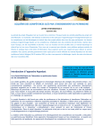
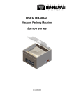
Euroline
Istruzioni
Istruzioni per l’uso
Istruzioni per l’uso
Per garantire la sicurezza del personale addetto al funzionamento e alla
manutenzione durante l’utilizzo dei macchinari FAS, è essenziale istruire
il personale su come utilizzare il presente manuale.
Il manuale si compone di tre parti:
Parte prima
Contiene istruzioni relative alla sicurezza e informazioni sulla
responsabilità.
Il personale addetto all’utilizzo di questa macchina è tenuto a leggere e a
comprendere questa parte.
Parte seconda
Contiene istruzioni su come utilizzare la macchina.
Questa parte deve essere a disposizione degli operatori.
Parte terza
Fornisce istruzioni relative a manutenzione, impostazioni e regolazioni.
Questa parte, disponibile solo in lingua inglese, è riservata al personale
addetto alla manutenzione e ai responsabili dei settori produttivo/
operativo.
La macchina viene consegnata unitamente a un manuale completo,
comprendente tutte le tre parti.
Per l’acquisto di manuali o parti supplementari, rivolgersi a:
FAS Converting Machinery AB / Service department
Telefono: +46 411 692 60.
Service telefono +46 411 69298
Fax: +46 411 127 40.
Email: [email protected].
giugno 2014
Euroline
ii
Istruzioni per l’uso
Indice
Istruzioni per l’uso
Parte prima
Istruzioni relative alla sicurezza e alla responsabilità
Istruzioni relative alla sicurezza e alla responsabilità
Responsabilità . . . . . . . . . . . . . . . . . . . . . . . . . . . . . . . . . . . . 2
Informazioni relative alla salute e alla sicurezza
Precauzioni di sicurezza
Sicurezza
Parte seconda
Manuale di istruzioni
Installazione
Interblocco . . . . . . . . . . . . . . . . . . . . . . . . . . . . . . . . . . . . . . . 8
Quadro operatore
Quadro indicatori . . . . . . . . . . . . . . . . . . . . . . . . . . . . . . . . . . 9
Utilizzo del quadro di comando. . . . . . . . . . . . . . . . . . . . . . 10
Menu del quadro di comando
Menu principale . . . . . . . . . . . . . . . . . . . . . . . . . . . . . . . . . . 11
Menu impostazioni SP (F1) . . . . . . . . . . . . . . . . . . . . . . . . . 12
Menu Tape (F4) . . . . . . . . . . . . . . . . . . . . . . . . . . . . . . . . . . 13
Menu impostazioni BM (F2) . . . . . . . . . . . . . . . . . . . . . . . . 14
Menu Tensione BM (F5) . . . . . . . . . . . . . . . . . . . . . . . . . . . 15
Struttura dei menu
Avviamento e funzionamento
Prima dell'avviamento . . . . . . . . . . . . . . . . . . . . . . . . . . . . . 17
Avviamento
Inserimento del nastro nell'unità SP . . . . . . . . . . . . . . . . . . 23
Spegnimento della macchina
Spegnimento programmato . . . . . . . . . . . . . . . . . . . . . . . . . 25
Spegnimento di emergenza . . . . . . . . . . . . . . . . . . . . . . . . . 25
Arresto automatico. . . . . . . . . . . . . . . . . . . . . . . . . . . . . . . . 25
Part Three
Settings and adjustment
Service
Settings and adjustment
Preheat settings for Off-line production . . . . . . . . . . . . . . .
CF-unit
Chain tension . . . . . . . . . . . . . . . . . . . . . . . . . . . . . . . . . . . .
Checking timing belt tension . . . . . . . . . . . . . . . . . . . . . . . .
Checking the variator belt . . . . . . . . . . . . . . . . . . . . . . . . . .
Changing knives . . . . . . . . . . . . . . . . . . . . . . . . . . . . . . . . .
Changing the seal wire. . . . . . . . . . . . . . . . . . . . . . . . . . . . .
Changing the brushes on the sealing bars . . . . . . . . . . . . . .
Servo motors . . . . . . . . . . . . . . . . . . . . . . . . . . . . . . . . . . . .
giugno 2014
Euroline
28
30
33
35
36
37
39
41
iii
Istruzioni per l’uso
Setting of grippers . . . . . . . . . . . . . . . . . . . . . . . . . . . . . . . .
Checking of belt tension, drive motor . . . . . . . . . . . . . . . . .
Setting of fingers in horizontal position . . . . . . . . . . . . . . .
Adjusting the high speed nip . . . . . . . . . . . . . . . . . . . . . . . .
Changing the nip bars from reverse to standard setting. . . .
Lubrication instructions
CF-unit . . . . . . . . . . . . . . . . . . . . . . . . . . . . . . . . . . . . . . . . .
Lubricants . . . . . . . . . . . . . . . . . . . . . . . . . . . . . . . . . . . . . .
SP-unit . . . . . . . . . . . . . . . . . . . . . . . . . . . . . . . . . . . . . . . . .
Alarm list
Fault tracing
SP-unit . . . . . . . . . . . . . . . . . . . . . . . . . . . . . . . . . . . . . . . . .
giugno 2014
Euroline
42
43
43
43
44
45
45
46
49
iv
Euroline
Parte prima
Istruzioni relative alla
sicurezza e alla
responsabilità
Marzo 2007
Istruzioni relative alla sicurezza e alla responsabilità
Istruzioni relative alla sicurezza e alla responsabilità
Responsabilità
La Eurolineè stata progettata per la perforazione, sigillatura e
avvolgimento di sacchetti di plastica in rotolo di pellicola in polietilene. È
vietato qualsiasi altro impiego che preveda l’avvolgimento di altri
materiali, salvo previa autorizzazione di FAS Converting Machinery AB.
FAS Converting Machinery AB non potrà essere ritenuta responsabile per
danni o infortuni provocati da modifiche apportate al macchinario.
FAS Converting Machinery AB non potrà essere ritenuta responsabile
qualora la macchina venga modificata o utilizzata in modo diverso da
quanto previsto nelle istruzioni o specifiche del produttore.
FAS Converting Machinery AB non si assume alcuna responsabilità in
caso di mancata consegna dei manuali al personale incaricato.
Tutte le macchine di FAS Converting Machinery AB sono corredate da
manuali di istruzioni. È responsabilità dei clienti accertarsi che il
personale abbia libero accesso al presente manuale. È responsabilità dei
clienti istruire adeguatamente gli operatori sul funzionamento e sulla
manutenzione del macchinario FAS in condizioni di sicurezza, evitando
in questo modo qualsiasi incidente.
giugno 2014
Euroline
2
Informazioni relative alla salute e alla sicurezza
Informazioni relative alla salute e alla sicurezza
Il presente documento contiene importanti informazioni sui pericoli. Tali
informazioni sono rappresentate dalle indicazioni di Pericolo, Avvertenza
e Attenzione, contenute nel presente capitolo. La comparsa di un simbolo
di avvertenza in qualsiasi punto del presente manuale significa che, prima
di procedere, è necessario consultare l’apposita indicazione di Pericolo o
Avvertenza all’interno del presente capitolo. Il simbolo di Avvertenza è il
seguente:
!
Prima di mettere in funzione la macchina, leggere attentamente il presente
capitolo e prestare particolare attenzione alle indicazioni di Pericolo,
Avvertenza e Attenzione. Il mancato rispetto di queste indicazioni, può
causare gravi infortuni al personale o danni all’attrezzatura.
Il personale incaricato del funzionamento e della manutenzione della
macchina dovrà essere adeguatamente addestrato sul funzionamento della
macchina e prendere dimestichezza con le modalità di funzionamento.
!
!
Pericolo
Pericolo immediato per la vita!
La mancata osservanza di questa informazione metterà in
pericolo la vostra vita! Ogni INDICAZIONE DI PERICOLO
stabilisce nello specifico la natura di un determinato pericolo e il
modo in cui questo può essere evitato. Le INDICAZIONI DI
PERICOLO sono riportate nello stesso stile di questa
indicazione.
Avvertenza Rischio di gravi infortuni!
La mancata osservanza di questa informazione potrebbe
provocare gravi lesioni al personale! Ogni INDICAZIONE DI
AVVERTENZA stabilisce nello specifico la natura di un
determinato pericolo e il modo in cui questo può essere evitato.
Le INDICAZIONI DI AVVERTENZA sono riportate nello stesso
stile di questa indicazione.
Cautela
giugno 2014
Rischio di lesioni di minore entità o danno all’attrezzatura!
La mancata osservanza di questa informazione può provocare
lesioni di minore entità o danni all’attrezzatura! Ogni indicazione
di Attenzione stabilisce nello specifico la natura di un determinato
pericolo e il modo in cui questo può essere evitato. Le indicazioni
di Attenzione sono riportate nello stesso stile di questa
indicazione.
Euroline
3
Precauzioni di sicurezza
Precauzioni di sicurezza
!
Pericolo
Questa macchina è alimentata da corrente elettrica di rete e
pertanto, quando è accesa, al suo interno sono presenti tensioni
letali. Il personale deve procedere con la massima cautela
quando opera in prossimità della macchina e i coperchi, i pannelli
o i ripari sono smontati.
!
Avvertenza La macchina contiene parti in movimento e presenta dunque un
rischio di lesioni quando i ripari fissi della macchina sono
smontati. Le regolazioni sulla macchina vanno eseguite
esclusivamente da personale autorizzato, che deve procedere
sempre con estrema cautela.
!
Avvertenza Il personale che opera in prossimità della macchina deve
prestare particolare attenzione a indumenti, guanti e capelli
lunghi. Tutti gli operatori con i capelli lunghi dovranno sempre
indossare una retina per capelli. Gli operatori non devono
indossare guanti o abiti ampi.
Cautela
Durante la manipolazione della pellicola in plastica può prodursi
elettricità statica.
Particolari avvertenze per l'unità CF
!
Avvertenza Le lame dell'unità CF sono affilate. Per evitare il rischio di
infortuni, il personale deve procedere con la massima cautela
quando maneggia le lame della perforatrice.
!
Avvertenza Il ballerino si sta muovendo in verticale. Per evitare il rischio di
infortuni, tenere sempre lontane le mani dal ballerino mentre
questo è in movimento.
giugno 2014
Euroline
4
Precauzioni di sicurezza
Particolari avvertenze per l'unità SP
!
Avvertenza Il ballerino si sta muovendo in verticale. Per evitare il rischio di
infortuni, tenere sempre lontane le mani dal ballerino mentre
questo è in movimento.
!
Avvertenza La macchina si fermerà in posizione di stand-by se la macchina
per sacchetti viene arrestata. La Euroline comincerà
automaticamente a ruotare non appena l'unità CF inizia a
funzionare. Vi è rischio di lesioni dovute agli alberi in movimento.
!
Avvertenza Il ballerino si sta muovendo in verticale. Tenere sempre lontane
le mani dal ballerino mentre questo è in movimento. Quando la
pellicola avanza nella macchina, assicurarsi che il ballerino sia in
posizione sollevata. Se il nastro frena, il ballerino si abbasserà
ad alta velocità. Vi è rischio di lesioni dovute a schiacciamento.
!
Avvertenza Durante il cambio rotolo, i perni di presa fuoriescono e ruotano
ad alta velocità. Vi è rischio di lesioni del personale dovute a
schiacciamento.
!
Avvertenza Nell’area della testina di scintillamento è presente alta tensione.
Tenere sempre lontane le mani da quest’area quando la scintilla
è impostata su "ON".
giugno 2014
Euroline
5
Sicurezza
Sicurezza
Per garantire la sicurezza dell’operatore, la macchina è dotata sia di ripari
fissi che di ripari apribili. La macchina è dotata di due pulsanti di arresto
di emergenza, la cui posizione è illustrata nella figura seguente.
5
6
1
Avvertenza, alta tensione
2
Avvertenza, alberi rotanti
3
Marchio CE
4
Arresto di emergenza
5
Avvertenza, schiacciamento
6
Avvertenza, barre di sigillatura calde
7
Interruttore di sicurezza
4
4
4
5
3
7
2
4
1
7
7
7
Fig. 1 Etichette e interruttori di sicurezza
Quando più macchine vengono collegate in linea, l’azionamento del
pulsante di arresto di emergenza, o l’apertura di un qualsiasi riparo o di
una qualsiasi macchina collegata in serie, provocherà l’arresto completo
di tutte le macchine della linea. Vedere “Spegnimento di emergenza” a
pagina 25, per il collegamento.
I ripari fissi non devono in nessun caso essere rimossi dalla macchina
durante la fase di produzione.
Gli interruttori di sicurezza non devono essere manomessi allo scopo di
bypassare i dispositivi di interblocco di sicurezza, rendendo così possibile
l’apertura dei ripari mentre la macchina è in produzione.
Qualsiasi interruttore di sicurezza rotto o guasto va immediatamente
sostituito.
giugno 2014
Euroline
6
Euroline
Parte seconda
Manuale di istruzioni
Febbraio 2011
Installazione
Installazione
La posizione della Euroline rispetto alle altre macchine della linea di
produzione è riportata nella Fig. 1.
Unità SP
Estrusore
oppure
Svolgitore
Unità CF
Fig. 1 Installazione tipica
La Euroline non va fissata in alcun modo, ma deve essere posizionata
direttamente sul pavimento, dove può essere spostata e dove è facilmente
accessibile per la manutenzione.
Connessioni elettriche e raccordi per l’alimentazione di aria compressa
sono presenti sulla parte inferiore della macchina. Per facilitare la
manutenzione, i cavi elettrici e i tubi dell’aria possono essere sospesi dal
soffitto e fissati per mezzo di connettori a sgancio rapido.
Connessione elettrica, standard:
400 V, 50 Hz, trifase, neutro e massa.
Portata fusibili:
16 A
Pressione necessaria aria compressa:6 bar
Consumo d’aria:
18 litri per cambio rotolo
Interblocco
La macchina può essere interbloccata, per garantire l’arresto automatico
di tutte le macchine della linea di produzione in caso di guasto a una
qualsiasi delle macchine stesse. Il cavo di interblocco è fornito con la
macchina. Se non si utilizza il sistema d’interblocco, occorre inserire
nell’interblocco uno speciale connettore che consente il funzionamento
della macchina. Vedere “Arresto automatico” a pagina 25 per
l’interconnessione delle macchine.
giugno 2014
Euroline
8
Quadro operatore
Quadro operatore
EUROLINE
1
Quadro di comando
2
Indicatore di potenza della scintilla
3
Manopola di regolazione della potenza
della scintilla
4
Selettore di modalità
Posizione sinistra
Accumulatore in alto, scintilla disattiva
Posizione centrale
Accumulatore in basso, scintilla disattiva
Posizione destra
Accumulatore in basso, scintilla attiva
5
Potenziometro di velocità macchina
6
Pulsante di avviamento macchina
(utilizzato anche per il cambio rotolo
manuale).
7
1
F1
F2
F3
F4
F5
F6
2
6
4
Pulsante di arresto macchina
(utilizzato anche la ritrazione dei perni di
presa).
3
5
7
Fig. 2 Quadro operatore
Quadro indicatori
1
Accumulatore riduzione velocità regolazione verso l'alto
2
Accumulatore riduzione velocità regolazione verso il basso
1
2
Fig. 3 Quadro indicatori
giugno 2014
Euroline
9
Quadro operatore
Utilizzo del quadro di comando
Il quadro di comando dispone di un display
incorporato che visualizza cinque videate
diverse: il Menu principale e quattro sottomenu.
È possibile visualizzare ciascuna videata
premendo il tasto funzione corrispondente, cioè
Menu principale o F1-F4. Le diverse videate
presentano i parametri letti da o immessi nel
sistema PLC della Euroline.
Alcuni parametri possono essere facilmente
modificati procedendo nel modo seguente:
1
Premere il tasto funzione corrispondente
(Menu principale o F1-F4).
2
Usare i quattro tasti freccia (rossi) per
passare al parametro da modificare. In
alcuni menu, occorre utilizzare i tasti
freccia giù (o su) per visualizzare tutte le
righe.
3
Fig. 4 Quadro di comando
Immettere il nuovo valore usando i tasti
numerici, quindi premere Invio (tasto con
anello rosso). Se il parametro è di tipo a
selezione alternativa (ad es. On/Off),
utilizzare il tasto Invio per passare da
un’alternativa all’altra.
giugno 2014
Euroline
10
Menu del quadro di comando
Menu del quadro di comando
Menu principale
Selezionare Menu principale premendo il
rispettivo pulsante (1)
Il menu principale viene visualizzato anche dopo
circa 30 secondi nel caso in cui non venga premuto
nessun altro tasto.
Bags (Sacchetti)
Imposta il numero di sacchetti da produrre per un
rotolo.
Cnt (Conteggio)
Mostra il numero di sacchetti nel rotolo che si sta
formando. Il cambio rotolo avviene quando il
numero del contatore corrisponde a quello
preimpostato ("Bags" [Sacchetti]).
SealsetSeal1
Mostra la percentuale di uscita di corrente max di
sigillatura
Seal1
Mostra la corrente attuale nel filo di sigillatura in
sealbar #1, che ha un filo con sezione di 1,65 mm
Fig. 5 Pulsante del menu principale
Bags 12
Cnt 06
Sealset
Seal1 4.0A
42%
Seal2 4.0A
Speed 50 m/min
Fig. 6 Menu principale
Seal2
Mostra la corrente attuale nel filo di sigillatura in
sealbar #2, che ha un filo con sezione di 5 mm.
La potenza di sigillatura può essere modificata
inserendo un valore diverso nel campo percentuale
"Sealset". Utilizzare i tasti freccia per selezionare
il campo e inserire un nuovo valore usando il
tastierino numerico.
Speed (Velocità)
Visualizza la velocità attuale della macchina. Per
modificare la velocità, con la macchina in
funzionamento fuori linea, ruotare il
potenziometro della velocità sul quadro operatore.
Se in modalità in linea, il potenziometro deve
essere sulla posizione massima.
giugno 2014
Euroline
11
Menu del quadro di comando
Menu impostazioni SP (F1)
Perf Pos set#
(Pos. di perf. imp. nr.)
Per l’impostazione manuale della posizione della
perforazione. Per potere eseguire l’impostazione
manuale, "set" (vedere "Submenu Auto perf set", di
seguito) deve essere impostato su OFF.
set# (imp. nr.)
Regola automaticamente la posizione della
perforzazione. Effettuare la selezione usando i tasti
freccia, quindi premere Invio per selezionare
Submenu Auto perf set sottostante.
Perf Pos 875
set#
Tearoff Speed 3
Tearoff
10 laps
Open-grippers 2 laps
Stop-ofline on
Direction CCW
Fig. 7 Menu F1, Menu impostazioni SP
Tearoff Speed
(Velocità strappo)
Imposta la velocità dei perni di presa durante la fase
di strappo. Sono preimpostate tre velocità: 1-bassa,
2-media e 3-alta.
Tearoff - laps
(Strappo - sovrapposizioni)
Impostare il numero di sovrapposizioni alla velocità
di strappo durante la fase di strappo.
Open-grippers
2
laps
(Apertura
pinze
2
sovrapposizioni)
Impostare il numero di sovrapposizione dei perni di
presa prima dell'apertura delle pinze dopo il cambio
rotolo.
Stop-ofline
(Arresto - fuori linea)
Se impostato su "on", l'intera linea si arresterà
quando si verifica un errore; se impostato su "off" si
arresterà solo l'unità SP quando si verifica un errore
nell'unità stessa.
Auto set perf
Direction #-(Direzione #--)
Senso di rotazione dei perni di presa, orario o
antiorario.
0
- 15
off
m/min
#---
15
- 30
m/min
#---
30
- 50
m/min
#---
Submenu Auto perf set
50
- 70
m/min
#---
Auto set perf
(Imp. autom perf.)
Contiene i valori preimpostati di Perf. Position
(Posizione perforazione). Utilizzato dalla macchina
quando l'opzione Auto set perf. è abilitata.
70
- 90
m/min
#---
giugno 2014
Euroline
90 -
m/min
#---
Fig. 8 Sottomenu F1, Menu Contatore,
"Auto perf set"
12
Menu del quadro di comando
Menu Tape (F4)
Tape (Nastro)
Impostare su ON per attivare la nastratrice, in
caso contrario impostare su OFF.
Start Tape - Bags
(Avvio nastro - Sacchetti)
Segnale di avvio per il nastro prodotto dopo un
numero preimpostato di sacchetti prima del
cambio rotolo.
Tape
500
Start Tape 2 Bags
Start Tape 0 pls
Fig. 9 Menu F4, Menu Tape
Start Tape -- pls
(Avvio nastro -- impulsi)
Il nastro viene alimentato per il numero di
impulsi impostato dopo l'emissione del segnale
di avvio. Questa caratteristica è usata per la
regolazione fine della lavorazione del nastro.
giugno 2014
Euroline
13
Menu del quadro di comando
Menu impostazioni BM (F2)
Servo (Servosistema)
Attiva / disattiva (ON/OFF) la funzione di perforazione e Servo ON
sigillatura (movimento), ad esempio disattiva tutti i
Length 600 mm
servosistemi.
Skirt 20
Length - mm (Lunghezza - mm)
Imposta la lunghezza desiderata del sacchetto, ovvero la Knife Servo ON
distanza fra due perforazioni.
Seal Servo
ON
Skirt (Orlo)
Imposta la lunghezza dell’orlo, cioè la distanza fra la
sigillatura e la perforazione. Il valore mostrato è fittizio.
Tuttavia una modifica ad esempio di 10 unità di questo
valore determina uno spostamento di 10 millimetri nella
posizione di sigillatura.
Auto Seal
ON
Min Seal Speed 30
Seal Alarm 1
3.8A
Seal Alarm 2
3.8A
Fig. 10 Menu F2 Impostazioni CF
Knife Servo
(Servosistema lame)
Attiva/disattiva (ON/OFF) il servosistema delle lame, ad
esempio la perforazione è disabilitata se il servosistema
delle lame è disattivato.
Seal Servo
(Servosistema sigillatura)
Attiva/disattiva (ON/OFF) il servosistema della sigillatura,
ad esempio la perforazione è disabilitata se il servosistema
della sigillatura è disattivato.
Auto Seal
(Sigillatura automatica)
Se impostato su ON, è necessaria una velocità minima della
macchina per attivare la potenza di sigillatura.
Min Seal Speed
(Velocità di sigillatura min.)
Se è attivata l'opzione "Auto Seal", il valore su questa linea
imposta la velocità minima che rende possibile la sigillatura.
Se la velocità scende al di sotto del valore impostato, la
sigillatura viene interrotta per evitare rotture del nastro
Seal Alarm 1
(Allarme 2 Sigillatura)
Imposta il livello di corrente minima di sigillatura, prima
che scatti l’allarme. Il livello va impostato a circa l’80%
della corrente assorbita per la sigillatura del sacchetto.
Seal Alarm 2
(Allarme 2 Sigillatura)
Imposta il livello di corrente minima di sigillatura, prima
che scatti l’allarme. Il livello va impostato a circa l’80%
della corrente assorbita per la sigillatura del sacchetto.
giugno 2014
Euroline
14
Menu del quadro di comando
Menu Tensione BM (F5)
Scale Factor #---(Fattore di scala #----)
Impostato dal costruttore su 2,525 - NON
modificare.
+ Tension -
Scale Factor 2.525
+ Tension
-
Fig. 11 Menu F5, Tensione CF
(+ Tensione -)
Utilizzare F2 e F4 per aumentare o ridurre la
tensione del nastro.
giugno 2014
Euroline
15
Struttura dei menu
Struttura dei menu
Menu
principale
Bags 12
Cnt 06
Sealset
Seal1 4.0A
42%
Seal2 4.0A
Speed 50 m/min
Settings
(Impostazioni)
Tape
500
Start Tape 2 Bags
Start Tape 0 pls
giugno 2014
SP
SP
Perf Pos 875
set#
Tearoff Speed 3
Tearoff
10 laps
Open-grippers 2 laps
Stop-ofline on
Direction CCW
Auto set perf
0
- 15
m/min
15
- 30
m/min
30
- 50
m/min
50
- 70
m/min
70
- 90
m/min
90 m/min
TAPE
(NASTRO)
Timing (Diagramma dei tempi)
Delay tearoff
Finger pos
Nip down
Fingers in
Start delay
Nip up
Default
#-#-#-#-#-#-#--
#-#--#--#--#--#--#---
Settings
(Impostazioni)
Tension
(Tensione)
BM
BM
Servo
ON
Length 600 mm
Skirt
20
Knife Servo
ON
Seal Servo
ON
Auto Seal
ON
Min Seal Speed 30
Seal Alarm 1
3.8A
Seal Alarm 2
3.8A
Euroline
s
s
s
s
s
s
Scale Factor #---(Fattore di scala #----)
+ Tension
(+ Tensione
-)
16
Avviamento e funzionamento
Avviamento e
funzionamento
Prima dell'avviamento
Sull'unità SP
1
1
Collocare un numero idoneo di pesi sul
ballerino, come mostrato nella Fig. 12.
Fissarli per mezzo di viti su entrambi i lati.
Il numero esatto viene determinato durante
il funzionamento (pellicola sottile – peso
minore).
Fig. 12 Posizionamento dei pesi
2
Regolare verso l'alto la pressione
dell'accumulatore riduzione velocità
3
Regolare verso il basso la pressione
dell'accumulatore riduzione velocità
2
3
Fig. 13 Regolare le pressioni
4
4
Regolare la distanza tra le piastre dei perni
di presa ruotando le manopole, vedere la
Fig. 14. La distanza deve essere: larghezza
del nastro (B) più 20-25 mm. su ciascun
lato. Le due piastre dei perni devono
trovarsi alla stessa distanza dall’asse
centrale della macchina.
4
Fig. 14 Regolare la distanza
giugno 2014
Euroline
17
Avviamento e funzionamento
5
Regolare l’elettrodo del contatore a
scintilla in modo che la distanza tra
elettrodo e asta sia di circa 2 mm. Fare
riferimento alla Fig. 15.
5
Fig. 15 Regolare il contatore a scintilla
Sull'unità SP
6
Impostare il rullo ballerino nel modo
seguente:
a Produzione in linea e fuori linea con
rullo di compressione condotto. Non vi
sono fermi.
b Produzione fuori linea, senza rullo di
compressione condotto. Utilizzando i
due fermi, bloccare il rullo ballerino
nella posizione più bassa. I fermi
devono essere ordinati separatamente.
6
Fig. 16 Impostare il rullo ballerino
7
Portare l’interruttore principale in
posizione ON.
7
Fig. 17 Portare l’interruttore principale su ON
giugno 2014
Euroline
18
Avviamento e funzionamento
8
Sollevare l’accumulatore portando il
selettore di modalità in posizione sinistra.
8
Fig. 18 Sollevare l’accumulatore
9
Dal menu principale del quadro di comando,
preimpostare il numero desiderato di
sacchetti per rotolo e gli altri parametri.
Bags 12
Cnt 06
Sealset
Seal1 4.0A
42%
Seal2 4.0A
Speed 50 m/min
Fig. 19 Menu principale
Impostazioni per l'unità SP
10 Dal menu F1 impostare i parametri per
l'unità SP. Per ulteriori informazioni,
vedere “Menu impostazioni SP (F1)” a
pagina 12.
Perf Pos 875
set#
Tearoff Speed 3
Tearoff
10 laps
Open-grippers 2 laps
Stop-ofline on
Direction CCW
Fig. 20 Menu F1, Menu impostazioni SP
Impostazioni per la nastratrice opzionale
Se si utilizza la nastratrice, selezionare il menu
F4 ed effettuare le impostazioni necessarie. Per
ulteriori informazioni, vedere vedere “Menu
Tape (F4)” a pagina 13.
Tape
500
Start Tape 2 Bags
Start Tape 0 pls
Fig. 21 Menu F4, Menu impostazioni SP
giugno 2014
Euroline
19
Avviamento e funzionamento
Impostazioni per l'unità CF
Servo
11 Dal menu F2 impostare i parametri per
l'unità CF. Per ulteriori informazioni,
vedere “Menu impostazioni BM (F2)” a
pagina 14
ON
Length 600 mm
Skirt
20
Knife Servo
ON
Seal Servo
ON
Auto Seal
ON
Min Seal Speed 30
Seal Alarm 1
3.8A
Seal Alarm 2
3.8A
Fig. 22 Menu F2
12 Impostare il potenziometro di VELOCITÀ
MACCHINA su 0.
Fig. 23 Potenziometro di velocità macchina
giugno 2014
Euroline
20
Avviamento
Avviamento
Inserimento del nastro nell'unità CF
Il nastro deve essere ora inserito attraverso
l'unità CF come mostrato nella Fig. 24.
Assicurarsi che tra la macchina e l’estrusore o lo
svolgitore sia presente la minor porzione
possibile di pellicola.
!
Pericolo!
Questa macchina è alimentata da corrente
elettrica di rete e pertanto, quando è accesa, al
suo interno sono presenti tensioni letali. Il
personale deve procedere con la massima
cautela quando opera in prossimità della
macchina e i coperchi, i pannelli o i ripari sono
smontati.
Fig. 24
Inserimento del nastro dallo svolgitore
1
Posizionare il rotolo sullo svolgitore.
Fig. 25
2
Premere il pulsante JOG sul pannello per
avviare lo svolgimento della pellicola dal
rotolo sullo svolgitore. Tenere premuto il
pulsante per quanto necessario perché la
pellicola possa essere facilmente inserita
nell'unità CF.
Fig. 26
giugno 2014
Euroline
21
Avviamento
3
Afferrare quindi la pellicola e introdurla
delicatamente nell'unità CF dopo aver
premuto il pulsante JOG per fare avanzare
lentamente lo svolgitore e l'unità CF.
Assicurarsi che non vi siano grinze o
pieghe quando la pellicola entra nel
ballerino.
4 Tenere premuto il pulsante JOG fino a
quando la pellicola non esce dall'altro lato
dell'unità CF.
Fig. 27
5
Portarsi all'altro lato dell'unità CF (tra
l'unità CF e l'unità SP) e continuare a far
avanzare la pellicola premendo il pulsante
JOG che si trova su questo lato.
6
Continuare a far avanzare la pellicola, fino
a quando la lunghezza è sufficiente per
inserirla, tramite la stazione di piegatura (se
presente), nell'unità SP.
Fig. 28
Inserimento del nastro dall'estrusore
1
Afferrare la pellicola proveniente
dall'estrusore e introdurla delicatamente
nell'unità CF mentre si preme il pulsante
JOG per fare avanzare lentamente l'unità
CF. Assicurarsi che non vi siano grinze o
pieghe quando la pellicola entra nel
ballerino.
2 Tenere premuto il pulsante JOG fino a
quando la pellicola non esce dall'altro lato
dell'unità CF.
Fig. 29
giugno 2014
Euroline
22
Avviamento
3
Portarsi all'altro lato dell'unità CF (tra
l'unità CF e l'unità SP) e continuare a far
avanzare la pellicola premendo il pulsante
JOG che si trova su questo lato.
4
Continuare a far avanzare la pellicola, fino
a quando la lunghezza è sufficiente per
inserirla, tramite la stazione di piegatura (se
presente), nell'unità SP.
Inserimento del nastro nell'unità SP
1
Inserire il lato libero del nastro attraverso lo
spazio tra i rulli di trascinamento
nell’accumulatore. Fig. 31.
2
Inserire il nastro tra l’elettrodo (barra di
scintilla) e l’asta.
Fig. 30
3 Aprire il rullo di compressione ad alta velocità
e inserire il nastro tra il rullo di compressione
ad alta velocità e i rulli di supporto. Chiudere il
rullo di compressione ad alta velocità.
Fig. 31 Inserire il nastro
4
Tenendo il nastro con una mano, collocare
il selettore di modalità in posizione
intermedia per abbassare l’accumulatore.
5 Premere il pulsante di avviamento
macchina. La luce del pulsante si accende e
il motore dell’avvolgitrice entra in funziona.
6
!
Premere ancora una volta il pulsante di
avviamento macchina, avverrà un cambio
rotolo manuale.
Aumentare la velocità per mezzo del
potenziometro di velocità.
4
5
6
Fig. 32 Quadro operatore
Avvertenza!
Durante il cambio rotolo, i perni di presa
fuoriescono e ruotano ad alta velocità.
Vi è rischio di lesioni dovute a schiacciamento.
giugno 2014
Euroline
23
Avviamento
7
8
9
Collocare il selettore di modalità in
posizione destra per avviare la scintilla.
7
Regolare il potenziometro di potenza della
scintilla per consentire al generatore di
scintilla di fornire la potenza desiderata, in
modo che possa avvenire il cambio rotolo
automatico. Una tensione troppo bassa non
consente l’attivazione del contatore; una
tensione troppo alta può provocare una
bruciatura del materiale.
Se il rotolo diviene troppo grande, premere
il pulsante di avviamento macchina per
eseguire un cambio rotolo manuale.
8
9
Fig. 33 Quadro operatore
Ruotare verso l’alto il potenziometro di
velocità macchina in modo che il ballerino
sia fermo in una posizione intermedia
prima del successivo cambio rotolo.
10 Regolare con precisione le piastre dei perni
di presa in modo che la distanza tra le piastre
e il rotolo sia di 15 mm. su ciascun lato.
Fig. 34 Regolare le piastre dei perni di presa
giugno 2014
Euroline
24
Spegnimento della macchina
Spegnimento della macchina
Spegnimento programmato
1
1 Collocare il selettore di modalità in posizione
intermedia per disattivare la scintilla.
2
Premere il pulsante di arresto macchina per
fermare la macchina.
2
Spegnimento di emergenza
La Euroline è dotata di 4 pulsanti rossi di arresto di
emergenza. Se si preme uno di questi pulsanti,
l’alimentazione viene interrotta e la macchina si
ferma.
Fig. 35 Quadro operatore
Arresto automatico
Le macchine possono essere collegate in modo
interdipendente per consentire l’arresto di tutte le
macchine della linea di produzione in caso di
guasto in una di esse. Per attivare tale interblocco,
impostare "Stop-ofline" (Arresto - fuori linea) su
ON nel menu F1.
giugno 2014
Euroline
25
Euroline
Part Three
Settings and adjustment
Service
June 2014
Settings and adjustment
Settings and adjustment
!
Warning!
!
Warning!
The Euroline machine contains moving parts and therefore there is a risk of personal injury
when the machine guards are removed.
Adjustments to the machine must be performed by authorised personnel only, who must
exercise extreme caution at all times.
Servicing/maintenance work must be performed by authorised personnel only, who must
exercise extreme caution at all times to avoid the risk of personal injury.
This machine operates from a mains electrical supply and therefore lethal voltages are
present within the machine when it is switched on. All personnel must exercise extreme
caution when in the vicinity of the machine with covers, panels or guards removed.
June 2014
BW / U 900
27
Settings and adjustment
Preheat settings for Off-line
production
The preheat function will reduce scrap after a
master roll change or after a short production
stop.
Bags 12
Cnt 06
Sealset
Seal1 4.0A
42%
Seal2 4.0A
Speed 50 m/min
Fig. 1 The main menu
Press F1.
Perf Pos 875
Step down to "offline" and choose "on"
set#
Tearoff Speed 3
Tearoff
10 laps
Open-grippers 2 laps
Offline on
Dancer/servo
Direction CCW
Fig. 2 Menu F1, Settings SP menu
Press F4 for Pre heat settings.
Hotmelt
Step down to "Preheat settings" and enter the
preheat settings menu.
#
Tape
#
Core
#---
Twist Tie
#
CNT From Knife #--Preheat settings #
Fig. 3 Menu F4
June 2014
BW / U 900
28
Settings and adjustment
Set "preheat" to "on"
Choose "Preheat level" in % of your production
seal heat.
This will be the heat that the seal bars will keep
in standby while changing master roll or during
a short production stop. (Initial setting 50%).
Preheat
on
Preheat level
#- %
Preheat time
#---s
Sealheat delay #-
s
Choose "Preheat time" in seconds for standby
duration. During this time the seal bars will be
heated to the pre set level. (initial setting is 300
sec.)
Choose "Seal heat delay" in seconds. When
pushing the start button, the seal heat will go to
100%, and after the chosen seal heat delay the
machine will start.
Fig. 4 Sub menu from Preheat
settings in menu F4
Activate
Press F6 to activate the preheat. The F6 LED
will flash.
Note
If the preheat time is exceeded during
a stop, the preheat function has to be
activated again by pressing F6.
June 2014
BW / U 900
29
CF-unit
CF-unit
Chain tension
Inside sealing section
• The tension in the chains is correct when the
sealing bar can be moved 10 mm outwards
from its support.
• Tighten the chain by loosening the screws in
the lower bearing housing. Push the bearing
housing downwards with a pinch bar, see
Fig. 5. Tighten the screws for the bearing
housing.
Note
Sealing bars should be engaged when
chain tension is checked.
Fig. 5
Inside cooling section
• The tension in the chains is correct when the
cooling bar can be moved 20 mm outwards
from its support.
• Tighten the chain by loosening the screws in
the lower bearing housing. Push the bearing
housing downwards with a pinch bar, see
Fig. 6. Tighten the screws for the bearing
housing.
Fig. 6
June 2014
BW / U 900
30
CF-unit
Outside sealing section
The drive chains are governed by a resilient
chain tensioner. See Fig. 7.
Adjust the chain tension if so required by
altering the spring tension with the help of the
adjuster screw.
Fig. 7
Outside cooling section
The tension in the drive chains is automatically
controlled by a sprocket on an arm, spring
loaded in a clamping arm.
With the correct tension in the chain, the arrow
on the arm points at an angle of approx. 20° in
relation to the clamping arm, see Fig. 9
Adjust the tension, if necessary, by loosening
the screw on the rear and turning the clamping
arm with a spanner (36 mm) until the correct
tension is obtained. Tighten the screw.
Fig. 8
Fig. 9
June 2014
BW / U 900
31
CF-unit
Changing cup springs in chain
tensioner
.The chain tensioner for the sealing bar drive
has cup springs inside. If there is no movement
in the tensioner the cup springs must be
replaced.
• Remove the chain tensioner.
Fig. 10
• Take out the adjustment screw.
• Remove the lock screw.
Moving part
• Gently pull out the moving part
• Pull out the stub shaft with cup springs.
• Take off the cup springs from the stub shaft.
• Clean the stub shaft and if necessary replace.
Stub shaft
Lock screw
• Replace all cup springs and mount them as
shown in Fig. 12.
• Place the stub shaft with cup springs in the
hole on the moving part.
• Mount the fixed part.
Cup springs
Fixed part
Adjustment
screw
• Mount the lock screw.
• Mount the adjustment screw gently so it's not
Fig. 11
pressing on the stub shaft.
• Reassemble the chain tensioner and adjust
the chain tension. See “Outside cooling
section” on page 31.
9 package facing opposite
3 pcs = 1 package
27 pcs total
Fig. 12
June 2014
BW / U 900
32
CF-unit
Checking timing belt tension
Nip roll timing belt
The belt is correctly tensioned when it can be
pushed down between the pulleys by 10 mm
with a force of approx. 5 kp.
• The timing belt for the nip roll drive is
adjusted with a stretching screw, see Fig. 13.
Note
Safety bypass function must be
activated to be able to operate the
machine with open doors. The Nip
switch must be set to the "close
position"
Fig. 13
Main motor timing belt
The belt is correctly tensioned when it can be
pushed down between the pulleys by 10 mm
with a force of approx. 5 kp.
• The timing belt from the motor is adjusted by
loosening the screws which hold the motor,
and moving the motor sideways, see Fig. 14.
Note
Excessive belt tension will damage the
bearings.
Fig. 14
June 2014
BW / U 900
33
CF-unit
Servo motor timing belts
In order to adjust the tension, the special tool
supplied with the machine must be used.
• To adjust belt tension, the support angle plate
for servo motor is mowed sideways. Loosen
the three hex-head bolts and move plate. The
seal section drive has a set screw, the
perforator drive has none. Proper tension is
when belt can be pushed down 5 mm
between pulleys. Tighten the three hex-head
bolts again.
Fig. 15
Fig. 16
!
June 2014
BW / U 900
Warning!
The knives in the bag machine have
sharp edges. To avoid the risk of
personnel injury, all personnel must
exercise extreme caution when
handling the perforator blades.
34
CF-unit
Checking the variator belt
The variator belt should be tensioned to ensure
that no slipping occurs during operation. Adjust
the belt tension by moving the bearing housing
with the tensioning screws. See Fig. 17.
Note
The belt must run straight between the
belt pulleys and not lie against any of
the bearings.
Remark!
Belt slip can also be caused by grease or oil
on the variator belt pulley. Clean these and
also the variator belt with a suitable cleaning
and degreasing agent before tensioning the
belt.
Fig. 17
Shock absorber, dancing roller
A hydraulic shock absorber for the lower end
position is fitted on the dancing roller's bearing
housing.
• Check regularly to make sure that there is a
gap of 1 mm between the point of the shock
absorber and the shock absorber housing in
order to achieve efficient shock absorbing.
1 mm
• Adjust the gap by loosening the lock nuts and
turning the adjuster screw. See Fig. 18
Fig. 18
June 2014
BW / U 900
35
CF-unit
Changing knives
1
Remove all old knives.
2
Clean the knife holder and the new knives
with degreasing agent. Grease the attaching
screws with heat-resistant grease SKF
LGHT 2.
3
Loosen the adjusting screws.
4
Fit new knives, cup springs and attaching
screws. Tighten the screws by hand. Place
the knife edge about 1-3 mm outside the
working position. Rotate the knife holder
one full-turn clockwise (opposite normal
working direction) by hand so that the
knives gets in correct position.
Note
3 5 9
6 8
There must not be any web in the
machine.
5
Use the adjustment screws, or a
Fig. 19
screwdriver to move the knives approx. 0.5
mm outside the working position. Loosen
the setscrews approx. 1 mm.
6
Tighten the attaching screws fully, then
release by 20-30 degrees angle.
7
Rotate the knifeholder one full-turn
clockwise (flow direction) by hand so that
the knives fit in the correct position.
8
Tighten the attaching screws securely to
ensure that the spring washers touch the
bottom.
9
Tighten the adjusting screws so that they
come into contact with the back of the
knife. Test and re-adjust if necessary.
10 Grind nicks in the knives for perforation
using a high-speed grinding machine. Use
small, but close-lying nicks for thinner
material and larger indents farther apart for
thicker material. Fig. 20 shows an example
on how to nick the lower gauge (10 mm
pitch), resp. higher gauge (5 mm pitch).
Perforator blades mounted on new
machines, or supplied as spares, are always
unnicked..
Fig. 20
11 Reassemble all guards after completion.
June 2014
BW / U 900
36
CF-unit
Changing the seal wire
Note
Seal wire
Silicon rubber
When exchanging the seal wire, teflon
and silicon for new items, they must
be exchanged on all sealing bars at
the same time.
Allen screw
1
Remove the sealing bars and place them on
a table.
2
Peel off the teflon ribbon. The ribbon is
Double sided tape Sealing bar
fastened with double sided tape on the sides
Fig. 21 Sealing bar with silicon rubber
of the sealing bar.
3
Loosen the two allen screws and remove
the old seal wire. Loosen the first screw
carefully since the seal wire holders are
spring loaded to keep the seal wire
tensioned at all times.
4
5
Peel off the next teflon ribbon if using
silicon rubber. This ribbon is also fastened
with double sided tape on the sides of the
sealing bar.
Teflon ribbon
Seal wire
Seal ledge
Allen screw
Teflon ribbon
Double sided tape Sealing bar
Remove the silicon rubber or the seal ledge.
Fig. 22 Sealing bar with seal ledge
6
Place a new silicon rubber or the seal ledge
inside the aluminium bar. See Fig. 23.
Fig. 23 Place silicon rubber/seal ledge
7
When using silicon rubber. Press firmly
into groove/channel, chamfer each end at
approx 45°. See Fig. 24.
Fig. 24 Press silicon rubber/seal ledge
June 2014
BW / U 900
37
CF-unit
8
Attach a new teflon ribbon over the silicon
rubber. Replace the double sided tape if
necessary.
Note
No teflon is needed under the sealwire
if using seal leadge.
Fig. 25
9
Put a new seal wire in place and fasten the
allen screw.
Fig. 26
10 Make sure that you press the seal wire
holders towards each other when fastening
the last screw, to keep the seal wire pretensioned.
Fig. 27
11 Fasten the teflon ribbon with double sided
tape.
Fig. 28
June 2014
BW / U 900
38
CF-unit
Changing the brushes on the
sealing bars
Seal wire holder
• Remove the sealing bars and place them on a
table.
• Remove the screw and the U-shaped holder.
• Gently pull out the old brush and disconnect
the cable from the isolation plate.
Brush
• Insert a new brush and connect the cable to
the isolation plate.
• Place the U-shaped holder and fasten the
screw. Do not overtighten.
Screw
U-shaped holder Screw
Isolation plate
Fig. 29
June 2014
BW / U 900
39
CF-unit
Adjustment of sealing bar
pressure
1
1
Loosen, but do not remove, the five bolts.
2
Use the two adjusting screws to adjust the
pressure between the sealing bars, see Fig.
30. Make sure that both screws are adjusted
equally in order to keep the sealing bars
parallel with equal sealing pressure during
the sealing process.
3
For factory settings, see Fig. 31.
4
Retighten the five bolts.
5
Repeat on other side.
Note
2
3
Fig. 30
Adjust only on the two sideplates
equipped with adjustment screws,
(outfeed side of machine).
B XXXX E27
B XXXX E19
Sealing bar
Pressure
30 mm
22 mm
Cooling bar
Pressure
22 mm
22 mm
Fig. 31
Adjustment of cooling bar
pressure
1
Loosen, but do not remove, the three bolts.
2
Use a pinch bar to adjust the pressure
between the upper part of cooling bars, see
Fig. 32.
3
For factory settings, see Fig. 31.
4
Retighten one of the bolts.
5
Loosen, but do not remove, the three bolts.
6
Use a pinch bar to adjust the pressure
between the lower part of cooling bars, see
Fig. 32. Adjusted equally as on upper part
in order to keep the cooling bars parallel
with equal pressure.
7
Retighten the bolts.
8
Repeat on the other side of the machine.
Note
Adjust only on the two sideplates
located on the outfeed side of
machine.
June 2014
3
1
5
Fig. 32
BW / U 900
40
CF-unit
Servo motors
The machine have two servo motors. One
controls perforation and one controls sealing
bars.
Position finding is made by a sensor and
corresponding flag. For location see Fig. 33.
Perforation home position is fixed.
For adjustment of sealing bar home position
follow instructions below.
Adjusting the sealing bar Home
position
Perforation
sensor
Sealing bar
sensor
Fig. 33
1
1
Loosen the upper sprocket of the sealing
bars. Pry off the sprocket with a pinch bar
(tight fit) until the sprocket and chain is
movable in the direction of web motion.
See Fig. 34.
2
Move the sealbars so they are horisontaly
in line, see Fig. 35
3
To obtain correct stop position, check
position of drive sprocket. The angle
between sensor and sensor plate should be Fig. 34
120 degrees, see Fig. 36, corresponding to
14, 10 or 7 teeth on the sprocket, depending
of machine type, see table below.
4
Firmly tighten diametrically opposed
sprocket screws.
5
Reassemble all guards on completion.
1
2
Fig. 35
Machine type
Fig. 36
June 2014
No. of teeth in 120°
CF xxx/42
14
CF xxx/30
10
CF MINI
7
BW / U 900
41
CF-unit
Setting of grippers
1
Set the grippers so that they can take up the web
straight under the idler roller and opposite the
centre of rotation of the fingers. Fig. 37.
1
Idler roller
2
Gripper
3
Fingers
3
2
2
Adjust by means of the stretch screws. Fig. 38.
Fig. 37 Setting of grippers
Fig. 38 Stretch screw
June 2014
BW / U 900
42
CF-unit
Checking of belt tension, drive
motor
The belt is correctly tensioned when it can be
pressed down 3-5 cm between the belt pulleys.
Adjust the belt tension by loosening the motor's
attaching screws and moving the motor. Refer
to Fig. 39.
Fig. 39 Belt tension drive motor
Setting of fingers in horizontal
position
The horizontal positioning of the web catching
fingers is set as follows:
1
Set the main switch to the ON position.
2
Set the "mode selector" to the left position
to lift the dancer up.
3
Press the "start machine" button twice to
make a mnual roll change.
Check to make sure that the fingers start to
function and are in the correct position (the
grooves shall be in "web flow" direction). To
adjust, loosen the screws holding the fingers,
turn the fingers and re-tighten the screws.
2
3
Fig. 40 Operating panel
Adjusting the high speed nip
The high speed up is adjusted with the knob, see
Fig. 41.
Fig. 41 Adjusting of high speed nip
June 2014
BW / U 900
43
CF-unit
Changing the nip bars from
reverse to standard setting
When running in reverse (menu choice
DIRECTION REVERSE in menu F5), the metal
bar and the rubber bar has to be interchanged.
This procedure dscribes how the nip bars is
changed from reverse back to normal. Proceed
as follows:
1
Loosen both handles on the shaft. See Fig.
42 (Note! reverse mounting is shown)
Fig. 42 Loosen the handles
2
Loosen the screws holding the bar to the
axle, remove the bar and withdraw the axle.
See Fig. 44
3
Turn the axle 180° and insert it again.
Fig. 43 Loosen the screws holding the bar
4
Loosen the screws for the fixed bar and
move the bar to the axle. Note that the bar
now is positioned “upside-down”.
5
Take the bar removed in item 2 and mount
it on the fixed bar’s position. Fasten the
screws and tighten.
6
Mount back both handles.
Fig. 44 Loosen the bar and withdraw the
axle
June 2014
BW / U 900
44
Lubrication instructions
Lubrication instructions
CF-unit
Pos
Lubrication point
Lubricant
Interval
1
Bearing, knife holder
Grease
Every week
2
Chains
Chain grease
Every week
3
Guides, dancing roller bearing
Thin oil
Every week
4
Bearing, variator
Grease
Every 6 month
Table 1: Lubrication points
Lubricants
Bearings:SKF LGHT 2 or equivalent
Chains: BEL-RAY CHAINLUBE with MOLYPHOS
1
3
2
4
2
Fig. 45 Lubrication points on CF-unit
June 2014
BW / U 900
45
Lubrication instructions
SP-unit
Pos
Point of lubrication
Lubricant
Interval
1
Bearings, grippers
Motor oil
Once a week
2
Linear bushing, accumulator
Paraffin oil or thin motor oil
Once a week
3
Linear bushings, gripper arm boxes
Paraffin oil or thin motor oil
Once a week
4
Shafts, guides
Motor oil
When necessary
Table 2:
4
2
5
1
Fig. 46 Lubrication points on SP-unit
June 2014
BW / U 900
46
Alarm list
Alarm list
Alarm
Cause
Dancer down stop
The machine has stopped because dancing roller is at its lowest position, (provided Dancer down stop is set to ON in menu F4).
Sealalarm stop
The machine has stopped due to a seal alarm, (provided Sealalarm stop
is set to ON in Menu F4) Seal alarm 1 There is a short circuit or break
in the circuit for seal 1. To discontinue press the blue reset button on
the Omron Power Controller A6. The machine will stop if Sealalarm
stop is set to ON in Menu F4.
Seal alarm 2
There is a short circuit or break in the circuit for seal 2. To discontinue
press the blue reset button on the Omron Power Controller A7. The
machine will stop if Sealalarm stop is set to ON in Menu F4.
Low current seal 1
The current has decreased below the preset alarm level which is set in
menu F3. The machine will stop if Sealalarm stop is set to ON in Menu
F4. Low current seal 2 The current has decreased below the preset
alarm level which is set in menu F3. The machine will stop if Sealalarm
stop is set to ON in Menu F4. Nip open The nip is open during operation. Close the nip using the nip switch on the control panel.
Safety bypassed
The safety bypass keyswitch is set to "hand" during operation.
No sealing
The seal has not been activated within 30 seconds after production
starts or, if sealing is deactivated, during production.
Over current trip
The current consumption has exceeded the limit. Check the frequency
controller, the contactors F1 for main motor and F2 for servo drive.
Turn off the main power before resetting the fuse F2 Dancer down The
dancing roller is at its lowest position, (provided Dancer down stop is
set to ON in menu F4).
Ext stop order
The machine has stopped due to an external stop order from an interlocked equipment.
Photo cell
The photo cell misses a number of marks which exceeds the number set
in NBR OF MARKS in display F2. On restart the photocell must detect
at least one print before normal operation.
Perf heat
The temperature in the perforator has exceeded the preset limit value.
Table 3:
June 2014
BW / U 900
47
Fault tracing
Fault tracing
CF-unit
Fault
Probable cause
No seal or poor
seal.
Circuit breaker released.
Reset the circuit breaker.
Web tension in machine.
Adjust the web tension in Web Tension menu.
The variator belt slips. Clean the belt and variator with suitable degreasing agent.
Possibly spray the belt with special spray.
Tighten the variator belt.
Check, and possibly change, the number of
weights on the SPINNER dancing roller accumulator.
Low pressure on the nip roller, it should be 3
bar.
Pressure between cooling bars too low. Check
by pulling a bag through the bars. See
“Adjustment of cooling bar pressure” on page
40.
Carbon brushes worn or
make poor contact
against the copper lines.
Polish the carbon and copper lines with emery
cloth. Possibly exchange the carbon for new
item.
Seal wire broken.
Exchange the seal wire for new item.
NOTE that when exchanging the seal wire,
Teflon and silicon, must be replaced on all
seal wires at the same time.
Poor perforation.
Perforating knives worn
or incorrectly set.
Sharpen the knives and reset them. They must
not hit to hard against the anvil roller.
Incorrect bag
length.
Incorrect bag length set.
Check the setting.
The shaft encoder on the
variator gives the wrong
number of pulses.
Check to make sure that the shaft encoder is
fitted securely on the variator.
Shaft encoder damaged.
Exchange the shaft encoder for new item.
Machine runs
unevenly and
jerky.
Dancing roller potentiometer or thyristor control faulty.
Check the function.
Servo motor not
running.
See separate instruction.
Follow below instructions, fill in the paper
form and contact FAS Converting Machinery
AB Att. Service department.
June 2014
Remedy measure
BW / U 900
48
Fault tracing
SP-unit
Fault
First bag in roll damaged
Web tension too high.
Pressure between grippers too high.
Worn rubber and teflon on grippers.
One of the valves not working.
Perforation too strong.
Remedy measure
Adjust the weight of the dancing roll assembly.
Reduce pressure.
Replace rubber and/or teflon.
Replace the air valve.
Replace the knives in the Perforating Sealing
Machine, smaller indent.
Perforation does not stop in correct position
for a change of roll
Faulty function of pulse encoder.
Replace pulse encoder.
Wrong "Perf position" setting.
Change setting in Parameter menu, .
Fingers do not return to the horizontal position when changing roll
Proximity switch not working, or distance to Adjust or replace the proximity switch.
the black wing too long.
Web breaks at a perforation after a change
of roll
Perforation too fragile.
Increase the number of indents in the knife in
the Perforating Sealing Machine.
Web tension too high.
Reduce the number of weights in the dancing
roll assembly.
Linear bearings in accumulator move slugLubricate. If the bearing is damaged, replace.
gishly.
Motor not running
Circuit breaker operated.
Accumulator not raised.
June 2014
Reset circuit breaker.
BW / U 900
49
Fas Converting Machinery AB
Ynglingav. 62, S-245 65 Hjärup, Sweden.
Phone +46 411 692 60. Fax +46 411 127 40. Email: [email protected]
Home page: www.fasconverting.se