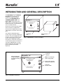
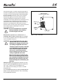
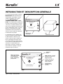
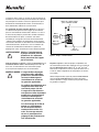
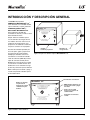
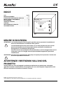
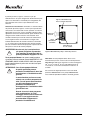
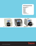
1
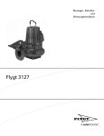
®
®
OPERATING MANUAL:
®
®
Compact Pump Drives
Masterflex L/s
®
MANUEL DE L’UTILISATEUR :
®
COMPACT DRIVE
Use only MASTERFLEX precision
tubing with MASTERFLEX pumps
to ensure optimum performance.
Use of other tubing may void
applicable warranties.
®
POWER
MAX
®
Entrainements de
Pompes Compacts
For use with L/S 13, L/S 14, and L/S 16 size
tubing in all formulations.
For L/S 17 and L/S 25 size tubing
use silicone or C-Flex tubing only.
BEDIENUNGSANLEITUNG:
®
®
Compact Pumpenantriebe
Model No.
Nº de modèle
Modellnummern
Modelo No.
Modello No.
77200-12
77200-20
MANUAL DE OPERACIÓN:
®
®
Propulsores de Bombas
Compactos
MANUALE dI ISTRUZIONI:
®
®
Azionamenti Compatti per
Pompe
A-1299-1007
Edition 02
1-800-MASTERFLEX (627-8373) (U.S. and Canada only) • 11 (847) 549-7600 (Outside U.S.)
(847) 549-7600 (Local) • www.masterflex.com • [email protected]
Thermo Fisher Scientific
1-800-637-3739 (U.S. and Canada only) • 11 (847) 381-7050 (Outside U.S.)
(847) 381-7050 (Local) • www.thermoscientific.com • [email protected]
®
®
TABLE OF CONTENTS
Title
Page
SAFETY PRECAUTIONS ........................................................2
INTRODUCTION AND GENERAL DESCRIPTION .............3-4
SETUP AND DRIVE OPERATION ..........................................5
MAINTENANCE ......................................................................5
SPECIFICATIONS ...................................................................5
WARRANTY ............................................................................6
PRODUCT RETURN ...............................................................6
TECHNICAL ASSISTANCE ....................................................6
Masterflex L/s
®
®
COMPACT DRIVE
Use only MASTERFLEX precision
tubing with MASTERFLEX pumps
to ensure optimum performance.
Use of other tubing may void
applicable warranties.
POWER
MAX
For use with L/S 13, L/S 14, and L/S 16 size
tubing in all formulations.
For L/S 17 and L/S 25 size tubing
use silicone or C-Flex tubing only.
SAFETY PRECAUTIONS
CAUTION: Use of Pump Heads other than those specified will result in unsatisfactory performance,
damage to the drive unit and voiding of applicable warranties.
!
The drive system can only be used with one Pump Head at a time. Use of this drive unit
with multiple Pump Heads will result in unsatisfactory performance, damage to the drive unit
and voiding of applicable warranties.
When mounting the Pump Head to the drive unit, the mounting screws should only be tightened
fingertight. Excessive tightening of the mounting screws will result in binding and unsatisfactory
performance.
WARNING: Be sure the Pump Drive is turned off before proceeding. Loose clothing could be caught
in the drive.
!
WARNING: PRODUCT USE LIMITATION
These products are not designed for, nor intended for use in patient-connected applications, including,
but not limited to, medical and dental use and, accordingly, have not been submitted for FDA approval.
C-FLEX — Reg TM Saint-Gobain Performance Plastics Corp.
Trademarks bearing the ® symbol in this publication are registered in the U.S. and in other countries.
2
®
®
INTRODUCTION AND GENERAL DESCRIPTION
The MASTERFLEX® L/S® COMPACT
Pump Drives are designed as an
inexpensive variable speed drive
which accepts MASTERFLEX L/S
STANDARD, QUICK LOAD® and
EASY-LOAD® Pump Heads. These
200 rpm drives accommodate one Pump
Head and one tube at controlled speed
as low as 30 rpm. All units
operate from an external Power Supply.
The AC models are supplied with a
Universal Power Supply which provides
a DC output for connection to the Pump
Drive.
The single-turn adjustable Speed
Control, Figure 2, provides variable flow
operation. The green POWER On indicator lights whenever the pump is operating. The Power On/Direction Switch
turns power on when either clockwise or
counterclockwise pump rotor direction is
selected. The MAX Button is used for
priming and purging and operates the
pump at maximum speed while
depressed.
Masterflex L/s
®
POWER
Use only MASTERFLEX precision
tubing with MASTERFLEX pumps
to ensure optimum performance.
Use of other tubing may void
applicable warranties.
MAX
For use with L/S 13, L/S 14, and L/S 16 size
tubing in all formulations.
For L/S 17 and L/S 25 size tubing
use silicone or C-Flex tubing only.
Universal Power
Supply
Pump Drive
Unit
Figure 1. MASTERFLEX L/S Compact Pump Drive
Masterflex L/s
®
Pump mounting holes,
accept all standard
8-32 pump mounting
hardware
®
COMPACT DRIVE
Power On
Indicator
®
COMPACT DRIVE
Use only MASTERFLEX precision
tubing with MASTERFLEX pumps
to ensure optimum performance.
Use of other tubing may void
applicable warranties.
POWER
MAX: Press and hold to
prime or purge pump
MAX
Speed control: provides
variable flow adjustment
Power On/
direction switch
For use with L/S 13, L/S 14, and L/S 16 size
tubing in all formulations.
For L/S 17 and L/S 25 size tubing
use silicone or C-Flex tubing only.
Figure 2. Pump Drive—Front Panel
3
®
®
The rear panel, Figure 3, contains a DC power input jack for
connection of primary power and a 4-terminal barrier strip for
connection of remote start/stop and for a DC backup supply.
Remote Start/Stop: Terminals 3 and 4 on the rear panel
terminal strip, (Figure 3) are used for remote start/stop
operation. Pump direction and speed are not remotely
controllable. In non-remote operation, these terminals are connected together by a shorting bar. For remote control by
switch closure, remove the shorting bar and connect the two
terminals of an isolated remote control switch or relay to
terminals 3 and 4. A closure of the remote switch contacts will
turn the pump system on. Opening the contact will
turn the pump system off.
WARNING: Be sure the Pump Drive is turned off
before proceeding. Loose clothing
could be caught in the drive.
DC Power Input,
2.5 mm Coaxial Receptacle
Backup
DC
Input
Remote
Start/Stop
Input
!
Pump Heads Accepted: Only the MASTERFLEX L/S
STANDARD, QUICK LOAD and EASY-LOAD are acceptable
for use with this pump drive. Only one Pump Head at a time
can be used with this drive unit.
CAUTIONS: Use of Pump Heads other than those
specified will result in unsatisfactory
performance, damage to the drive unit
and voiding of applicable warranties.
!
The drive system can only be used with
one Pump Head at a time. Use of this
drive unit with multiple Pump Heads
will result in unsatisfactory performance, damage to the drive unit and
voiding of applicable warranties.
When mounting the Pump Head to the
drive unit, the mounting screws should
only be tightened fingertight. Excessive
tightening of the mounting screws will
result in binding and unsatisfactory performance.
Tubing Accepted: The Pump Heads accepted for use with
drive can be used with MASTERFLEX precision tubing sizes
L/S® 13, L/S® 14 and L/S® 16 in all formulations. For
L/S® 17 and L/S® 25 size tubing, use silicone or C-FLEX®
formulations only.
Use only MASTERFLEX precision tubing with MASTERFLEX
pumps to ensure optimum performance. Use of other tubing
may void applicable warranties.
4
Shorting Bar
Figure 3. Pump — Rear Panel
®
SETUP AND DRIVE
OPERATION
1. Unpack the drive: save packaging material until proper product operation has been verified.
2. Select and mount Pump Head and load tubing
(see Pump Head manual).
3. For 77200-20 plug in Universal Power supply and connect
to the back of the drive. (See Figure #3.)
4. For 77200-12 supply 11.0 to 15V DC to terminal strip
positions 1 and 2. (See Figure #3.)
5. The drive system can be set to operate in either a clockwise
or a counterclockwise direction. The same control used to
select direction also turns power on or off. To
operate in a clockwise direction place direction control
switch in the "up" position. The POWER indicator should
light and the fluid will flow from right to left. To operate in
a counterclockwise direction, place direction switch in the
"down" position. The POWER indicator should light and
the fluid will flow from left to right. To turn pump off, place
switch in the "center" position.
6. The pump speed is controlled by the variable speed control.
Turning the control clockwise increases the speed. Tubing
life is decreased with increased operating speed. Speed can
be controlled up to a 6:1 range.
MAINTENANCE
Cleaning: Keep the drive enclosure clean with mild
detergents. Never immerse nor use excessive fluid.
Motor/ Brush Replacement: The motor used in this
inexpensive drive is not serviceable or repairable and has
brushes which cannot be replaced. The motor is rated for
a continuous duty life of 3000 operating hours minimum.
Operation at other than continuous duty cycles will result in
longer motor life. If motor failure for whatever reason occurs,
the motor must be replaced.
®
SPECIFICATIONS
Output:
Operating Speed:
Number of Pump Heads:
Torque Load:
Direction of rotation:
35 to 200 rpm
1
20 oz-in, maximum
Clockwise and Counterclockwise
Input:
Operating Voltage/Frequency:
Model 77200-20
115V AC nominal, 50/60 Hz
(90–130VAC) @500 mA AC
230V AC nominal, 50/60 Hz
(190–260VAC) @300 mA AC
Model 77200-12
Installation Category:
Model 77200-12 & -20
Remote Start/Stop:
13.5V DC nominal
(11.0–15.0V DC) @ 2.4 A DC
Category I per IEC664 (Signal Level)
Contact closure connection at
terminal strip contacts 3 and 4
Construction:
Dimensions (L × W × H):
Weight:
Color:
Material:
5.750 in × 5.14 in × 4.14 in
(14.6 cm × 13.0 cm × 10.5 cm)
1.88 pounds (0.85 kg)
Black
Painted Steel
Enclosure Rating:
IP22 per IEC529
Environment:
Operating Temperature:
Storage Temperature:
Humidity (Non-cond):
Altitude:
Pollution Degree:
32°F to 104°F (0°C to 40°C)
–49°F to 149°F (–45°C to 65°C)
10% to 90%
6600 ft (2000 m)
Pollution Degree 2 per IEC664
(Indoor usage — lab, office)
Compliance (For CE Mark):
EN61326-1/A2: 2001 (EMC Directive)
Converter is UL listed and CSA approved.
Regulatory agency specifications not applicable to the
balance of the unit due to low voltage.
5
®
WARRANTY
Use only MASTERFLEX precision tubing with
MASTERFLEX pumps to ensure optimum
performance. Use of other tubing may void
applicable warranties.
The Manufacturer warrants this product to be free from
significant deviations from published specifications. If repair or
adjustment is necessary within the warranty period, the problem will be corrected at no charge, if it is not due to
misuse or abuse on your part, as determined by the
Manufacturer. Repair costs outside the warranty period,
or those resulting from product misuse or abuse, may be
invoiced to you.
The warranty period for this product is one (1) year from
the date of purchase.
PRODUCT RETURN
To limit charges and delays, contact the seller or Manufacturer
for authorization and shipping instructions before returning the
product, either within or outside of the warranty period. When
returning the product, please state
the reason for the return. For your protection, pack the
product carefully and insure it against possible damage
or loss. Any damages resulting from improper packaging
are your responsibility.
TECHNICAL
ASSISTANCE
If you have any questions about the use of this product,
contact the Manufacturer or authorized seller.
6
®
®
®
OPERATING MANUAL:
®
®
Compact Pump Drives
Masterflex L/s
®
MANUEL DE L’UTILISATEUR :
®
COMPACT DRIVE
Use only MASTERFLEX precision
tubing with MASTERFLEX pumps
to ensure optimum performance.
Use of other tubing may void
applicable warranties.
For use with L/S 13, L/S 14, and L/S 16 size
tubing in all formulations.
For L/S 17 and L/S 25 size tubing
use silicone or C-Flex tubing only.
®
POWER
MAX
®
Entrainements de
Pompes Compacts
BEDIENUNGSANLEITUNG:
®
®
Compact Pumpenantriebe
Model No.
Nº de modèle
Modellnummern
Modelo No.
Modello No.
77200-20
77200-12
MANUAL DE OPERACIÓN:
®
®
Propulsores de Bombas
Compactos
MANUALE dI ISTRUZIONI:
®
®
Azionamenti Compatti per
Pompe
A-1299-1007
Édition 02
1-800-MASTERFLEX (627-8373) (U.S. and Canada only) • 11 (847) 549-7600 (Outside U.S.)
(847) 549-7600 (Local) • www.masterflex.com • [email protected]
Thermo Fisher Scientific
1-800-637-3739 (U.S. and Canada only) • 11 (847) 381-7050 (Outside U.S.)
(847) 381-7050 (Local) • www.thermoscientific.com • [email protected]
7
®
®
TABLE DES MATIÈRES
Titre
Page
CONSIGNES DE SECURITE ..................................................8
INTRODUCTION ET DESCRIPTION GENERALE ............9-10
INSTALLATION ET FONCTIONNEMENT
DE L’ENTRAINEMENT .........................................................11
ENTRETIEN...........................................................................11
CARACTERISTIQUES TECHNIQUES..................................11
GARANTIE.............................................................................12
RETOUR DE MARCHANDISES ...........................................12
ASSISTANCE TECHNIQUE..................................................12
Masterflex L/s
®
®
COMPACT DRIVE
Use only MASTERFLEX precision
tubing with MASTERFLEX pumps
to ensure optimum performance.
Use of other tubing may void
applicable warranties.
POWER
MAX
For use with L/S 13, L/S 14, and L/S 16 size
tubing in all formulations.
For L/S 17 and L/S 25 size tubing
use silicone or C-Flex tubing only.
CONSIGNES DE SECURITE
MISES EN GARDE: l'usage de têtes de pompes autres que celles spécifiées produirait un fonctionnement
incorrect, endommagerait l’entraînement et annulerait les garanties applicables.
!
Le système d’entraînement peut uniquement être utilisé avec une tête de pompe
à la fois. L'usage de cet entraînement avec plusieurs têtes de pompes produirait
un fonctionnement incorrect, endommagerait l’entraînement et annulerait les garanties
applicables.
Lors du montage de la tête de pompe sur l’entraînement, les vis de fixation doivent
seulement être serrées à la main. Tout serrage excessif de ces vis provoquerait
un grippage et des performances non satisfaisantes.
AVERTISSEMENT: vérifier si l’entraînement de la pompe est éteint avant de commencer. Les vêtements
lâches pourraient être happés par l’entraînement.
!
AVERTISSEMENT:
LIMITES D’UTILISATION DES PRODUITS
Ces produits ne sont pas conçus pour être utilisés dans des applications avec patients, y compris, entre
autres, les applications médicales et dentaires, et ne sont pas destinés à cet effet. Ils n’ont par conséquent
pas été soumis à l’agrément de la FDA.
C-FLEX — Reg TM Saint-Gobain Performance Plastics Corp.
Les marques accompagnées du symbole ® qui apparaissent dans cette publication sont déposées aux États-Unis et dans d’autres pays.
8
®
®
INTRODUCTION ET DESCRIPTION GENERALE
Les entraînements de pompes compacts
MASTERFLEX® L/S® représentent des
entraînements économiques à vitesse
variable, compatibles avec les têtes
de pompe MASTERFLEX L/S
STANDARD, QUICK LOAD® et EASYLOAD®. Ces entraînements de 200 tr/min
reçoivent une tête de pompe et un tuyau
à une vitesse contrôlée minimale de 30
tr/min. Tous les appareils fonctionnent sur
un bloc d'alimentation externe. Les modèles de c.a. sont fournis avec un bloc
d’alimentation externe qui produit une
sortie de courant continu pour alimenter
l’entraînement de la pompe.
La commande de vitesse réglable à un
seul tour (voir figure 2) permet d'obtenir
un débit variable. Le témoin vert de
marche s’allume lorsque la pompe fonctionne. L’interrupteur de marche et de
sens permet d’allumer la pompe lorsque
le sens horaire ou antihoraire du rotor est
sélectionné. Le bouton MAX sert à
l'amorçage et à la purge, et permet de
faire fonctionner la pompe à la vitesse
maximale lorsqu'il est enfoncé.
Masterflex L/s
®
POWER
Use only MASTERFLEX precision
tubing with MASTERFLEX pumps
to ensure optimum performance.
Use of other tubing may void
applicable warranties.
MAX
For use with L/S 13, L/S 14, and L/S 16 size
tubing in all formulations.
For L/S 17 and L/S 25 size tubing
use silicone or C-Flex tubing only.
Entraînement
de la pompe
Masterflex L/s
®
Orifices de montage
de la pompe, accepte
tout le matériel de
fixation standard des
pompes 8-32.
®
COMPACT DRIVE
Bloc
d’alimentation externe
Témoin de
marche
®
COMPACT DRIVE
Use only MASTERFLEX precision
tubing with MASTERFLEX pumps
to ensure optimum performance.
Use of other tubing may void
applicable warranties.
For use with L/S 13, L/S 14, and L/S 16 size
tubing in all formulations.
For L/S 17 and L/S 25 size tubing
use silicone or C-Flex tubing only.
POWER
MAX: maintenir ce bouton
appuyé pour amorcer ou
purger la pompe.
MAX
Contrôle de la vitesse:
permet de régler des
débits variables.
Interrupteur de
marche / sens de
la pompe
Figure 2. Pompe — Panneau avant
9
®
®
Le panneau arrière, figure 3, contient une prise d’entrée d’alimentation en courant continu pour branchement de l’alimentation principale et un bornier à cloison à quatre bornes pour
branchement d’un dispositif de marche / arrêt à distance et
d’une alimentation auxiliaire en courant continu.
La commande de marche/arrêt à distance: Les bornes 3
et 4 du bornier du panneau arrière (figure 3) sont utilisées
pour une commande de marche/arrêt à distance. Le sens et
la vitesse de la pompe ne peuvent être contrôlés à distance.
En fonctionnement sur place, ces bornes sont reliées
ensemble par une tige de court-circuit. En fonctionnement
à distance par fermeture de commutateur, retirer la tige de
court-circuit et brancher les deux bornes du commutateur de
commande à distance aux bornes 3 et 4. La fermeture des
contacts du commutateur fera démarrer le système de
pompage. Par contre, l’ouverture du contact arrêtera la pompe.
AVERTISSEMENT: Vérifier si l’entraînement de
la pompe est éteint avant de
commencer. Les vêtements
lâches pourraient être happés
par les rouleaux.
!
Têtes de pompes acceptées: seules les MASTERFLEX L/S
STANDARD, QUICK LOAD et EASY-LOAD peuvent être utilisées avec cet entraînement. Une seule tête de pompe
à la fois peut être employée avec cet entraînement.
MISES EN GARDE: L'usage de têtes de pompes
autres que celles spécifiées
produirait un fonctionnement
incorrect, endommagerait
l’entraînement et annulerait
les garanties applicables.
!
Le système d’entraînement peut
uniquement être utilisé avec
une tête de pompe à la fois.
L'usage de cet entraînement
avec plusieurs têtes de pompes
produirait un fonctionnement
incorrect, endommagerait
l’entraînement et annulerait
les garanties applicables.
Lors du montage de la tête de
pompe sur l’entraînement,
les vis de fixation doivent
seulement être serrées à la
main. Tout serrage excessif
de ces vis provoquerait un
grippage et des performances
non satisfaisantes.
10
Entrée de courant continu,
prise coaxiale de 2,5 mm
Entrée
auxiliaire
de courant
continu
Entrée de
marche/ arrêt
à distance
Tige de
court-circuit
Figure 3. Pompe — Panneau arrière
Tuyaux acceptés: les têtes de pompes compatibles avec
cet entraînement peuvent être employées avec les tuyaux de
précision MASTERFLEX de tailles L/S® 13, L/S® 14 et L/S®
16 de toutes compositions. Pour les tuyaux de tailles L/S® 17
et L/S® 25, utiliser uniquement des compositions en silicone
ou C-FLEX®.
Utiliser uniquement des tuyaux de précision MASTERFLEX
avec les pompes MASTERFLEX pour assurer des performances optimales. L’usage d’autres tuyaux pourrait annuler
les garanties en vigueur.
®
INSTALLATION ET FONCTIONNEMENT DE
L’ENTRAINEMENT
1. Déballer l’entraînement: conserver le matériau d’emballage
tant que le fonctionnement de l’appareil n’a pas été vérifié.
2. Sélectionner et monter la tête de pompe, puis charger le
tuyau (voir notice de la tête de pompe).
3. Pour le 77200-20, brancher le bloc d’alimentation externe et
connecter au dos de l’entraînement. (Voir figure 3.)
4. Pour le 77200-12, fournir 11 à 15 V c.c. aux bornes.
(Voir figure 3.)
5. Le système d’entraînement peut fonctionner dans le sens
horaire ou dans le sens contraire. La commande employée
pour sélectionner le sens permet également de couper ou
d’allumer le contact. Pour un fonctionnement dans le sens
horaire, placer l’interrupteur de commande de sens vers le
haut. Le témoin d’alimentation s'allume alors et le liquide
coule de la droite vers la gauche. Pour un fonctionnement
dans le sens antihoraire, placer l’interrupteur de commande
de sens vers le bas. Le témoin d’alimentation s'allume alors
et le liquide coule de la gauche vers la droite. Pour arrêter la
pompe, l'interrupteur doit être placé en position centrale.
6. La vitesse de la pompe est contrôlée par la commande
de vitesse variable. Pour l’augmenter, il suffit de tourner
ce bouton dans le sens horaire. La durée de vie du tuyau
est réduite par une vitesse de fonctionnement accrue.
La vitesse peut être contrôlée jusqu’à une plage de 6/1.
ENTRETIEN
Nettoyage: l’enveloppe de l’entrainement doit étre maintenue
propre avec des détergents doux.
Remplacement du moteurs/des balais: le moteur de cet
entraînement économique n'est pas réparable et comporte
des balais qui ne peuvent pas être remplacés. La durée de
vie minimum standard en utilisation continue du moteur est de
3 000 heures de fonctionnement. Le fonctionnement non continu entraîne un accroissement de la durée de vie. En cas de
défaillance du moteur pour quelque raison que ce soit,
il doit être remplacé.
®
CARACTERISTIQUES
TECHNIQUES
Sortie:
Vitesse de fonctionnement:
Nombre de
têtes de pompes:
Couple:
Sens de rotation:
35 à 200 tr/min
1
1440 gm-cm, maximum
Sens horaire et sens antihoraire
Entrée:
Tension/Fréquence d’alimentation :
Modèle 77200-20
115 V c.a. nominale, 50/60 Hz
(90–130 V c.a.) à 500 mA c.a.
230 V c.a. nominale, 50/60 Hz
(190–260 V c.a.) à 300 mA c.a.
Modèle 77200-12
Catégorie d’installation:
Modèle 77200-12 & -20
Commande de marche/
arrêt à distance :
13,5 V c.c. nominale
(11-15 V c.c.) à 2,4 A c.c.
Catégorie I, conformément à
CEI664 (niveau de signal)
Connexion de la fermeture du
contact aux bornes 3 et 4
Construction:
Dimensions (L × l × H):
Poids:
Couleur:
Matériau :
Homologation de
l’enveloppe:
14,6 × 13 × 10,5 cm
(5,75 × 5,14 × 4,14 po)
0,85 kg
Noir
Acier peint
IP22, conformément à
la norme CEI529
Environnement:
Température de
fonctionnement :
Température de stockage :
Humidité
(sans condensation) :
Altitude:
Degré de pollution :
0 à 40 ºC (32 à 104 °C)
–45 à 65 ºC (–49 à 149 °F)
10 à 90 %
2000 m (6 600 pi)
Degré de pollution 2, conformément
à CEI664 (Utilisation à l’intérieur –
laboratoire, bureau)
Conformité (pour marque CE):
EN61326-1/A2: 2001
(Directive sur la compatibilité électromagnétique européenne)
Transformateur répertorié UL et homologué CSA. Les spécifications
de l’organisme de réglementation ne sont pas applicable
à l’équilibre de l’appareil en raison de la faible tension.
11
®
GARANTIE
Utiliser uniquement des tuyaux de précision
MASTERFLEX avec les pompes MASTERFLEX
pour assurer des performances optimales. L’usage
d’autres tuyaux pourrait annuler les garanties en
vigueur.
Le fabricant garantit ce produit contre tout écart significatif par
rapport aux spécifications publiées. Si des réparations
ou des réglages s’avèrent nécessaires pendant la période de
garantie, le problème sera résolu gratuitement s’il ne provient
pas, de l’avis du fabricant, d’un usage incorrect ou abusif par
l’utilisateur. Les frais de réparations effectuées en dehors de
la période de garantie, ou liées à un usage incorrect ou abusif
du produit, seront à la charge du client.
La durée de garantie de ce produit est à un (1) an à
compter de la date d’achat.
RETOUR DE
MARCHANDISES
Afin de limiter les frais et les délais, il convient de contacter
le vendeur ou le fabricant pour obtenir une autorisation
préalable et des instructions d’expédition avant de renvoyer le
produit, qu’il soit ou non couvert par la garantie. La raison du
retour doit être mentionnée pour tout produit renvoyé. Afin de
se protéger, le produit doit être emballé soigneusement et
assuré contre les risques de dommages ou de perte. Toute
détérioration provenant d’un emballage incorrect incombe au
client.
ASSISTANCE
TECHNIQUE
Pour toute question concernant l’utilisation de ce produit, contacter le fabricant ou le revendeur agréé.
12
®
®
®
OPERATING MANUAL:
®
®
Compact Pump Drives
Masterflex L/s
®
MANUEL DE L’UTILISATEUR :
®
COMPACT DRIVE
Use only MASTERFLEX precision
tubing with MASTERFLEX pumps
to ensure optimum performance.
Use of other tubing may void
applicable warranties.
POWER
MAX
®
®
Entrainements de
Pompes Compacts
For use with L/S 13, L/S 14, and L/S 16 size
tubing in all formulations.
For L/S 17 and L/S 25 size tubing
use silicone or C-Flex tubing only.
BEDIENUNGSANLEITUNG:
®
®
Compact Pumpenantriebe
Model No.
Nº de modèle
Modellnummern
Modelo No.
Modello No.
77200-20
77200-12
MANUAL DE OPERACIÓN:
®
®
Propulsores de Bombas
Compactos
MANUALE dI ISTRUZIONI:
®
®
Azionamenti Compatti per
Pompe
A-1299-1007
AUSGABE 02
1-800-MASTERFLEX (627-8373) (U.S. and Canada only) • 11 (847) 549-7600 (Outside U.S.)
(847) 549-7600 (Local) • www.masterflex.com • [email protected]
Thermo Fisher Scientific
1-800-637-3739 (U.S. and Canada only) • 11 (847) 381-7050 (Outside U.S.)
(847) 381-7050 (Local) • www.thermoscientific.com • [email protected]
13
®
®
INHALTSVERZEICHNIS
Titel
Seite
SICHERHEITSMASSNAHMEN ............................................14
EINFÜHRUNG UND ALLGEMEINE BESCHREIBUNG ......15-16
SMONTAGE UND AUFWEIST BETRIEB .............................17
WARTUNG ............................................................................17
TECHNISCHE DATEN ..........................................................17
GARANTIE.............................................................................18
WARENRÜCKSENDUNGEN ................................................18
TECHNISCHE BERATUNG ..................................................18
Masterflex L/s
®
®
COMPACT DRIVE
Use only MASTERFLEX precision
tubing with MASTERFLEX pumps
to ensure optimum performance.
Use of other tubing may void
applicable warranties.
POWER
MAX
For use with L/S 13, L/S 14, and L/S 16 size
tubing in all formulations.
For L/S 17 and L/S 25 size tubing
use silicone or C-Flex tubing only.
SICHERHEITSMASSNAHMEN
!
VORSICHTSHINWEISE: Bei Verwendung von anderen als den angegebenen Pumpenköpfen wird
die Leistung beeinträchtigt, die Antriebseinheit beschädigt, und die Garantie ungültig.
Das Antriebssystem kann jeweils nur für einen Pumpenkopf verwendet werden. Bei gleichzeitiger
Verwendung dieser Einheit mit mehreren Pumpenköpfen wird die Leistung beeinträchtigt, die
Antriebseinheit beschädigt und die Garantie ungültig.
Beim Anschließen des Pumpenkopfes an die Antriebseinheit sollten die Befestigungsschrauben
nur mit den Fingern festgedreht werden. Wenn die Schrauben zu stark eingedreht werden, führt
dies zum Blockieren und zu mangelhafter Leistung.
!
ACHTUNG!: VOR DEM WEITERMACHEN SICHERSTELLEN, DASS DER PUMPENANTRIEB
AUSGESCHALTET IST. ES BESTEHT GEFAHR, DASS SICH LOSE BEKLEIDUNG IM ANTRIEB
VERFÄNGT.
ACHTUNG! ANWENDUNGSEINSCHRÄNKUNGEN
Diese Geräte sind nicht für den Einsatz am Patienten vorgesehen und auch nicht für diesen Zweck bestimmt
(z.B. medizinischen oder zahnmedizinischen Bereich) und entsprechen demgemäß auch keinen FDA
(Food & Drug Administration) Normen.
C-FLEX — Reg TM Saint-Gobain Performance Plastics Corp.
Warenzeichen, die in dieser Publikation mit dem Symbol ® versehen sind, sind in den USA und anderen Ländern eingetragen.
14
®
®
EINFÜHRUNG und ALLGEMEINE BESCHREIBUNG
Die MASTERFLEX® L/S® COMPACT
Pumpenantriebe sind als preisgünstiger
Antrieb mit variabler Geschwindigkeit für
den Anschluss an MASTERFLEX L/S
STANDARD, QUICK LOAD® und
EASY-LOAD® Pumpenköpfe vorgesehen. An diese Antriebe mit 200 U/min
kann ein Pumpenkopf und ein Schlauch
für kontrollierte Drehzahlen bis zu nur 30
U/min angeschlossen werden. Alle
Einheiten werden von einem externen
Stromversorgungsgerät betrieben.
Die Wechselstrommodelle sind mit
einem externen Stromversorgungsgerät
ausgestattet, das eine
Gleichstromausgabe für die Verbindung
mit dem Pumpenantrieb aufweist.
Der um eine Drehung einstellbare
Geschwindigkeitsregler, Abbildung 2,
bietet variablen Förderbetrieb. Die grüne
PWR-Anzeige leuchtet, wenn die Pumpe
eingeschaltet ist.
Der Ein-/Richtungsschalter ermöglicht die
Versorgung mit Strom, wobei es keine
Rolle spielt, ob sich der Pumpenrotor
rechts oder links herum dreht. Die MAXTaste dient zum Füllen und Entleeren und
betreibt die Pumpe bei maximaler
Geschwindigkeit, solange diese Taste
gedrückt wird.
Masterflex L/s
®
Use only MASTERFLEX precision
tubing with MASTERFLEX pumps
to ensure optimum performance.
Use of other tubing may void
applicable warranties.
POWER
MAX
For use with L/S 13, L/S 14, and L/S 16 size
tubing in all formulations.
For L/S 17 and L/S 25 size tubing
use silicone or C-Flex tubing only.
Externes
Stromversorgungsgerät
Pumpenantriebseinheit
Abbildung 1. MASTERFLEX® L/S ® Compact Pumpenantrieb
Masterflex L/s
®
Pumpenmontageöffnungen für
alle standarmäßigen 8-32
Pumpenmontageteile.
®
COMPACT DRIVE
Einschaltanzeige
®
COMPACT DRIVE
Use only MASTERFLEX precision
tubing with MASTERFLEX pumps
to ensure optimum performance.
Use of other tubing may void
applicable warranties.
POWER
MAX: Zum Füllen oder Entleeren
der Pumpe gedrückt halten.
MAX
Geschwindigkeitskontrolle: Bietet
variable Fördermengeneinstellung.
Ein-/Richtungsschalter
For use with L/S 13, L/S 14, and L/S 16 size
tubing in all formulations.
For L/S 17 and L/S 25 size tubing
use silicone or C-Flex tubing only.
Abbildung 2. Pumpe — Frontkonsole
15
®
®
Rückseitenkonsole, Abbildung 3, enthält einen
Gleichstromeingang zum Anschließen des Primärstroms
und eine 4-polige Klemmleiste zum Anschließen der
Start/Stopp-Fernbedienung und eines ReserveGleichstromversorgungsgeräts.
Anschließen der Start-/Stopp-Fernbedienung
Die Pole 3 und 4 der Klemmleiste an der Rückwandkonsole,
Abbildung 3, sind für die Start-/Stopp-Fernbedienung
vorgesehen. Die Pumpenrichtung und die Geschwindigkeit
können nicht fernbedient werden. Beim Einsatz ohne
Fernbedienung werden diese Anschlüsse mit einer Brücke
kurzgeschlossen.
Für Fernbedienung bei Schalterschluss die Kurzschlussbrücke entfernen und die beiden Anschlüsse des
Fernbedienungsschalters mit den Anschlüssen 3 und 4
verbinden. Durch Schließen der Fernbedienungskontakte
wird das Pumpensystem gestartet. Beim Öffnen der
Kontakte wird das Pumpensystem gestoppt.
!
ACHTUNG!
Vor dem Weitermachen sicherstellen, dass
der Pumpenantrieb ausgeschaltet ist. Es
besteht Gefahr, dass sich lose Bekleidung
in den Rollen verfängt.
Geeignete Pumpenköpfe: Nur die MASTERFLEX L/S
STANDARD, QUICK LOAD und EASY-LOAD sind zur
Verwendung mit diesem Pumpenantrieb geeignet. Die
Antriebseinheit kann jeweils nur für einen Pumpenkopf
verwendet werden.
!
VORSICHTSHINWEISE: Bei Verwendung
von anderen als den angegebenen
Pumpenköpfen wird die Leistung
beeinträchtigt, die Antriebseinheit
beschädigt und die Garantie ungültig.
Das Antriebssystem kann jeweils nur
für einen Pumpenkopf verwendet
werden. Bei gleichzeitiger Verwendung
dieser Einheit mit mehreren
Pumpenköpfen wird die Leistung
beeinträchtigt, die Antriebseinheit
beschädigt und die Garantie ungültig.
Beim Anschließen des Pumpenkopfes
an die Antriebseinheit sollten die
Befestigungsschrauben nur mit den
Fingern festgedreht werden. Wenn die
Schrauben zu stark eingedreht werden,
führt dies zum Blockieren und zu
mangelhafter Leistung.
16
Gleichstromeingang
2,5-mm-Koaxialbuchse
ReserveGleichstromeingang
Start-/StoppFernbedienungseingang
Kurzschlussbrücke
Abbildung 3. Pumpe — Rückwandkonsole
Geeignete Schläuche: Die für die Verwendung mit diesem
Antrieb geeigneten Pumpenköpfe akzeptieren den Anschluss
von MASTERFLEX Präzisionsschläuchen in den Größen L/S®
13, L/S® 14 und L/S® 16 in allen Ausführungen. Für Schläuche
in den Größen L/S® 17 und L/S® 25 nur die Ausführungen in
Silikon oder C-FLEX® verwenden.
Um optimale Anwendungsergebnisse zu gewährleisten, sind
für MASTERFLEX Pumpen ausschließlich MASTERFLEX
Präzisionsschläuche zu verwenden. Der Einsatz anderer
Schläuche kann eine Verweigerung der Garantieleistung nach
sich ziehen.
®
®
MONTAGE UND BETRIEB
TECHNISCHE DATEN
1. Antrieb auspacken: Das Verpackungsmaterial aufbewahren,
bis der ordnungsgemäße Betrieb der Einheit bestätigt wird.
Ausgangsleistung:
2. Pumpenkopf wählen und Schlauch anschließen (siehe
Bedienungsanleitung des Pumpenkopfes).
3. Bei den Modellen 77200-20 das externe
Stromversorgungsgerät an den Netzstrom anschließen
und mit der Rückseite des Antriebs verbinden.
(Siehe Abbildung Nr. 3.)
4. Bei Stromversorgungsgerät 77200-12: 11,0 bis 15 V
Gleichstrom zu Klemmleistenpositionen 1 und 2. (Siehe
Abbildung Nr. 3.)
5. Das Antriebssystem kann entweder auf Betriebsrichtung im
Uhrzeigersinn (rechts herum) oder gegen den
Uhrzeigersinn (links herum) eingestellt werden. Derselbe
Regler, mit dem die Richtung gewählt wird, dient auch zum
Ein- und Ausschalten des Stroms. Zum Betreiben des
Geräts im Uhrzeigersinn den Richtungsschalter "nach oben"
stellen. Die POWER-Anzeige müsste nun leuchten, und die
Flüssigkeit fließt von rechts nach links. Zum Betreiben des
Geräts gegen den Uhrzeigersinn den Richtungsschalter
"nach unten" stellen. Die POWER-Anzeige müßte nun
leuchten, und die Flüssigkeit fließt von links nach rechts.
Zum Ausschalten der Pumpe den Schalter auf die "mittlere"
Position stellen.
6. Die Pumpgeschwindigkeit wird mit dem variablen
Geschwindigkeitsregler kontrolliert. Durch Drehen des
Reglers im Uhrzeigersinn wird die Geschwindigkeit erhöht.
Bei erhöhter Betriebsgeschwindigkeit verringert sich die
Schlauchlebensdauer. Die Geschwindigkeit kann bis zu
einem Bereich von 6:1 reguliert werden.
WARTUNG
REINIGUNG: Das Antriebsgehäuse mit milden reinigungsmitteln sauberhalten. Nicht in Flüssigkeit tauchen und nicht zu
viel Flüssigkeit verwenden.
Auswechseln des Motors/der Kohlebürste: Der bei diesem
preisgünstigen Antrieb verwendete Motor kann nicht gewartet
oder repariert werden und ist mit Bürsten ausgestattet, die
nicht ausgewechselt werden können. Die Nennleistung des
Motors ist für eine kontinuierliche Betriebsdauer von mindestens 3000 Stunden berechnet. Der Motor lebt länger, wenn
er nicht kontinuierlich verwendet wird. Der Motor ist
auszuwechseln, wenn er aus irgendeinem Grund ausfällt.
Drehzahl bei Betrieb:
Anzahl der Pumpenköpfe:
Drehmoment:
Drehrichtung:
35 bis 200 U/min
1
1440 g/cm, maximal
Im Uhrzeigersinn (rechts herum)
und gegen den Uhrzeigersinn
(links herum)
Eingang:
Betriebsspannung/Frequenz:
Modell 77200-20
115 V~ nominal 50/60 Hz
(90 - 130 V~) bei 500 mA
Wechselstrom
230 V~ nominal 50/60 Hz
(190 - 260 V~) bei 300 mA
Wechselstrom
Modell 77200-12
13,5 V Gleichstrom nominal
(11,0 - 15,0 V Gleichstrom) bei 2,
4 A Gleichstrom
Installationskategorie:
Modell 77200-12 & -20
Kategorie I nach IEC664
(Signalebene)
Externer Start/Stopp:
Kontaktschlussschaltung an
Klemmleisten 3 und 4
Konstruktion:
Abmessungen (L × B × H):
Gewicht:
Farbe:
Material:
Gehäusering:
14,6 cm × 13,0 cm × 10,5 cm)
0,85 kg
Schwarz
Lackierter Stahl
IP22 nach IEC529
Umweltbedingungen:
Betriebstemperatur:
Lagertemperatur:
Feuchtigkeit
(nicht kondensierend):
Höhe:
Umweltverschmutzungsgrad:
0 °C bis 40 °C
0 °C bis 65 °C
10 % bis 90 %
2000 m
Umweltverschmutzungsgrad
2 nach IEC664
(Verwendung in Innenräumen —
Labor, Praxis)
Einhaltung der Normen
(für CE-Zeichen):
EN61326-1/A2: 2001 (EMV-Richtlinie der EU)
Gleichrichter ist UL-aufgelistet und CSA-zugelassen.
Aufgrund der niedrigen Stromspannung treffen die Spezifikationen
der Aufsichtsbehörde zum Abgleichen der Einheit nicht zu.
17
®
GARANTIE
Um optimale Anwendungsergebnisse zu
gewährleisten, sind für MASTERFLEX Pumpen
ausschließlich MASTERFLEX Präzisionsschläuche
zu verwenden. Der Einsatz anderer Schläuche kann
eine Verweigerung der Garantieleistung nach sich
ziehen.
Reparaturkosten außerhalb der Garantiezeit oder aufgrund
von fehlerhaftem oder unsachgemäßem Gebrauch des
Produktes werden dem Kunden in Rechnung gestellt.
Die Garantie gilt für einen Zeitraum von ein (1) Jahr nach
dem Kaufdatum.
WARENRÜCKSENDUNGEN
Um Kosten und Verzögerungen so gering wie möglich zu
halten, lassen Sie sich in jedem Fall von Ihrem Fachhändler
oder dem Hersteller eine Rücksendegenehmigung und die
Versandanweisungen geben, bevor Sie Ware zurückschicken.
Geben Sie bitte den Rücksendegrund mit an. Verpacken Sie
die Ware sorgfältig und versichern Sie die Sendung gegen
Beschädigung bzw. Verlust. Für Transportschäden aufgrund
unsachgemäßer Verpackung haften Sie.
TECHNISCHE BERATUNG
Wenn Sie Fragen zur Anwendung dieses Produktes haben,
wenden Sie sich bitte an den Hersteller oder autorisierten
Fachhändler.
18
®
®
®
OPERATING MANUAL:
®
®
Compact Pump Drives
Masterflex L/s
®
MANUEL DE L’UTILISATEUR :
®
COMPACT DRIVE
Use only MASTERFLEX precision
tubing with MASTERFLEX pumps
to ensure optimum performance.
Use of other tubing may void
applicable warranties.
For use with L/S 13, L/S 14, and L/S 16 size
tubing in all formulations.
For L/S 17 and L/S 25 size tubing
use silicone or C-Flex tubing only.
®
POWER
MAX
®
Entrainements de
Pompes Compacts
BEDIENUNGSANLEITUNG:
®
®
Compact Pumpenantriebe
Model No.
Nº de modèle
Modellnummern
Modelo No.
Modello No.
77200-20
77200-12
MANUAL DE OPERACIÓN:
®
®
Propulsores de Bombas
Compactos
MANUALE dI ISTRUZIONI:
®
®
Azionamenti Compatti per
Pompe
A-1299-1007
Edition 02
1-800-MASTERFLEX (627-8373) (U.S. and Canada only) • 11 (847) 549-7600 (Outside U.S.)
(847) 549-7600 (Local) • www.masterflex.com • [email protected]
Thermo Fisher Scientific
1-800-637-3739 (U.S. and Canada only) • 11 (847) 381-7050 (Outside U.S.)
(847) 381-7050 (Local) • www.thermoscientific.com • [email protected]
19
®
®
CONTENIDO
Título
Página
PRECAUCIONES PARA SEGURIDAD.................................20
INTRODUCCIÓN Y DESCRIPCIÓN GENERAL .............21-22
CONFIGURACIÓN Y OPERACIÓN DEL PROPULSOR ......23
MANTENIMIENTO ................................................................23
ESPECIFICACIONES............................................................23
GARANTÍA ............................................................................24
DEVOLUCIÓN DEL PRODUCTO .........................................24
ASISTENCIA TÉCNICA ........................................................24
Masterflex L/s
®
®
COMPACT DRIVE
Use only MASTERFLEX precision
tubing with MASTERFLEX pumps
to ensure optimum performance.
Use of other tubing may void
applicable warranties.
POWER
MAX
For use with L/S 13, L/S 14, and L/S 16 size
tubing in all formulations.
For L/S 17 and L/S 25 size tubing
use silicone or C-Flex tubing only.
PRECAUCIONES PARA SEGURIDAD
!
PRECAUCIONES:
El uso de cabezales diferentes a los especificados tendrá como resultado un rendimiento poco satisfactorio, daños a la unidad de propulsión y la anulación de las garantías correspondientes.
El sistema de propulsión solamente puede usarse con un cabezal de bomba a la vez. El uso
de esta unidad de propulsión con múltiples cabezales tendrá como resultado un rendimiento poco
satisfactorio, daños a la unidad de propulsión y la anulación de las garantías
correspondientes.
Al montar el cabezal de la bomba en la unidad de propulsión, los tornillos de montaje deben
apretarse solo a mano. Si se aprietan demasiado los tornillos de montaje se producirá un agarrotamiento y el rendimiento no será satisfactorio.
!
ADVERTENCIA:
ANTES DE SEGUIR, ASEGURARSE QUE EL PROPULSOR DE LA BOMBA ESTÉ APAGADO.
LA ROPA SUELTA PUEDE ENGANCHARSE EN LOS RODILLOS.
ADVERTENCIA: LIMITACIÓN DE USO DEL PRODUCTO
Estos productos no están diseñados ni destinados para ser utilizados en aplicaciones conectadas a un
paciente, incluyendo las aplicaciones médicas y dentales, pero sin limitarse a las mismas, y por lo tanto no
se ha solicitado su aprobación a la FDA.
C-FLEX — Marca registrada de Saint-Gobain Performance Plastics Corp.
Las marcas registradas que llevan el símbolo ® en esta publicación están registradas en EE.UU. y en otros países.
20
®
®
INTRODUCCIÓN Y DESCRIPCIÓN GENERAL
Las bombas de propulsión
COMPACTAS MASTERFLEX® L/S®
están diseñadas con velocidad variable,
a precio reducido y aceptan cabezales
STANDARD, QUICK LOAD® y
EASY-LOAD® MASTERFLEX L/S.
Estos propulsores de 200 rpm
acomodan un cabezal y un tubo a velocidad controlada de hasta
30 rpm. Todas las unidades operan
con un suministro de energía externo.
Los modelos de CA se envían con un
suministro de energía externo, que
proporciona una salida de corriente de
CC para la conexión con el propulsor.
El control de velocidad ajustable y de
una sola espira, figura 2, proporciona
una operación de caudal variable.
Siempre que la bomba está en funcionamiento se enciende el indicador
verde de activación (PWR On). El interruptor de activación/sentido (Power
On/Direction) activa la potencia cuando
se selecciona el sentido del rotor de la
bomba bien sea en sentido de las agujas del reloj o dirección opuesta. El botón
MAX se utiliza para el cebado y purga, y
cuando está pulsado la bomba opera a
la velocidad máxima.
Masterflex L/s
®
POWER
Use only MASTERFLEX precision
tubing with MASTERFLEX pumps
to ensure optimum performance.
Use of other tubing may void
applicable warranties.
MAX
For use with L/S 13, L/S 14, and L/S 16 size
tubing in all formulations.
For L/S 17 and L/S 25 size tubing
use silicone or C-Flex tubing only.
Suministro de
energía externo
Unidad
bomba de propulsión
Figura 1. Propulsor de bomba compacto MASTERFLEX® L/S®
Masterflex L/s
®
Orificios de montaje,
aceptan toda la
tornillería de montaje
estándar 8-32 para
bombas.
®
COMPACT DRIVE
Indicador de activación
®
COMPACT DRIVE
Use only MASTERFLEX precision
tubing with MASTERFLEX pumps
to ensure optimum performance.
Use of other tubing may void
applicable warranties.
POWER
MAX: Oprimir y mantener presionado para cebar o purgar
la bomba.
MAX
Control de velocidad:
Proporciona un ajuste de
caudal variable.
Interruptor de activación/
sentido
For use with L/S 13, L/S 14, and L/S 16 size
tubing in all formulations.
For L/S 17 and L/S 25 size tubing
use silicone or C-Flex tubing only.
Figura 2. Bomba — Panel delantero
21
®
®
El panel trasero, figura 3, contiene un enchufe de potencia de
entrada de CC para la conexión de la energía eléctrica primaria
y una regleta de barrera de 4 conexiones para la conexión del
control remoto de inicio/parada y un suministro de CC auxiliar.
Control remoto de inicio/parada: Las terminales 3 y 4 en la
regleta de conexiones del panel trasero, figura 3, se utilizan
para la operación de inicio/parada por control remoto. El
sentido de la bomba y la velocidad no pueden controlarse a
distancia. Cuando la unidad funciona en un modo que no es
por control remoto, estas terminales se conectan juntas con
una barra de cortocircuitar.
Para controlar la unidad a distancia por medio del cierre del
interruptor, quitar la barra de cortocircuitar y conectar las
dos terminales del interruptor de control remoto a las
terminales 3 y 4. El cierre de los contactos del interruptor de
control remoto pone en marcha el sistema de bombas. La
apertura de los contactos detiene el sistema de bombas.
!
ADVERTENCIA:
Antes de seguir, asegurarse de que el
propulsor de la bomba esté apagado.
La ropa suelta puede engancharse en
los rodillos.
Cabezales de bomba aceptados: Cabezales de bomba
aceptados: Esta bomba de propulsión solamente acepta los
cabezales de bomba STANDARD, QUICK LOAD y EASYLOAD MASTERFLEX® L/S®. En esta unidad solo puede
usarse un cabezal a la vez.
!
PRECAUCIONES: El uso de cabezales
de bomba diferentes a los especificados
tendrá como resultado un rendimiento
poco satisfactorio, daños a la unidad de
propulsión y la anulación de las garantías correspondientes.
El sistema de propulsión solamente
puede usarse con un cabezal a la vez. El
uso de esta unidad de propulsión con
múltiples cabezales tendrá como resultado un rendimiento poco satisfactorio,
daños a la unidad de propulsión y la
anulación de las garantías correspondientes.
Al montar el cabezal en la bomba de
propulsión, los tornillos de montaje
deben apretarse solamente con la mano.
Si se aprietan demasiado se
producirá un agarrotamiento y el
rendimiento no será satisfactorio.
22
Potencia de entrada de CC,
Receptáculo coaxial de 2,5 mm
Entrada
de CC
auxiliar
Entrada
del control
remoto de
inicio/parada
Barra de cortocircuitar
Figura 3. Propulsor de bomba — Panel trasero
Mangueras aceptados: Los cabezales aceptados para su
uso con el propulsor pueden utilizarse con las manguernas de
precisión de tamaño L/S® 13, L/S® 14 y L/S® 16 en todas las
formulaciones. Para manguernas de tamaño L/S® 17 y L/S®
25, usar formulaciones de silicona o C-FLEX® solamente.
Usar solamente manguernas de precisión MASTERFLEX con
las bombas MASTERFLEX para asegurar el máximo
rendimiento. El uso de otras manguernas puede anular las
garantías correspondientes.
®
CONFIGURACIÓN Y
OPERACIÓN DEL
PROPULSOR
1. Desembalar el propulsor: guardar el material de embalaje
hasta que se haya verificado el funcionamiento correcto del
producto.
2. Seleccionar y montar el cabezal de la bomba y tubos de
carga (ver el manual del cabezal de la bomba).
3. Para los modelos 77200-20 enchufar en el suministro de
energía externo y conectar en la parte trasera del propulsor.
(Ver la figura nº 3.)
4. Para los modelos 77200-12 suministro de 11,0 a 15V CC
a las posiciones 1y 2 de la regleta de conexiones.
(Ver la figura nº 3.)
5.El sistema del propulsor puede fijarse para que opere tanto en
sentido de rotación del reloj u opuesto. El mismo control que
se utiliza para seleccionar el sentido también activa y desactiva la potencia. Para operar en sentido igual al reloj, colocar el
interruptor de control de sentido en la posición "up" (arriba).
Se encenderá el indicador de activación y el fluido fluirá de
derecha a izquierda. Para operar en sentido contrario,
colocar el interruptor de control de sentido en la posición
"down" (abajo). Se encenderá el indicador de activación y el
fluido fluirá de izquierda a derecha. Para apagar la bomba,
colocar el interruptor en la posición del "centro".
6. La velocidad de la bomba se controla con el control
de velocidad variable. Cuando se gira el control en el sentido
de rotación del reloj aumenta la velocidad. Una velocidad de
funcionamiento elevada reduce la duración del tubo. La velocidad puede controlarse hasta una gama de 6:1.
MANTENIMIENTO
Limpieza: Mantener la caja de la bomba limpia con
detergentes suaves.
®
ESPECIFICACIONES
Salida:
Velocidad operacional:
Número de cabezales
de bomba:
Carga de par:
Sentido de la rotación:
35 a 200 rpm
1
1440 gm-cm (20 oz-pulg.), máxima
Horario y antihorario
Entrada:
Voltaje de entrada /frecuencia:
Modelo 77200-20
Nominal de 115V CA 50/60 Hz
(90-130V CA) a 500mA CA
Nominal de 230V CA 50/60 Hz
(190-260V CA) a 300mA CA
Modelo 77200-12
Nominal de 13,5V CC
(11,0-15,0V CC) a 2,4A CC
Categoría de instalación:
Modelo 77200-12 & -20
Control remoto de
inicio/parada:
Categoría I según IEC664
(Nivel de señales)
Conexión de cierre de contactos en
las terminales 3 y 4 de la regleta
Construcción:
Dimensiones (L × A × A):
Peso:
Color:
14,6 cm × 13,0 cm × 10,5 cm
(5,750 pulg. × 5,14 pulg. × 4,14 pulg.)
0,85 kg (1,88 libras)
Negro
Material:
Acero pintado
Clasificación de la caja:
IP22 según IEC529
Ambiente:
Temperatura de
funcionamiento:
Temperatura de
almacenamiento:
Humedad
(sin condensación):
Altitud:
Grado de contaminación:
0 °C a 40 °C (32 °F a 104 °F)
-45 °C a 65°C (-49 °F a 149 °F)
10% a 90%
2000 m (6600 pies)
Grado de contaminación 2 según IEC664
(Uso en interiores — laboratorio, oficina)
Conformidad (Para marca de CE):
EN61326-1/A2: 201 (Directiva EU EMC)
El convertidor está listado en UL y aprobado por CSA.
Las especificaciones del organismo de control no aplican al equilibrio
de la unidad debido al bajo voltaje.
Motor/ Cambio de escobillas: El motor que se utiliza en
esta unidad no admite mantenimiento ni reparaciones y tiene
escobillas, que no pueden cambiarse. El motor está determinado para una duración útil continua de un mínimo de 3000
horas de funcionamiento. La operación en ciclos de trabajo
que no sean continuos tendrá como resultado una duración
más prolongada del motor. Si falla el motor por cualquier
razón, debe ser reemplazado.
23
®
GARANTÍA
!
Usar solamente mangueras de precisión
MASTERFLEX con las bombas
MASTERFLEX para asegurar el máximo
rendimiento. El uso de otros tubos puede
anular las garantías correspondientes.
El Fabricante garantiza que las especificaciones de este producto no se desvían significativamente de las especificaciones publicadas. Si es necesario hacer una reparación o un
ajuste en el período de garantía, el problema será corregido
de forma gratuita si no se debe a uso indebido o abuso por
parte del usuario, según lo determine el Fabricante. Los costos de reparación fuera del período de garantía o aquellos
resultantes del uso indebido o abuso del producto podrán cargarse al usuario.
El período de garantía de este producto es una (1) año a
partir de la fecha de compra.
DEVOLUCIÓN DEL
PRODUCTO
Para limitar cargos y retrasos, ponerse en contacto con el
vendedor o Fabricante para recibir la autorización e instrucciones de envío con anterioridad a la devolución del producto,
bien sea dentro o fuera del período de garantía. Al devolver el
producto, indicar el motivo de la devolución. Para protección
del usuario, embalar bien el producto y asegurarlo contra
posibles daños o pérdidas. El usuario es responsable de los
daños resultantes de un embalaje incorrecto.
ASISTENCIA TÉCNICA
Si se tiene alguna duda sobre el uso de este producto, ponerse en contacto con el Fabricante o vendedor autorizado.
24
®
®
®
OPERATING MANUAL:
®
®
Compact Pump Drives
Masterflex L/s
®
MANUEL DE L’UTILISATEUR :
®
COMPACT DRIVE
Use only MASTERFLEX precision
tubing with MASTERFLEX pumps
to ensure optimum performance.
Use of other tubing may void
applicable warranties.
For use with L/S 13, L/S 14, and L/S 16 size
tubing in all formulations.
For L/S 17 and L/S 25 size tubing
use silicone or C-Flex tubing only.
®
POWER
MAX
®
Entrainements de
Pompes Compacts
BEDIENUNGSANLEITUNG:
®
®
Compact Pumpenantriebe
Model No.
Nº de modèle
Modellnummern
Modelo No.
Modello No.
77200-20
77200-12
MANUAL DE OPERACIÓN:
®
®
Propulsores de Bombas
Compactos
MANUALE dI ISTRUZIONI:
®
®
Azionamenti Compatti per
Pompe
A-1299-1007
Edizione 02
1-800-MASTERFLEX (627-8373) (U.S. and Canada only) • 11 (847) 549-7600 (Outside U.S.)
(847) 549-7600 (Local) • www.masterflex.com • [email protected]
Thermo Fisher Scientific
1-800-637-3739 (U.S. and Canada only) • 11 (847) 381-7050 (Outside U.S.)
(847) 381-7050 (Local) • www.thermoscientific.com • [email protected]
25
®
®
INDICE
Titolo
Pagina
MISURE DI SICUREZZA ......................................................26
INTRODUZIONE E DESCRIZIONE GENERALE ............27-28
MESSA A PUNTO E AZIONAMENTO..................................29
MANUTENZIONE..................................................................29
SPECIFICHE TECNICHE......................................................29
GARANZIA ............................................................................30
RESTITUZIONE DEL PRODOTTO .......................................30
ASSISTENZA TECNICA .......................................................30
Masterflex L/s
®
®
COMPACT DRIVE
Use only MASTERFLEX precision
tubing with MASTERFLEX pumps
to ensure optimum performance.
Use of other tubing may void
applicable warranties.
POWER
MAX
For use with L/S 13, L/S 14, and L/S 16 size
tubing in all formulations.
For L/S 17 and L/S 25 size tubing
use silicone or C-Flex tubing only.
MISURE DI SICUREZZA
ATTENZIONE: l'uso di teste pompanti diverse da quelle specificate provoca prestazioni insoddisfacenti,
danni alla motorizzazione e l'invalidazione delle garanzie.
!
La motorizzazione può essere usata soltanto con una testa pompante alla volta. L’uso di
questa motorizzazione con più teste pompanti provoca prestazioni insoddisfacenti,
danneggiamenti e l'invalidazione delle garanzie.
Quando si monta la testa pompante sulla motorizzazione, le viti di montaggio devono essere
strette solo a mano. Un serraggio eccessivo provocherebbe inceppamenti e prestazioni
insoddisfacenti.
AVVERTENZA: assicurarsi che la motorizzazione della pompa sia spenta prima di procedere. I lembi sciolti
del vestiario potrebbero incastrarvisi.
!
AVVERTENZE: RESTRIZIONI SULL’USO DEL
PRODOTTO
Questi prodotti non sono stati progettati o realizzati per applicazioni con pazienti come, ad esempio,
applicazioni mediche od odontoiatriche. Di conseguenza, non sono stati sottoposti all’approvazione della
FDA (ente statunitense di controllo su alimenti e i farmaci).
C-FLEX – Reg TM Saint-Gobain Performance Plastics Corp.
I marchi di fabbrica recanti il simbolo ® in questa pubblicazione sono registrati negli Stati Uniti e in altri paesi.
26
®
®
INTRODUZIONE E DESCRIZIONE GENERALE
Le motorizzazioni per pompe
MASTERFLEX® L/S® COMPATTE
sono state progettate al fine di realizzare
azionamenti a velocità variabile a
basso costo per le teste pompanti
MASTERFLEX L/S STANDARD, QUICK
LOAD® e EASY-LOAD®. Queste
motorizzazioni a 200 giri/1' operano con
una testa pompante e un tubo a velocità
controllata fino ad un minimo di 30 giri/1'.
Tutte le unità sono alimentate da un alimentatore esterno. I modelli da CA sono
alimentate da un alimentatore esterno
che fornisce una uscita a CC per
il collegamento alla motorizzazione
della pompa.
Masterflex L/s
®
®
COMPACT DRIVE
Use only MASTERFLEX precision
tubing with MASTERFLEX pumps
to ensure optimum performance.
Use of other tubing may void
applicable warranties.
POWER
MAX
For use with L/S 13, L/S 14, and L/S 16 size
tubing in all formulations.
For L/S 17 and L/S 25 size tubing
use silicone or C-Flex tubing only.
Motorizzazione
pompa
Alimentatore
esterno
Il comando della velocità regolabile, a giro
singolo, Figura 2, consente di regolare la
Figura 1. Motorizzazione pompa MASTERFLEX® L/S® Compatta
portata. La spia verde PWR On (acceso),
si illumina ogni volta che la pompa è in funzione. L’interruttore Power On/Direction
(acceso/direzione) alimenta l’apparecchio
quando si seleziona il senso di rotazione
del rotore della pompa, orario o antiorario.
Il pulsante MAX serve per effettuare le
operazioni di adescamento e spurgo.
Inoltre, mentre viene tenuto premuto,
fa funzionare la pompa alla velocità
massima.
Masterflex L/s
®
Fori di montaggio
predisposti per
bulloneria standard
per pompe 8-32.
Spia di
accensione
®
COMPACT DRIVE
Use only MASTERFLEX precision
tubing with MASTERFLEX pumps
to ensure optimum performance.
Use of other tubing may void
applicable warranties.
For use with L/S 13, L/S 14, and L/S 16 size
tubing in all formulations.
For L/S 17 and L/S 25 size tubing
use silicone or C-Flex tubing only.
POWER
MAX: Tenere premuto per
innescare o eseguire lo spurgo
della pompa.
MAX
Comando velocità: permette
di regolare la portata.
Interruttore Power
On/Direction
(acceso/direzione)
Figura 2. Pompa — Pannello anteriore
27
®
®
Il pannello posteriore, Figura 3, contiene un jack per
l’alimentazione in CC per il collegamento all’alimentazione principale e una morsettiera a 4 terminali per il collegamento del
telecomando di avvio /arresto e per l'alimentatore in CC
di riserva.
Avvio/arresto telecomando: I terminali 3 e 4 sulla morsettiera
nel pannello posteriore, Figura 3, servono per le operazioni di
avvio/arresto con telecomando. Il senso operativo e la velocità
della pompa non possono essere comandati a distanza. Nelle
applicazioni senza l'uso del telecomando, questi terminali sono
collegati assieme tramite una barra cortocircuitante. Per il
comando a distanza per mezzo di chiusura di commutazione
occorre togliere la barra cortocircuitante e collegare i due
terminali dell’interruttore di comando a distanza ai terminali 3
e 4. La chiusura dei contatti dell’interruttore del telecomando
provoca l'avviamento del sistema pompante. L’apertura del contatto provoca l'arresto del sistema pompante.
AVVERTENZA: Assicurarsi che la motorizzazione
sia spenta (Off) prima di procedere.
Fare attenzioni ai lembi degli abiti in
quanto potrebbero impigliarsi nei rulli
!
Teste pompanti idonee: con questa motorizzazione
si possono utilizzare soltanto le teste MASTERFLEX L/S
STANDARD, QUICK LOAD e EASY-LOAD. Con questo
tipo di motorizzazione si può usare una sola testa pompante alla volta.
ATTENZIONE: l'uso di teste pompanti diverse
da quelle specificate provoca
prestazioni insoddisfacenti, danni alla
motorizzazione e l'invalidazione delle
garanzie.
!
La motorizzazione può essere usata
soltanto con una testa pompante alla
volta. L’uso di questa motorizzazione
con più teste pompanti provoca
prestazioni insoddisfacenti,
danneggiamenti e l'invalidazione delle
garanzie del caso.
Quando si monta la testa pompante
sulla motorizzazione, le viti di
montaggio devono essere strette solo
a mano. Un serraggio eccessivo
provocherebbe inceppamenti e
prestazioni insoddisfacenti.
28
Ingresso alimentazione CC;
Presa coassiale da 2,5 mm
Input in CC
di riserva
Input
avvio/arresto
a distanza
Barra di messa
in corto circuito
Figura 3. Motorizzazione pompa — Pannello posteriore
Tubi idonei: le teste pompanti idonee all'uso con la
motorizzazione possono essere usate con tubi di precisione
MASTERFLEX delle misure seguenti e in tutte le formulazioni:
L/S® 13, L/S® 14 ed L/S® 16. Con i tubi di dimensioni L/S®
17 ed L/S® 25 , usare solo le formulazioni in silicone o in
C-FLEX®
Per assicurare le migliori prestazioni, usare solo tubi di
precisione MASTERFLEX con le pompe MASTERFLEX.
L’uso di altri tubi potrebbe invalidare le eventuali garanzie.
®
MESSA A PUNTO E
AZIONAMENTO
1. Sballare la motorizzazione: conservare l’imballaggio fino a
quando non si sia verificato il corretto funzionamento del
prodotto.
2. Selezionare e montare la testa pompante e il tubo di carico
(vedere il manuale della testa pompante).
3. Per i modelli 77200-20, inserire l’alimentatore esterno e collegarlo al retro della motorizzazione (Vedere Figure #3).
4. Per i modelli 77200-12, alimentare da 11,0 a 15V CC alle
posizioni 1 e 2 della morsettiera (vedere Figure #3).
5. La motorizzazione può essere impostata per operare in
senso orario o antiorario. Lo stesso comando usato per
scegliere il senso di rotazione serve anche per accendere
e spegnere l'apparato. Per operare in senso orario è
sufficiente posizionare il comando del senso di rotazione in
corrispondenza di "up" (in alto). La spia POWER si illumina
e il fluido scorre da destra a sinistra. Per operare in senso
antiorario è sufficiente posizionare il comando del senso di
rotazione in corrispondenza di "down" (in basso). La spia
POWER si illumina e il fluido scorre da sinistra a destra.
Per spegnere la pompa occorre posizionare l’interruttore
nella posizione centrale, "center".
6. Il comando della velocità variabile consente di selezionare
la velocità desiderata della pompa. Girando il comando in
senso orario si aumenta la velocità. Il funzionamento a
velocità elevata riduce la vita utile del tubo. La velocità
può essere controllata fino ad un range di 6:1.
®
SPECIFICHE TECNICHE
Uscita:
Velocità operativa:
Numero di teste pompanti:
Carico di coppia:
Senso di rotazione:
da 35 a 200 giri/1'
1
1440 gm-cm max. (20 once-1")
orario ed antiorario
Entrata:
Tensione/frequenza di operativa:
Modello 77200-00
115V CA nominali 50/60 Hz
(90-130V CA) a 500mA CA
230V CA nominali 50/60 Hz
(190-260V CA) a 300mA CA
Modello 77200-12
13,5V CC nominali
(11,0-15,0V CC) a 2,4A CC
Categoria di installazione:
Modello 77200-12 & -20
Categoria I secondo norma IEC664
(intensità del segnale)
Avvio/arresto telecomandato: Connessione chiusura contatto,
ai contatti della morsettiera 3 e 4
Costruzione:
Dimensioni (L × P × H):
Peso:
Colore:
Materiale:
Rating della scatola:
14,6 cm × 13,0 cm × 10,5 cm
(5,750" × 5,14" × 4,14")
0,85 kg (1,88 lb)
Nero
Acciaio verniciato
IP22 secondo norma IEC529
Ambiente:
Temperatura di esercizio:
Temperatura di stoccaggio:
Umidità (senza condensa):
Altitudine:
Grado di inquinamento:
da 0° a 40°C (da 32°F a 104°F)
da -45°C a 65°C (da -49°F a 149°F)
dal 10% al 90%
2.000 m
Grado di inquinamento 2 secondo
norma IEC664 (impieghi interni—
laboratori, uffici)
Conformità (al marchio CE):
MANUTENZIONE
PULIZIA: Tenere pulita la scatola della motorizzazione con
detergenti non aggressivi.
EN61326-1/A2: 2001
(Direttiva UE EMC)
Il convertitore è riportato negli elenchi UL ed è approvato dal CSA.
Le specifiche dell'ente normativo (regulatory agency) non sono
applicabili al resto dell'apparato a causa della bassa tensione.
Sostituzione del motore/spazzola: il motore installato in
questo tipo di motorizzazione a basso costo non è riparabile e
le sue spazzole non sono sostituibili. Il motore ha una vita utile
nominale pari ad almeno 3.000 ore di servizio continuo.
Il funzionamento in cicli di esercizio non continui prolunga la
vita utile del motore. Il motore deve essere sostituito in caso di
guasti, a prescindere dalla causa.
29
®
GARANZIA
Usare solo tubi di precisione MASTERFLEX, con le
pompe MASTERFLEX, per assicurare le migliori
prestazioni. L’uso di altri tubi potrebbe invalidare
le eventuali garanzie.
Il produttore garantisce che questo prodotto è esente da deviazioni significative rispetto alle specifiche tecniche
pubblicate. Eventuali interventi di regolazione o riparazione
verranno eseguiti gratuitamente durante il periodo di garanzia
a condizione che non siano stati causati da abuso o uso
errato dell'apparecchio da parte dell'utente, condizione che
verrà determinata dal produttore. I costi delle riparazioni che
non rientrano nel periodo di validità della garanzia, o che risultano da abuso o uso errato del prodotto, verranno
fatturati all’utente.
Il periodo di garanzia per questo prodotto è ad un (1)
anno dalla data di acquisto.
RESTITUZIONE DEL
PRODOTTO
Per ridurre spese e ritardi, prima di restituire il prodotto si
raccomanda di contattare il venditore o il produttore per
l’autorizzazione e le istruzioni di spedizione, sia entro che
fuori il periodo di garanzia. L'utente che restituisce il prodotto
è pregato di dichiararne il motivo. Si raccomanda di imballare
con cura il prodotto e assicurarlo contro danni o perdite.
L'utente si assume ogni responsabilità per eventuali danni
risultanti da un imballaggio inadeguato.
ASSISTENZA TECNICA
In caso di quesiti circa l’uso di questo prodotto si prega di
contattare il produttore o il rivenditore.
30
®
®
®
31
®
®
1-800-MASTERFLEX (627-8373)
(U.S. and Canada only)
11 (847) 549-7600 (Outside U.S.)
(847) 549-7600 (Local)
www.masterflex.com
[email protected]
Thermo Fisher Scientific
1-800-637-3739 (U.S. and Canada only)
11 (847) 381-7050 (Outside U.S.)
(847) 381-7050 (Local)
www.thermoscientific.com
[email protected]
Printed in U.S.A.
32