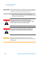
1
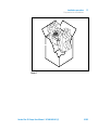
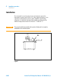
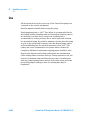
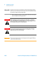
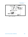
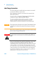
Vaclon Plus 25 Pumps Triode 911-5030 Diode 911-5036 Manuale di Istruzioni Bedienungshandbuch Notice de Mode D’Emploi User Manual 87-900-063-01 (F) 05/2011 Notices © Agilent Technologies, Inc. 2011 No part of this manual may be reproduced in any form or by any means (including electronic storage and retrieval or translation into a foreign language) without prior agreement and written consent from Agilent Technologies, Inc. as governed by United States and international copyright laws. Manual Part Number Publication Number: 87-900-063-01 (F) Edition Edition 05/2011 Printed in ITALY Agilent Technologies Italia S.p.A. Vacuum Products Division Via F.lli Varian, 54 10040 Leinì (TO) ITALY Warranty The material contained in this document is provided “as is,” and is subject to being changed, without notice, in future editions. Further, to the maximum extent permitted by applicable law, Agilent disclaims all warranties, either express or implied, with regard to this manual and any information contained herein, including but not limited to the implied warranties of merchantability and fitness for a particular purpose. Agilent shall not be liable for errors or for incidental or consequential damages in connection with the furnishing, use, or performance of this document or of any information contained herein. Should Agilent and the user have a separate written agreement with warranty terms covering the material in this document that conflict with these terms, the warranty terms in the separate agreement shall control. Technology Licenses The hardware and/or software described in this document are furnished under a license and may be used or copied only in accordance with the terms of such license. Restricted Rights Legend If software is for use in the performance of a U.S. Government prime contract or subcontract, Software is delivered and licensed as “Commercial computer software” as defined in DFAR 252.227-7014 (June 1995), or as a “commercial item” as defined in FAR 2.101(a) or as “Restricted computer software” as defined in FAR 52.227-19 (June 1987) or any equivalent agency regulation or contract clause. Use, duplication or disclosure of Software is subject to Agilent Technologies’ standard commercial license terms, and nonDOD Departments and Agencies of the U.S. Government will receive no greater than Restricted Rights as defined in FAR 52.227-19(c)(1-2) (June 1987). U.S. Government users will receive no greater than Limited Rights as defined in FAR 52.227-14 (June 1987) or DFAR 252.227-7015 (b)(2) (November 1995), as applicable in any technical data. Trademarks Windows and MS Windows are U.S. registered trademarks of Microsoft Corporation. Safety Notices CAUTION A CAUTION notice denotes a hazard. It calls attention to an operating procedure, practice, or the like that, if not correctly performed or adhered to, could result in damage to the product or loss of important data. Do not proceed beyond a CAUTION notice until the indicated conditions are fully understood and met. WARNING A WARNING notice denotes a hazard. It calls attention to an operating procedure, practice, or the like that, if not correctly performed or adhered to, could result in personal injury or death. Do not proceed beyond a WARNING notice until the indicated conditions are fully understood and met. Vaclon Plus 25 Pumps User Manual / 87-900-063-01 (F) Contents Contents 1 Procedura per l’installazione Informazioni generali 7 8 Preparazione per l’installazione 10 Installazione 12 Uso 14 Procedure di uso 15 Manutenzione 17 Smaltimento 2 18 Anleitung zur Installation Allgemeine Hinweise 19 20 Vor der Installation 22 Installation 24 Gebrauch 26 Bedienungsschritte 27 Wartung 29 Entsorgung 30 3 Procédure pour l’installation Indications Generales 31 32 Préparation pour l'installation Vaclon Plus 25 Pumps User Manual / 87-900-063-01 (F) 34 3/82 Contents Installation 36 Utilisation 38 Procédure d’utilisation 39 4 Maintenance 41 Mise au rebut 42 Installation procedure 43 General Information 44 Preparation for Installation 46 Installation 48 Use 50 Operating Procedure 51 Maintenance Disposal 5 53 54 Technical Information 55 Vaclon Plus Pump Controller 55 Description of the Vaclon Pump 56 Technical Specification 57 Outline Drawing 59 Stray Magnetic Field 60 Vaclon Plus Pump Installation 64 Typical Installation 66 Inlet Flange Connection 68 4/82 Vaclon Plus 25 Pumps User Manual / 87-900-063-01 (F) Contents Control Unit Connection 70 Bakeout Operation 71 Pump Speed 72 Maintenance 72 Pump Troubleshooting 74 Vaclon Plus Pump Replacement Parts and Accessories 75 Vaclon Plus Pump Controller 75 Vaclon Plus 25 Pumps User Manual / 87-900-063-01 (F) 5/82 Contents 6/82 Vaclon Plus 25 Pumps User Manual / 87-900-063-01 (F) Vaclon Plus 25 Pumps User Manual 1 Procedura per l’installazione Informazioni generali 8 Preparazione per l’installazione 10 Installazione 12 Uso 14 Procedure di uso 15 Manutenzione 17 Smaltimento 18 Traduzione delle istruzioni originali 7/82 1 Procedura per l’installazione Informazioni generali Informazioni generali Questa apparecchiatura è destinata ad uso professionale. L'utilizzatore deve leggere attentamente il presente manuale di istruzioni ed ogni altra informazione addizionale fornita dalla Agilent prima dell'utilizzo dell'apparecchiatura. La Agilent si ritiene sollevata da eventuali responsabilità dovute all'inosservanza totale o parziale delle istruzioni, ad uso improprio da parte di personale non addestrato, ad interventi non autorizzati o ad uso contrario alle normative nazionali specifiche. Le pompe della serie Vaclon Plus sono pompe ioniche utilizzate comunemente per applicazioni di ultra alto vuoto, grazie alla loro pulizia, capacità di pompare qualsiasi tipo di gas, e del loro funzionamento senza vibrazioni e necessità di manutenzione. Nei paragrafi seguenti sono riportate tutte le informazioni necessarie a garantire la sicurezza dell'operatore durante l'utilizzo dell'apparecchiatura. Informazioni dettagliate sono fornite nell'appendice “Technical information”. 8/82 Vaclon Plus 25 Pumps User Manual / 87-900-063-01 (F) Procedura per l’installazione Informazioni generali 1 Questo manuale utilizza le seguenti convenzioni: AVVERTENZA! I messaggi di avvertenza attirano l'attenzione dell'operatore su una procedura o una pratica specifica che, se non eseguita in modo corretto, potrebbe provocare gravi lesioni personali. ATTENZIONE! NOTA I messaggi di attenzione sono visualizzati prima di procedure che, se non osservate, potrebbero causare danni all'apparecchiatura. Le note contengono informazioni importanti estrapolate dal testo. Vaclon Plus 25 Pumps User Manual / 87-900-063-01 (F) 9/82 1 Procedura per l’installazione Preparazione per l’installazione Preparazione per l’installazione La pompa viene fornita in un imballo protettivo speciale; se si presentano segni di danni, che potrebbero essersi verificati durante il trasporto, contattare l'ufficio vendite locale. Durante l'operazione di disimballaggio, prestare particolare attenzione a non lasciar cadere la pompa e a non sottoporla ad urti o vibrazioni. Non disperdere l'imballo nell'ambiente. Il materiale è completamente riciclabile e risponde alla direttiva CEE 85/399 per la tutela dell'ambiente. ATTENZIONE! Onde evitare problemi di degassamento, non toccare con le mani nude i componenti destinati ad essere esposti al vuoto. Utilizzare sempre i guanti o altra protezione adeguata. NOTA La pompa non può essere danneggiata rimanendo semplice-mente esposta all'atmosfera. Si consiglia comunque di mante-nerla chiusa fino al momento dell'installazione sul sistema onde evitare eventuale inquinamento da polvere. 10/82 Vaclon Plus 25 Pumps User Manual / 87-900-063-01 (F) Procedura per l’installazione Preparazione per l’installazione 1 Figura 1 Vaclon Plus 25 Pumps User Manual / 87-900-063-01 (F) 11/82 1 Procedura per l’installazione Installazione Installazione Non installare e/o utilizzare la pompa in ambienti esposti ad agenti atmosferici (pioggia, gelo, neve), polveri, gas aggressivi, in ambienti esplosivi o con elevato rischio di incendio. Durante il funzionamento, per ottenere le specifiche tecniche dichiarate, la temperatura ambiente deve essere compresa tra 0 °C e +85 °C. ATTENZIONE! La pompa deve essere tenuta sigillata con il suo tubo di ingresso schiacciato finchè non è pronta per essere collegata al sistema. NO! Figura 2 12/82 Vaclon Plus 25 Pumps User Manual / 87-900-063-01 (F) 1 Procedura per l’installazione Installazione AVVERTENZA! Per evitare lesioni alla persona, non collegare l’alta tensione alla pompa prima che sia installata nel sistema e che tutte le flange di ingresso siano adeguatamente collegate o chiuse. Il funzionamento delle pompe è ottimizzato solo con l’uso delle apposite unità di controllo Agilent (Dual, MidiVac o MiniVac). ATTENZIONE! Il rispetto delle normative di sicurezza nell’uso delle pompe è garantito solo con l’uso delle unità di controllo Agilent. La pompa Vaclon Plus può essere installata in qualsiasi posizione. Per convenienza normalmente viene montata in posizione verticale con la flangia di ingresso in alto, o in posizione orizzontale. Le pompe possono anche essere mantenute sospese in ogni posizione tramite la loro flangia di ingresso. Per informazioni dettagliate sull’installazione della pompa, vedere l’appendice "Technical Information". Vaclon Plus 25 Pumps User Manual / 87-900-063-01 (F) 13/82 1 Procedura per l’installazione Uso Uso Tutte le istruzioni per il corretto funzionamento delle pompe Vaclon Plus sono contenute nel manuale dell'unità di controllo. Leggere attentamente tale manuale prima dell'utilizzo. Si raccomanda di portare la pompa ad una pressione di 1x10⁻³ Torr (mbar) in modo da ottenere un avvio più rapido. A questo scopo è meglio non utilizzare una pompa meccanica sigillata con olio, ma se deve essere utilizzata una tale pompa, si raccomanda di inserire una trappola lungo la linea di vuoto per ridurre la pressione causata dai vapori di acqua e di olio provenienti dalla pompa meccanica. Cercare di ridurre al minimo il tempo in cui la pompa meccanica è aperta verso il sistema e verso la pompa ionica, poiché i suoi vapori si diffondono nel sistema a pressioni inferiori a 1x10⁻¹ Torr (mbar) causando una contaminazione dello stesso. Nei sistemi in cui l’olio deve essere completamente assente, è meglio utilizzare pompe Turbo per la suddetta operazione. Depositi igroscopici e l’assorbimento dell’idrogeno all’interno del composto di titanio possono provocare l’allungamento del tempo di avvio con l’invecchiamento della pompa. Durante l’esposizione all’aria, il deposito del composto di titanio assorbe vapore acqueo; in conseguenza di ciò, al successivo avvio, il riscaldamento della pompa provoca il rilascio del vapore e di parte dell’idrogeno pompato precedentemente, con l’effetto dell’allungamento del tempo di avvio. 14/82 Vaclon Plus 25 Pumps User Manual / 87-900-063-01 (F) 1 Procedura per l’installazione Procedure di uso Procedure di uso Controllare che la polarità dell’unità di controllo sia corretta per la pompa. Fare riferimento al relativo manuale ed osservare la seguente procedura per l’uso della pompa: 1 Tramite una pompa di pre-vuoto portare il sistema ad una pressione di 1x10⁻³ Torr (mbar) od inferiore. 2 Collegare l’unità di controllo ad una apposita fonte di alimentazione ed accenderla. 3 Osservare la tensione, la corrente e la pressione. Se l’avvio è avvenuto ad una pressione di 1x10⁻³ Torr (mbar), è tipica una tensione di circa 300 - 400 V. Un valore di corrente prossimo alla corrente di corto circuito dell’unità di controllo è indice dell’esistenza di una perdita nella pompa e nel sistema. Un temporaneo incremento della pressione di pre-vuoto è normale durante la fase di avvio. 4 Lasciare la valvola di pre-vuoto aperta durante l’avvio della pompa ionica finchè non si raggiunge una adeguata pressione di avvio. Se la tensione della pompa ionica scende dopo la chiusura della valvola, riaprirla per un pre-pompaggio aggiuntivo. Appena la pressione diminuisce, la tensione cresce nuovamente e la valvola di pre-vuoto deve essere chiusa. 5 Quando la tensione ha raggiunto i 2 - 3kV, mettere l’unità di controllo nello stato PROTECT. Il sistema sarà così autoprotetto dall’incremento della pressione oltre 1x10⁻⁴ Torr (mbar) quando la pompa non è controllata. Nel caso in cui ci fosse un tale incremento, l’unità di controllo viene spenta automaticamente. 6 La pressione nella pompa può anche essere calcolata leggendo la corrente e convertendo la lettura in pressione tramite l’apposito diagramma pressione-corrente illustrato nell’appendice “Technical Information” di questo manuale. Vaclon Plus 25 Pumps User Manual / 87-900-063-01 (F) 15/82 1 Procedura per l’installazione Procedure di uso NOTA I gradini nel diagramma sono una caratteristica del modo di funzionamento del Dual. Quando la corrente assorbita dalla pompa raggiunge determinati valori, l’unità di controllo cambia il valore dell’alta tensione in uscita. 7 Quando si porta la pompa alla pressione atmosferica, usare azoto secco in modo da evitare l’assorbimento di vapore acqueo da parte delle pareti della pompa. AVVERTENZA! Quando la pompa viene utilizzata per il pompaggio di gas tossici, infiammabili o radioattivi, seguire le appropriate procedure tipiche di ciascun gas. Non usare la pompa in presenza di gas esplosivi. AVVERTENZA! Non toccare la pompa durante le operazioni di riscaldamento e di raffreddamento. L'elevata temperatura può causare lesioni alle persone. ATTENZIONE! Non avvicinare dispositivi elettronici alla pompa. Il campo magnetico attorno ad essa può provocare dei malfunzionamenti dei dispositivi stessi. 16/82 Vaclon Plus 25 Pumps User Manual / 87-900-063-01 (F) 1 Procedura per l’installazione Manutenzione Manutenzione Le pompe della serie Vaclon Plus non richiedono alcuna manutenzione. Qualsiasi intervento deve essere eseguito da personale autorizzato. AVVERTENZA! Prima di effettuare qualsiasi intervento sulla pompa scollegarla dall’alta tensione. Qualora una pompa dovesse essere rottamata, procedere alla sua eliminazione nel rispetto delle normative nazionali specifiche. Vaclon Plus 25 Pumps User Manual / 87-900-063-01 (F) 17/82 1 Procedura per l’installazione Smaltimento Smaltimento Significato del logo "WEEE" presente sulle etichette. Il simbolo qui sotto riportato è applicato in ottemperanza alla direttiva CE denominata "WEEE". Questo simbolo (valido solo per i paesi della Comunità Europea) indica che il prodotto sul quale è applicato, NON deve essere smaltito insieme ai comuni rifiuti domestici o industriali, ma deve essere avviato ad un sistema di raccolta differenziata. Si invita pertanto l'utente finale a contattare il fornitore del dispositivo, sia esso la casa madre o un rivenditore, per avviare il processo di raccolta e smaltimento, dopo opportuna verifica dei termini e condizioni contrattuali di vendita. 18/82 Vaclon Plus 25 Pumps User Manual / 87-900-063-01 (F) Vaclon Plus 25 Pumps User Manual 2 Anleitung zur Installation Allgemeine Hinweise 20 Vor der Installation 22 Installation 24 Gebrauch 26 Bedienungsschritte 27 Wartung 29 Entsorgung 30 Übersetzung der Originalanleitungen 19/82 2 Anleitung zur Installation Allgemeine Hinweise Allgemeine Hinweise Dieses Gerät ist für den professionellen Gebrauch bestimmt. Vor dem Gebrauch soll der Benutzer dieses Handbuch sowie alle weiteren von Agilent mitgelieferten Zusatzdokumentationen genau lesen. Bei vollständiger bzw. teilweiser Nichtbeachtung der enthaltenen Hinweise, unsachgemäßem Gebrauch durch ungeschultes Personal, nicht autorisierten Eingriffen und Mißachtung der nationalen Bestimmungen übernimmt Firma Agilent keinerlei Haftung. Die Pumpen der Serie Vaclon Plus sind Ionenpumpen, die aufgrund ihrer Reinheit, ihrer Fähigkeit, alle Arten von Gas zu pumpen, und ihres vibrations- und wartungsfreien Betriebes, allgemein für Ultrahochvakuumanwendungen zum Einsatz kommen. In den folgenden Abschnitten sind alle erforderlichen Informationen für die Sicherheit des Bedieners bei der Anwendung des Geräts aufgeführt. Detaillierte technische Informationen sind im Anhang "Technical Information" enthalten. 20/82 Vaclon Plus 25 Pumps User Manual / 87-900-063-01 (F) 2 Anleitung zur Installation Allgemeine Hinweise In dieser Gebrauchsanleitung werden Sicherheitshinweise folgendermaßen hervorgehoben: WARNUNG! Die Warnhinweise richten die Aufmerksamkeit des Bedieners auf eine spezielle Prozedur oder Praktik, die bei unkorrekter Ausführung schwere Personenschäden zur Folge haben könnte. VORSICHT! Die Vorsichtshinweise vor bestimmten Prozeduren machen den Bediener darauf aufmerksam, daß bei Nichteinhaltung Schäden am Gerät entstehen können. HINWEIS Die Hinweise enthalten wichtige Informationen, die aus dem Text hervorgehoben werden. Vaclon Plus 25 Pumps User Manual / 87-900-063-01 (F) 21/82 2 Anleitung zur Installation Vor der Installation Vor der Installation Die Pumpe wird in einer speziellen Schutzverpackung geliefert. Eventuelle Transportschäden sind der zuständigen örtlichen Verkaufsstelle zu melden. Beim Auspacken vorsichtig vorgehen, damit die Pumpe nicht fällt oder Stößen oder Vibrationen ausgesetzt wird. Das Verpackungsmaterial ist ordnungsgemäß zu entsorgen. Es ist vollständig recyclebar und entspricht der EG-Richtlinie 85/399 für den Umweltschutz. VORSICHT! HINWEIS 22/82 Um Entgasungsprobleme zu vermeiden, dürfen die Komponenten, die mit dem Vakuum in Kontakt kommen, nicht mit bloßen Händen berührt werden. Stets Handschuhe oder einen anderen geeigneten Schutz tragen. Die Pumpe kann, wenn sie einfach der Atmosphäre ausgesetzt ist, nicht beschädigt werden. Sie sollte jedoch bis zur Installation an der Anlage geschlossen bleiben, um Verunreinigungen durch Staub zu vermeiden. Vaclon Plus 25 Pumps User Manual / 87-900-063-01 (F) Anleitung zur Installation Vor der Installation 2 Abbildung 1 Vaclon Plus 25 Pumps User Manual / 87-900-063-01 (F) 23/82 2 Anleitung zur Installation Installation Installation Die Pumpe darf nicht in Umgebungen installiert und/oder benutzt werden, die ungeschützt vor Witterungsbedingungen (Regen, Frost, Schnee), Staub und aggressiven Gasen sind, und in denen Explosions- und erhöhte Brandgefahr besteht. Während des Betriebes soll die Umgebungstemperatur zwischen 0 °C und +85 °C betragen, um die angegebenen technischen Merkmale zu gewährleisten. VORSICHT! Die Pumpe soll versiegelt und mit flachgedrücktem Eintrittsschlauch gehalten werden, bis sie für den Anschluß an das System bereit ist. FALSCH! Abbildung 2 24/82 Vaclon Plus 25 Pumps User Manual / 87-900-063-01 (F) 2 Anleitung zur Installation Installation WARNUNG! Um Personenschäden zu vermeiden, darf die Hochspannungsleitung der Pumpe erst angeschlossen werden, wenn die Pumpe im System installiert ist und alle Eintrittsflansche entsprechend angeschlossen oder geschlossen sind. Der Pumpenbetrieb wird nur durch den Einsatz speziell dafür vorgesehener Agilent Steuereinheiten (Dual, MidiVac oder MiniVac) optimiert. VORSICHT! Die Einhaltung der Sicherheitsvorschriften beim Gebrauch der Pumpen ist nur bei Verwendung von Agilent Steuereinheiten gewährleistet. Die Pumpe Vaclon Plus kann in einer beliebigen Position installiert werden. Aus praktischen Gründen wird sie in der Regel senkrecht mit nach oben gerichtetem Eintrittsflansch oder waagerecht eingebaut. Die Pumpen können auch in einer beliebigen Position an ihrem Eintrittsflansch hängend eingebaut werden. Detaillierte Informationen zur Installation der Pumpe sind dem Anhang “Technical Information” zu entnehmen. Vaclon Plus 25 Pumps User Manual / 87-900-063-01 (F) 25/82 2 Anleitung zur Installation Gebrauch Gebrauch Sämtliche Hinweise für den korrekten Betrieb der Pumpen Vaclon Plus sind im Handbuch der Steuereinheit enthalten. Dieses Handbuch ist vor der Inbetriebnahme genau durchzulesen. Es wird empfohlen, die Pumpe auf einen Druck von 1x10⁻³ Torr (mbar) zu bringen, um einen rascheren Anlauf zu gewährleisten. Zu diesem Zweck empfiehlt es sich, keine ölversiegelte mechanische Pumpe zu verwenden. Falls hingegen eine derartige Pumpe benutzt werden muß, soll an der Vakuumleitung eine Falle eingesetzt werden, um den durch die Wasser- und Öldämpfe aus der mechanischen Pumpe erzeugten Druck zu verringern. Es ist zu versuchen, die Zeit auf ein Mindestmaß zu reduzieren, während der die mechanische Pumpe zum System und zur Ionenpumpe geöffnet ist, da sich ihre Dämpfe bei Drücken unter 1x10⁻¹ Torr (mbar) im System verbreiten und dessen Verunreinigung verursachen. Bei Systemen, die vollkommen ölfrei sein müssen, erweisen sich für den obengenannten Vorgang Turbopumpen als geeigneter. Hygroskopische Ablagerungen und die Absorption von Wasserstoff in der Titanverbindung können die Anlaufzeit verlängern und eine kürzere Standzeit der Pumpe verursachen. Die Ablagerungen der Titanverbindungen absorbieren Wasserdampf, wenn sie der Luft ausgesetzt werden. Dadurch bewirkt beim anschließenden Anlaufvorgang die Aufheizung der Pumpe die Abgabe des Dampfes und eines Teils des zuvor gepumpten Wasserstoffs, so daß sich die Anlaufzeit verlängert. 26/82 Vaclon Plus 25 Pumps User Manual / 87-900-063-01 (F) Anleitung zur Installation Bedienungsschritte 2 Bedienungsschritte Es ist zu kontrollieren, daß die Steuereinheit in bezug auf die Pumpe richtig gepolt ist. Es ist nach dem diesbezüglichen Handbuch vorzugehen, für den Gebrauch der Pumpe sind die folgenden Bedienungsschritte zu beachten: 1 Mittels einer Vorvakuumpumpe das System auf einen Druck von 1x10⁻³ Torr (mbar) oder einen niedrigeren Druck bringen. 2 Die Steuereinheit an eine entsprechende Versorgungsquelle anschließen und einschalten. 3 Die Spannung, die Stromstärke und den Druck beobachten. Wenn der Anlauf bei einem Druck von 1x10⁻³ Torr (mbar) erfolgt ist, ist eine Spannung von ca. 300 – 400 V typisch. Ein Stromwert, der sich dem Kurzschlußstromwert der Steuereinheit annähert, weist auf eine Leckstelle an der Pumpe und am System hin. Ein zeitweiliger Anstieg des Vorvakuumdruckes ist während der Anlaufphase nor-mal. 4 Während des Anlaufes der Ionenpumpe soll das Vorvakuumventil geöffnet bleiben, bis ein angemessener Anlaufdruck erreicht ist. Wenn die Spannung der Ionenpumpe nach Schließung des Ventils abfällt, ist das Ventil für eine zusätzliche Vorvakuumpumpung zu öffnen. Sobald der Druck sinkt, steigt die Spannung erneut an und ist das Vorvakuumventil zu schließen. 5 Wenn die Spannung 2 – 3 kV erreicht hat, ist die Steuereinheit auf den Status PROTECT zu schalten. Das System verfügt auf diese Weise über einen Selbstschutz vor einem Druckanstieg über 1x10⁻⁴ Torr (mbar), wenn die Pumpe nicht kontrolliert ist. Falls ein solcher Anstieg stattfindet, wird die Steuereinheit automatisch ausgeschaltet. 6 Der Pumpendruck kann auch berechnet werden, indem die Stromstärke abgelesen wird und der abgelesene Wert mittels des Druck-Stromstärke-Diagramms im Anhang “Technical Information” des vorliegenden Handbuches in einen Druckwert umgerechnet wird. Vaclon Plus 25 Pumps User Manual / 87-900-063-01 (F) 27/82 2 Anleitung zur Installation Bedienungsschritte HINWEIS Die Stufen im Diagramm sind eine Charakteristik der Arbeits-weise der Pumpe Dual. Wenn der von der Pumpe Dual aufgenommene Strom bestimmte Werte erreicht, ändert die Steuereinheit den Ausgangswert der Hochspannung. 7 Wenn die Pumpe auf den atmosphärischen Druck gebracht wird, ist trockener Stickstoff zu verwenden, um die Aufnahme von Wasserdampf durch die Pumpenwände zu verhindern. WARNUNG! Wenn die Pumpe zur Förderung von giftigen, leicht entflammbaren oder radioaktiven Gasen benutzt wird, sind die für das jeweilige Gas vorgeschriebenen Vorgänge zu befolgen. Die Pumpe nie bei Vorhandensein von explosivem Gas benutzen. WARNUNG! Darf die Pumpe während der Aufheizung und Abkühlung nicht berührt werden. Die hohe Temperatur kann zu Personenschäden führen. VORSICHT! Keine elektronischen Geräte in die Nähe der Pumpe bringen. Das darum befindliche Magnetfeld kann zu Funktionsstörungen der Geräte führen. 28/82 Vaclon Plus 25 Pumps User Manual / 87-900-063-01 (F) 2 Anleitung zur Installation Wartung Wartung Die Pumpen der Serie Vaclon Plus erfordern keine Wartung. Sämtliche Eingriffe dürfen nur von autorisiertem Personal vorgenommen werden. WARNUNG! Vor Eingriffen an der Pumpe ist diese von der Hochspan-nungsquelle zu trennen. Bei eventueller Verschrottung einer Pumpe ist diese entsprechend der einschlägigen nationalen Vorschriften zu entsorgen. Vaclon Plus 25 Pumps User Manual / 87-900-063-01 (F) 29/82 2 Anleitung zur Installation Entsorgung Entsorgung Bedeutung des "WEEE" Logos auf den Etiketten. Das folgende Symbol ist in Übereinstimmung mit der EU Richtlinie WEEE (Schrott von elektrischen und elektronischen Geräten) angebracht. Das nur in EU-Ländern gültige Symbol zeigt an, dass das betreffende Produkt NICHT zusammen mit normalem Haushalts- und Industriemüll entsorgt werden darf, sondern einem differenzierten Entsorgungssystem zugeführt werden muss. Der Endabnehmer sollte daher den Lieferanten des Geräts - die Muttergesellschaft oder den Wieder-verkäufer – kontaktieren, um die Abholung und Entsorgung nach Prüfen der Vertrags- und Verkaufsbedingungen einzuleiten. 30/82 Vaclon Plus 25 Pumps User Manual / 87-900-063-01 (F) Vaclon Plus 25 Pumps User Manual 3 Procédure pour l’installation Indications Generales 32 Préparation pour l'installation Installation 36 Utilisation 38 Procédure d’utilisation 39 Maintenance 41 Mise au rebut 42 34 Traduction de la mode d’emploi originale 31/82 3 Procédure pour l’installation Indications Generales Indications Generales Cet appareillage a été conçu en vue d’une utilisation professionnelle. Il est conseillé à l’utilisateur de lire attentivement cette notice d’instructions ainsi que toute autre indication supplémentaire fournie par Agilent avant d’utiliser l’appareil. Agilent décline toute responsabilité en cas de non respect total ou partiel des instructions fournies, d’opérations non autorisées, d’utilisation impropre par du personnel non formé ou contraires aux réglementations nationales spécifiques. Grâce à leur propreté, à leur capacité de pomper tous les types de gaz, à leur fonctionnement sans vibrations et à l’absence d’entretien, les pompes de la série Vaclon Plus sont des pompes ioniques généralement utilisées pour des applications de vide ultra poussé. Les paragraphes suivants fournissent toutes les indications nécessaires à garantir la sécurité de l'opérateur pendant l'utilisation de l'appareillage. Des renseignements plus détaillés se trouvent dans l'appendice "Technical Information". 32/82 Vaclon Plus 25 Pumps User Manual / 87-900-063-01 (F) 3 Procédure pour l’installation Indications Generales Cette notice utilise les signes conventionnels suivants: AVERTISSEMENT! Les messages d’avertissement attirent l'attention de l'opérateur sur une procédure ou une manœuvre spéciale dont la mauvaise exécution risque de provoquer de graves lésions. ATTENTION! NOTE Les messages d'attention apparaissent avant certaines procédures dont le nonrespect peut endommager sérieusement l'appareillage. Les notes contiennent des renseignements importants, extrapolés du texte. Vaclon Plus 25 Pumps User Manual / 87-900-063-01 (F) 33/82 3 Procédure pour l’installation Préparation pour l'installation Préparation pour l'installation La pompe est fournie dans un emballage de protection spécial; si l'on constate des signes d’endommagement imputables au transport, contacter aussitôt le revendeur local. Pendant l'opération de déballage, veiller tout particulièrement à ne pas laisser tomber la pompe et à ne lui faire subir aucun choc ni aucune vibration. Ne pas abandonner l'emballage dans la nature. Le matériel est entièrement recyclable et il est conforme à la directive CEE 85/399 en matière de protection de l'environnement. ATTENTION! NOTE 34/82 En vue d'éviter tout problème de dégazage, ne pas toucher à mains nues les éléments devant être exposés au vide. Mettre toujours des gants ou toute autre protection appropriée. La pompe ne peut être endommagée si elle reste simplement exposée à l'atmosphère. Il est quoi qu’il en soit conseillé de ne pas la retirer de son emballage avant le moment de l'installa-tion, afin d'éviter toute pollution due à la poussière. Vaclon Plus 25 Pumps User Manual / 87-900-063-01 (F) Procédure pour l’installation Préparation pour l'installation 3 Figure 1 Vaclon Plus 25 Pumps User Manual / 87-900-063-01 (F) 35/82 3 Procédure pour l’installation Installation Installation Ne pas installer et/ou utiliser la pompe dans des milieux exposés à des agents atmosphériques (pluie, gel, neige), à des poussières, à des gaz de combat ainsi que dans des milieux explosifs ou à fort risque d'incendie. Pendant le fonctionnement, pour respecter les spécifications techniques déclarées la température ambiante doit être comprise entre 0 °C et +85 °C; ATTENTION! La pompe doit être conservée scellée avec son tuyan d’entrée aplati jusqu’à ce qu’elle soit prête à être branchée au système. NON! Figure 2 36/82 Vaclon Plus 25 Pumps User Manual / 87-900-063-01 (F) 3 Procédure pour l’installation Installation AVERTISSEMENT! Pour éviter toute lésion aux personnes, ne pas brancher la haute tension à la pompe avant que celle-ci soit installée dans le système et avant que toutes les brides d’entrées soient correctement assemblées ou fermées. Le fonctionnement de la pompe n'est optimisé que si celle-ci est utilisée avec l'une des unités de contrôle Agilent spécifiques (Dual, MidiVac ou MiniVac). ATTENTION! Lors de l'utilisation des pompes, le respect des normes de sécurité est impérativement subordonné à l'emploi des unités de contrôle Agilent. La pompe Vaclon Plus peut être installée dans toutes les positions. Par facilité elle est généralement montée en position verticale avec bride d’entrée en partie haute, ou en position horizontale. Les pompes peuvent également être suspendues dans toutes les positions à l’aide de leur bride d’entrée. Pour plus de détails sur l’installation de la pompe, consulter l’appendice “Technical Information”. Vaclon Plus 25 Pumps User Manual / 87-900-063-01 (F) 37/82 3 Procédure pour l’installation Utilisation Utilisation Toutes les instructions pour le fonctionnement correct de la pompe Vaclon Plus sont fournies dans la notice de l'unité de contrôle. Il est conseillé de lire attentivement cette notice avant d'utiliser la pompe. Il est recommandé de porter la pompe à une pression de 1x10⁻³ Torrs (mbars) de façon à obtenir un démarrage plus rapide. Pour ce faire il est préférable de ne pas utiliser une pompe mécanique scellée à l’huile mais au cas où il serait nécessaire d’utiliser une telle pompe, il est recommandé d’introduire un dispositif de retenue le long de la ligne de vide afin de réduire la pression due aux vapeurs d’eau et d’huile engendrées par la pompe mécanique. Essayer de réduire au minimum le temps où la pompe mécanique est ouverte vers le système et vers la pompe ionique car ses vapeurs se répandent dans le système à des pressions inférieures à 1x10⁻¹ Torrs (mbars) causant une contamination de celui-ci. Dans les systèmes où l’huile doit être complètement absente, il est préférable d’effectuer ladite opération à l’aide d’une pompe Turbo. Des dépôts hygroscopiques et l’absorption d’hydrogène dans le composé de titane peuvent provoquer, par effet du vieillissement de la pompe, l’allongement du temps de démarrage. Pendant l’exposition à l’air, le dépôt du composé de titane absorbe de la vapeur d’eau et cette action a pour conséquence qu’au démarrage suivant le chauffage de la pompe entraînera la dispersion de la vapeur et d’une partie de l’hydrogène pompée précédemment ce qui aura pour effet d’allonger le temps de démarrage. 38/82 Vaclon Plus 25 Pumps User Manual / 87-900-063-01 (F) 3 Procédure pour l’installation Procédure d’utilisation Procédure d’utilisation Contrôler que la polarité de l’unité de contrôle soit correcte pour la pompe. Se reporter au manuel correspondant et observer la procédure suivante pour l’utilisation de la pompe: 1 A l’aide d’une pompe de pré-vide, porter le système à une pression de 1x10⁻³ Torrs (mbars) ou inférieure. 2 Brancher l’unité de contrôle à une source d’alimentation appropriée et l’allumer. 3 Contrôler la tension, le courant et la pression. Lorsque la mise en route est effectuée à une pression de 1x10⁻³ Torrs (mbars) la tension est généralement d’environ 300 - 400 V. Une valeur de courant proche du courant de court-circuit de l’unité de contrôle révèle l’existence d’une fuite dans la pompe et dans le système. Au cours de la phase de démarrage, un accroissement momentané de la pression de pré-vide est normal. 4 Laisser la soupape de pré-vide ouverte pendant le démarrage de la pompe ionique tant qu’une pression de démarrage appropriée n’a pas été atteinte. Si la tension de la pompe ionique descend après la fermeture de la soupape, la rouvrir pour un pré-pompage supplémentaire. Dès que la pression diminue, la tension remonte et la soupape de pré-vide doit être refermée. 5 Lorsque la tension a atteint 2 - 3 kV, mettre l’unité de contrôle en état de PROTECT. Le système sera ainsi protégé contre toute augmentation de pression au-delà de 1x10⁻⁴ Torrs (mbars) lorsque la pompe n’est pas contrôlée. Si une telle augmentation devait être enregistrée, l’unité de contrôle s’éteindrait automatiquement. 6 La pression de la pompe peut également être calculée en relevant le courant et en convertissant la lecture en pression à l’aide du diagramme pression-courant illustré dans l’appendice “Technical Information” de ce manuel. Vaclon Plus 25 Pumps User Manual / 87-900-063-01 (F) 39/82 3 Procédure pour l’installation Procédure d’utilisation NOTE Les paliers du diagramme sont caractéristiques du mode de fonctionnement du Dual. Lorsque le courant absorbé par la pompe atteint des valeurs déterminées, l’unité de contrôle change la valeur de la haute tension en sortie. 7 Lorsque l’on porte la pompe à la pression atmosphérique , utiliser de l’azote sec de façon à éviter que les parois de la pompe n’absorbent de la vapeur aqueuse. AVERTISSEMENT! Lorsque la pompe est utilisée pour le pompage de gaz toxiques, inflammables ou radioactifs, suivre les procédures appropriées à chaque gaz. Ne pas utiliser la pompe en présence de gaz explosifs. AVERTISSEMENT! Eviter de toucher la pompe pendant les opérations de chauffage et de refroidissement. La température élevée peut provoquer des brûlures. ATTENTION! 40/82 Ne pas approcher de dispositifs électroniques de la pompe. Le champ magnétique environnant cette dernière peut entraîner des dysfonctionnements desdits dispositifs. Vaclon Plus 25 Pumps User Manual / 87-900-063-01 (F) 3 Procédure pour l’installation Maintenance Maintenance Les pompes de la série Vaclon Plus ne demandent aucun entretien. Toute intervention doit être exécutée par un personnel agréé. AVERTISSEMENT! Avant toute intervention sur la pompe, la débrancher de la haute tension. En cas de mise au rebut d’une pompe, procéder à son élimination dans le respect des normes nationales en vigueur. Vaclon Plus 25 Pumps User Manual / 87-900-063-01 (F) 41/82 3 Procédure pour l’installation Mise au rebut Mise au rebut Signification du logo "WEEE" imprimé sur les étiquettes. Le symbole indiqué ci-dessous a été appliqué conformément à la directive CE dénommée "WEEE". Ce symbole (uniquement valide pour les pays de la Communauté européenne) indique que le produit sur lequel il est appliqué NE doit PAS être mis au rebut avec les ordures ménagères ou les déchets industriels ordinaires, mais passer par un système de collecte sélective. Après avoir vérifié les termes et conditions du contrat de vente, l’utilisateur final est donc prié de contacter le fournisseur du dispositif, maison mère ou revendeur, pour mettre en œuvre le processus de collecte et mise au rebut. 42/82 Vaclon Plus 25 Pumps User Manual / 87-900-063-01 (F) Vaclon Plus 25 Pumps User Manual 4 Installation procedure General Information 44 Preparation for Installation 46 Installation 48 Use 50 Operating Procedure 51 Maintenance 53 Disposal 54 Original Instructions 43/82 4 Installation procedure General Information General Information This equipment is destined for use by professionals. The user should read this instruction manual and any other additional information supplied by Agilent before operating the equipment. Agilent will not be held responsible for any events occurring due to non-compliance, even partial, with these instructions, improper use by untrained persons, non-authorized interference with the equipment or any action contrary to that provided for by specific national standards. The Vaclon Plus series pumps are ion pumps commonly used to create ultra-high vacuum, due to their cleanliness, ability to pump different gases, and maintenance- and vibration-free operation. The following paragraphs contain all the information necessary to guarantee the safety of the operator when using the equipment. Detailed information is supplied in the appendix "Technical Information". 44/82 Vaclon Plus 25 Pumps User Manual / 87-900-063-01 (F) 4 Installation procedure General Information This manual uses the following standard protocol: WARNING! The warning messages are for attracting the attention of the operator to a particular procedure or practice which, if not followed correctly, could lead to serious injury. CAUTION! The caution messages are displayed before procedures which, if not followed, could cause damage to the equipment. NOTE The notes contain important information taken from the text. Vaclon Plus 25 Pumps User Manual / 87-900-063-01 (F) 45/82 4 Installation procedure Preparation for Installation Preparation for Installation The pump is supplied in a special protective packing. If this shows signs of damage which may have occurred during transport, contact your local sales office. When unpacking the pump, be sure not to drop it and avoid any kind of sudden impact or shock vibration to it. Do not dispose of the packing materials in an unauthorized manner. The material is 100% recyclable and complies with EEC Directive 85/399. CAUTION! NOTE 46/82 In order to prevent outgassing problems, do not use bare hands to handle components which will be exposed to vacuum. Always use gloves or other appropriate protection. Normal exposure to the environment cannot damage the pump. Nevertheless, it is advisable to keep it closed until it is installed in the system, thus preventing any form of pollution by dust. Vaclon Plus 25 Pumps User Manual / 87-900-063-01 (F) Installation procedure Preparation for Installation 4 Figure 1 Vaclon Plus 25 Pumps User Manual / 87-900-063-01 (F) 47/82 4 Installation procedure Installation Installation Do not install or use the pump in an environment exposed to atmospheric agents (rain, snow, ice), dust, aggressive gases, or in explosive environments or those with a high fire risk. During operation, to obtain the declared functioning specification, the ambient temperature must be between 0 °C and +85 °C. CAUTION! The pump should be kept sealed with its pinch-off tube until it is ready for attachment to the vacuum system. NO! Figure 2 48/82 Vaclon Plus 25 Pumps User Manual / 87-900-063-01 (F) 4 Installation procedure Installation WARNING! To avoid injury, never connect the high voltage to the pump before it is installed into the system and all the inlet flanges are properly connected or blanked off. The pump operation is optimized using one of the special Agilent controllers (Dual, MidiVac or MiniVac) only. CAUTION! The safety specifications agreement using the pump is guaranteed using the Agilent controller only. The Vaclon Plus pump can be installed in any position. For convenience, a pump is usually mounted vertically with the inlet up, or placed horizontally. Pumps can be supported by the mounting flange in any position. For detailed information about the pump installation, see the appendix “Technical Information”. Vaclon Plus 25 Pumps User Manual / 87-900-063-01 (F) 49/82 4 Installation procedure Use Use All the instructions for the correct use of the Vaclon Plus pumps are contained in the control unit manual. Read the manual carefully before using the pump. Rough pumping down to 1x10⁻³ Torr (mbar) is recommended for the most rapid starting. Roughing with an oil-sealed mechanical pump is not desirable, but when used, a trap in the roughing line is recommended to reduce pressure due to water vapor and oils from the mechanical pump. Be careful to minimize the time that this pump is open to the system and ion pump, since mechanical pump vapors will start diffusing into the system at pressures below 1x10⁻¹ Torr (mbar) and cause contamination. In systems where oils must be completely eliminated, turbopump roughing pumps should be used. Hygroscopic deposits and hydrogen absorption into titanium may cause starting times to increase with age. During exposure to air, the deposits of titanium compound absorb water vapor. In subsequent start ups, pump heating causes release of the water vapor and some previously pumped hydrogen; thus, the starting time may be lengthened. 50/82 Vaclon Plus 25 Pumps User Manual / 87-900-063-01 (F) 4 Installation procedure Operating Procedure Operating Procedure Check that the controller HV polarity is correct for the pump. Refer to the relevant pump control unit instruction manual and follow the procedure below when operating the pump: 1 With a clean roughing pump, establish a roughing pressure of 1x10⁻³ Torr (mbar) or lower in the vacuum system. 2 Plug the control unit into a suitable power source and switch the power ON. 3 Observe the voltage, current, and roughing pressure. If started at 1x10⁻³ Torr (mbar), a controller voltage of approximately 300 to 400 volts is typical. A current value near the short-circuit current of the control unit could indicate that an unconfined flow discharge exists in the pump and system. A temporary rise in roughing pressure will usually be noticed during any starting procedure. 4 Allow the roughing valve to remain open after turning on the ion pump until an adequate starting pressure is reached. If the ion pump voltage drops after closing the roughing valves, reopen the valve for additional rough pumping. As the pressure decreases, the voltage again will rise, and the roughing valve should be closed. 5 When the voltage has increased to 2-3 kV, place the control unit in the PROTECT condition. The system is now automatically protected against pressure increases to 10-4 Torr (mbar) when the pump is left unattended. If such an increase should occur, the control unit will be turned off automatically. 6 The pressure in the pump can also be determined by reading the current and converting this reading to pressure with the appropriate pressure versus current graph shown in the appendix “Technical Information” of this manual. Vaclon Plus 25 Pumps User Manual / 87-900-063-01 (F) 51/82 4 Installation procedure Operating Procedure NOTE The steps on the charts are characteristic of the Dual step voltage operation. When the current drawn by the Vaclon pump reaches the determinated values, the controller changes the high voltage output. 7 When venting the pump, use dry nitrogen. This will avoid water vapor absorption on the pump walls. WARNING! When employing the pump for pumping toxic, flammable, or radioactive gases, please follow the required procedures for each gas disposal. Do not use the pump in the presence of explosive gases. WARNING! Do not touch the pump during the heating and cooling phases. The high temperature may cause serious damage. CAUTION! Do not put any electronic device near the pump since the magnetic field may cause a device malfunctioning. 52/82 Vaclon Plus 25 Pumps User Manual / 87-900-063-01 (F) 4 Installation procedure Maintenance Maintenance The Vaclon Plus series pump does not require any mainte-nance. Any work performed on the pump must be carried out by authorized personnel. WARNING! Before carrying out any work on the pump, disconnect it from the High Voltage supply. If a pump is to be scrapped, it must be disposed of in accordance with the specific national standards. Vaclon Plus 25 Pumps User Manual / 87-900-063-01 (F) 53/82 4 Installation procedure Disposal Disposal Meaning of the "WEEE" logo found in labels. The following symbol is applied in accordance with the EC WEEE (Waste Electrical and Electronic Equipment) Directive. This symbol (valid only in countries of the European Community) indicates that the product it applies to must NOT be disposed of together with ordinary domestic or industrial waste but must be sent to a differentiated waste collection system. The end user is therefore invited to contact the supplier of the device, whether the Parent Company or a retailer, to initiate the collection and disposal process after checking the contractual terms and conditions of sale. 54/82 Vaclon Plus 25 Pumps User Manual / 87-900-063-01 (F) Vaclon Plus 25 Pumps User Manual 5 Technical Information Description of the Vaclon Pump 56 Technical Specification 57 Outline Drawing 59 Stray Magnetic Field 60 Vaclon Plus Pump Installation 64 Inspection Procedure 64 Visual Inspection 64 Vacuum Evaluation 65 Short Circuits 66 Typical Installation 66 Inlet Flange Connection 68 Control Unit Connection 70 Bakeout Operation 71 Pump Speed 72 Maintenance 72 Leakage Current Check 72 Hi-Potting 73 Pump Troubleshooting 74 Vaclon Plus Pump Replacement Parts and Accessories 75 Vaclon Plus Pump Controller 75 Original Instructions 55/82 5 Technical Information Description of the Vaclon Pump Description of the Vaclon Pump The Agilent Vaclon Plus 25 pumps are ion pumps and are available in two types: Triode Diode They operate in the pressure range from 10-2 to be-low 10-11 mbar. The Vaclon Plus Triode pumps allow fast starts from as high as 1x10⁻² mbar, because ions are prevented from bombarding the system and pump walls during glow discharge in the starting pres-sure range, and have higher speed for inert gases. The Vaclon Plus Diode pumps require a lower starting pressure (i.e. 10-3 mbar). The Diode contains more titanium than triode pumps, and thus has a higher hydrogen capacity and longer life. A positive polarity high voltage supply is required to operate Diode pumps. A negative polarity high voltage supply is required to operate Triode pumps. The anode is grounded and the cathode is held at negative potential. The pump can operate in any position and can be supported on the mounting flange. The inlet Con-Flat flange is a 2 3/4” (NW 35 CF). The following figure shows the Vaclon Plus 25 pump. Figure 3 56/82 Vaclon Plus 25 pump Vaclon Plus 25 Pumps User Manual / 87-900-063-01 (F) 5 Technical Information Technical Specification Technical Specification The following table details the main technical specifications of the Vaclon Plus 25 pumps. Tab. 1 Model Specification Nominal pumping speed for Nitrogen (*) (l/s) Operating life at 1x10⁻⁶ mbar (hours) Operating voltage (max) Maximum starting pressure (mbar) Triode Diode 20 24 35,000 50,000 -5000 Vdc +/- 10 % +5000 Vdc +/- 10 % ≤1x10⁻² Ultimate pressure Inlet flange ≤1x10⁻³ Below 10-11 2 3/4” CFF (NW 35) AISI 304 ln SST Internal volume (litres) 01.4 Maximum baking temperature ( °C) 350 Temperature limits ( °C): Pump Magnet (ferrite) Flange 400 350 500 Material: Body Cathode mbar AISI 304 SST Titanium Titanium Anode AISI 304 SST Magnet Ferrite Weight, lbs (kg) Net: 21 (9.5) Shipping: 27 (12) (*) Tested according to ISO/DIS 3536/I The following figures show the pumping speed vs. pressure diagrams for saturated and unsaturated pumps and the pressure vs. current diagrams for the same pump. The diagrams are for pumps con-trolled by means of a Dual controller. Vaclon Plus 25 Pumps User Manual / 87-900-063-01 (F) 57/82 5 Technical Information Technical Specification NOTE The steps on the diagrams are characteristic of the Dual step operation: steps occur whenever the cur-rent reaches a value at which the Dual controller high voltage output changes to optimize pump speed. The pumping speed of a newly regenerated (i.e. baked) sputter ion pump decreases during opera-tion until it reaches a stabilized level known as "saturation" (nominal pumping speed). To saturate the Vaclon Plus 25 pump, it normally requires an amount of gas equal to 1 mbar-liters. Consequent-ly, pumps can operate for extended periods of time at low pressures in the non-saturated state, if they are properly conditioned. 58/82 Vaclon Plus 25 Pumps User Manual / 87-900-063-01 (F) 5 Technical Information Outline Drawing Outline Drawing The following figure shows the outline drawing for the Vaclon Plus pump. Figure 4 Vaclon Plus pump outline drawing Vaclon Plus 25 Pumps User Manual / 87-900-063-01 (F) 59/82 5 Technical Information Stray Magnetic Field Stray Magnetic Field The following magnetic data for the Vaclon Plus 25 pump is presented: 1. Polar plots of field strengths in the plane of the top flange for radii of 5 and 10 inches from the center of the pump. 2. Curves of field strength along the center line of the pump and in the plane of the flange as a function of distance from the pump, as shown on the individual plots. Figure 5 60/82 Polar magnetic field Vaclon Plus 25 Pumps User Manual / 87-900-063-01 (F) Technical Information Stray Magnetic Field Figure 6 5 Stray magnetic field from flange (sheet 1 of 3) Vaclon Plus 25 Pumps User Manual / 87-900-063-01 (F) 61/82 5 Technical Information Stray Magnetic Field Figure 7 62/82 Stray magnetic field from flange (sheet 2 of 3) Vaclon Plus 25 Pumps User Manual / 87-900-063-01 (F) Technical Information Stray Magnetic Field Figure 8 5 Stray magnetic field from flange (sheet 3 of 3) Vaclon Plus 25 Pumps User Manual / 87-900-063-01 (F) 63/82 5 Technical Information Vaclon Plus Pump Installation Vaclon Plus Pump Installation Inspection Procedure Vaclon Plus pumps are evacuated, baked out, sealed, and leakchecked at below 1x10⁻⁹ mbar prior shipping. The following information and procedures can be used to establish the vacuum integrity of a Vaclon Plus pump before installation. Visual Inspection Inspect the pump and magnet for physical damage which may have occurred during shipment. Examine, in particular, the brazed joints on the high voltage feedthrough. Inspect the pinch-off seal. If it is open, the pump is at atmospheric pressure. WARNING! The pinch-off seal is extremely sharp. Be careful. A Vaclon Plus pump that has been exposed to atmosphere during shipment, or while in storage, will operate properly if it has otherwise not been damaged. The pump is not harmed by such exposure, although it is good practice to keep it under vacuum when not in use to exclude dust and the accumulation of water vapor from the environment. 64/82 Vaclon Plus 25 Pumps User Manual / 87-900-063-01 (F) 5 Technical Information Vaclon Plus Pump Installation Vacuum Evaluation To determine the vacuum level of the new pump before air releasing it: 1 WARNING! Connect the pump to the control unit as directed in the instruction manual of the control unit. The high voltage which is present in the ion pump when it is powered from the power unit can cause severe injury or death. Be sure the garter spring is mounted on the high voltage feed through because the ground connection is brought from the control unit to the pump body through the garter spring. An additional safety ground connection for the pump body is made through the fixing screws of the H.V. cable connector. 2 With the main power switch in the OFF position, plug the control unit into a suitable power source. 3 Turn the power to ON. 4 Observe the reading for an indication of one of the following conditions: 5 a If the pump is free of leaks and is at a low pressure, the pressure indication shall quickly fall to or below the 10-8 mbar range as the volume of gas is pumped. b If the pressure inside the pump is at or near atmospheric level, an arc may strike inside the high voltage feedthrough giving a popping sound and the pump current will fluctuate. If this occurs, turn the power OFF immediately. If the vacuum integrity has been lost, the pump should be leakchecked with a mass spectrometer leak detector before installation on the system. Vaclon Plus 25 Pumps User Manual / 87-900-063-01 (F) 65/82 5 Technical Information Typical Installation Short Circuits If there is a short circuit between the anode and cathodes in the pump, the short-circuit current of the control unit will be drawn and zero voltage will be indicated. If a short circuit exists in the control unit or high voltage cable and connector, zero voltage will also be observed when the high voltage connector is disconnected from the pump (refer to the control unit manuals). Typical Installation A typical installation is shown in the following figure and consists of: 1. Vaclon Plus pump. 2. A Valve to seal off the pump from the rest of the system (if required). 3. The control unit. 4. A clean roughing pump (i.e. oil-free turbo). 5. A thermocouple gauge capable of indicating pressure from atmosphere to 10-3 mbar range. 6. A valve to seal off the roughing pump from the vacuum chamber. Roughing lines, are usually made of stainless steel or copper tubing, or other low vapor pressure material. 7. High voltage cable. 8. Backing pump. 66/82 Vaclon Plus 25 Pumps User Manual / 87-900-063-01 (F) Technical Information Typical Installation Figure 9 5 Typical installation Vaclon Plus 25 Pumps User Manual / 87-900-063-01 (F) 67/82 5 Technical Information Inlet Flange Connection Inlet Flange Connection The Vaclon pump can be installed with any orienta-tion, but should be mounted to fulfill two require-ments. First, a minimum of clearance is necessary for the removal of the high voltage connector. Second, the effect of the pump’s fringing magnetic field should be considered (see para. “STRAY MAGNETIC FIELD”). To avoid accumulation of dust and other particles or foreign material, the pump should be kept sealed with its pinch-off tubulation until it is ready for attachment to the vacuum system. CAUTION! Do not open the pinch off-seal with a saw or grinder. These methods will cause metal particles to be drawn into the pump by the inrushing air as the pump is opened. When ready to install the pump, release the internal vacuum by using pliers to open the copper tube pinch-off. WARNING! The pinch-off seal is extremely sharp. Be careful when opening. Watch your fingers. Unscrew the main flange bolts and lift the blank flange with the help of a bolt screwed into the available threaded hole. Remove the ConFlat flange and the copper gasket plate. Some par-ticles of copper oxide may adhere to the outer edge of the flange gasket. Be careful not to allow them or any other foreign materials to fall into the pump. Connect the pump to the vacuum chamber with a short length and large diameter tubulation in order to retain as much as possible the pumping speed of the pump. Proceed as follows: 68/82 Vaclon Plus 25 Pumps User Manual / 87-900-063-01 (F) 5 Technical Information Inlet Flange Connection NOTE 1 Inspect the mating flanges for cleanliness and absence of scratches on the knife edge. 2 Place a new copper gasket between pump flange and vacuum chamber flange. 3 Bolt mating flanges of the pump to the chamber with the screws provided with the ion pump. For flanges over NW 35 (2.75" o.d.) also mount washers below the nuts and screw heads. 4 Use silver-plated screws or apply high tempera-ture lubricant to the screw threads. Lubrication simplifies sealing and disassembly. A recom-mended lubricant is Fel-Pro C-100. Lubrication is essential to prevent galling of the nut and screw after bakeout. 5 Attach the nuts and tighten each one to 6 – 11 Nm (4.5 - 8 ft.-lbs) of torque. After tightening a nut, always tighten the opposite nut with respect to the center of the flange. This will partially close the gap between the flange faces. 6 Repeat the sequential tightening for two more cycles. 7 Continue tightening the bolts until the flange faces meet and a pronounced increase in torque is felt. Vaclon Plus 25 Pumps User Manual / 87-900-063-01 (F) 69/82 5 Technical Information Control Unit Connection Control Unit Connection WARNING! The high voltage present in the high voltage cable which connects the control unit to the ion pump, can cause severe injury or death. Before mounting the high voltage connector of the cable on the pump high voltage feedthrough, or before remov-ing it, be sure the main power is removed from the control unit. To avoid injury, never connect the high voltage to the pump before it is installed into the system and all the inlet flanges are properly connected or blanked off. Connect the control unit to the ion pump with the coaxial high voltage cable assembly as follows: WARNING! 1 Be sure the garter spring is properly mounted on the pump high voltage feedthrough since the ground connection is made through the garter spring. 2 Push the female end of the cable connector over the high voltage feedthrough. 3 Lock the connector to the feedthrough brackets with the screws mounted on the high voltage connector. 4 Push the male end of the cable connector into the socket on the control unit rear panel. (Refer to the control unit instruction manual). Before removing the high voltage connector of the cable from the control unit, be sure the main power is removed from the control unit. Wait at least 30 seconds after removing the main power from the control unit, to allow capacitors to discharge completely. To disconnect the coaxial high voltage cable from the controller, slide the safety locking sleeve (very little sleeve travel is required) from the control unit and at the same time pull on the male end of the cable connector to remove it from the socket on the control unit. 70/82 Vaclon Plus 25 Pumps User Manual / 87-900-063-01 (F) 5 Technical Information Bakeout Operation Bakeout Operation When a Vaclon pump does not reach the desired base pressure, and there are no leaks, it is neces-sary to bake the system to remove water vapour. This is done by heating the pump and all the components in the system. 1 Heat the pump body with a bakeout oven or heating strips to temperatures between 150 °C and 220 °C (220 °C is the maximum allowable for most bakeable high voltage cables). This temperature is high enough to degas the pump surfaces of water vapour without damaging the magnet and high voltage connector. Note that the system components must be compatible with the bakeout temperature. The heating must be approximately even on all vacuum surfaces or water vapour can recondence on the cooler surfaces preventing achievement of UHV vacuum pressures. 2 Leave the pump control unit on and monitor the pressure. It must never increase above 5x10⁻⁵ mbar; if this value is exceeded, turn the bake-out off and then on again when low pressure is restored. To control the heaters and to monitor to high pressure limit during bakeaout in automatic mode, a pressure-sensitive relay may be used. 3 Bake the Vaclon Plus pump for at least eight hours. Longer bakeout periods are recom-mended when the pump has been used with heavy gas load applications or when UHV pres-sure, 10-9 mbar range or less is desired. 4 As the pump and system cool down to room temperature, a drop in pressure should be observed. Vaclon Plus 25 Pumps User Manual / 87-900-063-01 (F) 71/82 5 Technical Information Pump Speed Pump Speed Pumping speed varies with pressure and with dif-ferent gases. Virtually all gases and vapours can be pumped without stopping the pumping action in Vaclon pumps. The sputtering action of the pump re-moves contaminants and continues to provide fresh titanium for pumping. An inert gas load in a vacuum system is typically only "volume gas" - inert gas absorption to surfaces of the system is negligible. Thus, the need for long-term inert gas pumping only occurs when argon or air is introduced continuously into the system or if a large leak exists (argon is 1 % of atmospheric air). Cyclical pumping occurs above 10-5 mbar on argon. These pressure variations typically cease when the leak rate of argon is reduced or eliminated. Maintenance Vaclon Plus pumps are maintenance free. In case of life time expiry or accidental premature failure of the pump, please contact your nearest Agilent sales/service office for repair. Leakage Current Check The current value displayed on the controller is the total of the operating current, and leakage current from controller, cables, feedthrough, and pump insulators. If the pump current reading is to be used as pressure measurement, check the pump leakage currents as follows: 72/82 1 Turn off the pump control unit. 2 Remove the pump magnet. 3 Turn on the pump control unit and wait for current stabilization. The current reading should not be higher than 1 μA. Make sure that the control unit and the high voltage cable leakage current is negligible. Vaclon Plus 25 Pumps User Manual / 87-900-063-01 (F) 5 Technical Information Maintenance 4 If leakage current comes from the pump, perform "high-potting" per the procedure below; then recheck the pump and install the magnet. 5 If it is not possible to "high-pot" the pump, the pressure reading is biased by the leakage current value. Hi-Potting A constant pump current when no vacuum leak ex-ists is often caused by field emission currents at the pump cathodes which prevent the use of the pump current as a pressure indicator. To reduce this field emission current, "hi potting" should be performed. "High potting" is the term used to de-scribe the application of higher than normal operating voltage (10-12 KV, 20-50 mA) for the purpose of burning off "whiskers" (sharp edges) on the pump cathode. The output of an appropriately sized AC transformer (i.e. neon sign type) may be applied to the pump for a period of about 30 seconds. This should effectively remove any "wiskers" or sharp edges on the pump cathode. WARNING! Voltages developed in the High Potter power supply are potentially lethal. Use caution during opera-tion and ensure correct grounding connection. Vaclon Plus 25 Pumps User Manual / 87-900-063-01 (F) 73/82 5 Technical Information Pump Troubleshooting Pump Troubleshooting Tab. 2 Symptom Possible cause Correction procedure Slow starting Starting vacuum pressure too high. Reduce pressure to 10-5 mbar recommended 10-3 mbar minimum. Slow starting (more than 30 minutes). Air leaks which limit pressure to above 10-6 mbar and cause longer starting time. Leak check the vacuum system with a helium leak detector. Slow pump-down due to long exposure of viton parts to air. Viton releases considerable gas after long exposure to air. (A bell-jar system which reached 2 x 10⁻⁸ mbar in 24 hours after 30 minutes air exposure, will only reach 1 x 10⁻⁷ mbar in 24 hours after 20 hours air exposure). With the system under vacuum, pump for several days, or heat to 100-150 °C for up to 15 hours. Slow pump-down due to absorption of vapours on pump and system walls. Vapours and gases admitted to a system are absorbed on the walls of the system and pump. Subsequent reduction in pressure depends on the rate of depletion of this vapour. Heavy hydrocarbons are most troublesome because of their relative low vapour pressure and are very difficult to remove, even by baking. Bake the system walls, thereby accelerating the desorption process. Baking mobilizes the vapours so they can be cracked and pumped by discharge (see para. “BAKEOUT OPERATION”). Slow starting or slow pump-down. High voltage feedthrough is leaking. Replace the feedthrough. Current higher than expected at any given pressure. Ion pump leakage current causing higher pressure reading. Highpot the pump. System fails to achieve desired UHV vacuum pressure. System not fully baked. Water vapor limits base pressure Bake the system walls, thereby accelerating the desorption process. Baking mobilizes the vapours so they can be cracked and pumped by discharge (see para. “BAKEOUT OPERATION”). System fails to achieve desired UHV vacuum pressure. System not appropriately cleaned for UHV. Excessive outgassing from walls limits base pressure. Clean all components for UHV and bake the system again. 74/82 Vaclon Plus 25 Pumps User Manual / 87-900-063-01 (F) 5 Technical Information Vaclon Plus Pump Replacement Parts and Accessories Vaclon Plus Pump Replacement Parts and Accessories Tab. 3 PART NUMBER Basic pump TRIODE DIODE 911-5030 911-5036 Cables HV Bakeable cable, 13' (4 m) long 929-0780 Replacement parts and accessories Pump body without magnets 911-5031 911-5036-S007 Magnet assembly 915-0114 Garter spring 00.601410-01 Copper gasket for 2 3/4” flange (10-pack, individually sealed) FG-0275-CI Nut and bolt set for 2 3/4" flange, 1/4 – 28 x 1 1/4 (25-pack) FB-0275-C12 For a complete overview of Agilent's extensive vacuum product line, please refer to the Agilent Vacuum Catalogue. Vaclon Plus Pump Controller The following controller series are available to supply the Vaclon Plus pumps: MiniVac Dual 4UHV Please refer to the Agilent Vacuum Catalogue to choose the correct controller for each pump. Vaclon Plus 25 Pumps User Manual / 87-900-063-01 (F) 75/82 5 Technical Information Vaclon Plus Pump Controller 76/82 Vaclon Plus 25 Pumps User Manual / 87-900-063-01 (F) Request for Return Form United States Agilent Technologies Vacuum Products Division 121 Hartwell Avenue Lexington, MA 02421 - USA Tel.: +1 781 861 7200 Fax: +1 781 860 5437 Toll-Free: +1 800 882 7426 Sales and Service Offices India Agilent Technologies India Pvt. Ltd. Vacuum Product Division G01. Prime corporate Park, 230/231, Sahar Road, Opp. Blue Dart Centre, Andheri (East), Mumbai – 400 099.India Tel: +91 22 30648287/8200 Fax: +91 22 30648250 Toll Free: 1800 113037 Italy Agilent Technologies Italia S.p.A. Vacuum Products Division Via F.lli Varian, 54 10040 Leini, (Torino) - Italy Tel.: +39 011 997 9111 Fax: +39 011 997 9350 Toll-Free: 00 800 234 234 00 Southeast Asia Agilent Technologies Sales Sdn Bhd Vacuum Products Division Unit 201, Level 2 uptown 2, 2 Jalan SS21/37, Damansara Uptown 47400 Petaling Jaya, Selangor, Malaysia Tel : +603 7712 6106 Fax: +603 6733 8121 Taiwan Agilent Technologies Taiwan Limited Vacuum Products Division (3F) 20 Kao-Shuang Rd., Pin-Chen City, 324 Taoyuan Hsien , Taiwan, R.O.C. Tel. +886 34959281 Toll Free: 0800 051 342 Canada Central coordination through: Agilent Technologies Vacuum Products Division 121 Hartwell Avenue Lexington, MA 02421 - USA Tel.: +1 781 861 7200 Fax: +1 781 860 5437 Toll-Free: +1 800 882 7426 Japan Agilent Technologies Japan, Ltd. Vacuum Products Division 8th Floor Sumitomo Shibaura Building 4-16-36 Shibaura Minato-ku Tokyo 108-0023 - Japan Tel.: +81 3 5232 1253 Fax: +81 3 5232 1710 Toll-Free: 0120 655 040 UK and Ireland Agilent Technologies UK, Ltd. Vacuum Products Division 6 Mead Road Oxford Industrial Park Yarnton, Oxford OX5 1QU – UK Tel.: +44 (0) 1865 291570 Fax: +44 (0) 1865 291571 Toll free: 00 800 234 234 00 China Agilent Technologies (China) Co. Ltd Vacuum Products Division No.3, Wang Jing Bei Lu, Chao Yang District, Beijing, 100102 China Tel.: +86 (10) 6439 7718 Toll-Free: 800 820 6556 France Agilent Technologies France Vacuum Products Division 7 Avenue des Tropiques Z.A. de Courtaboeuf - B.P. 12 91941 Les Ulis cedex - France Tel.: +33 (0) 1 69 86 38 84 Fax: +33 (0) 1 69 86 29 88 Toll free: 00 800 234 234 00 Germany and Austria Agilent Technologies Vacuum Products Division Alsfelder Strasse 6 Postfach 11 14 35 64289 Darmstadt – Germany Tel.: +49 (0) 6151 703 353 Fax: +49 (0) 6151 703 302 Toll free: 00 800 234 234 00 Korea Agilent Technologies Korea, Ltd. Vacuum Products Division Shinsa 2nd Bldg. 2F 966-5 Daechi-dong Kangnam-gu, Seoul Korea 135-280 Tel.: +82 2 3452 2452 Fax: +82 2 3452 2451 Toll-Free: 080 222 2452 Mexico Agilent Technologies Vacuum Products Division Concepcion Beistegui No 109 Col Del Valle C.P. 03100 – Mexico, D.F. Tel.: +52 5 523 9465 Fax: +52 5 523 9472 Other Countries Agilent Technologies Italia S.p.A. Vacuum Products Division Via F.lli Varian, 54 10040 Leini, (Torino) Italy Tel.: +39 011 997 9111 Fax: +39 011 997 9350 Toll-Free: 00 800 234 234 00 Benelux Agilent Technologies Netherlands B.V. Vacuum Products Division Herculesweg 8 4338 PL Middelburg The Netherlands Tel.: +31 118 671570 Fax: +31 118 671569 Toll-Free: 00 800 234 234 00 Singapore Agilent Technologies Singapore Pte. Ltd, Vacuum Products Division Agilent Technologies Building, 1 Yishun Avenue 7, Singapore 768923 Tel : (65) 6215 8045 Fax : (65) 6754 0574 © Agilent Technologies, Inc. 2011 Printed in ITALY 05/2011 Publication Number: 87-900-063-01 (F) Customer Support & Service NORTH AMERICA: Toll Free: 800 882 7426, Option 3 [email protected] EUROPE: Toll Free: 00 800 234 234 00 [email protected] PACIFIC RIM: please visit our website for individual office information http://www.agilent.com Worldwide Web Site, Catalog and Order On-line: www.agilent.com Representative in most countries 12/10